

Page 1

INSTRUCTION MANUAL
KENWOOD MASTER PROTALK
DISTRIBUTOR PROGRAM
e Commerce Supply
15375 Barranca Pkwy H108
Irvine, CA 92618-2209
949-502-5588 949-480-0039 FAX
www.KenwoodMPD.com
radios@KenwoodMPD.com
UHF FM TRANSCEIVER
TK-3131
© B62-1590-00 (K)
09 08 07 06 05 04 03 02 01 00
Page 2

THANK YOU
We are grateful for your purchase of this KENWOOD product and
welcome you to the General Mobile Radio Service (GMRS). Y our
KENWOOD 2-way radio is called a “transceiver”, meaning
“transmitter & receiver”. We believe this easy-to-use transceiver will
provide you with dependable and reliable communications. This
KENWOOD transceiver is a precision device. Treat it with care, and
you will enjoy years of reliable operation.
FEATURES
• Compact design with a sturdy, polycarbonate body and a springloaded belt hook.
• Can be used with the supplied Ni-MH battery pack or 3 AA
batteries.
• 15 channels with 121 tone/code settings for each channel,
allowing you to ignore unwanted calls.
• Privacy Talk scrambles all your voice messages, giving you
complete privacy for your conversations.
• Automatic battery power saver, providing you with longer battery
usage.
• Battery power level indicator with low battery power warning.
• Key lock, preventing you from accidentally changing your
transceiver settings.
• Six different call tones allows you to identify yourself to your
group before you begin speaking.
• Hands free operation when using an optional KHS-21 headset.
OPERATING CONDITIONS
snoitacolnepO
)snoitcurtsboon(
saeralaitnediseR
)sgnidliubraen(
decrofnieretercnoc/leetsnI
sgnidliub
sesirhgihnIsroolf51otpU
selim4otpU
)mk4.6yletamixorppa(
selim5.1otpU
)mk4.2yletamixorppa(
teeferauqs000,002otpU
2
)
m085,81yletamixorppa(
Note: The listed ranges are based on field testing and may vary with
your operating conditions.
Page 3

FCC LICENSE INFORMATION
Your KENWOOD radio operates on communications
frequencies which are subject to FCC (Federal
Communications Commission) Rules & Regulations. FCC
Rules require that all operators using Personal Radio Service
frequencies obtain a radio license before operating their
equipment. Application for license must be made on FCC
form 574. Temporary operation is allowed, using form 574T
which has been provided for your convenience (remove the
form from the center of this Instruction Manual). Please read
and follow the instructions on the provided form.
FAX: Forms can be obtained by fax from the FCC
Fax-On-Demand system. Call 1-202-418-0177 from your
fax machine and request document number 000574 for the
form and instructions. If you would like an example of a
completed 574 form, also request document number 005741.
MAIL: Forms can be ordered by telephone, and will be sent
to you by first class mail. Call the FCC Forms Hotline at
1-800-418-FORM (1-800-418-3676).
INTERNET: Form 574 and instructions can be downloaded
from the FCC Forms website at:
http://www.fcc.gov/formpage.html
Before filling out your Form 574 application Technical Data
section, you must decide which frequency (or frequencies)
you will operate on. Refer to the frequency charts on
pages 41 and 42.
Questions? Call the FCC for license application questions at
1-888-CALL-FCC (1-888-225-5322).
i
Page 4

PRECAUTIONS
• Refer service to qualified technicians only. Do not modify or
attempt to adjust the transceiver for any reason.
• Do not expose the transceiver to long periods of direct
sunlight, nor place it close to heating appliances.
• Do not place the transceiver in excessively dusty, humid, or
wet areas, nor on unstable surfaces.
• Avoid extremes in exposure to weather, heat, and cold. This
transceiver can be used in mild weather conditions, but it is
not waterproof.
• Turn OFF your transceiver while taking on fuel or while parked
in gasoline service stations.
• Do not operate your transceiver or charge your battery pack in
an explosive atmosphere (gases, dust, fumes, etc.).
• If an abnormal odor or smoke is detected coming from the
transceiver, immediately switch OFF the power and remove
the batteries from the transceiver. Contact your KENWOOD
dealer.
◆ Government law prohibits the operation of unlicensed radio
transmitters within the territories under government control.
◆ Illegal operation is punishable by fine and/or imprisonment.
SAFETY: It is important that the operator is aware of and
understands hazards common to the operation of any transceiver.
ii
Page 5

CONTENTS
UNPACKING AND CHECKING EQUIPMENT......................... 1
SUPPLIED ACCESSORIES .......................................................... 1
ORIENTATION.......................................................................... 2
DISPLAY ................................................................................ 3
PREPARATION ........................................................................ 4
INSTALLING/ REMOVING THE BATTERY PACK................................ 4
INSTALLING/ REMOVING BATTERIES ............................................ 5
CHARGING THE BATTERY PACK ................................................. 6
INSTALLING/ REMOVING THE BELT HOOK .................................... 8
INSTALLING/ REMOVING OPTIONAL ACCESSORIES ........................ 8
GETTING ST ARTED ................................................................ 9
QUIET TALK/ DIGITAL QUIET TALK .................................... 11
SCANNING THE CHANNELS ............................................... 13
REVERT CHANNEL ................................................................ 15
MONITORING A CHANNEL .................................................. 16
VOICE ACTIVA TED CONTROL (VOX).................................. 17
VOX GAIN .......................................................................... 17
VOX DELAY TIME ................................................................ 18
VOX OPERATION ................................................................. 19
VOX BUSY LOCKOUT ........................................................... 20
PRIVACY TALK ...................................................................... 21
OPERA TING FEATURES....................................................... 22
TRANSMISSION POWER .......................................................... 22
KEY LOCK ........................................................................... 23
LAMP .................................................................................. 23
TIME-OUT TIMER .................................................................. 24
BATTERY SAVE ..................................................................... 25
BATTERY INDICATOR .............................................................. 26
CALLING ALERT TONES ......................................................... 27
iii
Page 6

INCOMING CALL NOTIFICATION TYPE ........................................ 28
BUSY CHANNEL LOCKOUT...................................................... 31
TRANSCEIVER BEEP .............................................................. 31
SIMPLEX/ SEMI-DUPLEX OPERATION ....................................... 32
RESETTING THE TRANSCEIVER........................................ 34
OPTIONAL ACCESSORIES.................................................. 35
NOTICES TO THE USER ...................................................... 36
QT TONES/ DQT CODES ..................................................... 38
SPECIFICATIONS .................................................................. 40
CHANNEL FREQUENCY CHART:
SIMPLEX OPERATION (FREQUENCY BANK A) ............................ 41
CHANNEL FREQUENCY CHART:
SEMI-DUPLEX OPERATION (FREQUENCY BANK B)..................... 42
MENUS................................................................................... 43
TROUBLESHOOTING GUIDE............................................... 44
iv
Page 7

UNPACKING AND CHECKING EQUIPMENT
Carefully unpack the transceiver. W e recommend you identify the
items listed in the following table before discarding the packing
material. If any items are missing or have been damaged during
shipment, file a claim with the carrier immediately.
SUPPLIED ACCESSORIES
metI rebmuNtraP ytitnauQ
)swercshtiw(koohtleBXX-1960-92J1
kcapyrettabN72-BNK—1
regrahcdipar82-CSK
)retpadadnaredlohhtiw(
dracytnarraW—1
launamnoitcurtsnIXX-0951-26B1
—1
Belt hook (with screws)
KSC-28 rapid charger (with holder and adapter)
KNB-27N battery pack
1
Page 8

ORIENTATION
Antenna
MENU key
Press to perform various
functions. Press and
hold while switching the
power ON to enter
Setting Mode.
CAL key
Press before
making a call,
to alert the
other party
members.
/ keys
Press to change the operating
channel, to select a menu in
Setting Mode, and to perform
other functions.
PTT (Push to Talk) switch
Press and hold, then speak
into the microphone to
transmit.
LED Indicator
Indicates the
transceiver
status.
Microphone
Speaker
SP/MIC jacks
Lift the covers
and insert the
accessory s
plugs here.
Power switch/
Volume control
Turn clockwise to
switch the power
ON and counterclockwise to
switch the power
OFF. Rotate to
adjust the volume.
MON key
Press to monitor
the current channel
for activity.
2
Page 9

DISPLAY
nocI noitpircseD
.detavitcasiXOVnehwsraeppA
noissimsnartwolgnisunehwsraeppA
.rewop
ahtiwputessilennahcehtnehwsraeppA
.edocTQD
.detavitcasiklaTycavirPnehwsraeppA
.reviecsnartsihtnodesutonsinocisihT
rewopyrettabetamixorppaehtsyalpsiD
rewopyrettabehtnehwsknilB.gniniamer
.wolsi
noitacifitoNllaCgnimocnInehwsraeppA
.etarbivottessi
htiwgnolarebmunlennahcehtsyalpsiD
.)tesneebsahtifi(gnittesTQD/TQsti
unemdnasunemsuoiravsyalpsidoslA
.sgnittes
.lennahcagnirotinomelihwsraeppA
erasyekreviecsnartehtnehwsraeppA
.dekcol
3
Page 10

PREPARATION
INSTALLING/ REMOVING THE BATTERY PACK
The battery pack is not charged at the factory; charge it before
use (pages 6 and 7).
Average battery pack life using low power: 12 hours
Average battery pack life using high power: 10 hours
• Average times are calculated using 5% transmit time, 5% receive
time, and 90% standby time.
◆ Do not short the battery terminals or dispose of the battery by
fire.
◆ Never attempt to remove the casing from the battery pack.
1 Remove the battery cover from
the rear of the transceiver by
sliding it back and pulling it away
from the transceiver body.
2 Install the battery pack as shown
in the diagram. When removing
the battery pack, pull on the
ribbon that is attached to the
pack to dislodge the pack from
the battery compartment.
3 Align the battery cover tabs with
the slots on the transceiver, then
firmly slide the cover into place.
Ribbon
4
Page 11

INSTALLING/ REMOVING BATTERIES
In place of the battery pack, you can use 3 AA batteries. Use
high quality alkaline batteries to enjoy longer periods of
battery life.
Average battery life using low power: 8 hours
Average battery life using high power: 4 hours
• Average times are calculated using 5% transmit time, 5% receive
time, and 90% standby time.
1 Remove the battery cover from
the rear of the transceiver by
sliding it back and pulling it away
from the transceiver body.
2 Install or remove 3 AA batteries.
• Be sure to match the battery
polarities with those marked in
the transceiver casing.
3 Align the battery cover tabs with
the slots on the transceiver, then
firmly slide the cover into place.
Note:
◆ Do not mix old and new batteries or batteries of different types.
◆ When you do not use the transceiver for an extended period of
time, remove the batteries from the transceiver.
5
Page 12

CHARGING THE BATTERY PACK
Initially charging the battery pack after purchase or extended
storage (greater than 2 months) will not bring the battery pack
to its normal operating capacity. After repeating the charge/
discharge cycle two or three times, the operating capacity will
increase to normal.
◆ Do not recharge the battery pack if it is already fully charged.
Doing so may cause the life of the battery pack to shorten or the
battery pack may be damaged.
◆ After recharging the battery pack, disconnect it from the charger.
Charging the battery pack for more than 5 days may reduce the
battery pack life due to overcharging.
Note:
◆ The ambient temperature should be between 41°F and 104°F
(5°C and 40°C) while charging is in progress. Charging outside
this range may not fully charge the battery.
◆ Always switch OFF the transceiver equipped with a battery pack
before charging. Using the transceiver while charging its battery
pack will interfere with correct charging.
◆ The battery pack life is over when its operating time decreases
even though it is fully and correctly charged. Replace the battery
pack.
6
Page 13

1 Plug the AC adapter cable into
the adapter jack located on the
rear of the charger.
2 Plug the AC adapter into an AC
outlet.
3 Slide a battery pack using the
supplied holder or a transceiver
equipped with a battery pack
into the battery pack slot.
• Make sure the metal contacts of
the battery pack mate securely
with the charger terminals.
• The indicator lights red and
charging starts.
4 When charging is completed,
the indicator lights green.
Remove the battery pack or the
transceiver from the battery
pack slot.
• It takes approximately 2.5 hours
to charge the battery pack.
• When the charger will not be
used for a long time, unplug the
AC adapter from the AC outlet.
7
Page 14

INSTALLING/ REMOVING THE BELT HOOK
If desired, attach the belt hook
to the rear of the transceiver
using the 2 supplied screws.
INSTALLING/ REMOVING OPTIONAL ACCESSORIES
Note: Always switch OFF the transceiver power when installing or
removing the optional accessories.
The following accessories can be used with this transceiver:
• KMC-21 Speaker-Microphone
• KHS-21 Headset
• KHS-1 Headset
• EMC-3 Clip Microphone with Earphone
To install these accessories:
1 Open the SP/MIC tabs on the side of
the transceiver.
2 Insert the accessory’s plugs into the
SP/MIC jacks.
3 When you remove the accessory
from the transceiver, be sure to cover
the SP/MIC jacks with the attached
tabs in order to keep dust and dirt
away from the contacts.
Note: Refer to the accessory instruction manuals for detailed
instructions on each of the accessories.
8
Page 15

GETTING STARTED
qq
q Switch the Power ON.
qq
Switch the transceiver power ON by turning
the Power switch/ Volume control clockwise.
• A confirmation tone sounds. When using
simplex operation, a single tone sounds.
When using semi-duplex operation, two tones
sound. Refer to page 32 for details on
selecting simplex or semi-duplex operation.
To switch the transceiver power OFF, turn the
Power switch/ Volume control fully
counterclockwise, until a click sounds.
ww
w Adjust the Volume.
ww
Set your desired volume level by rotating the
Power switch/ Volume control.
• Clockwise increases the volume and
counterclockwise decreases the volume.
Note: T o adjust the volume using background noise
as a reference, use the monitor function (page 16).
9
Page 16

ee
e Select a Channel.
ee
Select a channel from 1 to 15 by pressing the
▲ or ▼ key.
• A confirmation tone sounds each time you
press the ▲ or ▼ key.
• When you receive a call on your selected
channel, you will hear audio from the speaker
and the LED will light green.
• To use a signalling code, refer to “QUIET
TALK/ DIGITAL QUIET TALK” on page 1 1.
rr
r Make a Call.
rr
1 Press the MON key to make sure the
channel is not in use (refer to page 16).
2 Press and release the CAL key to alert
the other parties that you are making a
call.
• A calling alert tone will sound on the other
party’s transceiver .
3 Press and hold the PTT switch, then
speak into the microphone to transmit.
• The LED lights red while transmitting.
• For best sound quality, speak into the
microphone in your normal speaking
voice while holding the microphone
approximately 1.5 inches (3 to 4 cm) from
your lips.
4 Release the PTT switch when you have
finished speaking.
10
Page 17

QUIET TALK/ DIGITAL QUIET TALK
QT (Quiet Talk) and DQT (Digital Quiet Talk) are functions that
reject signals from undesired parties that are using the same
channel as you. You will hear audio from the speaker only
when you receive a signal that contains a tone or code
matching the one set up on the channel you are using.
Likewise, when you transmit on a channel set up with QT or
DQT, the receiving station must have a matching tone or code
in order to hear your signal.
You can select a tone or code for each channel. There are 38
QT tones (01 to 38) and 83 DQT codes (DQT01 to DQT83).
After changing the QT/ DQT setting, confirm that the other
members in your group have selected the same tone or code.
11
Page 18

1 Press the MENU key .
• The current setting blinks.
2 Press the ▲ or ▼ key to select your desired
value.
• The values range from 01 to 38 for QT tones,
then proceed to 01 to 83 for DQT codes.
When you use a DQT code, the icon
appears on the display.
•“” means you have turned off both QT and
DQT.
• Refer to pages 38 and 39 for the actual QT
tones and DQT codes.
3 Press the MENU key 3 times, or press the
PTT, MON, or CAL key to confirm the setting.
12
Page 19

SCANNING THE CHANNELS
You can scan all the channels of the transceiver to search for
a signal. When the transceiver verifies a signal on a channel,
it proceeds to check whether or not its QT/ DQT setting
matches that which is set up on your transceiver, if you have
set a channel with QT/ DQT. If the QT/ DQT matches, the
transceiver stops at the channel and opens the squelch so
you can listen to the call. If the QT/ DQT does not match, the
call is ignored and scanning continues.
Before you can use the scan function, ensure that it is
activated. You can turn the scan function (the ability to
perform scan) ON or OFF in Setting Mode:
1 Turn the transceiver power OFF.
2 Press and hold the MENU key while turning
the transceiver power ON (for 1 second).
3 Press the ▲ or ▼ key to select “
4 Press the MENU key to select “ ” (scan
function off) or “
• If you select “ ”, you will no longer be able
to perform scan by pressing and holding the ▲
key (see page 14).
” (scan function on).
”.
13
Page 20

5 Press the PTT, MON, or CAL key to exit
Setting Mode.
To begin scanning:
1 Press and hold the ▲ key for 1 second.
• appears on the display.
2 When a signal is detected and the QT/ DQT
matches, the channel number appears on the
display and blinks.
3 When the signal is no longer present, the
transceiver waits for 5 seconds before
scanning continues.
• If a new signal appears before the 5 seconds
elapse, the transceiver will remain on the
channel until the new signal is no longer
present, at which time it will again wait for
5 seconds before continuing.
4 To end the scan at any time, press and hold
the ▲ key for 1 second.
• The transceiver returns to the channel you
were using before you started scanning.
14
Page 21

REVERT CHANNEL
The revert channel is the channel from which you start
scanning. So, for example, if you are on channel 1 when you
begin to scan, your revert channel is channel 1.
During scan, pressing the PTT switch will automatically select
the transceiver’s revert channel (in the above example,
channel 1) and you will begin transmitting. However, if you
are currently paused on another channel after having received
a signal (in the above example, any channel other than
channel 1 – such as channel 9), pressing the PTT switch will
allow you to transmit on that channel, rather than returning to
the revert channel. Scanning will resume after 5 seconds,
unless a signal is present on the channel.
15
Page 22

MONITORING A CHANNEL
When no signals are present, the squelch on the transceiver
automatically mutes the speaker so you will not hear
background noise. Using the MON key, you can disable the
squelch to unmute the speaker at any time. This feature is
useful for a variety of reasons:
• It allows you to confirm the channel activity so that you
don’t make a call while another party is using the same
channel.
• It allows you to adjust the volume level without having to
wait for a call.
• When receiving a call that is intermittent due to a weak
signal, disabling the squelch will allow you to listen to the
call without it continuously cutting out.
To manually deactivate the squelch, press and
hold the MON key.
• When deactivated, the icon appears on the
display and the LED lights green.
To return to normal operation, simply release the
MON key.
16
Page 23

VOICE ACTIVATED CONTROL (VOX)
Using the VOX feature, you can operate the transceiver
hands-free. In order to use this feature, however, you must
use an optional headset; VOX will not function with the built-in
microphone. For best operation conditions, we recommend
you use an optional headset with both an ear piece and a
microphone on a boom that rests in front of your mouth.
With VOX activated, your voice level will determine when the
transceiver transmits. Because of this, you must take care
that the ambient noise around you is not so loud that it causes
the transceiver to transmit. Due to the automatic switching
between transmission and reception, we recommend you set
the VOX gain such that it will not activate transmission when
in an area with excessive ambient noise.
VOX GAIN
To enjoy the VOX function, take the time to properly adjust the
VOX Gain. This level controls the VOX circuit to detect the
presence or absence of your voice.
1 Turn the transceiver power OFF.
2 Press and hold the MENU key while turning
the transceiver power ON (for 1 second).
3 Press the ▲ or ▼ key to select “
”.
17
Page 24

4 Press the MENU key to select “
function is off) or “
“
” (VOX gain level 3).
• While adjusting the VOX Gain, the LED lights
orange.
Note: Setting the VOX gain to OFF deactivates VOX.
In order to transmit with VOX turned off, you must use
the PTT switch.
” (VOX gain level 1) to
” (VOX
5 Press the PTT, MON, or CAL key to exit
Setting Mode.
VOX DELAY TIME
If the transceiver returns to receive mode too quickly after you
stop speaking, the end of your message may not be
transmitted. To avoid this, select an appropriate delay time
that allows your entire message to be transmitted. However,
do not make the delay overly long.
1 Turn the transceiver power OFF.
2 Press and hold the MENU key while turning
the transceiver power ON (for 1 second).
3 Press the ▲ or ▼ key to select “
18
”.
Page 25

4 Press the MENU key to select “
for 100 ms), “
(500 ms), “
(1.5 seconds), or “
” (300 ms), “ ”
” (1 second), “ ”
” (3 seconds).
” (delay
5 Press the PTT, MON, or CAL key to exit
Setting Mode.
VOX OPERATION
1 Set up a VOX gain level from 1 to 3 (page 17).
2 To transmit, simply speak into the headset microphone.
• You do not need to press the PTT switch; the transceiver
automatically detects your voice and begins transmitting.
3 To stop transmitting, stop speaking.
• Transmission will continue momentarily after you stop
speaking. You can select the delay time as described on
page 18.
4 To exit VOX mode, set the VOX gain level (page 17) to
“
” (OFF).
19
Page 26

VOX BUSY LOCKOUT
While using VOX, you can set the transceiver to detect when
the channel is busy (in use). With this function turned on,
VOX will not allow you to transmit while the channel is being
used. You can transmit only when the channel is free.
1 Turn the transceiver power OFF.
2 Press and hold the MENU key while turning
the transceiver power ON (for 1 second).
3 Press the ▲ or ▼ key to select “
4 Press the MENU key to select “ ” (busy
lockout turned on) or “
turned off).
5 Press the PTT, MON, or CAL key to exit
Setting Mode.
20
” (busy lockout
”.
Page 27

PRIVACY TALK
Whereas the Quiet Talk and Digital Quiet Talk functions
(page 11) allow you to ignore unwanted calls, Privacy Talk
allows you to hold a conversation in complete privacy. When
activated, any other party listening in on your channel will be
unable to understand your conversation. The transceiver
scrambles your voice so that anybody listening to your
conversation will not be able to understand what you are
saying.
In order for members of your own group to understand your
call while you are using Privacy Talk, all other members must
also activate Privacy Talk on their transceivers. This
scrambles everybody’s voice while transmitting and
unscrambles the voice message on your own transceiver
when you receive the message.
1 Press the MENU key 2 times.
• The icon appears on the display and
blinks.
2 Press the ▲ or ▼ key to select “ ” (privacy
on) or “
” (privacy off).
3 Press the MENU key 2 times, or press the
PTT, MON, or CAL key to confirm the setting.
21
Page 28
OPERATING FEATURES
TRANSMISSION POWER
You can adjust the transmission power on all channels.
Selecting low power will allow longer use of the battery pack
(refer to pages 4 and 5). Selecting high power will allow you
to transmit farther, in case the other party is too far away for
low power usage.
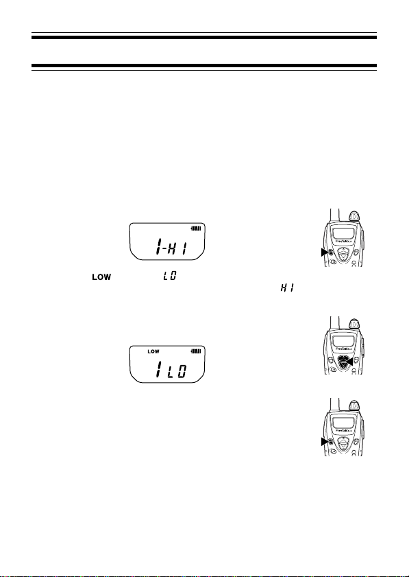
To change the transmission power:
1 Press the MENU key 3 times.
• The icon and “ ” appear on the display
when low power is selected. No icon and “ ”
appear for high power.
2 Press the ▲ or ▼ key to select your desired
output power .
3 Press the MENU key 1 time to confirm the
setting.
22
Page 29

KEY LOCK
You can lock the MENU, ▲, and ▼ keys to prevent
accidentally changing the operating mode and channel
settings. The PTT, CAL, and MON keys still function normally.
Press and hold the MENU key for 1 second to
lock or unlock the transceiver keys.
• The icon appears on the display when the
transceiver keys are locked. No icon appears
when they are unlocked.
LAMP
The lamp is used to illuminate the Liquid Crystal Display . You
can set the lamp to remain off, remain on, or turn on when
you press any key other than the PTT switch (auto). When set
to auto, the lamp remains on for 5 seconds after pressing a
key before turning off again.
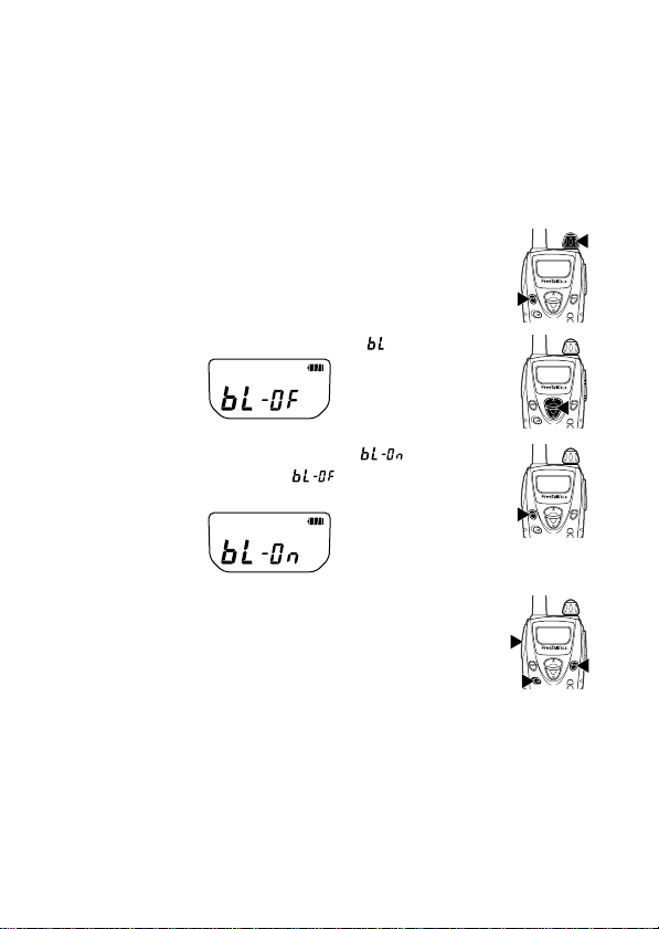
To select the lamp setting:
1 Turn the transceiver power OFF.
2 Press and hold the MENU key while turning
the transceiver power ON (for 1 second).
3 Press the ▲ or ▼ key to select “
”.
23
Page 30

4 Press the MENU key to select “
off), “
5 Press the PTT, MON, or CAL key to exit
Setting Mode.
” (lamp on), or “ ” (lamp auto).
” (lamp
TIME-OUT TIMER
The purpose of the Time-out Timer is to prevent you from
using a channel for a long time. This function is useful, for
example, when you accidentally keep the PTT switch pressed.
Additionally, by limiting the amount of time you can
continuously transmit, this feature helps you save on battery
power consumption.
If you continuously transmit for 3 minutes (default value), the
transceiver will stop transmitting and a tone will sound. To
stop the tone, release the PTT switch. You can press the PTT
switch again to resume transmitting.
This transceiver is also equipped with a pre-alert tone
which sounds 10 seconds before the Time-out Timer expires.
This will allow you time to finish your message before the
transceiver automatically stops transmitting.
To change the default value of 3 minutes:
1 Turn the transceiver power OFF.
2 Press and hold the MENU key while turning
the transceiver power ON (for 1 second).
24
Page 31

3 Press the ▲ or ▼ key to select “
4 Press the MENU key to select “ ”
(3 minutes) or “
5 Press the PTT, MON, or CAL key to exit
Setting Mode.
” (10 minutes).
”.
BATTERY SAVE
This transceiver has been designed to give you the most out
of your battery power . The battery save function decreases
the amount of power used when a signal is not being received
and no operations are being performed.
While using the transceiver, battery save will automatically
switch ON after 10 seconds have elapsed with no operations
or received calls. Operating the transceiver or receiving a call
will switch this feature OFF until 10 seconds of non-operation
occurs again.
You can turn this function ON or OFF:
1 Turn the transceiver power OFF.
2 Press and hold the MENU key while turning
the transceiver power ON (for 1 second).
25
Page 32

3 Press the ▲ or ▼ key to select “
4 Press the MENU key to select “ ” (battery
save on) or “
5 Press the PTT, MON, or CAL key to exit
Setting Mode.
” (battery save off).
”.
BATTERY INDICATOR
When turned ON, the battery indicator on the display lets you
know approximately how much battery life is remaining. When
turned OFF, the battery indicator will appear and blink only
when the battery voltage level is low.
When the battery voltage becomes too low while transmitting,
the transceiver stops transmitting and a tone sounds until you
release the PTT switch. Recharge or replace the battery pack
at this time.
High battery power
Medium battery power
Low battery power
Time to recharge the battery pack
Note: This feature does not measure the accurate battery voltage
when using alkaline batteries. When using alkaline batteries in place
of the supplied battery pack, turn this function OFF.
26
Page 33

You can turn this function ON or OFF:
1 Turn the transceiver power OFF.
2 Press and hold the MENU key while turning
the transceiver power ON (for 1 second).
3 Press the ▲ or ▼ key to select “
4 Press the MENU key to select “ ” (battery
indicator on) to “
5 Press the PTT, MON, or CAL key to exit
Setting Mode.
” (battery indicator off).
”.
CALLING ALERT TONES
Calling alert tones are used to identify yourself to your party
members. You can set up a calling alert tone to one of 6
types. If each party member uses a different calling alert
tone, it is easy to know who is making the call. Pressing the
CAL key before making a call will send your calling alert tone
to your party members.
27
Page 34

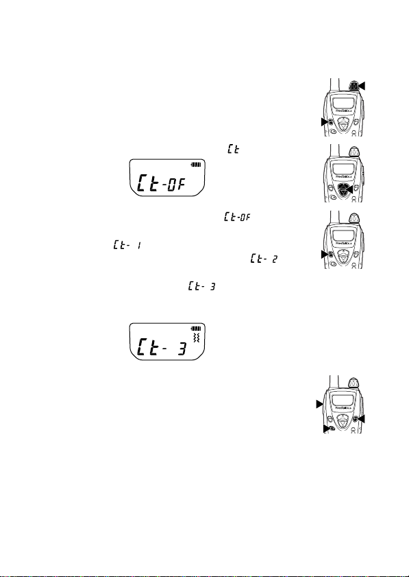
To set up your own calling alert tone:
1 Turn the transceiver power OFF.
2 Press and hold the MENU key while turning
the transceiver power ON (for 1 second).
3 Press the ▲ or ▼ key to select “
”.
4 Press the MENU key to select “ ” (calling
alert tone 1) to “
• Each time you press MENU to select a calling
alert tone, the new tone sounds.
” (calling alert tone 6).
5 Press the PTT, MON, or CAL key to exit
Setting Mode.
INCOMING CALL NOTIFICATION TYPE
Note: To use Incoming Call Notification, you must set up a QT tone
or a DQT code (page 11).
Incoming Call Notification is used to inform you of when a call
is being received. You can set this function to notify you via a
tone or through vibrating. When vibration is activated (either
with the vibration only setting or the vibration and tone
setting), the
icon appears on the display.
28
Page 35

• When set to notify you via a tone only (setting 1), the tone
is emitted when a busy signal is received and the
QT/ DQT signalling matches. The tone will sound for
15 seconds before turning off. While the tone sounds, you
will not hear any audio from the speaker. To turn the tone
off and listen to the received call, press any key. After the
call is finished, the transceiver will wait for 10 seconds
before resetting the Incoming Call Notification. If you
receive a new call within those 10 seconds, the tone will
not sound. If no call is received within 10 seconds,
Incoming Call Notification will reset so that the next time a
call is received, the tone will sound again.
• When set to notify you via vibration only (setting 2), the
transceiver vibrates when a busy signal is received and
the QT/ DQT signalling matches. Audio can be heard from
the speaker while the transceiver vibrates. To stop the
15 second vibrator, press any key. After the call is
finished, the transceiver will wait for 10 seconds before
resetting the Incoming Call Notification.
• When set to notify you via both a tone and through
vibration (setting 3), the tone is emitted and the transceiver
vibrates when a busy signal is received and the QT/ DQT
signalling matches. As with a tone only, you will not hear
audio from the speaker until the tone is stopped by
pressing a key or the 15 second tone stops. After the call
is finished, the transceiver will wait for 10 seconds before
resetting the Incoming Call Notification.
29
Page 36
To select your Incoming Call Notification type:
1 Turn the transceiver power OFF.
2 Press and hold the MENU key while turning
the transceiver power ON (for 1 second).
3 Press the ▲ or ▼ key to select “
4 Press the MENU key to select “ ”
(incoming call notification type off: no tone or
vibration), “
type 1: you are notified by a tone), “
(incoming call notification type 2: you are
notified by vibration), or “
notification type 3: you are notified by both a
tone and by vibration).
5 Press the PTT, MON, or CAL key to exit
Setting Mode.
” (incoming call notification
”.
” (incoming call
”
30
Page 37
BUSY CHANNEL LOCKOUT
This function is used in order to prevent transmitting on a
channel that somebody else is currently using. When turned
ON, a beep sounds when you press the PTT switch while
another party is using the channel, and you cannot transmit.
1 Turn the transceiver power OFF.
2 Press and hold the MENU key while turning
the transceiver power ON (for 1 second).
3 Press the ▲ or ▼ key to select “
4 Press the MENU key to select “ ” (busy
channel lockout on) or “
lockout off).
5 Press the PTT, MON, or CAL key to exit
Setting Mode.
”.
” (busy channel
TRANSCEIVER BEEP
When you turn the transceiver power ON or press a key, a
beep will emit from the transceiver. If desired, you can turn
this feature off:
31
Page 38
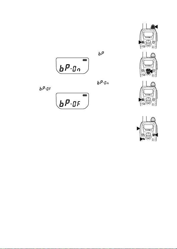
1 Turn the transceiver power OFF.
2 Press and hold the MENU key while turning
the transceiver power ON (for 1 second).
3 Press the ▲ or ▼ key to select “
4 Press the MENU key to select “ ” (beep
on) or “
5 Press the PTT, MON, or CAL key to exit
Setting Mode.
” (beep off).
”.
SIMPLEX/ SEMI-DUPLEX OPERATION
Simplex operation is simply transmitting and receiving between
two parties. This is how you normally operate the transceiver .
However, this transceiver is also capable of using semi-duplex
operation. In semi-duplex operation, you are able to access a
repeater, in order to transmit over longer distances. This can
be useful when a party member is out of range of normal
transmission. In order to use semi-duplex operation, a repeater
must be available in the area. Refer to the channel frequency
tables on pages 41 and 42 for the receive and transmit
frequencies when using simplex or semi-duplex operation.
32
Page 39
Unless you are familiar with the use of repeaters, and are
aware of repeaters near your location, we recommend you do
not use semi-duplex operation; use only simplex operation,
the default frequency bank of this transceiver. There are two
separate “banks” of frequencies stored in the transceiver (as
listed on pages 41 and 42). Frequency Bank A stores those
frequencies used for simplex operation and Frequency Bank B
stores those frequencies used for semi-duplex operation.
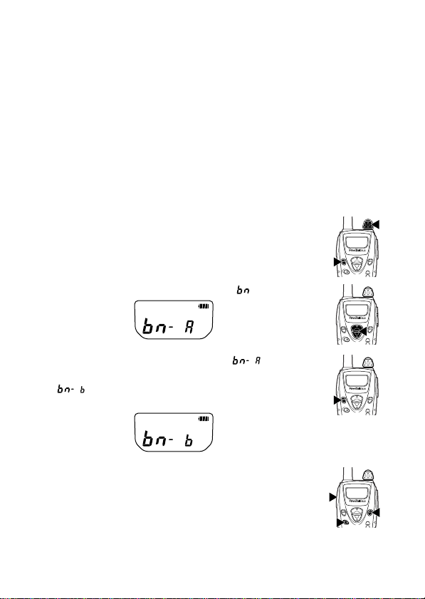
To switch the bank between simplex (A) and semi-duplex (B)
frequencies:
1 Turn the transceiver power OFF.
2 Press and hold the MENU key while turning
the transceiver power ON (for 1 second).
3 Press the ▲ or ▼ key to select “
4 Press the MENU key to select “ ”
(frequency bank A: simplex operation) or
“
” (frequency bank B: semi-duplex
operation).
5 Press the PTT, MON, or CAL key to exit
Setting Mode.
”.
33
Page 40
RESETTING THE TRANSCEIVER
At some point in time, you may desire to reset the transceiver
settings to their default values. The default values of all the
menus can be found on page 43.
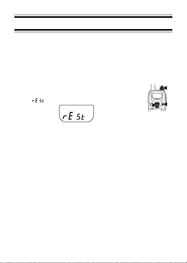
To reset the transceiver:
1 Turn the transceiver power OFF.
2 Press and hold the ▲, ▼, and MON keys
while turning the transceiver power ON.
• (reset) will appear on the display.
3 Release the ▲, ▼, and MON keys to reset
the transceiver settings to their default
values.
34
Page 41
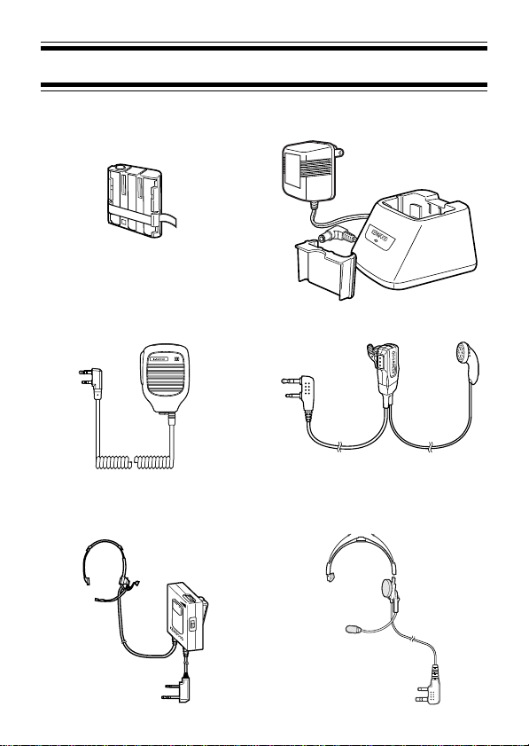
OPTIONAL ACCESSORIES
KNB-27N (Ni-MH battery pack) KSC-28 (Battery charger)
KMC-21 (Speaker-microphone) EMC-3 (Clip mic with earphone)
KHS-1 (Headset) KHS-21 (Headset)
SENS.
PTT
VOX
PTT
35
Page 42

NOTICES TO THE USER
This device complies with Part 15 of the FCC Rules. Operation is
subject to the following two conditions:
(1) this device may not cause harmful interference, and
(2) this device must accept any interference received, including
interference that may cause undesired operation.
One or more of the following statements may be applicable:
FCC W ARNING
This equipment generates or uses radio frequency energy. Changes or
modifications to this equipment may cause harmful interference unless
the modifications are expressly approved in the instruction manual. The
user could lose the authority to operate this equipment if an
unauthorized change or modification is made.
INFORMA TION TO THE DIGITAL DEVICE USER REQUIRED BY THE FCC
This equipment has been tested and found to comply with the limits for a
Class B digital device, pursuant to Part 15 of the FCC Rules. These
limits are designed to provide reasonable protection against harmful
interference in a residential installation.
This equipment generates, uses and can generate radio frequency
energy and, if not installed and used in accordance with the instructions,
may cause harmful interference to radio communications. However,
there is no guarantee that the interference will not occur in a particular
installation. If this equipment does cause harmful interference to radio or
television reception, which can be determined by turning the equipment
off and on, the user is encouraged to try to correct the interference by
one or more of the following measures:
• Reorient or relocate the receiving antenna.
• Increase the separation between the equipment and receiver.
• Connect the equipment to an outlet on a circuit different from that to
which the receiver is connected.
• Consult the dealer for technical assistance.
36
Page 43

SAFETY INFORMATION:
Y our wireless hand-held portable transceiver has been designed using a
low power transmitter.
When the PTT switch is pressed, the transceiver generates radio
frequency (RF) electromagnetic energy (EME).
This transceiver is designed to comply with the FCC Report and Order
FCC 96-326 (August, 1996).
• Do not transmit for more than 50% of the total operating time.
Transmitting for over 50% of the operating time may exceed the
FCC RF exposure compliance requirements. Transmission occurs
while you are pressing the PTT switch and is confirmed by the LED
that lights red while transmitting.
• To transmit, speak into the microphone in your normal voice while
holding the transceiver upright and keep the antenna at least
2 inches (5 cm) from your head and body.
• When using a headset, ensure that the antenna is at least 2 inches
(5 cm) away from your body whenever you are transmitting.
• Use only KENWOOD genuine accessories. Unauthorized
modifications, or attachments may damage the transceiver and
violate FCC rules and regulations.
37
Page 44

QT TONES/ DQT CODES
yalpsiD
rebmuN
FOFFO31zH5.30162zH2.261
10zH0.7641zH2.70172zH9.761
20zH9.1751zH9.01182zH8.371
30zH4.4761zH8.41192zH9.971
40zH0.7771zH8.81103zH2.681
50zH7.9781zH0.32113zH8.291
60zH5.2891zH3.72123zH5.302
70zH4.5802zH8.13133zH7.012
80zH5.8812zH5.63143zH1.812
90zH5.1922zH3.14153zH7.522
01zH8.4932zH2.64163zH6.332
11zH4.7942zH4.15173zH8.142
21zH0.00152zH7.65183zH3.052
klaTteiuQ
ycneuqerF
yalpsiD
rebmuN
klaTteiuQ
ycneuqerF
yalpsiD
rebmuN
klaTteiuQ
ycneuqerF
38
Page 45

yalpsiD
rebmuN
latigiD
klaTteiuQ
edoC
yalpsiD
rebmuN
latigiD
klaTteiuQ
edoC
yalpsiD
rebmuN
10TQD32092TQD47175TQD544
20TQD52003TQD50285TQD464
30TQD62013TQD32295TQD564
40TQD13023TQD62206TQD664
50TQD23033TQD34216TQD305
60TQD34043TQD44226TQD605
70TQD74053TQD54236TQD615
80TQD15063TQD15246TQD235
90TQD45073TQD16256TQD645
01TQD56083TQD36266TQD565
11TQD17093TQD56276TQD606
21TQD27004TQD17286TQD216
31TQD37014TQD60396TQD426
41TQD47024TQD11307TQD726
51TQD41134TQD51317TQD136
61TQD51144TQD13327TQD236
71TQD61154TQD34337TQD456
81TQD52164TQD64347TQD266
91TQD13174TQD15357TQD466
02TQD23184TQD46367TQD307
12TQD43194TQD56377TQD217
22TQD34105TQD17387TQD327
32TQD25115TQD11497TQD137
42TQD55125TQD21408TQD237
52TQD65135TQD31418TQD437
62TQD26145TQD32428TQD347
72TQD56155TQD13438TQD457
82TQD27165TQD234
latigiD
klaTteiuQ
edoC
39
Page 46

SPECIFICATIONS
tuptuOFR
rewoP
snoisnemiD
woLWm005
hgiHW1
rewoPtuptuOoiduAWm001
ytilibatSycneuqerF
egatloVgnitarepOV0.5~V3.3
)dedulcnitonsnoitcejorp(
)N72-BNKhtiw(thgieWzo7/g002
± mpp5.2
mm5.711x57.82x65
)ni8/54x8/11x46/312(
40
Page 47

CHANNEL FREQUENCY CHART:
SIMPLEX OPERATION (FREQUENCY BANK A)
rebmuNlennahC ycneuqerFevieceR ycneuqerFtimsnarT
1zHM5265.264zHM5265.264
2zHM5785.264zHM5785.264
3zHM5216.264zHM5216.264
4zHM5736.264zHM5736.264
5zHM5266.264zHM5266.264
6zHM5786.264zHM5786.264
7zHM5217.264zHM5217.264
)etihW(8zHM0575.264zHM0575.264
)kcalB(9zHM0526.264zHM0526.264
*)egnarO(01zHM0576.264zHM0576.264
11zHM0055.264zHM0055.264
21zHM0006.264zHM0006.264
31zHM0056.264zHM0056.264
41zHM0007.264zHM0007.264
51zHM0527.264zHM0527.264
* Emergency Channel: Use the emergency channel only
for the purpose of soliciting or rendering assistance to a
traveler, or for communicating in an emergency pertaining
to the immediate safety of life or the immediate protection
of property. This channel is used by certain organizations
during emergency situations, and may not necessarily be
monitored.
41
Page 48

CHANNEL FREQUENCY CHART:
SEMI-DUPLEX OPERATION (FREQUENCY BANK B)
rebmuNlennahC ycneuqerFevieceR ycneuqerFtimsnarT
1zHM5265.264zHM5265.264
2zHM5785.264zHM5785.264
3zHM5216.264zHM5216.264
4zHM5736.264zHM5736.264
5zHM5266.264zHM5266.264
6zHM5786.264zHM5786.264
7zHM5217.264zHM5217.264
)etihW(8zHM0575.264zHM0575.764
)kcalB(9zHM0526.264zHM0526.764
*)egnarO(01zHM0576.264zHM0576.764
11zHM0055.264zHM0055.764
21zHM0006.264zHM0006.764
31zHM0056.264zHM0056.764
41zHM0007.264zHM0007.764
51zHM0527.264zHM0527.764
* Emergency Channel: Use the emergency channel only
for the purpose of soliciting or rendering assistance to a
traveler, or for communicating in an emergency pertaining
to the immediate safety of life or the immediate protection
of property. This channel is used by certain organizations
during emergency situations, and may not necessarily be
monitored.
42
Page 49
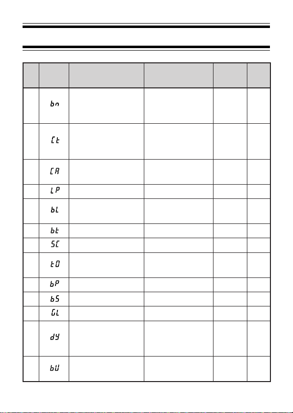
MENUS
yalpsiD
.oN
emaN
1
2
3enoTtrelAgnillaC
4pmaLotuA/NO/FFOotuA32
5
6rotacidnIyrettaBNO/FFONO62
7noitcnuFnacSFFO/NOFFO31
8remiTtuo-emiTsetunim01/3
9peeBFFO/NONO13
01evaSyrettaBFFO/NONO52
11niaGXOV3/2/1/FFOFFO71
21emiTyaleDXOV
31
noitceleS
tuokcoL
ysuBXOV
tuokcoL
emaNlluF sgnitteS
knaBycneuqerF
llaCgnimocnI
epyTnoitacifitoN
lennahCysuB
/)xelpmis(AknaB
-imes(BknaB
)xelpud
/)enoT(1/FFO
/)noitarbiV(2
)noitarbiV+enoT(3
/3/2/1enoT
6/5/4
NO/FFOFFO13
/5.0/3.0/1.0
0.3/5.1/0.1
sdnoces
FFO/NOFFO02
tluafeD
gnitteS
AknaB23
FFO82
1enoT72
3
setunim
5.0
sdnoces
.feR
egaP
42
81
43
Page 50

TROUBLESHOOTING GUIDE
melborP noituloS
ehtnruttonnaC
.NO
retfayltrohs
.gnigrahc
rehtoraeh
.puorg
seciovrehtO
puorgsediseb(
era)’srebmem
ehtnotneserp
.lennahc
tnerappaon
.nosaer
•
rewopreviecsnart
•
seidrewopyrettaB
•.dehsinifsiefilkcapyrettabehT
.eno
rootklattonnaC
•
ruoynisrebmem
•
•
•
•.sgnittesTQD/TQehtegnahC
sireviecsnartehT
•debircsedsareviecsnartehtteseR
rofgninoitcnuflam
.puorgruoy
.43egapno
ebyamkcapyrettabroseirettabehT
roseirettabehtecalpeR.daed
.kcapyrettabehtecalperroegrahcer
ebtonyamkcapyrettabehT
ehtevomeR.yltcerrocdellatsni
.niagatillatsnidnakcapyrettab
wenahtiwkcapyrettabehtecalpeR
emasehtgnisuerauoyerusekaM
sagnittesTQD/TQdnaycneuqerf
.puorgruoynisrebmemrehtoeht
emasehtgnisuerauoyerusekaM
xelpmis:Aknab(knabycneuqerf
xelpud-imes:Bknabronoitarepo
nisrebmemrehtoehtsa)noitarepo
gnisuebyamsrebmempuorgrehtO
ruoynonruT.klaTycavirP
.klaTycavirPs’reviecsnart
ootebyamsrebmempuorgrehtO
nihtiwerauoyerusekaM.yawaraf
.sreviecsnartrehtoehtfoegnar
srebmempuorgllaerusekaM
riehtnosgnittesehtegnahc
wenehthctamotsreviecsnart
.gnittesTQD/TQ
44
Page 51

Page 52

Federal Communications Commission
1270 Fairfield Road
Gettysburg PA 17325-7245
Approved by OMB
3060-0136
Estimated public
burden is 6 minutes
TEMPORARY PERMIT TO OPERATE A
GENERAL MOBILE RADIO SERVICE SYSTEM
Public reporting burden for this collection of information is estimated to average six minutes per response, including the time for revie
instructions, searching existing data sources, gathering and maintaining the data needed, and completing and reviewing the colle
of information. Send comments regarding this burden estimate, or any other aspect of this collection of information, inclu
suggestions for reducing the burden to Federal Communications Commission, AMD-PERM, Washington, DC 20554, Paperwork Reducti
Project (3060-0136), or via the Internet to jboley@fcc.gov.
1
INSTRUCTIONS
l Use this form only if you want a Temporary Permit in the General Mobile Radio Service to share
multiple-licensed or cooperative-shared mobile relay station while your application, FCC Form 574 , is being
processed by the Federal Communications Commission.
l Do not use this form if you operate an individual , non-shared station or if you will be the first user of a facility
intended for shared use.
l Do not use this form for any radio service other than the General Mobile Radio Service.
l Do not use this form unless you are an individual. Partnerships, associations, corporations, and governmental
entites are not eligible for a license in the General Mobile Radio Service.
2
CERTIFICATION
Read, Fill in
Blanks and Sign
l I am not a foreign government or a representative thereof.
l I am eligible in the General Mobile Radio Service under Rule Section 95.5.
l I have not been denied a license or had my license revoked by the FCC.
l I am not the subject of any other legal action concerning the operation of a radio station.
l My completed Form 574 has been mailed to the FCC.
I hereby certify that:
Mailing Address of Applicant (Number, Street, City, State, ZIP Code)
Name of Applicant
Si t fA li t
Date Form 574 Mailed to FCC
Page 53

Signature of Applicant
If you cannot certify to all of the above statements, you are not eligible for a Temporary Permit. Willful fals
statements made on this form are punishable by fine and/or imprisonment (U.S. Code, Title 18, Section 1001)
and/or revocation of any station license or construction permit (U.S. Code, Title 47, Section 312(A)(1)), and/or
forfeiture (U.S. Code 47, Section 503).
3
TECHNICAL
INFORMATION
Location of Control Station(s) or point(s)
Location of Existing Licensed Facility
Number of Mobile Units Licensee Presently Operating on the Shared Facility
Call SignName
4
TEMPORARY
CALL SIGN
l Complete the blocks as indicated.
Use this temporary call sign until a call sign is assigned by the Federal Communications Commission.
Your temporary call sign will consist of the letters “WT” plus your business
residence telephone number.
W
T
l Your authority under this Permit is subject to all applicable treaties, statutes and rules a
is subject to the right of use or control by the Government of the United States.
l This Permit is valid for 180 days from the date the Form 574 is mailed to the FCC.
l You must have a Temporary Permit or a license from the FCC to operate your Genera
Mobile Radio Service system transmitters.
l This Temporary Permit must be kept with your station records until your license is receive
5
LIMITATIONS
DO NOT SUBMIT THIS FORM TO THE FCC
FCC 574T
March 1998
Page 54

 Loading...