

Page 1
INSTRUCTION MANUAL
VHF FM TRANSCEIVER (TK-2100)
ProTalk™ VHF
UHF FM TRANSCEIVER (TK-3100)
ProTalk™ UHF
KENWOOD CORPORATION
©B62-0950-30 (K)
09 08 07 06 05 04 03
Page 2

INTRODUCTION
KENWOOD welcomes you to the Business Radio Service
(BRS). Your KENWOOD 2-way Business Radio is called a
'Iransceiveh’, meaning ‘Iransmitter and receiver”.
For your convenience, this transceiver is equipped with
automatic squelch control which quiets your transceiver
when you are not receiving any calls. For your privacy, this
transceiver provides you with a feature called Quiet Talk
(QT). This feature allows you to use the same channel as
others without having to listen to their conversations.
Another feature of this transceiver is its sliding battery pack
which simplifies installing, removing, and charging.
Your transceiver provides safety and convenience almost
anywhere, indoors or out. It follows both EMI
(Electromagnetic interference) and military standards. The
communications range depends on your location, and can
be up to 5 miles (8 km) in open areas (refer to the chart
below for talk ranges).
This KENWOOD transceiver is a precision device. Treat it
with care, and you will enjoy years of reliable operation.
Conditions
open locations
(no obstructions)
Residential areas
(near buildings)
• In steel/ concrete
reinforced buildings
• In high rises
Note: The listed ranges are based on field testing and may ve^ry with
individual transceivers.
ProTalk™ VHF range
up to 5 miles (8 km)
Up to 2.5 miles (4 km)
• Up to 180,000 sq. ft
(55,000 sq. m)
• Up to 10 floors
ProTalk™ UHF range
Up to 5 miles (8 km)
Up to 2 miles (3 km)
• Up to 250.000 sq. ft
(76,000 sq. m)
• Up to 20 floors
Page 3

FCC LICENSE INFORMATION
Your KENWOOD radio operates on communications
frequencies which are subject to FCC (Federal
Communications Commission) Rules & Regulations.
FCC Rules require that all operators using Private Land
Mobile radio frequencies obtain a radio license before
operating their equipment. Application for license must
be made on FCC form 600, and schedules D, E. and G.
FAX: Forms can be obtained by fax from the FCC Fax-
On-Demand system. Call 1 -202-418-0177 from your fax
machine and request document number 000600 for the
form, schedules, and instructions.
MAIL: Forms can be ordered by telephone, and will be
sent to you by first class mail. Call the FCC Forms
Hotline at 1-800-418-FORM (1-800-418-3676).
INTERNET: Form 600 and instructions can be
downloaded from the FCC Forms website at
http://www.fcc.gov/formpage.html
Before filling out your Form 600 application Technical
Data section, you must decide which frequency (or
frequencies) you will operate on. See the frequency
charts on page 9.
QUESTIONS? Cal! the FCC for license application
questions at 1-888-CALL-FCC (1-888-225-5322).
Page 4

MODELS COVERED BY THIS MANUAL
ProTalk^*^ VHF(TK-2100):
1 channel VHF FM Transceiver/
2 channel VHF FM Transceiver
ProTalk^'^ UHF (TK-3100):
1 channel UHF FM Transceiver/
2 channel UHF FM Transceiver
NOTICES TO THE USER
• GOVERNMENT LAW PROHIBITS THE OPERATION OF
UNLICENSED RADIO TRANSMITTERS WITHIN THE
TERRITORIES UNDER GOVERNMENT CONTROL
• ILLEGAL OPERATION IS PUNISHABLE BY FINE OR
IMPRISONMENT OR BOTH.
SAFETY: It is important that the operator is aware of,
and understands, hazards common to the operation of
any transceiver.
PRECAUTIONS
• Refer service to qualified technicians only.
• Do not operate your transceiver or charge your
battery pack in an explosive atmosphere (gases,
dust, fumes, etc.).
• Turn OFF your transceiver while taking on fuel, or
while parked in gasoline service stations.
• Do not modify this transceiver for any reason.
• Do not expose the transceiver to long periods of
direct sunlight, nor place it close to heating
appliances.
• Do not place the transceiver in excessively dusty,
humid, and wet areas, nor on unstable surfaces.
iv
Page 5

One or more of the following statements may be
applicable:
FCC WARNING
This equipment generates or uses radio frequency energy. Changes
or modifications to this equipment may cause harmful interference
unless the modifications are expressly approved in the instmction
manual. The user could lose the authority to operate this equipment
if an unauthorized change or modification is made.
INFORMATION TO THE DIGITAL DEVICE USER REQUIRED BY
THE FCC
This equipment has been tested and found to comply with the limits
fora Class B digital device, pursuant to Part 15 of the FCC Rules.
These limits are designed to provide reasonable protection against
harmful interference in a residential installation.
This equipment generates, uses and can generate radio freauency
energy and. if not installed and used in accordance with the
instructions, may cause harmful interference to radio communications.
However there is no guarantee that the interference will not occur in a
particular installation. If this equipment does cause harmful
interference to radio or television reception, which can be determined
by turning the equipment off and on. the user is encouraged to try to
correct the interference by one or more of the following measures:
* Reorient or relocate the receiving antenna.
• Increase the separation between the equipment and receiver
• Connect the equipment to an outlet on a circuit different from that
to which the receiver is connected.
* Consult the dealer for technical assistance.
ATTENTION (U.S.A. Only):
The RBRC Recycle seal found on KENWOOD
nickehcadmium (Nl-Cd) battery packs indicates
KENWOODs voluntary participation in an industry
program to collect and recycle Ni-Cd batteries after
their operating life has expired. The RBRC program
is an alternative to disposing Ni-Cd batteries with
your regular refuse or in municipal waste streams,
which is illegal in some areas.
For information on Ni-Cd battery recycling in your area, call (toll free)
1-800-8-BATTERY (1-800-822-8837).
KENWOOD s involvement in this program is part of our commitment
to preserve our environment and conserve our natural resources.
Page 6

CONTENTS
UNPACKING AND CHECKING EQUIPMENT
Supplied Accessories
PREPARATION.........................................................
Installing/ Removing the NiCd Battery Pack
Installing the Antenna
Installing the Belt Clip
Installing the Cover over the Speaker/
Microphone Jacks
Installing the (Optional) Speaker/Microphone
GEHING ACQUAINTED...................................................6
OPERATING BASICS..................................................... 7
CHANNEL FREQUENCY SELECTION
QUIET TALK (QT) ....................................................... 11
QTTone Setup
CHANNEL SEniNG CONFIRMATION.................................16
Frequency Confirmation
QT Tone Confirmation
.......................................................
...........................................
...........................................
...........................................
...................................................
.................................
..........................................
.............................................
.....................
................
.................
5
5
8
12
16
16
Confirmation Beep Patterns...................................... 17
Reference Tables
TRANSCEIVER FUNCTIONS
Time-out Timer (TOT)
Battery Save
Low Battery Warning...............................................18
CHARGING THE NiCd BAnERY PACK
OPTIONAL ACCESSORIES............................................ 21
TROUBLESHOOTING GUIDE
VI
...................................................
..........................................
..............................................
.........................................................
..............................
..........................................
17
18
18
18
19
22
Page 7

UNPACKING AND CHECKING EQUIPMENT
Carefully unpack the transceiver. We recommend that
you identify the items listed in the following table before
discarding the packing material. If any items have been
damaged during shipment, file a claim with the carrier
immediately.
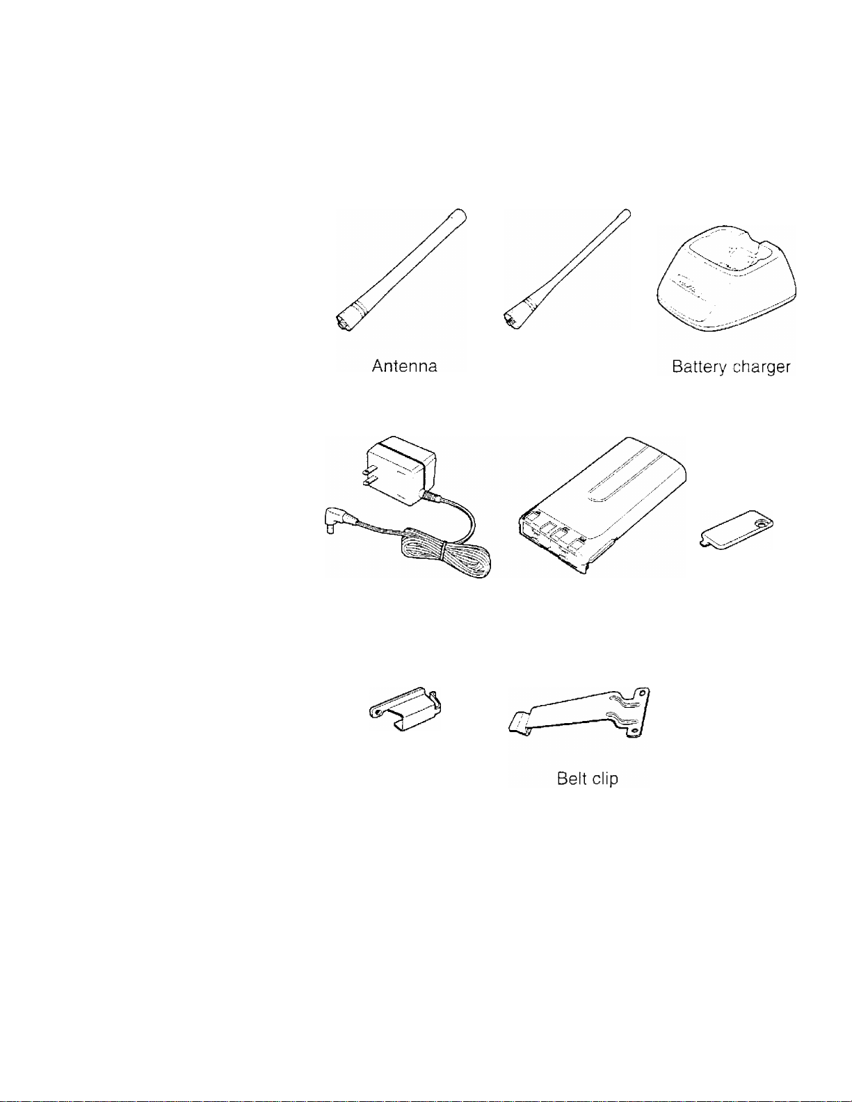
Supplied Accessories
w
Item
Antenna
Battery c
AC adaptor W08-0551-X5
NiCd battery pack
(KNB-14)
Speaker/ microphone
jack cover
Speaker/ microphone
locking bracket
Belt clip
Screw set
Warranty card
instruction manual
ProTalk™ VHP
ProTaik™ UHF
narger W08-0552-X5
Part Number
T90-0695-X5
T90-0694-X5
W09-0939-X5
B09-0351-X3
J21-4493-X4 1
J29-0624-03
N99-0396-X5
B62-0950-XX
Quantity
1
1
1
1
1
1
1
1
1
Page 8
Antenna
(ProTalk™ VHP) (ProTalk’^ UHF)
AC adaptor NiCd battery Speaker/ microphone
pack (KNB-14) jack cover
f‘<33
Speaker/ microphone
locking bracket
Screw set
Page 9
PREPARATION
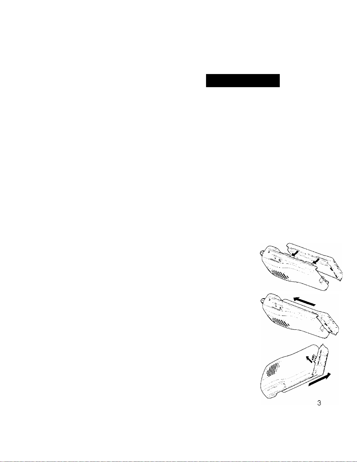
■ Installing/ Removing the NiCd Battery Pack
The battery pack is not charged at the factory;
charge it before use {page 19}.
Average battery pack life:
• KNB-14 (supplied): 8 hours (ProTaik™ VHF/UHF)
• KNB-15A (optional): 10 hours (ProTalk^^ VFIF/ UFIF)
Average times are calculated using 5% transmit
time, 5% receive time, and 90% standby time.
CAUTION:
♦ DO NOT SHORT THE BATTERY TERMINALS OR DISPOSE
OF THE BATTERY BY FiRE.
♦ NEVER ATTEMPT TO REMOVE THE CASING FROM THE
BATTERY PACK.
1 Match the four grooves of
the battery pack with the
corresponding guides on
the back of the
transceiver.
2 Slide the battery pack
along the back of the
transceiver until the
release latch on the base
of the transceiver locks.
3 To remove the battery
pack, puli back on the
release latch and slide
the pack away from the
transceiver.
Page 10

Installing the Antenna
Screw the antenna into the
connector on the top of the
transceiver by holding the
antenna at its base and
turning it clockwise until
secure.
Note: The antenna is neither a
handle, a key ring retainer, nor a
speaker/ microphone attachment
point. Using the antenna in these
ways may damage the antenna and
degrade your transceivers
performance.
Installing the Belt Clip
If necessary, attach the belt
clip using the two supplied
3x8 mm screws.
Note: If the belt clip is not installed,
its mounting location may get hot
during continuous transmission or
when left sitting in a hot environment.
CAUTION: DO NOT USE GLUE
WHICH IS DESIGNED TO PREVENT
SCREW LOOSENING WHEN
INSTALLING THE BELT CLIP. AS IT
MAY CAUSE DAMAGE TO THE
TRANSCEIVER. ACRYLIC ESTER.
WHICH IS CONTAINED IN THESE
GLUES. MAY CRACK THE
TRANSCEIVER’S BACK PANEL
T
Antenna
L
Belt
clip
Page 11

Installing the Cover over the Speaker/ Microphone Jacks
If you are not using a
speaker/ microphone, install
the cover over the speaker/
Speaker/
microphone
jack cover
microphone jacks using the
supplied 3x6 mm screw.
Note: To keep the transceiver water
resistant you must cover the
speaker/ microphone jacks with the
supplied cover.
Installing the (Optional) Speaker/ Microphone
1 Insert the speaker/
microphone plugs into the
speaker/ microphone
jacks.
2 Attach the locking bracket
using the supplied
3x6 mm screw.
Note: The transceiver is not fully
water resistant while using the
speaker/ microphone.
locking bracket
Page 12

GEniNG ACQUAINTED
Speaker/
microphone
jacks
Press this switch, then speak into the microphone to
call a station. Release the switch to receive.
d) Monitor key
Press and hold this key to turn the squelch OFF.
You will hear background noise. Release the key to
turn the squelch back ON.
(D Channel switch (2 channel model only)
Toggle this switch to select channel 1 or channel 2.
© LED indicator
Lights red while transmitting, green while receiving a
signal, and orange while in setup mode. Flashes red
when the battery voltage is low while transmitting.
® Power switch/ Volume control
Turn clockwise to switch ON the transceiver. Turn
counterclockwise until a click sounds, to switch OFF
the transceiver. Rotate to adjust the volume level.
6
Page 13

OPERATING BASICS
1 Switch ON the transceiver by turning
the Power switch/ Volume control
clockwise.
• A beep sounds.
2 Adjust the volume by pressing and
holding the Monitor key, then rotating
the Power switch/ Volume control.
3 Use the Channel switch (2 channel
model only) to choose your desired
channel.
• When you receive an appropriate
signal, you will hear audio from the
speaker.
4 To make a call, press and hold the
PTT switch, then speak into the
microphone using your normal
speaking voice.
• Hold the microphone approximately
1.5 inches (3 to 4 cm) from your lips.
5 Release the PTT switch to receive.
Note:
♦ The channel in use may have been programmed
with a signalling code. Refer to "QUIET TALK
(QTr on page 11.
♦ When the battery pack voltage becomes too low.
transmission will stop and the LED will blink red.
Refer to "Low Battery Warning'' on page 18.
♦ Channels are preprogrammed with frequencies
and QT tones. Refer to "Reference Tables" on
page 17.
Page 14

CHANNEL FREQUENCY SELECTION
You can change the frequency on each channel.
The transceiver will exit the setup mode if no operation
is performed within 5 seconds.
1 Press and hold the PTT switch and
Monitor key, then turn the power ON.
• Continue to hold the PTT switch and
Monitor key until the LED lights
orange, then release the keys.
2 Press the PTT switch.
• The LED changes from orange to red
and a beep sounds. The transceiver
is now in frequency setup mode.
3 Use the Channel switch (2 channel
model only) to choose the channel
you want to set up.
4 Press the PTT switch to change the
frequency number.
• Each time you press the PTT switch, a
beep sounds and the frequency
number changes. There are a total of
4 different frequencies (1 4) for the
ProTalk'^'^ VHP and 8 different
frequencies (1 ~ 8) for the
ProTalk™ UHF.
8
Page 15

ProTalk^M VHP:
Frequency
Action
No.
Press PTT 1 time
Press PTT 2 times
Press PTT 3 times
Press PTT 4 times
Note: Pressing the PTT switch more than 4 times
will cause an error tone to sound, and no value will
be selected.
1
2
3
4
Value (MHz)
151.6250 Red
151.9550
154.5700 Blue
154.6000
Purple
Green
ProTalk^M yHF:
Frequency
Action
No. Value (MHz)
Press PTT 1 time
Press PTT 2 times 2
Press PTT 3 times
Press PTT 4 times 4
Press PTT 5 times 5
Press PTT 6 times 6
Press PTT 7 times 7
Press PTT 8 times 8
1
464.5000
464,5500
3 467.7625
467.8125
467.8500 Silver Star
467.8750
467.9000 Red Star
467.9250
Brown
Yellow
J
K
Gold Star
Color
Color
Blue Star
Beep
pattern
•
• •
• • •
«• •«
Beep
pattern
•
* *
# • #
• • • •
_
%
_
• •
_
• • •
Note:
♦ Pressing the PTT switch more than 8 times will
cause an error tone to sound, and no value will
be selected.
If you are a new licensee, please do not use
frequencies 3 (color: J) and 4 (color: K). If you
have any questions, please call
U888-CALL-FCC (1-888-225-5322).
5 Wait for 2 seconds to hear the beep
pattern of the selected frequency
number.
Page 16

6 Press the Monitor key to complete the
setting.
• The red LED blinks twice.
7 Press the Monitor key again to
confirm the beep pattern of the
selected frequency number.
8 On the 2 channel model, repeat steps
3 to 7 to set up the other channel.
Example of setting a channel to frequency no. 3:
1 After entering frequency setup mode, select
channel 1.
2 Press the PTT switch 3 times to select frequency 3
(ProTalk™ VHP: Blue/ ProTalk™ UHF: J).
• A beep sounds each time you press the PTT switch.
3 Wait for 2 seconds to hear the beep pattern of the
frequency number.
• Three short beeps sound.
4 Press the Monitor key.
• The red LED blinks twice.
5 Press the Monitor key again.
• Three short beeps sound to confirm that frequency 3
has been selected.
10
Page 17

QUIET TALK (QT)
QT allows you to hear only signals on your channel
which are coded to match your transceiver. When a
received signal has a code different from the one set up
in your transceiver, squelch will not open and you will
not hear the signal. When a received signal has a code
that matches your code, squelch will open and you will
hear the signal.
Likewise, when you transmit on a channel set up with
QT, the receiving station must have a matching code in
order to hear your signal.
• QT tones are selected from 38 standard signalling codes
(see the table below).
• Selecting "OO’* will turn signalling OFF.
Code
xz
XA
WA 03 74.4 2A 16
XB
WB 05 79.7
YZ
YA 07 85.4
YB
ZZ
ZA 10 ^ 94.8
ZB 11
1Z
1A 13 103.5 5B
No.
01
02
04
06 82.5 3A
08 88.5 4Z 21 136.5
09 91.5 4A
12
(Hz)
67.0
71.9 2Z 15 110.9
77.0 2B 17 118.8
97.4
100.0
Code No.
1B
3Z 18 123.0
3B 20 131.8
4B
5Z
5A
14 107.2
19
22
23 146.2
24 151.4
25
26
Freq.
Freq.
(Hz)
114.8
127.3
141.3
156.7
162.2
Code
No.
(Hz)
27
Freq.
6Z
6A 28 173.8
6B
7Z 30 186.2
7A 31 192.8
Ml 32 203.5
M2
M3
M4
M5 36 233.6
M6
M7 38 250.3
—
167.9
29 179.9
210.7
33
34
218.1
225.7
35
37 241.8
00
OFF
11
Page 18

QT Tone Setup
Note:
♦ Refer to the signalling codes listed in the table on page 11.
♦ When selecting a single digit number (0 ~ 9). always use 2 digits
(00 ~ 09).
♦ When you are confirming the selected signalling number, there
Is a short pause between the 10s digit and the 1'$ digit.
The transceiver will exit the setup mode if no
operation is performed within 5 seconds.
1 Press and hold the PTT switch and^^^i
Monitor key, then turn the power
ON.
• Continue to hold the PTT switch
and Monitor key until the LED
lights orange, then release the
keys.
Press the Monitor key.
■¿j’
• The LED changes from orange to
green and a beep sounds. The
transceiver is now in QT tone setup
mode.
Use the Channel switch (2
channel model only) to choose the
channel you want to set up.
12
Page 19

4 Press the PTT switch to select the
10’s digit of the signalling number
• Each time you press the PTT
switch, a beep sounds and the 10's
digit of the signalling number
changes. There are a total of 4
different numbers (0 3).
Action
Press and hold PTT for 2 seconds
Press PTT 1 time ! 1 x
Press PTT 2 times | 2 x
Press PTT 3 times
Note:
♦
To select V". press and hold the PTT switch
until a 1 second tone sounds (approximately
2 seconds).
Pressing the PTT switch more than 3 times
will cause an error tone to sound, and no
value will be selected.
Vaiua
Ox 1 second tone
1
3 X • * *
5 Wait for 2 seconds to hear the
beep pattern of the 10’s digit
number you selected .
6 Press the PTT switch to select the
1’s digit of the signalling number
Beep pattern
•
■ •
* Each time you press the PTT
switch, a beep sounds and the 1's
digit of the signalling number
changes. There are a total of 10
different numbers (0 ~ 9).
13
Page 20

---------------------------------------------------------------^
Action I Value
---------------
Beep pattern
Press and hold PTT for 2 seconds j x 0
--------------------------------------------------------------
Press PTT 1 time x 1
Press PTT 2 times ! x 2
Press PTT 3 times x 3
Press PTT 4 times
Press PTT 5 times
Press PTT 6 times
Press PTT 7 times 1 x 7
Press PTT 8 times | x 8
Press PTT 9 times x 9
Note:
♦
To select V’: press and hold the PTT switch
until a 1 second tone sounds (approximately
2 seconds).
Pressing the PTT switch more than 9 times
will cause an error tone to sound, and no
value will be selected. (If you set the 10s
digit to an error will occur after pressing
the PTT switch more than 8 times.)
n
1
X 4
X 5
X 6
1 second tone
•
• •
• • •
« ft • •
_
ft
— ft ft
— ft ft ft
^ ft ft ft ft
1 Wait for 2 seconds to hear the
beep pattern of the Vs digit
number you selected.
8 Press the Monitor key to complete
the setting.
• The green LED blinks twice.
14
Page 21

9 Press the Monitor key again to
confirm the beep pattern of the
selected signalling number.
10 On the 2 channel modeL repeat
steps 3 to 9 to set up the other
channel.
Example of setting up a channel with QT tone no. 01:
1 After entering QT setup mode, select channel 1.
2 Press and hold the PTT switch until a 1 second tone
sounds, to select 0 for the 10’s digit (approximately
2 seconds).
3 Wait for 2 seconds.
• A 1 second tone will sound to confirm that 0 has been
selected.
4 Press the PTT switch 1 time to select 1 tor the Ts
digit,
• A beep sounds when you press the PTT switch.
5 Wait for 2 seconds.
• A short beep will sound to confirm that 1 has been
selected.
6 Press the Monitor key.
• The green LED blinks twice.
7 Press the Monitor key again.
• A 1 second tone will sound (0), there will be a short
pause, and then a short beep will sound (1) to confirm
that 01 has been selected.
15
Page 22

CHANNEL SETTING CONFIRMATION
You can confirm the channel settings of your transceiver
Note: Añer confirming a setting, you must turn the power OFF and then
ON again so the transceiver can operate normally.
■ Frequency Confirmation
1 Select the channel you want to confirm.
2 Press and hold the PTT switch, then turn the
power ON.
• The beep pattern will sound, [i.e.- if freqency 3
(ProTalK™ VHF: Blue./ ProTalk™ UHF: J) is set up
on the channel 3 short beeps will sound.]
Turn the power OFF after confirming the number3
4
On the 2 channel model, repeat steps 1 to 3 to
confirm the frequency of the other channel
QT Tone Confirmation
Note: There is a short pause between the confirmation of the 10's
digit and the confirmation of the 1 s digit.
1 Select the channel you want to confirm.
2 Press and hold the Monitor key, then turn the
power ON.
• The beep pattern will sound, [i.e.- If QT tone 01 is
set up on the channel a 1 second tone will sound
(0), there will be a short pause, and then a short
beep will sound (1).]
3 Turn the power OFF after confirming the number
4 On the 2 channel model, repeat steps 1 to 3 to
confirm the QT tone of the other channel
16
Page 23

Confirmation Beep Patterns
Number
0
1
2
3
4
Beep pattern
1 second tone
•
• •
• • •
•«• •
Number Beep pattern
5
6
7
8 ; -•••
9
Reference Tables
Factory Default Channel Settings:
Channel
1
2
Personal Channel Settings:
Blue {154.5700 MHz)/
Quiet Talk; 01 {67,0 Hz)
Green (154.6000 MHz)/
Quiet Talk: 01 (67.0 Hz)
ProTalk™ VHF
Yellow (464.5500 MHz)/
Quiet Talk: 01 (67.0 Hz)
Blue Star (467.9250 MHz)/
Quiet Talk: 01 (67.0 Hz)
• • • • •
— •
— • •
~ •
ProTalk™ UHF
Channel
number
1
2
Frequency setting
Signalling setting
17
Page 24

TRANSCEIVER FUNCTIONS
Time-out Timer (TOT)
The purpose of the Time-out Timer is to prevent any
single person from using a channel for an extended
period of time.
If you continuously transmit for 3 minutes, the
transceiver will stop transmitting and a tone will
sound. To stop the tone, release the PTT switch.
You can press the PTT switch again to resume
transmitting.
Battery Save
The Battery Save function decreases the amount of
power used when a signal is not being received and
no operations are being performed (no keys are
being pressed, and no switches are being turned).
While the channel is not busy and no operation is
performed for 10 seconds, Battery Save is enabled.
When a signal is received or an operation is
performed, Battery Save is disabled.
Low Battery Warning
Low Battery Warning alerts you when the battery
needs to be recharged.
While transmitting, if the battery power goes below a
pre-determined value, the LED will blink red. When
a tone sounds, the transceiver stops transmitting.
Replace or recharge the battery pack.
18
Page 25

CHARGING THE NiCd BAHERY PACK
Initially charging the battery pack after purchase or
extended storage (greater than 2 months) will not bring
the battery pack to its normal operating capacity. After
repeating the charge/discharge cycle two or three times,
the operating capacity will increase to normal.
CAUTION:
♦ DO NOT RECHARGE THE BATTERY PACK IF IT IS ALREADY
FULLY CHARGED. DOING SO MAY CA USE THE LIFE OF THE
BATTERY PACK TO SHORTEN OR THE BATTERY PACK MAYBE
DAMAGED.
♦ AFTER RECHARGING THE BATTERY PACK. DISCONNECT IT
FROM THE CHARGER. CHARGING THE BATTERY PACK FOR
MORE THAN 5 DAYS MAY REDUCE THE BATTERY PACK LIFE
DUE TO OVERCHARGING.
Note:
♦ The ambient temperature should be between 41 and 104~F
(5 and 40^C) while charging is in progress. Charging outside this
range may not fully charge the battery.
♦ Always switch OFF the transceiver equipped with a NiCd battery
pack before charging. Using the transceiver while charging its
battery pack will interfere with correct charging.
♦ The battery pack life is over when its operating time decreases
even though it is fully and correctly charged. Replace the battery'
pack.
19
Page 26

1 Plug the AC adaptor
cable into the adaptor
jack located on the rear
of the charger.
2 Plug the AC adaptor into
an AC outlet.
3 Slide the NiCd battery
pack or the transceiver
equipped with a NiCd
battery pack into the
charging slot.
• Make sure the metal
contacts on the battery
pack come in contact
with the charging
terminals.
• The charger LED lights
and charging begins.
4 After charging the
supplied KNB'14 battery
pack for 8 hours, remove
it or the transceiver from
the charger.
• The charger does not
turn OFF automatically
after charging is
completed.
5 Unplug the AC adaptor
from the AC outlet.
Note: It takes approximately 15 hours to fully charge the optional
KNB-15A battery pack.
20
Page 27

OPTIONAL ACCESSORIES
You can use the following accessories with your
transceiver;
• KNB-14; Standard Battery (7.2 V/ 600 mAh)
• KNB-15A: Long Life Battery (7.2 V/1100 mAh)
• KSC-15: Regular Battery Charger
• KSC-16; Rapid Battery Charger
• KSC-21R: Refreshable Rapid Battery Charger
• KHS-1: Head Set with VOX (Voice Operated
Transmit)
• KMC-17:
• KMC-21;
• KBP-1;
KBH-8: Spring-action Belt Clip
KWR-1: Water Resistant Bag
Speaker/ Microphone (Standard Duty)
Speaker/ Microphone (Light Duty)
Alkaline Battery Case
21
Page 28

No power.
TROUBLESHOOTING GUIDE
Problem I Solution
: • The battery pack may be
dead. Recharge or replace
the battery pack.
• The battery pack may not
be installed correctly.
Remove the battery pack
and install it again.
Battery power dies
shortly after charging.
Cannot talk to or hear
other members in your
group.
Other voices (besides
group members) are
present on the
channel.
The battery pack life is
finished. Replace the battery
pack with a new one.
• Make sure you are using
the same frequency and
Quiet Talk tone as the other
members in your group.
• Other group members may
be too far away. Make sure
you are within range of the
other transceivers.
Change the Quiet Talk tone.
Be sure to change the tone
on all transceivers in your
group.
22
 Loading...