


NX-700 Series/
NX-800 Series
VHF Digital traNSceiVer/ UHF Digital traNSceiVer
iNStrUctioN MaNUal
ÉMetteUr-rÉcePteUr NUMÉriQUe VHF/
ÉMetteUr-rÉcePteUr NUMÉriQUe UHF
MoDe D’eMPloi
traNScePtor Digital VHF/ traNScePtor Digital UHF
MaNUal De iNStrUccioNeS
© B62-2000-00 (K,K2)
09 08 07 06 05 04 03 02 01 00

VHF Digital traNSceiVer/ UHF Digital traNSceiVer
NX-700 Series/ NX-800 Series
iNStrUctioN MaNUal
eNgliSH

Thank You
We are grateful you have chosen Kenwood for your personal mob le appl cat ons. We bel eve th s easy-to-use transce ver w ll prov de dependable commun cat ons to keep personnel operat ng at peak eff c ency.
Kenwood transce vers ncorporate the latest n advanced technology. As a result, we feel strongly that you w ll be pleased w th the qual ty and features of th s product.
nXDn™
NXDN™ s a protocol name for the new d g tal commun cat on system us ng 4-level FSK technology wh ch has been co-developed by Kenwood and Icom.
MoDels CovereD bY This Manual
The models l sted below are covered by th s manual:
•NX-700/ NX-700H: VHF D g tal Transce ver
•NX-800/ NX-800H: UHF D g tal Transce ver
noTiCes To The user
Government law proh b ts the operat on of unl censed transm tters w th n the terr tor es under government control.
Illegal operat on s pun shable by f ne and/or mpr sonment.
Refer serv ce to qual f ed techn c ans only.
SAFETY: It s mportant that the operator s aware of, and understands, hazards common to the operat on of any transce ver.
EXPLOSIVE ATMOSPHERES (GASES, DUST, FUMES, etc.)
Turn OFF your transce ver wh le tak ng on fuel or wh le parked n gasol ne serv ce stat ons. Do not carry spare fuel conta ners n the trunk of your veh cle f your transce ver s mounted n the trunk area.
INJURY FROM RADIO FREQUENCY TRANSMISSIONS
Do not operate your transce ver when somebody s e ther stand ng near to or touch ng the antenna, to avo d the poss b l ty of rad o frequency burns or related phys cal njury.
DYNAMITE BLASTING CAPS
Operat ng the transce ver w th n 500 feet (150 m) of dynam te blast ng caps may cause them to explode. Turn OFF your transce ver when n an area where blast ng s n progress, or where
“TURN OFF TWO-WAY RADIO” s gns have been posted. If you are transport ng blast ng caps
n your veh cle, make sure they are carr ed n a closed metal box w th a padded nter or. Do not transm t wh le the caps are be ng placed nto or removed from the conta ner.
The AMBE+2™ vo ce cod ng Technology embod ed n th s product s protected by ntellectual property r ghts nclud ng patent r ghts, copyr ghts and trade secrets of D g tal Vo ce Systems, Inc. Th s vo ce cod ng Technology s l censed solely for use w th n th s Commun cat ons Equ pment. The user of th s Technology s expl c tly proh b ted from attempt ng to extract, remove, decomp le, reverse eng neer, or d sassemble the Object Code, or n any other way convert
the Object Code nto a human-readable form. U.S. Patent Nos. #5,870,405, #5,826,222, #5,754,974, #5,701,390, #5,715,365, #5,649,050, #5,630,011, #5,581,656, #5,517,511, #5,491,772, #5,247,579, #5,226,084 and #5,195,166.

One or more of the following statements may be applicable:
FCC WARNING
Th s equ pment generates or uses rad o frequency energy. Changes or mod f cat ons to th s equ pment may cause harmful nterference unless the mod f cat ons are expressly approved n the
nstruct on manual. The user could lose the author ty to operate th s equ pment f an unauthor zed change or mod f cat on s made.
INFORMATION TO THE DIGITAL DEVICE USER REQUIRED BY THE FCC
Th s equ pment has been tested and found to comply w th the l m ts for a Class B d g tal dev ce, pursuant to Part 15 of the FCC Rules. These l m ts are des gned to prov de reasonable protect on aga nst harmful nterference n a res dent al nstallat on.
Th s equ pment generates, uses and can generate rad o frequency energy and, f not nstalled and used n accordance w th the nstruct ons, may cause harmful nterference to rad o commun cat ons. However, there s no guarantee that the nterference w ll not occur n a part cular nstallat on. If th s equ pment does cause harmful nterference to rad o or telev s on recept on, wh ch can be determ ned by turn ng the equ pment off and on, the user s encouraged to try to correct thenterference by one or more of the follow ng measures:
•Reor ent or relocate the rece v ng antenna.
•Increase the separat on between the equ pment and rece ver.
•Connect the equ pment to an outlet on a c rcu t d fferent from that to wh ch the rece ver s connected.
•Consult the dealer for techn cal ass stance.
PreCauTions
Observe the follow ng precaut ons to prevent f re, personal njury, and transce ver damage.
•Do not attempt to conf gure the transce ver wh le dr v ng; t s too dangerous.
•Do not d sassemble or mod fy the transce ver for any reason.
•Do not expose the transce ver to long per ods of d rect sunl ght, nor place t near heat ng appl ances.
•If an abnormal odor or smoke s detected com ng from the transce ver, sw tch the transce ver power off mmed ately, and contact your Kenwood dealer.
•Use of the transce ver wh le you are dr v ng may be aga nst traff c laws. Please check and observe the veh cle regulat ons n your area.
•Do not use opt ons not spec f ed by Kenwood.
The transce ver operates n 12 V negat ve ground systems only! Check the battery polar ty and voltage of the veh cle before nstall ng the transce ver.
Use only a Kenwood opt onal DC power cable.
Do not cut and/or remove the fuse holder on the DC power cable.
For passenger safety, nstall the transce ver securely us ng an opt onal mount ng bracket and screw set so the transce ver w ll not break loose n the event of a coll s on.

CONTENTS |
|
UNPACKING AND CHECKING EQUIPMENT .................................... |
1 |
Supplied AcceSSorieS ....................................................................... |
1 |
PREPARATION ................................................................................... |
2 |
ToolS required ................................................................................ |
2 |
power cAble connecTion ................................................................. |
2 |
inSTAlling The TrAnSceiver ............................................................... |
3 |
GETTING ACQUAINTED..................................................................... |
4 |
FronT pAnel..................................................................................... |
4 |
diSplAy............................................................................................. |
5 |
reAr pAnel ...................................................................................... |
6 |
PROGRAMMABLE FUNCTIONS........................................................ |
7 |
BASIC OPERATIONS.......................................................................... |
9 |
SwiTching power on/oFF ............................................................... |
9 |
AdjuSTing The volume....................................................................... |
9 |
SelecTing A Zone And chAnnel/group id.......................................... |
9 |
TrAnSmiTTing................................................................................... |
10 |
receiving........................................................................................ |
11 |
MENU MODE ..................................................................................... |
12 |
menu AcceSS.................................................................................. |
12 |
menu conFigurATion ....................................................................... |
12 |
chArAcTer enTry ........................................................................... |
14 |
SCAN ................................................................................................. |
15 |
TemporAry chAnnel lockouT.......................................................... |
15 |
prioriTy ScAn ................................................................................. |
15 |
ScAn reverT................................................................................... |
16 |
ScAn deleTe/Add............................................................................ |
16 |
prioriTy-chAnnel SelecT ................................................................ |
16 |
FleetSync: ALPHANUMERIC 2-WAY PAGING FUNCTION............ |
17 |
SelcAll (SelecTive cAlling) ........................................................... |
17 |
STATuS meSSAge ............................................................................. |
18 |
ShorT meSSAgeS............................................................................. |
19 |
long meSSAgeS .............................................................................. |
19 |

gpS reporT................................................................................... |
19 |
DTMF (DUAL TONE MULTI FREQUENCY) CALLS........................ |
20 |
mAking A dTmF cAll ..................................................................... |
20 |
AuTodiAl......................................................................................... |
20 |
STun code...................................................................................... |
20 |
TRUNKING CALLS (ANALOG)......................................................... |
21 |
mAking A Telephone cAll ............................................................... |
21 |
receiving A Telephone cAll ........................................................... |
21 |
EMERGENCY CALLS ....................................................................... |
22 |
SCRAMBLER..................................................................................... |
23 |
Secure (encrypTed) TrAnSmiSSion................................................... |
23 |
SIGNALING........................................................................................ |
24 |
quieT TAlk (qT)/ digiTAl quieT TAlk (dqT) ................................... |
24 |
rAdio AcceSS number (rAn) ......................................................... |
25 |
opTionAl SignAling ......................................................................... |
25 |
ADVANCED OPERATIONS .............................................................. |
26 |
clock............................................................................................. |
26 |
lcd brighTneSS............................................................................. |
26 |
horn AlerT .................................................................................... |
26 |
public AddreSS (pA)...................................................................... |
27 |
BACKGROUND OPERATIONS ........................................................ |
28 |
Time-ouT Timer (ToT) ..................................................................... |
28 |
SignAl STrengTh indicATor ............................................................. |
28 |
compAnder ..................................................................................... |
28 |
buSy chAnnel lockouT (bcl)........................................................ |
29 |
conTrol chAnnel hunT .................................................................. |
29 |
pTT id ........................................................................................... |
29 |
VGS-1 OPTIONAL VOICE GUIDE & STORAGE UNIT..................... |
30 |
voice recorder.............................................................................. |
30 |
voice guide .................................................................................... |
31 |
v
UNPACKING AND CHECKING EQUIPMENT
Note: The following unpacking instructions are for use by your Kenwood dealer, an authorized Kenwood service facility, or the factory.
Carefully unpack the transceiver. We recommend that you identify the items listed in the following table before discarding the packing material. If any items are missing or have been damaged during shipment, file a claim with the carrier immediately.
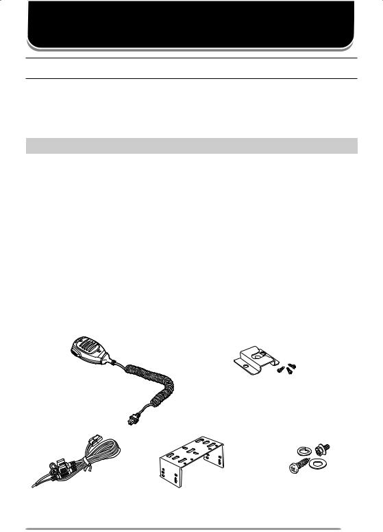
Supplied AcceSSorieS
Item |
Part Number |
Quantity |
|
|
|
|
|
Microphone (with cable) |
T9 -0639-XX |
|
|
|
|
|
|
Microphone hanger |
J 9- 584-XX |
set |
|
(with 4 x 6 mm self-tapping screws) |
|||
|
|
||
DC power cable |
E30-7523-XX |
|
|
|
|
|
|
• Fuse ( 5 A) |
F52-0024-XX |
2 |
|
|
|
|
|
Mounting bracket |
J29-0726-XX |
|
|
|
|
|
|
Screw set: |
|
|
|
• 5 x 6 mm self-tapping screw (4 pieces) |
|
|
|
• Hex-headed screw with washer (4 pieces) |
N99-2068-XX |
|
|
• Spring washer (4 pieces) |
|
|
|
• Flat washer (4 pieces) |
|
|
|
|
|
|
|
Instruction manual |
B62-2000-XX |
|
|
|
|
|
Microphone |
Microphone hanger |
(with cable) |
(with 4 x 6 mm self-tapping screws) |
DC power cable |
Mounting bracket |
Screw set |

PREPARATION
Various electronic equipment in your vehicle may malfunction if they are not properly protected from the radio frequency energy which is present while transmitting. Electronic fuel injection, antiskid braking, and cruise control systems are typical examples of equipment that may malfunction.
If your vehicle contains such equipment, consult the dealer for the make of vehicle and enlist his/her aid in determining if they will perform normally while transmitting.
Note: The following preparation instructions are for use by your Kenwood dealer, an authorized Kenwood service facility, or the factory.
ToolS required
Note: Before installing the transceiver, always check how far the mounting screws will extend below the mounting surface. When drilling mounting holes, be careful not to damage vehicle wiring or parts.
The following tools are required for installing the transceiver:
•/4 inch (6 mm) or larger electric drill
•5/32 inch (4.2 mm) drill bit for the self-tapping screws used to mount the optional mounting bracket
•Circle cutters
power cAble connecTion
The transceiver operates in 12 V negative ground systems only! Check the battery polarity and voltage of the vehicle before installing the transceiver.
Use only a Kenwood optional DC power cable.
Do not cut and/or remove the fuse holder on the DC power cable.
1Check for an existing hole, conveniently located in the firewall, where a power cable can be passed through. If no hole exists, use a circle cutter to drill the firewall, then install a rubber grommet.
2Run the two power cable leads through the firewall and into the engine compartment, from the passenger compartment.
3Connect the red lead to the positive (+) battery terminal and the black lead to the negative (–) battery terminal.
•Locate the fuse as close to the battery as possible.
4Coil and secure the surplus cable with a retaining band.
•Be sure to leave enough slack in the cables so the transceiver can be removed for servicing while keeping the power applied.
2

inSTAlling The TrAnSceiver
For passenger safety, install the transceiver securely using an optional mounting bracket and screw set so the transceiver will not break loose in the event of a collision.
1Mark the position of the holes in the dash by using the mounting bracket as a template. Drill the holes, then attach the mounting bracket using self-tapping screws.
•Be sure to mount the transceiver in a location where the controls are within easy reach of the user and where there is sufficient space at the rear of the transceiver for cable connections.
2Connect the antenna and power cable to the transceiver.
3Slide the transceiver into the mounting bracket and secure it using hex-headed screws.
4Mount a microphone hanger in a location where it will be within easy reach of the user.
•The microphone and microphone cable should be mounted in a location where it will not interfere with the safe operation of the vehicle.
When replacing the fuse in the DC power cable, be sure to replace it with a fuse of the same value. Never replace a fuse with a fuse that has a higher value.
|
|
Flat washer |
|
|
|
Hex-headed |
|
|
Microphone |
|
screws |
Spring washer |
|
|
|
|
|
||
|
|
Self-tapping screw |
|
|
Antenna |
|
|
|
|
connector |
|
|
|
|
Power input |
|
|
|
Mounting |
|
|
|
bracket |
|
connector |
|
|
|
|
|
|
|
|
|
DC power |
|
Ignition |
|
|
cable |
|
|
|
|
sense cable |
|
|
||
|
|
|
||
|
Black (–) cable |
|
2 V vehicle |
|
|
|
Red (+) cable |
Fuse |
battery |
|
|
|
|
|
3
|
GETTING ACQUAINTED |
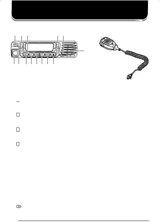
FronT pAnel |
|
q w e |
r t |
|
!5 |
|
!4 |
yu i o !0 1! 2! !3
q (power) switch
Press and hold for approximately second to switch the transceiver power ON and OFF.
w  key
key
Press to activate its programmable function {page 7}. The default setting is Volume Up.
e key
key
Press to activate its programmable function {page 7}. The default setting is Volume Down.
r key
key
Press to activate its programmable function {page 7}. The default setting is Channel/Group ID Up.
t  key
key
Press to activate its programmable function {page 7}. The default setting is Channel/Group ID Down.
yMicrophone jack
Insert the microphone plug into this jack.
uLED indicator
Lights red while transmitting. Lights green while receiving a call.
i  key
key
Press to activate its programmable function {page 7}. The default setting is None (no function).
o  key
key
Press to activate its programmable function {page 7}. The default setting is Menu mode.
!0 key
Press to activate its programmable function {page 7}. The default setting is Squelch Off Momentary.
4
!1 key
Press to activate its programmable function {page 7}. The default setting is Zone Down.
!2 key
key
Press to activate its programmable function {page 7}. The default setting is Zone Up.
!3 key
key
Press to activate its programmable function {page 7}. The default setting is None (no function).
!4Speaker
Internal speaker
!5PTT (Push-to-Talk) switch
Press and hold this switch then, speak into the microphone to call a station.
diSplAy
|
|
|
|
|
|
|
|
|
|
|
|
|
|
|
|
|
|
|
|
|
|
|
|
|
|
|
|
|
|
|
|
|
|
|
|
|
|
|
|
|
|
|
|
|
|
|
|
|
|
|
|
|
|
|
|
|
|
|
|
|
|
|
|
|
|
|
|
|
|
|
|
|
|
|
|
|
|
|
|
|
|
|
|
|
|
|
|
|
|
|
|
|
|
|
|
|
|
|
|
|
|
|
|
|
|
|
|
|
|
Indicator |
|
|
|
|
|
|
|
|
Description |
|||||||||||||||||||||||||||||||||||||||||||||
|
|
|
|
|
|
|
|
|
|
|
||||||||||||||||||||||||||||||||||||||||||||
|
|
|
|
Appears when the Monitor or Squelch Off function is |
||||||||||||||||||||||||||||||||||||||||||||||||||
|
|
|
||||||||||||||||||||||||||||||||||||||||||||||||||||
|
|
|
|
activated. |
|
|
|
|
|
|
|
|
|
|
|
|
|
|
|
|
|
|
|
|
|
|
|
|
|
|
|
|
|
|
|
|
|
|||||||||||||||||
|
|
|
|
|
|
|
|
|
|
|
|
|
|
|
|
|
|
|
|
|
|
|
|
|
|
|
|
|
|
|
|
|
|
|
|
|||||||||||||||||||
|
|
|
|
|
|
|
|
|
|
|
||||||||||||||||||||||||||||||||||||||||||||
|
|
|
|
Blinks when signaling of an incoming call matches the |
||||||||||||||||||||||||||||||||||||||||||||||||||
|
|
|
|
Optional Signaling set up on your transceiver. |
||||||||||||||||||||||||||||||||||||||||||||||||||
|
|
|
|
|
|
|
|
|
|
|
||||||||||||||||||||||||||||||||||||||||||||
|
|
|
|
Appears when the current zone (left icon) or CH/GID (right |
||||||||||||||||||||||||||||||||||||||||||||||||||
|
|
|
|
icon) is added to the scanning sequence. |
||||||||||||||||||||||||||||||||||||||||||||||||||
|
|
|
|
|
|
|
|
|
|
|
||||||||||||||||||||||||||||||||||||||||||||
|
|
|
|
Appears when you are using Scan mode. Blinks while |
||||||||||||||||||||||||||||||||||||||||||||||||||
|
|
|
|
|||||||||||||||||||||||||||||||||||||||||||||||||||
|
|
|
|
paused at a channel. |
||||||||||||||||||||||||||||||||||||||||||||||||||
|
|
|
|
|||||||||||||||||||||||||||||||||||||||||||||||||||
|
|
|
|
|
|
|
|
|
|
|
||||||||||||||||||||||||||||||||||||||||||||
|
|
|
|
Appears when there is a message stored in the transceiver |
||||||||||||||||||||||||||||||||||||||||||||||||||
|
|
|
|
|||||||||||||||||||||||||||||||||||||||||||||||||||
|
|
|
|
memory. Blinks when a new message has arrived. |
||||||||||||||||||||||||||||||||||||||||||||||||||
|
|
|
|
|||||||||||||||||||||||||||||||||||||||||||||||||||
|
|
|
|
|
|
|
|
|
|
|
||||||||||||||||||||||||||||||||||||||||||||
|
|
|
|
Appears when the current channel is programmed as a |
||||||||||||||||||||||||||||||||||||||||||||||||||
|
|
|
|
Priority channel. “ |
|
|
” represents Priority channel . “ |
|
” |
|||||||||||||||||||||||||||||||||||||||||||||
|
|
|
|
|
|
|||||||||||||||||||||||||||||||||||||||||||||||||
|
|
|
|
|||||||||||||||||||||||||||||||||||||||||||||||||||
|
|
|
|
represents Priority channel 2. “ |
|
” represents Priority |
||||||||||||||||||||||||||||||||||||||||||||||||
|
|
|
|
|
||||||||||||||||||||||||||||||||||||||||||||||||||
|
|
|
|
|||||||||||||||||||||||||||||||||||||||||||||||||||
|
|
|
|
|
||||||||||||||||||||||||||||||||||||||||||||||||||
|
|
|
|
channels and 2. |
|
|
|
|
|
|
|
|
|
|
|
|
|
|
|
|
|
|
|
|
|
|
|
|
|
|
|
|
|
|
|
|
|
|||||||||||||||||
Appears when the Operator Selectable Tone (OST) function is activated.
Appears when the call is a Telephone ID call. Blinks when Auto Telephone Search is activated. (The location of this icon is the same as the OST icon.)
Appears when the Talk Around function is activated.
5
Indicator |
Description |
||
|
|
|
|
|
|
|
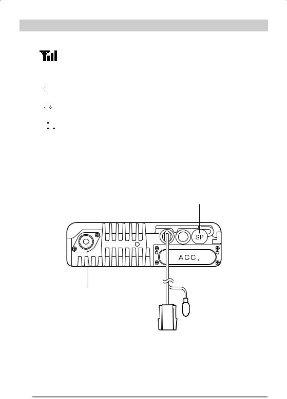
The number of bars indicates the strength of incoming |
|
|
|
signals. The antennal plus 3 bars represents a strong |
|
|
|
signal while only the antenna represents a weak signal. No |
|
|
|
antenna means no signal is present. On NXDN Trunking |
|
|
|
channels, the antenna indicator flashes when you are out of |
|
|
|
range. |
|
|
|
Appears when the Scrambler/ Encryption function is |
|
|
|
activated. |
|
|
|
|
|
|
|
Appears when the Auto Recording function on the VGS- |
|
|
|
|
|
|
|
option is activated. |
|
|
|
|
|
|
|
|
|
|
|
Appears when the Auto Reply Message is on. (The location |
|
|
|
of this icon is the same as the Auto Recording icon.) |
|
|
|
|
|
|
|
Appears when the AUX A function is activated. |
|
|
|
|
|
|
|
|
|
|
|
Appears when the AUX B function is activated. |
|
|
|
|
|
|
|
|
reAr pAnel
External speaker jack
Antenna connector
Ignition Power input 
 sense line connector
6
 Loading...