

Page 1
KENWOOD
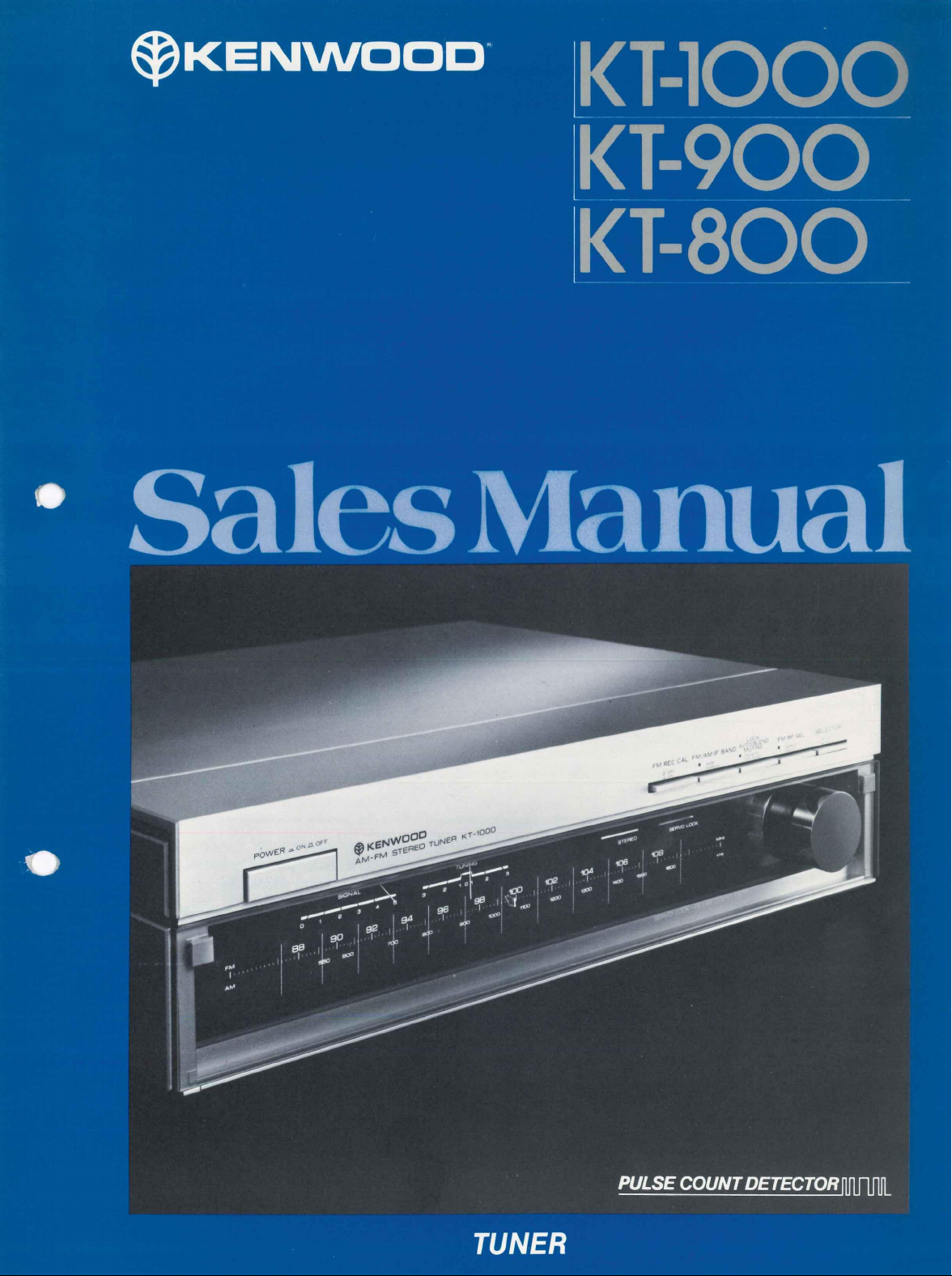
KT-IOOO
KT-900
KT-800
Sales
Manual
TUNER
PULSE COUNT DETECTOR
Page 2
Product
policy
For over three decades, Kenwood
duced innovations
name Kenwood
excellence
will testify that for
whole
lot
more
The average, non-audiophile also wants to
quality
FM and AM
budget
is
usually rather restricted.
Kenwood
has
New
in
tuner design
has thus
in
tuner technology,
to
the answer. At the top of this year's line-up
become universally recognized for
them,
the tuner
tuners than
broadcast scene, even though
Pulse
Detector
Conventional FM detection circuits using an analog method
allow
a lot of
duced
preserve
Kenwood has developed
which uses a digital method
lowing
The wave shapes
and the basic wave shape of each are converted into digital
equivalents in the form
tude.
Since only
chances
to the
is a
original
the
original characteristics
simplified explanation
of
the individual FM signals are sampled
the
basic shape
for
FM
a new
of
noise
signals.
to
pulses
has
continually intro-
and
engineering.
and
many satisfied users
is
Kenwood. But there's a
the
technology, these days.
be
in on the high
For
such customers,
Count
IC
or
distortion
In
of the FM
Pulse Count Detector
detect the FM signals.
of
how
of
equal width and ampli-
of the
order
it
works.
signals
to be
to
faithfully
signals,
are
The
the
is
intro-
IC,
Fol-
con-
the KT-1000 incorporating the latest
packaged without the frills
under in terms
900,
but still offering the superb sound quality expected
Kenwood.
automatic computer-guided tuner that combines excellent
sound quality with unrivalled ease
rundown
points and facts
verted into digital equivalents,
ples caused by noise or distortion are simply ignored — the
result
is a
free from distortion
changes
back into
same as originally input. Any noise
have affected
been completely eliminated. This system
KT-1000 and KT-900.
of
features and price range comes the KT-
Finally, there's
of
these three great
to
digital equivalent
in
temperature,
an
analog
the
signal during the detection process
to
the
help you sell
of
or
noise and remarkably stable against
humidity
signal,
the
in
tuner
technology,
attract a wider market.
totally new-style KT-800,
of
operation. Here's
new
tuners,
and the
them.
any
minor deviations
the pure original
and
age.
When converted
signal
at output
or
distortion that might
is
FM
is
exactly the
utilized
or
signal,
in the
but
A bit
of
an
a
sales
rip-
has
Direct
When there
sources competing for air
too easily picked
introducing a great
such interference, Kenwood
Conversion technique. This by-passes
stage,
are
sending signals instead directly
RF
many powerful
space,
up by the FM
deal
of
noise
has
Conversion
FM
extraneous signals are all
antenna
and
distortion.
developed a Direct
stations
and
the RF
to the
and
other
amplified,
To
eliminate
RF
amplifier
mixer stage,
where
the
intermodulation products produced
interference
than amplified. Either Direct RF Conversion
version can be selected by a
the method most suitable to the particular reception condi-
tions.
of
extraneous signals
This system
are
switch,
allowing the choice of
is
utilized in the KT-1000.
attenuated rather
or
by the
normal
con-
Page 3

Independent
Power
Supply
For
One consequence
power supplies
power supply unit
modulate
inaccuracies
below
High
In
the
tended
quality
able
Local
is
the
local oscillator frequency. This causes tuning
by
deflecting
its
optimum
past,
AM
sections
to be
neglected because
of AM
broadcasts.
to
reproduce
Oscillator
of the
that leakage from
can
level.
relatively high impedance
the +B
feed back
Kenwood engineers solved this
to the
local oscillator
the
tuned frequency above
Quality
of
FM/AM stereo tuners have
of the
generally inferior
Now,
Kenwood tuners
the
upgraded
AM
broadcast quality, with
line
of
of the
to
and
problem
the oscillator, giving the local oscillator its own independent
power supply. With
age
is
the KT-1000, this
AM Section
AM sections that are as carefully designed as FM sections.
In
the
are
fully
section.
Sample-And-Hold
MPX Circuit
by
eliminating
virtually non-existent, even
KT-1000
the
two
power supplies, noise
is
perfectly utilized.
an
IF
band selector
source itself — the + B line
at
is
100%
provided
due
to
leak-
modulation.
for
the
to
In
AM
As
with the Pulse Count Detector, Kenwood engineers have
taken advantage
cessing with
plex decoder. This circuit cleanly extracts the left and right
channel signals from
the
38
kHz subcarrier frequency. The wave peaks are
verted into digital equivalents
only the basic shape
equivalents, transient deflections
Quartz
Preset
Kenwood's quartz-PLL tuning circuit uses
oscillating frequency
quency generated by the local oscillator
tuning frequency.
automatically tune
many
as
of
the exceptional accuracy
the
introduction
of
of a
The
to any one of any
eight different
of
digital pro-
of
the Sample-and-Hold
the
composite
the waves are converted into digital
in the
in the
FM
signal carried
form
of
shape
pulses. Since
of
multi-
by
con-
waves
Synthesizer
Tuning
the
ultra-stable
quartz crystal
quartz-PLL circuit
FM or
AM
to
locked
can
combination
stations.
keep
the
to the exact
be
preset
To
preset,
fre-
to
of as
the
caused
by
noise
or
distortion
reduces
the
need
for
filtering,
nel separation, because filtering
information
ty
to
are sampled then held in a capacitor until the next peak
rives;
for precise representation
The KT-1000 employs this superior type
desired station
button
buttons
pressing
automatically tune the
the KT-800.
in
the composite
isolate left and right channel signals.
thus,
the average peak value
is
manually tuned
is
pressed, after which
may be
pressed. Whenever that station
the
station button previously selected will
station.
are
ignored. This greatly
which vastly improves chan-
can
obscure important
signal,
interfering with the
The
peak pulses
can be
instantly adjusted
of
the original 38 kHz subcarrier.
of
MPX
decoder.
in, and
any one of
This system is fully utilized
then
the
eight station
is
desired,
preset
abili-
ar-
in
Page 4

Sales Points
Key Specs
KT-1000
• Pulse Count
• Direct RF Conversion with Selector
• Dual-gate MOS-FET front-end with 5-gang tuning
capacitor
• Sample-and-Hold multiplex decoder
• Independent local oscillator power supply
• Servo-lock tuning
• High quality design AM section
• Narrow and Wide
and
AM
FM
Detector
IF
band selection
for
both
FM
KT-900
• Pulse Count
• Dual-gate MOS-FET front-end with 4-gang tuning
capacitor
• Servo-lock tuning
• High quality design AM section
• Dual-color signal strength
indicators
• Digital frequency display
• Clean reception filter
• Narrow and Wide
FM
Detector
IF
band selection
and
fine-tuning
for FM
LED
FM usable sensitivity: 23.3 dBf (8.0>V)
RF Conversion mode 10.3 dBf (1.8/A/)
mode
FM THD
Alternate channel selectivity: 65 dB
(NARROW) 45 dB (WIDE)
Stereo separation
(NARROW)
Signal-to-noise ratio: 90 dB (mono), 85 dB (stereo)
Frequency response: 15 Hz
FM usable sensitivity: 10.8 dBf (1.9^V)
FM THD
Alternate channel selectivity: 65 dB
(NARROW) 45 dB (WIDE)
Stereo separation
(NARROW)
Signal-to-noise ratio: 88 dB (mono), 83 dB (stereo)
Frequency response: 30
-0.8 dB
at 1 kHz: 0.03% (mono), 0.04% (stereo)
at
1 kHz: 60 dB (WIDE), 50 dB
to
15 kHz
at 1 kHz: 0.03% (mono), 0.04% (stereo)
at
1 kHz: 55 dB (WIDE), 47
Hz to
15 kHz +0.2 dB,
in
in
at
300 kHz
±0.5
at
300 kHz
Direct
normal
dB
dB
KT-800
New, clean panel with store-away control pocket
Quartz synthesizer tuning
8-station FM/AM preset memory bank with
nated indicator panels
Preset automatic selection
stations
FM/AM preset station random access
2-ganged AM tuning capacitor for high AM recep-
tion quality
Operational convenience and flexibility
Switchable digital display
needed
New signal strength and fine-tune display
Automatic stereo muting
of up to 8 FM or AM
of
frequency
or
illumi-
time
as
•
FM
usable sensitivity: 10.8 dBf (1.9/iV)
• FM THD
• Alternate channel selectivity: 60
• Stereo separation
• Signal-to-noise ratio: 74 dB (mono), 71 dB (stereo)
• Frequency response: 30
-2dB
at 1 kHz: 0.07% (mono), 0.09% (stereo)
dB
at
1 kHz: 50
dB
Hz to
15 kHz +0.2 dB,
Page 5

Operating Features
O Power switch
©FM
REC CAL switch.
oscillator helps achieve accurate rec-
ord level settings
©FM/AM
and Narrow band settings. Wide-band
indicator.
©
POWER
©LED
IF band, servo-lock, AM,
©AUTO/MUT
tor.
tains acceptable minimum noise level
for weak stations.
IF BAND selector.
switch
mode indicators.
Auto-muting automatically
on
and MONO mode selec-
Built-in tone
tape deck.
With Wide
Stereo, Narrow
FM.
main-
O LOCK/AUTO BLEND/MUTING switch.
Activates servo-lock system simultane-
ously with automatic muting for weak
tions
to
maintain minimum acceptable
noise
level.
©FM RF selector.
conversion,
©
IF
BAND WIDE and NARROW selector
© LOCK switch.
lock tuning and normal fine-tuning.
©REC
establishes reference
recording levels.
© FM/AM selector
Indicator
with indicator
CAL selector.
for
"Muting
Direct
or
Normal
for
Selects between servo-
Oscillator tone
for
correct tape
sta-
On"
RF
Normal
setting.
© FM/AM selector
©
Signal
©Tuning
© STEREO indicator
©SERVO-LOCK
© Digital frequency display.
©Tuning
©Signal-strength
©Touch-sensor
strength meter
meter
tuned status after hand is released from
tuning knob.
© Touch-sensor tuning knob.
May
tuning.
cates off-tuned status, green indicates
precise tuning point.
tive strength
May
tuning.
indicator.
be
deactivated
direction indicator. Red
display.
of
tuned signal.
tuning knob.
be
deactivated
Shows lock
for
normal
Shows rela-
for
normal
indi-
©TUNER
tween tuner operation
only. Power
digital clock.
© DISPLAY switch.
play of frequency
OFF/ON switch.
is
supplied constantly
o © ©
©
Selects
or
digital clock
Selects between
being
tuned
in and
©©©
©CLOCK
be
to
dis-
time.
gether with nearby Hours
buttons
©TUNING
up
buttons double
© MUTING selector with LED indicator.
ADJUST button.
to set
correct time.
buttons.
or
down
the
To
tune automatically
frequency bands. These
as
clock-adjustors.
Used
and
to-
Minutes
To activate automatic muting mode
maintain acceptable minimum noise
threshold at
© FM/AM selector
©PRESET
switch
all
times in both FM
control button.
to
activate preset station
ory
for
storage.
©
Digital frequency/time
display.
©
New vertical signal strength
display
©
8-station bank allows instant
dom access
are used with Preset control
button
With FM
TUNED,STEREO indicators.
Preset station keys.
to
preset FM
for
memory storage.
and
Preliminary
mem-
or
AM displays
and
to
AM.
ran-
AM
Page 6

Specifications
FM
TUNER SECTION
Usable Sensitivity
50dB Quieting Sensitivity
(Mono)
(Stereo)
Signal
to
Noise Ratio
(Mono) 90dB
(Stereo)
Total Harmonic Distortion
Mono 100Hz
1 000Hz 0 03%
6 000Hz 0 05% 0 3 %
15 000Hz 0 04%
50 — 10 000Hz
Stereo 100Hz 0 04%
1 000Hz 0
6,000Hz 0 06% 0.3
15 000Hz 0 4 %
50 —10 000Hz 0 12% 0.6
Capture Ratio 0 8dB
Alternate Channel Selectivity 45dB
Stereo Separation
Frequency Response
Spurious Response Ratio 120dB
Image Response Ratio 90dB
IF Response Ratio
AM Suppression Ratio 70dB
Subcarrier Product Ratio
Antenna Impedance
FM Frequency Range
Output Level Fixed
1 000Hz 60dB
50 — 10 000Hz
15 000Hz
1,000Hz
100% Modulation Variable
KT-1000
NORMAL DIRECT
10 3dBf(1
16 4dBf(3 6^V) 29 3dBf(16/jV)
37 3riRf
85dB
WIDE
0 03%
0 08%
04%
47dB
40rlR
15H7to15.0n0H7+0.5riB
110dB
73riR
75 ohms unbalanced
88MHzto 108MHz
0 75V 2 2k ohms
Oto 1.5V, 2.2kohms
8MV)
(4U,JV1
NARROW
0.04%
0 15%
0.07%
0.3%
0 3
0 3 %
1.0
2
65dB (300kHz)
50dB
35dB
23 3dBf(8 0^V)
49
firiRf
dfifiuW . 37.3dBf (40f/V) 38.4dBf (46MV)
%
%
%
%
OdB
KT-900
.
10.8dB*(1.9pV)
.
16.4dBf
(3.6JJV)
.
88dB
.
83dB
WIDE
NARROW
.
0.03%
0.04%
.
0.03%
0.15%
.
0.05%
0.4 %
0.05%
0.07%
.
0.09%
0.4 %
.
0.05%
0.3 %
.
0.04%
0.3 %
.
0.07%
0.3 %
0.5
% 1.0 %
.
0.18%
0.6 %
.
1.0dB 2.0a B
.
45dB 65dB (300kHz) 60dB
.
55dB • 47dB 50dB
.
45dB 35dB
.
37dB
30Hz to 15,000Hz + 0.2dB, -0.8dB
.
120dB
.
90dB
.
100dB 90dB
.
70dB
68dB
.
300 ohms balanced 300 ohms balanced
& 75 ohms unbalanced
.
88MHzt0
.
0.75V, 1.8k ohms 0.75V, 5.6k ohms
108MHz
KT-800
10.8dBf (1.9f/V)
16.4dBf (3.6fjV)
74dB
71dB
0.07%
0.07%
0.11
%
0.12%
0.15%
0.09%
0.14%
0.4
%
1.5dB
40dB
36dB
.. . 30Hz
to
15,000Hz + 0.2dB,
110dB
80dB
60dB
& 75 ohms unbalanced
88MHz
to
108MHz
-2dB
AM
TUNER SECTION
Usable Sensitivity
Signal to Noise Ratio
Total Harmonic Distortion 0 2%
Image Rejection
Selectivity
Output Level Fixed
400Hz30% Modulation Variable
GENERAL
Power Requirements
Power Consumption
Dimensions (W* Hx D)
Weight (Net)
Kenwood follows a policy
•
Please
direct all technical inquiries to:
TRIO-KENWOOD CORPORATION
Shionogi ShiDuya Building. 17-5. 2-chome Shibuya. Shibuya-ku. Tokyo
of
continuous advancements
A
product
10HV
.. .
52dB
.
7f)riR
30dB (WIDE), 50dB (NARROW) . 58dB
0.25V, 2.2k ohms
Oto0.5V, 2.2k ohms
fif1H7
1?0V
(U S A & Canada Model)
or 50/60Hz 110 — 120/220 — 240V..
switrhahlp
0 1HA
440*
123x388mm
(17-5/16" x 4-27/32" x 15-9/32")
6.5kg
(14.3lbs)
in
development. For this reason specifications may be changed without notice.
of
150.
Japan
.
<3.,V 18MV
.
52dB
0.4%
.
45dB
.
0.15V, 2k ohms
.
60Hz120V 60Hz 120V
.
(U.S.A. & Canada Model)
.
or50/60HZ110 — 120/220 —240V..
.
switchable
.
0.25A
.
440x78x 390mm
.
(17-5/16"X3-1/16"X15-11/32")
.
5.1kg (11.2lbs) 2.2kg (4.8lbs)
KENWOOD
ELECTRONICS, INC.
1315 E Watsoncentet Rd,
75
Seaview
Drive,
1098
North Tower
TRIO-KENWOOD
TRIO-KENWOOD
TRIO-KENWOOD
Rudolf-Braas-SIr
TRIO-KENWOOD
TRIO-KENWOOD
TRIO-KENWOOD
TRIO-KENWOOD
KENWOOD & LEE ELECTRONICS, LTD.
Wang
Kee
Building.
Carson.
Secaucus, New Jersey
Lane,
CANADA INC., 1070Javson Court Mississauga,Ontario Canada L4W
ELECTRONICS, N.V. Leuvensesteenweg 504 B-1930 Zaventem, Belgium
ELECTRONICS GmbH
20. 6056 Heusenstamm, Wes! Germany
FRANCE S.A.
SVENSKA AB. Kemistvagen
AG
(AUSTRALIA) PTY. LTD.
5th Floor,
California 90745.
5,
Boulevard Ney, 75018
34-37,
Connaught
07094.
60106,
30
10A PO
Whinng
Road,
Bensenville. Illinois
Unlerboesch 6331 Huenenberg/ZUG Switzerland
.
USA
Pans,
Box 68, S-183 21 Taby. Sweden
St ,
Artarmdn,
Central.
50dB
40dB
50dB
0.25V, 5.6k ohms
(U.S.A. & Canada Model)
or
50/60Hz 110 — 120/220
switchable
0.1A
440x52x247mm
(17-5/16"x
Hong Kong
France
NSW
2-1 /32" x 9-23/32
2V5
2064,
Australia
)
—
240V
MF479 8101007SA Printed
in
Japan
 Loading...