

Page 1

KSC-WD250T
POWERED ENCLOSED SUBWOOFER 1 page 2-6
INSTRUCTION MANUAL
CAISSON D’EXTRÊME GRAVE AMPLIFIÉ 1 page 7-11
MODE D’EMPLOI
ALTAVOZ DE SUBGRAVES CON CERRADO ALIMENTACION 1 página 12-16
MANUAL DE INSTRUCCIONES
B61-1289-00 (W) KW
Page 2
2 English
IMPORTANT SAFEGUARDS
¤ Read this page carefully to keep your safety.
¤WARNING
• Before mounting or wiring etc., be sure to remove the wire from the battery
minus terminal.
(Not doing so can cause shorts or fires.)
• When extending the ignition, battery, or ground wires, make sure to use
automotive-grade wires or other wires with a 0.75mm² (AWG18) or more to
prevent wire deterioration and damage to the wire coating.
• To prevent a short circuit, never put or leave any metallic objects (such as
coins or metal tools) inside the speaker.
• Abnormal smell – In the event the unit generates smoke or abnormal smell,
immediately switch the power OFF. After this, please contact your dealer or
nearest service station as soon as possible.
• Modification – Do not attempt to open or modify the unit, for this could
cause fire hazard or malfunction.
• Suffocation – After taking the unit out of the polyethylene bag, be sure to
dispose of the polyethylene bag out of the reach of children. Otherwise, they
may play with the bag, which could cause hazard of suffocation.
FCC WARNING
This equipment may generate or use radio frequency energy. Changes or
modifications to this equipment may cause harmful interference unless the
modifications are expressly approved in the instruction manual. The user could
lose the authority to operate this equipment if an unauthorized change or
modification is made.
¤CAUTION
• Do not install the speaker in a spot exposed to direct sunlight or excessive
heat or humidity.
• Water and moisture – Do not install the speakers in locations which may be
subject to water or moisture.
• Dust and unstable locations – Do not install the speakers in unstable
locations or locations subject to dust.
• If the fuse blows, after checking to see if the wiring cord has shorted, be sure
to replace with the stipulated size (amperage) fuse as displayed on the fuse
box.
(Using fuses other than the stipulated size can cause fires.)
To replace the fuse, refer to the vehicle instruction manual.
• To prevent a short circuit when replacing a fuse, disconnect the wiring harness
at first.
• Do not use gasoline, naphtha, or any type of solvent to clean the speaker.
Clean by wiping with a soft, dry cloth.
• Do not connect cables and leads to both RCA cable input jacks and the
speaker input terminals simultaneously, for this may cause malfunction or
damage.
• When making a hole under a seat, inside the trunk, or somewhere else in the
vehicle, check that there is nothing hazardous on the opposite side such as
a gasoline tank, brake pipe; or wiring harness, and be careful not to cause
scratches or other damage.
• For ground wire mounting, do not fasten the wire to an airbag, steering or
brake line system or other critical safety unit bolts or nut.
(Can cause accidents.)
• When mounting, be sure to mount in a place that will not interfere with
driving or be dangerous to passengers during sudden braking etc.
(Cause of injury or accidents.)
• After installing the unit, check to make sure that electrical equipment such as
the brake lamps, turn signal lamps and windshield wipers operate normally.
Before installing the speaker or making any connections, please
read all of this instruction manual carefully, to make sure that
you perform these operations correctly.
■ For your records
Record the serial number, found on the right side of the unit, in the spaces
designated on the warranty card, and in the space provided below. Refer to
this model’s name and serial number whenever you call upon your KENWOOD
dealer for information or service on this amplifier.
Model KSC-WD250T Serial number ________
■ Safety Precautions
In a situation where the car has been left in direct sunlight with its windows
closed and the temperature inside the car has risen to a very high level, switch
on the air conditioner or drive the car for awhile with the windows open before
operating the car stereo. Do not operate the car stereo until the temperature
inside the car has dropped to a normal level.
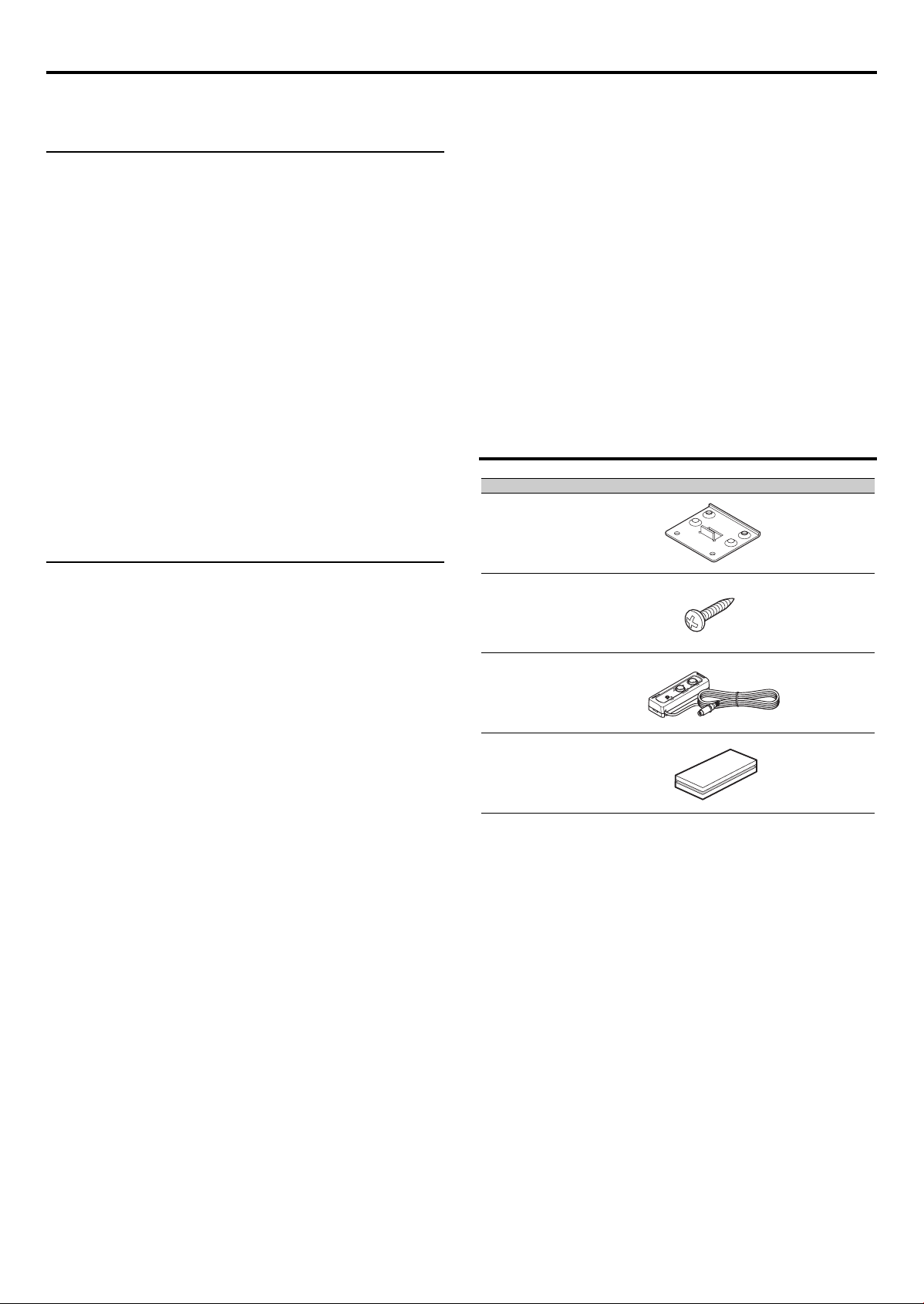
Parts included
No. Part Name Outside Shape Quantity
1
2
3
4
Tap screw
(Ø5 × 22mm)
Remote control unit
Velcro tape
Bracket
(6m)
4
16
1
1
Page 3
English 3
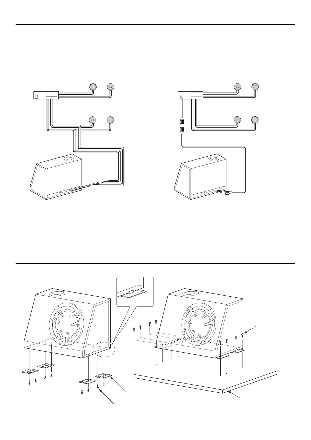
Connection
To enhance the bass sound of your car stereo system, this unit can be connected to it as shown in the following examples.
• Do not connect this speaker to other amplifiers. Otherwise, it could damage amplifiers.
■ Examples of applications
• General connection
CENTER UNIT
Front speaker
Rear speaker
• Connection to center unit with non-fader (subwoofer control)
Front speaker
CENTER UNIT
Rear speaker
RCA cord
( Commercially
available parts)
Installation
1 Bracket × 4
2 Tap screw
(Ø5 × 22mm) × 8
2 Tap screw
(Ø5 × 22mm) × 8
Installation board, etc.
(thickness : 25 mm or more)
Page 4
4 English
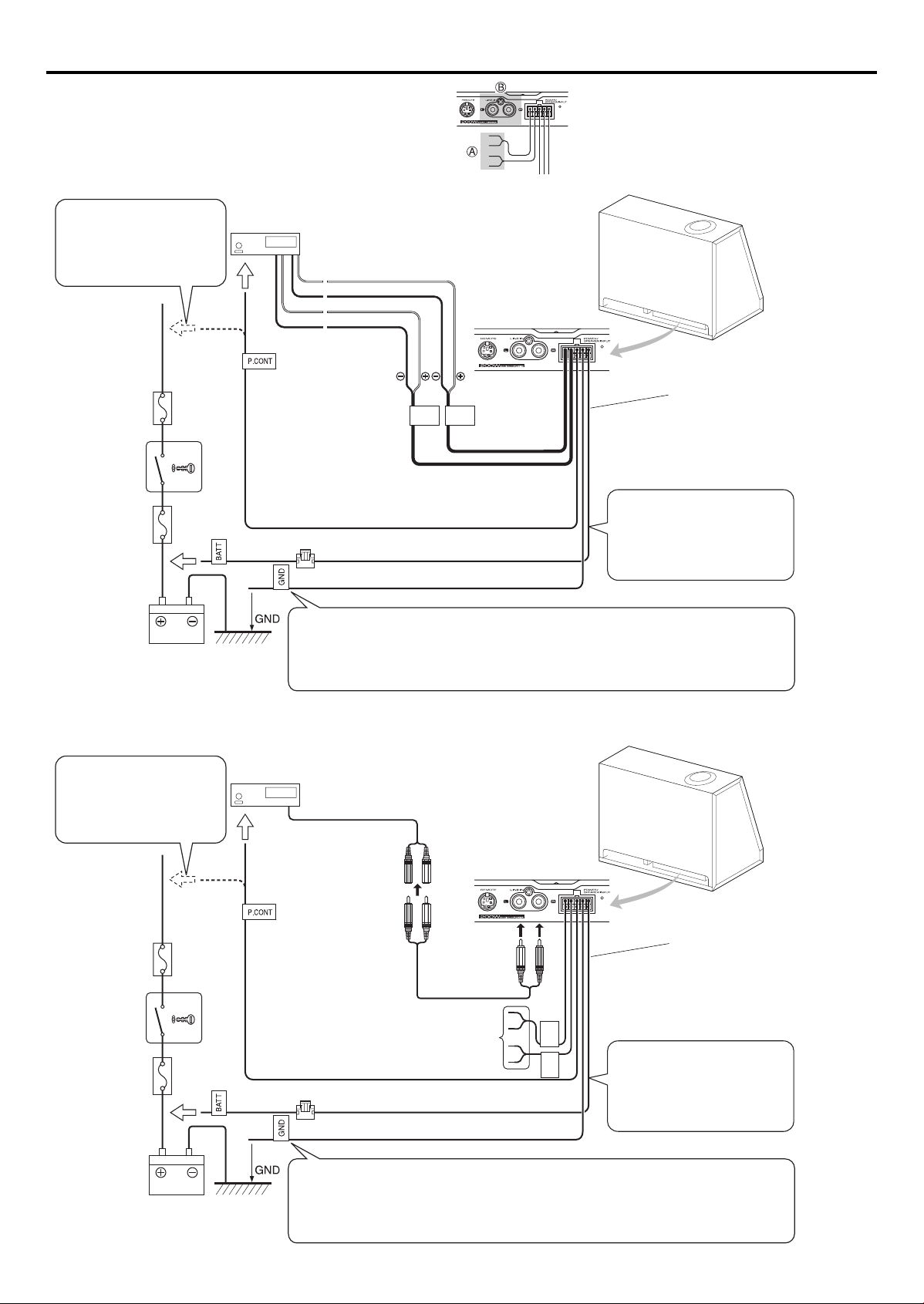
Examples of Connections
REAR
SP. L
INPUT
REAR
SP. R
INPUT
Caution: ––––––––––––––––––––––––––––––––––––––––––––––––––––––––
Under any circumstances, never apply inputs to the terminals A and B
simultaneously.
––––––––––––––––––––––––––––––––––––––––––––––––––––––––––––––––
■ General connection
• If there is no power control
terminal in the center unit,
connect the blue/white wire to
the accessory line (ignition key
switch ACC position line).
Car fuse box
Ignition key
switch
Car fuse box
(Main fuse)
Battery
CENTER UNIT
To the power control
terminal
Blue / white
Fuse 5A × 2
Caution
• Connect the black lead wire ground terminal directly with a screw to an unpainted metal part of
the vehicle. Turning the power ON without connecting this terminal is linked to damage of the
stereo system. Be sure to connect it.
Also, painted metal panels etc., are not grounded and will not function correctly. Be careful.
Purple
Purple / Black
Green
Green / Black
Yellow
Black
10-pin connector cord
• If buzzing noise is heard from
the speakers when the engine is
running, attach a line noise filter
(sold separately) to the power
lead.
■ Connection to center unit with non-fader (subwoofer control)
• If there is no power control
terminal in the center unit,
connect the blue/white wire to
the accessory line (ignition key
switch ACC position line).
Car fuse box
Ignition key
switch
Car fuse box
(Main fuse)
CENTER UNIT
To the power control
terminal
Blue / white
Unused terminal
Cover unused terminals with insulation
tape to avoid short circuits.
Fuse 5A × 2
SUBWOOFER OUT
Yellow
Black
RCA cord
( Commercially
available parts)
REAR
REAR
10-pin connector cord
SP. R
INPUT
SP. L
INPUT
• If buzzing noise is heard from
the speakers when the engine is
running, attach a line noise filter
(sold separately) to the power
lead.
Battery
Caution
• Connect the black lead wire ground terminal directly with a screw to an unpainted metal part of
the vehicle. Turning the power ON without connecting this terminal is linked to damage of the
stereo system. Be sure to connect it.
Also, painted metal panels etc., are not grounded and will not function correctly. Be careful.
Page 5
English 5
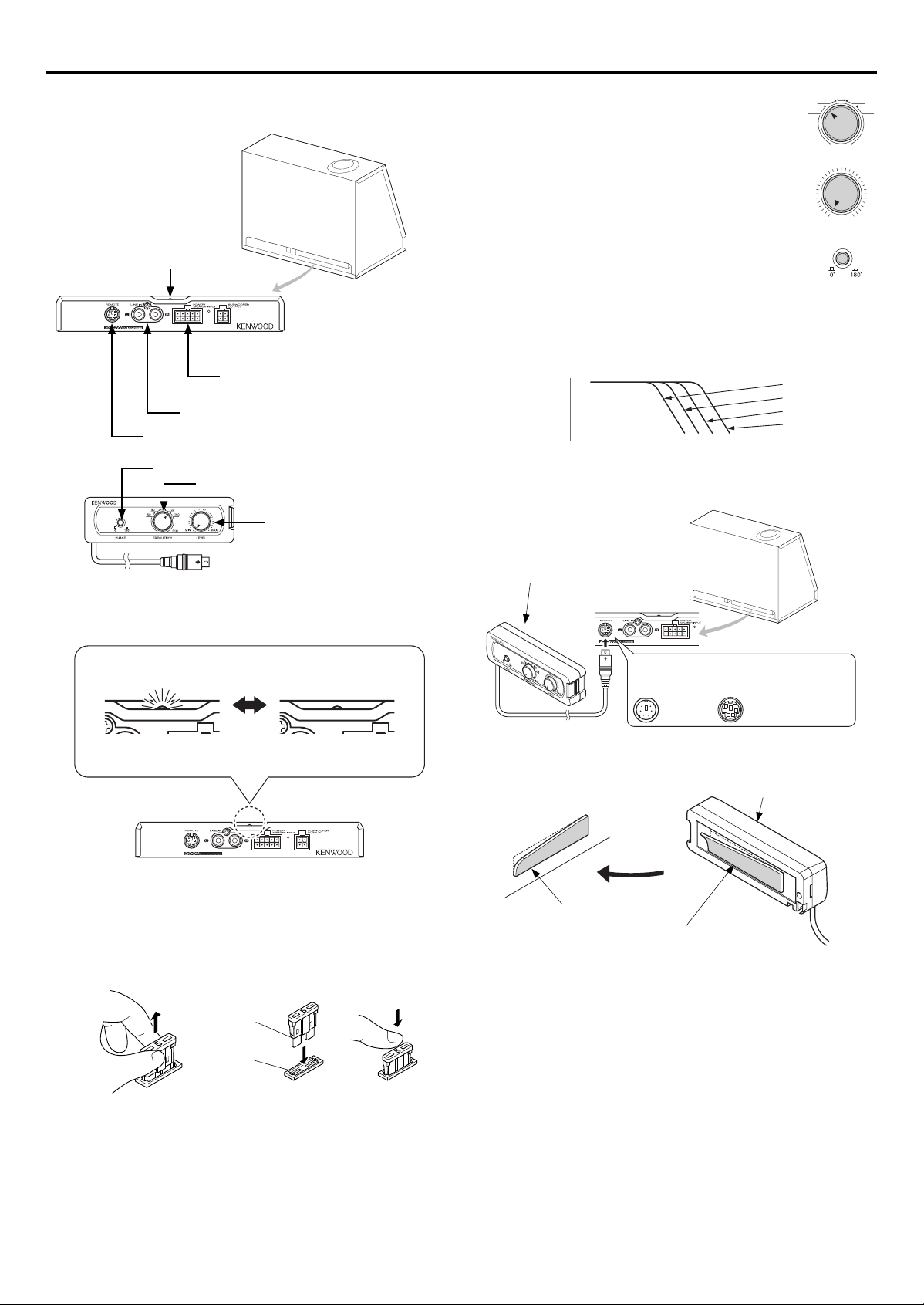
Operation
FREQUENCY
(Hz)
50 150
80 100
■ Name of each part
Power indicator
REMOTE terminal
PHASE
Power Supply/Control Input/Terminal (for
Speaker Cords)
LINE IN terminal (RCA pin jack)
FREQUENCY
LEVEL
■ Basic operation
1. Set the crossover frequency.
Turn the LOW PASS FREQUENCY control knob to adjust the
balance between the bass from the rear speakers and the bass
from this unit as desired.
2. Adjust the low frequency level.
Turn the knob to the desired level.
MIN MAX
3. Adjust the low frequency phase.
The low frequency tone may be variable depending on the
position of the unit, its orientation or the crossover frequency. This
can be adjusted by changing the position of the PHASE switch. Set
this switch to either position according to your liking.
● Crossover frequency: The frequency at which the high range
is cut off.
MAX
LEVEL
MIN
LOW HIGH
FREQUENCY
50Hz
80Hz
100Hz
150Hz
● Connecting the remote control unit
LEVEL
PHASE
■ Power Indicator
Blue glows
[Power ON ]
Light is OFF
[Power OFF ]
■ Fuse exchange
Exchange with the specified capacity fuse.
Removal: Grasp with your fingers and pull up.
Insertion: Insert the fuse gently into the fuse holder and push in all
Caution: ––––––––––––––––––––––––––––––––––––––––––––––––––––––––
Be sure to replace with same capacity (amperage) as displayed on the fuse.
This product is 5A.
––––––––––––––––––––––––––––––––––––––––––––––––––––––––––––––––
the way with your finger.
Fuse
Fuse holder
Replacement fuse 5A
3 Remote control unit
When connecting the cord, align the jacks
as shown below.
Mini-Din REMOTE CONTROL
● Installing the remote control unit
Install the remote control unit on the vehicle by the provided Velcro tape.
3 Remote control unit
Vehicle
4 Velcro tape
(Hook surface)
Caution: ––––––––––––––––––––––––––––––––––––––––––––––––––––––––
Install the remote control unit in a position that does not come in the way of
driving operations.
Avoid installing it in a place subject to direct sunlight or direct hot wind
from the heater.
Remove dirt from the installation position before attaching the Velcro tape.
––––––––––––––––––––––––––––––––––––––––––––––––––––––––––––––––
4 Velcro tape
(Loop surface)
Rear panel
Page 6

Troubleshooting Guide
Often, what appears to be a malfunction is due to user error. Before calling for service, please consult the following table.
Problem Cause Remedy
• Check the (+)/(-) polarity of the power cord and that the cords are
• The fuse is blown.
Power cannot be turned on
(the POWER indicator does
not light).
No sound
Sound quality is bad
(sound is distorted).
Unable control • Remote control cord is not connected. • Connect remote control cord to remote control terminal.
The sound is unnatural.
• The power supply pin (yellow) of the 10-pin connection cord is
not connected.
• The power control pin (blue) of the 10-pin connection cord is
not connected.
• The 10-pin connector is not plugged in completely.
• The grounding pin (black) of the 10-pin connection cord is not
connected.
• The negative (-) cable of the car battery is disconnected.
• The attenuator of the center unit is set to ON. • Switch the attenuator OFF.
• The LEVEL control is set to the MIN position. • Increase the volume to an optimum level.
• The speaker cords are connected improperly.
• Connection terminals are connected improperly. • Insert the connectors or jacks all the way in to the terminals.
• The LEVEL control is set to the MAX position. • Set the volume to an optimum level.
• The speaker cords are connected with incorrect positive (+)/
negative (-) polarity.
• The grounding pin (black) of the 10-pin connection cord is
poorly contacted.
not shorted, then replace with a fuse with the rated capacity.
• Re-connect the cords correctly by referring to the connection
example (on page 4).
• Connect the cord correctly by referring to the connection example
(on page 4).
• Check the connections of all cords, then connect the (-) cable to
the battery.
• Insert the connector all the way in.
• Attach the grounding terminal to the metallic section of the
vehicle (not a coated surface) by tightly screwing it.
• Check the connections of all cords, then connect the (-) cable to
the battery.
• Connect the cords correclty by referring to the connection
example (on page 4).
• Connect the cords correctly by referring to the connection
example (on page 4).
• Attach the grounding terminal to the metallic section of the
vehicle (not a coated surface) by tightly screwing it.
Specifications
The following ratings and design are subject to change without notice.
[Amp unit]
Maximum output ...........................................................................................................................................200 W
Frequency Response (System) ................................................................................................................30 – 150 Hz
S/N ratio .............................................................................................................................................................. 85 dB
Low Pass Filter Frequency ......................................................................................................................... 50 Hz, 80 Hz, 100 Hz, 150 Hz (4 steps)
Phase ..................................................................................................................................................................0°, 180°
Sensitivity/ Input Impedance (RCA pin jack) ..................................................................................210 mV / 10 kΩ
Sensitivity/ Input Impedance (Speaker input) ...............................................................................4.2 V / 1 kΩ
Power .................................................................................................................................................................. DC 14.4 V (Operational range 10.5 – 16 V)
Maximum current consumption ...........................................................................................................10 A
Fuse capacity ....................................................................................................................................................5 A × 2
External size ......................................................................................................................................................Width 195 mm × height 30 mm × depth 155 mm
..................................................................................................................................................................(7-11/16 ” × 1-3/16 ” × 6-1/8 ”)
Weight .................................................................................................................................................................800 g (1.8 lb)
[Speaker unit]
Impedance ........................................................................................................................................................0.75 Ω (Dual voice coil)
Woofer .................................................................................................................................................................10 inch Cone type
[Amp unit] + [Speaker unit]
Net weight .........................................................................................................................................................11.1 kg (24.5 lb)
External size ......................................................................................................................................................Width 432 mm × height 363.5 mm × depth 226 mm
(17 ” × 14-5/16 ” × 8-7/8 ”)
6 English
Page 7

AVERTISSEMENTS IMPORTANTS
¤ Lire attentivement cette page pour votre sécurité.
¤ATTENTION DANGER
• Avant d'effectuer le montage ou le câblage, etc., assurez-vous de débrancher
la borne négative de la batterie.
(Dans le cas contraire, vous risquez de déclencher un court-circuit ou un
incendie)
• Si vous devez rallonger les câbles d’allumage, de batterie et de mase, utilisez
des câbles pour véhicules automobiles ou des câbles ayant au moins une
section de 0,75 mm² (AWG 18) de façon à éviter un endommagement du
câble ou de son isolant.
• Pour éviter tout court-circuit, n’introduisez jamais un objet métalliaque (pièces
de monnaie, outils) dans un haut-parleur.
• Odeur anormale – Dans le cas oû l’appareil produit de la fumée ou une
odeur anormale, couper immédiatement l’alimentation. Contacter ensulte
votre concessionnaire ou centre de service plus proche le plus rapidement
possible.
• Modiffication – Ne pas essayer de démonter ni de modifier l’apparell car ceci
risque de provoquar un risque d’incendie ou un fonctionnement incorrect.
• Etouffement – Après avoir retré l’appareil du sac de polyéthylàne, bien placer
ce dernier hors de la portée des enfants. S’ils jouent avec ce sac, un risque
d’étouffement est possible.
¤ATTENTION
• N’installez pas le haut-parleur dans un endroit directement exposé au soleil ou
à une humidité ouchaleur excessives.
• Esu et humidité – Ne pas installer les haut-parieurs dans des endroits où ils
peuvent être exposés à de l’eau ou à l’humidité.
• Poussière et endroits instables – Ne pas installer les haut-parteurs dans de
endroits instables ou exposés à de la poussière.
• Si le fusible grille, assurez-vous de le remplacer, après avoir vérifié que le
câblage n’est pas en court-circuit, par un fusible du calibre spécifié (ampérage)
sur le boîtier.
(L’utilisation de fusible de calibre supérieur peut causer un incendie)
Pour le remplacement de fusible, consultez le manuel d’utilisation du véhicule.
• Avant de remplacer le fusible et pour éviter tout court-circuit, débranchez le
faisceau.
• N’utilisez ni essence, ni pétrole ni aucun solvant pour nettoyer le haut parleur.
Utilisez un chiffon doux et sec.
• Ne reliez pas les câbles et les conducteurs simultanément aux prises d’entrées
Cinch et aux bornes d’entrées des hautparleurs car cela peut entraîner une
anomalie de fonctionnement.
• Avant de percer un t rou sous un siège, dans le coffre et, d’une manière
générale, en n’importe quel point du véhicule, assurez-vous que vous
pouvez le faire sans danger et que votre intervention ne conduira pas à
l’endommagement du réservoir de carburant, d’une canalisation de frein ou
d’un faisceau électrique; veillez également à ne pas effectuer de rayures ou
d’autres dommages inutiles.
• Pour le raccordement à la masse, ne pas fixer le fil à un airbag, au système de
direction, à une ligne du système de freinage ou à tout autre boulon ou écrou
critique en terme de sécurité.
(Risque d’accident).
• Pour l’installation, choisissez un emplacement qui ne présente aucune
gêne pour la conduite du véhicule ou un danger pour les passagers lors de
freinages soudains, etc.
(Risque de blessure ou d’accident)
• Apès installation assurez-vous que les équipements électriques tels que
les feux stop, les feux clignotants et les essuieglace fonctionnent toujours
normalement.
Avant déffectuer l’installation ou tout raccordement de hautparleur, lire ces instructions de montage avec soin et en entier
de manière à procéder correctement.
■ Pour votre propre référence
Notez le numéro de série, situé sur le côté droit de l’appareil, dans les espaces
prévus à cet effet sur la carte de garantie ainsi que dans l’espace fourni cidessous. Se référer à ce nom de modè et à celui de série dans le cas où vous
consultez votre concessionnaire KENWOOD pour des informations ou des
réparations de cet amplificateur.
KSC-WD250T Numéro de série ________
Modèle
■ Précautions pour la sécurité
Dans les cas où la voiture est laissée directement au soleil avec les vitres fermées
et que la température à l’intérieur de la voiture s’est élevée à un très haut niveau,
mettre le climatiseur en circuit ou conduire pendant un moment avec les
vitres ouvertes avant de faire fonctionner l’autostéréo. Ne pas faire fonctionner
l’autostéréo avant que la température dans la voiture ne soit retournée à un
niveau normal.
Fournitures
No. Désignation des pièces Forme extérieure Quantité
1
Vis auto taraudeuse
2
Télécommande (6m)
3
4
Support
(Ø5 × 22mm)
Bande Velcro
4
16
1
1
Frençais 7
Page 8

8 Frençais
Connexions
Pour mettre en valeur les sonorités graves de la chaîne stéréo de votre voiture, cet appareil peut raccorder comme indiqué dans les exemples ci-dessous.
• Ne raccordez pas cette enceinte à d'autres amplificateurs. Vous pourriez endommager les amplificateurs.
■ Exemples d'utilisations possibles
• Raccordements de l'ensemble
Haut-parleurs avant
• Connexion à l'unité centrale sans atténuateur (contrôle du
subwoofer)
Haut-parleurs avant
Unité centrale
Haut-parleurs arrière
Unité centrale
Haut-parleurs arrière
Câble RCA
( disponible dans
le commerce)
Installation
1 Support × 4
2 Vis auto taraudeuse
(Ø5 × 22mm) × 8
2 Vis auto taraudeuse
(Ø5 × 22mm) × 8
Tableau d'installation, etc.
(épaisseur: 25 mm ou plus)
Page 9

Frençais 9
REAR
SP. L
INPUT
REAR
SP. R
INPUT
Exemples de connexions
Attention: ––––––––––––––––––––––––––––––––––––––––––––––––––––––
N’appliquez en aucun cas les entrées simultanément aux bornes A et B.
––––––––––––––––––––––––––––––––––––––––––––––––––––––––––––––––
■ Raccordements de l'ensemble
• Si l'unité centrale ne comporte
pas de borne de commande
d'alimentation, connectez les
fils bleu et blanc à la ligne pour
accessoires (alimentée lorsque la
clef de contact est placée sur ACC).
Boîte de fusible
Commutateur
à clef
Boîte de fusible
(Fusible principal)
Batterie
Unité centrale
Vert / Noir
Borne de commande
d'alimentation
Bleu / Blanc
Fusible 5A × 2
Attention
• Connectez le fil de masse noir avec une vis directement sur une partie métallique non peinte du
véhicule. Toute mise sous tension sans connecter ce fil de masse risque d'endommager le système
stéréo. N'oubliez surtout pas de le connecter.
La peinture, etc., risque de ne pas produire une connexion appropriée à la masse et d'empêcher le
fonctionnement correct de l'appareil. Prenez les précautions appropriées.
Mauve
Mauve / Noir
Vert
Jaune
Noir
Cordon de connection à 10
broches
• Si un ronronnement se fait
entendre par les haut-parleurs
lorsque le moteur tourne,
monter un filtre antiparasite de
ligne (vendu séparément) sur le
conducteur d'alimentation.
■ Connexion à l'unité centrale sans atténuateur (contrôle du subwoofer)
• Si l'unité centrale ne comporte
pas de borne de commande
d'alimentation, connectez les
fils bleu et blanc à la ligne pour
accessoires (alimentée lorsque la
clef de contact est placée sur
Boîte de fusible
Commutateur
à clef
Boîte de fusible
(Fusible principal)
Batterie
ACC).
Unité centrale
Borne de commande
d'alimentation
Bleu / Blanc
Voir Raccordement
Recouvrez les bornes non utilisées avec
une bande adhésive isolante pour éviter
les courts-circuits.
Fusible 5A × 2
Attention
• Connectez le fil de masse noir avec une vis directement sur une partie métallique non peinte du
véhicule. Toute mise sous tension sans connecter ce fil de masse risque d'endommager le système
stéréo. N'oubliez surtout pas de le connecter.
La peinture, etc., risque de ne pas produire une connexion appropriée à la masse et d'empêcher le
fonctionnement correct de l'appareil. Prenez les précautions appropriées.
SUBWOOFER OUT
Jaune
Noir
Câble RCA
( disponible dans
le commerce)
REAR
REAR
Cordon de connection à 10
broches
SP. R
INPUT
• Si un ronronnement se fait
SP. L
INPUT
entendre par les haut-parleurs
lorsque le moteur tourne,
monter un filtre antiparasite de
ligne (vendu séparément) sur le
conducteur d'alimentation.
Page 10

10 Frençais
Fonctionnement
FREQUENCY
(Hz)
50 150
80 100
■ Désignation de chaque pièce
Indicateur de puissance
Borne d'alimentation/commande d'alimentation
d'entrée (pour haut-parleurs)
Borne LINE IN (Jack RCA)
Borne REMOTE
PHASE
FREQUENCY
LEVEL
■ Fonctionnement de base
1. Régler la fréquence de recouvrement.
Tourner le bouton de réglage de la fréquence du filtre passe-bas
(LOW PASS FREQUENCY) pour régler à volonté la balance entre
les basses de haut-parleurs arrière et les basses de cet appareil.
2. Régler le niveau des basses fréquences.
Tourner le bouton au niveau souhaité.
MIN MAX
3. Mettre les basses fréquences en phase.
La tonalité de basse fréquence peut être variable en fonction de
la position de l’appareil, de son orientation ou de sa fréquence de
recouvrement. Elle est réglable par la position du commutateur
PHASE. Choisir le position de ce commutateur selon son goût.
● Fréquence de recouvrement: C'est la fréquence à laquelle la
plage de réglage haute est coupée.
MAX
LEVEL
MIN
LOW HIGH
FREQUENCY
50Hz
80Hz
100Hz
150Hz
● Raccordement de la télécommande
LEVEL
PHASE
■ Indicateur de puissance
S'allume en Bleu
[Power ON ]
Le voyant est éteint
[Power OFF ]
■ Remplacement de fusible
Remplacez le fusible défectueux par un autre du calibre spécifié.
Retraitl: Attrapez-le avec les doigts et tirez vers le haut.
Insertion: IInsérez avec précautions le fusible dans son support et
Attention: ––––––––––––––––––––––––––––––––––––––––––––––––––––––
Ne remplacer le fusible que par un autre du même calibre (ampérage)
marqué dessus. 5 A dans ce cas.
––––––––––––––––––––––––––––––––––––––––––––––––––––––––––––––––
appuyez avec le doigt pour qu'il soit introduit à fond.
Fusible
Support de fusible
Fusible de rechange de 5 A
3 Télécommande
Pour connecter le cordon, veuillez aligner les
jacks comme indiqué ci-dessous.
Mini-Din Télécommande
● Installation du boîtier de télécommande
Installez le boîtier de télécommande au moyen des morceaux de bande
Velcro fournis.
3 Télécommande
Véhicule
4 Bande Velcro
(Surface du
crochet)
Attention: ––––––––––––––––––––––––––––––––––––––––––––––––––––––
Installez le boîtier de télécommande dans un endroit tel qu'il ne gêne en
rien la conduite.
Evitez d'installer le boîtier de télécommande dans un endroit où il serait
exoposé à la lumière du soleil ou à l'air chaud du radiateur.
Nettoyez la surface avant de poser la bande Velcro.
––––––––––––––––––––––––––––––––––––––––––––––––––––––––––––––––
4 Bande Velcro
(Surface de la
boucle)
Panneau
arrière
Page 11

Frençais 11
Guide de Depannage
Bien souvent, ce qui semble un mauvais fonctionnement de l'appareil est dû à une manipulation erronée de l'utilisateur. Avant de faire appel au
réparateur, passer la tableau suivant en revue.
Problème Cause Remedy
• Le fusible est grillé.
L'appareil ne peut pas être
mis sous tension (le témoin
POWER ne s'éclaire pas).
Pas de son
La qualité sonore
estinsuffisante (le son est
déformé)
Commande impossible • Le cordon de la télécommande n'est pas raccordé.
Les sons ne sont pas
naturels.
• La broche d'alimentation (jaune) du câble à 10 broches n'est
pas raccordée.
• La broche de commande d'alimentation (bleue) du câble à 10
broches n'est pas raccordée.
• Le connecteur à 10 broches n'est pas complétement connecté
• La broche de masse (noire) du câble à 10 broches n'est pas
raccordée.
• Le câble négatif (-) de la batterie est débranché.
• L'atténuateur de l'appareil central est sur ON. • Mettez hors service l'atténuateur.
• La commande LEVEL est sur la position MIN. • Augmentez le niveau de sortie jusqu'à la valeur potimale.
• Les cordons de liasion aux haut-parleurs ne sont pas
convenablement raccordés.
• Les bornes ne sont pas convenablement raccordées. • Introduisez à fond les connecteurs et les prises.
• La commande LEVEL est sur la position MAX. • Réglez le niveau de sortie à la valeur optimale.
• Les cordons de liaison aux haut-parleurs sont incorrectement
reliés du point de vue des polarités positive (+) et négative (-).
• La broche de masse (noire) du câble à 10 broches n'établit pas
un bon contact.
• Contrôlez les polarités (+) et (-) des cordons et assurez-vous que
les cordons ne sont pas en court-circuit, puis remplacez le fusible
par un fusible du même calibre.
• Rebranchez les cordons comme il convient en vous reportant à
l'exemple de connexion (page 9).
• Branches le cordon comme il convient en vous reportant à
l'exemple de connexion (page 9).
• Vérifiez les raccordements de tous les cordons puis reliez le câble
(-) à la batterie.
• Introduisez à fond le conncteur.
• Fixez la borne de masse à une partie métallique du véhicule (une
partie non peinte) par un serrage soigneux.
• Vérifiez les raccordements de tous les cordons puis reliez le câble
(-) à la batterie.
• Branchez les cordons comme il convient en vous reportant à
l'exemple de connexion (page 9).
• Raccordez le cordon de la télécommande à la prise de
télécommande.
• Brachez les cordons comme il convient en vous reportant à
l'exemple de connexion (page 9).
• Fixez la borne de masse à une partie métallique du véhicule (une
partie non peinte) par un serrage soigneux.
Specifications
La conception et les caractéristiques suivantes peuvent être modifiées sans préavis.
[Unité d'amplification]
Puissance maximum ....................................................................................................................................200 W
Réponse en fréquence (Chaîne) ............................................................................................................30 – 150 Hz
Rapport signal/bruit .....................................................................................................................................85 dB
Fréquence du filtre passe-bas .................................................................................................................50 Hz, 80 Hz, 100 Hz, 150 Hz (4 niveaux)
Phase ..................................................................................................................................................................0°, 180°
Sensibilité/ Impédance d'entrée (Jack mâle RCA) .......................................................................210 mV / 10 kΩ
Sensibilité/ Impédance d'entrée (Entrée enceinte acoustique) ........................................... 4,2 V / 1 kΩ
Alimentation .....................................................................................................................................................14,4 VC (Intervalle de fonctionnement 10,5 à 16 V)
Consommation maximale .........................................................................................................................10 A
Calibre du fusible ........................................................................................................................................... 5 A × 2
Dimensions hors tout .................................................................................................................................. L 195 mm × H 30 mm × P 155 mm
..................................................................................................................................................................(7-11/16 ” × 1-3/16 ” × 6-1/8 ”)
Poids ..................................................................................................................................................................800 g
[Enceinte]
Impédance ........................................................................................................................................................0,75 Ω (Double bobine mobile)
Basses ..................................................................................................................................................................Type à cône 10 pouces
[Unité d'amplification] + [Enceinte]
Poids net .............................................................................................................................................................11,1 kg
Dimensions hors tout .................................................................................................................................. L 432 mm × H 363,5 mm × P 226 mm
..................................................................................................................................................................(17 ” × 14-5/16 ” × 8-7/8 ”)
Page 12

12 Español
AVISOS IMPORTANTES
¤ Para su seguridad, lea con atención esta página.
¤ADVERTENCIA
• Antes de realizar el montaje o el cableado, etc., asegúrese de retirar el cable
del terminal negativo de la batería.
(De lo contrario pueden producirse cortocircuitos o incendios).
• Cuando extienda los cables de encendido, batería o masa, asegúrese de
utilizar cables para uso en automóviles u otros cables de 0,75 mm² (AWG 18)
o más, para impedir que se deteriomen los propios cables o se desgaste el
revestimiento.
• Para impedir cortocircuitos, nunca ponga o deje objetos metálicos (tales como
monedas o herramientas metálicas) en el interior de un altavoz.
• Olcr anormal – En el caso de que la unidad genere humo o un ruldo anormal,
desconecte inmediatamenta la slimentación. Después, consulte con su
conceslonario o centro de reparaciones más cercano tan pronto como sea
posible.
• Modificación – No trate de abrir ni modificar la unidad porque podría
producirse un peligro de incendio o una avería.
• Asflxia – Después de sacer la unidad de la bolsa de polletileno, asegúrese de
poner la bolsa de polletileno donde no puedan alcanzarla los niños. De otra
forma, éstos podrfan jugar con la bolsa y se podría producir un pellgro de
asflxia.
¤PRECAUCIÓN
• No instale el altavoz en un lugar expuesto a la luz solar directa o a un calor o
humedad excesivo.
• Agua y humedad – No instale los altavoces en lugares someticios al agua o a
la humedad.
• Polvo y ubicaciones inestabies – No instale los altavoces en lugares
inestabies ni en lugares donde haya polvo.
• Si saltara el fusible, después de comprobar si el cable ha sufrido un
cortocircuito, asegúrese de reemplazarlo por un fusible de la capacidad
(amperaje) estipulada, tal como se indica en la caja de fusibles.
(El uso de fusibles de una capacidad que no sea la estipulada, puede ser
motivo de incendios).
Para cambiar el fusible, remítase al manual de instrucciones del vehículo.
• Para impedir un cortocircuito cuando sustituya un fusible, desconecte primero
el conjunto de los cables.
• No utilice gasolina, naftalina u otro tipo de disolvente para limpiar el altavoz.
Limpielo pasando un panño blando y seco.
• No conecte simultáneamente cables y conductores a ambas tomas de entrada
de cables RCA y a los terminales de entrada del altavoz, porque esto puede
causar fallos en el funcionamento o daños.
• Cuando haga un agujero debajo de un asiento, en el portamaletas o en
cualquier otro punto del vehículo, compruebe que no haya nada peligroso
al otro lado como, por ejemplo, un deposito de gasolina, tubería de frenos
o conjuntos de cables, y tenga cuidado para no dejar marcas y hacer otros
daños.
• Para el montaje de tierra no sujete el cable a un airbag, la dirección o el
sistema de frenado ni a ningún tornillo o tuerca críticos de la unidad de
seguridad.
(Puede producir accidentes.)
• Durante el montaje, asegúrese de realizar el mismo en un sitio que no
interfiera con la conducción o que resulte peligroso para los pasajeros al frenar
bruscamente, etc.
(Causa de lesiones o accidentes).
• Después de instalar la unidad, asegúrese de que el equipo eléctrico tal
como luces de frenos, luces de intermitentes y limpiaparabrisas funcionen
normalmente.
Antes de instalar el altavoz o hacer cualquier conexión,
lea cuidadosamente todo este manual de instrucciones
para asegurarse de realizar correctamente las operaciones
necesarias.
■ Para su conocimiento
Registre el número serial, que se encuentra en el lado derecho de la unidad,
en los espacios designados para este en la tarjeta de garantía, y en el espacio
suministrado a continuación. Mencione el nombre y ei número de serie de este
modelo cuando quiera que acuda a su concesionario KENWOOD para pedirle
información o solicitarle réparaciones de este amplifier.
Modeio
KSC-WD250T Número de serie ____________
■ Precauciones de seguridad
Cuando el automóbil haya sido dejado bajo la luz solar directa con sus ventanas
cerradas y la temperatura interior haya alcanzado un nivel muy alto, encienda
el acondicionador de aire o conduzca el automóvil durante un rato con las
ventanas abiertas antes de utilizar el equipo estéreo del automóvil. No utilice
el equipo estéreo del automóvil hasta que la temperatura en el interior haya
disminuido hasta un nivel normal.
Piezas incluidas
No. Nombre de pieza Forma externa Cantidad
1
2
3
4
Abrazadera
Tornillo de cubierta
(Ø5 × 22mm)
Unidad de mando a
distancia (6m)
Cinta Velcro
4
16
1
1
Page 13

Español 13
Conexión
Para mejorar el sonido grave de su sistema estéreo de automóvil, esta unidad se podrá conectar al sistema como se muestra en los ejemplos siguientes.
• No conecte este altavoz a otros amplificadores. De lo contrario, se podrán dañar los amplificadores.
■ Ejemplos de aplicaciones
• Conexión general
Unidad central
Altavoces delanteros
Altavoces traseros
• Conexión a la unidad central con atenuador (control de
altavoz de ultragraves)
Altavoces delanteros
Unidad central
Altavoces traseros
Cable RCA
( De venta en el
camercio del ramo)
Instalación
1 Abrazadera × 4
2 Tornillo de cubierta
(Ø5 × 22mm) × 8
2 Tornillo de cubierta
(Ø5 × 22mm) × 8
Tablero de instalación, etc.
(grosor: 25 mm o más)
Page 14

14 Español
REAR
SP. L
INPUT
REAR
SP. R
INPUT
Ejemplos de conexiones
Precaución: –––––––––––––––––––––––––––––––––––––––––––––––––––––
Bajo ninguna circunstancia, jamás aplique entradas a los terminales A y B
simultáneamente.
––––––––––––––––––––––––––––––––––––––––––––––––––––––––––––––––
■ Conexión general
• Si no hubiera ningún terminal
de control de alimentación en
el centro de la unidad, conecte
los cables azul y blanco a la línea
accesoria (línea de posición ACC
de la llave de contacto).
Caja de fusibles
del automóvil
Llave de
contacto
Caja de fusibles
del automóvil
(Fusible principal)
Batería
Unidad central
Verde / Negro
Al terminal del control
de alimentación
Azul / blanco
Fusible 5A × 2
Precaución
• Conecte el terminal del cable de tierra negro directamente con un tornillo a una parte metálica
sin pintar del vehículo. La activación de la alimentación (ON) sin conectar este terminal está
relacionada con daños del sistema estéreo. Asegúrese de conectarlo.
Además, los paneles metálicos pintados, etc. no tienen masa a tierra y no funcionarán
correctamente. Tenga cuidado con esta situación.
Púrpura
Púrpura / Negro
Verde
Amarillo
Negro
Cable conector de 10
contactos
• Si se oye un ruido de zumbido
procedente de los altavoces
cuando esté funcionando el
motor, ponga un filtro de ruidos
(vendido por separado) en el
conductor de alimentación.
■ Conexión a la unidad central con atenuador (control de altavoz de ultragraves)
• Si no hubiera ningún terminal
de control de alimentación en
el centro de la unidad, conecte
los cables azul y blanco a la línea
accesoria (línea de posición ACC
de la llave de contacto).
Caja de fusibles
del automóvil
Llave de
contacto
Caja de fusibles
del automóvil
(Fusible principal)
Batería
Unidad central
Al terminal del control
de alimentación
Azul / blanco
Consulte Conexión
Cubra los terminales sin utilizar con
cinta aislante para evitar cortocircuitos.
Fusible 5A × 2
Precaución
• Conecte el terminal del cable de tierra negro directamente con un tornillo a una parte metálica
sin pintar del vehículo. La activación de la alimentación (ON) sin conectar este terminal está
relacionada con daños del sistema estéreo. Asegúrese de conectarlo.
Además, los paneles metálicos pintados, etc. no tienen masa a tierra y no funcionarán
correctamente. Tenga cuidado con esta situación.
SUBWOOFER OUT
Amarillo
Negro
Cable RCA
( De venta en el
camercio del
ramo)
REAR
REAR
Cable conector de 10
contactos
SP. R
INPUT
• Si se oye un ruido de zumbido
SP. L
INPUT
procedente de los altavoces
cuando esté funcionando el
motor, ponga un filtro de ruidos
(vendido por separado) en el
conductor de alimentación.
Page 15

Español 15
Manejo
FREQUENCY
(Hz)
50 150
80 100
■ Nombre de las partes
Indicador de alimentación
Terminal REMOTE
PHASE
Alimentación/Control Terminal de entrada
(para cables de altavoces)
Terminal LINE IN (Toma de contactos RCA)
FREQUENCY
LEVEL
■ Funcionamiento básico
1. Ajuste la frecuencia de cruce.
Gire el control LOW PASS FREQUENCY para ajustar como usted
desee el equilibrio entre los graves de los altavoces traseros y los
graves de esta unidad.
2. Ajuste el nivel de baja frecuencia.
Gire el control para lograr el nivel deseado.
3. Ajuste la fase de baja frecuencia.
El tono de baja frecuencia puede ser variable dependiendo de
la posición de la unidad, de su orientación o de la frecuencia
de cruce. La fase se puede ajustar cambiando la posición del
conmutador PHASE. Ponga este conmutador en una de las dos
posiciones de acuerdo con lo que usted desee.
● Frecuencia de cruce: La frecuencia en la cual el margen
mayor es cortado.
MAX
LEVEL
MIN
LOW HIGH
FREQUENCY
50Hz
80Hz
100Hz
150Hz
● Conexión de la unidad de mando a distancia
MIN MAX
LEVEL
PHASE
■ Indicador de alimentación
Se ilumina en Azul
[Alimentación
activada (ON)]
La luz se apaga (OFF)
[Alimentación
desactivada (OFF)]
■ Cambio de fusibles
Realice el cambio con fusibles de la capacidad especificada.
Extracción: Coja con los dedos y tire.
Inserción: Inserte el fusible suavemente en el soporte de fusibles y
Precaución: –––––––––––––––––––––––––––––––––––––––––––––––––––––
Asegúrese de realizar el cambio con fusibles de la misma capacidad
(amperaje) tal como se indica en el fusible. Este producto es de 5A.
––––––––––––––––––––––––––––––––––––––––––––––––––––––––––––––––
empuje a fondo con el dedo.
Fusible
Soporte de
fusibles
Fusible de recambio 5A
3 Unidad de mando a
distancia
Cuando conecte el cable, alinee los
conectores como se muestra abajo.
Mini-Din MANDO A DISTANCIA
● Instalación de la unidad de mando a distancia
Instale la unidad de mando a distancia en el vehículo utilizando la cinta
Velcro suministrada.
Vehículo
4 Cinta Velcro
(superficie del
gancho)
4 Cinta Velcro
(superficie del
lazo)
Precaución: –––––––––––––––––––––––––––––––––––––––––––––––––––––
Instale la unidad de mando a distancia en una posición que no obstruya las
operaciones de conducción.
Evite instalarla en un lugar sujeto a la luz directa del sol o en lugar por
donde salga al aire caliente de la calefacción.
Quite la suciedad del lugar de instalación antes de colocar la cinta Velcro.
––––––––––––––––––––––––––––––––––––––––––––––––––––––––––––––––
3 Unidad de mando a
distancia
Panel trasero
Page 16

Guía para la solución de averías
A menudo, lo que parece una avería se debe a un error del usuario. Antes de llamar al servicio de reparaciones, consulte la tabla siguiente.
Problema Causa Solución
• El fusible està fundido.
La alimentación no puede
encenderse (el indicator
POWER no se enciende.)
No hay sonido
La calidad del sonido
esbaja (el sonido es
distorsionado).
Control imposible • El cable del control remoto no está conectado. • Conecte el cable del control remoto al terminal de control remoto.
El sonido no es natural.
• El contacto de alimentación (amarillo) del cable de conexión de
10 contactos no está conectado.
• El contacto de control de alimentación (azul) del cable de
conexión de 10 contactos no está conectado.
• El conector de 10 contactos no está completamente
enchufado.
• El contacto de masa (negro) del cable de conexión de 10
contactos no está conectado.
• El cable negativo (-) de la batería del automóvil está
desconectado.
• El atenuador de la unidad central está en ON. • Desconecte el atenuador.
• El control LEVEL está en la posición MIN. • Aumente el volumen a un nivel óptimo.
• Los cables del altavoz no están conectados correctamente.
• Los terminales de conexión están mal conectados. • Inserte a fondo los conectores o las tomas en los terminales.
• El control LEVEL está en la posición MAX. • Ponga el volumen a un nivel óptimo.
• Los cables del altavoz están conectados con sus polaridades
positiva (+) y negativa (-) cambiadas.
• El contacto de tierra (negro) del cable de conexión de 10
contactos hace mal contacto.
• Compruebe que la polaridad (+)/(-) del cable de alimentación
no esté cortocircuitada, y luego ponga un fusible del amperaje
nominal.
• Vuelva a conectar correctamente los cables consultando el
ejemplo de conexión (en la página 14).
• Conecte correctamente el cable consultando el ejemplo de
conexión (en la página 14).
• Compruebe las conexiones de todos los cables y luego conecte el
cable (-) a la batería.
• Introduzca a fondo el conector.
• Coloque el terminal de masa en la sección metálica del vehículo
(superficie sin cubrir) apretándolo firmemente.
• Compruebe las conexiones de todos los cables y luego conecte el
cable (-) a la batería.
• Conecte correctamente los cables consultando el ejemplo de
conexión (en la página 14).
• Conecte correctamente los cables consutando el ejemplo de
conexión (en la página 14).
• Coloque el terminal de masa en la sección metálica del vehículo
(superficie sin cubrir) apretándolo firmemente.
Especificaciones
Los valores nominales y el diseño siguientes están sujetos a cambios sin previo aviso.
[Unidad de amplificador]
Potencia máxima ............................................................................................................................................200 W
Respuesta de frecuencia (Sistema) .......................................................................................................30 – 150 Hz
Relación de S/R ............................................................................................................................................... 85 dB
Frecuencia del filtro pasabajos ...............................................................................................................50 Hz, 80 Hz, 100 Hz, 150 Hz (4 steps)
Fase ..................................................................................................................................................................0°, 180°
Sensibilidad / Impedancia de entrada (Toma de contactos RCA) ......................................210 mV / 10 kΩ
Sensibilidad / Impedancia de entrada (Entrada de altavoz) ..................................................4,2 V / 1 kΩ
Alimentación ....................................................................................................................................................14,4 V (Margen de funcionamiento 10,5 - 16 V)
Consumo máximo de corriente .............................................................................................................10 A
Capacidad de fusible ...................................................................................................................................5 A × 2
Dimensiones externas ................................................................................................................................. Ancho 195 mm × altura 30 mm × profundidad 155 mm
..................................................................................................................................................................(7-11/16 ” × 1-3/16 ” × 6-1/8 ”)
Peso ..................................................................................................................................................................800 g
[Unità altoparlante]
Impedancia .......................................................................................................................................................0,75 Ω (Bobina de voz doble)
Woofer .................................................................................................................................................................Tipo cono de 10 pulgadas
[Unidad de amplificador] + [Unità altoparlante]
Peso neto ...........................................................................................................................................................11,1 kg
Dimensiones externas ................................................................................................................................. Ancho 432 mm × altura 363,5 mm × profundidad 226 mm
..................................................................................................................................................................(17 ” × 14-5/16 ” × 8-7/8 ”)
16 Español
 Loading...