

Kenwood VR-6050, KRF-V706OD, KRF-V6060D Instruction Manual
KENWOOD
AUDIO VIDEO SURROUND RECEIVER
VR-6050
KRFW706OD
KRFW6060D
INSTRUCTION MANUAL
KENWOOD CORPORATION
This instruction manual is for some models. Model availability and features
(functions) may differ depending on the country and sales area.
About the supplied remote control
Compared to standard remote controls, the remote control supplled with this receiver has several
operation tmodes These modes enable the remote control to control other audlo/vldeo components. In
order to effectively use the remote control It IS Important to read the operating lnstructlons and obtain a
proper understandlng of the remote control and how to switch Its operation modes (etc.).
Using the remote control without completely understanding Its design and how to swtch the operatton
modes may result in ltxorrect operatjons.
860-5192-00 00 @A (K, P, T, M, Y, X, I) ih-: 0109
Before applying the power
/I’m Caution : Read this page carefully to ensure safe
operation.
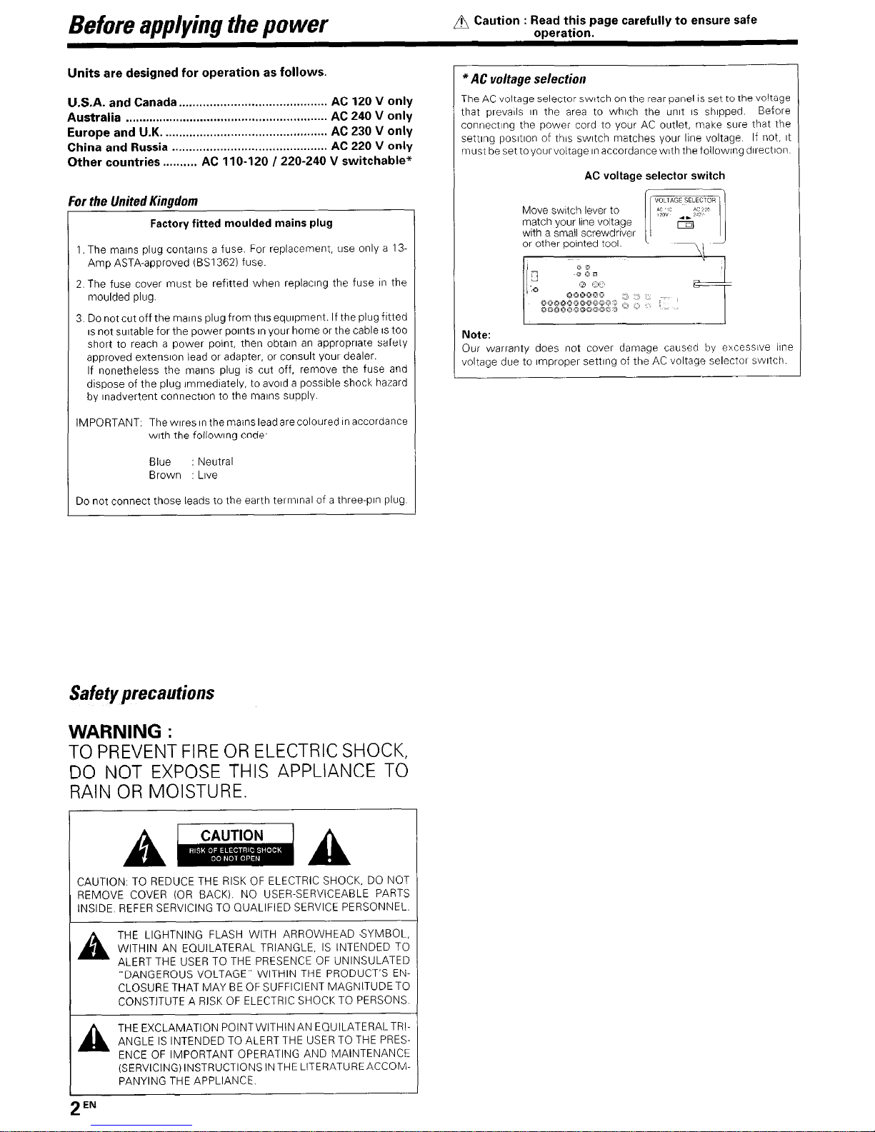
Units are designed for operation as follows.
U.S.A. and Canada.. .........................................
AC 120 V only
Australia
...........................................................
AC 240 V only
Europe and U.K.
...............................................
AC 230 V only
China and Russia
.............................................
AC 220 V only
Other countries ..........
AC 1 IO-120 I 220-240 V switchable”
For the United Kingdom
Factory fitted moulded mains plug
1. The mains plug contains a fuse. For replacement, use only a 13Amp ASTA-approved (BSI 3621 fuse.
2. The fuse cover must be refttted when replacing the fuse II- the
moulded plug.
3 Do not cut off the mains plug from thus equrpment. If the plug fitted
IS not suitable for the power pornts rn your home or the cable IS too
short to reach a power point, then obtatn an appropriate safety
approved extensron lead or adapter, or consult your dealer.
If nonetheless the marns plug IS cut off, remove the fuse and
dispose of the plug immedrately, to avoid a possible shock hazard
by Inadvertent connectron to the marns supply
IMPORTANT. The wares rn the mains lead are coloured rn accordance
wrth the followrng code,
Blue
: Neutral
Brown
Love
Do not connect those leads to the earth terminal of a three-pin plug
Safety precautions
WARNING :
TO PREVENT FIRE OR ELECTRIC SHOCK,
DO NOT EXPOSE THIS APPLIANCE TO
RAIN OR MOISTURE.
CAUTION. TO REDUCE THE RISK OF ELECTRIC SHOCK, DO NOT
REMOVE COVER (OR BACK). NO USER-SERVICEABLE PARTS
INSIDE REFER SERVICING TO QUALIFIED SERVICE PERSONNEL
THE LIGHTNING FLASH WITH ARROWHEAD SYMBOL,
WITHIN AN EQUILATERAL TRIANGLE, IS INTENDED TO
ALERT THE USER TO THE PRESENCE OF UNINSULATED
“DANGEROUS VOLTAGE” WITHIN THE PRODUCT’S EN-
CLOSURE THAT MAY BE OF SUFFICIENT MAGNITUDE TO
CONSTITUTE A RISK OF ELECTRIC SHOCK TO PERSONS
AA
THEEXCLAMATION POINTWITHINAN EQUILATERALTRIANGLE IS INTENDED TO ALERT THE USER TO THE PRES-
ENCE OF IMPORTANT OPERATING AND MAINTENANCE
(SERVICING) INSTRUCTIONS IN THE LITERATUREACCOMPANYING THE APPLIANCE.
*AC voltage selection
The AC voltage selector switch on the rear panel is set to the voltage
that prevarls rn the area to whrch the unit IS shipped
Before
connecting the power cord to your AC outlet, make sure that the
settrng positron of this swatch matches your line voltage
If not, rt
must be set toyourvoltage II- accordancewith the followrng drrectron
AC voltage selector switch
Note:
Our warranty does not cover damage caused by excessive lrne
voltage due to rmproper settrng of the AC voltage selector swatch
2
EN
Before applying the power
Contents
Caution : Read the pages marked A carefully to ensure
safe operation.
Unpacking
3
How to use this manual
4
Special features 5
Names and functions of parts . ...,.................,.. 6
MaIn Unit 6
Remote control unit (RC-R0725) (KRF-V7060D)
and (RC-R0727) (VR-6050/KRF-V6060D). 7
Remote control unrt (RC-R0726) (KRF-V6060D)
(For the U.K. onlv) 8
S.&g up the &stem . . . . . . . . . . . . . . . . . . . . . . . . . . . . . . . . . . , ..,., 9
Connecting audro components
10
Connecting video components. 11
DIgItal connections
12
Connecting a DVD player (S-channel Input).
13
Connecting the speakers.
14
Connecting the terminals
15
Connecting to the AV AUX lacks
16
Connecting the antennas 16
Connecting the system control 17
Preparing the remote control
17
Preparing for surround sound
. . . . . . . . . . . . . . . . . . . . . . . 18
Speaker settings
18
Normal playback . . . . . . . . . . . . . . . . . . . . . . . . . . . . . . . . . . . . . . . . . . . . . . 21
Preparing for playback
21
Listening to a source component 21
AdlustIng the sound.
Recording . . . . . . . . . . . . . . . . . . . . . . . . . . . . . . . . . . . . . . . . . . . . . . . . . . . . . . . . . .
ii
Recording audio (analog sources)
23
Recordrng vrdeo
23
Recording audio (digItal sources)
Listening to radio broadcasts . . . . . . . . . . . . . . :........
ii
Tul?lng (non-RDS) radio stations
24
Using RDS (Radio Data System)
(For the U K only)
24
Presetting radio stations rmanually
24
Recelvlng preset statlons
25
Recelvlng preset statlons II? order (P CALL) 25
Using the RDS DISP iDIsplay) key
(For the U K only)
25
Presetting RDS stations (RDS AUTO MEMORY)
(For the U K onlyi
26
Tuning by Program TYpe (PTY search)
(For the U K only)
Ambience effects . . . . . I....
. . . . . . . . ., ., . . . . . . . . . . . . . . . . . . SY
Surround [modes
27
Surround play
29
DVD G-channel playback
30
Convenient functlons
30
Basic remote control operations for other
components . . . . . . . . . . . . . . . . . . . . . . . . . . . . . . . . . . . . . . . . . . . . . . . . . . . . . . . 33
Reglstenng setup codes for other
coimponents
33
Operating other components
34
Setup code chart
(RC-R07271 WR-6050/KRF-V6060Di
(RC-R0725) (KRF-V7060D)
35
Setup code chart
(RC-R0726) (KRF-V6060D)
(For the U K only)
36
CASSETTE deck, CD player & MD recorder
operations
37
Other romooI?ents’ oDeratIons 38
n
In case of difficulty.. ........................................ 40
Specifications .................................................. 42
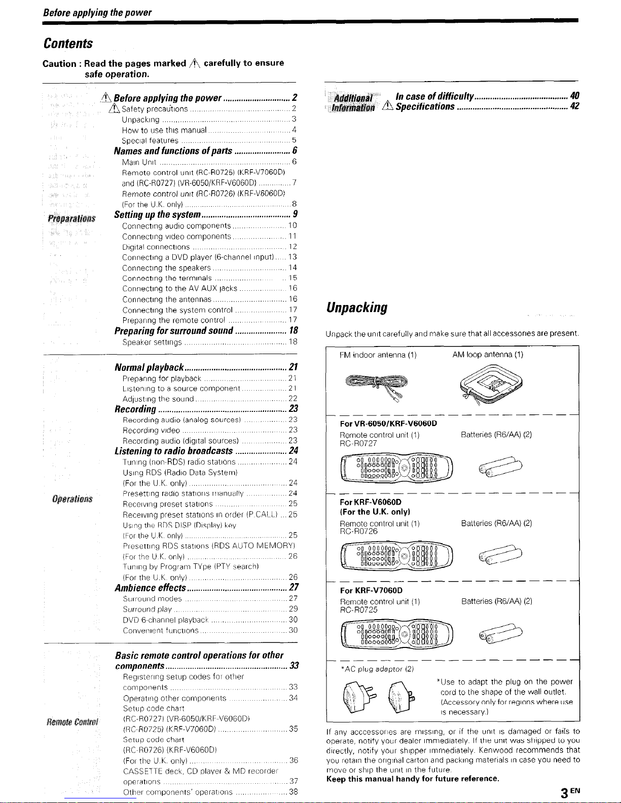
Unpacking
Unpack the unit carefully and make sure that all accessones are present.
FM indoor antenna (1)
AM loop antenna (1)
_------
-------
----
For VR-6050/KRF-V6060D
Remote control untt (I)
Batteries (RG/AA) (2)
RC-R0727
__-----
---------
--
For KRF-V6060D
(For the U.K. onlyl
Remote control unit (1)
Batteries (RG/AA) (2)
RC-R0726
______-------
For KRF-V7060D
Remote control unll (1)
RC-R0725
Batteries (RG/AA) (2)
---------------
*AC plug adaptor (2)
*Use to adapt the plug on the pow<
cord to the shape of the wall outlet.
@ Q ,s”ecessary)
(Accessory only for regions where u:
If any acccessorles are mlsslng, or If the unit IS damaged or fails to
operate, notify your dealer Immediately. If the unrt was shopped to you
directly, notify your shlpper Immediately. Kenwood recommends that
you retaln the origInal carton and packing materials In case you need to
move or ship the unit In rhe future
Keep this manual handy for future reference.
3
EN
Before applying the power
How to use this manual
Thus manual IS drvrded Into four sectrons. Preparatrons, Operatrons,
Remote Control, and Addrtional InformatIon
Preparations
Shows you how to connect your audio and video components to the
recerver and prepare the surround processor
Since thus recerver works wrth all your audro and vrdeo components, we
will guide you rn settrng up your system to be as easy as possrble
Operations
Shows you how to operate the varrous functrons avariable on the
receiver.
Remote Control
Shows you how to operate other components usrng the remote control,
as well as a detailed explanation of all remote control operatrons. Once
you have registered your components wrth the proper setup codes, you’ll
be able to operate both thus recerverand yourotherAVcomponents (TV,
VCR, DVD player, CD player, etc.) usrng the remote control supplied wrth
thus recerver.
Additional Information
Shows you additronal rnformatron such as “In case of difficulty” ftroubleshootrng) and “Specifrcatrons”.
Maintenance of the unit
When the front panel or case becomes drrty, wrpe wrth a soft, dry
cloth. Do not use thrnner, benzene, alcohol, etc. for these agents may
cause drscoloratron.
In regard to contact cleaner
Do not use contact cleaners because It could cause a malfunctron. Be
specrally careful not to use contact cleaners contarnrng 011, for they
may deform the plastrc component
Memory back up function
Please note that the followrng Items wrll be deleted from the unrt’s
memory If the power cord IS drsconnected from the AC outlet for
approxrmately 1 day.
l
Power mode.
l
Distance settrng
l
Input selector settings.
l
Input mode setting.
l
Picture output.
l
Mrdnrght mode settrng.
l
Speaker ON/OFF.
l
PRO LOGIC II mode setting
l
Volume level.
l
CS II mode settrng
l
BASS, TREBLE, INPUT level. l Broadcast band.
. TONE ON/OFF.
l
Frequency settrng
l
LOUDNESS ON/OFF.
l
Preset statrons.
l
Dimmer level.
l
Tunrng mode.
l
MD/TAPE settrngs.
l
DSP mode.
l
Listen mode setting.
l
ACTIVE EQ mode.
l
Speaker settings.
l
SPEAKER EQ mode.
l
SW RE-MIX ON/OFF.
4
EN
br the U.S.A.
FCC WARNRQG
Thrsequrpment maygenerateoruseradrofrequencyenergy Changes
or modrfrcatrons to thus equipment may cause harmful Interference
unless the modrficatrons are expressly approved rn the rnstructron
manual The user could lose the authority to operate this equrpment
If an unauthorized change or modifrcatron IS made.
NOTE:
This equrpment has been tested and found to complywrth the lkmrts for
a Class B drgrtal device, pursuant to Part 15 of the FCC Rules These
lrmrts are desrgned to provide reasonable protectron against harmful
interference rn a resrdentral installatron. This equipment may cause
harmful interference to radio communrcatrons, rf It IS not Installed and
used rn accordance wrth the rnstructrons. However, there IS no guaran-
tee that Interference wrll not occur rn a partrcular rnstallatron If thrs
equipment does cause harmful Interference to radio or televisron
reception, whrch can be determrned by turnrng the equrpment off and
on, the user IS encouraged to try to correct the Interference by one or
more of the followrng measures:
- - Reorient or relocate the recervrng antenna
- - Increase the separation between the equipment and recerver
- - Connect the equrpment Into an outlet on a crrcurt drfferent from
that to whrch the recerver IS connected.
--
Consult the dealeroran experienced radro/TV technrcian for help
For the U.S.A.
This remrnder IS provrded to call the CATVsystem rnstaller’s attentron
to Artrcle 820-40 of the NEC that provrdes guidelines for proper
grounding and, rn partrcular, speciiies that the cable ground shall be
connected to the grounding system of the burldrng. as close to the
point of cable entry as practrcal.
AS
an ENERGY STAR@ Partner, Kenwood Corpora-
tron has determrned that this product meets the
gurdelrnes for energy effrcrency
Thus product can save energy Savrng energy re-
duces arr pollutron and lowers utrlrty brlls.
Before aoolvino the oower
SpeciaQ featurm
True home theater sound
Thrs receiver lrvcorporates a wide varrety of surround modes to brrng you
~max~nium wpyment from your video software Select a surround mode
accordrng to yotrl eqirrprnent or the software you are going to play and
et1p/ -2
Dolby Digital and Dolby Digital EX
The DOLBY DIGITAL mode lets you enjoy full drgrtal surround from
software processed rn the Dolby Drgrtal format Dolby Drgrtal provrdes
up to 5 1 channels of Independent drgltal audio for better sound quality
at?d more fpoweiful presence than conventronal Dolby Surround
As for Dolby Drgrtal EX, It creates SIX full-bandwIdth output channels
from the 5 I cl~annel sources Thus IS done usrng a matrix decoder that
derives tllrec surrournd channels from the two in the orrginal recording
For best tes?ilts, Dolby DIgItal EX should be used wrth movre soundtracks recorded wrth Dolby Drgrtal Surround EX
Dolby PRO LOGIC11
Dolby PRO LOGIC II, whrlst totally compatrble wrth Its predecessor
PBO LOGIC, provrdes greater advantages rn surround sound It allows
the user to enjoy tile conventronal stereo or Dolby Surrout?d wrth a
conv~ncrng “5 1 ilke” presentation PRO LOGIC II offers special featLtlesforcontrollrng the overall spatral, drrnensronalrtyand frontal sound
freid rmagrnc] PRO LOGIC II produces an lrnpressrve surrour?d solrnd
frown vrtieo softwate marked ~~~~OLBVSURRDUNOI and three-drmenslonal
space fton-i rn~us~c CD When Irstenrng to musrc, you WIII be able to enjoy
the experience of stleer STEREO surround souncl
DTS
DTS (Digital Theater System) IS a 5 1 channel drgrtal audio format that
~~rov~desf~vefull-spectrumchannelsat-idor?elow-frequency(si~bwoofei)
chat?nei for rrt?precedented clarrty, optrmum chat?nel separation and a
(wide) dynamc ianye
In the DTS rnode, the 5 1 charvlel drgrtal Input from a DTS CD, LD or
DVD drcc lc~rry~ng the “DTS” markrng) can be played in DIgItal SUIround
llnpoltdr11
When <r DTS rlrsc is played on a CD, LD 01 DVD player, rnorse may be
oiltput from the analog output It is recommended that you connect the
drgltal output of the player to the drgrtal Input of tills unit
Multi channel surround sound
(SRS Circle SurroundU
CO)CS.)
SRS Crcle Surround llTM Improves on Its predecessor CS-5 lTM resultrng in tile CS-6 I’” system, enabling you to lrsterl to realrstrc, rmultrchannel. slrrr oLlnd sound playback from a stereo source or cot1ver>trona/
surround-erxoded video source You already enjoy ltstenrng to Dolby
drgrtal sound/DTS rnultl-channel sound wrtl? your rmultl-speakers Now
you can listen to audio CDs, MDs, Broadcast and Home Theater usrng
your mrultvsf~eakers YOLI will dIscover a new type of sound throng11
SRS Cricle Surrout7c II
DSP surround modes
The DSP (Drgrtal Srgnal Processor) used for thus recerver incorporates
a variety of high qualtty adjustable sound fields, llke “ARENA”, “JAZZ
CLUB”,
“THEATER”, “STADIUM” and “DISCO” It rscompatrble wrth
almost any krnd of program source.
DVD Bchannel input
If you own a DVD player equipped wrth 6-channel output, this receiver
allows you to obtain the full surround sound Impact of DVD source
material featuring multi-channel encoding Since the source stgnals are
digItal and each channel IS Input Independently. the resulting ambrence
IS far superror to what can be achreved wrth conventronal surround
sound systems
ACTIVE EQ
ACTIVE EQ mode wrll produce a more clynamrc sound quairty In any
conditron You can enjoy a more rmpressrve sound effect when ACTIVE
EQ IS turned on during Dolby Drgrtal and DTS playback
SPEAKER EQ
TheSPEAKER EQfunct~onw~llautomat~callydetectthevar~ousfeatures
of each speaker and effectively creates a stereoscoprc sound effect.
Universal It3 IInfraRed) remote control
In addition to the basic receiver, the remote control supplred wrth thus
receiver can also operate almost all of your remote controllable audio
and video components Just follow the sample setup procedure to
register the components you have connected
RDS (Radio Data System) tuner (For the UK. only)
The receiver IS equrpped wrth an RDS tuner that provrdes several
convenrent tunrng functrons RDS Auto Memory, to automatrcally
preset up to 40 RDS statrons broadcasttng different programs; station
name display, to show you the name of the current broadcast station;
and PTY search to let you tune stations by program type
PTY (Program Type) search (For the U.K. only)
Tune the statrons by specrfyrng the type of program you want to hear.
5
EN
Names and functions of parts
Main unit
Speaker MUTE CLIP Input mode Listen mode
indrcators Indicator rndrcator indicators rndicators
RDS indicators
AUTO indrcator
MEMORY indicator
STEREO rndrcator
Speaker selection indicators
Input channel indicators
Output channel indrcators
Display
Frequency display
Input display
Preset channel display
Surround mode display
ForVR-6050
For KRF-V7060D and
KRF-V6060D (For the U.K. only)
0 POWER ON/OFF key
(For KRF-V7060D/V6060D)
-&
Use to turn the main power ON/OFF
0 ON/STANDBY 0 key
(For KRF-V7060D/V6060D) -2L
Use to turn the power ON/STANDBY when
the POWER IS turned ON
STANDBY indicator
0 POWER ON/STANDBY ti key
(For VR-6050)
-de
Use to turn the power ON/STANDBY
STANDBY indicator
@ A SPEAKERS B keys -&?,
Use to turn the A/B speakers ON/OFF.
0 LOUDNESS key
-22
Use to swatch the status of LOUDNESS
0 SPEAKER EQ key -122
Use to select SPEAKER EQ’s setting.
0 Surround indicators
DSP indicator
-&
Lrghts when the receiver IS in the DSP mode.
SPEAKER EQ indicator
-D@L
Lrghts when the recerver IS rn the SPEAKER
EQ mode.
ACTIVE EQ indicator
-,-Gf
Lrghts when the receiver IS rn the ACTIVE EQ
mode.
DOLBY DIGITAL indicator
-L&
Lights when the recerver IS rn the Dolby
Digrtal mode.
Standby mode
DTS indicator
-2%
Lrghts when the recerver IS In tlhe DTS mode.
CS 5 indicator
-2%
Lights when the recerver IS II, tile CIRCLE
SURROUND II mode
0 ACTIVE ECI key
-22
Use to select ACTIVE EQ’s setting.
0 DSP key
-2%
Use to select any of the DSP mode
0 STEREO key
-2%
Use to swatch the listen mode to STEREO
@ INPUT MODE key - -Q-l
Use to swatch between the full auto, dIgital
and analog Inputs
@ DIMMER key
Use to select the REC MODE
- 23
Use to adjust the brrghtness of the drsplay
-X
@ VOLUME CONTROL knob
- 21.
@ MUTE key
-
??.
Use to temporarrly mute the sound
8 PHONES jack
- 22.
Use for headphone lrstenrng
@ Input Selector keys
- 21
DVD/GCH,CD/DVD,AUXfforVR-6050/KRFV6060D) or PHONO Ifor KRF-V7060D and
KRF-V6060D (for the U.K. onlyll, TUNER,
VIDEO 1, VIDEO 2, VIDEO 3, MD/TAPE
Use to select Input sources
@ SOUND key
-2%
Use to adjust the sound quality and the ambrence effects
0 BAND key
- 24
Use to select the broadcast band
0 AUTO key
- 24
Use to select the auto or manila1 tunrng
mode.
@ TONE key
-2;
Use to switch the stators of TONE control
@I MEMORY key
-25-26
Use to store radio stations 117 the preset
memory and to start the Auto Memory (for
the U.K only)
0 SETUP key
- !?.
Use to select the speakers’ settlngs etc
@ A/V keys
-118
Usefor selectronad~ustmentsdurrng SOUND,
SETUP and PRESET CHANNEL functrons
@ MULTI CONTROL knob
- !QUse to control a varrety of settrngs
@ LISTEN MODE knob
-8 2%
Use to select the Ilstenrng rmode
0 zkUX (S VIDEO, VIDEO, AUDIO L/R)
- 16_
@ AV AUX key
- !6
Use to switch the rt?put to AV AUX
While the standby rndrcator IS lit, a small amount of power IS supplIed
to the system to back up the memory. This IS called standby mode
Under the condrtron, the system can be turned ON by remote control
unrt.
The power II? thus eqLirpment wrll not be completely ctrt off frown the AC
wall outlet wher? the main swatch IS turned OFF
gEN
Names and functions of
parts
Remote control unit (RC-RO725) (KRF-V706OD) and (RC-R0727) (VR-605O/KRF-V606OD)
This remote control unit can be use not only for Kenwood products but also for other non-Kenwood products by setting the appropnate manufacturer’s
setuo codes.
-m
PHONO
-
REMOTE MODE keys (DVD, CBL, DSSI
SAT, VCR, TV, OTHERS)
-22
Use to select the components reglstered at
the respective Input
Numeric keys
-&X
Provide functions ldentlcal to those of the
orIgInal relnote control supplied with the
com-
ponent you are controlling
INPUT MODE key
-&
Use to switch between the full auto, dIgItal
and analog Inputs
STEREO key
-A
Use to switch the Itsten mode to STEREO
CH +/- keys
Use to select the channels
))I DVD 144 keys
When In DVD player operations, these keys
functlon as skip keys
TV CONTROL keys
Use when In TV operatlol?
TOP MENU key
Use to operate the DVD component
SET UP key
-&
IJse to select the speakers’ settings etc
0 Joystick
ENTER
Use to operate other components
MULTI CONTROL A/r
-A
Use to control a variety of settings
Use to operate other components
P.CALL 144 /DOWN 4 and P.CALL/UP ttl
.
-&
Usefol selectlonad~ustmentsdunngSOUND,
SET UP and PRESET channel functions
@ TUNING
44/b,
keys
-EC
Use to operate the tuner mode
If CD, MD or TAPE IS selected as the Input
source, these keys function as search keys
@ DISC SKIP key
Use to operate other components.
If CD IS selected as the Input source. this key
functions as the multi-CD player disc skip
kev
INPUT SEL key
A/B key
If TAPE 1s selected as the Input source, this IS
A and B deck of a double cassette deck.
0 DISC SEL key
Use to operate other components
8 INPUT SELECTOR keys [DVDIGCH, CD/
DVD, AUX or PHONO (for RC-I30725 only).
TUNER, VIDEO 1, VIDEO 2, VIDEO 3, MD/
TAPE, AV AUXI
Use to select the Input sources.
-E
@ LOUDNESS key -E
Use to switch the status of LOUDNESS
Q1 SOURCE (0 I key
Use to turn the other components ON/OFF
0 POWER (0 1 key
-L&
Use to turn the receiver ON/OFF
0 RECEIVER key
Use to return to the operation of the receiver.
0 LISTEN MODE n/o keys
-E
Use to select the llstenlng mode
@ ACTIVE ECI key -22
Use to select ACTIVE EQ’s setting
@ SPEAKER EQ key
-&
Use to select SPEAKER EQ’s setting.
@ DSP MODE key
-*&
Use to select any of the DSP MODE
@ MUTE key -22
Q PAGE n/o keys
Use to operate the DVD component
0 OSD key
Use to operate the DVD component Use to temporarrly mute the sound
the receiver and on the remote control,
the name of the remote control key m
this manual is indicated in parentheses.
@ VOLUME +I- keys
-a
Use to adjust the receiver volume.
Q, MENU key
Use to operate other components.
SOUND key
-Eg
Use to adjust the sound quality and the amblence effects
@ RETURN key
Use to operate other components
@ 4 key
Use to operate other components.
FLIP key
Use to operate other components.
@ b/II key
If CD IS selected as the Input source, this key
functions as the play/pause key.
If MDorTAPE keylsselectedaslnputsource,
this key functions as the play key.
BAND key
-a
Use to select the broadcast band.
@ n
key
If CD, MD, or TAPE IS selected as the Input
source, this key functions as the stop key.
AUTO key
-a
Use to select the auto or manual tuning
mode.
@J DIMMER key
-@2I
Use io adjust the brightness of the display.
II key
Use to operate other components
@I BASS BOOST key
-lx
Use to select the maximum adjustment setting for the low frequency range
@ TONE key
422
Use to switch the status of TONE control.
7
EN
Names and functions of parts
Remote control unit (RC40726) (KRF- v606OD) (For the U.K.
OIII~)
This remote control unit can be used not only for Kenwood products but also for other non-Kenwood products by settrnq the appropriate manufacturer’s
setup codes
0 REMOTE MODE keys (DVD, CD, CBLISAT,
VCR, TV, OTHERS1
-.s
Use to select the components reglstered at
the respective Input
Q Numeric keys
-33
Provrde functrons rdentrcal to those of the
origrnal remote control supplredwrth the component you are controllrng.
0 INPUT MODE key
Use to swatch between the full auto, drgrtal
and analog Inputs
0 STEREO key
--Use to swatch the lrsten mode to STEREO
0 CH +I- keys
Use to select the channels
,H DVD 1~ keys
When rn DVD player operatrons, these keys
functron as skrp keys.
0 TV CONTROL keys
Use when rn TV operatron.
0 TOP MENU key
Use to operate the DVD component
SET UP key
-LX
Use to select the speakers’ settings etc
0 $s;;k
Use to operate other components.
MULTI CONTROL A/r
- lx
Use to control a variety of settings
Use to operate other components.
P.CALL w /DOWN 4 and P.CALL/UP +bl
b
--a
Useforselectronadfustmentsdurrng SOUND,
SET UP and PRESET channel functrons
0 RDS DISP key -425
Use for RDS function.
PAGE DOWN key
Use to operate the DVD component
PTY key
-25
Use for PTY search
PAGE UP key
Use to operate the DVD component
0 OSD key
Use to operate the DVD component
@ TUNING 44/t) keys
- 24
Use to operate the tuner mode
If CD, MD or TAPE IS selected as the Input
source, these keys function as search keys
0 DISC SKIP key
If CD IS selected as the Input source, this key
functrons as the mtlltl-CD player drsc skip
kev
A/B key
If TAPE IS selected as the Input source, this IS
A and B deck of a double cassette deck
8 DISC SEL key
Use to operate other components
INPUT SEL key
Use to operate other components
@ INPUT SEL. keys IDVD/GCH, CD/DVD,
PHONO, TUNER, VIDEO 1, VIDEO 2,
VJDEO 3, MD/TAPE, AV AUXI
Use to select the Input sources -a
@ LOUDNESS key
-22
Use to switch the status of LOUDNESS.
@ SOURCE I (!I ) key
Use to turn the other components ON/OFF
0 POWER (0 I key
Use to turn the receiver ON/OFF
0 RECEIVER key
Use to return to the operation of the receiver
0 LISTEN MODE A/V keys
-gi
Use to select the lrstenrng mode
@ ACTIVE EQ key
--9&
Use to select ACTIVE EQ’s setting
@ SPEAKER EQ key
-2’
Use to select SPEAKER EQ’s setting
@ DSP MODE key
- _2
Use to select any of the DSP MODE
If the name of a function is different on
the receiver and on the remote control,
the name of the remote control key in
this manual is indicated in parentheses.
@ MUTE key
- L&
Use to temporarrly mute the sound
@ VOLUME +I- keys
-;?‘.
Use to adjust the recerver volume
@ MENU key
Use to operate other components
SOUND key
- 20
Use to adjust the sound quailty and the ambrence effects
@ RETURN key
Use to operate other components
@ 4 key
Use to operate other components
FLIP key
Use to operate other components
@ F/II key
If CD IS selected as the Input source, thus key
functrons as the play/pause key
If MDorTAPEkey~sselectedasrnputsource,
thus key functrons as the play key
BAND key - -?4;.
Use to select the broadcast band
@ n
key
If CD, MD, or TAPE IS selected as the Input
source, this key functions as the stop key
AUTO key
-_2E
Use to select the ailto or Imanual tuning
mode
@ DIMMER key
-3’
Use to adjust tlhe brrghtness of the drsplay
II key
Use to operate other components
@ BASS BOOST key
-21
Use to select the maxrmum adfustment setting for the low freqllency range.
@ TONE key
-22_
Use to switch the status of TONE control
8EN
Seffing up fhe sysfem
Make connections as shown in the following pages.
When connecting the related system components, be sure
to refer to the instruction manuals supplied with the compo-
nents you are connecting.
Do
not connect the power cord to a wall outlet until all
connections are completed.
Notes
1 Be sure to ltisert all connectIon cords securely if their connections are
Imperfect, socrrnd n?ay not be produced or there WIII be no/se inference
2 Be sure to remove the power cord from the AC outlet before plugging
or unplugging any connectIon cords Plugginglunplugglng connection
cords without dlsconnectlng the power cord can cause malfunctions
and (may darnage the unit
3 Do not connect power cords from components whose power con-
sumptlon 1s larger than what IS indicated on the AC outlet at the rear
of this unit
Analog connections
Audio connectIons are tmade using RCA pin cords These cables transfer
stereo audio siglnal in an “analog” form. This means the audio slgnal
corresponds to the actual audio of two channels These cables usually
have 2 plugs on each end, one red for the right channel and one white for
the left channel. These cables are usually packed together with the
source tInIt, or are available at your local electronics retailer
though all connections Ihave been made properly, reset tiie microcomputel ieferrlng to “In case of difficulty”
CAUTIO~II
Be sure to adhere to the following, or proper ventilation will be
blocked causing damage or fire hazard.
l
Do not place any objects Impairing heat radlatlon onto the top of the
unit
l
Leave solve space around the unit (from rhe largest outsIde
dlmenslon lncludll?g plolectlon) equal to or greater than, shown
below
Top panel : 50 cm Side panel : 10 cm Back panel : 10 cm
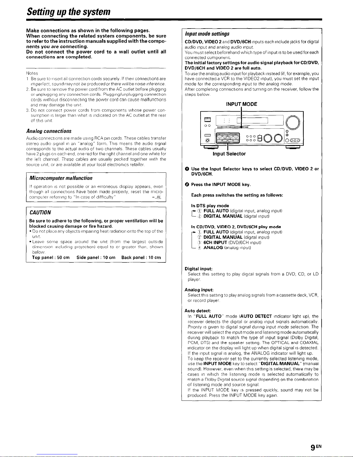
Input mode settings
CD/DVD, VIDEO 2 and DVD/GCH Inputs each Include jacks for dIgItal
audio Input and analog audio Input.
You must select beforehand which type of Input IS to be used for each
connected component.
The initial factory settings for audio signal playback for CWDVD.
DVD/GCH and VIDEO 2 are full auto.
To use the analog audio Input for playback Instead (If, for example, you
have connected a VCR to the VIDEO2 Input), you must set the Input
mode for the corresponding Input to the analog mode.
After completing connections and turning on the receiver, follow the
steps below.
INPUT,MODE
Input Selector
0 Use the Input Selector keys to select CD/DVD, VIDEO 2 or
DVDIGCH.
0 Press the INPUT MODE key.
Each press switches the setting as follows:
In DTS play mode
f7 FULL AUTO (digItal Input, analog Input)
r--
z DIGITAL MANUAL (dlgltal Input1
In CD/DVD, VIDEO 2, DVD/GCH play mode
3, FULL AUTO (dIgItal Input, analog Input)
T DIGITAL MANUAL (digital Input)
3 6CH INPUT (DVD/GCH Input)
3 ANALOG (analog input)
Digital input:
Select this setllng to play digital signals from a DVD, CD, or LD
player
Analog input:
Select this setting to play analog signals from a cassette deck, VCR,
or record player
Auto detect:
In “FULL AUTO” mode (AUTO DETECT lndlcator light up). the
receiver detects the dIgItal or analog Input signals automatically.
Pnonty IS given to dIgItal slgnal during Input mode selectton. The
receiver WIII select the Input mode and llstenlng mode automatlcally
during playback to match the type of Input slgnal (Dolby DIgItal.
PCM, DTS) and the speaker setting. The OPTICAL and COAXIAL
Indicator on the display will light up when digltal signal IS detected.
If the Input slgnal IS analog, the ANALOG Indicator WIII light up.
To keep the receiver set to the currently selected listening mode,
use the INPUT MODE key to select “DIGITAL MANUAL” (manual
sound) However, even when this setting IS selected, there may be
cases I” which the listening mode IS selected automatically to
match a Dolby DIgItal source slgnal depending on the comblnatlon
of listening mode and source slgnal
If the INPUT MODE key IS pressed quickly, sound may not be
produced. Press the INPUT MODE key agaIn
gEN
Settino UD the svstem
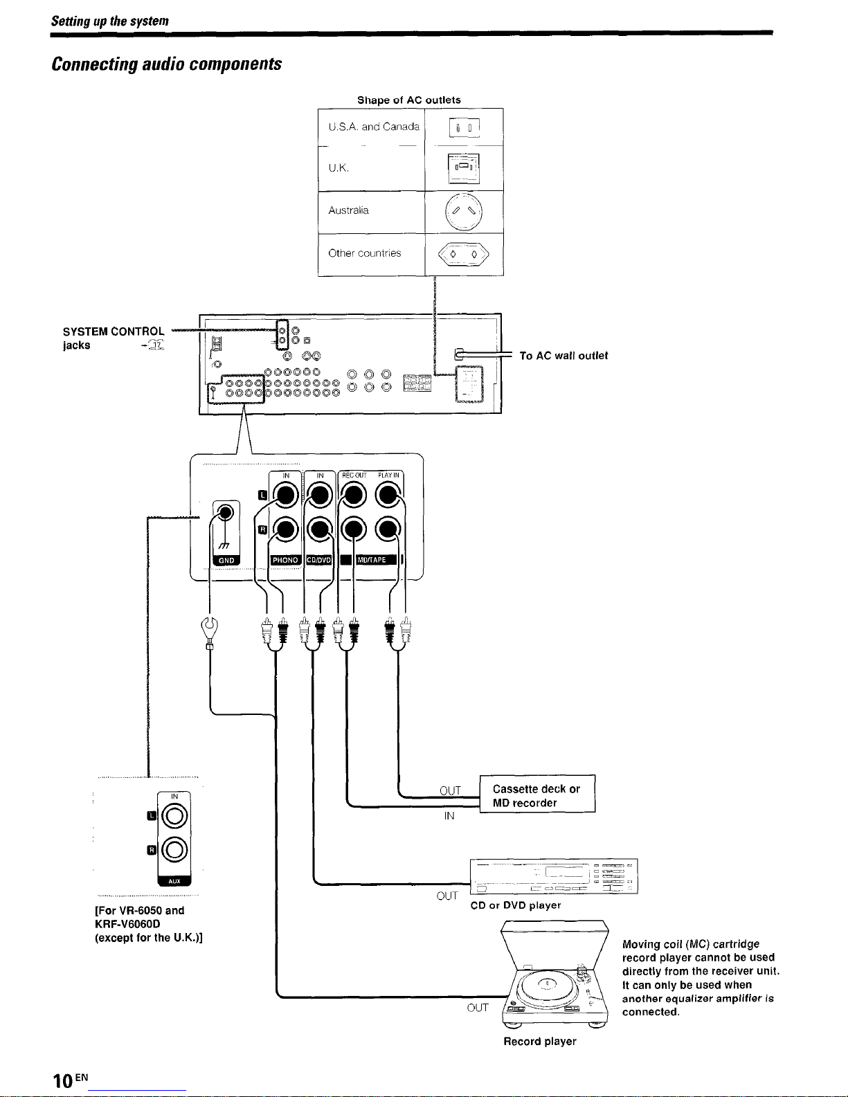
Connecting audio components
Shaoe of AC outlets
SYSTEM CONTROL
jacks -‘ii-
U.S.A. and Canada
IFI
Australia
1 Othercountrles / ,a /
[For W-6050 and
KRF-V6060D
(except for the U.K.)]
To AC wall outlet
_Ll,ZE
I
CD or DVD player
Moving coil (MC) cartridge
record player cannot be used
directly from the receiver unit.
It can only be used when
another equalizer amplifier is
connected.
Record player
lOEN
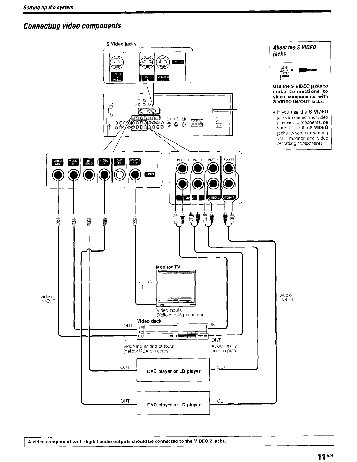
Connecting
video
components
S Video jacks
Video
IN/OUT
Use the S VIDEO jacks to
make connections to
video components with
S VIDEO IN/OUT jacks.
. If you use the S VIDEO
lackstoconnectyourvldeo
playback components, be
we to use the S VIDEO
lacks when connecting
your monitor and video
recording components.
Video deck
/‘-
IN
Monitor TV
Video Inputs
(Yellow RCA pin cords)
Video Inputs and outputs
Audio Inputs
(Yellow RCA pin cords)
and outputs
I
OUT
OUT
. DVD player or LD player
OUT
DVD player or LD player
OUT
Audio
IN/OUT
A video component with digital audio outputs should be connected to the VIDEO 2 jacks.
11 EN
Setting up the system
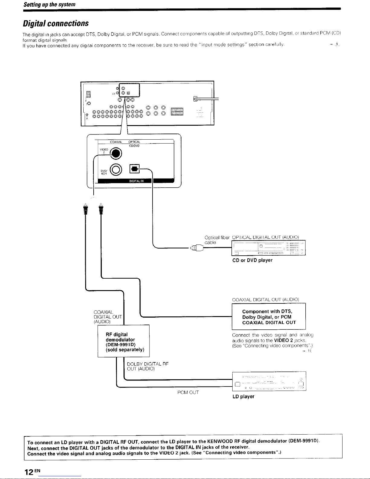
Digital connections
The dIgItal in jacks can accept DTS, Dolby Dtgltal, or PCM signals. Connect components capable of outputtlng DTS, Dolby DIgItal, 01 standard PCM (CD)
format dIgItal signals
If you have connected any digital components to the receiver, be sure to read the
“Input mode settings” sectIon careftllly
- P
CD or DVD player
RF digital
Connect the video slgnal and analog
demodulator
(DEM-9991 D)
audio signals to the VIDEO 2
Jacks.
(sold separately)
(See “Connecting video components”.)
- I/
DOLBY DIGITAL RF
OUT (AUDIO)
To connect an LD player with a DIGITAL RF OUT, connect the LD player to the KENWOOD RF digital demodulator (DEM-9991Dl.
Next, connect the DIGITAL OUT jacks of the demodulator to the DIGITAL IN jacks of the receiver.
Connect the video signal and analog audio signals to the VIDEO 2 jack. (See “Connecting video components”.)
12EN
Setting up the system
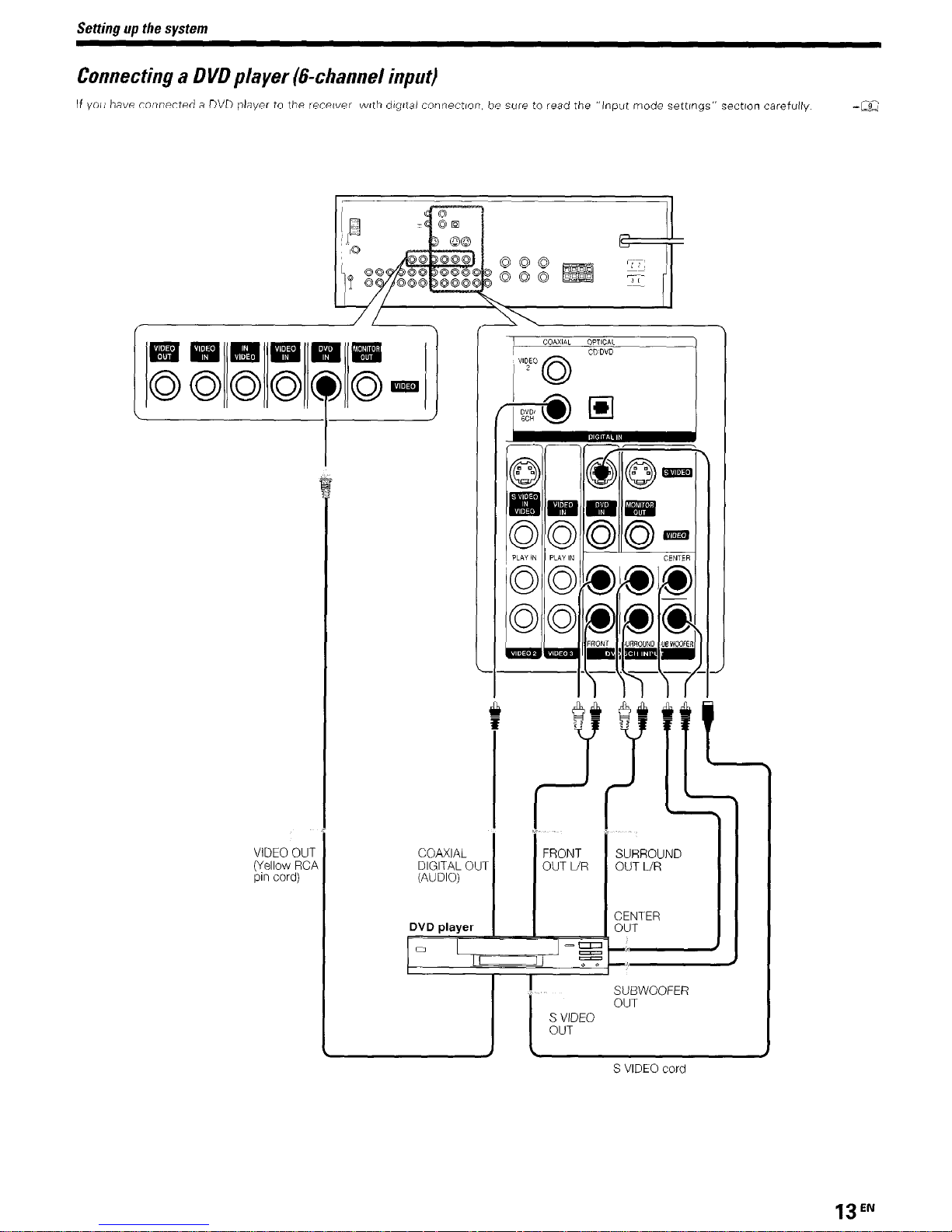
Connecting a DVD player (&channel input)
If you have connected a DVD player to the recewer vwth dlgttal connection, be sure to read the “Input mode settmgs” section carefully
-a
VIDEO OUT
(Yellow RCI
pin cord)
FRONT
OUT LIR
COAXIAL
DIGITAL OUT
(AUDIO)
L
DVD player
0
--II
=
r(
SUBWOOFER
OUT
I
S VIDEO cord
SURROUND
OUT UR
CENTER
13EN
Setting up the system
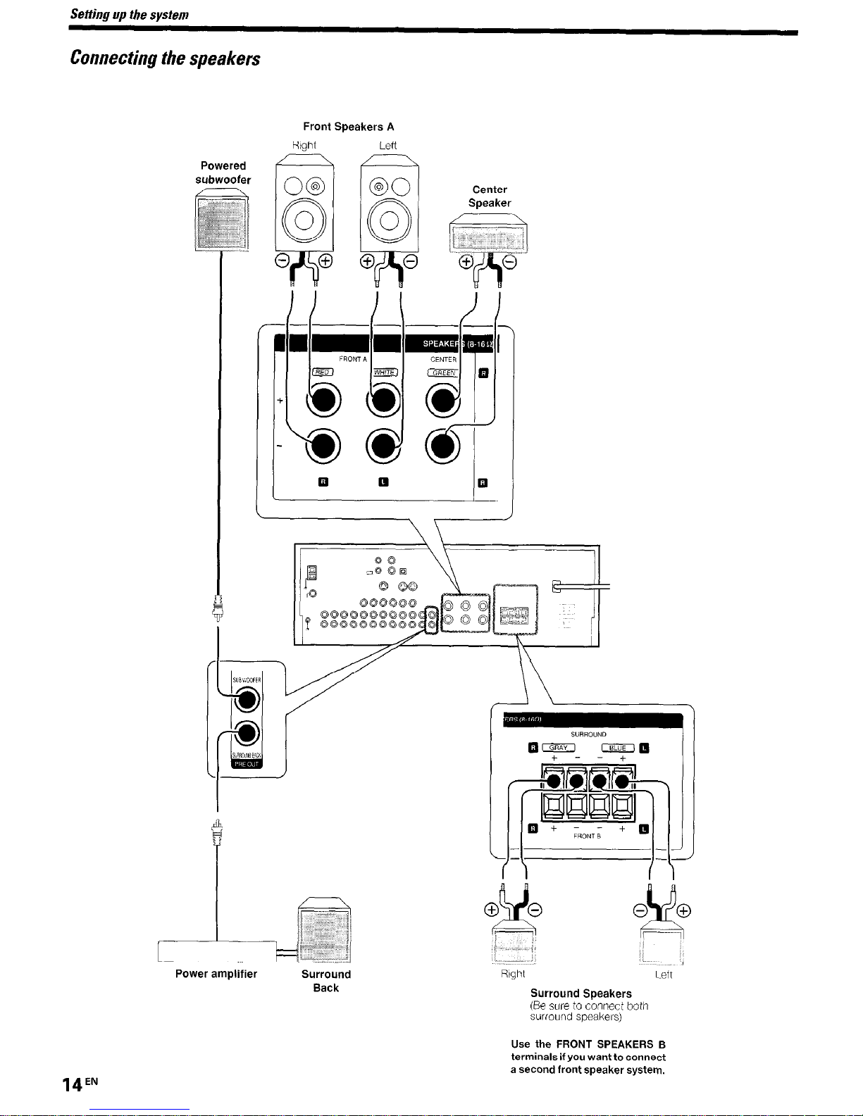
Connecting the speakers
Powered
Front Speakers A
Right
O@
Y
0
0
0 0
Left
@O
ri
0
0
0 0
Center
Speaker
Surround Speakers
(Be sure to connect both
surround speakers)
Use the FRONT SPEAKERS I3
terminals if you want to connect
a second front speaker system.
14EN
Setting up the system
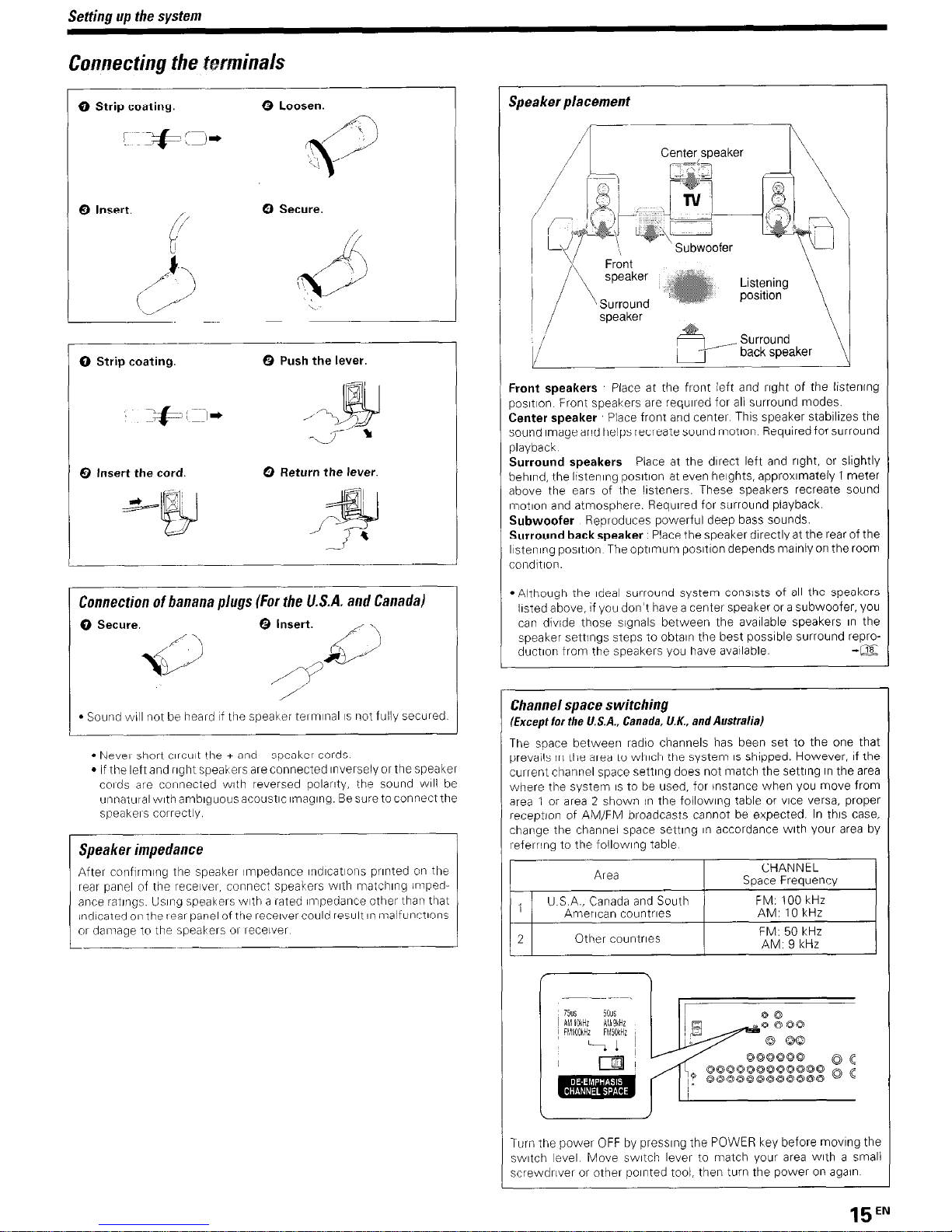
Comecting the tmninals
0 Strip coating.
0 Loosen.
- I
Q Insert. ,,
0 Secure.
r
0 Strip coating.
0 Push the lever.
0 Insert the cord.
0 Return the lever.
Connection
of banana plugs (For the U.S.A. and Canada)
0 Secure.
0 Insert.
y$
55
-\
/PC ’
/’
l
Soutrd will tnot be heard If tire speaker terminal IS not fully secured
l
New short crrcut the + at?d - speaker cords
l
If the left and rrght speakers are connected Inversely or the speaker
cords are connected with reversed polarrty, the sound wrll be
unt?atiltalwlthamblguousacoustlc~~nag~ng Besuretoconnectthe
speakers correctly
Speakerimpedance
After confirming the speaker Impedance rndrcat~ons printed on the
rear panel of the receiver, connect speakers wrth matchrng Impedance iatrngs. Usrng speakers with a rated impedance other than that
Indicated 01, the rear panel of the receiver could result rn malfunctrons
or damage to the speakers 01 receiver
Speaker placement
Center srxaker
\
Front speakers Place at the front left and right of the lrstenrng
posItIon Front speakers are required for all surround modes.
Center speaker Place front and center Thus speaker stabrlrzes the
sound Image and helps recreate sound motion Required for surround
playback
Surround speakers
Place at the direct left and right, or slrghtly
behind, the listenrng posrtron at even heights, approxrmately 1 meter
above the ears of the listeners These speakers recreate sound
tnotron and atmosphere. Required for surround playback.
Subwoofer Reproduces powerful deep bass sounds.
Surround backspeaker
Place the speaker directly at the rear of the
Ilstenrng posrtion The optrmum posrtron depends mainly on the room
cor?ditron
l
Although the Ideal surround system consrsts of all the speakers
lrsted above, if you don’t have a center speaker or a subwoofer. you
can drvide those signals between the available speakers rn the
speaker settngs steps to obtain the best possrble surround reproductron from the speakers you have available
-@z
Channel space switching
Except for the U.S.A., Canada, U.K., and Australia)
The space between radro channels has been set to the one that
prevails in the area to whrch the system IS shopped. However, If the
current channel space settrng does not match the settrng tn the area
where the system IS to be used, for instance when you move from
area 1 or area 2 shown in the followrng table or vrce versa, proper
reception of AM/FM broadcasts cannot be expected. In thus case,
change the channel space setting rn accordance with your area by
referring to the followrng table
Turn the power OFF by presstng the POWER key before movrng the
switch level Move swatch lever to match your area wrth a small
screwdrlver or other pornted tool, then turn the power on again
15EN
 Loading...