

Kenwood KRF-8010-DW, KRFV-8010-DW Service manual
AV SURROUND RECEIVER
A
SPEAKERS
B
BASS BOOST
MONITOR
SOURCE
DIRECT
MULTI CONTROL INPUT SELECTOR
VOLUME CONTROL
DOWN
UP
STANDBY
AV SURROUND RECEIVER
ON / STANDBY
PHONES
- ON – OFF
POWER
PTY
TA/NEWS DISPLAY
BAND
AUTO
MEMORY
INPUT MODE LISTEN MODE
SOUND
SETUP
DOLBY DIGITAL
DVD 6ch INPUT
CLIP INDICATER
CENTER SPEAKERFRONT SPEAKERS
FM
75Ω
GND
AM
ANTENNA
ƒ
SYSTEM CONTROL
REC OUT
PHONO
DVD 6CH. INPUT
CD MD / TAPE
VIDEO 1VIDEO 1
VIDEO 2 VIDEO 3
VIDEO 1
VIDEO 2
DVD 6CH.
VIDEO 3
DVD 6CH.
VIDEO 2
DOLBY DIGITAL / PCM IN
VIDEO 3
SUBWOOFER
SUBWOOFER
SURROUND
SURROUND
SURROUND SPEAKERS
FRONT SPEAKERS
PRE OUTMONITOR
PLAY IN REC OUT PLAY IN REC OUT PLAY IN PLAY IN PLAY IN CENTER
CENTER
SL16
XS8
L
R
+
++
+
----
+
+
--
RAL C
L
L
R
L
R
R
L
R
B
MONITOR
VIDEO IN
VIDEO OUT
KRF-V8010D/V8010DW
SERVICE MANUAL
(E,T,Q,X type)
© 1998-8/B51-5464-00 (K/K) 1751
This manual is available for repair in the Europe, England, Australia and Russia markets.
Please refer to the original manual (B51-5419-00) if need the information in the USA and Canada
and other markets.
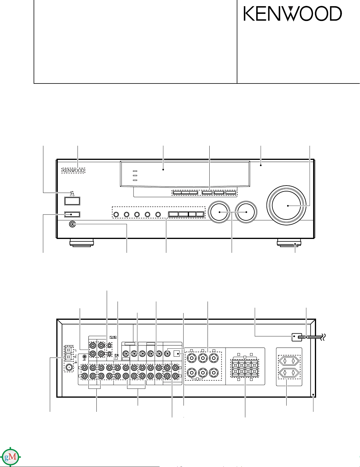
Indicator
(B12-0341-04)
KENWOOD badge
(B43-0302-04)
Front glass
(B10-3428-12)
Knob
(K29-7311-03)
Panel *
(A60-)
Knob
(K29-7312-04)
Knob
(K27-2275-04)
Phono jack
(E63-0114-05)
Lock terminal board
(E20-0321-05)
Phone jack(3P)
(E11-0127-05)
Miniature phone jack(2P)
(E11-0188-05)
Slide switch
(S62-0034-05)
Phono jack
(E63-0094-05)
Phono jack x 2
(E63-0046-15)
Phono jack x 2
(E63-0047-15)
Knob *
(K29-7371-02)
Phono jack
(E63-0093-05)
Phono jack
(E63-0199-05)
Phono jack
(E63-0114-05)
Screw terminal board
(E70-0100-05)
Optical receiving module
(W02-1181-05)
Knob
(K29-7313-04)
Power cord bushing
(J42-0083-05)
Lock terminal board
(E70-0047-05)
AC outlet *
(E03-)
Foot x4
(J02-1168-03)
AC power cord *
(E30-)
Metallic cabinet *
(A01-)
* Refer to parts list on page 31 .
Resetting the Microcomputer
If the microcomputer may malfunction (unit cannot be operated,
or shows an erroneous display) if the power cord is unplugged
while the power is ON, or due to some other external factor. If this
happens, execute the following procedure to reset the microcomputer and return the unit to its normal operating condition.
Please note that resetting the microcomputer will clear the contents
of the memory and returns the unit to the state it was in when it left the
factory.
With the power cord plugged in, turn the POWER key
OFF. Then, while holding down the ON/STANDBY key,
press POWER.
•
FM
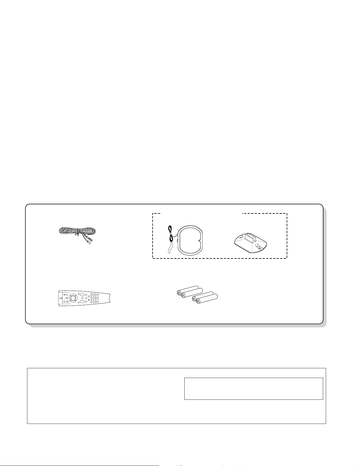
(T90-0836-05)
(A70-1252-05)
Battery cover (A09-0366-08)
indoor antenna (1)
Loop antenna stand (1)
Remote control unit (1)
Batteries (R03/AAA) (4)
AM loop antenna (1) (T90-0833-05)
KRF-V8010D/V8010DW
CONTENTS / ACCESSORIES / CAUTIONS
Contents
CONTENTS / ACCESSORIES / CAUTIONS.............2
CONTROLS...............................................................3
DISASSEMBLY FOR REPAIR...................................5
BLOCK DIAGRAM.....................................................6
CIRCUIT DESCRIPTION...........................................7
ADJUSTMENT........................................................ 10
Please refer to KRF-V5010 (B51-5425-00) and KRF-V7510D (B51-5419-00) service manuals if
need the information on circuit description.
PARTS DESCRIPTIONS.........................................11
PC BOARD ..............................................................12
SCHEMATIC DIAGRAM..........................................17
EXPLODED VIEW ...................................................30
PARTS LIST.............................................................31
SPECIFICATIONS...................................................40
Accessories
Cautions
2
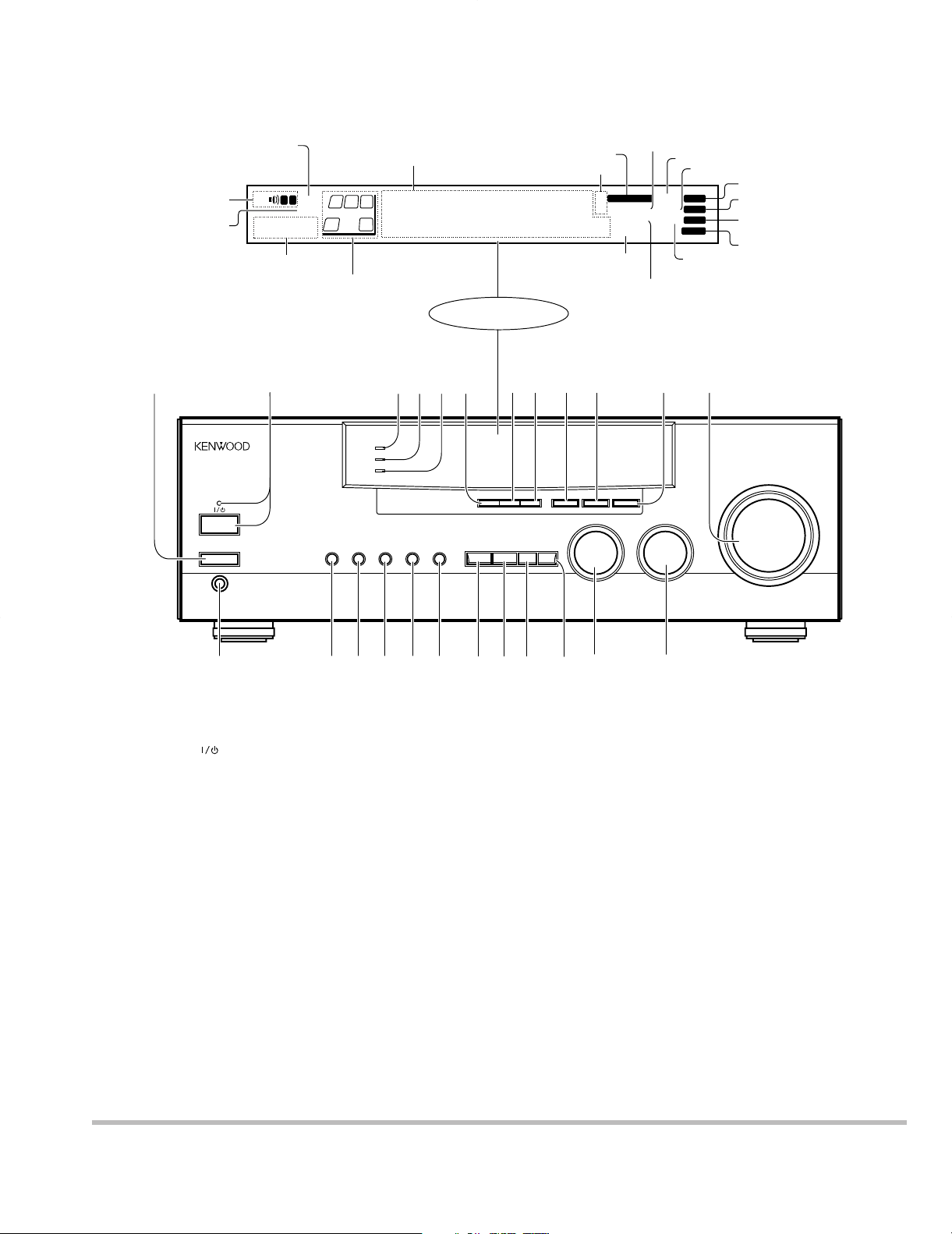
Display
Speaker selection indicators
Output channel indicators
Band indicators
AUTO indicator
MEMO. indicator
ST. indicator
TUNED indicator
3 STEREO indicator
STEREO indicator
About the STANDBY indicator
This unit has a STANDBY indicator. When the STANDBY indicator is lit, the unit consumes a small amount of power to preserve the memory. This is called
STANDBY mode. This mode also lets you turn the power ON using the remote control.
Frequency display,
Input display,
Preset channel display,
Surround mode display
Speaker indicator
MUTE indicator
PRO LOGIC
indicator
S.DIRECT indicator
MONITOR indicator
RDS indicator
TI.VOL indicator
^ BASS BOOST key
Use to select the maximum adjustment
setting for the low frequency range.
& MONITOR key
* SOURCE DIRECT key
( INPUT MODE key
Use to switch between the digital and
analog inputs.
) LISTEN MODE key
Use to select the listening mode.
¡ SOUND key
Use to adjust the sound quality and ambience effects.
™ SETUP key
Use to select the surround sound settings.
£ MULTI CONTROL knob
Used to make a variety of settings.
¢ INPUT SELECTOR knob
Use to select the input sources.
1 POWER key
Use to turn the main power ON/OFF.
2 ON/STANDBY (
) key
Use to switch the power ON/STANDBY
when the POWER is turned ON.
STANDBY indicator
3 DOLBY DIGITAL indicator
Lights when the receiver is in the Dolby
Digital mode.
4 DVD 6ch INPUT indicator
Lights when the receiver is in the DVD 6ch
INPUT mode.
5 CLIP INDICATOR indicator
Lights when the input signal is too large to
be handled by the receiver, and "clipping"
is occurring.
6 PTY key
Use to perform PTY search.
7 TA/NEWS key
8 DISPLAY key
Use to change the display indications when
receiving RDS broadcasts.
9 BAND key
Use to select the broadcast band.
0 AUTO key
Use to select the auto tuning mode
! MEMORY key
Use to store radio stations in the preset
memory.
@ VOLUME CONTROL knob
# PHONES jack
Use for headphone listening.
$ SPEAKERS A key
Use to turn speaker system A on and off.
% SPEAKERS B key
Use to turn speaker system B on and off.
DOWNMIX indicator
AUTOSOUND
indicator
DIGITAL indicator
KRF-V8010D/V8010DW
CONTROLS
1
STANDBY
ON / STANDBY
POWER
- ON – OFF
PHONES
SP TI.VOL
B
A
MUTE
RDS
EON PTY
TP TA NEWS
LS
R
C
L
SW
S
RS
2
A
SPEAKERS
DOLBY DIGITAL
DVD 6ch INPUT
CLIP INDICATER
B
AV SURROUND RECEIVER
*
**** ***
6
543
SOURCE
DIRECT
MONITOR
BASS BOOST
TA/NEWS DISPLAY
PTY
INPUT MODE LISTEN MODE
;
AUTO SOUND
FM
PRO LOGIC
AM
MHz
3 STEREO
kHz
DOWNMIX
9 07 8
BAND
AUTO
MULTI CONTROL INPUT SELECTOR
SOUND
SETUP
DIGITAL
S.DIRECT
MONITOR
!
MEMORY
AUTO
MEMO.
ST.
TUNED
@
DOWN
VOLUME CONTROL
UP
Z$%
( ) ¡ ™
¢£*&^#
3
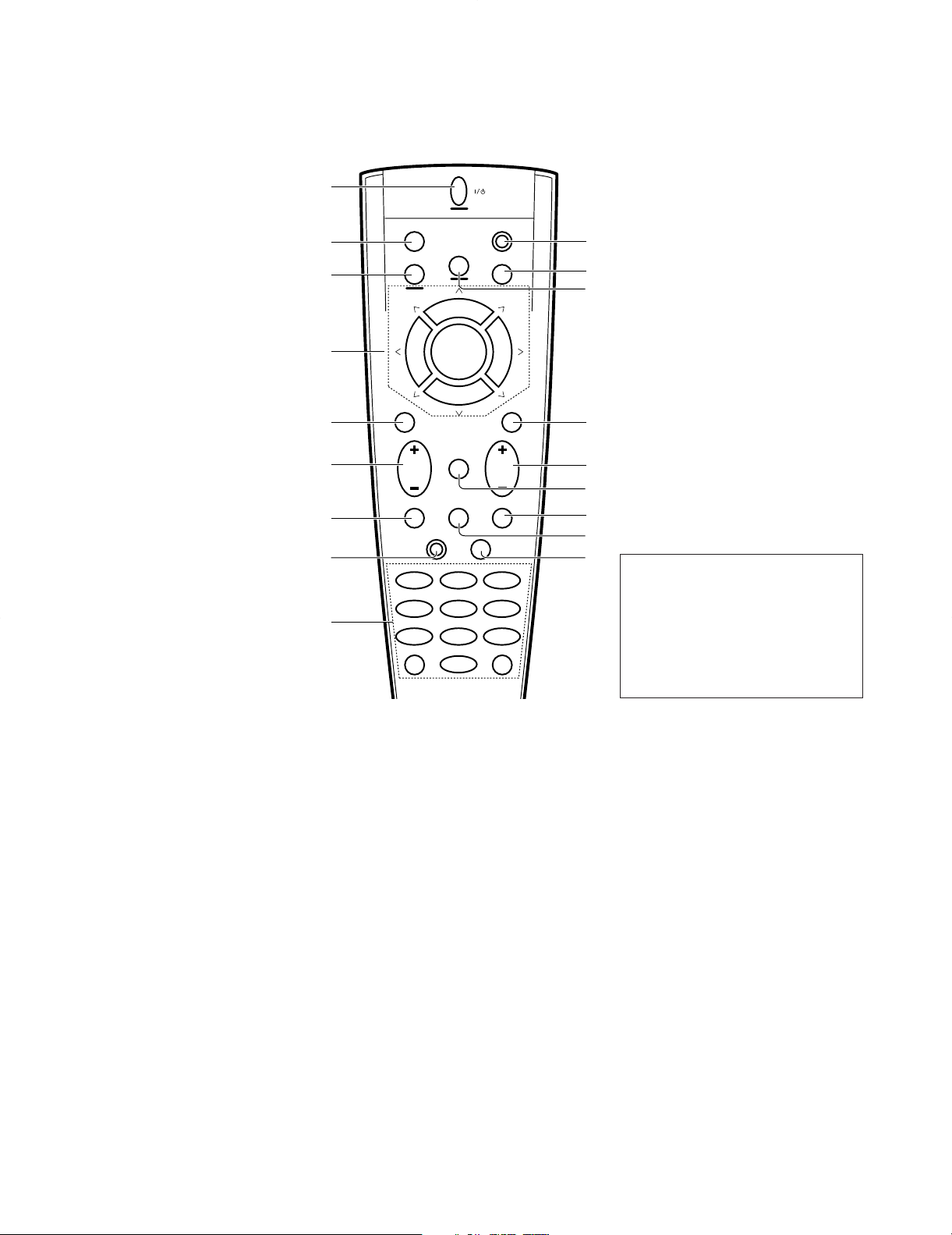
8 FUNCTION SHIFT key
Use in combination with the numeric keys
to execute alternate commands.
9 Numeric keys
Provide functions identical to those of the
original remote control supplied with the
component you are controlling.
To access the functions printed above the
keys, press within 3 seconds of pressing
the FUNCTION SHIFT key. Function availability varies for each component.
0 SHIFT key
Use in combination with the AUDIO and
VIDEO keys to change the remote control
mode without changing the input selector
or in combination with the POWER key to
turn on and off components programmed
into the remote control.
! TV selector key
Sets the remote control to operate a TV or
cable box. This key does not change the
input selector on the receiver.
@ AUDIO selector key
Selects the audio inputs and sets the remote control to operate the respective
KENWOOD audio component.
If you connect audio components from
KENWOOD and other makers to the MD/
TAPE or CD jacks, you can set the remote
control to operate these components by
registering the appropriate setup code at
the respective input.
# GUIDE key
Use to activate the OSD menu functions of
registered components.
$ VOLUME key
Use to adjust the receiver volume.
% MUTE key
Use to temporarily mute the sound.
^ SOUND key
Use to adjust the sound quality and ambience effects.
& LISTEN MODE key
Use to select the listening mode.
* SETUP key
Use to select the surround sound settings.
1 POWER key
Use to turn the receiver on and off.
Use in combination with the input selector
(AUDIO, VIDEO, or TV) keys and SHIFT
key to turn various components on and off.
2 MACRO key
Use in combination with the AUDIO, VIDEO,
or TV keys to execute a series of commands automatically (MACRO PLAY).
3 VIDEO selector key
Selects the video inputs and sets the remote control to operate the component
registered at the respective input.
4 Multi control keys
Use to operate the selected component.
5 REC key
Use to operate the selected component.
6 TUNING/SKIP key
Use during the setup procedure to specify
various settings. Use to operate the tuner
or selected component.
7 SUBWOOFER key
Use in combination with the VOLUME +/–
keys to adjust the volume of the subwoofer.
There are some cases in which keys (or
knobs) that have the same function on
the receiver and on the remote control
have different names. In the instructions of this manual, if the names of
corresponding keys (or knobs) on the
receiver and remote control are different, the name of the remote control key
is indicated in parentheses.
KRF-V8010D/V8010DW
CONTROLS
1
2
3
4
5
6
7
8
9
POWER
SHIFTMACRO
AUDIO
TVVIDEO
0
!
@
P. CALL P. CALL
8
BAND
6
4¢
7
MUTE
GUIDEREC
VOLUMETUNING/SKIP
#
$
LISTEN
MODE
SOUNDSUBWOOFER
%
^
FUNCTION
SHIFT
THEME FAVMENU
231
INFO ALT AUDTV/SAT/VID
564
REPEAT RANDOM+100
897
DISPLAY
0
SETUP
ENT+10
&
*
4
KRF-V8010D/V8010DW
1
2
2
4
4
4
3
3
x2
x2
x3
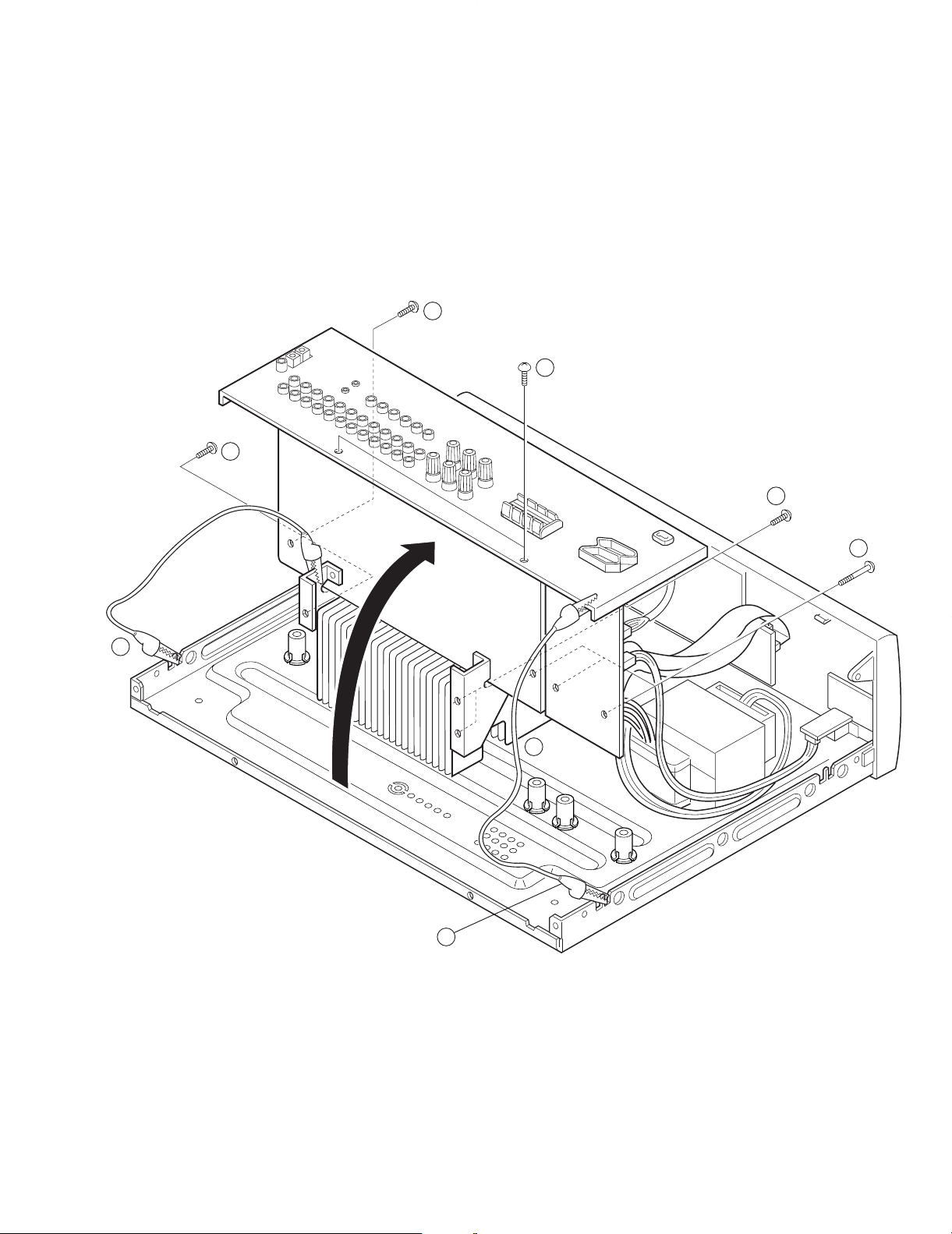
DISASSEMBLY FOR REPAIR
1. Remove the 8 screws (1,2,3),
remove the rear panel.
2. Connect the GND of the rear panel
and the chassis, the GND of the
mounting hardware and the chassis
with 2 alligators clip (4)
5
LFE
DA
AD
2
2
BYPASS
SW
C
LS/RS
L, R
L, R
L
R
C
LS
RS
SW
DIR
C LS/RS L/R
+
+
+
+
+
+
+
for 50W
4700uF
3300uF
for 50W
3300uF
4700uF
for 100W
ONLY
3300uF
470uF
2200uF
for 100W
ONLY
3300uF
470uF
+
2
IC2
ATT 2
ATT 1
ATT OFF
LINE BUF
PHONO EQ
TUNER
IC4
NJM2279M
CS4226
LPFLPF LPF LPF
x2x2 x2
x1
x0.6x0.3x0.3x1
SW MIX SW LPF
IC18
BUF
MIXx2
YSS248
DSP
ATT
x0.5
HPF
HPF
ATT
x0.6
M62446SP
6ch E. VOL
with
TONE CONT.
Lch
Rch
Cch
LSch
RSch
SWch
x0.5
BUF
STK411-230D
STK410-030D
10dB ATT MUTE
+B HITAP
B HITAP
+B LOWTAP
B LOWTAP
VIDEO3
COXIAL
OPTICAL
VIDEO2
IN
DIGITAL
VIDEO3
VIDEO2
VIDEO1
CD
PHONO
TAPE1
/MD
TAPE2
/MONI
PLAY
/MONI
TAPE2
/MD
TAPE1
VIDEO1
VIDEO3
VIDEO2
VIDEO1
VIDEO1
MONITOR
PLAY
REC
OUT
OUT
REC
Lch
H, P, Rch
H, P, Lch
Rch
Cch
Lch
Rch
SLch
SRch
SLch
SRch
Cch
SWch
REC OUT
SP-B
SP-A
AC IN
+5V
A.V.R
for
u-COM
+15V
A.V.R
A.V.R
15V
+5V
+7V
7V
A.V.R
+5V
for E. VOL
for
for E. VOL
for u-COM ( 30V)
for DSP, AD/DA, DIR
for FL
(AUDIO and VISUAL)
TUNER
for AMP (HI TAP)
AMP (LOW TAP)
ONLY for 100W
for
for RELAY SW
TC9163AF
TC9164AF
A1
J1
IC3
IC5
IC6(1/3)
2.5mV/27K
PHONO
IC21
IC23(2/2)
(1/2) (1/2)
(2/2)
IC22
IC6
AUDIO
200mV/47K
200mV/2.2K
IN
OUT
1VP-P/75
VIDEO IN/OUT
IC7(1/3)
IC6(2/3)
IC7(2/3)
IC11
IC8
IC6(3/3)
VIDEO SEL
K1
Q1
SWITCHED
S1
D1
D2
D5
IC1
IC2
30V A.V.R
IC8-10
Q2
IC1IC2
IC14
(2/2)
IC15
(2/2)
IC14
(1/2)
IC15
(1/2)
IC17
IC16
IC12
IC13
HPF
IC20
IC5 (1/2)
IC9
Q3
Q4
Q7
Q5
Q6
Q8
Q9
Q10
Q13
Q11
Q12
Q16
IC4
IC3
K1
K4
K2
1V/2.2K
2V/2.2KSWch
C, SL, SRch
PRE OUT
6ROTARY ENC
REMOCON IN
KEY MATRIX
FL
KEY RETURN
KEYSCAN
SEGMENT
GRID 11
3
8
7
LED
AC-3
CXP82852-134Q
u-COM
POWER RELAY
(RELAY FA, RELAY FB,
RELAY 4
(STANDBY
(TMUTE, PLLCE, PLLCLK,
MUTE
10dB ATT
VOL DT)
(VOL STB, VOL CLK,
E-VOL
VIDEO
RELAY C, RELAY S)
VMUTE)
(VIDEO A, VIDEO B,
3
3
(SCK,SI,SO,IC)
RESET
STEREO, SLEVEL)
PLLDT, PLLDO, PLLSD,
TUNER 8
5
E2ROM
(DATA, CLK)
PROTECTION
SYNCHRO
(SDATA, SBUSY)
DOL.DIG,P.LEVEL)
2
2
K3
IC51
ED51
IC7(3/3)
INPUT SEL.
UNIT
TC9162AF
DA&AD
DIR
CONVERTER
D1-4
T1
(1/2)
(2/2)
(1/2)
(1/2)
(2/2)
(2/2)
IC10
IC10
IC12
IC11
IC11
IC12
D3-6
SP. 5ch OUTPUT
E, T, Q
X 28.3V/8 (10%)
20V/4 (0.7%)
LS/RS
LINE BUF
IC31
C
LINE BUF
IC32 (1/2)
IC32 (2/2)
LINE BUF
SW
IC19
IC23 IC22
IC5
(2/2)
6ch
INPUT
DVD
15
0.5Vp-p/75COAX
DIGITAL INPUT
OPTICAL 21dBm
KRF-V8010D(E)
(X00)
(X08)
(AUDIO)
(VISUAL)
(X09)
(X08)
6
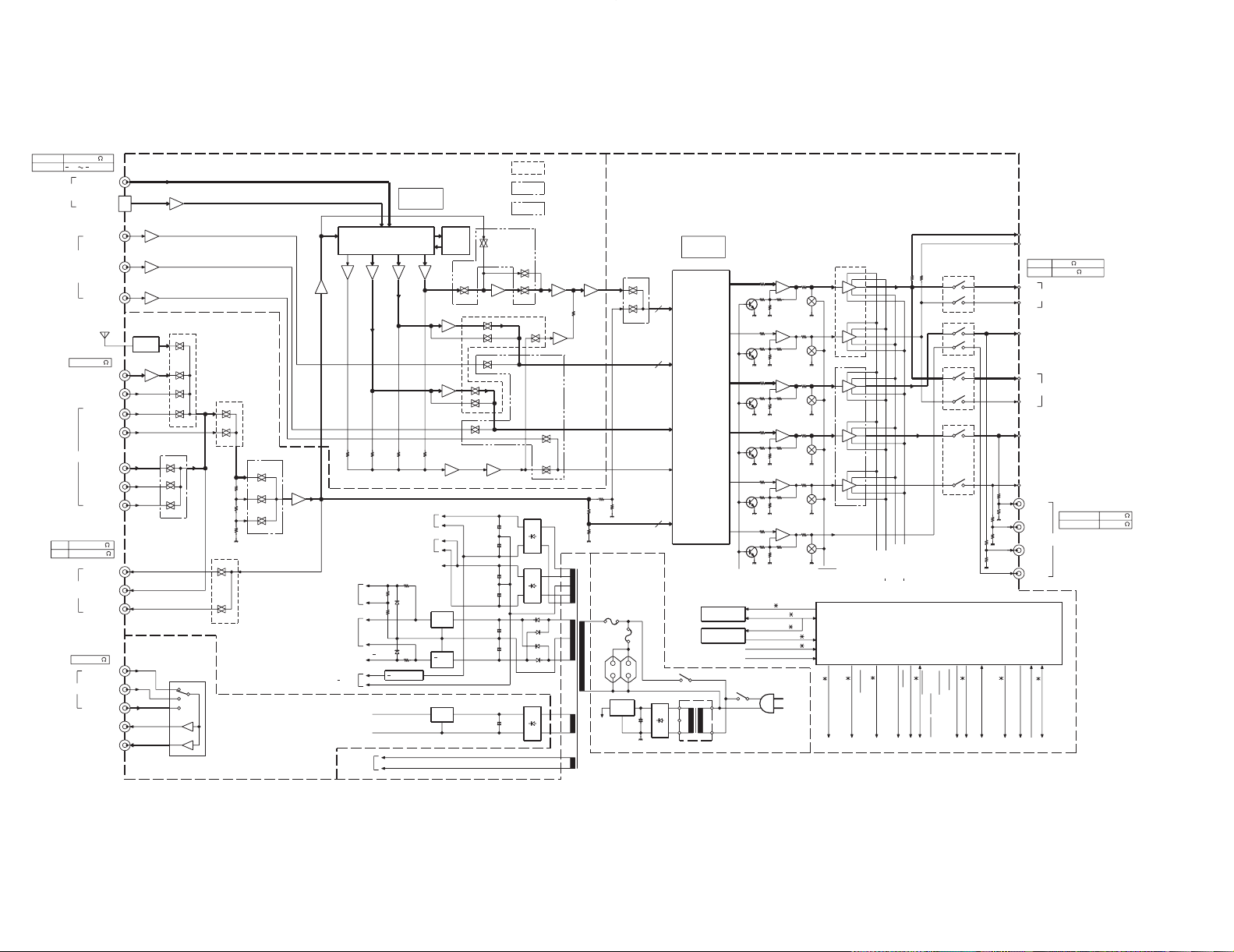
KRF-V8010D/V8010DW
BLOCK DIAGRAM
FL DISPLAY (X09) ED51
11GRID
17SEGMENT
X8
X3
X3
X4
X3
X3
X2
X2
X2
(X09) S517
SERIAL
BUSY
DATA
VOLUME
ENCODER
(X09) S519
MULTI
ENCODER
(X09) S518
SELECTOR
ENCODER
(X09)
X4
X1
X3
X3
8.0MHz
CE
RESET
X3
X1
X3
X2
(M TYPE ONLY)
AUDIO MUTE
TUNER MUTE
TUNER (X09) IC2
(X09) IC1
-10dB ATT
SD
STEREO
X1
11-MT-116GK
LED
(PEAK. LEVEL)
(DOLBY DIGITAL)
(STANDBY)
(X09) IC6,7
AUDIO SELECTOR
(X08) IC4
NJM2279M
(X09) A501
REMOCON
VIDEO SELECTOR IC
TC9163/9164
CXP82832-134Q
(X00) POWER Relay - (K1)
SP. A RELAY - (K1)
SP. B RELAY - (K2)
SURR RELAY - (K3)
CENTER RELAY - (K4)
(X08) IC1
DSP IC
(X08) IC2
DAC IC
YSS248
CS4226
(CRYSTAL)
(X09) IC5, 6
FUNCTION SW
(X09) IC9
VOLUME IC
(X09) IC52
E2PROM
M62446FP
LC72131
X24CO2
(XICOR)
TC9162/9164
12
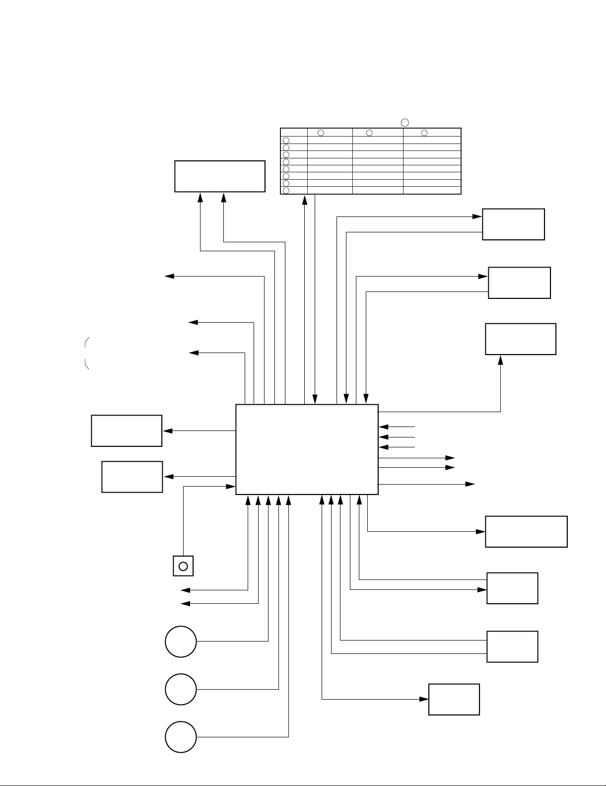
KR0
13
KR1
14
KR2
81
KS0 P.CH DOWN ON/STANDBY SPEAKER A
80
KS1 P.CH UP DIMMER SPEAKER B
79
KS2 BAND LISTEN MODE BASS BOOST
78
KS3 AUTO SOUND MONITOR
77
KS4 MEMORY SETUP SOURCE DIRECT
76
KS5 INPUT MODE
75
KS6 DSW0 DSW1 DSW2
74
KS7
* No. of : u -COM Port NO.
DSW3 DSW (AC3)
Key matrix
CIRCUIT DESCRIPTION
1. Microprocessor: CXP82832-134Q(X09 : IC51)
1-1 Microprocessor periphery block diagram
KRF-V8010D/V8010DW
7

KRF-V8010D/V8010DW
CIRCUIT DESCRIPTION
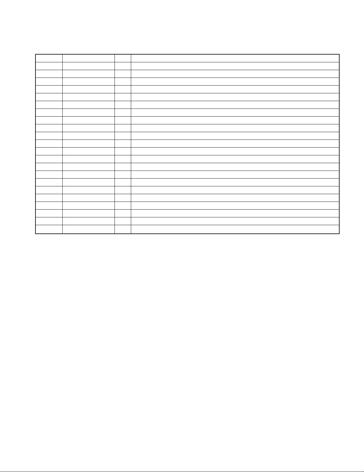
1-2 Pin description
Pin No. Pin Name I/O Description
1,2 G10,11 O Display grids 10,11
3 None – Ic test mode port.
4 CK I RDS clock input.
5 RDS. DT I RDS data input.
6 AUDIO I Audio signal detection port. L=AUDIO.
7 VOL.ENC.A I Volume encoder A(clockwise) input.
8 REMOCON I Remote contol signal input.
9 VOL.ENC.B I Volume encoder B(counterclockwise) input.
10,11 None O Ic test mode port.
12-14 KR0-2 I Key return 0-2.
15 PROTECT I Protection signal detection port. H=PROTECT.
16 S.DATA I/O Serial DATA signal.
17 S.BUSY I/O Serial BUSY signal.
18 E2.DT I/O E2 PROM data.
19 E2.CLK I/O E2 PROM clock.
20 SEL.ENC.A I Selector encoder A(clockwise) input.
21 SEL.ENC.B I Selector encoder B(counterclockwise) input.
22 MULTI.ENC.A I Multi encoder A(clockwise) input.
23 MULTI.ENC.B I Multi encoder B(counterclockwise) input.
24 AC3 I AC-3 signal detection.
25 AC3.SCK O YSS248 clock output.
26 AC3.SI I YSS248 data input.
27 AS3.SO O YSS248 data output.
28 Vdd – Analog power supply(+5V)
29 S. LEVEL I Signal level A/D input.
30 SEL.ST2 O TC9162AF/63AF/64AF st2 output. H=latch.
31 AC3.CS O YSS248 CS output.
32 CODEC.CS O CS4226 CS output.
33 PLL.DO I Pll ic do signal input port.
34 PLL.ST I Tuner stereo signal detection port. L=STEREO.
35 PLL.SD I Tuner sd signal detection port. L=TUNED.
36 RCV.CE I Receiver chip enable signal port. L=ENABLE.
37 Avss – Analog GND.
38 RESET I Microproessor reset signal.
39,40 8MHz I Main clock generation(8MHz).
41 Vss – Microprocessor GND.
42 None I No connect
43 TEX – GND.
44 Vdd – Power supply(+5V).
45 Vfdp – Power supply(-33V).
46 SEL.ST1 O TC9162AF/63AF/64AF st1 output. H=latch.
47 PLL.DT O Pll ic data signal output.
48 PLL.CK O Pll ic clock signal output.
49 PLL.CE O Pll ic ce signal output port.
50 T.TUNE O Tuner mute control. L=mute on.
51 A.MUTE O Output mute control. L=mute on.
52 SW.MUTE O Sub woofer mute control. L=mute on.
53 10dB.ATT O Volume 10dB attenuation control. H=att. on.
54 VOL.DT O Volume ic (M62446SP) data control.
8
55 VOL.CK O Volume ic (M62447SP) clock control. H=active.
KRF-V8010D/V8010DW
CIRCUIT DESCRIPTION
Pin No. Pin Name I/O Description
56 VOL.ST O Volume ic (M62448SP) st control. H=active.
57 VCR.MUTE O Video ic (NJU2279D) cont2/4 mute control. L=mute on.
58 VCR.A O Video ic (NJU2279D) cont1 mute control. H/L=static.
59 VCR.B O Video ic (NJU2279D) cont3 mute control. H/L=static.
60 FA.RLY O Front A speaker relay control. H=relay on.
61 FB.RLY O Front B speaker relay control. H=relay on.
62 C.RLY O Center speaker relay control. H=relay on.
63 S.RLY O Rear speaker relay control. H=relay on.
64 POWER.RLY O Power relay control. H=relay on.
65 STANDBY.LED O Standby led control.L=led on.
66 DOL.DIG.LED O Dolby digital led control.L=led on.
67 CLIP INDI. LED O Clip indicator led control.L=led on.
68 DVD 6CH LED O DVD 6CH input level control.
69-70 None O No connect
71 PACL_CTL O Non oscillation of power pack ic at power off. L=stop oscillation.
72 AC3.IC O YSS248/CS4226 initial clear port.
73 EMPHASIS O Tuner emphasis on/off. H=100k/10k,L=50k/9k.
74-81 P1-8 O Display segments 1-8 & key returns 0-7.
82-88 P9-15 O Display segments 9-15.
89 Vdd O Microprocessor power supply(+5V)
90,91 P16,17 O Display segments 16,17
92-100 G1-9 O Display grids 1-9.
9
KRF-V8010D/V8010DW
CENTER SPEAKERFRONT SPEAKERS
FM
75Ω
GND
AM
ANTENNA
ƒ
SYSTEM CONTROL
REC OUT
PHONO
DVD 6CH. INPUT
CD MD / TAPE
VIDEO 1VIDEO 1
VIDEO 2 VIDEO 3
VIDEO 1
VIDEO 2
DVD 6CH.
VIDEO 3
DVD 6CH.
VIDEO 2
DOLBY DIGITAL / PCM IN
VIDEO 3
SUBWOOFER
SUBWOOFER
SURROUND
SURROUND
SURROUND SPEAKERS
FRONT SPEAKERS
PRE OUTMONITOR
PLAY IN REC OUT PLAY IN REC OUT PLAY IN PLAY IN PLAY IN CENTER
CENTER
SL16
XS8
L
R
+
++
+
----
+
+
--
RAL C
L
L
R
L
R
R
L
R
B
MONITOR
VIDEO IN
VIDEO OUT
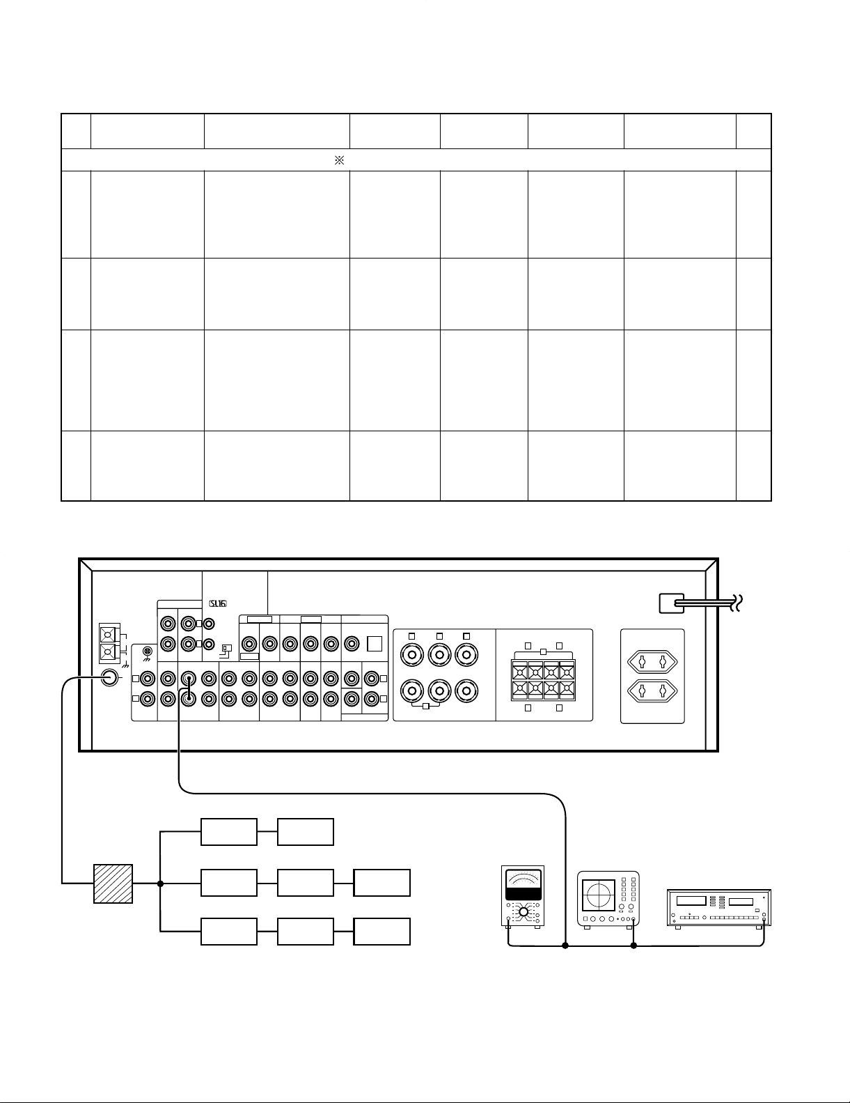
(A)
(B)
(C)
FM SG
FM SG
TV SG
AG
MPX
HTB
TV MPX
AG
AG
AC voltmeter
Oscilloscope
Distortion meter
Dummy antenna
(D)
No. ITEM INPUT SETTINGS
OUTPUT
SETTINGS
TUNER
SETTINGS
ALIGN FOR
FIG.
1 DISCRIMINATOR
(A)
98.0MHz 1kHz,
±40kHz dev.
Connect a DC
voltmeter
between CN2
1 and CN2 2
(TUNER UNIT)
MONO
98.0MHzL4 (TUNER UNIT)
0V (a)
3
DISTORTION
(STEREO)
98.0MHz
(C)
1kHz, ±40kHz dev.
Selector : L or R
Pilot : ±6kHz dev.
70dBf (ANT. input)
(B)
AUTO
98.0MHz
IFT
(TUNER
UNIT : A1)
Minimum distortion
(L or R)
(a)
2
DISTORTION
(MONO)
(A)
98.0MHz 1kHz,
±40kHz dev. MONO
70dBf (ANT. input)
(B)
MONO
98.0MHz
L5
(TUNER UNIT)
Minimum distortion
(a)
4 TUNING LEVEL
(A)
98.0MHz MONO 1kHz,
±40kHz dev.
25dBf (ANT. input)
(B)
MONO
98.0MHz
VR1
(TUNER UNIT)
Adjust VR1 and
stop at the point
where ED51
(TUNED) goes on.
(a)
FM SECTION SELECTOR : FM Adjust NO.1 and NO.2 repeat.
70dBf (ANT. input)
ADJUSTMENT
ALIGNMENT
POINTS
SYSTEM CONNECTIONS
10
 Loading...