

Kenwood KDCW-5041-UA, KDCW-5141-UAY, KDCW-5041-UG, KDCW-5541-U, KDCW-5641-UY Service manual
...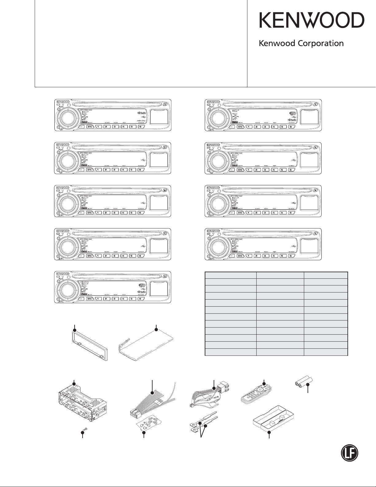
CD RECEIVER
KDC-MP408U/MP438U/X492
KDC-MP5039U/MP5539U
KDC-W5041UA/W5041UG
KDC-W5141UAY/W5141UGY
KDC-W5541U/W5641UY
SERVICE MANUAL
© 2008-2 PRINTED IN JA PAN
B53-0614-00 (N) 519
KDC-MP408U : Panel assy (A64-4400-02)
KDC-MP408U
KDC-MP5039U : Panel assy (A64-4402-02)
KDC-MP5039U
KDC-W5041Ux : Panel assy (A64-4404-02)
KDC-W5041U
KDC-W5541U : Panel assy (A64-4403-02)
KDC-W5541U
KDC-X492 : Panel assy (A64-4398-02)
KDC-X492
* Escutcheon
(B07-xxxx-xx)
* Carrying case
(W01-xxxx-xx)
KDC-MP438U : Panel assy (A64-4399-02)
KDC-MP438U
KDC-MP5539U : Panel assy (A64-4401-02)
KDC-MP5539U
KDC-W5141Uxx : Panel assy (A64-4406-02)
KDC-W5141U
KDC-W5641UY : Panel assy (A64-4405-02)
KDC-W5641U
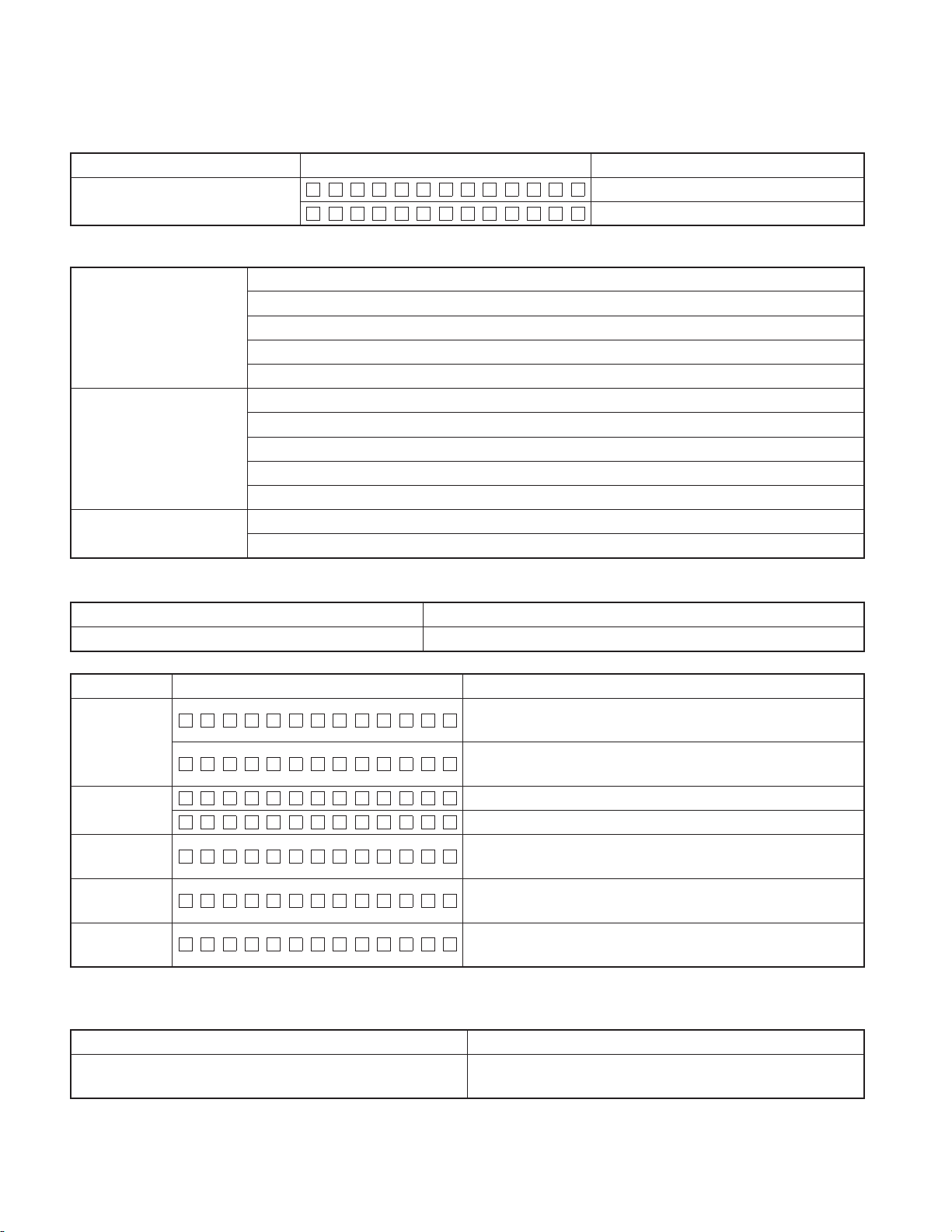
TDF SPARE-PANEL
MAIN UNIT NAME TDF PARTS No. TDF NAME
KDC-MP408U Y33-2920-62 TDF-MP84DT
KDC-MP438U Y33-2920-61 TDF-MP84D
KDC-MP5039U Y33-2920-64 TDF-MP5039U
KDC-MP5539U Y33-2920-63 TDF-MP5539U
KDC-W5041UA Y33-2920-66 TDF-W5041UA
KDC-W5041UG Y33-2920-67 TDF-W5041UG
KDC-W5141UAY Y33-2920-66 TDF-W5041UA
KDC-W5141UGY Y33-2920-67 TDF-W5041UG
KDC-W5541U Y33-2920-65 TDF-W5541U
KDC-W5641UY Y33-2920-65 TDF-W5541U
KDC-X492 Y33-2920-60 TDF-84DX
Mounting hardware assy
(J21-9716-03)
* Screw (4x16)
(N84-4016-48)
* Depends on the model. Refer to the parts list.
* DC cord
(E30-6428-05)
* Screw set
(N99-1757-15)
* DC cord
(E30-6671-05)
Lever
(D10-7012-04) x2
This product complies with the
* Remote controller assy (RC-547)
(A70-2085-05)
Battery
(Not supplied)
* Plastic cabinet assy
(A02-2755-13)
This product uses Lead Free solder.
RoHS directive for the European market.
KDC-MP408U/MP438U/X492/MP5039U/MP5539U/W5041UA/
2
W5041UG/W5141UAY/W5141UGY/W5541U/W5641UY
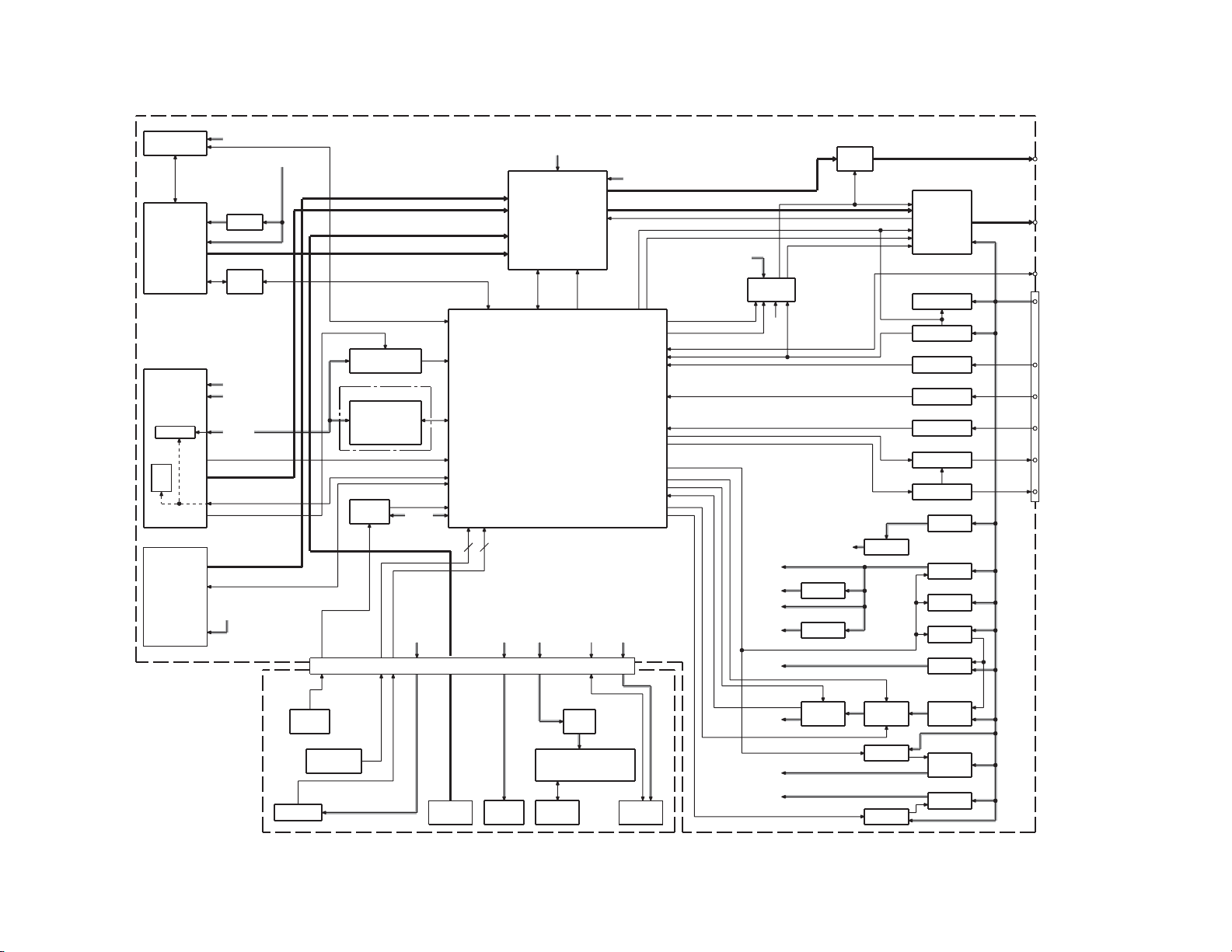
ELECTRIC UNIT (X34- )
DME1
CD
IC700
SOC
A320
FRONT-END
E2PROM
FST
MPX for RDS
J440
LX BUS
SERVO
IC720
D1.8V
IC680,682
LEVEL
SHIFT
AM+B
A8V
SW5V
BACK
UP
SWITCH UNIT
(X16- )
D3.3V
IC2
REMOTE
J660
S3
RESET
SW
J1
S1
ROTARY
ENCODER
IC300
RDS
DECODER
NOT USED
IC602
INSTALLER
MEMORY
ROM
CORRECTION
IC601
RESET
IC BU5V
PAN SW5
J3
AUX CN
IC600
21
CN
KEY KEY
ILLUMI
IC480
CH
FM/AM
AUX (FRONT)
CD
ILLUMI+B
ED1
A8V
E-VOL
SYSTEM
u-COM
FL+B
MATRIX
USB I/F
for SOC
(IC700)
R74,75
1/2W
Rx2
FL
4VPRE+B
PRE MUTE
USB5V
J4
USB CN
MUTE
BU5V
IC603
SERVO
MUTE
DRIVER
USB5V
Q367,368,401,402,411,412
RST
Q100,103
4VPRE
Q320,321
AM+B
HI-SIDE
SW
PRE
MUTE
Q104
Q105
Q22,23
P.ON5V
IC60IC230
USB 5V
FDC
SW 14V
SW 14V
IC500
POWER
IC
OFFSET
Q120
BU DET
Q123
SURGE DET
C160,R160,R161,D160
TEL MUTE
Q122
ACC DET
Q170
DIMMER
Q150,151
ANT-CON
Q140,143
P-CON
Q20,21
BU 5V
Q10-12
A8V
Q33
SW 14V
Q32
SW 14V
Q30,31
SERVO
Q50,51
SW 20V
Q101
4VPRE
+B
Q40-43
ILL+B
J400
WH190
PRE OUT
(FRONT)
PRE OUT
(REAR)
PRE OUT
(SW)
SP OUT(FL)
J1
SP OUT(FR)
SP OUT(RL)
SP OUT(RR)
WIRED
REMOTE
J1
BACK UP
LINE
ACC
DIMMER
ANT CON
P. CON
BLOCK DIAGRAM
KDC-MP408U/MP438U/X492/MP5039U/MP5539U/W5041UA/
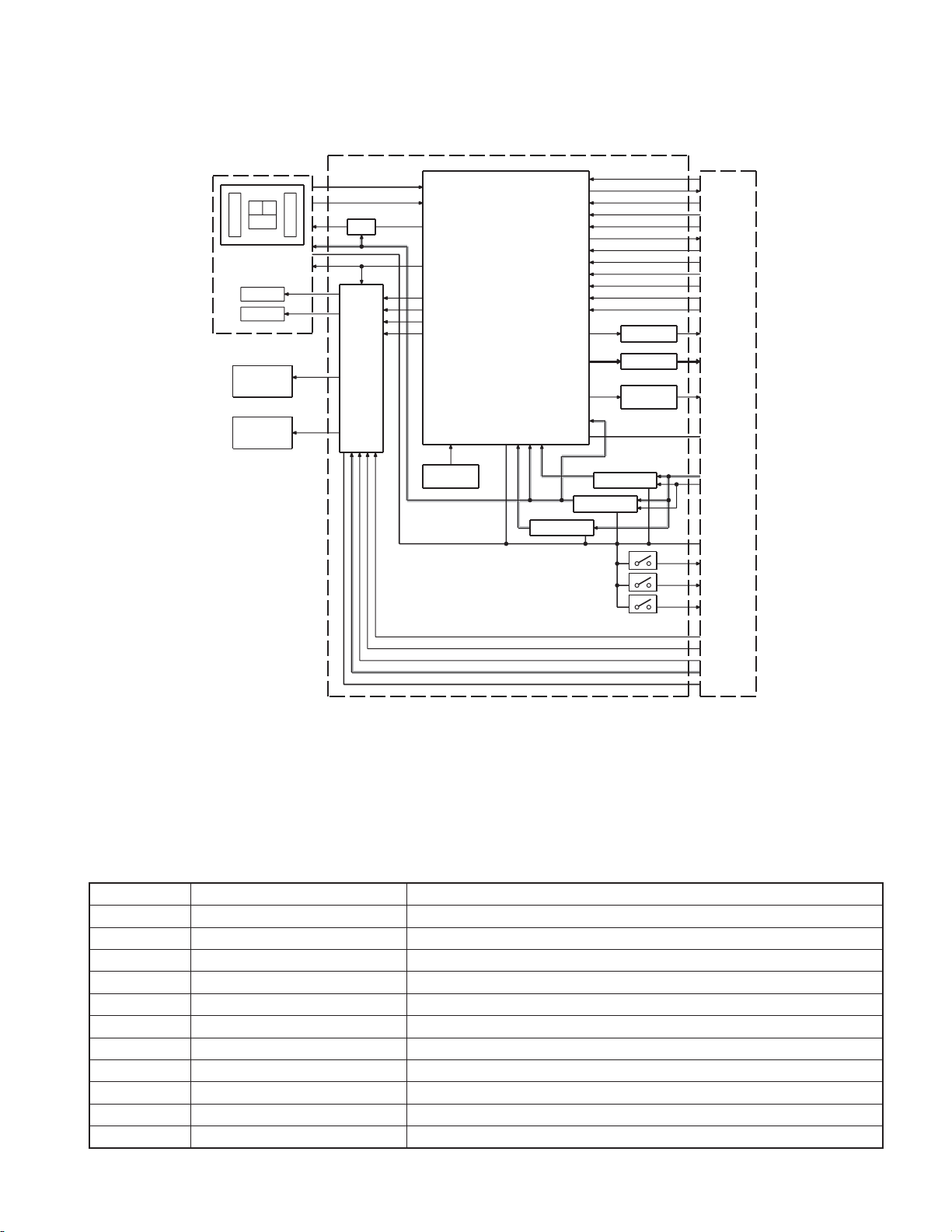
BLOCK DIAGRAM
W5041UG/W5141UAY/W5141UGY/W5541U/W5641UY
DPU1
ACB
EF
FO COIL
TR COIL
DM1
LOADING &
SPINDLE
MOTOR
DM2
LOADING &
SLED
MOTOR
CD PLAYER UNIT (X32-6130-00)
IC4
SIGNAL
A,B,C,E,F
Q1
APC
IC3
FO OUT
TR OUT
MOTOR
DRIVER
DM OUT
FM OUT
PD
LD
VREF
FO OUT
TR OUT
DM OUT
FM OUT
X1
CLOCK
16.934MHz
RF AMP
SERVO
PROCESSOR
MP3 DECODER
WMA DECODER
AAC DECODER
1M bit SRAM
MOTHER
BOARD
(X34- )
SRAMSTB
SO
SI
BUCK
CCE
PIO0
+
+
+
+
+
D GND
MRST MRST
BSIF ST REQ
BSIF GATE
BSIF DATA
BSIF BCK
BSIF LRCK
R-ch
L-ch L-ch
ZDET MUTE L/R
A3.3V
AGND
BU1.5V
SW1.5V
SW3.3V
IC6
IC11
BU1.5V REG
IC5
SW1.5V REG
SW3.3V REG
C88,R82
CR FILTER
C87,R83
CR FILTER
Q13
REVERSAL
CIRCUIT
SRAMSTB
SO
SI
BUCK
CCE
PIO0
BSIF ST REQ
BSIF GATE
BSIF DATA
BSIF BCK
BSIF LRCK
R-ch
A8V
A.GND
BU5V
P.ON
D.GND
S1
LOS-SW
S2
12EJE-SW
S3
LOE-SW
8EJE-SW
DRV MUTE
LO/EJ
MOTOR
S7.5V
S.GND
COMPONENTS DESCRIPTION
ELECTRIC UNIT (X34-577x-xx)
●
Ref. No. Application / Function Operation / Condition / Compatibility
IC10 A8V REF Power Supply Outputs 1.27V.
IC20 D3.3V REG Outputs 1.8V. Power supply for SOC.
IC60 SW REG Outputs 5.0V. Power supply for D5V, FL+B and USB5V.
IC100 OP-AMP Reference supply for 4V pre-out.
IC230 Hi-side SW Overcurrent protection of USB power supply. When pin4 goes Hi, USB5V is ON.
IC300 RDS Decoder Decodes RDS signal.
IC480 E-VOL Controls the source, volume and tone.
IC500 Power IC Amplifi es the front L/R and the rear L/R to 50W maximum.
IC600 System μ-COM Controls FM/AM tuner, the changer, CD mechanism, USB, panel, volume and tone.
IC601 Reset IC Lo when detection voltage goes below 3.6V.
IC603 Muting Logic IC Controls logic for muting.
3
KDC-MP408U/MP438U/X492/MP5039U/MP5539U/W5041UA/
W5041UG/W5141UAY/W5141UGY/W5541U/W5641UY
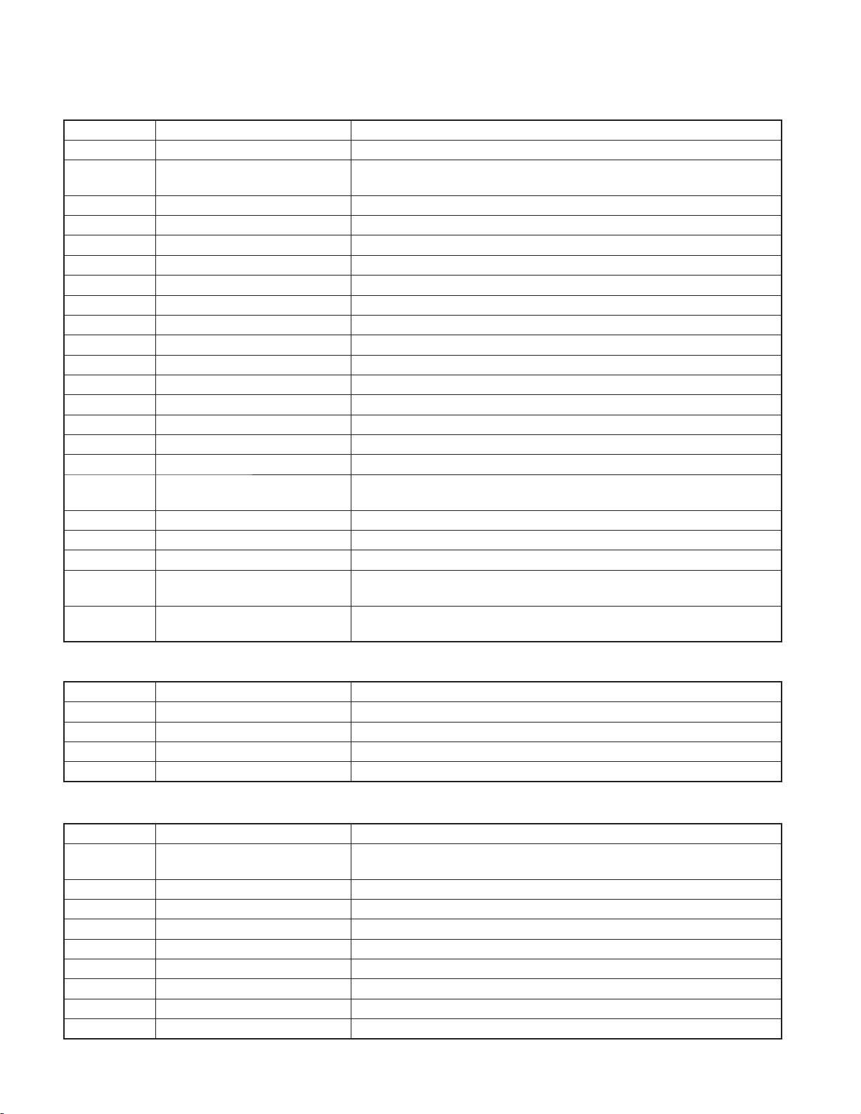
COMPONENTS DESCRIPTION
Ref. No. Application / Function Operation / Condition / Compatibility
IC680,682 Level Shift Converts 3.3V to 5V.
IC700 SOC (System On Chip)
IC750 iPod Authentication Coprocessor For iPod authentication.
Q10~12 A8V AVR When Q12’s base goes Hi, A8V AVR outputs 8.0V.
Q20,21 BU5V AVR While BU is applied, BU5V AVR outputs +5V.
Q22,23 P.ON5V When Q23’s base goes Hi, SW5V outputs +5V.
Q30,31 Servo+B AVR When Q31’s base goes Hi, Servo+B AVR outputs 7.5V.
Q32,33,104,105 SW14V When Q33’s (or Q105’s) base goes Hi,SW14V outputs 14V.
Q40~43 ILL+B AVR When Q43’s base goes Hi, ILL+B outputs 10.5V.
Q50,51 Serge Protect for IC1 Output 20V when BU is over 20V.
Q100,103 4VPRE+B Protect When 4VPRE+B is overcurrent, Q100 and Q103 turn Q101 off.
Q101 4VPRE+B AVR When Q100’s base is 8V, 4VPRE+B outputs 7.4V.
Q120 BU DET When the base goes Hi, Q120 is turned on.
Q122 ACC DET When the base goes Hi, Q122 is turned on.
Q123 Serge DET When the base goes Hi, BU DET is turned off.
Q140,143 P-CON SW When Q143’s base goes Hi, AVR outputs 14V.
Q141,142 P-CON Protection
Q150,151 P-ANT SW When Q151’s base goes Hi, P-ANT SW outputs 14V.
Q170 Small Lamp DET SW When the base goes Hi, Q170 is turned on.
Q320,321 AM+B When Q321’s base goes Hi, AM+B is output.
Q367,368,401,
Q402,411,412
Q500
Pre-out Mute SW When a base goes Hi, pre-out is muted.
Electric Discharge Circuit for C508
(SVR)
Decodes MP3 or other fi les of audio/decompression standards by software based
architecture.
When P.CON output voltage decrease is detected, output protection is made.
When P.CON SW is ON, malfunction of Q140 is protected.
When the base goes Lo, Q500 is turned on.
SWITCH UNIT (X16-622x-xx)
●
Ref. No. Application / Function Operation / Condition / Compatibility
IC2 Remote Control Sensor
Q5,21 PAN5V SW When Q5’s base goes Hi, PAN5V outputs 5V.
Q20 VFD Restart In condition of the base is Hi, key-scan starts at the same time as POWER ON.
Q22~24 Grid Driver When each transistor’s base is Lo, grid is ON.
CD PLAYER UNIT (X32-6130-00)
●
Ref. No. Application / Function Operation / Condition / Compatibility
IC3 4ch BTL Driver
IC4 Servo DSP with built-in Audio DAC With built-in MP3/WMA/AAC decoder and 1M-bit-SRAM.
IC5 D1.5V REG. Power supply for digital 1.5V.
IC6 D3.3V REG. Power supply for digital 3.3V.
IC11 BU1.5V REG. Power supply for back-up 1.5V.
Q1 APC (Auto Power Control) Drives LD (Laser Diode).
Q13 Inverter Inverts ZDET signal.
D2 Laser Diode Protection Prevents reverse bias which is applied to laser. Laser destruction prevention.
D3,4 Static Electricity Countermeasure Prevents malfunction by static electricity.
Driver for focusing & tracking coil, driver for sled & spindle motor, and operation for
disc loading & ejection.
4

KDC-MP408U/MP438U/X492/MP5039U/MP5539U/W5041UA/
W5041UG/W5141UAY/W5141UGY/W5541U/W5641UY
MICROCOMPUTER’S TERMINAL DESCRIPTION
SYSTEM μ-COM: IC600 on X34- (ELECTRIC UNIT)
●
Pin No. Pin Name I/O Application
1 REMO I
2 LX REQ M O Communication request to slave unit
3-5 NC - Not used Output L fi xed
6 BYTE -
7 CNVSS -
8 XCIN - Sub clock 32.768kHz
9 XCOUT - Sub clock 32.768kHz
10 RESET -
11 XOUT - Main clock 12.00MHz
12 VSS -
13 XIN - Main clock 12.00MHz
14 VCC1 -
15 NMI -
16 LX REQ S I Communication request from slave unit
17 RDS CLK I RDS decoder clock input
18 PANEL DET I Detection of panel connector detached/attached H: Panel detached, L: Panel attached
19 PON AM I/O AM power supply control AM reception: H, No AM reception: Hi-Z
20 TUN IFC OUT I Front-end IFC-OUT input H: Station found, L: No station
21 RDS AFS M I/O Noise detection time constant SW
22 RDS QUAL I/O RDS decoder QUAL input
23 RDS DATA I RDS decoder data input
24 USB SYNC O Clock output for SW-REG
25,26 NC - Not used Output L fi xed
27 TUN SCL I/O Front-end I2C clock input/output MAX 400kHz
28 TUN SDA I/O Front-end I2C data input/output
29 VFD DATA I/O VFD data input/output
30 VFD INT I VFD INT input
31 VFD CLK O VFD clock output 125kHz
32 ROTARY CCW I VOL key detection
33 S SYS DATA O Bolero serial output
34 S SOC DATA I Bolero serial input
35 S SOC SCL I Bolero serial clock input
36-38 NC - Not used Output L fi xed
39 ROMCOR DET I E2PROM and Bolero writing request H: Writing
39 EPM I EPM input when writing
40 NC - Not used
41 VFD RST O VFD reset H: Reset cancelled, L: Reset
External display remote control input
Panel remote control input
Truth Value
Table
Processing / Operation / Description
Detects Pulse
15-pulse/360°, 2-click/1-pulse
5
KDC-MP408U/MP438U/X492/MP5039U/MP5539U/W5041UA/
W5041UG/W5141UAY/W5141UGY/W5541U/W5641UY
MICROCOMPUTER’S TERMINAL DESCRIPTION
Pin No. Pin Name I/O Application
42 ROTARY CW I VOL key detection
43 CD MUTE I CD mute request L: Mute request (Bolero), H: Normal condition
44 VFD CE O VFD control request H: VFD data transfer ready
45 NC - Not used Output L fi xed
46 PON O Power supply control H: Power ON, L: Power OFF
47,48 NC - Not used Output L fi xed
49
50,51 NC - Not used Output L fi xed
52 CD LOEJ I/O CD motor control
53 CD MOTOR O CD motor control
54 CD LOS SW I CD loading detection
55
56 PON PANEL I/O Panel 5V power supply
57 NC - Not used Output L fi xed
58 SOC S RST O SOC reset H: Normal condition, L: Reset (Bolero)
59 PON ILL O Key illumination power supply H: Power ON, L: Power OFF
60 VCC2 -
61 SOC S STOP O SOC stop H: Normal condition, L: SOC stopped (Bolero)
62 VSS -
63 TYPE 1 I Destination setting
64 TYPE 2 I Destination setting
65 NC - Not used Output L fi xed
66 ANT CON O Power antenna control Tuner ON: H
67 PCON O External amplifi er control
68,69 NC - Not used Output L fi xed
70 ILLUMI DET I Dimmer illumination detection L: ON, H: OFF
71 NC - Not used Output L fi xed
72 ACC DET I ACC power supply detection ACC found: L, No ACC: H
73 BU DET I Detection of momentary power down BU found: L, Momentary power down: H
74 S SYS REQ O Communication request of system μ-com → SOC
75 S SOC REQ I Communication request of SOC → system μ-com
76 PWIC SVR O Power IC discharge circuit control H: ON, L: OFF
77 PWIC MUTE O Power IC mute control
78 PWIC STBY O Power IC standby control
79 LINE MUTE I Line mute detection TEL mute: Below 1V, NAVI mute: Over 2.5V
80 PWIC DC DET I DC offset detection
81 IC2 SDA I/O I2C data input/output
82 IC2 SCL I/O I2C clock input/output
CD LOE LIM SW
CD DISC12 SW
I CD detection (Chucking SW) H: Loading completed, L: No disc
I 12cm CD detection
Truth Value
Table
q
q
Processing / Operation / Description
Detects Pulse
15-pulse/360°, 2-pulse/1-click
Refer to the truth value table
Refer to the truth value table
ON (For 11 minutes after ACC OFF): L
Momentary power down or Panel detached or
11 minutes after ACC OFF: Hi-Z
6
KDC-MP408U/MP438U/X492/MP5039U/MP5539U/W5041UA/
W5041UG/W5141UAY/W5141UGY/W5541U/W5641UY
MICROCOMPUTER’S TERMINAL DESCRIPTION
Pin No. Pin Name I/O Application
83,84 NC - Not used Output L fi xed
85 MUTE 0 O E-VOL front mute L: ON, H: OFF
86 MUTE 1 O E-VOL rear mute L: ON, H: OFF
87 MUTE 2 O E-VOL SW mute L: ON, H: OFF
88 MUTE PRE FR O PRE-OUT mute for FR
89 MUTE PRE SW O PRE-OUT mute for SW L: Mute ON, H: Mute OFF
90 RDS NOISE I FM noise detection
91 TUN SMETER I S-meter input
92 LX MUTE I Communication request from slave unit H: Mute ON, L: Mute OFF
93 LX CON O Start-up request to slave unit H: Slave unit ON, L: Slave unit OFF
94 AVSS -
95 LX RST O Forced reset to slave unit H: Reset, L: Normal condition
96 VREF -
97 AVCC -
98 LX DATA S I Data from slave unit
99 LX DATA M O Data to slave unit
100 LX CLK I/O LX-BUS clock
Truth Value
Table
Processing / Operation / Description
Mute is L during CD play: L
Momentary power down: L
Only condition when DUAL ZONE or NAVI INT:
H fi xed
Truth value table
CD motor control
q
CD MOTOR (Pin53) CD LOEJ (Pin52)
Stop L L
Load H L
Eject H H
Brake H Hi-z
7
KDC-MP408U/MP438U/X492/MP5039U/MP5539U/W5041UA/
W5041UG/W5141UAY/W5141UGY/W5541U/W5641UY
TEST MODE
Example
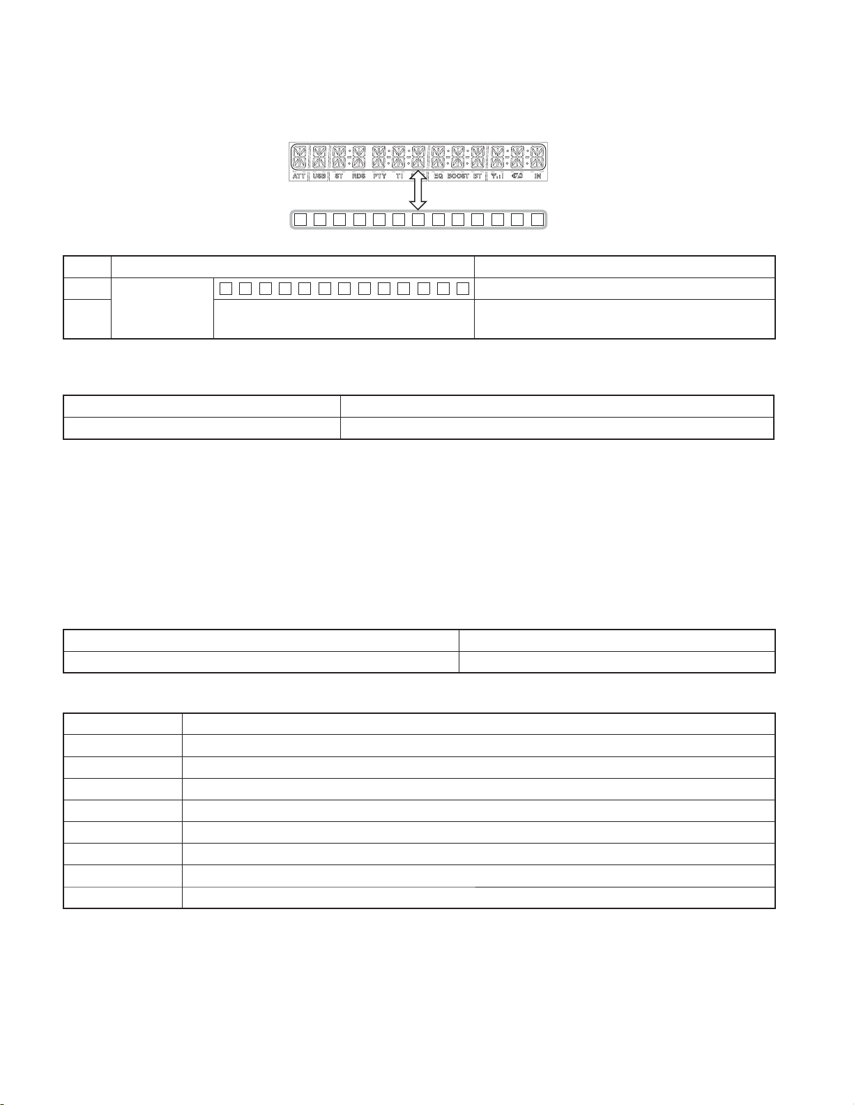
■
÷÷÷÷÷÷÷
Key Description of display Description
5
Disc EJECT times
display
5
■
A symbol “■” in the key column indicates that the key should be pressed and held for 1 second or longer.
How to enter the test mode
■
Procedure Note
Press and hold the [1] key and [3] key and reset. While “– – – –” is displayed, power can be turned ON for only 30 minutes.
EJECNT XXXXX
Disc EJECT times display. MAX 65535 (times)
While disc EJECT times is displayed, press and hold for 2
seconds or longer to clear disc EJECT times.
All lamps blink when it is detected that the sub-clock resonator is disconnected.
Do not display “CODE_OFF”, “CODE_ON” or “CODE_NG” when Power is ON.
When having started up in the test mode, change the LINE MUTE inhibition time from 10 seconds to 1 second.
When operating in the test mode, even if a DC offset error occurs, detection information is not written in the E2PROM.
When operating in the test mode, CD mechanism error log information clear mode, and DC offset error detection information clear mode, do
not perform DEMO mode operations.
Also, do not display DEMO ON/OFF option items in the MENU in STANDBY source in the above modes.
Forced load operation is prohibited in the test mode.
How to clear the test mode
■
Procedure Note
Reset, momentary power down, ACC OFF, Power OFF, Panel detached. Clearing the test mode
Test mode default condition
■
Description Default values
Source STANDBY
Display Display lights are all turned on.
Volume -10dB (“30” is displayed.)
Loudness OFF
CRSC OFF regardless of having/not having the switching function.
AUX ON
System Q NATURAL (FLAT)
Preout Rear
8
KDC-MP408U/MP438U/X492/MP5039U/MP5539U/W5041UA/
W5041UG/W5141UAY/W5141UGY/W5541U/W5641UY
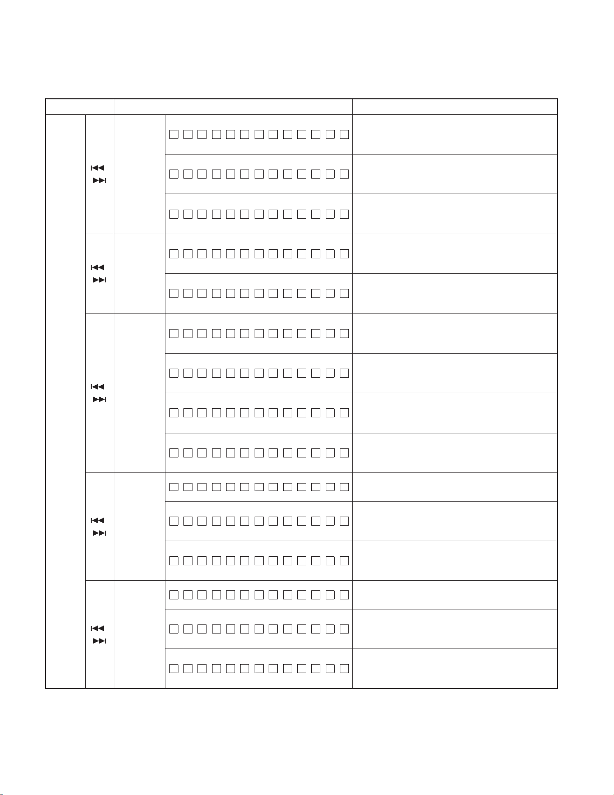
TEST MODE
Special displays when all lights are on in STANDBY source
■
Key Description of display Description
Common
All lights ON.
Destination terminal
condition indication
1
Development ID
condition indication
2 Serial No. display
3
Power ON time
display
3
■
4
Disc operation
time display
4
■
5
Disc EJECT times
display
5
■
6
Panel open/close
times display
6
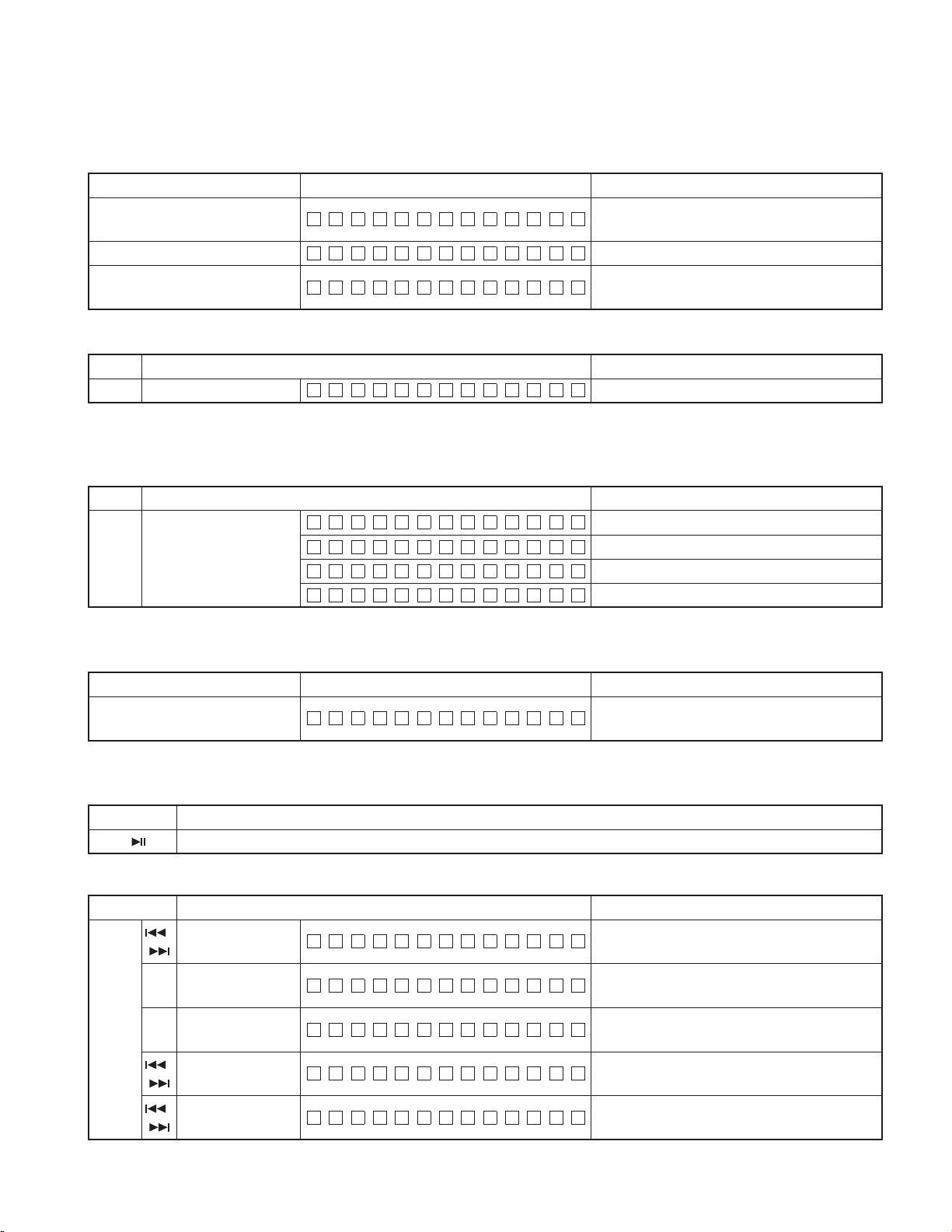
■
ROM correction
FM
version display
Audio data
initialization
Forced Power
OFF
information
display
■
CD information
display mode
ON/OFF
■
Information display
iPod authentica-
AUD
tion IC installation
status display
T Y P E 2:1 T Y P E 1:1
C0747WE2 – 3.00
SNO 00000000
PONT I M 0HX X
PONT IM XXXXX
CDT I M 0H XX
CDT IM XXXXX
EJECNT XXXXX
PNCNT XXXXX
S: R0001M:R0001
S:ERR M:ERR
S
S:R
AUDIO INIT
POF F – – –
POF F SEC
POF F PNL
÷÷÷÷÷÷÷
System μ-com Mecha μ-com
:R––––M:R––––
∗∗∗∗
iPod:OK
iPod:NG
M:R
∗∗∗∗
All lights ON.
“TYPE” indicates system μ-com (IC1) destination, and
shows real-time condition of the destination terminal.
Development ID – Version (system μ-com: IC1)
Serial No. is displayed (8 digits)
00~50 is displayed for “XX”. When less than 1 hour,
displayed by increments of 10 minutes.
00001~10922 is displayed for “XXXXX”. MAX 10922 (hours)
When Power ON time is displayed, press and hold for
2 seconds or longer to clear Power ON time.
00~50 is displayed for “XX”. When less than 1 hour,
displayed by increments of 10 minutes.
00001~10922 is displayed for “XXXXX”. MAX 10922 (hours)
While the disc operation time is displayed, press and hold
for 2 seconds or longer to clear the disc operation time.
(Cleared only for displayed media.)
Disc EJECT times display. MAX 65535 (times)
While disc EJECT times is displayed, press and hold for
2 seconds or longer to clear disc EJECT times.
PANEL open/close times display. MAX 65535 (times)
Press the key for more than 2 seconds while the PANEL
open/close count is displayed and PANEL open/close count
is cleared.
The number is the ROM correction version number.
When E2PROM is not installed.
When not written in yet.
When data not matched. (due to the difference in versions)
AUDIO setting value is re-set to the test mode default
value.
No forced power OFF
Forced power OFF because of missing Security Code.
Forced power OFF by communication error between
system μ-com and panel.
While the forced power OFF data is displayed, press and
hold for 2 seconds to clear the data.
For the display contents, refer to “CD information display
mode” in the next section.
While in CD information display mode, press and hold for
2 seconds or longer to clear all CD information.
iPod authentication IC installation status display
OK: The IC is installed, NG: The IC is not installed.
(When key is pressed while the display in the left is being
shown, returns to normal display.)
9
KDC-MP408U/MP438U/X492/MP5039U/MP5539U/W5041UA/
W5041UG/W5141UAY/W5141UGY/W5541U/W5641UY
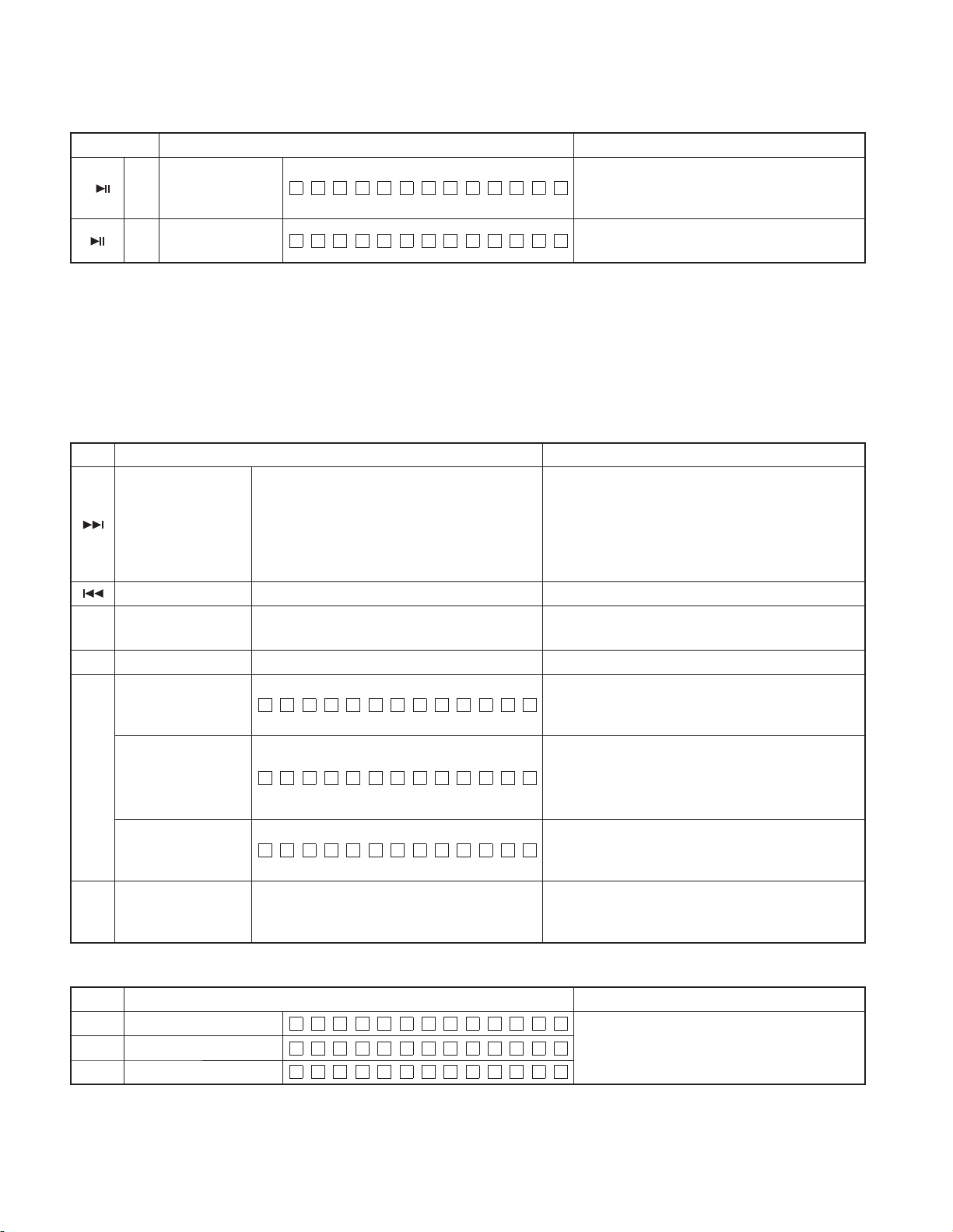
• CD information display mode
Key Description of display Description
MECH A ERR 1 :X X
CD mecha-
FM
(forward
rotation)
AM
(reverse
rotation)
/
nism error
log display
CD Load
/
error
information
display
CD Ejection
/
error
information
display
CD time
code error
/
count data
display
(Missing
counts)
CD time
code error
/
count data
display
(count not
updated)
MECH A ERR 2 :X X
MECH A ERR 3 :X X
LOAD ERR1 :XX
LOAD ERR2 :XX
EJECT ERR1 :XX
EJECT ERR2 :XX
EJECT ERR3 :XX
EJ ECT ERR4 :XX
CNT LO SE
CDDA :XX
CDROM :XX
CNT STAY
CDDA :XX
CDROM :XX
TEST MODE
Mechanism error log 1 (Latest)
XX: Error number. “– –” is displayed in case there is no
error.
Mechanism error log 2 (Latest)
XX: Error number. “– –” is displayed in case there is no
error.
Mechanism error log 3 (Latest)
XX: Error number. “– –” is displayed in case there is no
error.
Load error switch 1
XX: Number of errors. “– –” is displayed in case there
is no error.
Load error switch 2
XX: Number of errors. “– –” is displayed in case there
is no error.
Ejection error switch 1
XX: Number of errors. “– –” is displayed in case there
is no error.
Ejection error switch 2
XX: Number of errors. “– –” is displayed in case there
is no error.
Ejection error switch 3
XX: Number of errors. “– –” is displayed in case there
is no error.
Ejection error switch 4
XX: Number of errors. “– –” is displayed in case there
is no error.
CD time code error count data (Missing counts) mode
display.
Number of CD-DA count errors
XX: Number of errors. “– –” is displayed in case there
is no error.
CD-ROM (Compressed fi le) number of count errors
XX: Number of errors. “– –” is displayed in case there
is no error.
CD time code error count data (count not updated)
mode display.
Number of CD-DA count errors
XX: Number of errors. “– –” is displayed in case there
is no error.
CD-ROM (Compressed fi le) Number of count errors
XX: Number of errors. “– –” is displayed in case there
is no error.
10
KDC-MP408U/MP438U/X492/MP5039U/MP5539U/W5041UA/
W5041UG/W5141UAY/W5141UGY/W5541U/W5641UY
TEST MODE
Test mode specifi cations in TUNER source
■
Error is found in front-end (A1), etc. if indications below is displayed while in tuner source.
Status Display Description
Front-end (A1) E2PROM data error
Front-end (A1) communication error
Destination mismatch
TNE2P NG
TNCON NG
TNTYP NG
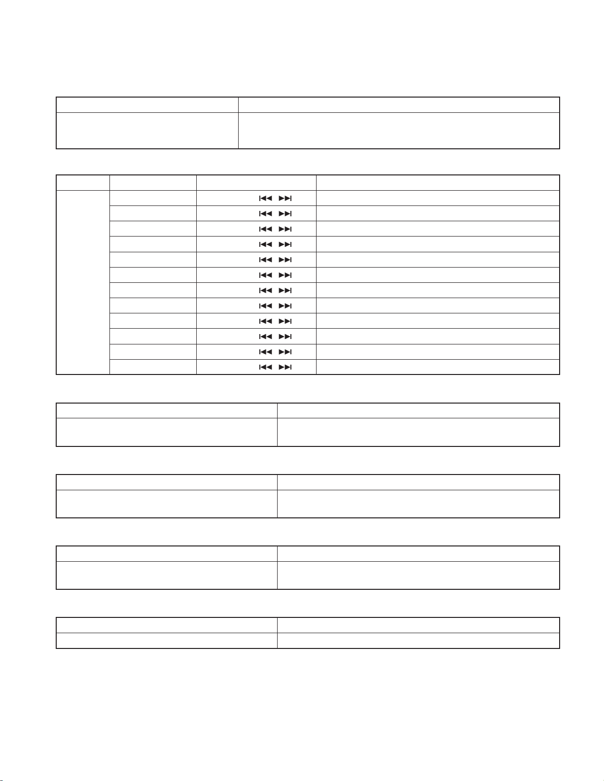
• TUNER preset operation
Key Description of display Description
4 Preset function
F M # 9 8.3 A :4
• K3I forced switching
Every time when [6] key is pressed in tuner FM source, switched in the following order: AUTO → Forced WIDE → Forced MIDDLE → Forced
NARROW → AUTO. Default status is AUTO, and displayed as shown below.
Key Description of display Description
FM1 9 8.1A
6 K3I Forced switching
FM1 9 8.1W :
FM1 9 8.1M :
F M 1 9 8.1 N :
Front-end (A1) E2PROM is still the default
(unspecifi ed) value.
Communication with front-end (A1) is not possible.
When destination is mismatch between front-end
(A1) E2PROM and the product.
Change to 98.3MHz with the preset key [4].
:
AUTO
Forced WIDE
Forced MIDDLE
Forced NARROW
• RDS auto measurement (KDC-W5xxx only)
Add the process to replace the visual inspection of PS display previously done in the production line.
Status Display Description
PS data reception
FM1 RD S TE S T:
If displayed as shown at the left, force to OFF.
P-CON is recovered by Power OFF/ON.
• FST adjustment mode
Perform FST soft-mute adjustment.
Key Note
■
Operations in the FST adjustment mode are as follows:
Key Description of display Description
FM
(UP)
AM
(DOWN)
Enter the FST adjustment mode. (Press for 1 second or longer.)
/ Soft-mute
adjustment
Seek Stop Level
adjustment (Auto)
Seek Stop Level
adjustment (Auto)
/ Seek Stop Level
adjustment (Manual)
/ Seek Stop Level
adjustment (Manual)
SMD – F
ATN V
ATL V
MNN V
MN L V
0 ↔ 7
0.00 (V) ↔ 5.00 (V). Normal (Local OFF)
0.00 (V) ↔ 5.00 (V). Normal (Local ON)
0.00 (V) ↔ 5.00 (V). Normal (Local OFF)
0.00 (V) ↔ 5.00 (V). Normal (Local ON)
11
KDC-MP408U/MP438U/X492/MP5039U/MP5539U/W5041UA/
W5041UG/W5141UAY/W5141UGY/W5541U/W5641UY
TEST MODE
Key Description of display Description
■
Switch Local Seek ON or OFF by briefl y pressing [AUTO]/[TI] key when the Local Seek ON/OFF switching is allowed in the band.
After completing the FST adjustment, if you wish to clear the test mode, you can do this using the reset button.
Test mode specifi cations in CD source
■
Display mode default: P-Time
Adjustment value
memory
Mode clear
EP WR I TE
F M 1 9 8.3 A :4
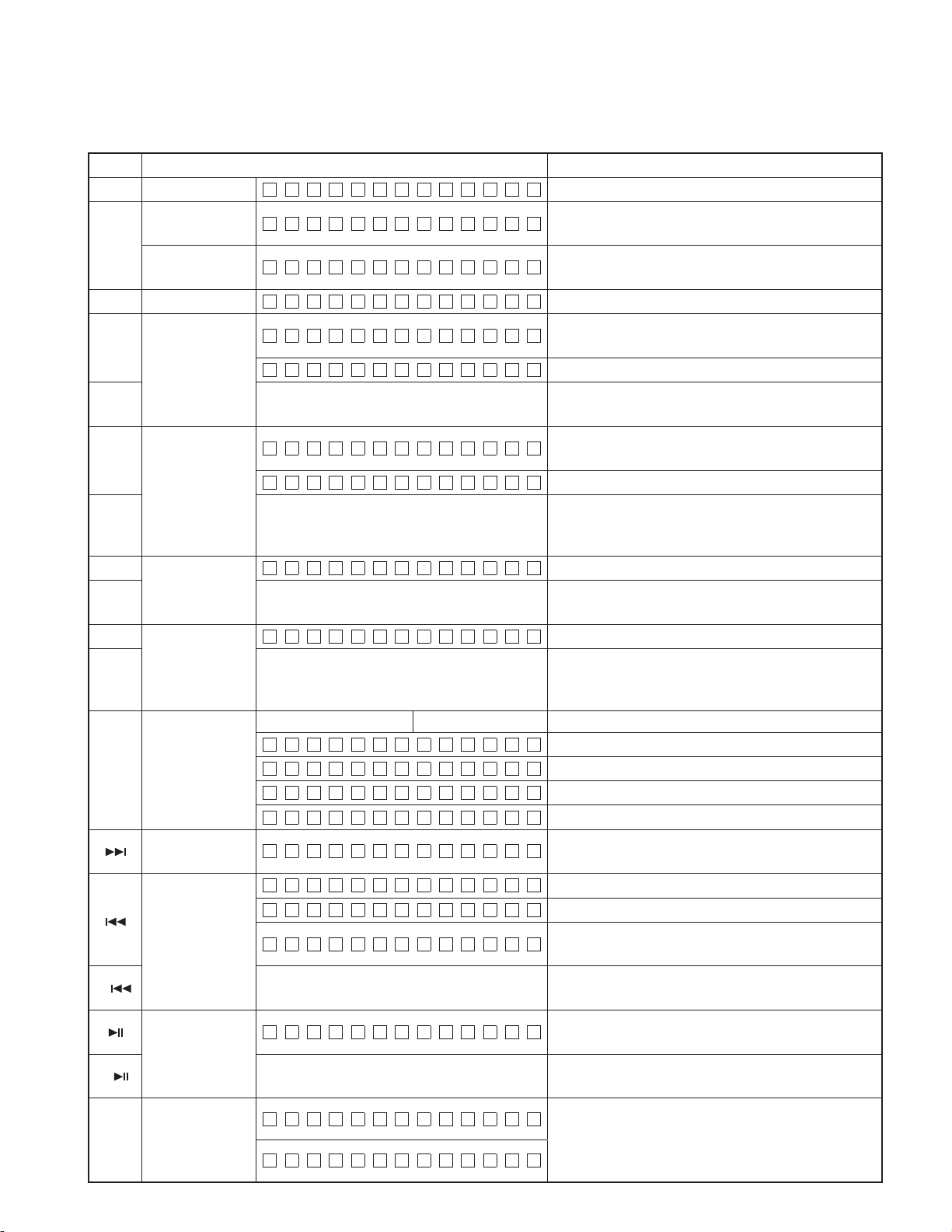
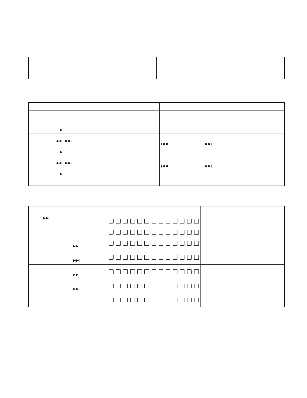
• Procedure in CD-DA media (KTD-02A)
Key Description of display Description
Track up procedure
Track down procedure Goes down by 1 track from the currently played track.
1 Jump procedure
2 Jump procedure Jump to No. 14 (Blurring surface disc TCD-731RA Tr14)
Information display
Mechanism model name
Mechanism version
Information display
Mechanism servo
3
version
Information display
Mechanism boot
program version
6 Jump procedure
6E20:
SERV:
BOOT:
Displays the data that has been written in the
E2PROM when pressing the key for 2 seconds or
longer.
Clear the FST adjustment mode. (Returns to
normal display and the test mode is retained.)
Every time pressed, jumps to the track shown below.
No.9 → No.15 → No.10 → No.11 → No.12 → No.13 →
No.22 → No.14 → No.9 (recursive)
But in case the disc has 8 tracks or less, playback starts
with track No.1. (For both CD-DA and compressed fi le
discs)
Jump to No. 28 (Scratch 0.7mm for MUSIC line vibration
testing)
Display of Mechanism model name and Mechanism
version. (When key is pressed while the display in the
left is being shown, returns to servo version display.)
Display of Mechanism model name and Mechanism
version. (When key is pressed while the display in the
left is being shown, returns to mechanism boot program
version display.)
Display of Mechanism model name and Mechanism
version. (When key is pressed while the display in the
left is being shown, returns to normal display.)
Jump to No. 15. Set the volume value to “25”.
(For 20Hz 0dB DC protection false-operation FCT
checking)
• Procedure in CD-DA media (MP3/WMA/AAC)
Key Description of display Description
File type display (MP3)
File type display (WMA)
File type display (AAC)
MP 3
WM A
AAC
Display fi le format just before the start of fi le play
back.
12
KDC-MP408U/MP438U/X492/MP5039U/MP5539U/W5041UA/
W5041UG/W5141UAY/W5141UGY/W5541U/W5641UY
TEST MODE
Audio-related test mode
■
Procedure Note
Press the [AUD] key (main unit)
Press the [AUD] and [∗] keys (Remote control)
About audio adjustment items (include both Audio Function Mode and Audio Setup Mode)
Procedure Item Procedure Description
Fader [VOL] knob and [ / ] key Adjust to 3 steps of R15 ↔ 0 ↔ F15. (Default value: 0)
Balance [VOL] knob and [
Bass Level [VOL] knob and [
For item
forwarding
procedure,
press [AUD]
key and
[FM] key
Middle Level [VOL] knob and [
Treble Level [VOL] knob and [
HPF Front [VOL] knob and [
HPF Rear [VOL] knob and [
LPF Sub woofer [VOL] knob and [
LPF Subwoofer Phase [VOL] knob and [
Volume Offset [VOL] knob and [
Loudness [VOL] knob and [
Dual Zone [VOL] knob and [ / ] key Adjust to 2 steps of OFF ↔ ON . (Default value OFF)
Enter audio adjustment mode (the initial item should be Fader, and then, Balance
Bass Level → Middle Level → Treble Level → SW Level → System Q → HPF Front →
HPF Rear → LPF Sub Woofer). (Then after, any adjustment can be done.)
/ ] key Adjust to 3 steps of L15 ↔ 0 ↔ R15. (Default value: 0)
/ ] key Adjust to 3 steps of -8 ↔ 0 ↔ +8. (Default value 0)
/ ] key Adjust to 3 steps of -8 ↔ 0 ↔ +8. (Default value 0)
/ ] key Adjust to 3 steps of -8 ↔ 0 ↔ +8. (Default value 0)
/ ] key Adjust to 2 steps of Through ↔ 180Hz. (Default value: Through)
/ ] key Adjust to 2 steps of Through ↔ 180Hz. (Default value: Through)
/ ] key Adjust to 2 steps of 60Hz ↔ Through. (Default value: Through)
/ ] key Adjust to 2 steps of Normal ↔ Reverse. (Default value: Normal)
/ ] key Adjust to 2 steps of -8 ↔ 0 . (Default value 0)
/ ] key Adjust to 2 steps of OFF ↔ ON . (Default value OFF)
→
MENU-related test mode
■
Procedure Note
Press the [M.JOG] key (main unit)
Press the [DNPP/SBF] and [DIRECT] keys (Remote control)
Backup current measurement
■
Procedure Note
While ACC OFF (Back Up ON), Reset
PREOUT switching
■
Procedure Note
In the STANDBY source, press and hold [AUTO] key for
1 second or longer
Dual Zone switching
■
Procedure Note
In the except STANDBY source, press the [AUTO] key. Switches ZONE2 ON/OFF. (Default OFF)
Continuous forwarding by remote control is prohibited
MUTE terminal is OFF after 2 seconds, not after 15 seconds.
(During this time, the CD mechanism does not function.)
Switches PREOUT
13
KDC-MP408U/MP438U/X492/MP5039U/MP5539U/W5041UA/
W5041UG/W5141UAY/W5141UGY/W5541U/W5641UY
TEST MODE
Clearing CD mechanism information / Service information / DC offset error information (Clearing E2PROM data)
■
Status Display Description
While pressing and holding [2] key and
[5] key, reset-start.
While “– – – –” is displayed, power can be ON for 30 minutes. This mode is cancelled by resetting. (The last screen will not be retained.)
Data to be cleared is shown below.
CD mechanism error log display
Displays CD loading error data
CD mechanism information
Service Information
DC offset error information
Displays CD EJECT error data
Displays CD time code count error data (missing count)
Displays CD time code count error data (count not updated)
Power ON time display
CD operation time display
CD EJECT times display
PANEL open/close times display
Forced Power OFF information display
DC offset error 1 display (Provides information on whether there is an improper connection or another error)
DC offset error 2 display (Provides information on the number of capacitor leaks)
CD O
CD X
At normal termination
At abnormal termination
Clearing DC offset error detection data (E2PROM data clearing)
■
Procedure Note
While pressing and holding [3] key and [6] key, reset-start. Entering DC offset error display mode.
Procedure Display Description
Press and hold
the [3] and
[6] keys, and
reset-start
1
1
■
2
2
■
This mode is cancelled by resetting. (The last screen will not be retained.)
FM/AM channel space switching (KDC-MPxxxx and KDC-X492 only)
■
While Power OFF, press and hold [1] key and [5] key,
and press [SRC] key to Power ON
DC ER R
DC OK
DC1 ERR
DC1 OK
DC1 OK
DC2 4
DC2 0
Procedure Note
When DC offset error is detected (when either one of capacitors is
leaking, or an improper connection or another error is detected)
When DC offset error is not detected (when none of capacitors leak,
no improper connection or other error is detected)
When improper connection or other DC offset errors are detected.
When improper connection or other DC offset errors are not detected.
When detecting improper connection or other DC offset errors, clears
detection data. (Clear E2PROM)
When detecting capacitor leak, provides information on the number of
capacitor leaks. (0~4)
When detecting capacitor leak, clears the number of capacitor leaks.
(Clear E2PROM)
FM200kHz/AM10kHz ↔ FM50kHz/AM9kHz
FM50kHz/AM10kHz ↔ FM200kHz/AM10kHz (KDC-MP408U)
14
KDC-MP408U/MP438U/X492/MP5039U/MP5539U/W5041UA/
W5041UG/W5141UAY/W5141UGY/W5541U/W5641UY
TEST MODE
Security
■
• Forced Power ON mode
Procedure Note
While pressing and holding [M.JOG] key and [4] key, reset-start.
• How to register the security code on the “Car Audio Passport” after replacement of the FRONT-END (A1)
with E2PROM (Models for destination “M” and “E”)
Procedure Description
While pressing and holding [1] key and [3] key, reset-start Enters the test mode
Press the [M.JOG] key Enters the MENU mode.
Press and hold [
[FM] / [AM] / [
Press and hold [ ] key for 3 seconds or longer “RE-ENTER” is displayed.
[FM] / [AM] / [
Press and hold [ ] key for 3 seconds or longer “APPROVED” is displayed.
Reset, momentary power down, ACC OFF, Power OFF, panel removed Cancels the test mode.
Note: The security code in this model cannot be all-clear.
] key for 1 second or longer Enters the security registration mode.
/ ] key
/ ] key
While “– – – –” is displayed, power can be turned ON for only 30
minutes. After 30 minutes, can only be recovered by resetting.
Inputs the code. FM: Number up / AM: Number down /
: Cursor to the left / : Cursor to the right
Inputs the code again. FM: Number up / AM: Number down /
: Cursor to the left / : Cursor to the right
• Method of clearing the programmable security code (Models for destination “K”)
Procedure Display Description
Press [
while pressing [AUTO] key
Press the remote control [5] key 2 times,
display “K”, and press [ ] key.
Press the remote control [2] key 3 times,
display “C”, and press [ ] key.
Press the remote control [2] key 1 time,
display “A”, and press [ ] key.
Press the remote control [7] key 2 times,
display “R”, and press [ ] key.
] key for 3 seconds or longer-
CODE ––––
CODE
CODE K
CODE KC
CODE KCA
CODE KCA R
APPROVED
Carry out the procedure while “– – – –” is
being displayed.
“– – – –” disappears.
Security cancelled. (If wrong character is
input, code request mode is displayed.)
15
 Loading...