


KENWOOD KDC-MP5028, KDC-W6031, KDC-W6031Y Service Manual
CD RECEIVER
This product uses Lead Free solder.
KDC-MP5028/MP528
/W6031/W6031Y
© 2005-2 PRINTED IN JAPAN
SERVICE MANUAL
KDC-MP5028
KDC-MP528
B53-0241-00 (N) 1553
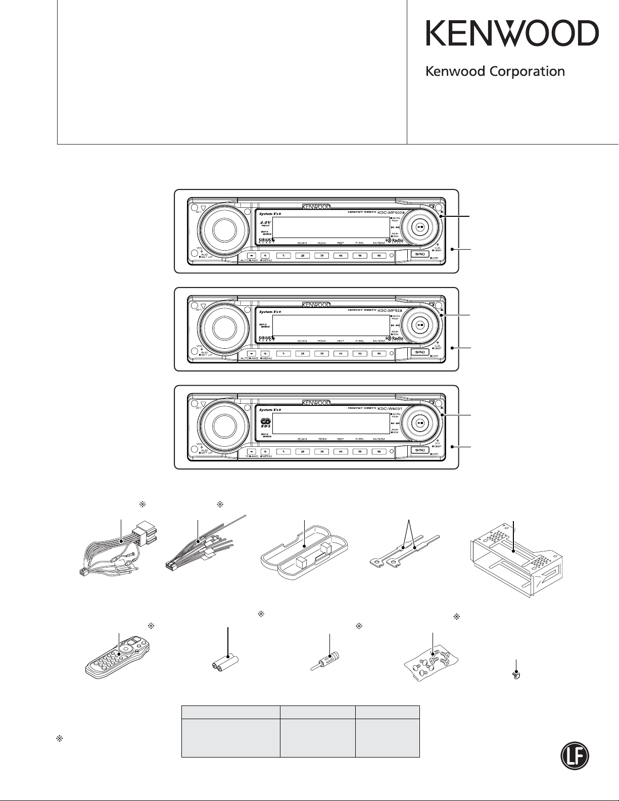
CD MECHANISM EXTENSION
CORD (24P) : W05-0934-00
Panel assy
(A64-3509-12)
Escutcheon
(B07-3125-01)
Panel assy
(A64-3510-12)
KDC-W6031
KDC-W6031Y
DC cord
(E30-6412-05)
Remote controller assy
(A70-2067-05)
DC cord
(E30-6414-05)
Size AA battery
(Not suplied)
Plastic cabinet assy
(A02-2732-03)
Antenna adaptor
(T90-0523-05)
Lever
(D10-4589-04)
Screw set
(N99-1723-05)
Escutcheon
(B07-3126-01)
Panel assy
(A64-3512-12)
Escutcheon
(B07-3126-01)
x2
Mounting hardware assy
(J21-9716-03)
Screw set
KDC-MP5028/MP528:
(N09-6212-05)
KDC-W6031/W6031Y:
(N09-6280-05)
RC-527
Depends on the model.
Refer to the parts list.
TDF PANEL INFORMATION
MODEL TDF PANEL No. TDF NAME
KDC-MP5028 Y33-2180-61 TDF-MP55DB
KDC-MP528 Y33-2180-62 TDF-MP55D
KDC-W6031/W6031Y Y33-2180-64 TDF-W6031
2
F/E
A8V
AM+B
SW5
RDS SW5
LX-BUS
BU
AUX
E-VOL
IC2
CD MECHA
SERVO+B
A8V
BU5V
CD5V
3.3VREF.
PRE+B
A8V
A8V
4VPRE-REF.
AM+B
IC9
IC11
Q300
A8V
AM+B
SYSTEM u-COM
OPELDISP
MARINEDISP
BU
PW-IC
PW-IC SVR
SP-OUT
MUTE
PRE-OUT
IC10
EEPROM
SW5
Q400-405
PRE-OUT(2V/4V)
IC902
3.3VREF.
SVR/
SVR+B
A8VPW-IC SVR
3.3VREF.
Q107
EXT-AMP
PHONE
ACC-DET
Q112
DIMMER
Q108
SURGE
Q109
PAN/
PANEL
Q7
BU5V
IC12
PCON-SW
Q1
Q103
BU-DET
Q111
4V
ILL+B
Q15
IC5
SVR+B
Q9
SW14V
Q4
SW5V
Q3
ANT-SW
Q101
CD SERVO
Q9
PAN
Q18
A8V
Q5
PAN5V
Q13
DC-CN
BU5PAN5V
ILL+B
A8V
PRE+B
SVR+B
SERVO+B
CD5V
BU5
SW5
P-M+B
ILL+B
M+B
PRE+B
CD5V
DET
TYPE-SW
OEM TYPE-SW
MUTE
BU5
BU5
DC-CN etc
GUIDE ILL
DSI/
BU5
EEP-DET
MECHA
SLIDE
DET
MOTOR
DRIVER
P-M+B
RST
IC7
IC8
BU5
PAN5
ILL+B
CN/FPC
MECHA
SLIDE
CN-DET
RESET
ENCODER
ROT ARY
REMO
SW5V
SW
SW
F+/F-
DISP BLACK
FL DRIVER
ILL
KEY-ILLUMI
SW ILLUMI
KEY
MATRIX
KEY
FL
IC2-6
IC1
MOTOR+B
SW5
Q1
IC1
Q6
PAN5
PAN5
Q2
F+/F-
FL+B
OUT SW
Q4,5
IC4
IC2
FST
DXM6580W
DXM6800W
3
8
2
8
2
4321043
5
R/R
R/L
F/R
F/L
2
FRONT
REAR
SUB-WOOFER
P ON
PON ILL
P ON
PON PAN CD
P ON
ANT CON P CON
BU
EXT-CONT
ACC
ILLUMI
PHONE
P-ANT
P-CON
B.U.
MUTE DC-DET
PON PAN
(PWR OFF ONLY)
DET
EXT CONT
PHONE
ACC DET
DIMMER
2
3
2
PW-IC
E-VOL
RST
BU DET
EXT CONT/PHONE
DIMMER/ACC DET
P CON/PON
BU DET/ANT CON
PON PAN CD/PON ILL
PON PAN
11
52
SW
FUNCTION
55
9
P ON
ELECTRIC UNIT (X34-342x-xx/3762-71)
(X16- )
KDC-MP5028/MP528
/W6031/W6031Y
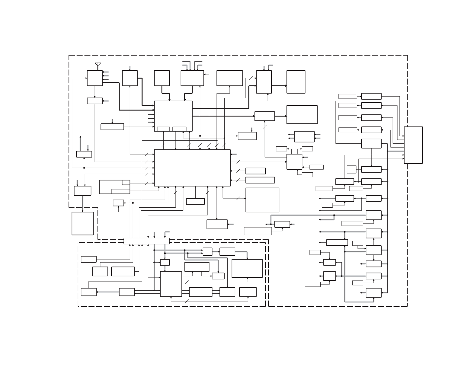
BLOCK DIAGRAM
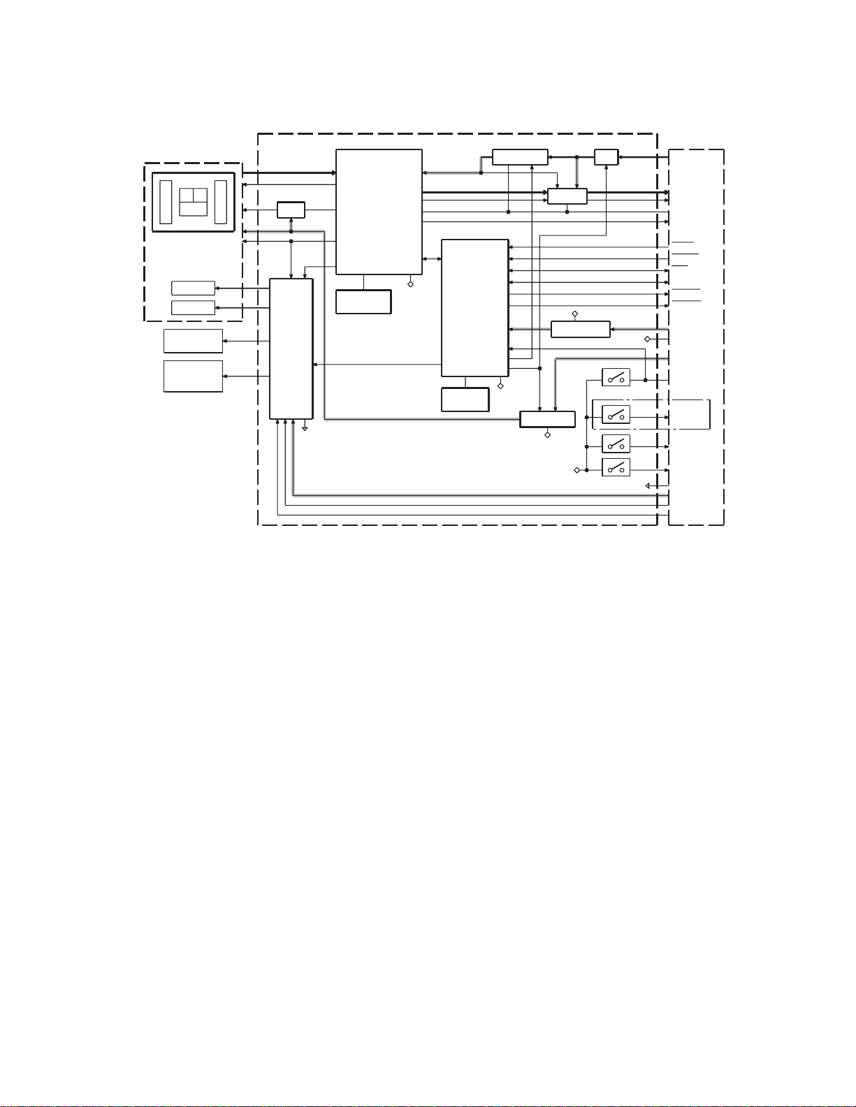
BLOCK DIAGRAM
KDC-MP5028/MP528
/W6031/W6031Y
PICKUP
ACB
EF
FO COIL
TR COIL
SPINDLE
MOTOR
LOADING &
SLED
MOTOR
CD PLAYER UNIT (X32-5740)
IC7
RF AMP
+
SERVO
PROCESSOR
+
MP3 DECODER
APC
IC3
MOTOR
DRIVER
S.GND
+
WMA DECODER
+
AAC DECODER
+
1Mbit SRAM
VREF
CLOCK
16.934MHz
D.GND
DMUTE
IC4
MICRO
PROCESSOR
P-ON2
P-ON1
CLOCK
16.00MHz
IC1
A3.3V REG
D.GND
IC6
IC2
LPF
IC5
BU3.3V REG
D3.3V REG
D.GND
D.GND
SW
D.GND
(0-01)ONLY
D.GND
S3
S4
S2
S1
S.GND
MOTHER
BOARD
A8V
L-ch
R-ch
A.GND
D.OUT
MRST
MSTOP
CLK
DATA
MUTE L
MUTE R
BU5V
D.GND
D5.0V
LOE/LIM-SW
8EJE-SW
12EJE-SW
LOS-SW
S.GND
S7.5V
LO/EJ
MOTOR
3
KDC-MP5028/MP528
/W6031/W6031Y
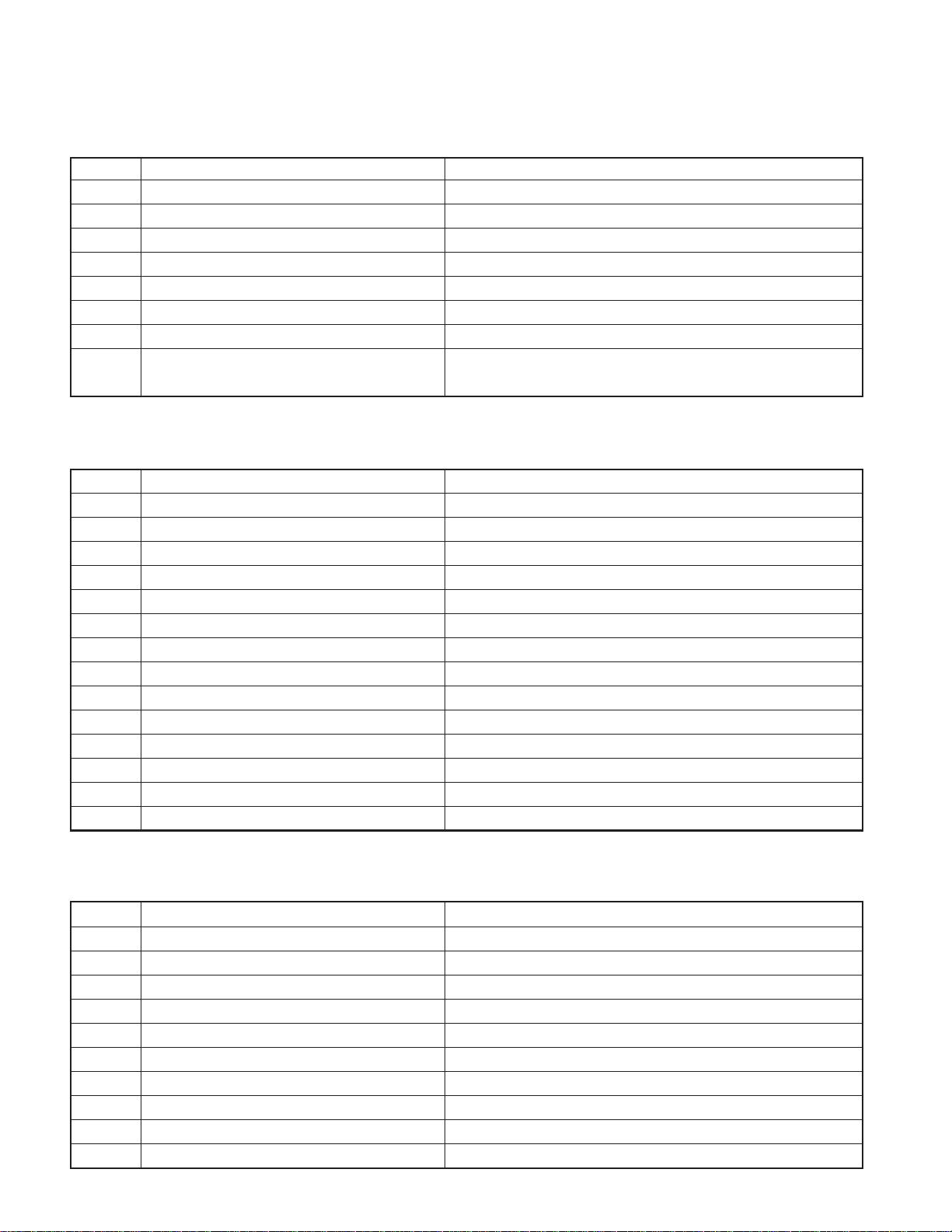
COMPONENTS DESCRIPTION
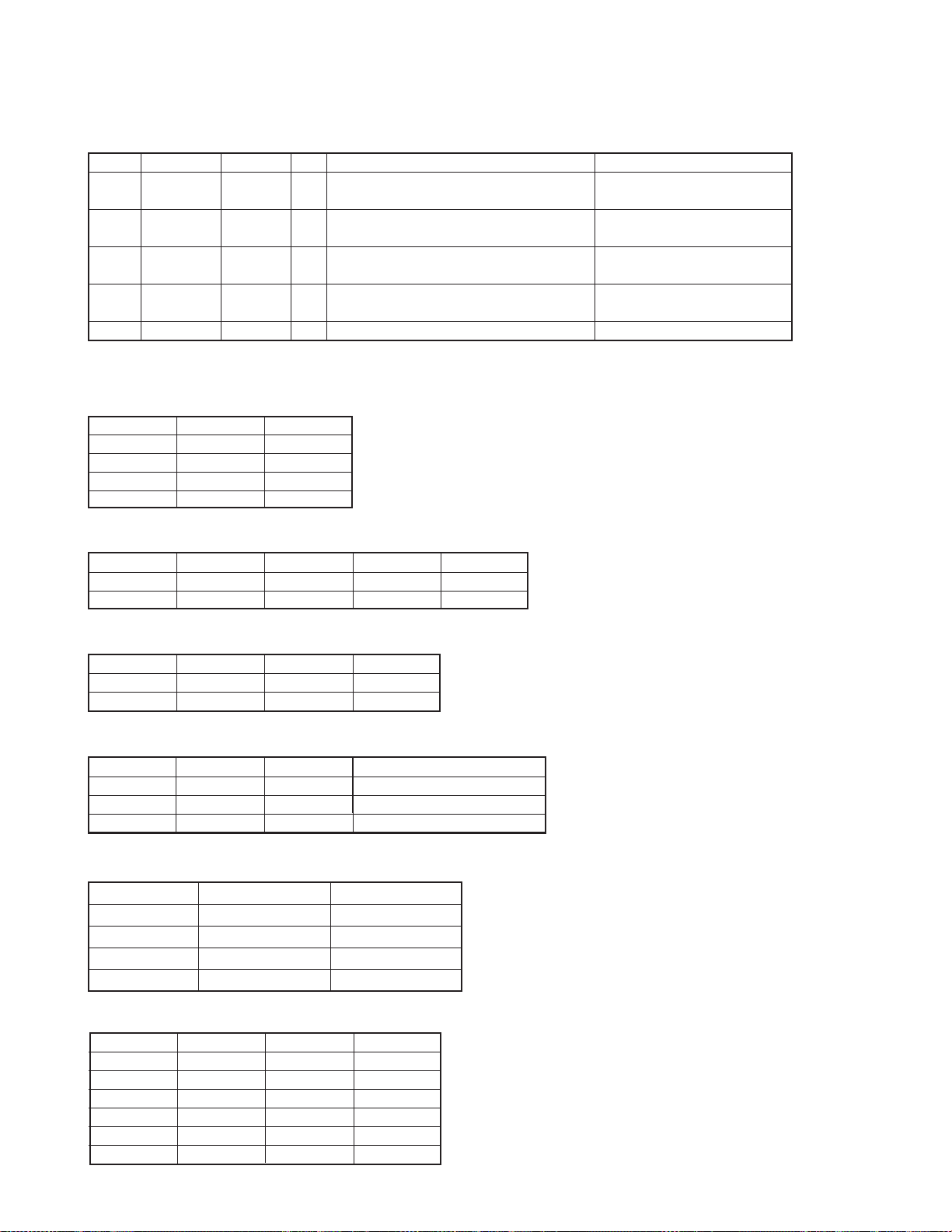
● SWITCH UNIT (X16-2920-11/3142-70)
Ref. No. Application / Function Operation / Condition / Compatibility
IC1 VFD Driver
IC2 Remote Control IC
Q1 SW5 The power supply for IC2 is turned on when Q1’s base level goes “L”.
Q2,Q3 FL+ SW
Q4 GREEN LED SW GREEN LED is turned on when Q4’s base level goes “H”.
Q5 RED LED SW RED LED is turned on when Q5’s base level goes “H”.
Q6,Q7 VFL SW
Q8
GREEN LED SW
(TRIANGLE LED)
● CD PLAYER UNIT (X32-5740-0x)
Ref. No. Application / Function Operation / Condition / Compatibility
IC1 A3.3V regulator Power supply for audio 3.3V
IC2 Ope amp for low-pass filter
IC3 4ch BTL driver Driving spindle motor and loading/ejection operation
IC4 µ-com
IC5 Bu 3.3V regulator Power supply for backup 3.3V
IC6 D3.3V regulator Digital 3.3V power supply
IC7 Audio DAC built-in servo DSP MP3, WMA, and AAC compatible
IC8 Memory IC Used only for 0-02 destination
IC11 Buffer IC Level sh ift
Q1 A3.3V discharge circuit
Q4 Electric AMP Adjusts current to be sent to laser
Q5,6 SW 5V
Q7,8 SW 8V
D1 For electric AMP
The power supply for filament is turned on when Q3’s base level goes “H”.
The power supply for IC1’s VFL is turned on when Q7’s base level goes “H”.
GREEN LED (TRIANGLE LED) is turned on when Q8’s base level goes “H”.
● ELECTRIC UNIT (X34-342x-xx/3762-71)
Ref. No. Application / Function Operation / Condition / Compatibility
IC1 System µ-com
IC2 E-vol IC
IC3 Regulator IC for A8V
IC4 Power IC
IC5 Regulator IC for ILL+B (10.65V)
IC6 Logic IC for muting
IC7 Reset IC
IC8 Motor Driver IC for Slide panel mecha
IC9 RDS Decoder IC
IC10 Rom IC for Installer-Memory and Rom-Correction
4
KDC-MP5028/MP528
/W6031/W6031Y
COMPONENTS DESCRIPTION
Ref. No. Application / Function Operation / Condition / Compatibility
IC11 AMP for 4V Pre-Out Ref.
IC12
IC902 AMP for Power IC SVR and E-vol IC 3.3V Ref.
Q1,2 B.U.5V AVR While BU is applied, BU5V AVR outputs 5V.
Q3,11 SW5V When Q11’base goes Hi, SW5V outputs 5V.
Q4,906 SW14V When Q4’base goes Hi, SW14V outputs 14V.
Q5,6 AUDIO8V AVR When Q6’base goes Hi, A8V AVR outputs 8.3V.
Q7,8 MOTOR+B AVR When Q8’base goes Hi, M+B AVR outputs 8.3V.
Q9,10 SERVO+B AVR When Q10’base goes Hi, S+B AVR outputs 7.7V.
Q12 SW for IC12 When Q12’base goes Lo, IC12 is turned on.
Q13 PAN5V When Q13’base goes Lo, PAN5V outputs 5V.
Q14 4V PRE+B Short Protection
Q15,16 4V PRE+B When Q15’base goes Hi, 4V PRE+B outputs 12V.
Q17,18 ILL+B SW When Q17’base goes Hi, ILL+B SW outputs 10.65V.
Q101,102 P-ANT SW When Q102’base goes Hi, P-ANT SW outputs 14V.
Q103,106 P-CON SW When Q106’base goes Hi, P-CON SW outputs 14V.
Q104,105 P-CON Protection
Q107 Ext Amp Control Buffer
Q108 Small lamp det SW When Q108’base goes Hi, Q108 is turned on.
Q109,110 Surge det When Q109’base goes Hi, Q109, Q110 are turned on.
Q111 BU det When Q111’base goes Hi, Q111 is turned on.
Q112 ACC det When Q112’base goes Hi, Q112 is turned on.
Q113 Mute driver When Q113’base goes Lo, mute driver is turned on.
Q114 Mute driver When Q114’base goes Lo, mute driver is turned on.
Q115,116 Mute driver When a base goes Lo, mute driver is turned on.
Q300,301 AM+B SW When Q301’base goes Hi, AM+B is out.
Q304 DSI (Disabled System Indicator) DSI blinks when Q304’base goes “H/L”
Q400~405 Pre-out mute SW When a base goes Hi, Pre-out is muted.
Q905 SVR+B AVR When Q905’base goes Hi, SVR+B AVR outputs 14V.
Switching regulator IC for CD mecha D5V and FL filament
If Q15’Emitter short to GND, between Q14’Base to Emitter more than
0.6V, Q14 ON and Q15 is turned off.
Protects Q104 from being triggered erroneously. This is achieved by
turning on output protection when P-CON output grounding is detected.
5
KDC-MP5028/MP528
/W6031/W6031Y
MICROCOMPUTER’S TERMINAL DESCRIPTION
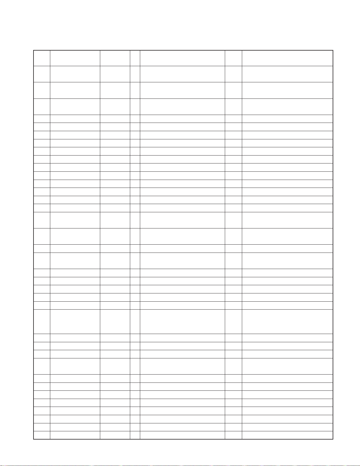
● MECHANISM MICROCOMPUTER 703030BYGCJ09A (X32-574 : IC4)
Pin No. Pin Name I/O Application
1NCONot used. Low-fixed
2 E2P_SCL I/O Rom correction E2P I2C clock
3~5 NC O Not used. Low-fixed
6 VDD - 5V electric potential
7 GND - GND electric potential
8,9 NC O Not used. Low-fixed
10,11 PON1,PON2 O Power ON/OFF control H : ON, L : OFF
12 LOE/LIM_SW I Down-limit SW detection L : Lim detection
13 DAC_MUTE O DAC MUTE control H : MUTE ON, L : MUTE OFF
14 DAC_RST O DAC RESET H : NORMAL, L : RESET
15 EMPH O External DAC Emphasis control
16,17 NC O Not used. Low-fixed
18 IC/Vpp - Write voltage (FLASH)
19 MUTE_L O Lch audio MUTE control L : MUTE ON, H : MUTE OFF
20 MUTE_R O Rch audio MUTE control L : MUTE ON, H : MUTE OFF
21 TYPE I DAC switching terminal
22 TEST_O 1 O TEST MODE O 1 (Not used.)
23 TEST_O 2 O TEST MODE O 2 (Not used.)
24 TEST_O 3 O TEST MODE O 3 (Not used.)
25 TEST_O 4 O TEST MODE O 4 (Not used.)
26 NC O Not used. Low-fixed
27 WAIT I Wait control signal detection
28~30 NC O Not used. Low-fixed
31 RESET I Reset detection H : NORMAL, L : RESET
32 XT1 I Not used.
33 XT2 - Not used.
34 REGC 35 X2 36 X1 I
37 Vss - GND electric potential
38 VDD - 5V electric potential
39 NC O NC Output stopped in standby 3.3V driven
40 WRL I Multiplex WRITE signal 3.3V driven
41,42 NC O Not used. Low-fixed 3.3V driven
Processing Operation
Description
H : Emphasis ON, Used only with DXM-6590W.
L : Emphasis OFF With DXM-6580W, open and L-fixed.
L : Normal operation,
H : In writing.
H : DSP built-in DAC used,
L : DSP built-in DAC Not used.
* DXM-6580W : X92-5080-00, DXM-6590W : X92-5190-00
Remarks
Used only with DXM-6590W.
With DXM-6580W, open and L-fixed.
Used only with DXM-6590W.
With DXM-6580W, open and L-fixed.
H : DXM-6580W, L : DXM-6590W
6
KDC-MP5028/MP528
/W6031/W6031Y
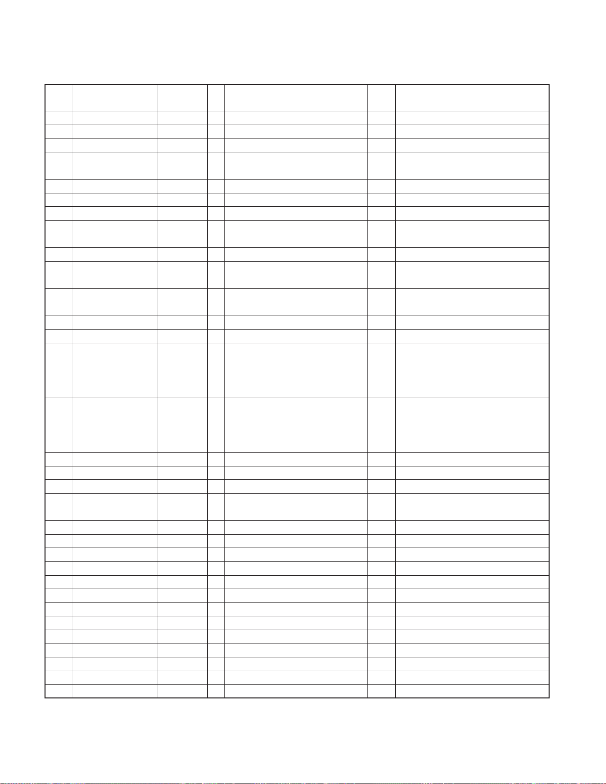
MICROCOMPUTER’S TERMINAL DESCRIPTION
Pin No. Pin Name I/O Application
43 RD O Multiplex RD signal 3.3V driven
44 ASTB O Multiplex ASTB signal 3.3V driven
45 NC O Not used. Low-fixed 3.3V driven
46 NC O Not used. Low-fixed 3.3V driven
47~54 AD0~AD7 I/O Multiplex address/data 3.3V driven
55 BVdd - Bus interface power supply
56 BVss - Bus interface GND
57~61 AB8~AB12 I/O Multiplex data/address 3.3V driven
62~65 NC O Not used. Low-fixed 3.3V driven
66 CS O Chip select control H : OFF, L : ON 3.3V driven
67 DSP RESET O DSP reset control H : NORMAL, L : RESET 3.3V driven
68~70 NC O Not used. Low-fixed 3.3V driven
71 Avdd 72 Avss 73 Avref I A/D port reference voltage input
74 NC I Not used. Low-fixed
75 RAMSEL I
76 RZM I 0bit MUTE detection H : ≥1.7V, L : <1.7V
77 LZM I 0bit MUTE detection H : ≥1.7V, L : <1.7V
78 AAC I AAC compatibility switching
79 ASEL I Audio output polarity switching
80 E2P_WR I E2PROM write switching
81 TEST_I 0 I TEST MODE I 0 (Not used.)
82 TEST_I 1 I TEST MODE I 1 (Not used.)
83 TEST_I 2 I TEST MODE I 2 (Not used.)
84 TEST_I 3 I TEST MODE I 3 (Not used.)
85 NC I Not used. Low-fixed
86 NC O Not used. Low-fixed
87 MSTOP I Standby restart interruption H : STOP release, L : STOP
88 INTSV I Interruption from servo IC H : Interruption
89~92 NC O Not used. Low-fixed
93 D-MUTE O Driver MUTE H : OFF, L : ON
94 SYS_SDA I/O System µ-com I2C data Flash write port (SI0)
95 NC O Not used. Low-fixed Flash write port (SO0)
96 SYS_SCL I/O System µ-com I2C clock Flash write port (SCK0)
97~99 NC O Not used. Low-fixed
100 E2P_SDA I/O ROM correction E2P I2C data
With DRAM/No DRAM switching
for different models
Processing Operation
Description
H : With DRAM, L : No DRAM
H : AAC non-compatible, AAC non-compatible mode has priority
L : AAC compatible for both hardware and software.
H : Reverse output,
L : Non-reverse output
H : E2PROM WRITE,
L : NORMAL
Remarks
7
KDC-MP5028/MP528
/W6031/W6031Y
MICROCOMPUTER’S TERMINAL DESCRIPTION
● MAIN MICROCOMPUTER 30624MWPA35GP (X34 : IC1)
Pin No.
1 REMO EXTRA I Remote controller signal input Pulse width is detected.
2 LX_MUTE LX_M I Mute request from slave unit H : Mute ON, L : Mute OFF
3AUD_SDA AUDIO I/O E-VOL data output terminal
4AUD_SEL AUDIO O E-VOL control terminal
5AUD_SCL AUDIO O E-VOL clock output terminal
6 BYTE µCOM 7 CNVSS µCOM 8 XCIN µCOM I
9 XCOUT µCOM I
10 RESET µCOM 11 XOUT µCOM 12 VSS µCOM 13 XIN µCOM - 12.0MHz
14 VCC1 µCOM 15 NMI µCOM I Not used.
16 CN_DET EXTRA I Panel communication detection H : No PANEL, L : With PANEL
17 RDS_CLK TUNER I
17 NC O Not used. (Other than RDS Model) Output L-fixed
18 LX_REQ_S LX_M I Communication request from slave unit
19 PON_AM Power supply I/O AM power supply control
20 LX_REQ_M LX_M O Communication request to slave unit
21 TUN_IFC_OUT TUNER I F/E IFC OUT input terminal H : With station, L : No station
22 RDS_AFS_L TUNER I/O Constant switching at noise detection r Refer to truth value table.
23 RDS_AFS_M TUNER I/O Constant switching at noise detection r Refer to truth value table.
24 RDS_QUAL TUNER I
24 NC O Not used. (Other than RDS Model) Output L-fixed
25 RDS_DATA TUNER I
25 NC O Not used. (Other than RDS Model) Output L-fixed
26 PWIC_BEEP PWIC O Beep output
27 TUN_SCL TUNER I/O F/E I2C clock input/output terminal (MAX400kHz)
28 TUN_SDA TUNER I/O F/E I2C data input/output terminal
29 VFD_SYS_DATA toPANEL O VFD data output terminal Data output
30 VFD_PAN_DATA toPANEL I VFD data input terminal Data input
31 VFD_CL toPANEL O VFD clock output terminal 125kHz
32 VFD_INH toPANEL O VFD data blanking output H : Light ON, L : Light OFF
33 SDA/CD_SDA CD I/O
33 SDA/ROMCOR_SDA EXTRA I/O
34 SCL/CD_SCL CD I/O
Pin Name
Module
(functional)
I/O Application
RDS decoder CLK input terminal
(RDS Model only)
RDS decoder QUAL input terminal
(RDS Model only)
RDS decoder DATA input terminal
(RDS Model only)
CD mechanism I2C data input/output
terminal
ROM correction E2PROM I2C data
input/output terminal
CD mechanism I2C clock output
terminal
Truth
Value Table
Processing Operation Description
AM in operation : H,
AM not in operation : Hi-z
8
KDC-MP5028/MP528
/W6031/W6031Y
MICROCOMPUTER’S TERMINAL DESCRIPTION
Pin No.
34 SCL/ROMCOR_SCL EXTRA I/O
35 PON_PANEL Power supply I/O Panel 5V control terminal
36 DSI EXTRA I/O DSI control terminal
37 PM_MOT1 P-MECHA O Panel motor control 1 w Refer to truth value table.
38 PM_MOT2 P-MECHA O Panel motor control 2 w Refer to truth value table.
39 ELM µCOM I FLASH EPM input terminal
40 PM_OPEN P-MECHA I P anel full open detection e Refer to truth value table.
41 PM_CLOSE P-MECHA I Panel mechanism close detection e Refer to truth value table.
42 ROMCOR_DET EXTRA I E2PROM write request H : Writing
43 PM_DET P-MECHA I Panel mechanism detection H : Function check in progress
44 VFD_CE toPANEL O VFD_control request
45 ROTARY_CW toPANEL I VOL key input Pulse width is detected.
46 ROTARY_CCW toPANEL I VOL key input Pulse width is detected.
47 CD_DISC12_SW CD I CD disc detection terminal (12cm)
48 CD_LOS_SW CD I CD loading detection terminal
49 CD_MUTE_R CD I CD MUTE(Rch) request terminal
50 CD_MUTE_L CD I CD MUTE(Lch) request terminal
51 CD_MRST CD O CD mechanism µ-com RST terminal H : Normal, L : Reset
52 CD_MSTOP CD O CD mechanism µ-com stop terminal
53 NC CD O Not used. Output L-fixed
54 CD_LOE_LIM_SW CD I CD detection terminal (Chucking SW) H : Loading complete, L : No disc
55 CD_LOEJ CD I/O CD motor control terminal q Refer to truth value table.
56 CD_MOTOR CD O CD motor control terminal q Refer to truth value table.
57 PON_ILLUMI Pow er supply I/O Key Illumi power supply control ON : H, OFF : Hi-Z
58 PON_PANEL_CD Power supply O
59 PON Power supply O Power supply control POWER ON : H, POWER OFF : L
60 VCC2 µCOM 61 EXT_AMP_CON EXTRA I/O External AMP control
61 NC O
62 VSS µCOM 63~65 TYPE_1~TYPE_3 TYPE I Destination switching y Refer to truth value table.
66 TUN_TYPE1 TYPE I Destination setting 1 t Refer to truth value table.
67 TUN_TYPE2 TYPE I Destination setting 2 t Refer to truth value table.
68 OEM_DISP_DATA EXTRA I/O External display data External display
68 NC O Not used. (M-destination only) Output L-fixed
69 OEM_DISP_CLK EXTRA I/O External display CLK External display
69 NC O Not used. (M-destination only) Output L-fixed
Pin Name
Module
(functional)
I/O Application
ROM correction E2PROM I2C clock
output terminal
Panel 5V/CD WMA Power supply
control terminal
Not used. (Destination with no external
AMP control)
Truth
Value Table
Processing Operation Description
POWER ON : Hi-Z, POWER OFF : L,
50Ms before PON_PANEL/CD turns H : L
OFF : Hi-z No PANEL : Pulse driven
ILL_ON, OPEN (When Power_ON) : H
H : Normal, L : Rch mute request
Effective only for CD
H : Normal, L : Lch mute request
Effective only for CD
H : CD mechanism µ-com in operation
L : CD mechanism µ-com stop
POWER ON : L POWER OFF : H, when
RESET, L before M-STOP. Refer to timing
chart
Output L-fixed
9
KDC-MP5028/MP528
/W6031/W6031Y
MICROCOMPUTER’S TERMINAL DESCRIPTION
Pin No.
70 OEM_DISP_CE EXTRA I/O External display control request External display
70 NC O Not used. (M-destination only) Output L-fixed
71 NC EXTRA O Not used. Output L-fixed
72 P_CON Power supply O External AMP control terminal
73 KEY_REQ toPANEL I
74 ANT_CON EXTRA O Power antenna control TUNER ON : H
75 ILLUMI_DET EXTRA I Dimmer Illumi control L : ON, H : OFF
76 BU_DET EXTRA I Momentary power down detection
77 ACC_DET EXTRA I ACC Power supply detection With ACC : L, No ACC : H
78 (PWIC_SVR) PWIC O SVR discharge circuit
79 PWIC_MUTE PWIC O Power IC MUTE terminal
80 PWIC_STBY PWIC O Power IC standby control POWER ON : H, POWER OFF : L
81 LX_CON LX_M O Boot up request to slave unit H : Slave unit ON, L : Slave unit OFF
82 MUTE_PRE_R AUDIO O PRE_OUT MUTE Rch
83 MUTE_PRE_L AUDIO O PRE_OUT MUTE Lch
84 MUTE_0 AUDIO I/O E-VOL FRONT MUTE terminal L : MUTE ON, Hi-Z : MUTE OFF
85 MUTE_1 AUDIO I/O E-VOL REAR MUTE terminal L : MUTE ON, Hi-Z : MUTE OFF
86 MUTE_2 AUDIO I/O E-VOL OTHER MUTE terminal L : MUTE ON, Hi-Z : MUTE OFF
87 LINE_MUTE EXTRA I Line mute detection
88 NC O Not used. Output L-fixed
89 PWIC_DC_DET PWIC I DC Offset detection terminal
90 LX_RST LX_M O Hard resetting to slave unit H : Reset, L : Normal
91 MUTE_C AUDIO I/O E-VOL MUTE terminal (For AFS) L : MUTE ON, Hi-Z : MUTE OFF
92 NC O Not used. Output L-fixed
93 RDS_NOISE TUNER I FM noise detection terminal
94 AVSS µCOM 95 TUN_SMETER TUNER I S-meter output
96 VREF µCOM - Connect to P_ON
97 AVCC µCOM - Connect to VCC
98 LX_DATA_S LX_M I Data from slave unit
99 LX_DATA_M LX_M I/O Data to slave unit
100 LX_CLK LX_M I/O LX BUS clock
Pin Name
Module
(functional)
I/O Application
Communication request from VFD driver
Truth
Value Table
Processing Operation Description
POWER ON : H, POWER OFF : L,
STANDBY source : L
Connect to VFD_PAN_DATA
With BU : L,
No BU, Momentary power down : H
When POWER OFF and momentary
power down, for 5 sec. : H, Then, : L
When STANDBY source and momentary
power down : L, When TEL MUTE : L
When CD MUTE R is L : H (When CD)
At momentary power down : H
Refer to timing chart. Only with 2-zone
and NAVI interruption : L-fixed
When CD MUTE L is L : H (When CD)
At momentary power down : H
Only with 2-zone and
NAVI interruption : L-fixed
TEL MUTE : 1V or less
NAVI MUTE : 2.5V or more
10
KDC-MP5028/MP528
/W6031/W6031Y
MICROCOMPUTER’S TERMINAL DESCRIPTION
PANEL General Purpose Port Functional Allocation
Pin No. Active (H/L) Pin Name I/O Application Processing Operation Description
68 H RED O RED LED control terminal
69 H GREEN O GREEN LED control terminal
70 L PON O Panel SW5V control terminal
71 H DBO O Triangle LED control terminal (eXcelon only)
71 NC O Not used. (Other than eXcelon) Output L-fixed
Truth V alue T able
q CD_MOTOR, CD_LOEJ
CD_MOTOR CD_LOEJ
Stop L L
Load H L
Eject H H
Brake H Hi-z
RED : H
GREEN : L
RED : L
GREEN : H
SW5V ON : L
SW5V OFF : H
DISPLAY BLACKOUT ON : H
DISPLAY BLACKOUT OFF : L
w PANEL MOTOR CONTROL
OPEN CLOSE STOP WAIT
PM_MOT1 L H H L
PM_MOT2 H L H L
e PANEL MECHANISM CONTROL
FULL_OPEN FULL_CLOSE OTHER
PM_OPEN H L L
PM_CLOSE H L H
r AFS CONTROL
RDS_AFS_M RDS_AFS_L Condition
AFS LOW L L No sound output with AF search
AFS MID L Hi-Z Sound output with AF search
AFS HIGH Hi-Z Hi-Z Normal reception
t TUNER TYPE
TUN_TYPE1 (66PIN) TUN_TYPE2 (67PIN)
Third party model L L
OEM Model 1 L H
OEM Model 2 H L
OEM Model 3 H H
y Destination
TYPE3 TYPE2 TYPE1 Destination
000KDC-X589
001KDC-MP5028
010KDC-MP528
011KDC-W6531
100KDC-W6031
101KDC-X7529
11
KDC-MP5028/MP528
/W6031/W6031Y
TEST MODE
●How to enter the test mode
In order to enter the test mode, reset the unit while simultaneously pressing down [1] and [3] keys.
●How to clear the test mode
The test mode is cleared in case of any of the following e v ents:
resetting, momentary power down, Acc OFF, P ower OFF and
removal of the panel.
●Initial conditions of the test mode
• Source is STANDBY.
• Displays lights are all turned on.
• The volume is at -10dB (The display is 30).
• Loudness (LOUD) is OFF.
• CRSC is OFF, regardless of whether there are switching
functions or not.
• SYSTEM Q is NATURAL (=FLAT).
• BEEP will sound anytime with a short push.
•Auxiliary (AUX) is ON.
• SWPRE is SUB WOOFER (2 PREOUT models).
●RDS automatic measurement
Conventionally, the PS display has been visually checked on
the production line. This will be replaced by a new processing.
The PS data will be received and the PS contents is to be
verified as “RDS_TEST” When this is verified, the P-CON terminal is forced to go OFF. ( In this case, “_” means blank. )
→This will be a dedicated test mode processing.
On the P-CON, when power is turned off once and, then,
turned on again, (Power OFF → ON ) the unit will be
restarted.
•AUTO : FM1_98.1A
•Forced WIDE : FM1_98.1W
•Forced MIDDLE : FM1_98.1M
•Forced NARROW : FM1_98.1N
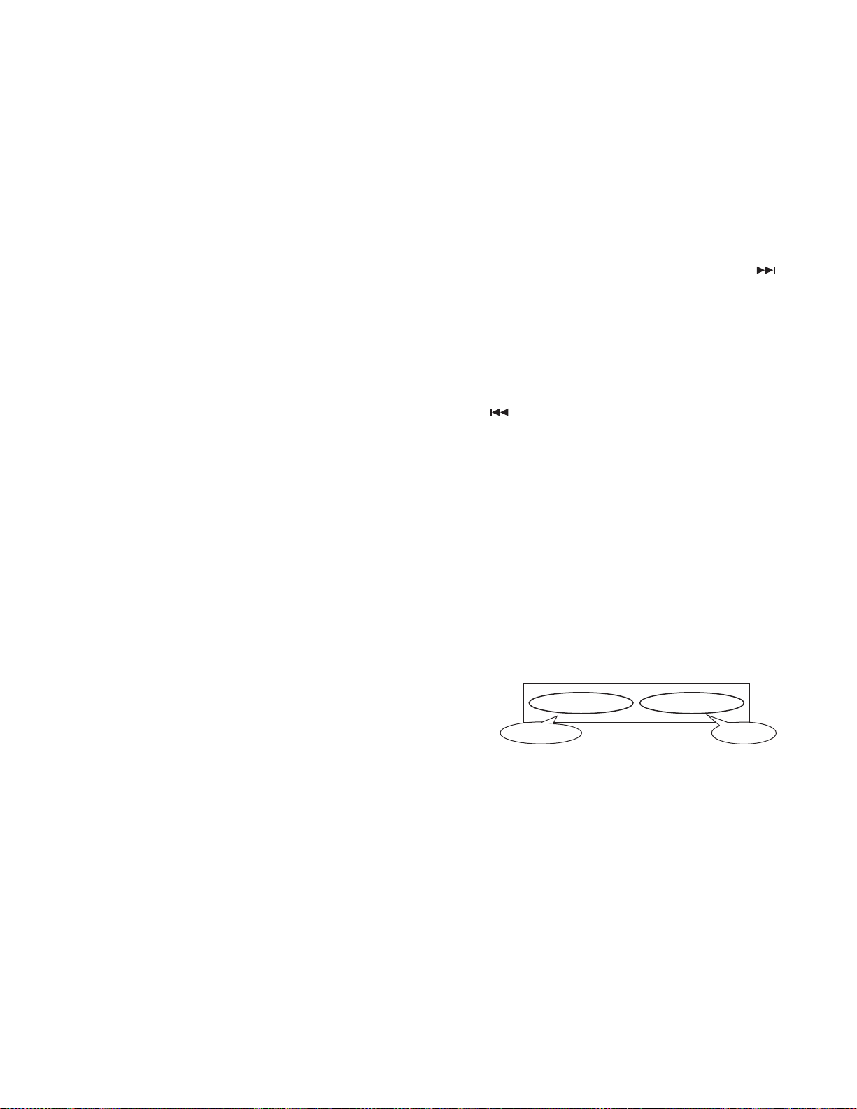
●CD receiver test mode specifications
•In the display mode, the initial setting is P-TIME.
•Jumps are made to the following trac ks b y pressing the
key .
No.9 → No.15 → No.10 → No.11 → No.12 → No.13 →
No.22 → No.14 → No.9 (Returns to the beginning)
It must be noted, however, that when paying MP3 / WMA /
AAC disk, which contain 8 files or less, the first track and
the following tracks are played in order.
• When
•When playing MP3 / WMA / AAC disks, the file format is
displayed immediately before playing each file.
(“MP3”, “WMA”, “AAC”)
• When a CD is used as a source, by short-pressing [1] key, a
jump to the Track No.28 is made.
• When a CD is used as a source, by short-pressing [2] key, a
jump to the Track No.14 is made.
• When a CD is used as a source, by short-pressing [3] key, a
display of CD mechanism model name and its version is
made. When the short-pressing of [3] key is made for the
second time, the normal display is resumed. (Time code
display)
key is pressed, it goes down b y one track.
Display
contents
Model Name
6 8 0 0
:
0 1 2 3
Version
●Special display when set to TUNER
When in TUNER mode, if an y of the f ollowing displa ys appear,
there is an abnormality with the front end.
• “TNE2P_NG” : The E2PROM is still with the default (unspecified) value, due to the fact that the front-end being
shipped without going through the adjustment process.
• “TNCON_NG” : In this condition, the communication with
the front end is not possible.
●Forced switching of K3I
In TUNER FM mode, each time [6] key is pressed, the functions move in the following cycle : AUTO → forced WIDE →
forced MIDDLE → force NARROW → AUTO. The initial condition is AUTO and the displays below will appear.
12
• When a CD is used as a source, by short-pressing [6] key, a
jump to the Track No.15 is made. At the same time, the volume value is set to 25 (2V PRE) and 27 (4V PRE).
●Audio Adjust mode
• By short-pressing [AUD] key, the Audio Adjust mode is entered.
• As with the [AUD] key, [*] key on the remote controller can
be used to enter the Audio Adjust mode.
• As for the adjustment items, items for both the A UDIO FUNCTION MODE and SETUP MODE are included.
• The first item is the Fader which is follo w ed b y : Balance →
Bass Level → Middle Level → Treble Level → ( Sub W oofer
Level ) → HPF Front → HPF Rear → LPF Sub W oofer. (Af-