

CD RECEIVER
KDC-MP4036U/MP435U/X491
KDC-W4537UA/W4537UAY
KDC-W4537UG/W4537UGY
KDC-W4737U/W4737UY
SERVICE MANUAL
© 2007-4 PRINTED IN JA PA N
B53-0513-00 (N) 552
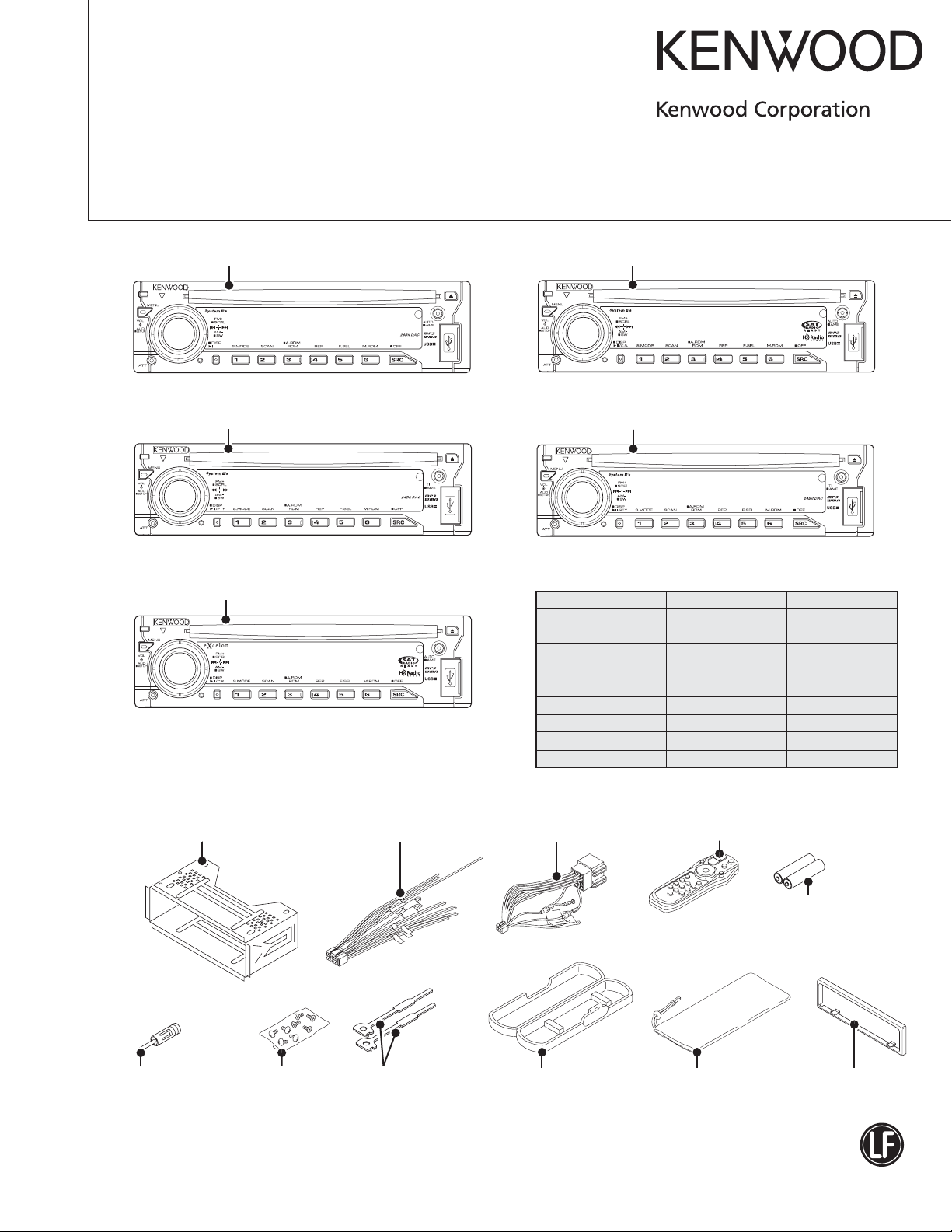
Panel assy
KDC-MP4036U (A64-4129-12)
Panel assy
KDC-W4537Uxx (A64-4127-12)
Panel assy
KDC-X491 (A64-4221-12)
KDC-MP4036U
KDC-W4537U
KDC-X491
Panel assy
KDC-MP435U (A64-4126-12)
KDC-MP435U
Panel assy
KDC-MP4737U/MP4737UY (A64-4175-12)
KDC-W4737U
SPARE TDF PANEL
MAIN UNIT NAME TDF PARTS No. TDF NAME
KDC-MP4036U Y33-2720-64 TDF-MP4036U
KDC-MP435U Y33-2720-61 TDF-MP74D
KDC-W4537UA Y33-2720-63 TDF-W4537U
KDC-W4537UAY Y33-2720-63 TDF-W4537U
KDC-W4537UG Y33-2720-63 TDF-W4537U
KDC-W4537UGY Y33-2720-63 TDF-W4537U
KDC-W4737U Y33-2720-62 TDF-W4737U
KDC-W4737UY Y33-2720-62 TDF-W4737U
KDC-X491 Y33-2720-60 TDF-MP74DX
Mounting hardware assy
(J21-9716-03)
* Antenna adaptor
(T90-0523-05)
* Depends on the model. Refer to the parts list.
* Screw set
(N99-1757-05)
* DC cord
(E30-6428-05)
Lever
(D10-4589-04) x2
* DC cord
(E30-6671-05)
* Plastic cabinet assy
(A02-2736-03)
This product complies with the
* Remote controller assy (RC-xxx)
(A70-xxxx-xx)
Battery
(Not supplied)
* Carrying case
(W01-xxxx-xx)
This product uses Lead Free solder.
RoHS directive for the European market.
Escutcheon
(B07-3125-01)
KDC-MP4036U/MP435U/X491/W4537UA/W4537UAY
/W4537UG/W4537UGY/W4737U/W4737UY
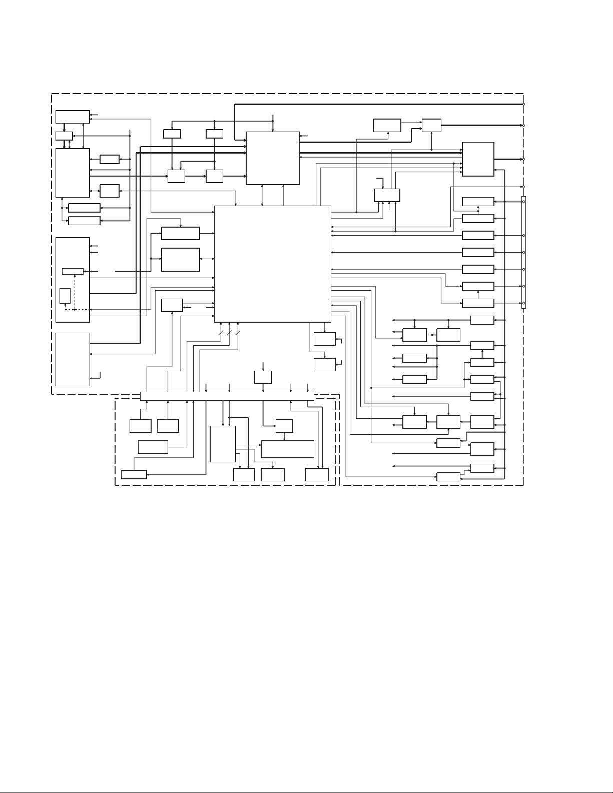
BLOCK DIAGRAM
ELECTRIC UNIT (X34- )
DME1
IC703
DIR
SOC
A500
FRONT-END
E2PROM
FST
MPX for RDS
J601
LX BUS
CD
IC711
SD RAM
NOR FLASH
SWITCH UNIT
SERVO
IC716
D1.8V
IC709,710,712
LEVEL
SHIFT
IC714
IC715
AM+B
A8V
SW5V
BACK
UP
(X16- )
D3.3V
J200
J1
S1
RESET
SW
REMOTE
S2
ROTARY
ENCODER
IC705 IC705
D5V
IC700
2ch
DAC
IC500
RDS
DECODER
IC101
INSTALLER
MEMORY
ROM
CORRECTION
IC100
RESET
IC BU5V
to
GND
PANEL
DET
CN600
A8V
BU5V
IC103
SERVO
SW MUTE
MUTE
DRIVER
USB5V
IC704
215
ILLUMI+B
IC300
AUX (ISO IN)
CH
FM/AM
E-VOL
CD
SYSTEM
u-COM
FL+B
R224
1/2W
Rx1
ED1
KEY KEY
ILLUMI
MATRIX
R17
1/2W
Rx1
USB I/F
for SOC
(IC711)
FL
4VPRE+B
PRE MUTE
USB5V
J2
USB CN
MUTE
DSI
PANEL
5V
Q200
Q15
BU5V
A5V
LPF
IC102
PAN SW5
CN
IC1
FL
DRIVER
RST
Q600,602-605,607Q601,606
Q15
PANEL
5V
Q300,302
4VPRE
Q500,501
AM+B
HI-SIDE
SW
PRE
MUTE
Q13,14
Q20
Q21
SW 5V
IC1IC100
USB 5V
FDC
SW 14V
SW 14V
IC400
POWER
IC
OFFSET
Q51
BU DET
Q59
SURGE DET
R62,C57,D58
TEL MUTE
Q57
ACC DET
Q60
DIMMER
Q53,56
ANT-CON
Q50,58
P-CON
Q3,4
BU 5V
Q1,2,16
A8V
Q17
SW 14V
Q6
SW 14V
Q5,7
SERVO
Q8,9
SW 20V
Q301
4VPRE
+B
Q10-12,18
ILL+B
J600
WH1
AUX I N
PRE OUT
(FRONT)
PRE OUT
(REAR)
PRE OUT
(SW)
SP OUT(FL)
J1
SP OUT(FR)
SP OUT(RL)
SP OUT(RR)
WIRED
REMOTE
J1
BACK UP
LINE
ACC
DIMMER
ANT CON
P CON
2
KDC-MP4036U/MP435U/X491/W4537UA/W4537UAY
/W4537UG/W4537UGY/W4737U/W4737UY
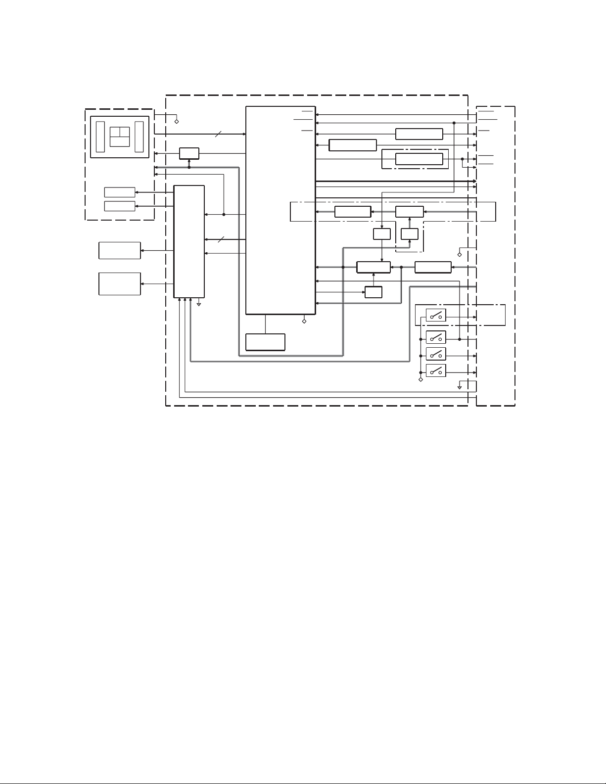
BLOCK DIAGRAM
DPU1
A
E
C
FO COIL
TR COIL
DM1
SPINDLE
MOTOR
DM2
LOADING &
SLED
MOTOR
CD PLAYER UNIT (X32-598x-xx)
IC1
D.G ND
Q7
APC
FO OUT
TR OUT
VREF
MOTOR
DRIVER
DM OUT
FM OUT
S.GND
A,B,C,E,F
FOD,TRD,
TVD,SPL
1 CHIP IC
RF AMP
+
SERVO
PROCESSOR
+
MICRO
PROCESSOR
VREF
DMUTE
X1 or
X2
CLOCK
16.93MHz
B
F
IC6
RST
MSTOP
CLK
DATA
AVD D
IOVDD
P-ON1
REGVDD
D.G ND
LEVEL SHIFT
IC3
3.3V REG
Q8,9
Q6
3.3V SW
SW
Q3
LEVEL SHIFT
Q3
Q4
LEVEL SHIFT
(0-00),(0-01) ONLY
8V SW
SW
SW
Q1
Q2
(0-00),(0-01)
ONLY
IC2
3.3V REG
(0-01),(0-03)
ONLY
D.G ND
D.GND
S.GND
S4
S3
S2
S1
MOTHER
BOARD (X34- )
MRST
MSTOP
CLK
DATA
MUTE
MUTE
L-ch
R-ch
A.GND
AS8V
D.G ND
BU5V
S7V
8EJE-SW
LOE/LIM-SW
12EJE-SW
LOS-SW
S.GND
LO/EJ
MOTOR
3

KDC-MP4036U/MP435U/X491/W4537UA/W4537UAY
/W4537UG/W4537UGY/W4737U/W4737UY
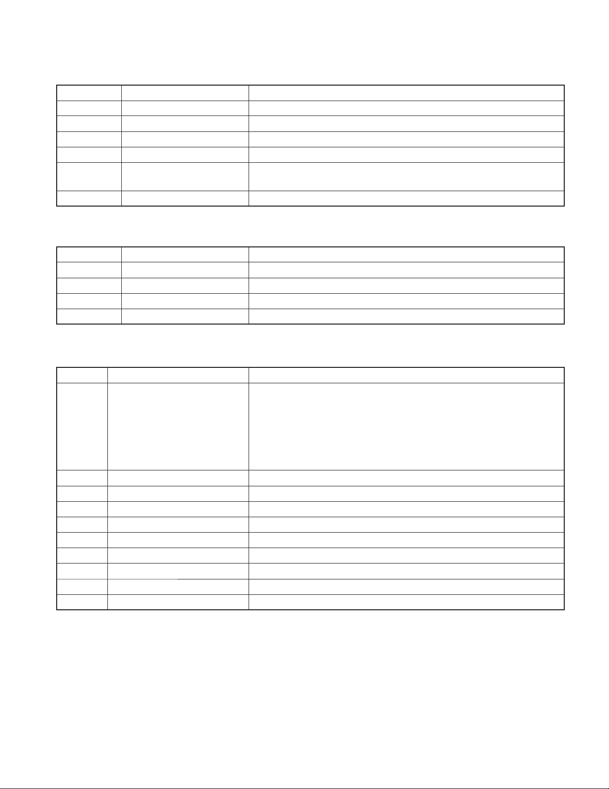
COMPONENTS DESCRIPTION
ELECTRIC UNIT (X34-466x-xx)
●
Ref. No. Application / Function Operation / Condition / Compatibility
IC1 SW REG Outputs 5.0V. Power supply for D5V, FL+B and USB5V.
IC2 A8V REF Power Supply Outputs 1.27V.
IC100 Reset IC Lo when detection voltage goes below 3.6V.
IC102 System µ-COM Controls FM/AM tuner, the changer, CD mechanism, USB, panel, volume and tone.
IC103 Muting Logic IC Controls logic for muting.
IC200 Hi-side SW
IC300 E-VOL Controls the source, volume and tone.
IC301 OP-AMP Reference supply for 4V pre-out.
IC400 Power IC Amplifi es the front L/R and the rear L/R to 50W maximum.
IC500 RDS Decoder Decodes RDS signal.
IC700 D/A Converter. For CD and USB source.
IC702 iPod Authentication Coprocessor For iPod authentication.
IC703 Digital Audio Receiver For CD source.
IC704 OP-AMP L.P.F.
IC705 Point REG Outputs 5.0V. Power supply for D/A converter.
IC708 DC Voltage REG Outputs 3.3V. Power supply for 3.3V.
IC709,710 Inverted 3-state Output Converts 3.3V to 5V.
IC711 SOC (System On Chip)
IC712 Quad 2-input AND Gate Convert 5V to 3.3V.
IC714 SDRAM SDRAM for SOC.
IC715 NOR Flash ROM NOR fl ash ROM for SOC.
IC716 LDO REG Outputs 1.8V. Power supply for SOC.
Q1,2,16 A8V AVR When Q16’s base goes Hi, A8V AVR outputs 8.0V.
Q3,4 BU5V AVR While BU is applied, BU5V AVR outputs +5V.
Q5,7 Servo+B AVR When Q7’s base goes Hi, Servo+B AVR outputs 7.5V.
Q6,17,20,21 SW14V When Q17’s (or Q21's) base goes Hi,SW14V outputs 14V.
Q8,9 Serge Protect for IC1 Output 20V when BU is over 20V.
Q10,11,12,18 ILL+B AVR When Q18’s base goes Hi, ILL+B outputs 10.5V.
Q13,14 SW5V When Q14’s base goes Hi, SW5V outputs +5V.
Q15 PAN5V When the base goes Lo, PAN5V outputs 5V.
Q50,58 P-CON SW When Q50’s base goes Hi, AVR outputs 14V.
Q51 BU DET When the base goes Hi, Q51 is turned on.
Q52,54 P-CON Protection
Q53,56 P-ANT SW When Q53’s base goes Hi, P-ANT SW outputs 14V.
Q57 ACC DET When the base goes Hi, Q57 is turned on.
Q59 Serge DET When the base goes Hi, BU DET is turned off.
Q60 Small Lamp DET SW When the base goes Hi, Q60 is turned on.
Q200 DSI When the base goes Hi, security indicator lights.
Overcurrent protection of USB power supply.
When pin1 goes Hi, USB5V is ON.
Decodes MP3 or other fi les of audio/decompression standards by software based
architecture.
When P.CON output voltage decrease is detected, output protection is made.
When P.CON SW is ON, malfunction of Q58 is protected.
4
KDC-MP4036U/MP435U/X491/W4537UA/W4537UAY
/W4537UG/W4537UGY/W4737U/W4737UY
COMPONENTS DESCRIPTION
Ref. No. Application / Function Operation / Condition / Compatibility
Q300,302 4VPRE+B Protect When 4VPRE+B is overcurrent, Q300 and Q302 turn Q301 off.
Q301 4VPRE+B AVR When Q300’s base is 8V, 4VPRE+B outputs 7.4V.
Q500,501 AM+B When Q501’s base goes Hi, AM+B is output.
Q601,606 Pre-out Mute Driver When a base goes Lo, mute driver is turned on.
Q600,602,603,
Q604,605,607
Q704,706 M-RST Converter Converts 3.3V to 5V.
SWITCH UNIT (X16-389x-xx)
●
Ref. No. Application / Function Operation / Condition / Compatibility
IC1 FL Driver
IC3 Remote Control Sensor
Q1 LED LED SW On when the base goes Hi. (RED LED lights)
Q2 GREEN LED SW On when the base goes Hi. (GREEN LED lights)
Pre-out Mute SW When a base goes Hi, pre-out is muted.
CD PLAYER UNIT (X32-5980-02)
●
Ref. No. Application / Function Operation / Condition / Compatibility
Focusing, tracking, sled and spindle servo processing.Automatic adjustment (focusing,
tracking, gain, offset and balance) operations. Digital signal processing (DSP, PLL,
CD Signal Processor & MECHA
IC1
IC2 3.3V REG Supplies 3.3V to IC1 and the laser pick-up.
IC6 4ch BTL Driver
Q3 5V-3.3V Level Shift Shifts 5V to 3.3V, or 3.3V to 5V.
Q6 BU3.3V SW Q6 is ON when Q8 or Q9 is ON.
Q7 APC (Auto Power Control) Drives LD (Laser Diode).
Q8 Power Supply Control
Q9 Power Supply Control
D1,2 5V Force Voltage Prevention 5V Force Voltage Prevention from MECHA µ-COM side.
D3 Laser Diode Protection Prevents reverse bias which is applied to laser. Laser destruction prevention.
µ-COM RF Amplifi er responding to
CD-RW
sub-codes, CIRC error correction, audio data interpolation processing) operations,
and microcomputer function. Generation of RF signal based on the signals from the
APC circuit and the laser pick-up, and generation of servo error (focusing error and
tracking error) signals. Detection of dropout, anti-shock, track crossing and off-tracking
conditions, included gain control function during CD-RW.
Focusing and tracking coil, sled and spindle motor driver, disc loading and eject operation.
Power Supply Control from MECHA µ-COM. Q6 is ON when pin 63 (P ON1) of IC1 is Hi.
Power Supply Control from system µ-COM. Q6 is ON when pin 125 (MSTOP) of IC1 is Hi.
5

KDC-MP4036U/MP435U/X491/W4537UA/W4537UAY
/W4537UG/W4537UGY/W4737U/W4737UY
MICROCOMPUTER’S TERMINAL DESCRIPTION
SYSTEM µ-COM: IC102 on X34- (ELECTRIC UNIT)
●
Pin No.
1 REMO I
2 LX REQ M O Communication request to slave unit
3 LX MUTE I Communication request from slave unit H: Mute ON, L: Mute OFF
4 LX CON O Start-up request to slave unit H: Slave unit ON, L: Slave unit OFF
5 LX RST O Forced reset to slave unit H: Reset, L: Normal condition
6 BYTE -
7 CNVSS -
8 XCIN - Sub clock 32.768kHz
9 XCOUT - Sub clock 32.768kHz
10 RESET -
Pin Name I/O Application
External display remote control input
Panel remote control input
Truth
Value Table
Processing / Operation / Description
Panel attached: Pull-up
Panel detached: Pull-down
11 XOUT - Main clock 12.00MHz
12 VSS -
13 XIN - Main clock 12.00MHz
14 VCC1 -
15 NMI -
16 LX REQ S I Communication request from slave unit
17 RDS CLK I RDS decoder clock input
18 PANEL DET I
19 PON AM I/O AM power supply control AM reception: H, No AM reception: Hi-Z
20 TUN IFC OUT I Front-end IFC-OUT input H: Station found, L: No station
21 RDS AFS M I/O Noise detection time constant SW
22 RDS QUAL I RDS decoder QUAL input
23 RDS DATA I RDS decoder data input
24 USB SYNC O Clock output for SW-REG
25 NC - Not used Output L fi xed
26 PWIC BEEP O Beep output
27 TUN SCL I/O Front-end I2C clock input/output MAX400kHz
Detection of panel connector detached/
attached
H: Panel detached, L: Panel attached
28 TUN SDA I/O Front-end I2C data input/output
29 VFD SYS DATA I/O VFD data input/output
30 VFD PAN DATA I VFD INT input
31 VFD CL O VFD clock output 125kHz
32 VFD BLK O VFD reset
33 S SYS DATA O System µ-com→SOC data
34 S SOC DATA I SOC→System µ-com data
6
H: Reset cancelled, L: Reset
Momentary power down or Panel detached or 11
minutes after ACC OFF: L

KDC-MP4036U/MP435U/X491/W4537UA/W4537UAY
/W4537UG/W4537UGY/W4737U/W4737UY
MICROCOMPUTER’S TERMINAL DESCRIPTION
Pin No.
35 S SOC SCL I SOC→System µ-com clock
36-38 NC - Not used Output L fi xed
39 ROMCOR DET I E2PROM writing request H: Writing
39 EPM I EPM input when writing
40 DSI I/O DSI control
41 CD DISC12 SW I 12cm CD detection
42 CD LOS SW I CD loading detection
43 CD MUTE I CD mute request L: Mute request, H: Normal condition
44 VFD CE O VFD control request H: VFD data transfer ready
45 SOC S RST O SOC reset H: Normal condition, L: Reset
46 SOC S STOP O SOC stop H: Normal condition, L: SOC stopped
47 NC - Not used Output L fi xed
48 CD LOE LIM SW I CD detection (Chucking SW) H: Loading completed, L: No disc
49 CD LOEJ I/O CD motor control
50 CD MOTOR O CD motor control
51 ROTARY CW I VOL key detection
52 ROTARY CCW I VOL key detection
53 PON PANEL I/O Panel 5V power supply
54 PON FL+B I/O FL fi lament power supply H: ON, Hi-z: OFF
Pin Name I/O Application
Truth
Value Table
q
q
Processing / Operation / Description
Refer to the truth value table
Refer to the truth value table
Detects pulse
15-pulse/360°, 2-pulse/1-click
Detects pulse
15-pulse/360°, 2-pulse/1-click
ON (For 11 minutes after ACC OFF): L
Momentary power down or Panel detached or 11
minutes after ACC OFF: Hi-Z
55 SW USB I/O VBUS5V control
56 NC - Not used Output L fi xed
57 PON ILL O Key illumination power supply H: Power ON, L: Power OFF
58,59 NC - Not used Output L fi xed
60 VCC2 -
61 PON O Power supply control H: Power ON, L: Power OFF
62 VSS -
63,64 TYPE 1,2 I Destination setting
65 NC - Not used Output L fi xed
66 PCON O External amplifi er control
67~69 NC - Not used Output L fi xed
70 ANT CON O Power antenna control Tuner ON: H
71 NC - Not used Output L fi xed
72 ACC DET I ACC power supply detection ACC found: L, No ACC: H
73 BU DET I Detection of momentary power down BU found: L, Momentary power down: H
H: ON, Hi-z: OFF (Depends on command order from
SOC)
Refer to the truth value table
w
7
KDC-MP4036U/MP435U/X491/W4537UA/W4537UAY
/W4537UG/W4537UGY/W4737U/W4737UY
MICROCOMPUTER’S TERMINAL DESCRIPTION
Pin No.
74 ILLUMI DET I Dimmer illumination detection L: ON, H: OFF
75 S SYS REQ O
76 S SOC REQ I
77 PWIC MUTE O Power IC mute control
78 PWIC STBY O Power IC standby control
79 LINE MUTE I Line mute detection TEL mute: Below 1V, NAVI mute: Over 2.5V
80 PWIC DC DET I DC offset detection
81 IC2 SDA I/O I2C data input/output
82 IC2 SCL I/O I2C clock input/output
83 NC - Not used Output L fi xed
84 MUTE AFS I/O AFS mute L: Mute ON, Hi-Z: Mute OFF
85 MUTE 0 O E-VOL front mute L: ON, H: OFF
86 MUTE 1 O E-VOL rear mute L: ON, H: OFF
87 MUTE 2 O E-VOL SW mute L: ON, H: OFF
88 MUTE PRE FR O PRE-OUT mute for FR
89 MUTE PRE SW O PRE-OUT mute for SW L: Mute ON, H: Mute OFF
Pin Name I/O Application
Communication request of system µ-com
SOC
→
Communication request of SOC→system
µ-com
Truth
Value Table
Processing / Operation / Description
Mute is L during CD play: L
Momentary power down: L
Only condition when DUAL ZONE or NAVI INT: H fi xed
90,91 NC - Not used Output L fi xed
92 RDS NOISE I FM noise detection
93 TUN SMETER I S-meter input
94 AVSS -
95 NC - Not used Output L fi xed
96 VREF -
97 AVCC -
98 LX DATA S I Data from slave unit
99 LX DATA M O Data to slave unit
100 LX CLK I/O LX-BUS clock
Destination setting
Truth value table
CD motor control
q
CD MOTOR (Pin50) CD LOEJ (Pin49)
Stop L L
Load H L
Eject H H
Brake H Hi-z
w
TYPE 2 (Pin64) TYPE 1 (Pin63) MODEL
0V 0V KDC-MP435U
0V 1.2V KDC-X491
0V 2.4V VISTEON
1.2V 0V KDC-MP4036U
2.4V 0V KDC-W4537UA
2.4V 1.2V KDC-W4537UG
2.4V 2.4V KDC-W4737U
3.6V 0V KDC-W4537UAY
3.6V 1.2V KDC-W4537UGY
3.6V 2.4V KDC-W4737UY
5V 0V U525
8

KDC-MP4036U/MP435U/X491/W4537UA/W4537UAY
/W4537UG/W4537UGY/W4737U/W4737UY
TEST MODE
How to enter the test mode
●
Press and hold the [1] and [3] keys and reset.
(While “– – – –” is being displayed, power can be ON for
30 minutes.)
How to clear the test mode
●
Reset, momentary power down, Acc OFF, Power OFF,
detach the panel.
Test mode default condition
●
• Source is STANDBY.
• Display lights are all turned on.
• The volume is at 30 (-10dB).
• LOUD is OFF.
• CRSC is off regardless of the availability of switching
function.
• SYSTEM Q is NATURAL (=FLAT).
• BEEP should always function when the key is pressed
briefl y.
• AUX is ON (Internal AUX supporting model).
Speciication of the test mode for tuner sourse
●
The frequency of 98.3MHz is received when the [4] key is
pressed in the TUNER FM mode
Specifi cation of FST soft mute adjustment mode
●
1. Receive the TUNER FM mode in the VOLUME 30 and
LOUD OFF condition.
2. Press and hold the [
FST soft mute adjustment mode.
3. In the adjustment mode, the following display is shown.
Adjust the mute between 0 (18dBu) and F (36dBu) with
the [FM] / [AM] keys.
(Display) SMD–x_ _ _ (Adjustment value, 0~F is displayed
in “x”).
4. When the adjustment is “OK”, press and hold the [
for 2 seconds again to write the adjustment value in
the E2PROM, and after the successful writing-in the
“EP_WRITE” is displayed.
5. Press the [
adjustment mode.
(The test mode continues.)
key briefl y to exit from the FST soft mute
]
key for 2 seconds to enter the
]
] key
OFF the P-CON terminal. ( The symbol, “_” indicates the
blank. )
→ Make this as the process dedicated for the test mode.
P-CON is recovered by Power OFF→ON.
Special display in tuner mode
●
Error is found in front-end, etc. if indications below are
displayed while in tuner mode.
• “TNE2P_NG” : E2PROM (in front-end: A500 of X34-)
values are still default (not determined)
• “TNCON_NG” : Cannot communicate with the front-end.
K3I forced switching
●
Every time when [6] key is pressed in tuner FM mode,
switched in the following order: AUTO→Forced WIDE
Forced MIDDLE→Forced NARROW→AUTO. Default
→
status is AUTO, and displayed as shown below.
• AUTO: FM1_98.1A • Forced WIDE: FM1_98.1W
•
Forced MIDDLE: FM1_98.1M
CD source test mode specifi cation
●
• Display mode default setting shall be P-TIME.
• Jumps to the following tracks by pressing the [ ] key.
No.9→No.15→No.10→No.11→No.12→No.13→No.22
No.14→No.9 (recursive)
Note that when playing a CD-DA disc and MP3 / WMA
/ AAC / WAV discs with 8 fi les or less, the disc is played
from the 1 track in the normal order.
• Pressing the [
being played.
• When playing an MP3 / WMA / AAC/WAV disc, display
the fi le format before starting to play each fi le.
( “MP3”, “WMA”, “AAC”, “WAV” )
• While in CD source, press the [1] key briefl y to jump to
No.28.
• While in CD source, press the [2] key briefl y to jump to
No.14.
• While in CD source, press the [3] key briefl y to display CD
mechanism model name and the version.
Press the [3] key briefly again to return to the normal
display. (Time code display)
] key goes back by 1 track from the track
•
Forced NARROW: FM1_98.1N
→
RDS automatic measurement
●
Add the process to replace the visual inspection of PS
display previously done in the production line.
When it is confi rmed that the PS data has been received
and that the content of the PS is “RDS_TEST”, force to
6C20:0123
Model name Version
• While in CD source, press the [6] key briefl y to jump to
No.15. At this time, the volume value is set to 25 (2V
PRE), 27 (4V PRE).
9
KDC-MP4036U/MP435U/X491/W4537UA/W4537UAY
/W4537UG/W4537UGY/W4737U/W4737UY
TEST MODE
AUDIO adjust mode
●
• Press the [AUD] key and enter the audio adjustment
mode.
• Press the remote control [∗] key and [AUD] key to enter
the audio adjustment mode.
• Both AUDIO FUNCTION MODE and SETUP MODE
adjustment items are included.
• By pressing [AUD] and [FM] key briefl y, switch the item
to be adjusted in the following order. (Only in forward
rotation)
The default item shall be Fader, and then the item is
forwarded in the following order: Balance → Bass Level
Middle Level → Treble Level → HPF Front → HPF
→
Rear → LPF Sub Woofer. (thereafter arbitrary)
• Continuous forwarding by remote control is prohibited.
• Fader is adjusted by the VOL knob and [
in 3 steps: R15 ↔ 0 ↔ F15. (Default value: 0)
• Balance is adjusted by the VOL knob and [ ] / [ ] keys
in 3 steps: L15 ↔ 0 ↔ R15. (Default value: 0)
• Sub Woofer Level is adjusted by the VOL knob and [ ] /
[ ] keys in 3 steps: -15 ↔ 0 ↔ +15. (Default value: 0)
• Bass/Middle/Treble Level are adjusted by the VOL knob
and [ ] / [ ] keys in 3 steps: -8 ↔ 0 ↔ +8. (Default
value: 0)
• HPF Front / Rear is adjusted by the VOL knob and [ ]
/ [ ] keys in 2 steps: Through ↔ 180Hz. (Default value:
Through)
• LPF Sub Woofer is adjusted by the VOL knob and [ ]
/ [ ]] keys in 2 steps: 60Hz ↔ Through. (Default value:
Through)
• Sub Woofer Phase is adjusted by the VOL knob and [ ]
/ [ ] keys in 2 steps: Reverse ↔ Normal. (Default value:
Normal)
• Volume Offset (other than the internal AUX) is adjusted
by the VOL knob and [ ] / [ ] keys in 2 steps: -8 ↔ 0.
(Default value: 0)
• Volume Offset (the internal AUX) is adjusted by the VOL
knob and [ ] / [ ] keys in 3 steps: -8 ↔ 0 ↔ +8. (Default
value: 0)
• Loudness ON/OFF is adjusted by the VOL knob and [ ]
/ [ ] keys in 2 steps: OFF ↔ ON. (Default value: OFF)
• Dual Zone ON/OFF is adjusted by the VOL knob and
[ ] / [ ] keys in 2 steps: OFF ↔ ON. (Default value:
OFF)
• Bass f / Bass Q / Bass EXT / Middle f / Middle Q / Treble f
are not displayed in the audio adjustment menu.
• SYSTEM Q (dB EQ) curve selection is not displayed in
the audio adjustment menu.
] / [ ] keys
MENU
●
• Press [MENU] key briefl y to enter the MENU.
• Press the remote control [DNPP/SBF] key and the
[DIRECT] key to enter the MENU.
• Continuous forwarding by remote control is prohibited.
• Only in the test mode, make the USB source MENU show
the F/W Version check item and make the F/W Version be
shown as the initial items in the test mode.
Dual Zone (Dual Zone specification supporting
●
model)
• If the [AUTO] or [TI] keys is pressed briefly while in a
source other than STANDBY, Dual Zone is switched
between ON / OFF.
Backup current measurement
●
If reset while in Acc OFF (Back Up ON) condition, MUTE
terminal goes off 2 seconds later, rather than 15 seconds.
(During this time, the CD mechanism does not function.)
Special displays while all lights are on
●
When all lights are on with STANDBY source, if the
following keys are pressed, the following messages are
displayed.
[1]
Key pressed briefl y: Version is displayed (forwarding)
key
(Display) TYPE : xx_ _ _ → 632K–1.02 → All lights are on
(“xx” is displayed in hexadecimals.) [“Development
name” – “version”]
TYPE indicates µ-com destination, and shows real-time
∗
condition of the destination terminal.
[2]
Key pressed briefl y: Serial No. is displayed (8 digits)
key
(Display) xxxxxxxx
[3]
Key pressed briefl y: Power ON time is displayed.
key
Press and hold: To clear Power ON time (Press and hold for
2 seconds while the Power ON time is displayed.)
(Display) PON_0Hxx (00~50 is displayed for “xx”. When less
than 1 hour, display by increment of 10 minutes.)
xxxxx (00001~10922 is displayed for “xxxxx”)
MAX 10922 (hours)
[4]
Key pressed briefl y: CD operation time displayed.
key
Press and hold: To clear CD operation time (Press and hold
for 2 seconds while the CD operation time is displayed.)
(Display) CDT_0Hxx (00~50 is displayed for “xx”. When less
than 1 hour, display by increment of 10 minutes.)
xxxxx (00001~10922 is displayed for “xxxxx”)
MAX 10922 (hours)
→
10
[5]
Key pressed briefl y: Number of CD EJECT times is
key
displayed.
Press and hold: To clear CD EJECT times (Press and hold
for 2 seconds while the CD EJECT time is displayed.)
(Display) EJCxxxxx MAX 65535 (times)
[6]
key
[FM]
Key pressed briefl y: ROM correction version is displayed.
key
When E2PROM is not installed: ERR_
When not written in: R – – – – _ _ _
(Display) R1234 _ _ _ When data not matching: R
[]
Key pressed briefl y: AUDIO data initialization
key
(Display) AUD_INIT
[ ]
Key pressed briefl y: Forced Power OFF data displayed.
key
Press and hold: To clear the forced power OFF information.
(Press and hold for 2 seconds while the forced power OFF
data is displayed.)
(Display) POFF _ – – – (No Forced Power OFF)
SEC (Forced Power OFF because of
missing Security Code)
PNL (Forced Power OFF because
of system µ-com and panel
communication error)
[AUD]
Key pressed briefl y: iPod authentication IC installation status
key
display (iPod 2Wire supporting model)
(Display) iPOD_ OK_ (Installation status OK)
NG (Installation status NG)
[ ]
Key pressed briefl y: CD information display mode ON
key
Please refer to the next table.
∗
CD information display mode
●
I2C communication condition display
(Display) I2C_OK_ _
NG
CD mechanism error log display
(Display) MCERR1: xx ↔ MCERR2: xx ↔ MCERR3: xx ↔
MCERR1: xx ↔
(“– –” or an error code is displayed for “xx”.)
[AM]
CD loading error log display
key
(Display) LDERR1: xx ↔ LDERR2: xx ↔ LDERR1: xx ↔
MAX 99 (times)
(Number of times is displayed for “xx”.)
↑
CD ejection error log display
(Display) EJERR1: xx ↔ EJERR2: xx ↔ EJERR3: xx ↔
EJERR4: xx ↔ EJERR1: xx ↔
MAX 99 (times)
(Number of times is displayed for “xx”.)
[switched by [ ] / [ ] keys]
[switched by [ ] / [ ] keys]
[switched by [ ] / [ ] keys]
KDC-MP4036U/MP435U/X491/W4537UA/W4537UAY
/W4537UG/W4537UGY/W4737U/W4737UY
TEST MODE
CD time code error count data display (missing counts)
] / [ ] keys]
∗∗∗∗_ _ _
[switched by [
↓
(Display) CNT_LOSE ↔ CDDA_ _xx ↔ CDROM_xx ↔
CNT_LOSE
[FM]
MAX 99 (times)
key
(Number of times is displayed for “xx”.)
CD time code error count data display (count not updated)
[switched by [ ] / [ ] keys]
(Display) CNT_STAY ↔ CDDA_ _xx ↔ CDROM_xx ↔
CNT_STAY
MAX 99 (times)
(Number of times is displayed for “xx”.)
]
Key pressed briefl y: CD information display mode OFF
[
key
Press and hold: To clear entire CD information (Press and
hold for 2 seconds)
Initializing AUDIO-related setting value
●
↔
↔
Press the [ ] key briefl y in the STANDBY source and
reset the AUDIO setting value to the test mode default
value.
Fluorescent tube short-checking
●
Change the process in the following order by pressing
[ATT] key briefl y while in STANDBY source.
1. All lights off.
2. Every 125msec, light the odd and even number terminals
of the grid with the largest numbers.
3. Lights only odd number terminals.
4. Lights only even number terminals.
5. All lights on.
∗ After the step 5 above, return to the step 1 and repeat
thereafter.
Other
●
• When Power ON, do not display “CODE_NG”,
“CODE_OFF”, and “CODE_ON”.
• When the source is STANDBY, press [AUTO] or [TI]
keys briefly to switch key illumination between GREEN
and RED (GREEN ↔ RED). (in the model with ILLUMI
switching function)
• When the source is STANDBY, press and hold the [AUTO]
or [TI] keys for 1 second to switch the PREOUT between
Rear and Sub Woofer (Rear ↔ Sub Woofer). (1PREOUT
& 2PREOUT model)
• When started in the test mode, duration of prohibiting
LINE MUTE shall be changed from 10 seconds to 1
second.
• When in the test mode, do not write security code by
security jig.
11

KDC-MP4036U/MP435U/X491/W4537UA/W4537UAY
/W4537UG/W4537UGY/W4737U/W4737UY
TEST MODE
• When in the test mode, serial number is not written with a
serial-number-writing jig.
• When in the test mode, when DC offset error detection
is run, the detection information is not written into the
E2PROM.
• When in the test mode, even if the specified time has
passed, back-up memory items are not written into
E2PROM.
• DEMO mode shall not be operated while in the test mode,
CD Mechanism Information & Service Information & DC
Offset Error Detection Information Clear Mode, or DC
Offset Error Detection Information Clear Mode.
• Also, do not display DEMO ON/OFF option items in the
MENU in STANDBY source in the above modes.
Clearing CD mechanism information & service
●
information & DC offset error detection informa-
tion (Clearing E2PROM data)
1. While pressing and holding the [MENU] and [ATT]
keys, reset-start to start initializing the CD mechanism
information, service information and DC error detection
information.
(While “– – – –” is being displayed, power can be ON for
30 minutes.)
[CD mechanism information]
• Displays I2C communication condition
• Displays CD mechanism error log
• Displays CD loading error data.
• Displays CD ejection error data.
• Displays CD time code error count data (missing count).
• Displays CD time code error count data (count not
updated).
[Service Information]
• Displays power ON time is displayed.
• Displays CD operation time.
• Displays number of CD EJECT times.
• Displays number of times panel was opened/closed.
• Displays forced Power OFF data.
[DC offset error detection information]
• DC offset error detection display 1
• DC offset error detection display 2
2. After the initialization process is completed, the following
is displayed.
When successfully completed: “CD_O_ _ _”
When fi nished but unsuccessful: “CD_X_ _ _”
3. This mode is cancelled by resetting. (The last screen will
not be retained.)
(Note)
In this mode, the DC offset error detection display,
“PROTECT” is not shown.
Clearing DC offset error detection information
●
(E2PROM data clearing)
1. Press and hold [3] and [6] keys and reset-start to go into
the DC offset error display mode.
(While “– – – –” is being displayed, power can be ON for
30 minutes.)
2. While in STANDBY source, the current overall DC offset
error detection condition is displayed.
When not detected: “DC_ _OK_ _” : None of capacitor
leak, improper connection, etc. has been detected.
When detected: “DC_ _ERR_” : Any one of capacitor leak,
improper connection, etc. has been detected.
3. Use the following procedure to check the details of DC
offset error detection information.
[1]
Key pressed briefl y: DC offset error detection display 1 (To
key
show such detection as the improper connection and other
detection)
Key pressed and held for 2 seconds: Clear the information
that indicated if there was such an error as improper
connection and other error.
(Display) DC1_ OK_ _ (No error was detected)
ERR_ (Improper connection or other error is
detected.)
[2]
Key pressed briefl y: DC offset error detection display 2 (To
key
show the number of capacitor leaks.)
Key pressed and held for 2 seconds: Clear the information
that indicates the detected number of capacitor leaks.
(Display) DC2_ 0_ _ _ (No error was detected )
1 (Leak was detected once.)
2 (Leak was detected 2 times.)
3 (Leak was detected 3 times.)
4 (Leak was detected 4 times or more.)
4. DC offset error display mode is cancelled by resetting. (The
last screen will not be retained.)
(Note)
●
In this mode, the DC offset error detection display
“PROTECT” is not shown.
FM/AM channel space switching (KDC-MP4036U/
MP435U/X491 only)
While power is OFF, press and hold [1] and [5] keys, and
press [SRC] key to power ON.
Security
●
•
How to enter the forced POWER ON mode
While “_ _ _ _” is being displayed, while simultaneously
pressing [MENU] key and [4] key, press [RESET] button,
With this, it is possible to turn the power on for 30 minutes
only.
12

KDC-MP4036U/MP435U/X491/W4537UA/W4537UAY
/W4537UG/W4537UGY/W4737U/W4737UY
TEST MODE
• How to register the security code on the “Car
Audio Passport” sheet after replacing E2PROM
(in the front-end: A500 of X34-) (KDC-MP4036U/
W4537Uxx/W4737Ux only)
1. Enter the test mode. (Refer to “How to enter the test
mode”.)
2. In the test mode, press [MENU] key briefl y to enter the
MENU mode.
When “CODE_SET” is displayed, press [ ] key for 1
second or longer to enter the security registration mode.
3. Input the security code, using [FM] / [AM] / [ ] / [ ]
keys.
[FM] key : number up / [AM] key : number down
[ ] key : cursor to right / [ ] key : cursor to left
4. After inputting the code, press [ ] key for 3 seconds or
longer which causes “RE-ENTER” to be displayed. This is
for “confi rming” the code. Use the method in the step 3 to
re-enter the code.
5. Then, press [ ] key for 3 seconds or longer, which will
display “APPROVED”. This completes the security code
registration.
6. Release the test mode. (Refer to “How to clear the test
mode”.)
Note
*
: All clear cannot be used to clear the security code.
• How to clear the programmable security code
(KDC-MP435U/X491 only)
1. While “_ _ _ _” is being displayed, press [ ] key for 3
seconds or longer while pressing the [AUTO] or [TI] keys.
(This makes the “_ _ _ _” display disappear.)
2. Input “KCAR”, using the remote controller.
Press [5] key of the remote controller 2 times (Input for “K”)
and press [ ] key.
Press [2] key of the remote controller 3 times (Input for “C”)
and press [ ] key.
Press [2] key of the remote controller once (Input for “A”)
and press [ ] key.
Press [7] key of the remote controller 2 times (Input for “R”)
and press [ ] key.
3. The security is cleared and the unit enters STANDBY
source.
4. If wrong codes are input, “_ _ _ _” will be displayed again.
13
KDC-MP4036U/MP435U/X491/W4537UA/W4537UAY
/W4537UG/W4537UGY/W4737U/W4737UY
DC OFFSET ERROR
Purpose
●
Prevent customer’s vehicle speakers damages, burnouts,
and smoking.
Avoid the connected speakers to be burned out,
damaged, or to smoke when DC occurs between the
audio power amp. + and - outputs.
Processing after detection
●
• System status
• At the detection of DC error, error data is to be saved
immediately (E2PROM error log save area).
• Display the error message on the display. The system
shall maintain the current condition, including the
operation. Shut down audio system power supply. Set
Mute to ON.
• Although switching between Power OFF and ON (ACC,
BU, and Key operation) is valid, switching from Off to ON
shall be error until the µ-com is reset.
While power-on, even if the IC2VI DCErr output terminal
∗
logic recovered to normal level value, the error condition
shall continue.
• Prohibit to save the backup/installer memory to E2PROM
(nonvolatile memory).
• Controlling µ-com terminal
• Set Mute for all channels including for pre-out.
• Turn off power IC control system power supply. (Set AMP-
Standby function to valid)
• Set P-Con output to OFF (Logic by which external AMP
unit is turned off).
The purpose is to shut down audio output. Basically, the
∗
logic sets the audio output system signal line when in
Standby source.
• Key specifi cation
• Other keys than eject and power keys are invalid.
• Display specifi cation
• Display the “PROTECT” string and blink all characters at
1Hz.
Use the indication below with the highest priority (error
∗
message), and maintain the error message even when
the source is changed.
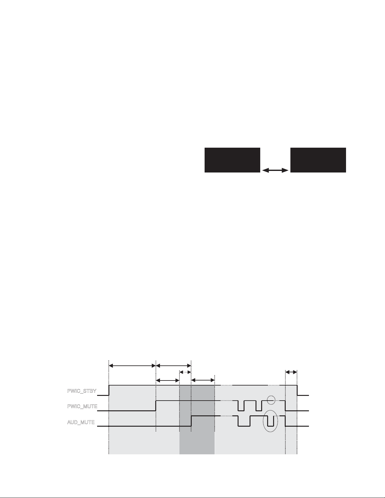
Display example
Blink
PROTECT
Cancel Condition
●
• Press the Reset terminal on the main body. Or set Backup
to OFF (Unplug and plug back in the DC connector).
The history is maintained (E2PROM data is saved).
• If DC error is detected during the capacitor leak detection
period, the clearing the error by the reset is limited to 4
times.
The startup is inhibited for the 5th time and later reset.
("PROTECT" display has to be blinked.)
Note while in the test mode
●
• While in the test mode, even if DC leak is detected, it is
not written into E2PROM.
When an error is detected, the display is enabled.
Other
●
• Function for checking and clearing data in E2PROM by a
given key shall be included. (Used at production dpt. and
service center, etc.)
alternately
at 1Hz
14
PWIC_STBY
PWIC_MUTE
AUD_MUTE
2.0sec or more 1.5sec or more
1.0s 1.0s
Improper connection
detection period
Capacitor leak
detection period
0.5s or more
(independent H→L→H)
AUD_MUTE
Other (improper detection etc.)
detection period
50ms
or more
 Loading...