

Kenwood KDC-8026, KDC-MP825, KDC-W7027 Service Manual
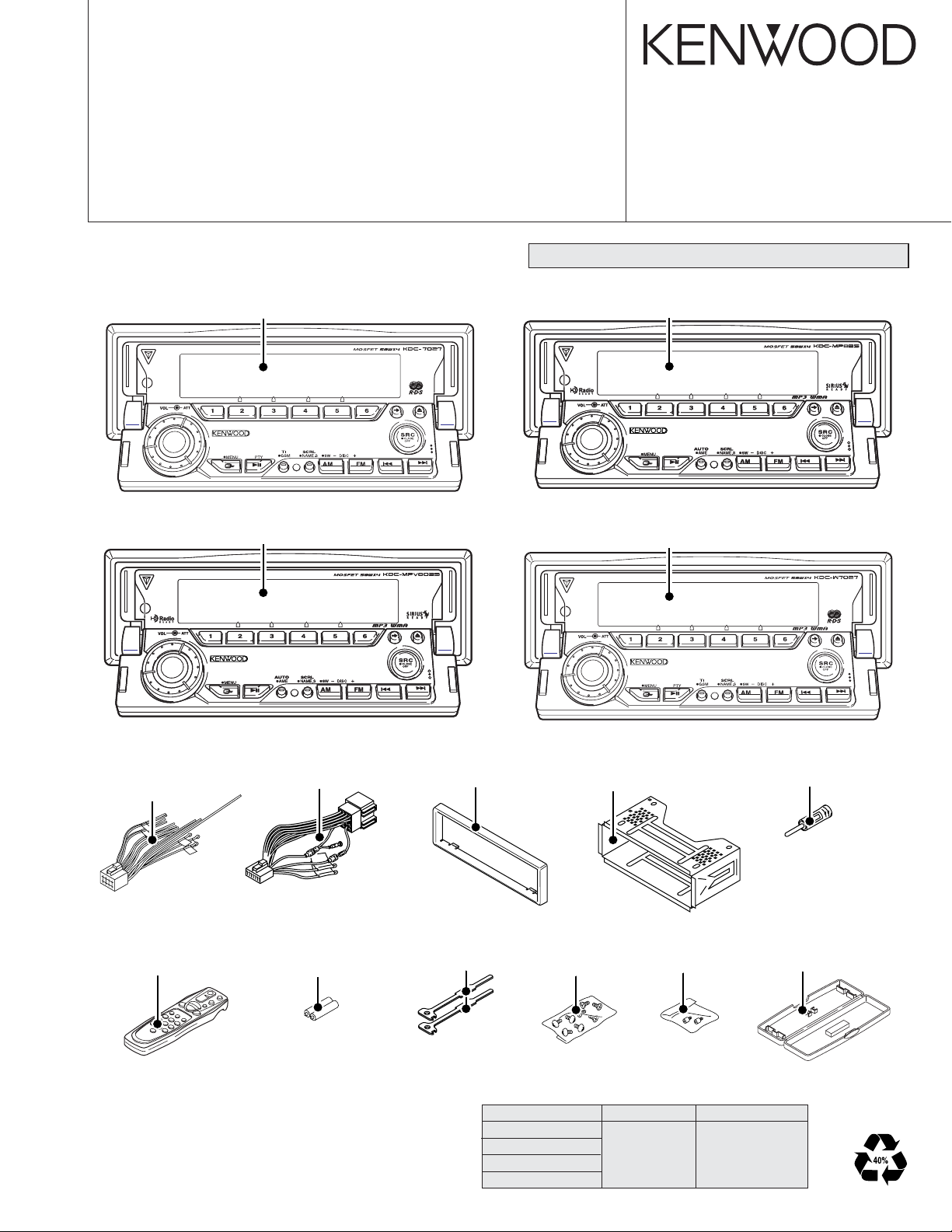
CD RECEIVER
KDC-8026
KDC-MP825
KDC-MPV8025
KDC-W7027
SERVICE MANUAL
© 2004-02 PRINTED IN JAPAN
B53-0130-00 (N) 2704
CD mechanism extension cord (24PIN) : W05-0935-00
Panel assy
KDC-8026 (A64-3231-01)
Panel assy
KDC-MPV8025 (A64-3228-01)
Panel assy
KDC-MP825 (A64-3229-01)
Panel assy
KDC-W7027 (A64-3223-01)
* DC cord
(E30-6294-05)
(E30-6295-05)
*Remote controller assy
(A70-2040-05) : RC-505
* Depends on model. Refer to the parts list.
* DC cord
(E30-4942-05)
*Size AA Battery
(Not Supplied)
Escutcheon
(B07-3078-01)
Lever
(D10-4674-04) x 2
TDF PANEL INFORMATION
MODEL PARTS NO. PANEL NAME
KDC-8026
KDC-MP825
KDC-MPV8025
KDC-W7027
Mounting hardware assy
(J21-9823-03)
*Screw set
(N99-1723-05)
Y33-1790-61 TDF-M7000
Screw
(N99-1734-05)
* Antenna adaptor
(T90-0552-05)
Plastic cabinet assy
(A02-2731-13)
KDC-8026/MP825
KDC-MPV8025/W7027
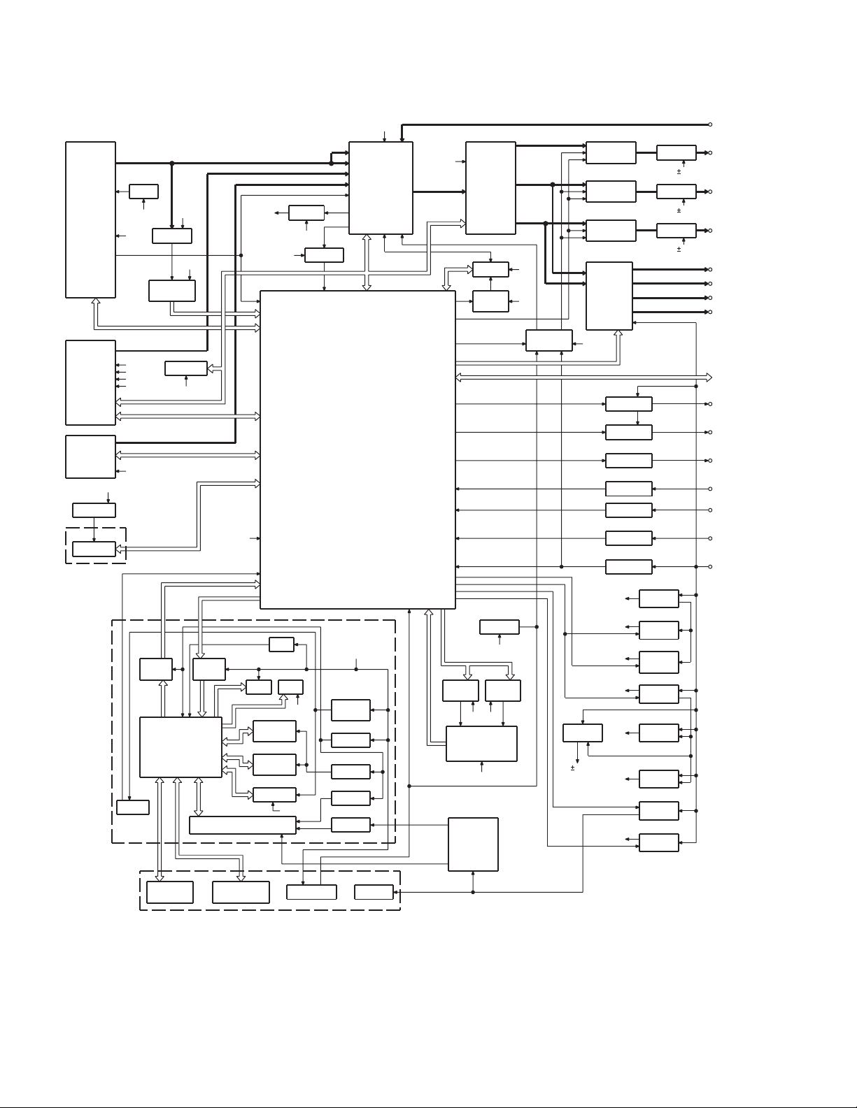
BLOCK DIAGRAM
(X34- )
TUNER
AUDIO OUT
S-METER
CD
CH
BU5V
Q501
EEP5V
IC1
EEPROM
TDF UNIT
(X16-208)
DISPLAY
UNIT
(X16-254)
(X16-255)
SWITCH UNIT
(X16-256)
Q303,304
AM+B
8V
BU5V
8V
SERVO
CD4.7V
BACK UP
IC9
REMO
8V 8V
BUFFER
IC14
RDS
DECODER
EEPROM
SW5V
IC7
LEVEL
SHIFT
IC11
u-COM
ROT ARY
ENCODER
SW5V
LEVEL
SHIFT
IC8
BU5V
IC2
IC4
IC10
FL
KEY
KEY MATRIX
BPF
IC1
MASK
ROM
FLASH
ROM
BPF
SW5V
2.5V
LEDLED
AGC
AGC
8V
BUFFER
SYSTEM
MICROPROCESSOR
ILL+
RESET SW
PANEL5
Q6,10
PANEL
SW5V
IC6
3.3V
Q5
SW3.3V
Q4
FL3.3V
Q2,3
FL+B
IC2
FM
AM
CD
CH
QUAL
E-VOL
MPX
KEY ILL
9V
9V
9V
AUX IN
PRE OUT
(SUB WOOFER)
PRE OUT
(REAR)
PRE OUT
(FRONT)
SP OUT (FL)
SP OUT (FR)
SP OUT (RL)
SP OUT (RR)
WIRED REMO/
OPEL DISP I/F
EXT.AMP.CON
TEL MUTE
ACC
BACK UP
8V
&
8V
IC15
MOTOR
FL+B
FAC
IC5
SYSTEM
E'S+
IC20
FOCUS
SW
IC8
SERVO
PANEL
MECHA
SW5V
DC/DC
WOW
RESET
IC16
MOTOR
DRDR
IC6
BU5V
IC9
8V
8V
MUTE
DRIVER
Q207,208
PRE MUTE
Q203,204
PRE MUTE
Q205,206
PRE MUTE
IC4
POWER
IC
BU5V
IC18
Q23,24
ANT-CON ANT CON
Q25
EXT AMP
Q26
DIMMER DIMMER
TEL MUTE
Q29
ACC DET
Q27
B.U DET
BU5V
SW5V
PANEL5V
SW14V
DC/DC A8V
9V
SERVO
CD4.7V
IC13
IC12
IC11
P-CON P CON
Q1,2
BU5V
Q3,601
SW 5V
Q502,503
PANEL
5V
Q4,5
SW 14V
Q6-8
A8V
Q9,602
SERVO
Q11-14
FL+B
IC19
SW REG
OP AMP
OP AMP
OP AMP
2
KDC-8026/MP825
KDC-MPV8025/W7027
COMPONENTS DESCRIPTION
● SUB CIRCUIT UNIT (X16-2080-10)
Ref No. Application / Functions Operation / Condition / Compatibility
IC1 E2PROM E2PROM for security
● DISPLAY UNIT (X16-2540-10)
Ref No. Application / Functions Operation / Condition / Compatibility
IC1 Driver LCD driver (Include KEY input function)
IC2 Driver LCD driver
IC3 Remote control IC For Remote control sensor
Q1 SW Key scan start SW “ON” when Q1 base level goes L
Q2 Red LED SW Red LED is turned on when Q2 base level goes H
Q5 VLCD AVR Reference voltage
Q6 SW Power supply control SW “ON” when base level goes L
Q11 Dimmer control LCD back light control “OFF” when Q11 base level goes L
D26 VLCD AVR Reference voltage
● DISPLAY UNIT (X16-2550-10)
Ref No. Application / Functions Operation / Condition / Compatibility
IC1 Driver LCD driver (Include KEY input function)
IC2 Driver LCD driver
IC3 Remote control IC For Remote control sensor
IC4 D/A converter For Variable illumination control
Q1 SW Key scan start SW ON when Q1 base level goes L
Q2 Red LED SW Red LED is turned on when Q2 base level goes H
Q5,D26 VLCD AVR Reference voltage
Q6 SW Power supply control SW ON when base level goes L
Q11-16 Illumination control Variable illumination control transistor
Q62-64 Illumination control Variable illumination control transistor
● SWITCH UNIT (X16-2560-11)
Ref No. Application / Functions Operation / Condition / Compatibility
Q1 DSI LED SW DSI LED blinks when Q1 base level goes H/L
Q2 KEY Illumination SW (Green) KEY Illumination SW “ON” when the Q2 base level goes H
Q3 KEY Illumination SW (Red) KEY Illumination SW “ON” when the Q3 base level goes H
Q4 KEY Illumination SW (Blue) KEY Illumination SW “ON” when the Q4 base level goes H
● CD PLAYER UNIT (X32-5540-00)
Ref No. Application / Functions Operation / Condition / Compatibility
IC1 Mechanism control microprocessor -
IC2 DSP CD signal processor, RF amp, Servo control
IC3 Decoder IC MP3/WMA decoder
IC4 BTL driver Focus, Tracking coil, Feed and Spindle motor driver IC
IC5 AVR SW3.3V AVR
IC6 AVR BU3.3V AVR
3
KDC-8026/MP825
KDC-MPV8025/W7027
COMPONENTS DESCRIPTION
Ref No. Application / Functions Operation / Condition / Compatibility
IC7 AVR BU2.5V AVR
IC8 Selector IC Serial audio data selector
IC9 AVR 3.3V AVR (IC2 DAC part)
Q1,4 Level shift FET Level shift (3.3V - 5.0V)
Q3,5 Level shift TR Level shift (3.3V - 5.0V)
Q6 Level shift TR Level shift (3.3V - 5.0V)
Q7 Level shift TR Level shift (3.3V - 5.0V)
Q8 APC Auto power control
Q9,10 Switching TR Sub beam delay control switch
● ELECTRIC UNIT (X34-3040-10/11/21, X34-3042-71)
Ref No. Application / Functions Operation / Condition / Compatibility
IC1 System control IC System control microprocessor
IC2 E-VOL & tuner IC E-VOL. FM/AM tuner & stereo decoder
IC3 Power supply IC For A8V AVR
IC4 Audio power IC Audio power amplifier
IC5 Power supply IC Switching regulator IC for CD5V
IC7 Reset IC When BU5V line voltage is less than 3.5V, this IC output line is “L”
IC8 Muting logic IC Control for MUTE, P-ANT & RESET muting
IC12 RDS decoder Decode for RDS signal
IC13,14 Motor driver Control for Panel mechanism motor
Q1,2 BU 5V AVR While BU is applied when BU5V regulator output is +5V
Q3 SW5V AVR When Q3base level goes L, SW5V regulator output is +5V
Q4,5 SW14V AVR When Q5 base level goes H, SW14V regulator output is +14V
Q6-8 Audio 8V AVR When Q6 base level goes H, A8V regulator output is +8.4V
Q9,34 Servo +B AVR When Q34 base level goes H, S+B regulator output is +7.4V
Q11~14 Illumination +B AVR When Q11 base level goes H, AVR output is +10.5V
Q23,24 P-ANT SW When Q23 base level goes H, P-ANT SW output is +14V
Q25,26 P-CON SW When Q26 base level goes H, P-CPN SW output is +14V
Q27,28 P-CON protection Protect Q27 by turning on when P-CON output is grounded
Q29 Buffer EX amp control buffer
Q30 Small lamp det. SW When Q30 base level goes H, Q30 turned ON
Q32 BU detector When Q32 base level goes H, Q32 turned ON
Q33 ACC detector When Q33 base level goes H, Q33 turned ON
Q51,52 Muting driver When base level goes L, muting driver is turned ON
Q55,56,59,60
Q63 E2P 5V SW When Q63 base level goes L, E2P 5V is out for E2P ROM
Q102,103 AM +B SW When Q102 base level goes H, AM +B is out to tuner unit
Q104 Buffer Composite signal buffer for RDS
Pre-out muting SW When base level goes H, Pre-output is muted
4
 Loading...