

Page 1

Programming Instructions for:
Kenwood TK-780, 880, 980, 981 (Version 2)
W/ KCT-19 Option Connector
For use with:
Pyramid Communications
Model 2012/2016/Merlin
Revision E
November 25, 2002
1
Page 2

Introduction ....................................................................................................................3
Programming the Pyramid 2012/Merlin ..........................................................................3
Radio Format ..............................................................................................................4
Programming Optional Features..................................................................................4
Programming the Logic Signalling..............................................................................5
Programming the Talk Group information for a 2012/Merlin MDT.............................5
Defining a Talk Group for Data Use........................................................................6
Programming the Pyramid 2016......................................................................................7
Programming the Pyramid 2016 (Continued) ..................................................................8
Understanding Base Channel Change..............................................................................9
Configuring your 2016 for Voice Channel Change..........................................................9
Programming the Kenwood TK-x80 Series Base...........................................................10
Radio Format ............................................................................................................10
Programming Optional Features................................................................................10
Programming the Logic Signalling............................................................................11
Programming the Talk Group information for a 2016 Base Modem...........................11
Wiring the Pyramid to the Kenwood TK-x80 ................................................................13
Connecting the 2012/Merlin MDT to the TK-x80 radio.............................................13
Jumper Settings in the 2012/Merlin .......................................................................13
Connecting the 2016 base to the TK-x80 radio..........................................................13
Supporting the Kenwood KDS-100 /w Merlin AVL......................................................14
Modifications To Kenwood TK-x80 Mobile Radio....................................................14
KDS-100 Modifications ........................................................................................14
Merlin AVL Modifications....................................................................................14
2
Page 3
Introduction
Note:
Enable Turnking Mode if
applicable.
Polarity to High.
Before you begin, you will need to have a copy of KPG-49D and programming cable
available to program the mobile radio. Also, you will need a copy of the Pyramid 2012
programming software and FY-1 programming cable to program the 2012.
** In older versions of Pyramid Communications 2016 and 2012 units, you will need to
replace the PTT transistor with a standard NPN (2N4401) transistor. Without this
modification, you will experience no transmit audio out of the Kenwood 80 Series
version-2 radios. (2012 PTT transistor Q2, 2016 PTT transistor Q3)
Programming the Pyramid 2012/Merlin
The mobile data terminal needs to be programmed to accommodate the polarities of
signal that the Kenwood mobile will provide it.
If you have not already done so, install the programming software on to your PC by
following the instructions in the 2012/Merlin service manual.
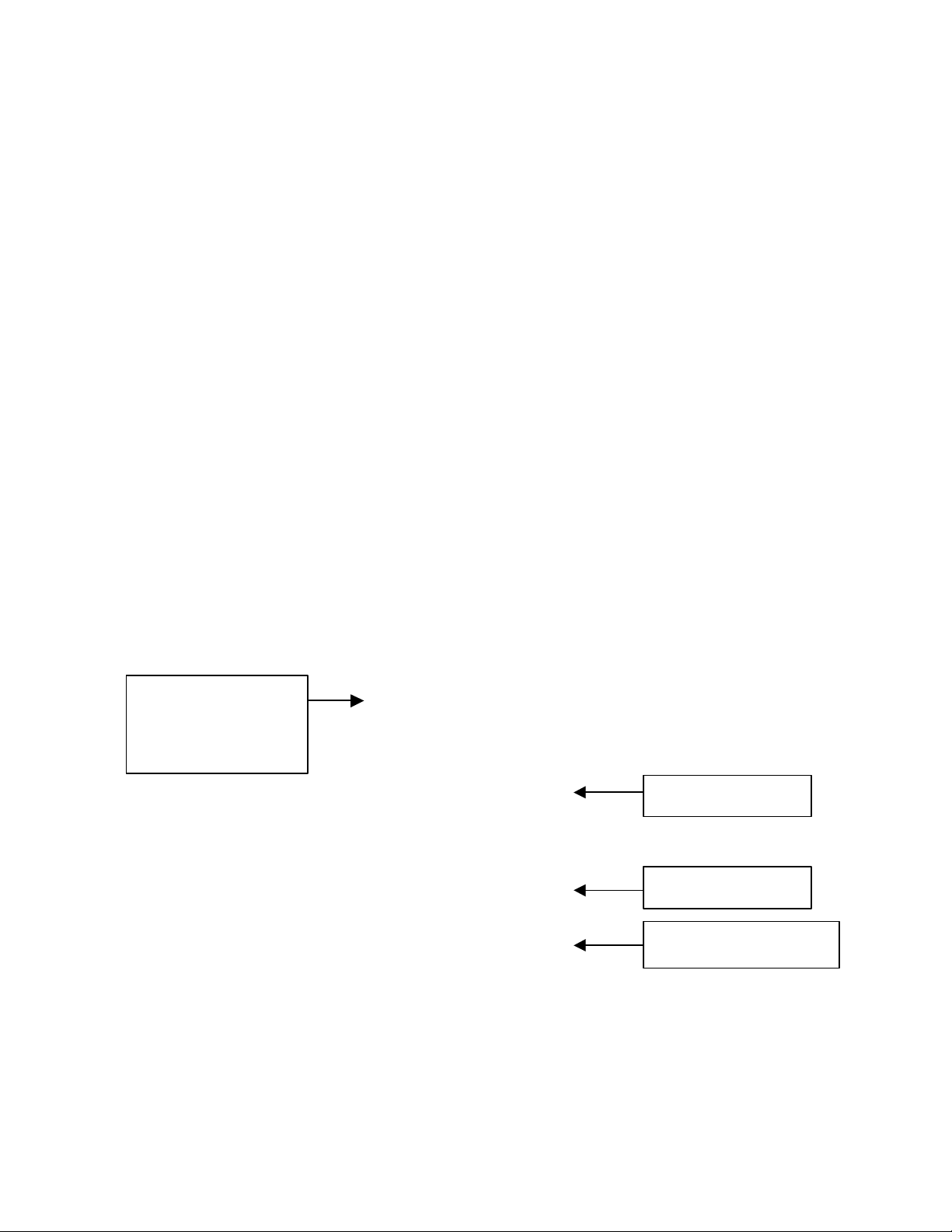
Start running the Pyramid 2012/Merlin programming software on your PC. From the
Data pull down menu, under the System Data screen, program the unit as shown the
figure below.
+-----------------------------+
¦ ¦
Vehicle # and Base # will
vary with your application.
Console needs to
match programming the
2016 Console Software.
From the Data pull down menu, select your Data Format in the Format Screen. There
are three signaling format choices. Chose the format to fit your application.
More programming instructions are available in the 2012/Merlin Service Manual.
¦ Vehicle #: 100 (000-999) ¦
¦ Base #: 1 (1-4) ¦
¦ ¦
¦ PTT Delay: 0.5 S (.1-2.5) ¦
¦ Retries: 3 (0-9) ¦
¦ ¦
¦ Trunking mobile Yes ¦
¦ Sequential Status No ¦
¦ ANI on mobile PTT No ¦
¦ Enable Time Stamp No ¦
¦ ¦
¦ COR Polarity High ¦
¦ On Air Polarity High ¦
¦ I/O Pin 9 Output Ch Cng ¦
¦ Method Cont. ¦
¦ ¦
+-----------------------------+
Set COR and On Air
Set I/O Pin 9 to Channel
Change, Method Continuous
3
Page 4
Programming the Kenwood TK-x80 Series Mobile
Program Com 2 as AUX Hoot/PTT
Ext. PTT /w Mic Mute = Yes
Data TX w/ QT/DQT = Yes
ARQ Mode = Disable
To begin programming your TK-x80 series mobile for use with the Pyramid
Communications Model 2012/Merlin mobile data system, you will need to first create a
new profile using your KPG-49D programming software.
Radio Format
When programming the radio select trunking or conventional, make sure that you set the
Radio Format correctly upon creation of your new profile. See figure below.
Select Trunking
or Conventional
Programming Optional Features
From the Edit pull down menu, select Optional Features. Depending on your
application, most of the parameters in the Optional Feature menu will be left at default.
Although this may be the case, in order to enable a data terminal interface you must
program Com 2 (Internal Port) as AUX Hook/PTT. This enables the external PTT from
the data terminal. See the figure below for more information.
While in the Optional Features screen, select Extended Function. Set as follows:
+------------------------------------------------------------------------------+
¦ Optional Features ¦
¦------------------------------------------------------------------------------¦
¦ System Name Text Size : [Off] ¦ T.O.T(Dispatch) : [ 60]s ¦
¦ Sub LCD Display : [None ] ¦ T.O.T(TEL) : [180]s ¦
¦ Conv. Busy LED : [Off] ¦ TX Inhibit Time : [5.0]s ¦
¦ Display Character : [Group Name] ¦ Transpond Delay Time : [ 3]s ¦
¦ Off Hook Decode : [Disable] ¦ System Search : [None ] ¦
¦ Off Hook Horn Alert : [Disable] ¦ Clear to Talk : [Yes] ¦
¦ Horn Alert Time : [ 4]s ¦ Free System Ring Back : [No ] ¦
¦ Radio Password : [ ] ¦ Battery Warning : [ -------] ¦
¦ Data Password : [ ] ¦ Timed Power Off : [Off] ¦
¦ Power On Text : [ ] ¦ Tone Feat ure... ¦
¦ Signalling : [OR ] ¦ ID... ¦
¦ Sel. Call Alert LED : [Yes] ¦ PTT Release Tone... ¦
¦ Encode Data Type : [Invert] ¦ Logic Signal... ¦
¦ Com 0(Mic. Jack) : [None ] ¦ Mode... ¦
¦ Com 1(Internal Port) : [None ] ¦ Emergency... ¦
¦ Com 2(Internal Port) : [Aux Hook/PTT] ¦ Extended Function... ¦
+------------------------------------------------------------------------------+
+--------------------------+
¦ Radio Format ¦
¦--------------------------¦
¦ 1. Conventional ¦
¦ 2. Trunking ¦
+--------------------------+
+----------------------------------+
¦ Extended Function ¦
¦----------------------------------¦
¦ Ext. PTT w/ Mic Mute : [Yes] ¦
¦ Data TX w/ QT/DQT : [Yes] ¦
¦ ARQ Mode : [Disable] ¦
+----------------------------------+
4
Page 5

Programming the Logic Signalling
Type to Active Hi
Signal to TOR
be set to None
voice and data. Data group must be last in list.
From the Optional Features screen, use your cursor to select Logic Signalling. In order
for the radio to provide proper signaling polarities to the 2012/Merlin and 2016 data
terminal interface on the KCT-19, it is necessary to program the Logic Signalling I/O as
shown in the figure below.
+---------------------------------------- +
¦ Logic Signal ¦
Set Squelch Logic
¦---------------------------------------- ¦
¦ Squelch Logic Type : [Active Hi ] ¦
¦ Squelch Logic Signal : [TOR] ¦
Set Squelch Logic
¦ Access Logic Type : [Active Low ] ¦
¦ Access Logic Signal : [Continuous] ¦
¦ Horn Alert Logic Signal : [Continuous] ¦
+---------------------------------------- +
Programming the Talk Group information for a 2012/Merlin MDT
When using the TK-x80 series radio in mobile operation along with a Pyramid
2012/Merlin, it is desirable to use a separate talk group for data aside from voice
communication. In order to do this, it is necessary to add a talk group for data to the
system. The figure below depicts a typical talk group configuration.
+------------------------------------------------------------------------------ +
¦ System No. : 1 Trunking Mode ¦
¦------------------------------------------------------------------------------ ¦
¦ Grp Option ¦
¦ Grp EncID DecID Grp-Name Call Pwr Transpond LOut Signal TA ¦
¦ 1 150 150 Voice Chan No *** No No None No ¦
¦ 2 151 151 Data Chan No *** No No None No ¦
¦ 3 ¦
¦ 4 ¦
¦ 5 ¦
¦ 6 ¦
¦ 7 ¦
¦ 8 ¦
¦ 9 ¦
¦ 10 ¦
+--------------------------------------------------------- ---------------------+
Separate Talk Group ID codes are used for
Option Signal should
5
Page 6

Defining a Talk Group for Data Use
System/Group for
There are two places in the system information screen that you have to define a talk
group as being a data talk group.
First, select the data talk group with your cursor, and press the F9 Key. This will bring
up the System Data screen as shown in the figure below. Program the Data
System/Group for the system and group number in your radio. This value will vary
based on how many systems and groups are programmed into your radio.
+------------------------------------- +
¦ System Data ¦
¦------------------------------------- ¦
¦ System Name : [ 1 ] ¦
¦ System Lockout : [***] ¦
¦ Scan Weight : [*] ¦
¦ Auto TEL Search : [No ] ¦
¦ TA Busy Ch LOut : [No ] ¦
¦ Wide/Narrow : [******] ¦
¦ Fix ID 1st 2nd ¦
¦ ID : [ ] [ ] ¦
¦ Call Indicator : [***] [***] ¦
¦ Horn Alert : [***] [***] ¦
¦ Opt Signalling : [****] [****] ¦
¦ Block ID's Start Stop ¦
¦ Telephone : [ - ] ¦
Program the
appropriate
the data group
¦ TX Inhibit : [ - ] ¦
¦ Decode : [ - ] ¦
¦ Data System/Group : [ 1 - 2 ] ¦
¦ Data Delay Ti me : [ 15]ms ¦
+------------------------------------- +
Second, you must define the talk group as data in the group information screen. To
access the group information screen, select the data talk group with your cursor and press
the F10 key. The figure below shows how to define the talk group as data.
+----------------------------------+
¦ Group Data 2 ¦
¦----------------------------------¦
¦ Encode ID : [151] ¦
¦ Decode ID : [151] ¦
¦ Group Name : [Data Chan ] ¦
¦ TX Power : [****] ¦
¦ Call Indicator : [No ] ¦
¦ Horn Alert : [No ] ¦
¦ Option Signalling : [None] ¦
¦ Group-Lockout : [No ] ¦
¦ Transpond : [No ] ¦
¦ Talk Around : [No ] ¦
¦ Compander : [***] ¦
¦ Home Group : [***] ¦
¦ PTT ID : [Off] ¦
¦ Data : [Yes] ¦
+----------------------------------+
6
Page 7

Programming the Pyramid 2016
Air Polarity to High
Note:
Programming of the Pyramid 2016 base modem is done through the console interface.
Typically, the parameters are set in the Pyramid Console software, and then automatically
sent to the 2016. If you are using Manning NavComp Inc’s RasTrac MX software for
you console interface, all configuration is done within the RasTrac I/O processor that
runs on your PC simultaneously with the RasTrac mapping software. Consult your
RasTrac manual for more information.
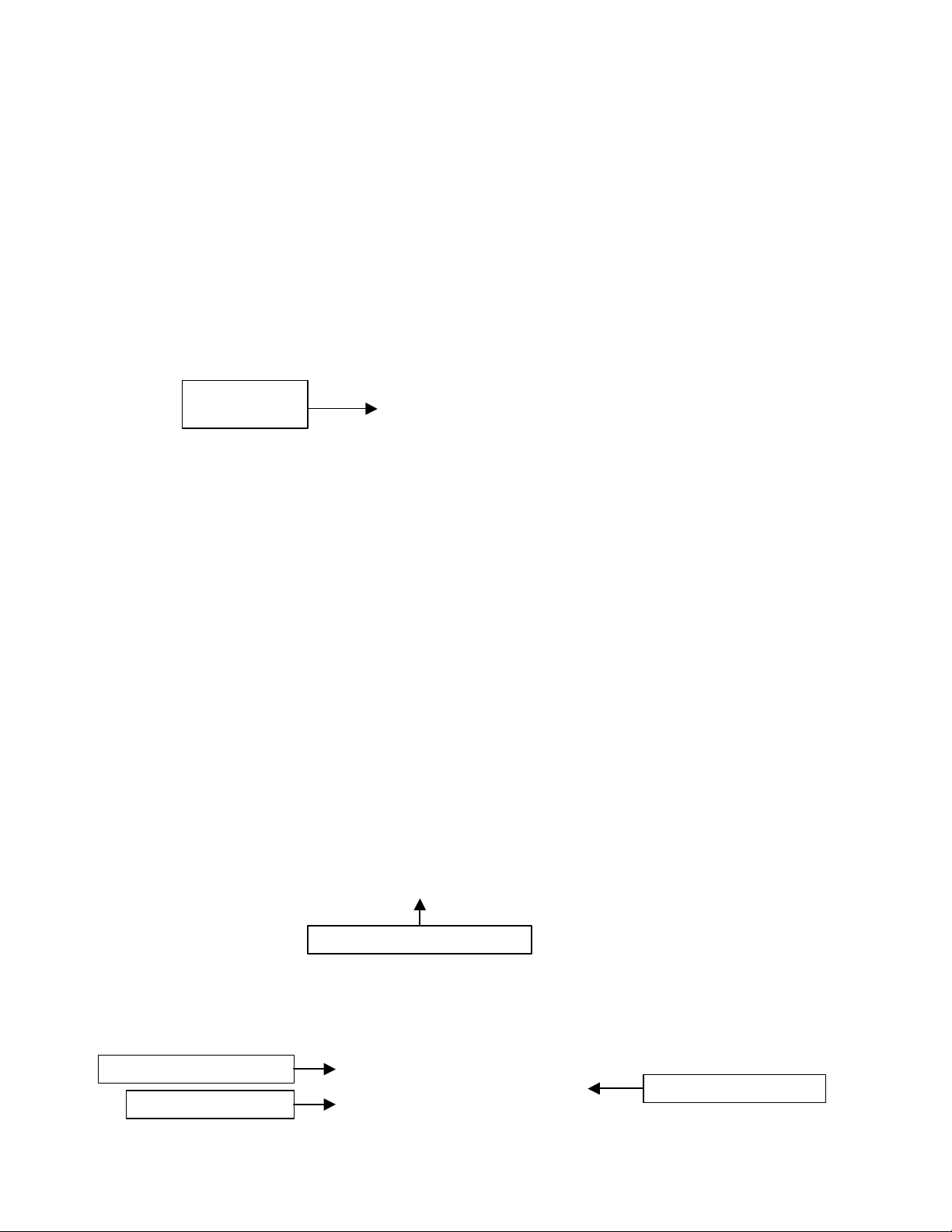
The figure below shows how a typical Pyramid Console software would be set up when
connected to a 2016 and TK-x80 series radio. To access the Modem Parameters menu,
select Configure from the pull down menu.
+------- Modem Parameters -----+
Set PTT Delay to
Trunking if you are on a
Console and Speed vary
on your application
Console needs to
match programming the
2012.
See the Pyramid 2016 service manual for further Pyramid Console software information.
¦ ¦
¦ PTT Delay: Trunking ¦
¦ COR Polarity: Active Hi ¦
¦ On-Air Polarity: Active Hi ¦
¦ Console: 1 ¦
¦ Speed: 1200 ¦
+------------------------------+
Set COR and On-
7
Page 8

Programming the Pyramid 2016 (Continued)
Set COR and PTT to HI
0-Trunking if applicable.
Speed will vary
Note:
needs to match
Note:
Console
needs to match
Set COR and PTT to HI
0.5 Seconds. This is the delay
king
Select Trunking if
The figures below shows how a typical RasTrac I/O processor will be set up when
connected to a 2016 and TK-x80 series radio. To access the I/O configuration, select the
Edit pull down menu from the RasTrac I/O Processor. From the Input/Output
Configuration screen, select the Protocol to be PYRAMID. Then click Properties to
configure the 2016.
Console and
with your
Set PTT Delay to
application.
programming
the 2012.
Console
Depending on the version of the Rastrac IOP you are using, your IOP setup screen may
look like either of these examples.
Set PTT Delay to
after the handshake if trun
is selected. If using
conventional, this is the PTT
lead in delay before sending
data.
Console and
Speed will vary
with your
application.
you are using a
Trunking Radio
programming
the 2012.
8
Page 9

Grey Wi
re to Pin 15
Understanding Base Channel Change
In order to understand the operation of data channel change you have to realize that the
mobile units are using a dedicated PassPort/LTR ID code for data and a separate
PassPort/LTR ID code(s) for voice communication. When the MDT sends a message, the
mobile radio is switched to the defined data PassPort/LTR ID; after the transmission is
complete, the radio reverts back to the voice ID code. The 2016 base unit receives and
responds on the data PassPort/LTR ID code.
A problem arises when the dispatcher needs to send an outbound message (e.g. GPS Poll,
Text Message, Horn Honk, etc.). At most times, the mobile units are idle and therefore
on the voice PassPort/LTR ID code. When a message from the base is sent, it is sent on
the data PassPort/LTR ID code, thus the targeted mobile unit does not receive the
command from the dispatcher because it is listening on a different PassPort/LTR ID code.
To overcome this obstacle, the 2016 can be configured to change to the voice
PassPort/LTR ID code when sending outbound, base originated messages. As with all
base modem installations, a dedicated radio is required for the 2016 base modem.
Configuring your 2016 for Voice Channel Change
There is a simple wiring harness change is needed to enable the 2016 to activate the
channel change line out of the 2016 Base Modem. From the 2016 wiring harness,
connect the Teal wire ground. This activates the Grey wire as the Voice Channel Select
line.
Crimp a Molex pin onto the Grey wire from the Pyramid Communications Model 2016
wiring harness and connect to the Kenwood KCT-19 Pin 15. See figure below of Molex
pin layout.
9
Page 10

Programming the Kenwood TK-x80 Series Base
Program Com 2 as AUX Hoot/PTT
Ext. PTT /w Mic Mute = Yes
Data TX w/ QT/DQT = Yes
ARQ Mode = Disable
To begin programming your TK-x80 series mobile for use with the Pyramid
Communications Model 2016 base modem, you will need to first create a new profile
using your KPG-49D programming software.
Radio Format
When programming the radio select trunking or conventional, make sure that you set the
Radio Format correctly upon creation of your new profile. See figure below.
Select Trunking
or Conventional
Programming Optional Features
From the Edit pull down menu, select Optional Features. Depending on your
application, most of the parameters in the Optional Feature menu will be left at default.
Although this may be the case, in order to enable a data terminal interface you must
program Com 2 (Internal Port) as AUX Hook/PTT. This enables the external PTT from
the data terminal. See the figure below for more information.
While in the Optional Features screen, select Extended Function. Set as follows:
+--------------------------------------------------------------- ---------------+
¦ Optional Features ¦
¦------------------------------------------------------------------------------¦
¦ System Name Text Size : [Off] ¦ T.O.T(Dispatch) : [ 60]s ¦
¦ Sub LCD Display : [None ] ¦ T.O.T(TEL) : [180]s ¦
¦ Conv. Busy LED : [Off] ¦ TX Inhibit Time : [5.0]s ¦
¦ Display Character : [Group Name] ¦ Transpond Delay Time : [ 3]s ¦
¦ Off Hook Decode : [Disable] ¦ System Search : [None ] ¦
¦ Off Hook Horn Alert : [Disable] ¦ Clear to Talk : [Yes] ¦
¦ Horn Alert Time : [ 4]s ¦ Free System Ring Back : [No ] ¦
¦ Radio Password : [ ] ¦ Battery Warning : [-------] ¦
¦ Data Password : [ ] ¦ Timed Power Off : [Off] ¦
¦ Power On Text : [ ] ¦ Tone Feature... ¦
¦ Signalling : [OR ] ¦ ID... ¦
¦ Sel. Call Alert LED : [Yes] ¦ PTT Release Tone... ¦
¦ Encode Data Type : [Invert] ¦ Logic Signal... ¦
¦ Com 0(Mic. Jack) : [None ] ¦ Mode. .. ¦
¦ Com 1(Internal Port) : [None ] ¦ Emergency... ¦
¦ Com 2(Internal Port) : [Aux Hook/PTT] ¦ Extended Function... ¦
+----------------------------------------------------------- -------------------+
+--------------------------+
¦ Radio Format ¦
¦--------------------------¦
¦ 1. Conventional ¦
¦ 2. Trunking ¦
+--------------------------+
+----------------------------------+
¦ Extended Function ¦
¦----------------------------------¦
¦ Ext. PTT w/ Mic Mute : [Yes] ¦
¦ Data TX w/ QT/DQT : [Yes] ¦
¦ ARQ Mode : [Disable] ¦
+----------------------------------+
10
Page 11

Programming the Logic Signalling
Type to Active Hi
Signal t
o TOR
From the Optional Features screen, use your cursor to select Logic Signalling. In order
for the radio to provide proper signaling polarities to the 2012/Merlin and 2016 data
terminal interface on the KCT-19, it is necessary to program the Logic Signalling I/O as
shown in the figure below.
+---------------------------------------- +
¦ Logic Signal ¦
Set Squelch Logic
¦---------------------------------------- ¦
¦ Squelch Logic Type : [Active Hi ] ¦
¦ Squelch Logic Signal : [TOR] ¦
Set Squelch Logic
¦ Access Logic Type : [Active Low] ¦
¦ Access Logic Signal : [Continuous] ¦
¦ Horn Alert Logic Signal : [Continuous] ¦
+---------------------------------------- +
Programming the Talk Group information for a 2016 Base Modem
The following is an example of how to setup your Kenwood 80 series radio for voice
channel change on base initiated messages. Group 1 is the data channel. This is the
channel that all messages from mobile units will be received on. Group 2 is the channel
that all of the voice traffic will be occurring.
When the 2016 base modem keys up the base radio to send a outbound message, the
radio will be switched to Group 2; after the transmission it will immediately revert back
to Group 1 to listen for messages from any MDT unit.
Follow the screen shots below to program the Kenwood radio for group change.
Add data group and voice group to list.
+------------------------------------------------------------------------------+
¦ System No. : 1 Trunking Mode ¦
¦------------------------------------------------------------------------------¦
¦ Grp Option ¦
¦ Grp EncID DecID Grp-Name Call Pwr Transpond LOut Signal TA ¦
¦ 1 1 1 Group 1 No Hi No No None No ¦
¦ 2 2 2 Group 2 No Hi No No None No ¦
¦ 3 ¦
¦ 4 ¦
¦ 5 ¦
¦ 6 ¦
¦ 7 ¦
¦ 8 ¦
¦ 9 ¦
¦ 10 ¦
+--------------------------------------------------------------- ---------------+
Add the Data and voice
group to the system.
11
Page 12

Select the voice group and press F9 to setup System Data.
Set Data System/Group to the
Voice System/Group number.
+-------------------------------------+
¦ System Data ¦
¦-------------------------------------¦
¦ System Name : [ ] ¦
¦ System Lockout : [***] ¦
¦ Scan Weight : [*] ¦
¦ Auto TEL Search : [No ] ¦
¦ TA Busy Ch LOut : [No ] ¦
¦ Wide/Narrow : [Wide ] ¦
¦ Fix ID 1st 2nd ¦
¦ ID : [ ] [ ] ¦
¦ Call Indicator : [***] [***] ¦
¦ Horn Alert : [***] [***] ¦
¦ Opt Signalling : [****] [****] ¦
¦ Block ID's Start Stop ¦
¦ Telephone : [ - ] ¦
¦ TX Inhibit : [ - ] ¦
¦ Decode : [ - ] ¦
¦ Data System/Group : [ 1 - 2 ] ¦
¦ Data Delay Time : [ 15]ms ¦
+-------------------------------------+
Select the voice group and press F10 to setup Group Data.
+----------------------------------+
¦ Group Data 2 ¦
¦----------------------------------¦
¦ Encode ID : [ 2 ] ¦
¦ Decode ID : [ 2 ] ¦
¦ Group Name : [Voice ] ¦
¦ TX Power : [High] ¦
¦ Call Indicator : [No ] ¦
¦ Horn Alert : [No ] ¦
¦ Option Signalling : [None] ¦
¦ Group-Lockout : [No ] ¦
¦ Transpond : [No ] ¦
¦ Talk Around : [No ] ¦
¦ Compander : [***] ¦
¦ Home Group : [***] ¦
¦ PTT ID : [Off] ¦
¦ Data : [Yes] ¦
+----------------------------------+
Data = Yes on voice group
From the Edit pull down menu, select Scan Information. Set Dwell Time to 0 Seconds.
+----------------------------------------------+
¦ Scan Information ¦
¦----------------------------------------------¦
¦ Scan Type : [Fix System Scan ] ¦
¦ Revert Sys Type : [Last Called] ¦
¦ Dropout Delay Time : [ 3]s ¦
¦ Dwell Time : [ 0]s ¦
¦ Look Back Time A : [0.50]s ¦
¦ Look Back Time B : [2.00]s ¦
¦ Revert Grp Display : [Off] ¦
¦ Off Hook Scan : [Disable] ¦
+----------------------------------------------+
Set Dwell Time to 0 Sec.
12
Page 13

Wiring the Pyramid to the Kenwood TK-x80
Once all of the programming has been completed, it is time to connect the units to the
radios.
Connecting the 2012/Merlin MDT to the TK-x80 radio
The following are the pin outs for the KCT-19 option connector of the TK-x80 series
radios. These connections must be made to the corresponding color-coded cable from the
2012/Merlin. Install the KCT-19 "E" plug into CN-2.
Connections: 2012/Merlin Function Radio
Black/Shield Ground KCT-19 Pin 6
White Tx Audio Out KCT-19 Pin 9
Blue On-Air Detect KCT-19 Pin 5
Green PTT Out KCT-19 Pin 8
Red Switched B+ KCT-19 Pin 7
Yellow Rx Audio In KCT-19 Pin 4
Violet COR KCT-19 Pin 11
Brown Audio Mute Out N/C
Grey Mic Mute/Channel Select KCT-19 Pin 15
Jumper Settings in the 2012/Merlin
J1 [Out] Tx audio level
J2 [Out] Local PTT Loop
Connecting the 2016 base to the TK-x80 radio
The following are the pin outs for the KCT-19 option connector of the TK-x80 series
radios. These connections must be made to the corresponding color-coded cable from the
2016. Install the KCT-19 "E" plug into CN-2.
Connections: 2016 Function Radio
Black/Shield Ground KCT-19 Pin 6
White Tx Audio Out KCT-19 Pin 9
Blue On-Air Detect KCT-19 Pin 5
Green PTT Out KCT-19 Pin 8
Red Switched B+ KCT-19 Pin 7
Yellow Rx Audio In KCT-19 Pin 4
Violet COR KCT-19 Pin 11
Brown Audio Mute Out N/C
Grey Mic Mute/Channel Select KCT-19 Pin 15
Teal Base Chan. Chg. Enable Ground
13
Page 14

Supporting the Kenwood KDS-100 /w Merlin AVL
Modifications To Kenwood TK-x80 Mobile Radio
When you are installing both a KDS-200 Data Head and a Merlin 2017 AVL unit onto
the same radio, some modifications have to be made to get all proper signals to the KCT19 connector. When you are connecting a KDS-100 without a Merlin AVL unit to a
radio, you normally use a KCT-34 option connector. In this case you will be using a
KCT-19 option connector kit. You will have to perform the following modifications to
the KCT-19/Radio to connect all required signals to the KCT-19 output:
1) Remove the Red wire from pin 2 of CN1 and solder this wire to pin 3 of CN2 in
the TK-x80 radio.
2) Remove the Orange wire from pin 3 of CN1 and solder this wire to pin 2 of CN2
in the TK-x80 radio.
3) Be sure to install the “E” lead of the KCT-19 into CN-4 of the TK-x80 radio.
Once the above modifications are complete, you will have all necessary signals available
for both the KDS-100 and the Merlin AVL at the KCT-19 15 pin connector. From this
point you will need to install the 7525-10-1044 “Y” cable to split the necessary signals
between the KDS-100 and the Merlin AVL. Plug the 7525-10-1044 “Y” cable into the
KCT-19 from the radio.
KDS-100 Modifications
The KDS-100 connects to the KDS-100 side of this 7525-10-1044 “Y” cable. Your
KDS-100 will need to be programmed for “PC” mode.
Merlin AVL Modifications
The Merlin connects to the 2017 Merlin side of the 7525-10-1044 “Y” cable. No changes
are made to the interface of the Merlin AVL to the KCT-19 vs. the interface of a Merlin
AVL to a 7525-10-1044 “Y” cable.
1) Rather then inserting the Grey wire from the Merlin AVL into pin 15 of the
Kenwood Connector, Insert the Grey wire from the Merlin AVL into pin 1 of the
Kenwood Connector.
14
Page 15

Modifications To Kenwood TK-x80 Base Radio
When you are installing both a 2016 Base Modem and the interface to the PC for
FleetSync Data, some modifications have to be made to get all proper signals to the KCT19 connector. You will have to perform the following modification to the KCT-19/Radio
to connect all required signals to the KCT-19 output:
1) Remove the Red wire from pin 2 of CN1 and solder this wire to pin 3 of CN2 in
the TK-x80 radio.
2) Be sure to install the “E” lead of the KCT-19 into CN-4 of the TK-x80 radio.
Once the above modifications are complete, you will have all necessary signals available
for both the 2016 Base Modem.
Note: With this modification, instead of inserting the Grey wire from the Merlin AVL into
pin 15 of the Kenwood Connector, Insert the Grey wire from the Merlin AVL into pin 1 of
the Kenwood Connector.
From this point you will be feeding your PC with two separate serial data signals, one
from the 2016 base modem and one from the PC output of the TK-x80 radio, providing
the FleetSync data to the PC.
15
 Loading...