

Page 1

m
CONTROL AMPLIFIER
KC-993
INSTRUCTION MANUAL
KENWOOD CORPORATION
B60-1054-00 di) (K. P, M,X,Y)
Page 2
Introduction
Your choice of this product indicates that you are a devotee
to exceilence in sound reproduction.
We appreciate your patronage and take pride in the long tradi
tion of quality components that our company represents.
So that you can get the most ou"t of your unit, we suggest that
you take the time to read through this manual before you hook
up and operate your system. This will acquaint you with oper
ating features and system-connection considerations, so that
your listening pleasure will be enhanced right from the start.
You will notice that in all aspects of planning, engineering,
styling, operating convenience and adaptability we have sought
to anticipate your needs and desires.
Keep this manual handy for future reference.
For your records
Record the serial number, found on the back of the unit, in
the spaces designated on the warranty card, and in the space
provided below. Refer to the mode! and serial numbers
whenever you cal! upon your dealer for information or service
on this product.
Model
_______________
Unpacking
Unpack the unit carefully and make sure that all accessories
are put aside so they will not be lost.
Examine the unit for any possibility of shipping damage. If
your unit is damaged or fails to operate, notify your dealer
immediately, if your unit was shipped to you directly, notify
the shipping company without delay. Only the consignee (the
person or company receiving the unit) can file a claim against
the carrier for shipping damage.
We recommend that you retain the original carton and pack
ing materials for use should you transport or ship the unit in
the future.
Serial Number
_____________________
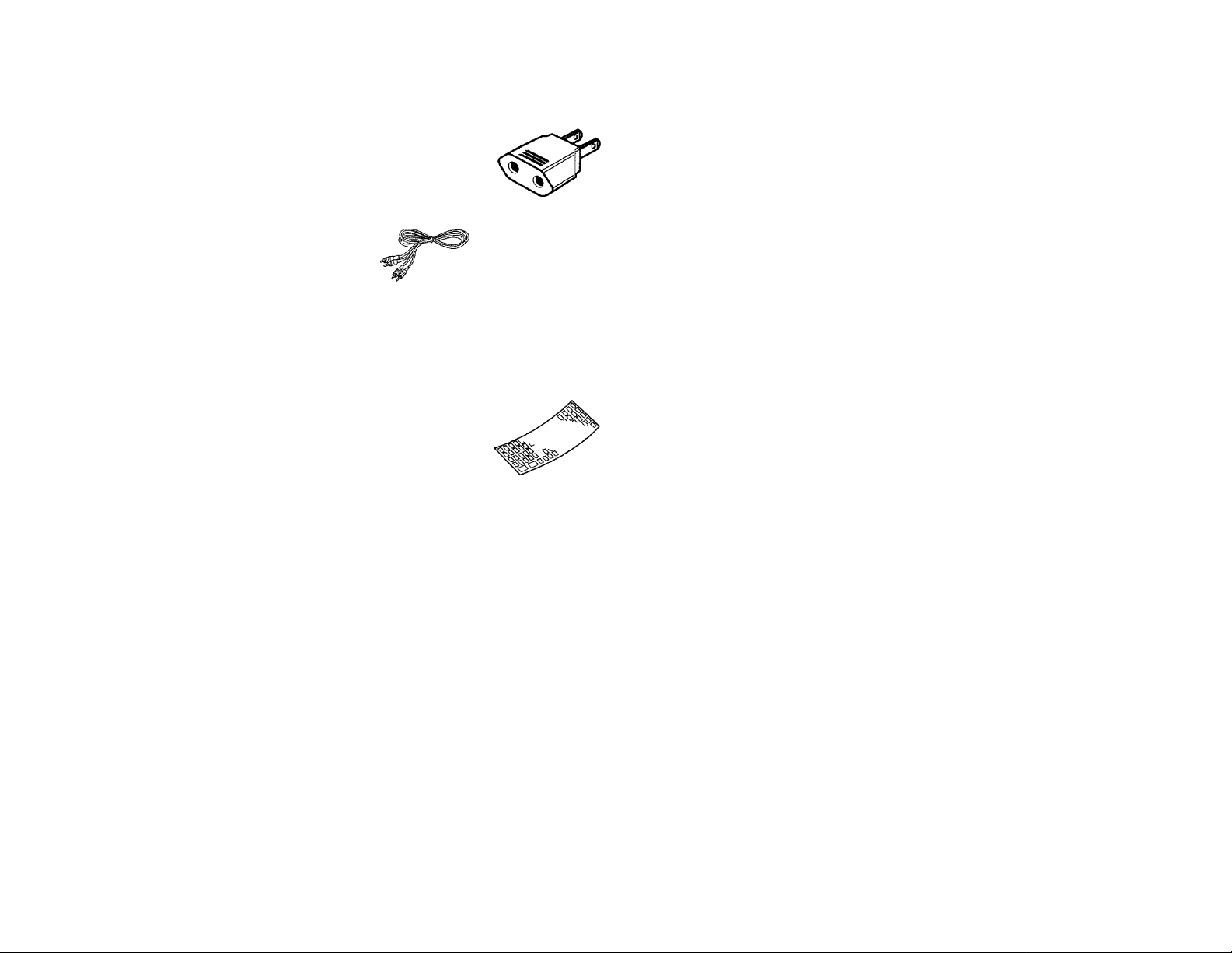
Accessories
• AC plug adaptor
(Except for some areas)
For the unit with a European
AC plug in areas other than
Europe.
Audio cord ..
Remote control unit...... 1 • Batteries (R03/AAA).... 2
....
..............
1
Overlay sheet ...............1
Contents
Introduction ..........................................
A Before applying power
A Safety precautions
A IMPORTANT SAFEGUARDS
Controls and indicators
System connections
System control operation _________________________
.....................
........................................................
...........................................
Caution: Read the pages marked A carefully to ensure safe operation.
...........
.....................................................
................
........................................
....................2
......................
.........
.........
...4
3
Operation for components connected
3
6
7
8
to the TAPE 2/ADAPTOR jacks...................................13
Graphic equalizer operation
Remote control operation ....
In case of difficulty
A Specifications
...........................................................
..............................
............................
................................
................................
.........................
..................
.............14
...................................
............17
23
..10operating instructions
22
Page 3
Before applying power
Caution: Read this page carefully to ensure safe operation.
A
For the U.S.A. and Canada
Units shipped to the U.S.A. and Canada are designed for
operation on 120 volts AC only.
CAUTION; TO PREVENT ELECTRIC SHOCK DO NOT USE
THE AC PLUG WITH AN EXTENSION CORD, RECEPTACLE OR
OTHER OUTLET UNLESS THE BLADES CAN BE FULLY
INSERTED TO PREVENT BLADE EXPOSURE.
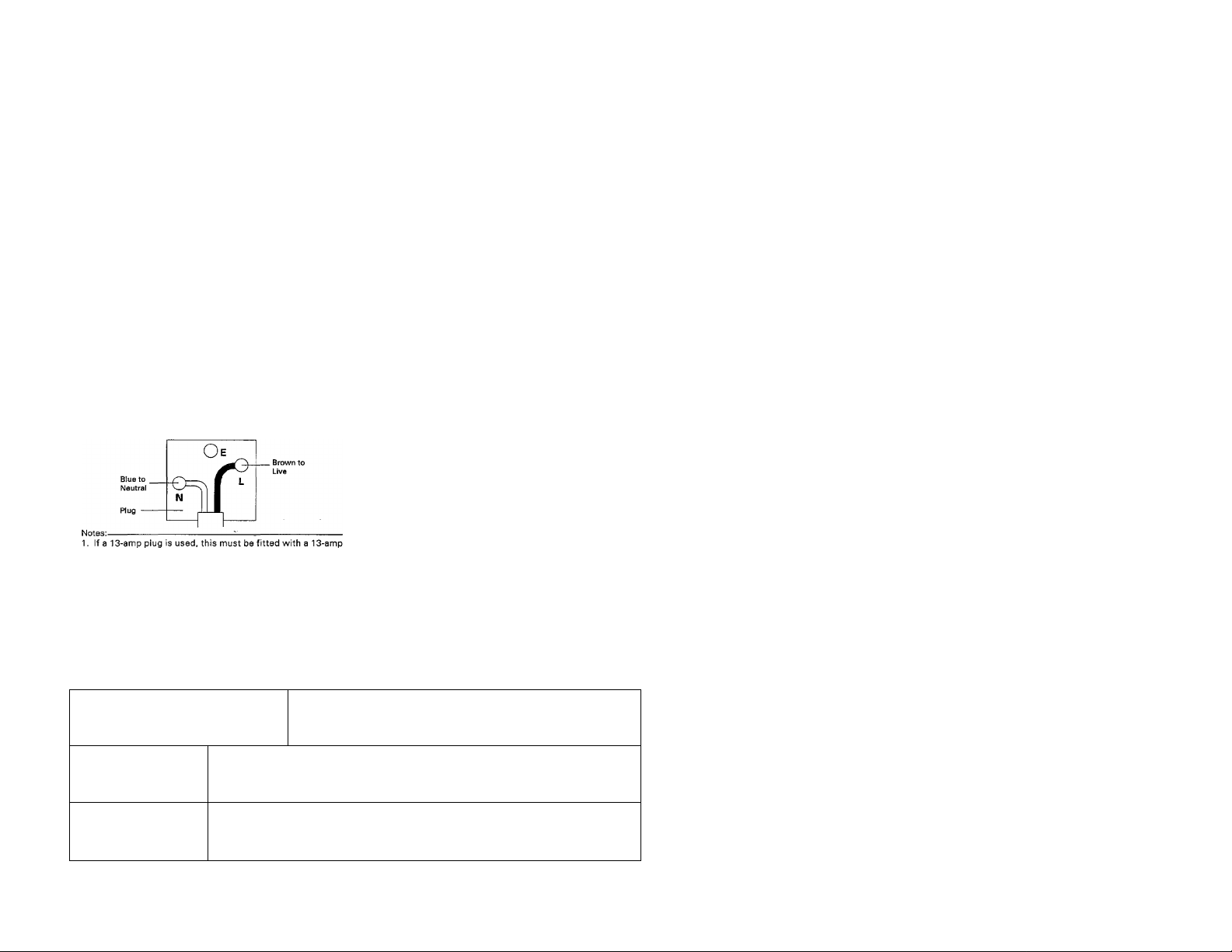
For the United Kingdom
Units shipped to the U.K. are designed for operation on 240
volts AC only.
The mains plug must be removed from the wall socket prior to
any internal examination.
The wires in this mains lead are coloured in accordance with the
following code;
Blue
.........................
Brown
................—_________________
The wires in this mains lead must be connected to the terminals
in the plug as follows:
Wire colour Plug terminal marking
Blue
....................................................
Brown
..........................................
fuse.
2. If a 3-pin plug with earthing contact is used, no wire must be
connected to the E terminal.
Important!
Important I
—...............
_____
Neutral
Li-\te
N or Black
........ L or Red
For Australia and Europe
Units shipped to Australia are designed for operation on 240 V AC
only.
Units shipped to Europe are designed for operation on 230 V AC only.
For other countries
Units shipped to countriesother than the above countries are equipped
with an AC voltage selector switch on the rear panel. Refer to the
following paragraph for the proper setting of this switch.
AC voltage selection
This unit operates on 110 -120 or 220 - 240 volts AC, The AC voltage
selector switch Type A or Type B on the rear panel is set to the
voltage that prevails in the area to which the unit is shipped. Before
connecting the power cord to your AC outlet, make sure that the
setting position of this switch matches your line voltage. If not it
must be set to your voltage in accordance with the following
direction.
Type A
TypeB
AC НО
ШУ-
Move switch lever to match your line voltage with
a small screwdriver or other pointed tool.
Our warranty does not cover damage caused by excessive line
voltage due to improper setting of the AC voltage selector switch.
importanti
Important!
AC voltage selector switch
AC110" ■
120 V~
AC 220240 V-
AC220V- AC230 - 240V-
Safety precautions
WARNING; TO PREVENT FIRE OR ELECTRIC SHOCK, DO NOT EXPOSE THIS APPLIANCE
TO RAIN OR MOISTURE.
A
A
CAUTION: TO REDUCE THE RISK OF ELECTRIC SHOCK, DO NOT REMOVE
COVER (OR BACK). NO USER-SERVICEABLE PARTS INSIDE, REFER SER
VICING TO QUALIFIED SERVICE PERSONNEL.
THE LIGHTNING FLASH WITH ARROWHEAD SYMBOL. WITHIN AN EQUILATERAL TRIANGLE,
IS INTENDED TO ALERT THE USER TO THE PRESENCE OF UNINSULATED "DANGEROUS VOL
TAGE" WITHIN THE PRODUCT'S ENCLOSURE THAT MAY BE OF SUFFICIENT MAGNITUDE
TO CONSTITUTE A RISK OF ELECTRIC SHOCK TO PERSONS.
THE EXCLAMATION POINT WITHIN AN EQUILATERAL TRIANGLE IS INTENDED TO ALERT THE
USER TO THE PRESENCE OF IMPORTANT OPERATING AND MAINTENANCE (SERVICING) IN
STRUCTIONS IN THE LITERATURE ACCOMPANYING THE APPLIANCE.
KC-993 (En) 3
Page 4
IMPORTANT SAFEGUARDS
A Caution: Read this page carefully to ensure safe operation.
Please read all of the safety and operating instructions
before operating this unit. For best results, follow all
warnings placed on the unit and adhere to the operating
and use instructions. These safety and operating
instructions should be retained for future reference.
1. Power sources - The unit should be connected to
a power supply only of the type described In the
operating instructions or as marked on the
appliance.
2. Power-cord protection - Power-supply cords
should be routed so that they are not likely to be
walked on or pinched by Items placed upon or
against them, pay particular attention to cords at
plugs, convenience receptacles, and the point
where they exit from the unit.
Never pull or stretch
the cord.
3. Grounding or polarization - The precautions
should be taken so that the grounding or polarization
means of this unit is not defeated.
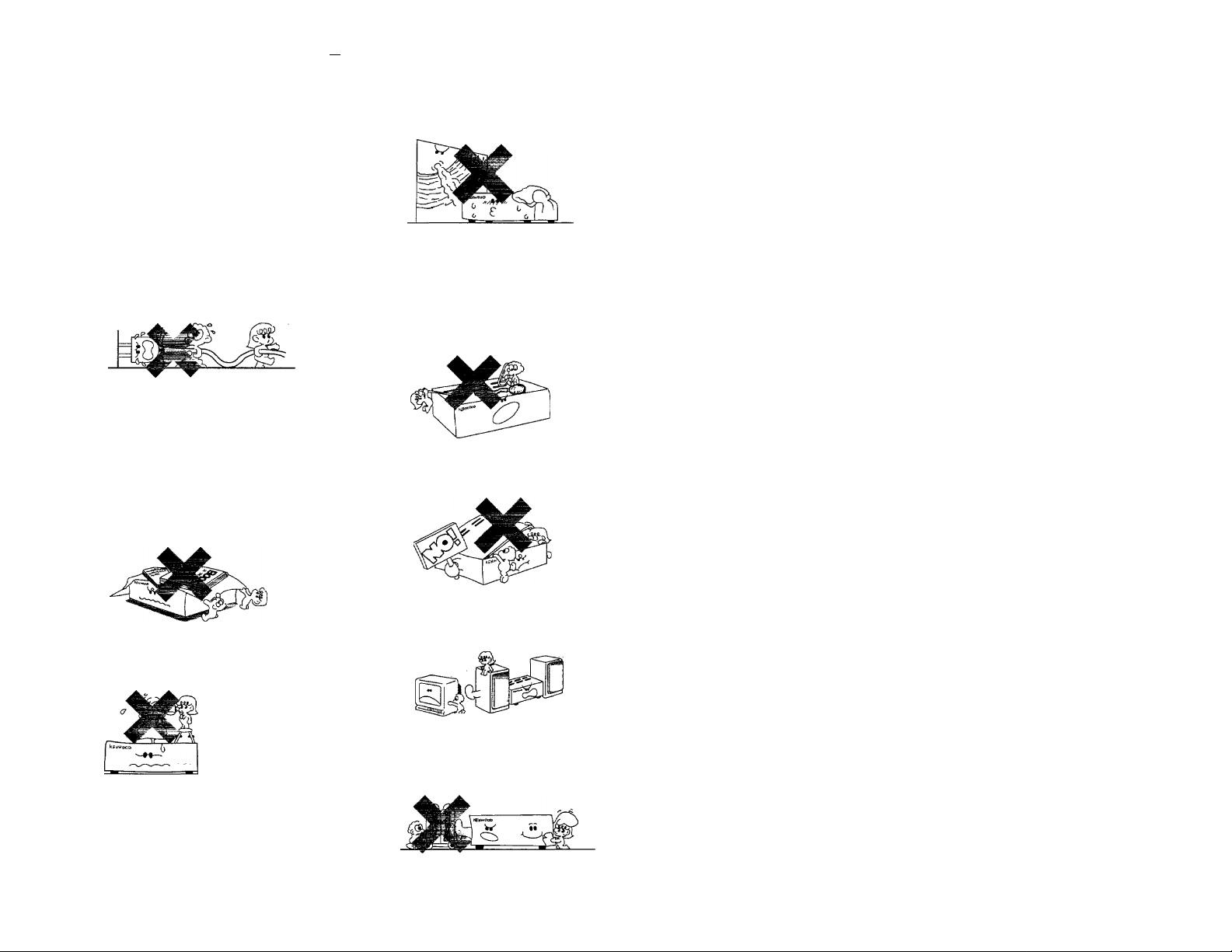
4. Ventilation - The unit should be situated so that
its location or positibri^does not interfere with its
proper ventilation.
To maintain good ventilation, do not put records or
a table-cloth on the unit. Place the unit at least 10
cm away from the walls.
Do not use the unit on a bed, sofa, rug or similar
surface that may block the ventilation openings.
7.Heat - The unit should be situated away from heat
sources such as radiators, heat registers, stoves,
or other units (including amplifiers) that produce
heat.
Electric shock - Care should be taken so that
objects do not fail and liquid is not spilled into the
enclosure through openings. If a metal object,
such as a hair pin or a needle, comes into contact
with the inside of this unit, a dangerous electric
shock may result. For families with children, never
permit children to put anything, especially metal,
inside this unit.
9. Enclosure removal - Never remove the enclosure.
If the internal parts are touched accidentally, a
serious electric shock might occur.
Water and moisture-The unit should not be used
nearwater-for example, neara bathtub, washbowl,
kitchen sink, laundry tub, in a wet basement, or
near a swimming pool, etc.
6. Temperature - The unit may not function properly
if used at extremely low, or freezing temperatures.
The ideal ambient temperature is above +5°C
(41°F).
10.Magnetic fields- Keep the unit away from sources
of magnetic fields such as TV sets, speaker
systems, radios, motorized toys or magnetized
objects.
11.Cleaning - Do not use volatile solvents such as
alcohol, paint thinner, gasoline, or benzine, etc. to
clean the cabinet. Use a clean dry cloth.
Page 5
A Caution : Read this page carefully to ensure safe operation.
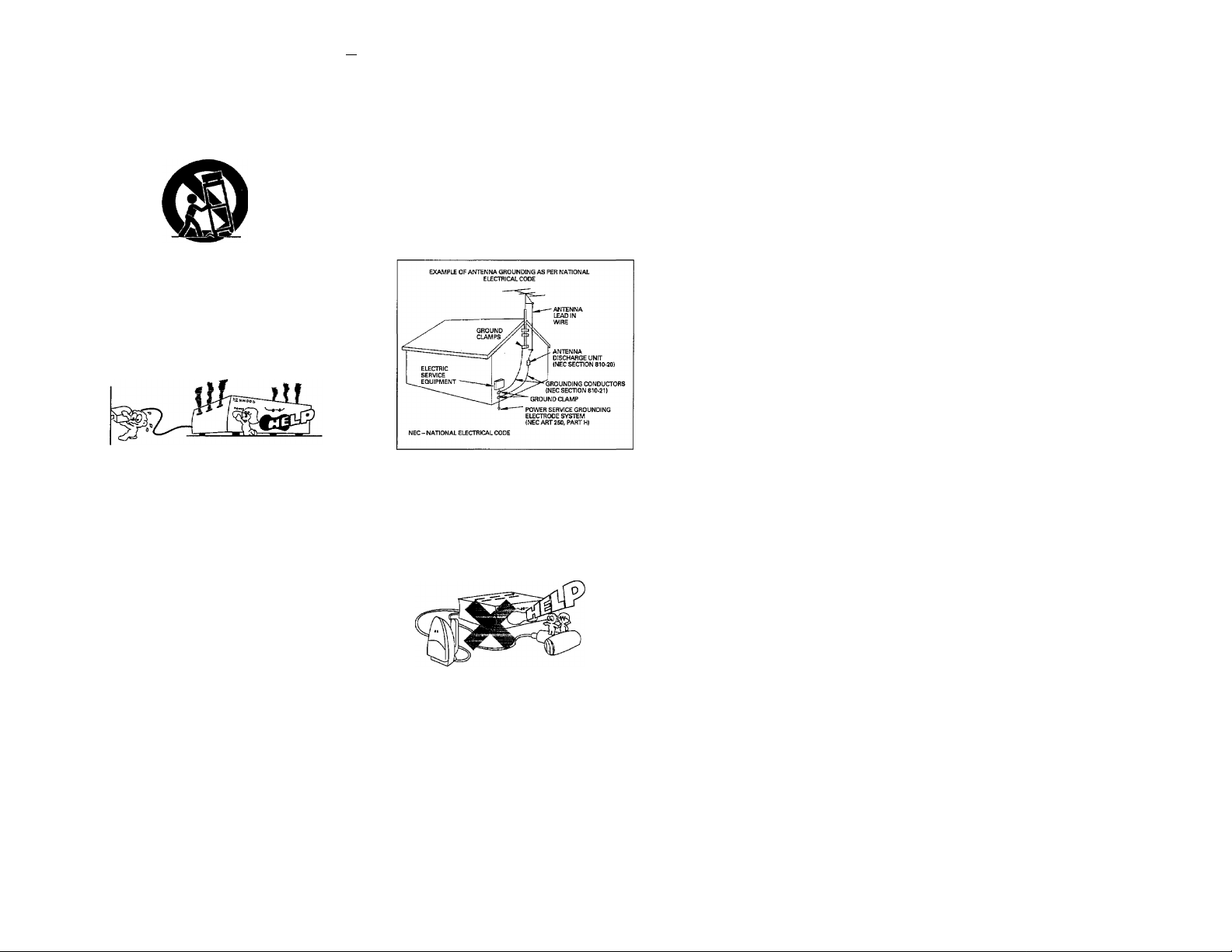
12.Carts and stands - An appliance and cart
combination should be moved with care. Quick
stops, excessive force, and uneven surfaces may
cause the appliance and cart combination to
overturn.
13. Nonuse periods ~ The power cord of the unit
should be unplugged from the outlet when left un
used for a long period of time.
14. Abnormal smell - If an abnormal smell or smoke
is detected, immediately turn the power OFF and
puli out the power cord. Contact your dealer or
nearest service center.
POWER OFF!
15.Damage requiring service - The unit should be
serviced by qualified service personnel when:
A. The power-supply cord or the plug has been
damaged; or
B. Objects have fallen, or liquid has been spilled
into the unit; or
C. The unit has been exposed to rain; or
D. The unit does not appear to operate normally or
exhibits a marked change in performance; or
E. The unit has been dropped, or the enclosure
damaged.
IG.Servicing - The user should not attempt to
service the unit beyond that described in the
operating instructions. All other servicing should
be referred to qualified service personnel.
17.Outdoor antenna grounding - If an outside an
tenna is connected to the receiver, be sure the an
tenna system is grounded so as to provide some
protection against voltage surges and built up static
charges. Section 810 of the National Electrical
Code, ANSI/NFPA 70, provides information with
respect to proper grounding of the mast and
supporting structure, grounding of the lead-in wire
to an antenna discharge unit, size of grounding
conductors, location of antenna-discharge unit,
connection to grounding electrodes, and
requirements for the grounding electrode. See
Figure.
18. Power lines - An outdoor antenna should be lo
cated away from power lines.
19. AC outlets - Do not connect other audio
equipment with a power consumption larger than
that specified to the AC outlet on the rear panel.
Never connect other electrical units, such as an
iron or toaster, to it to prevent fire or electric
shock.
Notes:
1. Item 3 is not required except for grounded or polarized equipment.
2. Item 17 and 18 are not required except for units provided with antenna terminals.
3. Item 17 complies with UL in the U.S.A.
Page 6
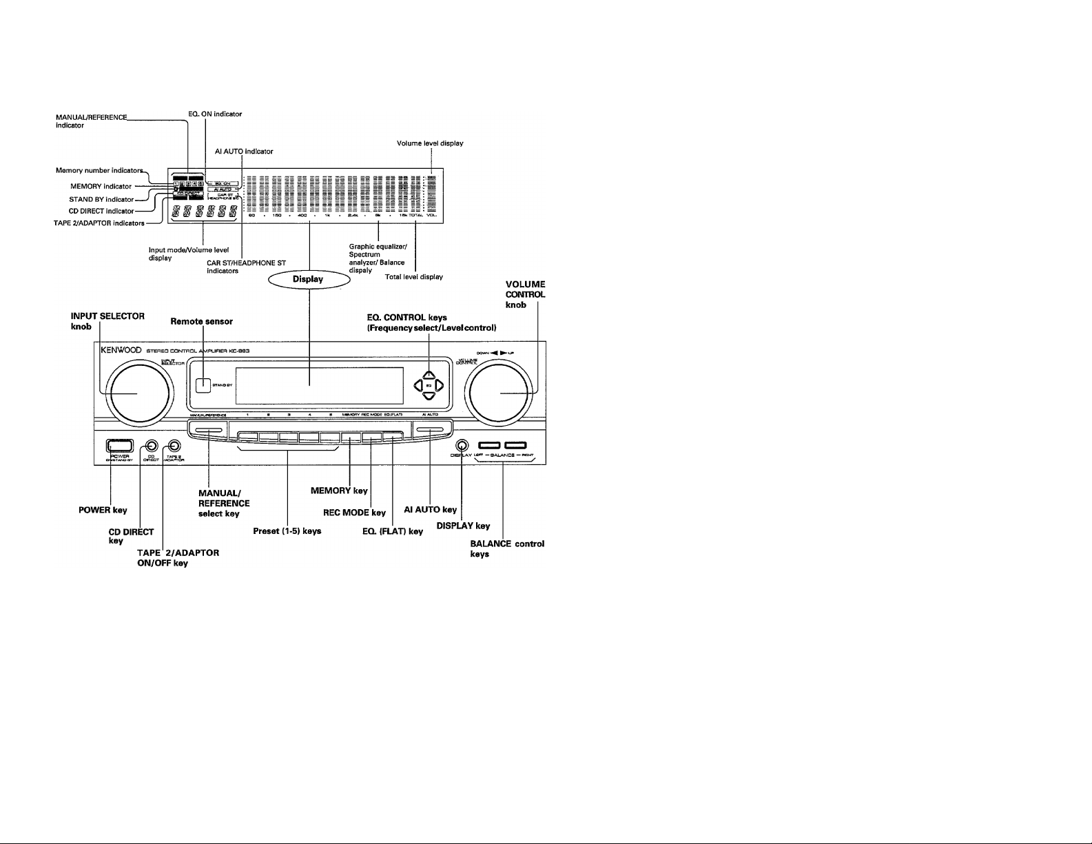
Controls and indicators
STAND BY mode of POWER key
When the power cord of this system is plugged into an AC outlet, the
STAND BY indicator lights up regardless of the ON/OFF setting of the
POWER switch. This indicates that a small amount of current is being
supplied to the unit to back up the memory contents. This mode is
referred to as the Stand By mode. While the STAND BY indicator is lit,
the power of the system can be switched ON/OFF from the remote
control unit.
Page 7
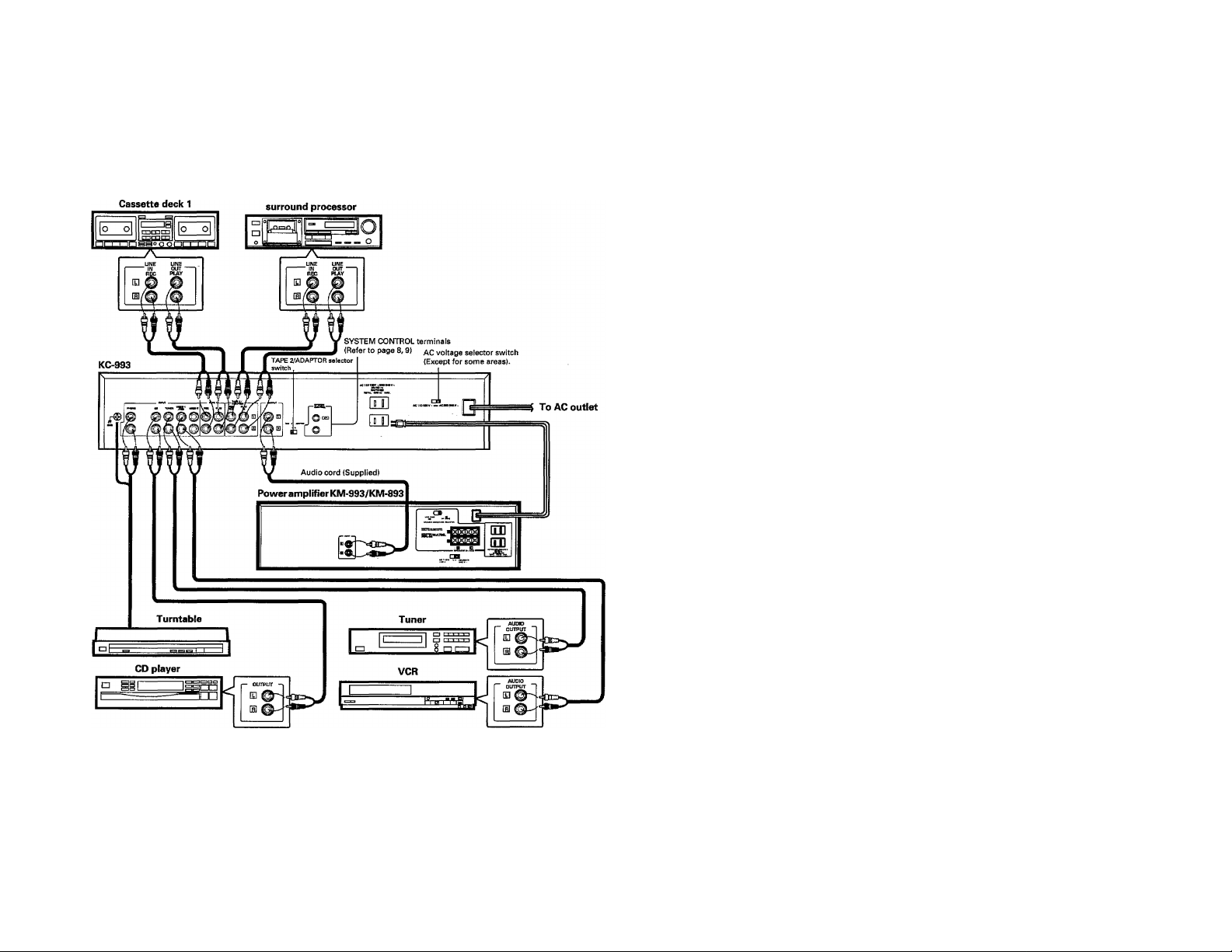
System connections
Make connections as shown below. When connecting the related system components, refer also to the instruction
manuals of the related components.
Do not plug in the power lead until ail connections are completed.
Cassette deck 2 or
Notes;
1. Connect all cords firmly. If connections are loose, there could be loss sound or noise produce.
2. When plugging and unplugging connection cords, be sure to first remove the power cord from the AC outlet. Plugging/unplugging connection
cords without removal of the power cord can cause malfunctions or damage to the unit,
3. Do not connect up a power source which is larger than that indicated on the socket at the rear of the unit.
Page 8
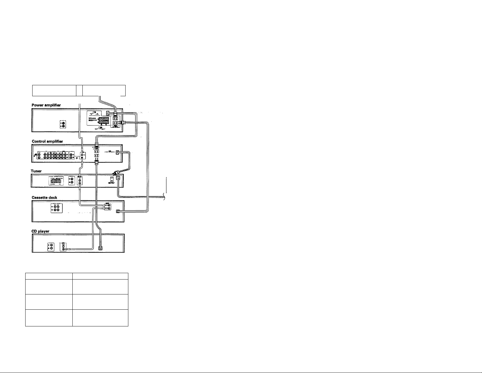
System control operation
For the system control of KENWOOD system components, connect them using the system control cords as shown in the
illustration below.
If the power cords are connected as shown in the illustration, the power of the whole system can be switched ON/OFF from
the POWER key on the control amplifier.
(For the audio cord connection, please refer to "System connections".}
Turntable
JL
Connect the power cord of the
amplifier to the UNSWITCHED AC
outlet of the tuner.
To AC outlet
AC outlet
Unit destination
U.S.A., Canada
and U.S. Military
Australia
Other countries
Note;
Do not connect the system control cord to the cassette deck connected to the TAPE 2/ADAPTOR jacks.
Shape of the AC outlet
u III
o
»
SWITCHED AC outlet
The power of the component connected to this kind of AC outlet is
switched ON/OFF in interlocked operation with the POWER key on the
main unit on which the AC outlet is installed.
8 KC-993 (En)
Page 9

SYSTEM CONTROL Operation
By connecting this unit to other KENWOOD system
components equipped with SYSTEM CONTROL terminals,
such as a tuner, tape deck, CD player and/or turntable, the
following convenient operations will be available.
Automatic play operation
When starting play with the turntable, tape deck, or CD player
connected to this unit, set the INPUT SELECTOR knob to PHONO,
TAPE or CD. The turntable, tape deck, or CD player will automatically
enter play mode.
In the same way, pressing the Play key of the turntable, tape deck, or
CD player will automatically switch the INPUT SELECTOR setting on
this unit to the component on which the Play key is pressed.
Synchro recording
To record the sound from the CD player or turntable onto a tape with
the tape deck, set the INPUT SELECTOR knob to CD or PHONO and
load a CD or record. Set the tape deck to record-pause mode, then
press the Play (START) key of the CD player or turntable. The deckwill
start recording automatically, synchronized with the CD player or
turntable starting playing. For more details, refer"to the instruction
manual of the tape deck,
Remote control
When the amplifier, tuner, tape deck, CD player, turntableand surround
processor (SS-992, SS-592) are connected via the system control
cords, these components can be controlled from the remote control
unit supplied with this unit.
1. System control operation of the cassette deck connected to the TAPE 2/ADAPTOR jacks cannot be carried out.
2. If the components connected to this unit are not KENWOOD system components, do not connect anything to the SYSTEM CONTROL terminals.
Page 10

Operating instructions
I Basic operation
INPUT SELECTOR knob
VOLUME CONTROL knob
ITo mute the sound temporarily
With the remote control unit only
Press the MUTE key.
MUTE
5
The volume level display blinks.
Pressing the key again resumes the previous volume.
Note:
When the TAPE 2/ADAPTOR selector on the rear panel is set to the
TAPE 2 position and theTAPE 2/ADAPTOR key is set to ON, the source
selected with the INPUT SELECTOR knob cannot be heard from the
speakers. To listen to a source other than cassette deck 2, be sure to
set the TAPE 2/ADAPTOR key to OFF.
10 KC-B93 [En)
Page 11

INPUT SELECTOR knob
■Operation of CD DIRECT playback
The digital sound of Compact Disc features an ideal
reproduction-characteristics, and the sound quality
provided by CD can be r^roduced with least degradation
by means of the CD direct playback function.
I Press the CD DIRECT key.
2 PIfly the CD player.
The CD DIRECT selection is given priority to any other source
being selected by the INPUT SELECTOR knob.
Notes:
1. During CD DIRECTplayback, the graphic equalizer doesjiot function.
2. When the TAPE 2/ADAPTOR selector on the rear panel is set to the
ADAPTOR position and the ADAPTOR indicator on the display is lit,
the CD DIRECT playback function cannot be carried out.
I CD DIRECTi lights up.
■ Listening to CD while recording
another source
^ Select the source to be recorded.
Set cassette deck 1 to the record-pause mode and play the source to be recorded.
3 Press the CD DIRECT key.
I CD direct! lights up.
TUNER
start recording on the cassette deck connected to the TAPE 1 jacks.
0 Play the CD player.
name of the recorded source.
The total level of the source being played and source being
recorded is displayed with spectrum analyzer.
!. theThe source name on the display remains the same, i.
KC-993 iEn) 11
Page 12

Operating instructions
When the cassette deck is connected to the TAPE 2/
ADAPTOR jacks, be sure to set the TAPE 2 /ADAPTOR
selector to the TAPE 2 position.
Set this selector only when the power is turned off.
■Ordinary tape recording
Note;
The input source cannot be changed over while the cassette deck
connected to this unit via the system cootrol cord is in the record
mode. When it is required to change the input source, put the cassette.
deck in the stop mode beforehand.
■ INPUT SELECTOR knob
■Tape dubbing (TAPE 1 -► TAPE 2)
(Recording sound with equalizer effect applied (TAPE 1 only)
To compensate the sound for general home use
^ Select a desired equalizer pattern.
Select a desired equalizer pattern from among the MANUAL
and REFERENCE preset equalizer patterns. See page 14, 15.
You can also create an equalizer pattern of your own. See
page 16.
2 Start recording.
To compensate the sound for use in a car or with stereo headphones.
Select CAR ST or HEADPHONE ST according
to your purpose, gg^i., button is pressed the
2 start recording.
12 KC-993 (En)
setting changes in the following order:
l~ CAR ST ^ HEADPHONE ST -
Page 13

Operation for components connected to the TAPE 2/ADAPTOR jacks
Before operating a component connected to the TAPE 2/
ADAPTOR jacks, be sure to set the TAPE 2 /ADAPTOR
selector on the rear panel.
For a component other
than the surround
processor SS-992 or
SS-592
M ^S-592
For the surround
processor SS-992 or
INPUT SELECTOR knob
VOLUME CONTROL knob
Set this selector only when the power is turned off.
■Using the surround processor SS-992 or SS-592
By connecting the SS-992 or SS-592 with a system control cord, the remote control unit supplied with this unit can control
it.
Press the TAPE 2/ADAPTOR key so that the
1
ADAPTOR indicator lights.
Lights up.
The volume level of the surround processor is automatically
adjusted in about 20 seconds.
The volume level of this unit is set to -35 dB.
2 Adjust the level of the surround sound.
DELAY CeUTEB ^
TIME LEVEL
(S3 (S3
Remote controi unit
For details, refer to the instruction manual supplied with the
surround processor.
3 Adjust the entire volume level.
The entire volume level can be adjusted with the
volume control of the surround processor or the
VOLUME CONTROL keys on the remote control unit.
Notes: .
1, When using a component other than the SS^2 or SS-592, be sure
to set the TAPE 2/ADAPTOR selector on the rear panel to the TAPE
2 position.
2. When the TAPE 2/ADAPTOR key is turned on, the synchronized
recording cannot be carried out.
■ Using a component other than the surround processor SS-992 or SS-592
When the TAPE 2/ADAPTOR key is set to the TAPE 2 position, the component connected to the TAPE 2/ADAPTOR jacks
will be played regardless of the setting of the INPUT SELECTOR knob. It is advisable to connect a cassette deck.
When the component connected to the TAPE 2/ADAPTOR jacks is
not being used, press the TAPE 2/ADAPTOR key so that the TAPE
2 indicator goes off.
With the TAPE 2 setting, the component connected to the TAPE 2/
ADAPTOR jacks cannot be controlled with the remote control unit
Lights up.
Note: . _
When a cassette deck is connected to the TAPE 2/ADAPTOR jacks, be sure to set the TAPE 2/ADAPTOR selector on the rear panel to the TAPE
2 position. If the TAPE 2/ADAPTOR selector is set to the ADAPTOR position, pressing the TAPE 2/ADAPTOR key increases the volume level to
the high position automatically an^ speakers may be damaged.
supplied with this unit.
KC-993 (En) 13
Page 14

Graphic equalizer operation
10 types of equalizer patterns (R1 - R5, Ml - M5) are preset in memory, allowing you to enjoy the sound according to the
genre of music.
The 5 equalizer patterns in MANUAL mode can be modified as you prefer. In addition, this unit incorporates an AI equalizer
function which automatically selects an equalizer pattern corresponding to the music being played.
■Applying a preset equalizer effect
.
...
■ "" ' " N
^ Set the equalizer to flat.
%
2 Select a desired equalizer pattern.
0 Select MANUAL mode or REFERENCE mode.
) Select the equalizer pattern with the preset key
(1-5).
The IEQ ON] indicator lights up.
When using the remote control unit, select the equalizer
pattern with the M. CALL key.
b
I Applying a sound effect with the
AI equalizer
Press the AI AUTO key.
• The unit automatically detects the proper equalizer pattern
corresponding to the music being played after sampling the sound
for about 20 seconds,
• When the sound level is low or muted, the unit cannot detect the
equalizer pattern properly,
IaFautoI
lights up.
JiltJER
Each time the key is pressed, the equalizer pattern
M.CMUJ. changes in the following order
I
-----------------
To cancel the equalizer effect
14 KC-S93 (En)
-~R5-^R4-«-R3-^ R2^-----------1
Press the EQ. (FLAT) key again.
The lEO. ONI
indicator goes off.
H\!ER
Page 15

■Table of preset equalizer patterns
R1 - R5 in the REFERENCE mode
R1 Soft:
Reproduces a soft sound appropriate for background music.
R2 Clear:
Reproduces a clear and bright sound by attenuating the level of iow
frequencies.
R3 Heavy:
Effective for playing rock music or jazz fusion music to reproduce a
dynamic sound.
R4 Scale:
Provides wide and dynamic acoustics.
R5 Movie scale:
Reproduces a “live“ atmosphere and dynamic sound when playing
the sound of movies which contain excessive high and low
frequencies.
Display function
Each time the IDISPLAYI key is pressed,
the display mode changes in the following
order:
o
M1 ~ M5 in the MANUAL mode
These preset memories [Ml - M5) are also used to store the equalizer
settings you make.
Ml Classic clear;
Effective for playing classic orchestra music with boosted mid-high
frequencies.
M2 Classic heavy:
Boosts low frequencies. When a rich bass sound is desired for
playing classic orchestra music, use this pattern.
M3 Clas^c scale;
Obtains wide acoustics when playing the classic orchestra music.
M4 Classic old;
Attenuates high frequency noise. Effective for playing sources with
noticeable noise such as classic orchestra music recorded many
years ago, reproducing agreeable sound.
MS Movie normal:
Reproduces a "live" atmosphere and dynamic sound when playing the
sound of movies.
Graphic equalizer display mode
Graphic equalizer display mode
Displays how each frequency range is compensated.
Spectrum analyzer display mode
Displays the frequency distribution of the source being played for
understanding at a glance.
Demonstration display mode
Sequentiallydisplaysvariousfunctionsofthis unit, such as equalizer
patterns^ display modes, etc.
• To exit demonstration mode, select another display mode by
pressing the jPISPLAYl key.
Al AUTO
C
HEADPHONE ST
REFERENCE
------
(R1-R5) (M1~M5)
^ MANUAL-
- CAR ST -
KC-993(En) 15
Page 16

Graphic equalizer operation
Ea CONTROL keys
■Creating an equalizer pattern
You can create a desired equalizer pattern by operating
the equalizer control keys. Observe the graphic equalizer
display and listen to the sound compensated with equ alizer
effect.
Ci ^
J Display the graphic equalizer curve.
Press the IDISPLAYI key so that the graphic equalizer display
5 in the display window. See page 15.
2 Select the frequency band to be adjusted.
Lower frequency
bands
O Adjust the level of the selected frequency
Increase the level.
Decrease the
level.
A Repeat steps 2 and 3 for other frequency
^ bands, if necessary.
Higher frequency
bands
lEQ. ONI lights up.
/£■ /7
■Storing a user-created pattern
Up to 5 equalizer patterns created by you can be stored in
memory.
f
------------------------^------------
^ Create a desired equalizer pattern.
Refer to “Creating an equalizer pattern”.
2 Press the MEMORY key.
mi c
b
The I MEMORY, 0] ,[2] 0 and [s] indicators blink for about
5 seconds on the display.
2 Press the preset key.
Press while the MEMORY indicator is lit.
The pressd preset key memorizes the equalizer pattern.
/-------- ------------- ---------- --- ---------- --- ---------- ---------- --- ---------- --- ---------- ----------
To return to the original equalizer pattern
b
16 KC-993 (En)
0 PresstheMANUAL/REFERENCEkeysothatthe IMANU.I
indicator lights.
(D Press and hold the preset key (1-5) for 5 seconds or
more.
Page 17

Remote control operation
The provided remote control unit (ROS0900) can not only be used as the system remote control unit of KENWOOD system
components, but also as a "learning” remote control which allows to program the remote control signals of other
components and operate various components from a single remote control unit.
The remote control keys can be used in two ways according to the setting of the MODE switch. The majority of the key functions in the AUDIO
mode and some of those in the VIDEO mode are the original codes preset at the factory for use in operating KENWOOD components.
AUDIO mode: Can operate KENWOOD system components.
VIDEO mode: Can program remote control signals of other video components to program them.
I Loading batteries
Battery replacement
1. If the TRANSMIT indicator will not light up when an operation key is pressed, the batteries may be exhausted. In this case, replace them with
new batteries. It is recommended to use alkaline batteries (LR03) with long iife.
2. The programmed contents are not immediately lost when the batteries are removed for replacement. However, they could be lost if the unit
is left without batteries for more than 3 minutes. In such a case, the programming should be performed again. The function signals of the non
learning, or fixed keys are not lost even in this case.
■Operating procedure
Plug the power cord of the system into an AC wall outlet,
and press the POWER key on the remote control unit to
turn the power on.
VWien the power is turned on, press the key of the source
component to be operated.
• When two operation keys on the remote control unit are pressed
successively, press each key securely reserving an interval of more
than 1 second for each press.
• Components connected via the system control cords can also be
remote-controlled, in this case, please read the instmction manual
supplied with your component.
Notes:
1. The supplied batteries are intended for use in operation checks. Therefore, their lives may be shorter than ordinary batteries.
2. When the remote-controllable distance gets shorter than before, replace both batteries with new ones.
3. Malfunction may occur tf direct sunlight or the light of a high-frequency lighting fluorescent lamp enters the remote control light sensor. In such
a case, change the system installation position to prevent the malfunction.
Approx. 6 m
Operating range
Remota sensor on
the amplifier
Remote control unit
KC-993 (En) 17
Page 18

Romote control peration
¡Names of controls (AUDIO mode)
18 KC-993 (En)
Page 19

о 5 “ о Т W
Et CD
3 “ g.
(Л м
2 CD ^
II-
i S'
s I
о cd'
“i
> á
¡s
§ 8
-S
^ Œ
O 2
m o
6
Й- Q
iff
O
a
o
(A
ё
o
5
3
o
® ä
il
Page 20

Remote control operation
■Programming operation
Remote control signals of other remote control units can be programmed under space keys on this unit. For space keys,
refer to "Modes" on the pretnous page.
Notes:
1. If the optical output level of the other remote control unit is higher,
programming may not be carried out correctly- If this occurs,
separate this unit and the other remote control unit by a greater
distance and perform the programming procedure again.
2. If the LEARN/TRANSMIT indicator blinks 4 times during
programming, this indicates either that the key being programmed
cannot be programmed or that programming has not been performed
completely. If this occurs, perform the programming procedure
again.
3. Remote control functions using signals other than infrared signals
or specially-coded signals cannot be programmed. Programming
is also impossible when this unit's memory capacity becomes full.
20 KC-993 (En)
4. The LEARN indicator goes out 30 seconds after a programmable
key is pressed. After this, programming is impossible. To continue
programming, press the programming key again.
5. When two or more programmable keys are pressed at the same
time, the key which was pressed last will be programmed.
6. Do not program the remote control functions of equipment other
than A/V components, such as air conditioners, etc.
Page 21

■ To check the programmed contents
r "" ....
^ Set to the USE position.
2 Set to the VIDEO mode.
.......
...............................
LEARN USE
AUDIO VIDEO
.........
V
mniE
3 Press the key to be checked.
* Verify that the component to be operated works correctly.
ITo change the programmed
contents
Perform the programming operation again referring to
"Programming operation" on the previous page.
• The previously-programmed content is cleared automatically and
replaced by the newly-programmed content.
■To clear the entire programmed
contents
You can clear all of the programmed contents, returning
this unit to tile initial status.
KC-S93 (En) 21
Page 22

In case of difficulty
What appears to be a malfunction may not always be serious. If your unit should not perform as e^qDected, consult the table
below to see if the problem can be corrected before seeking help from your dealer or service representative.
Amplifier, speakers
Symptom
Sound is not output.
Sound is not output from one of the
speakers.
A hum noise is generated when the
PHONO input selector key is pressed.
Remote control unit
Symptom
Remote control operation is not possible.
• The speaker cords are disconnected.
• The volume is set to the minimum position.
• The audio cords are disconnected.
• The speaker cord is disconnected.
• The BALANCE control is set to an extreme
position.
• The audio cord from the turntable is not
inserted securely into the PHONO jacks.
• The turntable is not grounded.
• Batteries are exhausted.
• The audio cords and the system control
cords are not connected properly.
• The remote control unit is too far away from
the main system, controlling angle is too
large, or there is an obstacle in between.
• The source component to be operated does
not contain the analog disc, tape(s) or CD.
• An attempt is made to play a tape which is
being recorded in the cassette deck.
• The LEARN/USE switch is set to LEARN.
Cause
Cause
Remedy
• Connect them properly referring to
"System connections".
• Adjust the volume to a proper level.
• Connect them properly.
m Connect it properly referring to "System
connections’.
• Adjust the Lefl/Right balance.
• Insert the audio cord plugs securely into
the PHONO jacks.
• Connect the grounding wire to the GND
terminal on the rear panel.
Remedy
• Replace with new batteries.
• Connect properly referring to "System
connections*.
• Operate the remote control unit within
the controllable range.
• Place an analog disc, tape(s) or CD in the
source component to be played.
• Wait until the recording is completed.
• Set the LEARN /USE swlteh to USE.
Notes;
1. This system is microprocessor-controlled, so malfunction may occurdue to external noise or interference noise. In such a case, unplug the power
cord, plug it and turn power on again.
2. Do not use contact cleaners because it could cause a malfunction, Be specially careful against contact cleaners containing oil. for they may
deform the plastic components.
22 KC-993 (En)
Page 23

Specifications
Caution: Read this page carefully to ensure safe operation.
A
Frequency re^once.....................................................................
Input sensitivity/impedance
PHONO
....................................................................................
TUNER/TAPE/VIDEO
CD..
................................................................................................ 450mV/47k£i
TAPE 2/ADAPTOR
Signal-to noise ratio (IHF-A)
PHONO..................................................................................... 78 dB for 3.0 mV input
TUNER/TAPE/CD/VIDEO........................................................ 102 dB
Phono maximum input level
Total harmonic distortion
20Hz to 20,000 Hz .................................................................
Graphic equalizer control
(60 Hz, 150 Hz, 400 Hz, 1 kHz, 2.4 kHz,
6 kHz, 15 kHzl
Output voltage and impedance
Tape REC.................................................................................
PREOUT
..................................................................................
General
Power consumption
AC outlets
SWITCHED
Dimensions
Weight (Net).................................................................................
Note:
KENWOOD follows a policy of continuous advancements in development. For this reason specifications may be changed without notice.
.......................
.........
....................................................
..................................................................
......................................................
.........................................................................
.........................................................
...................................
........................................... For USA and Canada: 2; (Total 780 W, 6.5 A max.)
........................................................... W; 440 mm (17-5/6")
10 Hz to 50 kHz, 0 dB, ~Z dB
3.0 mV/47 kO
280 mV/47 kil
280 mV/47 kO
100 mV, T.H.D. 0.5% at 1 kHz
0.005% at rated output
+10 dB
280 mV/3.3 kQ
IV/I.Okft
20 W
For other countries: 2; (Total 480 W)
H: 99 mm (3-7/8")
D: 284 mm (11-3/16")
3.3 kg (7.3 lb)
For CANADA
DOC REGULATION
"This digital apparatus does not exceed the CLASS B limits for radio noise emissions from digital apparatus as set out in the radio interference
regulations of the Canadian Department of Communications."
For the U. S. A.
FCC WARNING:
This equipment may generate or use radio frequency energy. Changes or modifications to this equipment may cause harmful interference unless
the modifications are expressly approved in the instruction manual. The user could lose the authority to operate this equipment if an unauthorized
change or modification Is made.
NOTE;
This equipment has been tested and found to comply with the limits for a Class B digital device, pursuant to Part 15 of the FCC Rules. These limits
are designed to provide reasonable protection against harmful interference in a residential installation. This equipment may cause harmful
interference to radio communications, if it is not installed and used in accordance with the instructions. However, there is no guarantee that
interference will not occur in a particular installation. If this equipment does cause harmful interference to radio or television reception, which can
be determined by tuning the equipment off and on, the user is encouraged to try to correct the interference by one or more of the following measures;
— Reorient or relocate the receiving antenna.
— Increase the separation between the equipment and receiver.
— Connect the equipment into an outlet on a circuit different from that to which the receiver is connected.
— Consult the dealer or an experienced radio/TV technician for help.
KC-393 (En) 23
Page 24

KENWOOD
 Loading...