

Kenwood GX-SEF2, GX-LEF2, GX-REF2 Service Manual
6CD/CASSETTE & HEATER CONTROL RECEIVER
GX -201 KEF2/LEF2
Q
Q
7
3
6
/REF2/SEF2
3
1
5
1
5
0
SERVICE MANUAL (TENTATIVE
SUBARU GENUINE
TEL 13942296513 QQ 376315150 892498299
GX-201LEF2
COMPACT
DIGITALAUDIO
VOL ADJ
DOLBY B NR
TUNE
TRACK
REG
B NR
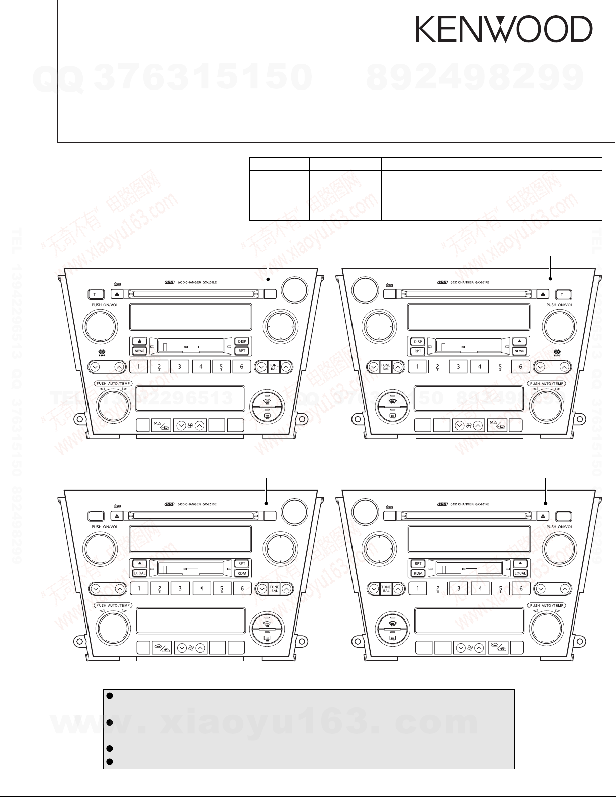
Model Model Name Parts No. Destination
GX-201LE GX-201LEF2 86201AG410 Europe (left-hand-drive cars)
GX-201RE GX-201REF2 86201AG310 Europe (right-hand-drive cars)
GX-201KE GX-201KEF2 86201AG210 Other Areas (right-hand-drive cars)
GX-201SE GX-201SEF2 86201AG510 Other Areas (left-hand-drive cars)
Panel assy
( - )*
LOAD
CD
CHR BAND
TAPE
LOCAL
DX
SCAN
RDM
GX-201REF2
8
CD
CHR BAND
TAPE
9
)
COMPACT
DIGITALAUDIO
LOAD
LOCAL
4
2
© 2003-8 CREATED IN JAPAN
B53-0087-00 (N) 0
SCAN
RDM
DX
B NR
ANTI-THEFT SYSETM
9
DOLBY B NR
8
2
9
Panel assy
( - )*
REG
TUNE
TRACK
9
TEL 13942296513 QQ 376315150 892498299
VOL ADJ
TEL
GX-201SEF2
SCAN
w
w
13942296513
MODE
A/COFF
Panel assy
( - )*
COMPACT
DIGITALAUDIO
DOLBY B NR
TUNE
TRACK
w
B NR
MODE
A/COFF
* Part number of panel assy is undecided.
The knobs with numbers larger than 700 on exploded view are not supplied for service parts because
it is difficult to apply grease. Please change to panel assy (PA1) when you need repair to the knob.
The 6CD mechanism has not supplied repair parts for each part (for Optical Laser pickup, motor etc).
.
If you need repair to the 6CD mechanism please change to mechanism assy (D40-1170-15).
DC cord for service : E30-3801-15
Antenna connector replacement cord for service : E30-6255-05
xia
o
y
LOAD
CHR BAND
u
CD
TAPE
Q
Q
1
6
6
7
3
GX-201KEF2
3
1
3
CD
CHR BAND
TAPE
.
DIGITALAUDIO
LOAD
COMPACT
5
c
1
5
MODE
B NR
MODE
o
0
9
8
A/C OFF
DOLBY B NR
A/C OFF
m
2
4
9
9
9
2
8
Panel assy
( - )*
TUNE
TRACK
SCAN
GX-201KEF2/LEF2/REF2/SEF2
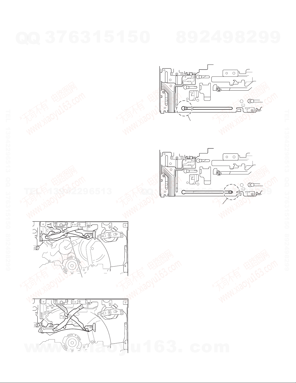
CAUTION ON TRANSPORTING
7
Q
Q
When transporting the unit, 6CD-CH mechanism must be
put into the transport mode.
■ How to Achieve the Transport Mode
In order to achieve the transport mode, there should be no
disk and the mechanism nor should the mechanism be in the
waiting mode for disk loading.*
After displaying [NO DISC], turned off the ACC power source.
Keep the BU power source on.
TEL 13942296513 QQ 376315150 892498299
* Non-waiting mode for disk loading
•Non-waiting mode for disk loading means the state where
the mechanism is displaying [NO DISC] and where the
mechanism shutter is closed.
•In other words, [NO DISC] is displayed 15 seconds after
the disk is taken out or when the shutter of the mechanism
is closed and [LOAD] key is pressed. (Pressing the [LOAD]
key causes the mechanism to enter the waiting and nonwaiting mode alternatively.)
• Pressing other source keys after taking all the disks out,
the mechanism shutter closes and it goes into non waiting
mode for disk loading. (At this point the display will indicate
the source selected and does not display [NO DISC].)
TEL
3
13942296513
6
3
1
5
1
5
0
2. Center Scre w condition (By the e xternal view of the mechanism, it is possible to make judgment on this by the PLATERACK pin position.)
7
3
Q
Q
2
9
8
PLATE-RACK PIN
Fig. 3 Transport mode
0
5
1
5
1
3
6
4
9
8
9
8
2
4
2
9
8
9
2
9
9
TEL 13942296513 QQ 376315150 892498299
9
■ Transport Mode Condition
1. Rear Arm condition (This can be confirmed in the condition
where the mechanism cover is in place.)
REAR ARM
Fig. 1 Transport mode
PLATE-RACK PIN
Fig. 4 Up/Down center screw connection condition
■
The Reason to Put the Mechanism in the T ransport Mode
1. Protection of Rear Arm
Putting the mechanism into the transport mode is a protection against the Rear Arm to get deformed from the vibration during transport or sudden fall. Deformity in the Rear
Arm may result in loss of strength for holding the disk in
place.
2. Protection against error at the time of initial search
Putting the mechanism into the transport mode is also a
protection against an error or mechanism lock when the
power is put on again. When the back up is turned off , platerack pin could move from the vibration during transport or
sudden fall.
This would cause the system to go into an error detection
of the center screw is not in connection although, in fact, it
is in connected condition.
2
w
w
w
Fig. 2 Waiting mode for disk loading
.
xia
o
y
u
1
6
3
.
c
o
m
GX-201KEF2/LEF2/REF2/SEF2
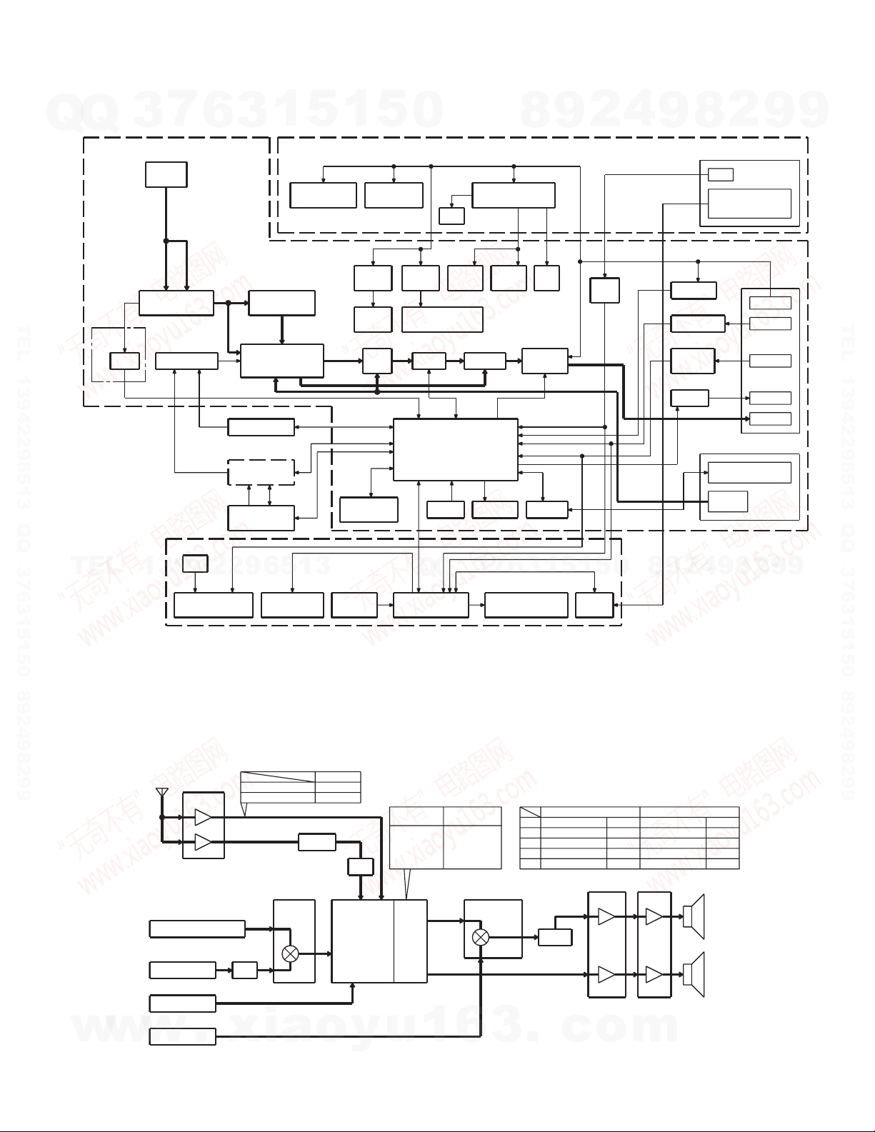
BLOCK DIAGRAM
7
Q
Q
(X14- ) (X89-254)
TEL 13942296513 QQ 376315150 892498299
3
W1
FM/AM
ANT
A3 IC12
(2-71,
2-72)
ONLY
IC13,
FA/AM TUNER
(FRONT END)
IC2114
RDS MUTE
AM
FM
SELECTOR
(X25-929)
6
(X87-3052-70)
1
3
AM NOISE
CANCELLER
IC22
E-VOL/
SIGNAL
PROCESSOR IC
6CD MECHA
DOLBY (IC1)
CASSETTE
MECHA
5
1
5
6CD SERVO
AVR AVR
CASSETTE BU5V, AUDIO8V,
DC/DC
AVR
A1 A2
DC/DC
AUDIO HEAT CONTROL
IC23
FRONT
NAVI
SW
REAR
X81
OSC
12.582MHz
0
IC11IC21IC31
LED10V AVR
X25
DC/DC
AVR
DC/DC
IC81
AVR AVR
IC31-34Q401,402
FIX-EQ
SYSTEM u-COM
IC82
RESET BUS I/F
BUZZER
FM 8VAM 8V
BZ81
8
SW
5V
IC41
POWER
AMP
9
Q813Q102Q104Q605Q602
IC83
2
Q808
IGN
DET
4
9
Q815
BU DET
Q807
ACC DET
Q802,823,824
ILLM +/DET
Q816
P-ANT
2
8
J1
IGN
AIR-CONDITIONER
UART
COMMUNICATION
J1
BUS
(COMMUNICATION)
BUS
(AUDIO)
J2
9
BU
ACC
ILLM +/-
P-ANT
SP
9
TEL 13942296513 QQ 376315150 892498299
TEL
w
w
13942296513
w
X89
LED
ILLUMINATION FL DISPLAY
ANT
TUNER
CASSETTE-MECHA
CS : DOLBY LEVEL300mV-rms
6CD-MECHA
CD : 1.2V-rms
EXT-UNIT
CH : 1.2V-rms
NAVI
.
NAVI : 1.2V-rms
GX-201KEF2
GX-201REF2/LEF2
FM
AM : 215mV-rms
AM
IC24
ISO
-1dB
xia
AUDIO KEY
500mV-rms
270mV-rms
IC12
AM/NC
0dB
SELECTOR
0dB
0dB
o
5
1
3
6
7
3
Q
Q
MATRIX I/F
PANEL
u-COM
FL DISPLAY
LEVEL DIAGRAM
FM
LEVEL DIFFERENCE OF EACH SAUCE
-1.5dB
-23.8dB
3
(CH 1W OUTPUT)
6CD
GX-201KEF2 GX-201REF2/LEF2
1kHz 30% mod.
AM
1kHz 75kHz dev.
FM
315kHz 0dB
CS
1kHz 0dB
1kHz 0dB
CH
Q401,
402
MUTE
-0.5dB
.
c
-7.5dB
LPF
MPX,
LOUD,
E-VOL,
BASS,
TRE,
MID
y
GX-201KEF2
CD : +6dB
CS : +8dB
: +5dBCH
FM : +7dB
: +16dBAM
FAD,
BAL
u
FRONT
REAR
1
GX-201REF2
GX-201LEF2
: +6dB
CD
: +8dB
CS
: +5dB
CH
: +10.5dB
FM
: +18dB
AM
IC23IC22IC21
SELECTOR
6
1
UARTHEAT CONTROL
5
Q24,
25ED2 or ED3IC1ED1
-16.5dB
IC31-34
FIX-EQ
+7.7dB
-2.5dB
o
0
-18dB
-6dB
-1dB
0dB
m
9
8
1kHz 30% mod.
1kHz 40kHz dev.
315kHz 0dB
1kHz 0dB
1kHz 0dB
IC41
AMP
+26dB
+26dB
2
4
-16.5dB
FRONT
SP
REAR
SP
9
-16dB
-8dB
-1dB
0dB
8
2
9
9
3

GX-201KEF2/LEF2/REF2/SEF2
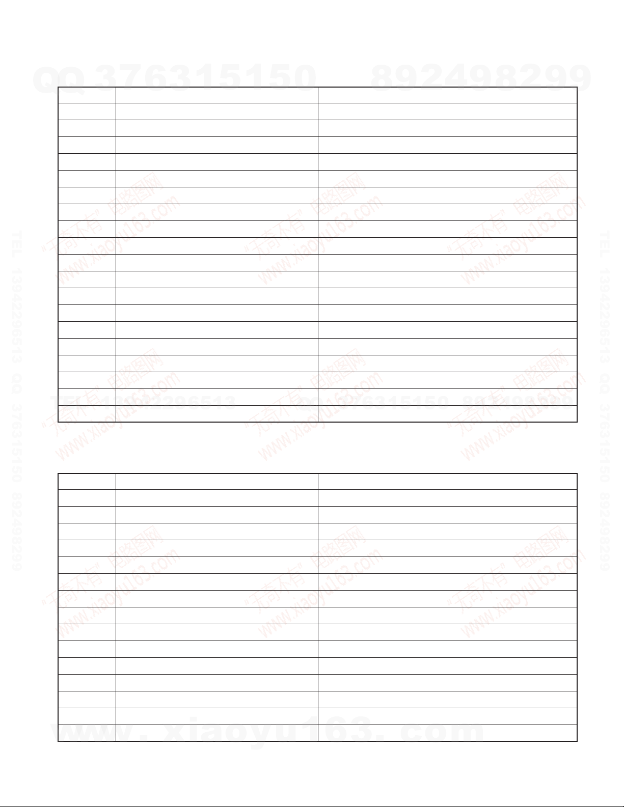
COMPONENTS DESCRIPTION
7
Q
Q
● SYNTHESIZER UNIT (X14-694x-xx)
Ref. No. Application / Function Operation / Condition / Compatibility
IC1 Cassette mechanism sub-motor IC Cassette sub-motor power supply
IC11 FM diversity IC FM diversity switching (Only for GX-201KEF2)
IC12 AM noise canceller IC AM noise canceller
IC13 2-piece ope-amp RDS noise amp (Only for GX-201LEF2/REF2)
IC14 RDS demodulation IC RDS demodulation (Only for GX-201LEF2/REF2)
IC21 Ope-amp with switch CD/Cassette switching
TEL 13942296513 QQ 376315150 892498299
IC22 Electronic volume BASS/MID/TRE, MPX, Mute, Electronic volume
IC23 Ope-amp with switch Audio/NAVI switching
IC24 2-piece ope-amp CD isolation amp, LPF
IC31~34 4-piece ope-amp FIX-EQ
IC35 2-piece ope-amp 1/2 VCC output
IC41 Power amp 4ch power amp
IC81 System µ-com System control
IC82 Reset IC System reset detection
IC83 I2C BUS IC F-BUS communication
IC84 2-piece NOR circuit For hard muting
IC85 EEPROM Bug counter-measure
TEL
IC86,87 Inverter circuit F-BUS control
Q1,2
Q101 Diversity switch When turned ON, turns diversity OFF (Only for GX-201KEF2)
Q102,103 FM power supply switch When FM, 8V output
Q104,105 AM power supply switch When AM, 8V output
Q106 IF count detection When detecting IF count, Lo output
Q107 RDS data buffer RDS data buffer output (Only for GX-201LEF2/REF2)
Q108 S-meter buffer S-meter voltage output
Q151,152 Noise amp Noise detection constant switching (Only for GX-201LEF2/REF2)
Q153 Noise amp Noise detection output buffer (Only for GX-201LEF2/REF2)
Q202 Mute switch For muting within electronic volume
Q401,402 NAVI mute For NAVI muting at interruption
Q403 SVR switch For SVR discharging
Q404 SVR switch For SVR discharging at over voltage
Q601,602 Audio DC/DC power supply switch For DC/DC audio
Q604,605 Heater DC/DC power supply switch For DC/DC heater
Q606,607 DC/DC control switch For switching internal frequency
Q650 Audio DC/DC power supply switch For DC/DC audio
Q651 Heater DC/DC power supply switch For DC/DC heater
Q801 Buzzer switch For buzzer
w
3
13942296513
Cassette mechanism main motor power supply switch
w
w
6
.
xia
3
1
5
o
1
y
5
u
0
7
3
Q
Q
For cassette mechanism main motor
1
6
3
6
8
3
.
9
1
1
5
c
2
5
o
4
0
m
9
8
9
8
2
4
2
9
8
9
2
9
9
TEL 13942296513 QQ 376315150 892498299
9
4
GX-201KEF2/LEF2/REF2/SEF2
COMPONENTS DESCRIPTION
7
Q
Q
TEL 13942296513 QQ 376315150 892498299
TEL
3
Ref. No. Application / Function Operation / Condition / Compatibility
Q802 Illumination + detection For illumination + detection
Q803 Reset output switch for F-BUS When resetting F-BUS, Hi output
Q804 NAVI mute switch When muting NAVI, Hi output
Q805 IF count detection When detecting IF count, Lo output
Q806 P-ANT circuit control switch When tuner, GND electric potential output
Q807 ACC detection When ACC ON detection, Lo output
Q808 IGN detection When IGN ON detection, Lo output
Q809 SYS_ON current buffer When SYS_ON Hi, Lo output
Q810 Hard reset switch When HARD_RESET ON, Lo output
Q812 BUS_OFF switch When F-BUS system OFF, Hi output
Q813 P-ON5V power supply switch For P-ON5V
Q815 BU detection When BU ON, Lo output
Q816 P-ANT circuit control switch When tuner, BU electric potential output
Q817,818 P-ANT circuit protection P-ANT short circuit protection
Q820 F-BUS mute output When mute ON, Hi output
Q821 BUS_ON detection When F-BUS system ON, Hi input
Q822 BUS_ON switch When F-BUS system ON, Hi output
Q850,852 Illumination - detection switch When detecting illumination -, Hi output
Q853 Illumination - detection switch When detecting illumination -, Lo output
13942296513
6
3
1
5
1
5
0
Q
Q
3
7
6
8
3
9
1
5
1
2
5
4
0
9
8
9
8
2
4
2
9
8
9
2
9
9
TEL 13942296513 QQ 376315150 892498299
9
● SWITCH UNIT (X25-929x-xx)
Ref. No. Application / Function Operation / Condition / Compatibility
IC1 Display control µ-com VFD control, Key intake
IC3 EEPROM For bug counter-measures
Q1 Audio VFD5V switch When audio VFD ON, 5V output
Q2 Audio VFD5V switch When audio DC/DC ON, Lo output
Q4 Heater VFD5V switch When heater VFD ON, 5V output
Q5 Heater VFD5V switch When heater DC/DC ON, Lo output
Q11 F differential indicator power supply switch When F-differential indicator ON, 5V output
Q12 R differential indicator power supply switch When R-differential indicator ON, 5V output
Q21 Multiple-push reset circuit detection When detecting REP/RDM, DWN_SEEK, Hi output
Q22 Multiple-push reset circuit detection When resetting by multiple push, Lo output
Q23 Multiple-push reset circuit detection When TONE (BAL/FAD) detected, Lo output
Q24 Heater UART communication control Heater UART communication control (TX)
Q25 Heater UART communication control Heater UART communication control (RX)
Q26 SW5V power supply switch When IGN ON, 5V output
Q27 Panel illumination switch When panel illumination ON, 10V output
w
w
w
.
xia
o
y
u
1
6
3
.
c
o
m
5
GX-201KEF2/LEF2/REF2/SEF2
COMPONENTS DESCRIPTION
7
Q
Q
Ref. No. Application / Function Operation / Condition / Compatibility
Q28 Panel illumination switch When panel illumination ON, GND electrical potential
Q29 F differential indicator dimmer control When dimmer OFF, GND electrical potential
Q30 R differential indicator dimmer control When dimmer OFF, GND electrical potential
Q33 System reset detection When system is reset, Hi output
Q34 Dimmer current counter-measure When audio encoder ON, 5V output
Q35 System reset detection When system is reset, Lo output
Q36,37 6CD breakup counter-measure FL (H) discharge circuit
TEL 13942296513 QQ 376315150 892498299
● DOLBY NOISE REDUCTION UNIT (X87-3052-70)
Ref. No. Application / Function Operation / Condition / Compatibility
IC1 Dolby NR Dolby BNR, Cassette EQ, Music sensor
Q1 Music sensor level switching Gain switching of dolby IC
● DAUGHTER UNIT (X89-2542-71)
Ref. No. Application / Function Operation / Condition / Compatibility
IC11 Various constant voltage power supply output 5V, 8V, 10V constant voltage power supply
TEL
IC21 CAS servo 8V power supply For CAS servo
IC31 CD servo 8V power supply For CD servo
Q101 Panel illumination power supply switch When illumination + input, 5V output
Q201~203 CAS servo power supply switch For CAS servo
Q301~303 CD servo power supply switch For CD servo
3
13942296513
6
3
1
5
1
5
0
Q
Q
3
7
6
8
3
9
1
5
1
2
5
4
0
9
8
9
8
2
4
2
9
8
9
2
9
9
TEL 13942296513 QQ 376315150 892498299
9
6
w
w
w
.
xia
o
y
u
1
6
3
.
c
o
m
GX-201KEF2/LEF2/REF2/SEF2
MICROCOMPUTER’S TERMINAL DESCRIPTION
7
Q
Q
● SYSTEM MICROCONTROLLER IC : 703037AGF-A15 (X14 : IC81)
Pin No. Pin Name I/O Application Processing Operation Description
TEL 13942296513 QQ 376315150 892498299
TEL
w
3
1 SC_DATAIN O Slave data output (Panel communication) (UART) 19200bps
2PLL_SDA I/O F/E (+EEPROM) data input/output (I2C) 100kHz or less
3 R_DATA (NC) I (O) RDS data input (M, General type : Open, not used)
4 PLL_SCL O F/E (+EEPROM) clock output (I2C) 100kHz or less
5 R_QUAL (NC) I (O) RDS quality (M, General type : Open, not used)
6 CDX_SI I 6CD data input (SIO) 250kHz
7 CDX_SO O 6CD data output (SIO) 250kHz
8 CDX_CLK I 6CD clock input (SIO) 250kHz
9 EVDD - 5V electrical potential
10 EVSS - GND electrical potential
11 BEEP O BEEP output Buzzer : H (pulse) 2kHz
12 IFC I F/E IFC OUT input Station found : L, Other : H
13 AM+B O AM power supply output AM : H, Other : L
14 FM+B O FM power supply output
15 ILL_DET- I
16 ILL_DET+ I ILL+ detection (Vehicle small signal) ILL+ ON : L
13942296513
17 NC O Not used Open
18 MUSIC I CS between music detection Between music : H, Music detection : L
19 DOLBY O CS dolby switching NR ON : H, NR OFF : L
20 EQ_MUTE O CS EQ mute PLAY : L, FF/REW DPSS : H
21 IC/VPP - Write voltage
22 CDX_MTS O 6CD communication request output
23 MTL I CS metal SW Normal : H, Metal, CrO2 : L
24 F/R O CS F/R switching FWD : L, REV : H, Initial : L
25 MSC O CS gain switching at music select G1 (-40dBm) : L, G2 (-60dBm) : H
26 BUS_DI I IE-BUS data input
27 BUS_DO O IE-BUS data output
28 IC2_SDA I/O IC2 data input/output (I2C) 100kHz or less
29 IC2_SCL O IC2 clock output (I2C) 100kHz or less
30 NC O Not used Open
31 A_SEL O Audio selection CD : H, CS : L
32 MUTE O Audio mute Mute : H, Normal : L
33 AFS (NC) O
34 RESET I System reset input Reset : L, Reset voltage : 4.2V, Reset at rise of L→H
35 XT1 I Sub-system clock oscillation terminal
w
w
6
.
xia
1
5
1
3
ILL- detection (
Switching constant at noise detection
o
5
Vehicle
illumination control signal)
y
u
0
Q
Q
1
3
6
7
3
4
2
9
8
RDS operation : H (FM : H),
Other than RDS operation : L (Other : L)
ILL- ON (GND) : H (Pulse input)
0
5
1
5
1
3
6
FM, AM seek : L (J, M, General type : Open, not used),
RDS operation : H, Other than RDS operation : L
.
c
o
9
9
8
m
2
8
4
2
9
8
9
2
9
9
TEL 13942296513 QQ 376315150 892498299
9
7
GX-201KEF2/LEF2/REF2/SEF2
MICROCOMPUTER’S TERMINAL DESCRIPTION
7
Q
Q
Pin No. Pin Name I/O Application Processing Operation Description
36 XT2 - Sub-system clock oscillation terminal
37 REGC 38 X2 - Main system clock oscillation terminal 12.58MHz
39 X1 I Main system clock oscillation terminal 12.58MHz
40 VSS - GND electrical potential
41 VDD - 5V electrical potential
42 NC O Not used Open
TEL 13942296513 QQ 376315150 892498299
43 HARD_RESET O Hard reset output Reset : H
44 NAVI_SW O NAVI voice switching NAVI interruption : H, Normal : L
45 NAVI_MUTE O
46 DC/DC_FREQ O DC/DC oscillation frequency control AM 5kHz step 750~900, 1110~1270, 1480~1630 : Hi,
47 NC (DIVER) O Not used (Diversity antenna control) M type : Test mode : H (OFF) or L (ON) switching
48 P_STBY O Power IC standby control ACC ON, POWER ON : H, Other : L
TEL
49 P_MUTE O Power IC mute control This mute should not be normally used when playing
50 SVR O SVR control Normal : L, Discharge : H
51 ANT_CON O Power antenna control
52 NC O Not used Open
53 IGN_DET I IGN detection IGN ON : L, IGN OFF : H, Detection voltage : 8V
54 ON_REQ I F-BUS ON request System ON request : L
55 SYS_ON O F-BUS ON output System ON : H
56 CDX_STM I 6CD communication request input Communication request : L
57 SYS_OFF O F-BUS OFF output System OFF : H
58 BVDD - 5V electrical potential
59 BVSS - GND electrical potential
60 BUS_STBY O BUS IC standby control System ON : H
61 PON O Power ON control
62 DC/DC_H O DC/DC (For of HTR-VFD) control
63 DC/DC_A O DC/DC (For AUDIO-VFD) control
64 MOTOR O CS main motor control Main motor ON : H
w
3
13942296513
w
w
6
.
xia
1
5
1
y
5
u
0
Q
Q
1
3
6
3
NAVI voice Frontch interruption mute (When switching)
o
7
3
4
2
9
8
NAVI interruption start/release : L, Normal : H
AM 9kHz step 747~900, 1125~1287, 1494~1629 : Hi,
Other : L
E, General type : Open, not used
(Initial : H), Normal mode : L (DIVER ON)
Mute : L, Other : H
5
1
3
6
is broken off such as search during play.
Tuner ON : H, RDS operation during other sources : H,
Other : L
Power ON : L, Power OFF : H, Stabilization time 400ms
HTR ON : H, HTR OFF : L, Stabilization time 550ms,
Turn to H after receiving panel µ-com HVFD_ON : H
AUDIO ON : H, AUDIO OFF : L, Stabilization time 500ms,
Turn to H after receiving panel µ-com AVFD_ON : H
.
c
1
0
5
o
9
9
8
m
2
8
4
2
9
8
2
9
9
9
TEL 13942296513 QQ 376315150 892498299
9
8
GX-201KEF2/LEF2/REF2/SEF2
MICROCOMPUTER’S TERMINAL DESCRIPTION
7
Q
Q
Pin No. Pin Name I/O Application Processing Operation Description
TEL 13942296513 QQ 376315150 892498299
TEL
w
3
65 SUB+ O CS sub-motor control
66 SUB- O CS sub-motor control
67 MODE3 I CS FF/REW/FWD/REV detection
68 MODE1 I CS FF/REW/FWD/REV detection
69 MODE2 I CS FF/REW/FWD/REV detection
70 CDX_ACC O 6CD ACC Operating 6CD : L, Other : H
71 CDX_RST O 6CD reset Reset : L, Normal : H
72 CDX_EJEREQ O Eject request Eject : L
73 REF_CON O A/D port reference voltage output ACC ON : H, Other : L
74 AVDD - 5V electrical potential
75 AVSS - GND electrical potential
76 AVREF I A/D port reference voltage input
77 CDX_DDCNT I 6CD servo control 6CD ON : H
78 CDX_MUTE I 6CD mute request Mute : L
79 RREEL I CS reel pulse (AD input) CS reverse rotation side reel photo input
80 FREEL I CS reel pulse (AD input) CS foreword rotation side reel photo input
81 DIAG I Test mode terminal Test mode : L, Normal : H
82 TYPE1 I Destination setting 1
13942296513
83 TYPE2 I Destination setting 2
84 TYPE3 I Destination setting 3
85 NOISE I FM noise detection (AD input)
86 SMETER I S-meter (AD input)
87 NC I Not used
88 SCRTY I Forced security release Release : L, Other : H
89 SC_CON O Slave ON/OFF control (Panel communication) ON : H, OFF : L
90 MC_REQ I Master ON request (Panel communication) ON request : H
91 ACC_DET I ACC detection ACC ON : L, ACC OFF : H, Detection voltage : 8.5V
92 OFF_REQ I F-BUS OFF request System OFF request : L
93 BU_DET I BU detection
94 SC_RST O Slave reset (Panel communication)
95 SC_BKUP O
96 R_CLK (NC) I (O) RDS clock M, General type : Open, not used
97 FLASH_SI O Not used Open (For flash writing)
98 FLASH_SO O Not used Open (For flash writing)
99 FLASH_CLK O Not used Open (For flash writing)
100 MC_DATAIN I Slave data input (Panel communication) (UART) 19200bps
w
w
6
.
xia
1
5
1
y
5
u
0
Q
Q
1
6
3
Reduced electricity detection (Panel communication)
o
3
7
3
4
2
9
8
0
5
1
5
1
3
6
NOISE value : With 2.9V or less, station found permission
SMETER value : According to the data written in EEPROM
BU ON : L, BU OFF (At instant reduction) : H,
Detection voltage : 8.5V
Normal : H, Reset : L (2 pulses),
Immediately after reset, communication error : Reset
Electricity reduced product : L, Normal : H
.
c
o
9
9
8
m
2
8
4
2
9
8
9
2
9
9
TEL 13942296513 QQ 376315150 892498299
9
9
GX-201KEF2/LEF2/REF2/SEF2
MICROCOMPUTER’S TERMINAL DESCRIPTION
7
Q
Q
● PANEL MICROCONTROLLER : 90587CAPFV13x (X25 : IC1)
Pin No. Pin Name I/O Application Processing Operation Description
1 KR2_A I Key matrix (RET : 2Bit)
2 KR3_A I Key matrix (RET : 3Bit)
3 KR4_A I Key matrix (RET : 4Bit)
4 KR5_H I Key matrix (RET : 5Bit)
5 KR6_H I Key matrix (RET : 6Bit)
6,7 NC O Not used, Open
TEL 13942296513 QQ 376315150 892498299
8AVFD_ON O Audio VFD power supply ON signal When stopped (L) : Power supply OFF,
9 VSS - Within-chip ground GND
10~15 NC O Not used, Open
16 HMC_DATA I Heater ECU communication (Reception) Conducts communication (Reception) with A/C
17 HSC_DATA O Heater ECU communication (Transmission) Conducts communication with A/C (transmission)
18,19 NC O Not used, Open
20 AVFD_DATA O
21 VCC - Power supply input terminal BU5V connection
22 AVFD_CLK O VFD tube communication for audio (Clock)
TEL
23 SCL O Serial clock for E2PROM Output to E2PROM as I2C clock signal
24 SDA I/O Serial data for E2PRROM Input/Output to E2PROM as I2C data signal
25 C - Terminal for voltage stabilization 0.1µF capacitor connection
26 TYPE1 I Left/Right steering wheel judgment H : Left steering wheel, L : Right steering wheel
27 TYPE2 I Judgment on security condition H : Security, L : No security
28 DVRH - Connected to GND as D/A converter not used GND
29 DVSS - Ground the terminal for D/A converter GND
30,31 NC O Not used, Open
32 AVCC - Power supply input terminal A/D converter VCC
33 AVRH - Connected to GND as A/D converter not used GND
34 AVRL - Connected to GND as A/D converter not used GND
35 AVSS - Ground the terminal for A/D converter GND
36 NC O Not used, Open
37 HVFD_DATA O
38 HVFD_CLK O Heater VFD tube communication (Clock)
39 NC O Not used, Open
40 VSS - GND connection terminal GND
41 ACC_DET I Detection of ACC Hi : No ACC, Lo : With ACC
w
42 SW5V_ON O UART buffer power supply control
3
13942296513
w
w
6
VFD tube communication for audio (Transmission)
Heater VFD tube communication (Transmission)
.
xia
3
1
5
o
1
y
5
u
0
Q
Q
1
Controls power supply for Audio FL tube.
Normal operation (H) : Power supply ON
Display data transmission for audio FL tube
Audio VFD synchronization clock output during serial communication
7
3
Display data transmission to A/C FL tube
Heater VFD tube communication synchronization clock
output for serial communication
When IGN ON L : ON (SW5V) output,
6
3
When IGN OFF H : OFF (SW5V) output
6
8
3
.
9
1
1
5
c
2
5
o
4
0
m
9
8
9
8
2
4
2
9
8
9
2
9
9
TEL 13942296513 QQ 376315150 892498299
9
10
GX-201KEF2/LEF2/REF2/SEF2
MICROCOMPUTER’S TERMINAL DESCRIPTION
7
Q
Q
Pin No. Pin Name I/O Application Processing Operation Description
TEL 13942296513 QQ 376315150 892498299
TEL
w
3
43,44 NC O Not used, Open
45 IGN_DET I External interruption 0 (IGN signal)
46 SC_BKUP I
47 MD0 I Used when writing to flash ROM Hi : Normal mode, Lo : FLASH writing mode
48 MD1 I Used when writing to flash ROM Hi : Normal and FLASH writing mode, Lo : No setting
49 MD2 I Used when writing to flash ROM Hi : FLASH writing mode, Lo : Normal mode
50 HST I L : Hardware standby condition VCC
51,52 NC O Not used, Open
53 SC_CON I External interruption 4 (Audio SC-CON signal) start/stop is made as external interruption from audio.
54 KR0_A I External interruption 5 (Interruption key RET0)
55 KR1_A I External interruption 6 (Interruption key RET1)
56 NC O Not used, Open
57 SC_DATA IN I
58 MC_DATA IN O Audio system µ-com communication
59 MC_REQ O Audio MC_REQ signal
60 AVFD_LAT O Audio VFD tube LAT signal Audio FL tube display data LAT signal
61 NC O Not used, Open
62 HVFD_CS O Heater VFD tube chip select signal
63 NC O Not used Pull down (When built-in ROM is flash memory)
64 NC I Not used Pull down (When built-in ROM is flash memory)
65 HVFD_ON O Heater VFD power supply ON signal
66,67 NC O Not used, Open
68 AVFD_BLK O Audio VFD tube brightness adjust Brightness info is variable by the Audio system µ-com with the
69~74 NC O Not used, Open
75 SC_RST I CPU reset signal
76 NC O Not used, Open
13942296513
w
w
6
.
xia
1
5
1
y
5
u
0
Q
Q
1
Detect IGN signal. Lo : Communication permitted,
Hi : Communication prohibited
As audio communication permission signal, judgment on
Hi : Occurrence of interruption, Lo : Port sampling
Audio key stop mode return.
In stop mode, Lo : Occurrence of interruption, Other : Prohibition
Audio key stop mode return.
In stop mode, Lo : Occurrence of interruption, Other : Prohibition
7
3
Communication interface with Audio system µ-com (Reception).
Reception data is display data.
Communication interface with Audio system µ-com (Transmission).
Beginning communication with Audio
Output stopped after recognizing SC-CON signal.
When chip select (Lo) is output, signal transmission data is effective
Stopped (L) : Power supply OFF,
Normal operation (H) : Power supply ON
Audio FL tube brightness is adjusted with Hi/Lo duty ratio.
illumination brightness data. Duty ratios are of 16 types
6
3
3
External interruption 1 Breakup condition output from Audio.
(Power supply breakup signal) Hi : Breakup recovery, Lo : Breakup occurrence
Audio system µ-com communication
(Reception)
(Transmission) Trans mission data is key data and CAN data.
o
6
8
3
.
9
1
1
5
c
2
5
o
4
0
m
9
8
9
2
8
8
9
4
2
system µ-com
.
9
2
9
9
TEL 13942296513 QQ 376315150 892498299
9
11
GX-201KEF2/LEF2/REF2/SEF2
MICROCOMPUTER’S TERMINAL DESCRIPTION
7
Q
Q
Pin No. Pin Name I/O Application Processing Operation Description
77 X1A 78 X0A O
79 VSS - GND connection terminal GND
80 X0 - CPU main clock supply 3.9936MHz crystal is used.
81 X1 - CPU main clock supply 3.9936MHz crystal is used.
82 VCC - Power supply Input terminal Connected to BU5V
83 NC O FLASH write method setting Not used during normal operation, Lo : Serial write permission
TEL 13942296513 QQ 376315150 892498299
84 NC I FLASH write method setting Not used during normal operation, Hi : Serial write permission
85 F_DEF_DIM O LED control of front DEF key H : Bright light, L : Dim light
86 F_DEF_IND O LED control of front DEF key Lo : ON, Hi : OFF
87 R_DEF_DIM O LED control of rear DEF key H : Bright light, L : Dim light
88 R_DEF_IND O LED control of rear DEF key Lo : ON, Hi : OFF
89 HENC_UP I Rotary encoder SW (A/C : A)
90 HENC_DW I Rotary encoder SW (A/C : B)
91 AENC_UP I Rotary encoder SW (Audio : A)
92 AENC_DW I Rotary encoder SW (Audio : B)
93 KS0_AH O Key matrix (SCAN : 0Bit)
94 KS1_AH O Key matrix (SCAN : 1Bit)
TEL
95 KS2_AH O Key matrix (SCAN : 2Bit)
96 KS3_AH O Key matrix (SCAN : 3Bit)
97 KS4_AH O Key matrix (SCAN : 4Bit)
98 TONE I TONE (BAL/PAD) key input Lo : OFF, Hi : ON
99 A_STORE I A_STORE key input Lo : ON, Hi : OFF
100
3
13942296513
DOWN_SEEK
6
Sub clock terminals for accommodating 2 clocks
Sub clock terminals for accommodating 2 clocks
IDOWN_SEEK key input Lo : OFF, Hi : ON
3
1
5
1
5
0
Q
Q
Not used, Connected to GND
7
3
6
8
3
9
1
5
1
2
5
4
0
9
8
9
8
2
4
2
9
8
9
2
9
9
TEL 13942296513 QQ 376315150 892498299
9
12
w
w
w
.
xia
o
y
u
1
6
3
.
c
o
m
GX-201KEF2/LEF2/REF2/SEF2
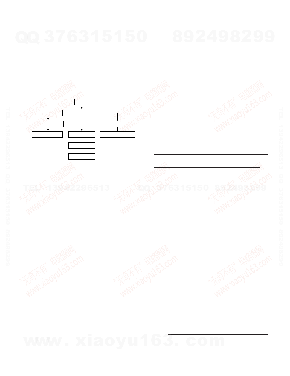
SECURITY CODE (GX-201REF2)
7
Q
Q
and GX-201RHF2.
● Security Function
the data from the immobilizer, which is sent from the vehicle,
and the data that are set beforehand.
chart below.
TEL 13942296513 QQ 376315150 892498299
● Code Confirmation Mode
tered or not in the audio unit.
TEL
rent mode.
• The registration condition of the Security code can be
• The Security code is not registered or when abnormalities
• When registering a Security code, the system will move to
● Non-Registration Mode
the Security code is not registered for an audio unit.
sible for an hour. Howe v er , there is a certain limitations placed
on the operation. Using this time, production and a variation
on the products will be conducted.
● Confirmation Mode
when the Security code is confirmed to be adjusted to in the
Code confirmation mode.
grated ECU on the vehicle side, it goes into the gateway. The
w
Immobi code sent to the audio unit by UART and the Security
code registered on the audio unit is compared.
3
The audio security system has been set for GX-201REF2
Security is released when an agreement is found between
The interrelationship in the security system is shown in the
Confirmation mode
OK
Normal operation
This mode is for judging whether the Security code is regis-
When the unit is reset, the operation will start from the Cur-
Thus system will move to the Non-registration mode, when
Even if the Security code is not resisted, operation is pos-
The system will automatically go into the Confirmation mode,
When the A/C ECU is obtained Through CAN from the Inte-
13942296513
grasped using the E2PROM.
detected with E2PROM, the system will move to Non-registration mode.
Confirmation mode.
w
w
6
Code confirmation mode
NG
Security mode
Delete mode
Re-Registration
.
xia
3
BU ON
1
5
Non-registrationRegistration
Non-registration mode
Registration mode
o
1
y
5
u
0
Q
Q
1
As a result of confirmation, if the code is judged to be authentic, the system goes into normal operation. However, if
the code is not judged to be authentic, then the system goes
into the Security mode.
● Security Mode
The system goes into the Security mode when the Immobi
code is not judged to be authentic when it is compared with
the Security code registered in the audio unit. When this happens, the unit can be operated for an hour. After the elapse of
an hour, the po wer on the unit is cut off and operation is f orcefully stopped.
Also, in the Non-registration mode, if an hour elapses, the
system will go into the Security mode. In the Security mode,
the power on the unit is cut off and operation is forcefully
stopped.
Note : When working on a unit to repair it, the repair would
should be conducted in the one hour effective time. After the
elapse of an hour, the power on the unit is cut off. If the power
is put on again, another hour will be given to operate on.
• Conditions of the audio unit during the Security mode
Power off.
7
3
Display light off.
Keys do not work (Except the EJECT Key).
Audio power off (No voice output).
Switching on TV sources not possible . ( Key operation from
the monitor not possible.)
Voice interruption/switching from NAVI and hands-free unit
not possible.
In the Security mode, the display is not lighted and when
there is an input from any of the key, “SECURITY” will be
displayed.
● Delete Mode
The system goes in the Delete mode, when the “Requesting Delete” condition of the Integrated ECU operating condition signal from the Integrated ECU is obtained by the A/C
ECU via low-speed CAN into the gateway and it is sent to the
audio unit via UART.
The Delete mode is positioned as a Test mode and detailed
input methods are not disclosed.
The Security code recorded into the E2PROM in the Registration mode and Re-registration mode is cleared in the Delete mode and non-registration condition is obtained.
Note : When a linked product is repaired, the security code
must be deleted when the repair work is completed.
6
3
For GX-201, in order to maintain the security, deletion is
only effective when selection monitor is used.
6
8
3
.
9
1
1
5
c
2
5
o
4
0
m
9
8
9
8
2
4
2
9
8
9
2
9
9
TEL 13942296513 QQ 376315150 892498299
9
13

GX-201KEF2/LEF2/REF2/SEF2
ADJUSTMENT
7
Q
Q
No. ITEM
CASSETTE DECK SECTION
[1] AZIMUTH
TEL 13942296513 QQ 376315150 892498299
[2]
3
PLAY BACK
LEVEL
6
SETTINGS SETTINGS
1
5
1
3
INPUT OUTPUT
TCC-153
10kHz
Connect a AC VR1 (L)
TCC-130 voltmeter to CN2 TAPE PLAY VR2 (R) 300mV
5
0
Connect a
AC voltmeter TAPE PLAY
to SP OUT becomes maximum
(X87) (X87)
TUNER
(RECEIVER)
SETTINGS
8
ALIGNMENT
Head Azimuth
9
POINTS
Screw
2
4
9
ALIGN FOR
Adjust the azimuth for each
Lch/Rch or FWD/RVS
8
2
9
9
TEL 13942296513 QQ 376315150 892498299
TEL
13942296513
Q
Q
3
7
6
3
1
5
1
5
0
8
9
2
4
9
8
2
9
9
14
w
w
w
.
xia
o
y
u
1
6
3
.
c
o
m
EDCBA
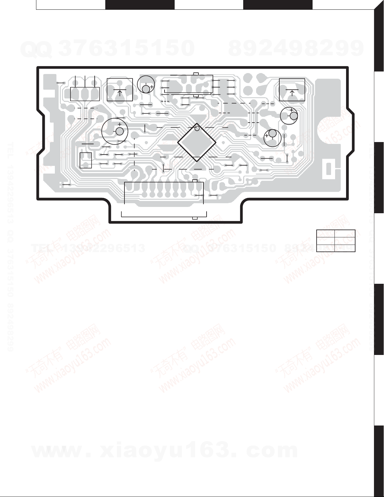
GX-201KEF2/LEF2/REF2/SEF2
PC BOARD (FOIL SIDE VIEW)
7
Q
Q
DOLBY NOISE REDUCTION UNIT X87-3052-70 (J74-1366-12)
TEL 13942296513 QQ 376315150 892498299
3
C25
C26
R
CN2
6
DOLBY
L
13
W10
W9
C6
R13
EB
Q1
R9
C24
3
C13
C17
VR1
C11
C20
C23
1
CN4
5
C15
R5
C7
C9
W8
R10
W7
1
C27
R11
5
C3
R3
W14
R8
10
11
R4
0
CN3
5
C4
20 21
C32
24
1
C29
IC1
C1
R1C2R2
1
C28
40
30
110
C31
31
W3
8
W1
W5
R7
C30
W6
9
C14
W2
W4
W12
2
W11
R12
C12
4
C5
DOLBY RDOLBY L
9
R6
C8
C16
8
VR2
2
9
1
9
2
TEL 13942296513 QQ 376315150 892498299
3
TEL
13942296513
Refer to the schematic diagram for the values of resistors and capacitors.
Q
Q
3
7
6
3
1
5
1
5
0
8
9
2
4
X87-3052-70
Ref No. Address
IC1 3C
Q1 3A
9
2
8
9
9
4
5
6
w
w
w
.
xia
o
y
u
1
6
3
.
c
o
m
7
15
 Loading...