

Kenwood EZ-500 Service manual

CD RECEIVER
Size AA battery
(Not supplied)
Plastic cabinet assy
(A02-2735-03)
Lever
(D10-4589-04)
x2
Screw set
(N99-1719-05)
Mounting hardware assy
(J22-0011-03)
CD MECHANISM EXTENSION CORD (24P) : W05-0934-00
MODEL TDF PANEL No. TDF NAME
EZ500 Y33-2110-11 TDF-EZ500
TDF PANEL INFORMATION
Panel assy
(A64-3418-12)
DC cord
(E30-6294-05)
Screw set
(N99-1730-15)
Remote controller assy (RC-505)
(A70-2059-05)
Escutcheon
(B07-3117-02)
EZ500
SERVICE MANUAL
© 2004-8 PRINTED IN JAPAN
B53-0196-00 (N) 793
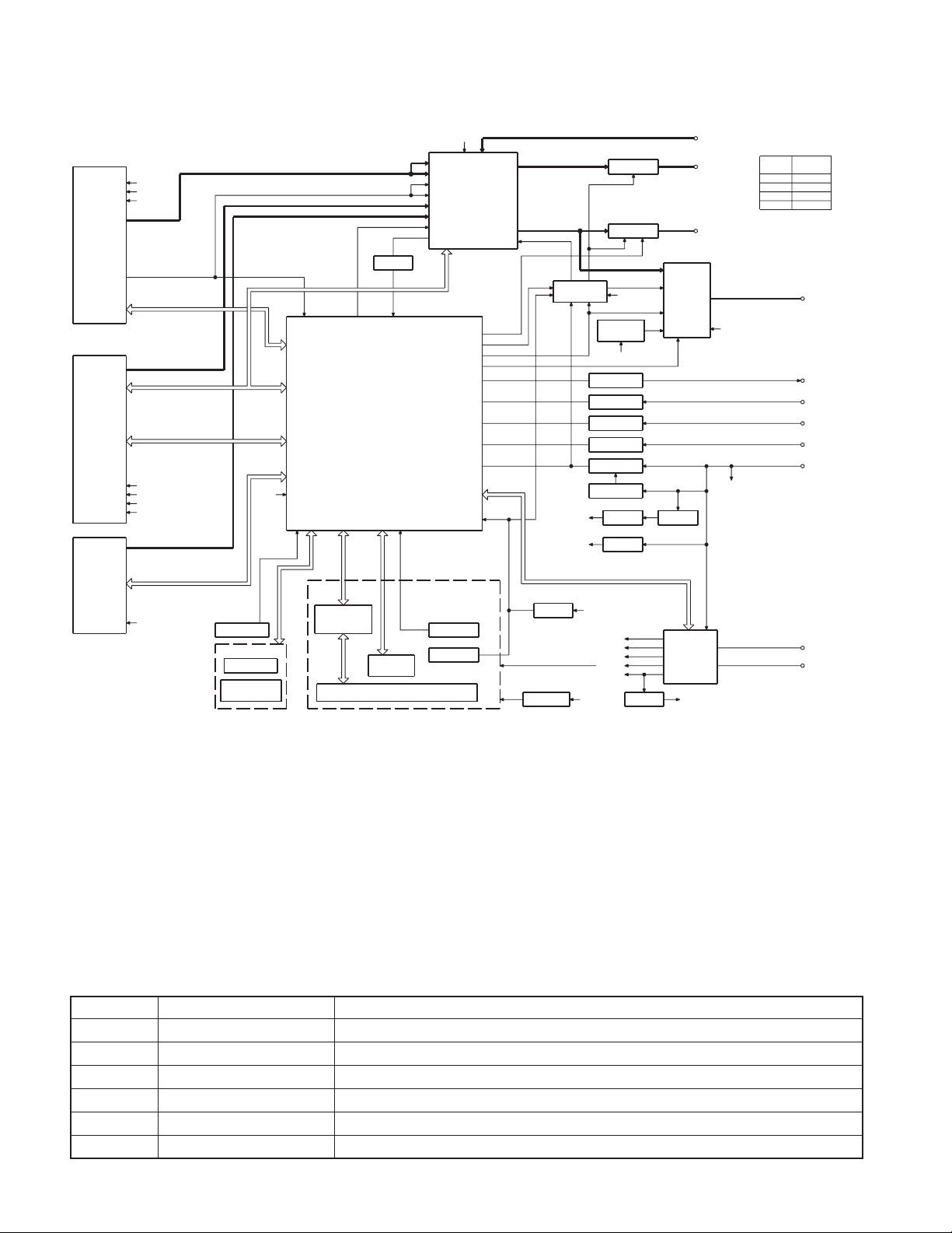
EZ500
BLOCK DIAGRAM
TUNER
AUDIO OUT
S-METER
PLL-DATA
PLL-CLK
IFC OUT
CD
MS DATA
MS CLK
M MUTE R
M MUTE L
M STOP
CH
CH CLK
DATA H
CH-CON
DATA C
CH RST
CH MUTE
SW1
SW2
SW3
SW4
M RST
LO/EJ
MOSW
REQ C
REQ H
DAUGHTER UNIT
AM+B
SW5V
A8V
SERVO+B
A8V
BU5V
CD MECHA+B
BACK UP
(X89- )
BU5V
PANEL DET
S1
EJECT SW
DSI
EJECT ILLUMI
IC1
S-METER
SYSTEM
MICROPROCESSOR
PANEL DET
EJECT
DSI
L CLK
L DATAS
IC1
LCD DRIVER
WITH
KEY MATRIX
SWITCH UNIT (X16- )
L CE
L DATAL
Q201
BUFFER
NOISE
VOL A
VOL B
ROTAR Y
ENCODER
LCD
REMO
S1
IC2
FM
AM
MP IN
LEVEL
CD
CH
AFS
QUAL
PRE MUTE
P-MUTE
EXT.AMP.CON
DIMMER
PHONE
ACC DET
B.U DET
REMOCON
RESET SW
A8V
E-VOL
MPX
MUTE
BEEP
PS1-0
PS1-1
PS1-2
PS2-0
PS2-2
RST
AUX IN
MUTE
DRIVER
Q351,352
Q355,356
THERMAL
PROTECT
EXT AMP
DIMMER
TEL MUTE
ACC DET
B.U DET
SERGE DET
Q21
SERVOSERVO+B
IC9
SW REG
BU5V
AM+B
FM+B
A8V
ILLUMI
BU5V
BU5V
PRE MUTE
PRE MUTE
BU5V
SW5V
Q32
Q31
Q3
Q2
Q1
Q4
SW 5V
FREE
AUX
&
FRONT
IC6
CD MECHA+B
IC8
RESET
IC2
Q152
PANEL 5V
IC4
Q22
SW 14V
IC3
POWER
IC
POWER
SUPPLY
IC
SW5V
PRE OUT
(REAR/NF)
PRE OUT
(FRONT)
BACK UP
BACK UP
MODE
CD,MP3
FM
AM
CH
OUTPUT
3600mV
1800mV
600mV
3600mV
SP OUT
EXT.AMP.CON
DIMMER
MUTE
ACC
BACK UP
ANT CON
P CON
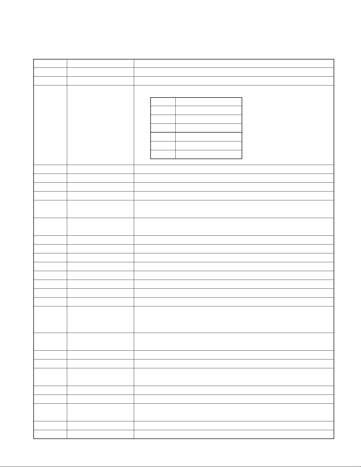
COMPONENTS DESCRIPTION
● SWITCH UNIT (X16-2960-10)
Ref. No. Application / Function Operation / Condition / Compatibility
IC1 LCD Driver Drives LCD
IC2 Remote Control IC Controls the unit
Q2 REMO ON SW The power supply of IC2 is turned on when base level goes “L”
Q3 Key Illumination SW (Red) Lights Red key-illumination when base level goes “H”
Q4 Key Illumination SW (Green) Lights Green key-illumination when base level goes “H”
Q5 Dimmer Control Lights LCD Back Light when base level goes “H”
2
COMPONENTS DESCRIPTION
● ELECTRIC UNIT (X34-3080-14)
Ref. No. Application / Function Operation / Condition / Compatibility
IC1 System µ-COM Controls FM/AM tuner, the changer, CD mechanism, Panel, volume and tone.
IC2 E.Vol & N.C.MPX Controls the source, volume, tone and FM multiplex detector.
Bu5V (5V), Audio8V (8V), FM+B (8V), AM+B (8V), P-CON, ANT-CON
SW1 OUT
1.5~3.0 Audio ON
IC3 Power Supply IC
IC4 Power IC Amplifies the front L/R and the rear L/R to 50W maximum.
IC6 Muting logic IC Controls logic for muting.
IC8 Reset IC “L” when detection voltage goes below 3.6V or less.
IC9 SW Regulator Power Supply for MP3
Q1 Serge Detection
Q2 BACK-UP Detection
Q3 ACC Detection “L” when Acc is present.
Q4 SW 5V ON when the base is “L”.
Q21 Servo Regulator
Q22 Servo SW
Q23 Control Power Supply IC
Q31 Dimmer Control Dimmer ON when the base is “H”.
Q32 EXT.AMP Control Controls Ext.AMP by pulse width.
Q41 SW Regulator Control
Q151 DSI Driver DSI turns off when the base is “H”.
Q152 Panel 5V SW
Q153,154 ILL Control ILL lights when the base of Q153 is “H”.
Q201 Noise buffer
Q350
Q351 Pre / NF Mute SW Mutes the Pre Rear Lch or NF Lch when the base is “H”.
Q352 Pre / NF Mute SW Mutes the Pre Rear Rch or NF Rch when the base is “H”.
Q354
Q355 Pre Mute SW Mutes the Front Lch when the base is “H”.
Q356 Pre Mute SW Mutes the Front Rch when the base is “H”.
Pre and NF Mute SW
(not always Pre and NF)
Pre and NF Mute SW
(not always Pre and NF)
3.5~5.0 Audio P-CON ON
7.0~ Audio P-CON, P-ANT ON
SW2 OUT
2.0~3.0 ILL FM ON
4.0~ ILL AM ON
“L” when the back-up voltage becomes more than 24V (momentary power down).
“H” when the back-up voltage becomes less than 24V.
“L” when B.u is present.
“H” when B.u is absent or momentary power down is detected.
DSI lights when the base is “L”.
DSI turns on and off when panel is taken off.
When the panel is attached, the base goes “L”, turning the Tr ON to supply 5V to the panel.
When panel is taken off, panel 5V cut off.
Drives the Pre and NF Mute sw (Q351,355) when the base is “L”.
Drives the Pre and NF Mute sw (Q352,356) when the base is “L”.
EZ500
3

EZ500
MICROCOMPUTER’S TERMINAL DESCRIPTION
● SYSTEM MICROCOMPUTER : UPD703030GC052 (X34 : IC1)
Pin No. Pin Name I/O Application
1 PLL CLK I/O CLK output terminal to F/E
2 Not used O
3PANEL-DET I Panel DET terminal No panel DET : L, Panel DET : H
4 IC2 SDA I/O DATA input/output terminal with E-VOL
5 IC2 SCL I/O CLK output terminal to E-VOL
6 VDD 7 VSS 8 FLIP-DET I Flip DET terminal L : Panel DET, H : Panel flippable
9 BEEP O BEEP output terminal
10 REMO I Remote control input
11,12 Not used O Destination other than E and E2
13 L CE O CE output terminal for LCD driver
14,15 Not used O Non variable illumination switch destination
EJECT KEY ILL, GUIDE ILL, FLIP-DET “H” and PANEL-DET is “L” : “H” / “L”
16 DSI I/O
DSI control terminal FLIP-DET “H” and PANEL-DET is “H” : “L”
17 DIM CON O Dimmer control terminal 50ms interval : “H” / “L”
18 TEST 19 ILL CON O During FLIP DET ILL+B OFF During FLIP DET “L” : H
20 VOL A I Volume key input When looking at VOL, also look at FLIPDET
21 VOL B I Volume key input When looking at VOL, also look at FLIPDET
22 MOSW O CD mechanism MOTOR IC SW Loading, Eject, Brake : H
23 LO/EJ I/O CD mechanism LOADING, EJECT switching STOP, Brake : Hi-Z, Loading : L, Eject : H
24 M STOP O STOP request to CD mechanism
25 M RST O Reset output terminal to CD mechanism Normal : H, Reset : L
26 MUTE I/O MUTE terminal Hi-Z : Mute ON, L : Mute OFF
27 LOE/LIM SW I CD DOWN SW DET terminal H : Chucking
28 M-MUTE L I MUTE request terminal from CD mechanism L : Mute request
29 M-MUTE R I MUTE request terminal from CD mechanism L : Mute request
30 PANEL 5V I/O Panel 5V control terminal
31 RESET I Normal : H, Reset : L
32 XT1 I 32kHz
33 XT2 I 32kHz
34 REGC - Connect 1µF condenser to GND
35 X2 I 20MHz
36 X1 I 20MHz
37 VSS 38 VDD 39 CLKOUT -
Truth
Processing Operation Description
value table
Panel DET : L, Detached, Momentary power down : H
4

EZ500
MICROCOMPUTER’S TERMINAL DESCRIPTION
Pin No. Pin Name I/O Application
40 IC2 TYPE1 I E-VOL setting switching terminal
41 IC2 TYPE0 I E-VOL setting switching terminal
42~44
45
46 SW5V I/O Control terminal for SW5V ON : L, OFF : Hi-Z
47,48
49~51
52 B.U-DET I Momentary power down DET terminal
53 ACC-DET I ACC DET terminal ACC DET : L, ACC no DET : H
54 DIMMER I Small DET terminal ON : L, OFF : H
55 BVDD 56 BVSS 57
58 (SVR) O POWER IC SVR control terminal Momentary power down : H
59 P-MUTE O POWER IC MUTE output terminal
60 P-STBY O POWER IC STBY output terminal When POWER IC ON : H, OFF : L
61 Not used O
62
63
64 AFS O Constant switching terminal at noise DET
65 O-DATA I/O Not used
66 O-CLK I/O Not used
67 O-CE I/O Not used
68 LX_RST O Reset output to external devices
69 LX_CON O Control output to external devices ON : H, OFF : L
70 AVCONT O AD reference voltage control output While in operation : H
71 AVDD 72 AVSS 73 AVREF - AD reference voltage control input Connect to 70 pin
74 PHONE I PHONE DET terminal
75 TYPE3 I Destination switching terminal
76~81 Not used I
82 S-METER I S-meter DET terminal
83 NOISE I FM noise DET terminal
84 IFC-OUT I F/E IFC OUT input terminal
TYPE2~TYPE0
CD MECHA+B
PS2-0, PS2-1
PS1-0~PS1-2
EXT AMP CON
PRE MUTE R
PRE MUTE L
I Destination switching terminal e
I/O Power supply control terminal for MP3 ON : L, OFF : Hi-Z
O Control terminal for power supply IC w
O Control terminal for power supply IC q
O
O Rch PRE MUTE output
O Lch PRE MUTE output
Truth
value table
BU DET : L, BU no DET (momentary power down) : H
During POWER OFF : L, During ALL OFF : L, When TEL MUTE : L
When momentary power down : L,
M-MUTE R : L (during CD), 2 zone : H fixed
When momentary power down : L,
M-MUTE L : L (during CD), 2 zone : H fixed
During FM seek and AF search : L, During reception : H
Normally : L,
System RST return, then after 400msec or more : H then L
TEL MUTE : 1V or lower,
NAVI MUTE : 2.5V or higher
Processing Operation Description
5
EZ500
MICROCOMPUTER’S TERMINAL DESCRIPTION
Pin No. Pin Name I/O Application
85 LX_MUTE I MUTE request from external devices H : MUTE ON, L : MUTE OFF
86 LX_REQ_M O Request output to external devices Request DET : L
87 Not used O Non RDS destination Output L fixed
88 LX_REQ_S I Request input from external devices Request DET : L
89 KEY-REQ I Communication request from LCD driver L : KEY input
90 LO.S SW I Loading start SW DET terminal Loading start : L
12cm DISC EJECT position DET SW terminal
91 12EJE SW I
12 or 8cm DET
92 EJECT I EJECT DET terminal L : KEY input
93 Not used O Output L fixed
94 LX_DATA_S I DATA input terminal from external devices
95 LX_DATA_M O DATA output terminal for external devices Last retention
96 LX_CLK I/O CLK input/output terminal with external devices
97 L DATAL I Data input from LCD driver
98 L DATAS O DATA output terminal to LCD driver
99 L CLK O CLK output terminal to LCD driver
100 PLL DATA I/O DATA input/output terminal with F/E
Truth
value table
12cm DISC : L
Processing Operation Description
Truth value table
q
PS1-0 PS1-1 PS1-2 AUDIO P-CON P-ANT
LLLOFF OFF OFF
H (L) L (H) L ON OFF OFF
HHLONONOFF
HHHONONON
w
PS2-0 PS2-1 ILLUMI FM+B AM+B
LLOFF OFF OFF
H (L) L (H) ON ON OFF
HHONOFF ON
e
MODEL
KDC-X579 K L L L
EZ500 K L L L
KDC-MP425 K H L L
KDC-MPV525 K L H L
KDC-MPV5025 K L L L
KDC-WV6027 E H L H
KDC-W6027 E L L H
KDC-W6027Y E L L H
KDC-MPV7026 M H H L
KDC-MP6026 M L H H
DESTINATION
012
TYPE
6

TEST MODE
EZ500
1. How to enter the test mode
• While holding the Preset 1 and Preset 3 keys, reset the unit.
2. How to exit from the test mode
• Reset the unit, ACC OFF, Power OFF, and Panel detached.
• (Note) The test mode cannot terminated by momentary
power down.
3. Initial status in the test mode
• Sources :All OFF
•Display :All segments are lit
•Volume :-10 dB (displayed as 30)
• Loudness :OFF
• CRSC :OFF regardless of the presence
of switching function
• SYSTEM Q : Flat.
• BEEP :When pressing any keys, the
buzzer generates a beep at any time
•AUX : ON
• MENU SYSTEM Q : OFF
•Variable model : Default is white
4. Special display in Tuner mode
When any of the following messages is displa yed in Tuner
mode, the front end may be abnormal.
• “TNE2P NG” : The EEPROM is set to the def ault (unstab le
values) because the F/E was shipped without passing
through the adjustment process, etc.
• “TNCON NG” : Communication with the F/E is not possible.
5. Forced switching of K3I
• Each press of the Preset 6 key in Tuner mode should switch
K3I from AUT O → Forced Wide → Forced Middle → Forced
Narrow → AUTO. The initial status is AUTO and the display shows these modes as follows.
•AUTO:FMA
•Forced Wide :FMW
•Forced Middle : FMM
•Forced Narrow: FMN
6. CD Receiver Test Mode Specification
• When resetting to start, forced ejection of CD is prohibited. When a CD is in place, the CD is not recognized
when reset.
• When the Track up key is pressed, the mechanism jumps
to the following trac k.
No.9 → No.15 → No.10 → No.11 → No.12 → No.13 →
No.22 → No.14 → No.9 (Return to the first track.)
• When the Track down key is pressed, the track goes down
by one from the currently played track.
• When the number of total tracks of the MP3 disc is less
than 9, 1st track is played.
• When a CD being played, by pressing Preset 1 key intermittently, the mechanism can be made to jump to Track
No. 28.
7. Audio-related specifications
•A short press of the Q key initiates the audio adjustment
mode.
• Pressing the ✽ key on the remote controller initiates the
audio adjustment mode.
•Fader is selected to the initial item.
•Continuous holding of a remote controller key is inhibited,
and workings are short press of any keys.
• Bass, Middle and Treble are adjusted in 3 steps of -8 / 0 /
+8 with the Track Up/Down keys (Default : 0).
• Balance is adjusted in 3 steps of L15 / 0 / R15 with the
Track Up/Down keys (Default : 0).
•Fader is adjusted in 3 steps of R15 / 0 /L15 with the Track
Up/Down keys (Default : 0).
• HPF is adjusted in 2 steps of OFF / 170Hz with the Track
Up/Down keys (Default : OFF).
• LPF is adjusted in 2 steps of OFF / 120Hz with the Track
Up/Down keys (Default : OFF).
• Bass f, Bass Q, Bass EXT, Middle f, Middle Q and Treble f
are not dealt with by the audio adjust.
8. Menu-related specifications
•A short press of the PLAY/PAUSE key initiates the Menu
mode.
• Pressing the DNPP key on the remote controller initiates
the Menu mode.
•Continuous holding of a remote controller key is inhibited,
and workings are short press of any keys.
• Contrast is adjusted in 3 steps of 0 / 5 / 10 with the Track
Up/Down keys (Default : 5).
9. Backup current measurement
•When the unit is reset while ACC is OFF (i.e. by turning
Back-Up ON), the MUTE terminal goes OFF in 2 seconds
in place of 15 second. (The CD mechanism is not activated at this time.)
7

EZ500
TEST MODE
10. Special display when the display is All ON
Pressing the Preset keys while the power is All OFF displays the following information.
1 key Version display (8 digits, Month/Day/Hour/Minute)
(Display) SYS xxxxxxxx
2 key Serial number display (8 digits)
(Display) SNo xxxxxxxx
3 key Short press : View power ON time.
(The All OFF period is not counted.)
2 seconds long press : Clear power ON time.
(Display) PonTim xxxxx Max. 60000 (hours)
4 key Short press : Display CD operation time.
2 seconds long press : Clear CD operation time.
(Display) CDTim xxxxx Max. 60000 (hours)
5 key Short press : Display CD ejection count.
2 seconds long press : Clear CD ejection count.
(Display) EjeCnt xxxxx Max. 60000 (times)
6 key Short press : Display Panel open/close count.
2 seconds long press : Clear Panel open/close count.
(Display) PnCnt xxxxxx Max. 600000 (times)
FM key Display ROM collection version.
(Display) ROM Rxxx Invalid : ROM R– – –
11. Other specifications
• Only during the changer operation, two-zone ON/OFF is
achieved by pressing Preset 1 key. When ON, P/S dot is
turned on all the time.
• No displays such as “CODE OFF/ON” during power ON.
• The line mute against times are 1 second from 10 seconds when starting the test mode.
• OEM display output is not stop if OEM display not connection on the test mode.
12. Switching the frequency span (K/M type)
• While holding the Preset 1 key and Preset 5 ke y, reset the
unit.
13. OEM compatible setting
(Electronic volume destination setting)
• Models equipped with S03F/E can become OEM model
compatible by using the No. 2 pin of the microcomputer.
The setting methods are shown below. For actual data
values, please refer to the Application Document IC2V-05.
IC2-TYPE0 IC2-TYPE1
(41 pin) (40 pin)
Low Low q Model on the market (default)
Low High w
High Low e
High High
Model on the market CRSC changed
OEM model compatible CRSC changed
r OEM model compatible CRSC and
de-emphasis changed
Contents
8
14. Security
• Forced Power ON mode (All models)
Even when the security (Simple security and Code security) is approved, resetting the unit while holding the Q key
and Preset 4 key makes it possible to turn the power ON
for 30 minutes. After 30 minutes have elapsed, it is not
possible to return to the previous condition unless the unit
is reset again. (Security code is doing not clear at this
mode. Put the power on fill-in.)
• Method of registration of the security code after
EEPROM (F/E) replacement (Code security model)
1. Enter the test mode. (See How to enter the test mode)
2. Press the MENU key to enter the MENU.
3. When the message “Security” is displayed, press and
hold the Track up/down keys for 1second to enter the
Security registration mode.
4. Enter the code using the FM/AM/Track up/Track down
keys.
• FM key : Number up
• AM key : Number down
•Track up key : Cursor right shift
•Track down key : Cursor left shift
5. Hold down the Track up key for at least 3 seconds and
the message, “RE-ENTER” appears , so once again enter the code according to Step 4 above.
6. Press and hold the Track up key for 3 seconds until “APPROVED” is displayed.
7. Exit from the test mode. (See How to exit from the test
mode)
(Note) All Clear is not applicable to the security code of
this model.
•
Method of clearing the simple security code (K type)
1. While the code entry is requested, press and hold the
Track up key for 3 seconds while holding the AUTO key
pressed. (– – – – will dissappear.)
2. Enter “KCAR” from the remote controller.
• Press the 5 key on the remotecontroller twice, then
press the Track up key. (This enters “K”)
• Press the 2 key on the remote controller 3 times, then
press the Track up key. (This enters “C”)
• Press the 2 key on the remote controller once, then
press the Track up key. (This enters “A”)
• Press the 7 key on the remote controller twice, then
press the Track up key. (This enters “R”)
3. Security function is canceled and the unit enters the All
OFF mode.
4. If you commit a mistake in the code entry, the unit enters the code request mode.
EDCBA
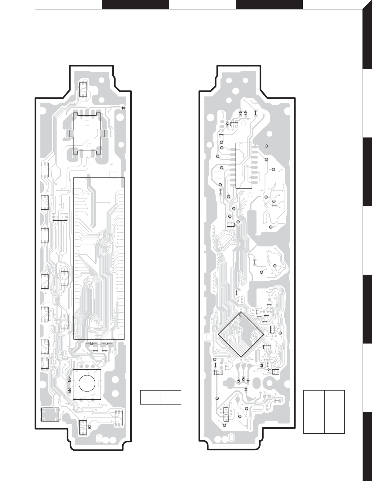
EZ500
PC BOARD
(COMPONENT SIDE VIEW) (FOIL SIDE VIEW)
SWITCH UNIT
X16-2960-10 (J76-0036-12)
AUTO
S2
S13
S11
S10
S7
SRC
ATT
VOLUME
S1
1
D1
ED1
73
SWITCH UNIT
X16-2960-10 (J76-0036-12)
D24
D23
R22
R21
D22
CP1
C11
C10
VOL A
VOL B
DI
ILL+B
R23
2
FLIP DET
16
CE
DO
CL
CP2
1
J1
15
PANEL 5V
RESET
KI3
KS4
ESD-GND
KI5
REMO
R11
1
2
3
4
AM
S9
S5
33
S6
564321
S4
S14
S8
RESET
FM
D2
C12
C13
AUTO
S15
34
25
R33
26
R32
Q5
DIMMER
R31
EB
R9
D3
X16-2960-10
Ref. No. Address
IC2 7A
IC2
1
3
S12
DISP
S3
2
4
Q4
DGND+ILL GND
EB
R14
EB
Q3
KI4
R12
R25
C1
R7
R6
R1
1
100
IC1
51
50
D28
D27
D26
KI2
KS2
C3
R2
C4
C2
R5
R4
R3
R16
76
CP4
KI1
C6
Q2
EB
D25
75
CP3
R8
D21
5
6
X16-2960-10
D29
KS3
KS5
R24
C7
R10
Ref. No. Address
IC1 5D
Q2 6D
Q3 7C
Q4 6C
Q5 6C
Refer to the schematic diagram for the values of resistors and capacitors.
7
9
F G H I J
8
R422
R54
C4
R
4
5
2
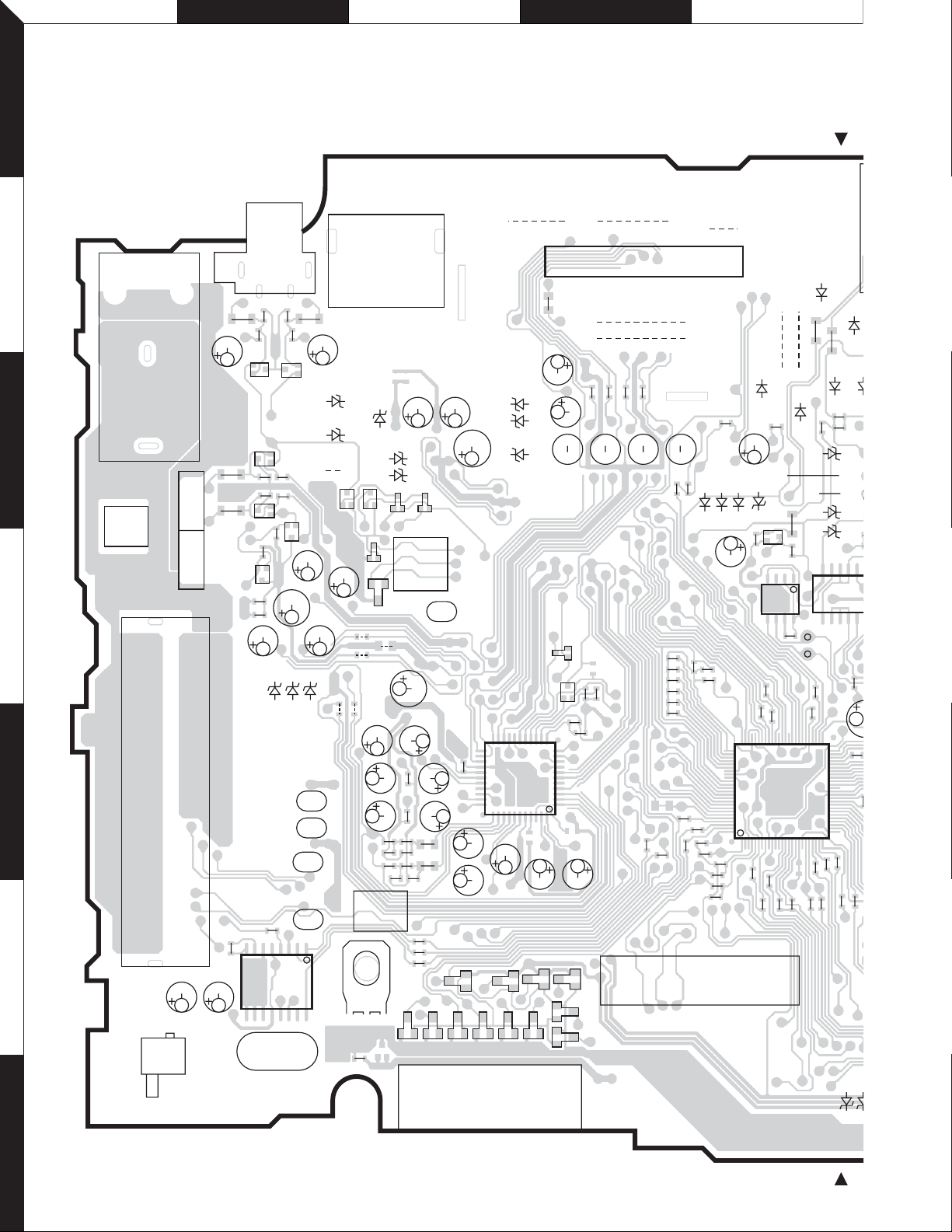
EZ500
1
PC BOARD (COMPONENT SIDE VIEW)
ELECTRIC UNIT X34-3080-14 (J74-1447-42)
W2
2
J3
R355
R351
EB
Q351
Q355
BE
R361R359
R362
R360
BE
R376
R377
EB
Q357
C355
C359
R356
R352
Q356
EB
R358
BE
Q352
Q358
C354
C358
C352
D308
D307
W1
Q350
C353
R357
C351
3
CN3
CN4
R363
1
R364
3
4
6
C360
R373
J4
L3
4
A1
1
J2
13 11 12 8 4 3 2
91067 5 1
C301
D309
D311
D310
BE
BE
Q354
D205 D204
CN6
3
D352
1
D351
W104
W101
W103
C211
L10
C302
C303
D301
D303
D304
224
125
TH1
C256
C255
C254
Q201
BE
W106
W105
D358
D357
D356
5
C221
L6
C220
L7
L8
CN5
L9
C116
24
6
C117 C115
C118
18
IC7
C216
1
2
R215
C222C224
R214R216
C223C225
C217
R211
R212
R213
R113
R112
R114
C219
C226
C227
C218
C210
C208
C207
D161
22
23
IC2
33
34
C209
D154
R203
C212
12
11
1
44
C202 C201
D153 D158
W3
IC4
W4
W5
R262/W204
R259/W201
R261/W203
D203
R204
R260/W202
C251 C252 C253
R253
R402
R403
R404
R406
R104
R102
R401
R405
R153
C213
R254
R152
CN2
23 1
24 2
C304
R154
R105
R103
R315
R407
R207
R208
R210
W6
C257
/W205
D270
C33
76
100
R209
D269
75
D252
R257
C258
D32
D271
Q31
EB
C32
41
IC10
R372
R371
R370
IC1
R163
R151
R155
R156
W7
D254
C7
R169
W8
85
R8
R34
R35
SDA
R158
D257
R37
R33
7
8
SCL
R36
C403
R60
R157
R31
D256
C31
R32
R9
51
50
26
251
R59
IC6
R56
R55
J1
D25
D31
D4
D2
D
R408
R2
R58
BU
C
R409
S1
169
X3
C502
P1
D162
D156D155D160D159D152
2
117
CN1
D157D151
18
D163 D
7
10
 Loading...