

Page 1

Use & Care Guide
English
Kenmore Elite
®
Dual Fuel Slide-in Range
P/N 318205875A (1009)
Sears Canada Inc., Toronto, Ontario,
Canada M5B 2B8
www.sears.ca
TM
Page 2

Table of Contents
Kenmore Elite Warranty .................................................... 2
IMPORTANT SAFETY INSTRUCTIONS ........................3-5
Product Record ....................................................................6
Serial Plate Location .......................................................... 6
Conversion to Liquefi ed Petroleum Gas .......................... 6
Feature at a Glance ...........................................................7
Before Setting Oven Controls ........................................... 8
Surface Cookware Recommendations ............................. 9
Before Setting Surface Controls ..................................... 10
Setting Surface Controls .............................................. 11-13
Oven Control Functions ................................................... 14
Getting Started ..................................................................15
Setting Oven Controls ................................................ 16-24
Warmer Drawer ..........................................................25-26
User Preferences ...............................................................27
Self-Cleaning Cycle ....................................................28-29
Care & Cleaning ......................................................... 30-33
Before You Call ...........................................................34-36
Protection Agreements .....................................................37
Sears Service .....................................................................38
Please carefully read and save these instructions
This Use & Care Manual contains general operating instructions for your appliance and feature information for
several models. Your product may not have all the described features. The graphics shown are representative. The
graphics on your appliance may not look exactly like those shown. Common sense and caution must be practiced
when installing, operating and maintaining any appliance.
Kenmore Elite Warranty
When installed, operated and maintained according to all instructions supplied with the product, if this appliance fails due to a
defect in material and workmanship within one year from the date of purchase, call 1-800-4-MY-HOME® to arrange for free repair.
This warranty applies for only 90 days from the date of purchase if this appliance is ever used for other than private family purposes.
This warranty covers only defects in material and workmanship. Sears will NOT pay for:
1. Cracks in a ceramic glass cooktop that are not a result of thermal shock.
2. Stains and scratches on a ceramic glass cooktop resulting from accident or improper operation or maintenance.
3. Expendable items that can wear out from normal use, including but not limited to fi lters, belts, light bulbs, and bags.
4. A service technician to instruct the user in correct product installation, operation or maintenance.
5. A service technician to clean or maintain this product.
6. Damage to or failure of this product if it is not installed, operated or maintained according to the all instructions
supplied with the product.
7. Damage to or failure of this product resulting from accident, abuse, misuse or use for other than its intended purpose.
8. Damage to or failure of this product caused by the use of detergents, cleaners, chemicals or utensils other than those
recommended in all instructions supplied with the product.
9. Damage to or failure of parts or systems resulting from unauthorized modifi cations made to this product.
Disclaimer of implied warranties; limitation of remedies
Customer’s sole and exclusive remedy under this limited warranty shall be product repair as provided herein. Implied
warranties, including warranties of merchantability or fi tness for a particular purpose, are limited to one year or the shortest
period allowed by law. Sears shall not be liable for incidental or consequential damages. Some states and provinces do not
allow the exclusion or limitation of incidental or consequential damages, or limitation on the duration of implied warranties
of merchantability or fi tness, so these exclusions or limitations may not apply to you.
This warranty applies only while this appliance is used in the United States or Canada.
This warranty gives you specifi c legal rights, and you may also have other rights which vary from state to state.
Sears Brands Management Corporation, Hoff man Estates, IL 60179 - Sears Canada Inc., Toronto, Ontario, Canada M5B 2B8
Printed in Canada
2
Page 3

IMPORTANT SAFETY INSTRUCTIONS
Read all instructions before using this appliance.
Save these instructions for future reference.
This manual contains important safety symbols and instructions. Please pay attention
to these symbols and follow all instructions given.
This symbol will help alert you to situations that may cause serious bodily harm, death
or property damage.
This symbol will help alert you to situations that may cause bodily injury or property damage.
If the information in this manual is not
followed exactly, a fi re or explosion may result causing
property damage, personal injury or death.
FOR YOUR SAFETY:
— Do not store or use gasoline or other fl ammable
vapors and liquids in the vicinity of this or any
other appliance.
— WHAT TO DO IF YOU SMELL GAS:
• Do not try to light any appliance.
• Do not touch any electrical switch; do not use
any phone in your building.
• Immediately call your gas supplier from a
neighbor’s phone. Follow the gas supplier’s
instructions.
• If you cannot reach your gas supplier, call the
fi re department.
— Installation and service must be performed by a
qualifi ed installer, servicer or the gas supplier.
be secured by properly installed anti-tip
bracket provided with the appliance. To
check if the bracket is installed properly;
grasp the top rear of the appliance and
carefully attempt to tilt it forward. Refer
to the Installation Instructions for proper
anti-tip bracket installation.
• All appliances can tip.
• Injury to persons could
result.
• Install anti-tip bracket
packed with unit.
• See Installation
Instructions.
To reduce the risk of
tipping, the appliance must
• Remove all tape and packaging before using
the appliance. Destroy the carton and plastic
bags after unpacking the appliance. Never
allow children to play with packaging material.
• Proper Installation. Be sure your appliance
is properly installed and grounded by a
qualifi ed technician in accordance with
National Fuel Gas Code ANSI Z223.-latest
edition, or in Canada CAN/CGA B149.1, and
CAN/CGA B149.2, and the National Electrical
Code ANSI/NFPA No.70- latest edition, or in
Canada CSA standard, Canadian electrical
Code, part 1, and local code requirements.
Install only per installation instructions provided
in the literature package for this appliance.
• In case of an emergency, know how to
disconnect the electrical power to the
appliance at the circuit breaker or fuse box.
• User Servicing. Do not repair or replace
any part of the appliance unless specifi cally
recommended in the manuals. All other
servicing should be done only by a qualifi ed
technician. This may reduce the risk of personal
injury and damage to the range. Sears Parts &
Repair is the recommended repair service for
this appliance.
• Never modify or alter the construction of a
range by removing leveling legs, panels, wire
covers or any other part of the product.
• Air curtain or other overhead hoods, which
operate by blowing a downward air fl ow on
to a range, shall not be used in conjunction
with gas ranges other than when the hood
and range have been designed, tested and
listen by an independent test laboratory for
use in combination with each other.
NEVER use this appliance as a
space heater to heat or warm the room. Doing so
may result in carbon monoxide poisoning.
3
Page 4

IMPORTANT SAFETY INSTRUCTIONS
NEVER cover any slots, holes or
passages in the oven bottom or cover an entire
rack with materials such as aluminum foil. Doing
so blocks air fl ow through the oven and may
cause carbon monoxide poisoning. Aluminum foil
linings may trap heat, causing a fi re hazard.
• Do Not Use Water or Flour on Grease Fires.
Smother the fi re with a pan lid, or use baking
soda, a dry chemical or foam-type extinguisher.
• When heating fat or grease, watch it closely.
Fat or grease may catch fi re if allowed to
become too hot.
Stepping, leaning, sitting or pulling
down on the door of this appliance can result
in serious injuries and may also cause damage
to the appliance. Do not allow children to climb
or play around the appliance. The weight of a
child on an open door may cause the range to tip,
resulting in serious burns or other injury.
Do not use the ovens for storage.
Do not store items of interest to
children in the cabinets above an appliance.
Children climbing on the appliance to reach
items could be seriously injured.
• Storage on Appliance. Flammable materials
should not be stored in an oven, near surface
burners. This includes paper, plastic and cloth
items, such as cookbooks, plasticware and
towels, as well as fl ammable liquids. Do not
store explosives, such as aerosol cans, on or
near the appliance.
• Do not leave children alone. Children should
not be left alone or unattended in the area
where an appliance is in use. They should
never be allowed to sit or stand on any part of
the appliance.
• DO NOT TOUCH SURFACE BURNERS, AREAS
NEAR THESE BURNERS OR INTERIOR
SURFACES OF THE OVEN. Both surface and
oven burners may be hot even though fl ames
are not visible. Areas near surface burners may
become hot enough to cause burns. During and
after use, do not touch, or let clothing or other
fl ammable materials touch these areas until
they have had suffi cient time to cool. Among
these areas are the cooktop, surface facing the
cooktop, the oven vent openings and surfaces
near these openings, oven door and window.
• Use Only Dry Potholders. Moist or damp
potholders on hot surfaces may result in burns
from steam. Do not let the potholders touch hot
heating burners. Do not use a towel or other
bulky cloth instead of a potholder.
• Do Not Heat Unopened Food Containers.
Buildup of pressure may cause the container
to burst and result in injury.
• Remove the oven door from any unused
appliance if it is to be stored or discarded.
IMPORTANT—Do not attempt to operate the
appliance during a power failure. If power fails,
always turn off the appliance. If the appliance
is not turned off and the power resumes, it will
begin to operate again. Once the power resumes,
reset the clock and oven function.
Electronic controllers can be
damaged by cold temperatures. When you use
your appliance for the fi rst time, or if it has
not been used for a long period of time, make
sure that it has been exposed to a temperature
above 0°C/32°F for at least 3 hours before
connecting it to the power supply.
IMPORTANT INSTRUCTIONS FOR USING
YOUR COOKTOP
Use Proper Flame Size. Adjust fl ame
size so it does not extend beyond the edge of the
utensil. The use of undersized utensils will expose a
portion of the burner fl ame to direct contact and
may result in ignition of clothing. Proper relationship
of utensil to fl ame will also improve effi ciency.
• Know which knob controls each surface
burner. Place a pan of food on the burner
before turning it on, and then turn the burner
off before removing the pan.
• Wear Proper Apparel. Loose-fi tting or hanging
garments should never be worn while using
the appliance. Do not let clothing or other
fl ammable materials contact hot surfaces.
• Always turn knob to the full LITE position
when igniting top burners. Visually check that
burner has lit. Then adjust the fl ame so it does
not extend beyond the edge of the utensil.
4
Page 5

IMPORTANT SAFETY INSTRUCTIONS
• Utensil handles should be turned inward and
not extend over adjacent surface burners. To
reduce the risk of burns, ignition of fl ammable
materials, and spillage due to unintentional
contact with the utensil, the handle of the
utensil should be positioned so that it is turned
inward, and does not extend over adjacent
surface burners.
• Never leave surface burners unattended at
high heat settings—Boilovers cause smoking
and greasy accumulations that may ignite, or
a pan that has boiled dry may melt.
• Protective liners—Do not use aluminum foil
to line surface burner pans, or oven bottom,
except as suggested in this manual. Improper
installation of these liners may result in risk of
electric shock, or fi re.
• Glazed cooking utensils—Only certain types
of glass, glass/ceramic, ceramic, earthenware,
or other glazed utensils are suitable for cooktop
service without breaking due to the sudden
change in temperature. Check the manufacturer’s
recommendations for cooktop use.
IMPORTANT INSTRUCTIONS FOR USING
YOUR OVEN
• Use Care When Opening an Oven Door—Stand
to the side of the appliance when opening the
door of a hot oven. Let hot air or steam escape
before you remove or replace food in the oven.
• Keep Oven Vent Ducts Unobstructed. The oven
is vented at the center trim above the oven and
below the console. Touching the surfaces in this
area when the oven is operating may cause
severe burns. Also, do not place plastic or heatsensitive items near the oven vent. These items
could melt or ignite.
• Placement of Oven Racks. Always place
oven racks in desired location while oven is
cool. Remove all utensils from the rack before
removing rack. If rack must be moved while
oven is hot, use extreme caution. Use pot
holders and grasp the rack with both hands to
reposition. Do not let pot holders contact the
hot oven burner or interior of the oven.
• Do not use the broiler pan without its insert. The
broiler pan and grid allow dripping fat to drain
and be kept away from the high heat of the broiler.
• Do not cover the broiler grid or oven bottom
with aluminum foil. Exposed fat and grease
could ignite.
• Do not touch a hot oven light bulb with a
damp cloth. Doing so could cause the bulb to
break. Disconnect the appliance or shut off the
power to the appliance before removing and
replacing the bulb.
IMPORTANT INSTRUCTIONS FOR CLEANING
YOUR RANGE
• Clean the appliance regularly to keep all
parts free of grease that could catch fi re.
Exhaust fan ventilation hoods and grease fi lters
should be kept clean. Do not allow grease to
accumulate. Greasy deposits in the fan could
catch fi re. Refer to the hood manufacturer’s
instructions for cleaning.
• Kitchen cleaners and aerosols—Always follow
the manufacturer’s recommended directions for
use. Be aware that excess residue from cleaners
and aerosols may ignite causing damage and
injury.
• Clean in the self-cleaning cycle only the parts
of the appliance listed in this Use & Care
Guide. Before using the self-cleaning cycle of
the appliance, remove the broiler pan and any
utensils stored in the appliance.
• Do not clean the oven door gasket. The door
gasket is essential for a good seal. Care should be
taken not to rub, damage or move the gasket.
• Do not use oven cleaners. No commercial oven
cleaner or oven liner protective coating of any
kind should be used in or around any part of the
appliance
The health of some birds is extremely
sensitive to the fumes given off during the self-
clean cycle of any oven. Move birds to another
well ventilated room.
SAVE THESE INSTRUCTIONS FOR FUTURE REFERENCE.
5
Page 6
Product Record
In this space below, record the date of purchase, model and
serial number of your product. You will fi nd the model and
serial number printed on the serial plate.
Model No. ______________________________________
Serial No. _______________________________________
Date of purchase ________________________________
Save these instructions and your sales receipt for future
reference.
790.
Serial Plate Location
You will fi nd the model and serial number printed on the
serial plate. The serial plate is located along the interior side
trim and visible when the oven door is opened.
Remember to record the serial number for future reference.
Serial Plate Location
Conversion to Liquefi ed
Petroleum Gas (or L.P. Gas)
This natural gas range is designed to allow for conversion to
Liquefi ed Petroleum (L.P.) Gas.
Only a qualifi ed service agent should perform the L. P.
conversion. Contact the local gas provider for conversion.
The L. P. Conversion Kit is supplied with this range and is
located on the main back of the range. The kit contains
installation instructions which must be read before and
followed carefully when installing the kit.
To avoid serious injury, any additions,
changes or conversions required in order for this appliance
to satisfactorily meet the application needs must be made
by a qualifi ed service agent.
6
Page 7

Features at a Glance
2
Your Range includes:
1. Electronic oven control with kitchen timer.
2. Left front burner valve and knob.
3. Left rear bridge burner valve and knob.
4. Warmer drawer control.
5. Center rear burner valve and knob.
6. Right rear burner valve and knob.
7. Right front burner valve and knob.
3
4
1
5 6
7
9
8
10
8. Self-clean door latch.
9. Oven vent.
10. Broil element.
11. Self-cleaning convection oven interior.
12. Dual convection bake cooking system.
13. Adjustable interior porcelain oven rack(s).
14. Large 1-piece oven door handle.
15. Full width oven door with window.
16. Warmer drawer.
17. Cast iron grates.
18. 21 000 BTU bridge burner.
19. 9 500 BTU regular burner.
20. 5 000 BTU simmer burner.
21. 600 to 18 000 BTU dual burner.
22. Deep drawn cooktop.
17
18
20
14
14
16
11
12
13
15
19
NOTE: The features of your range may vary according to
model type & color.
21
22
7
Page 8
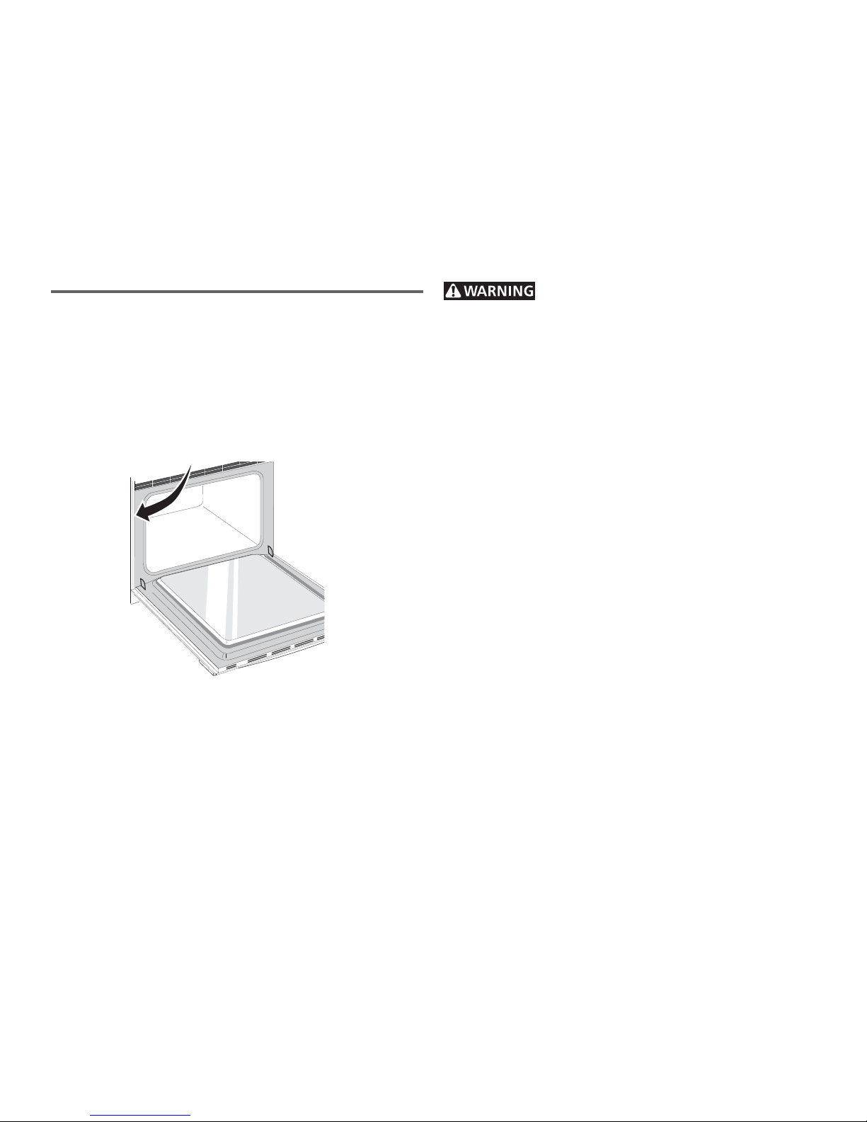
Before Setting Oven Controls
Oven Vent Location
The oven is vented through its upper front frame. When
the oven is on, warm air is released through the vent. This
venting is necessary for proper air circulation in the oven
and good baking results. Do not block oven vent.
Oven Vent
Some
models are equipped
with a blower which
runs in baking and
self-cleaning mode
to keep all internal
components at a cool
temperature. The
blower may keep running even if the oven
has been turned off ,
until the components
have cooled down.
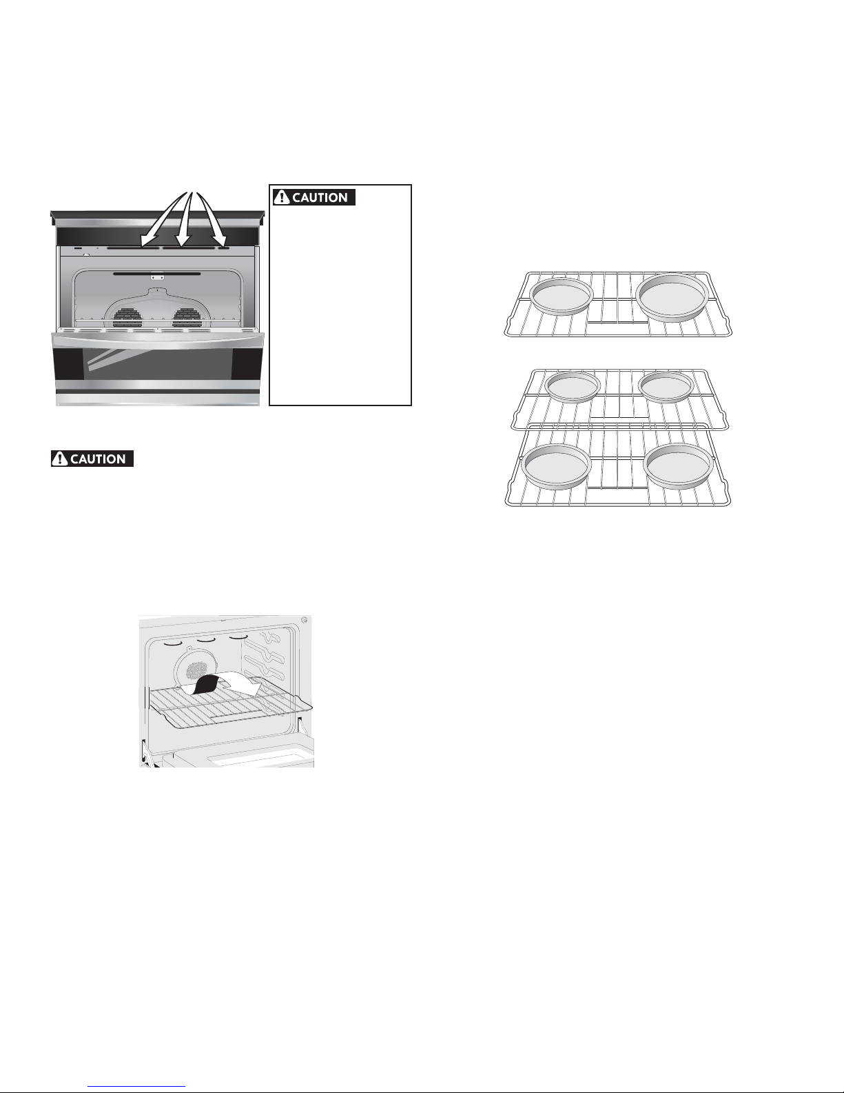
Arranging Oven Racks
Always use pot holders or oven mitts when
adjusting the oven racks. Wait until the oven has completely
cooled if possible. Oven racks may be HOT and cause burns.
To remove an oven rack, pull the rack forward until it stops.
Lift up front of rack and slide out.
Air Circulation in the Oven
If using 1 rack, place in center of oven. If using multiple
racks, stagger cookware as shown.
For best air circulation and baking results allow 2-4” (5-10
cm) around the cookware for proper air circulation and be
sure pans and cookware do not touch each other, the oven
door, sides or back of the oven cavity. The hot air must
circulate around the pans and cookware in the oven for even
heat to reach around the food.
1 Oven Rack
Multiple Oven Racks
To replace an oven rack, fi t the rack onto the guides on the
oven walls. Tilt the front of the rack upward and slide the
rack back into place.
8
Page 9

Surface Cookware Recommendations
Use Proper Cookware
Cookware should have fl at bottoms that make good contact
with the cooktop grate. Check for fl atness by rotating a
ruler across the bottom of the cookware (See Figure 1). Be
sure to follow the recommendations for using cookware as
shown in Figure 2.
Note: The size and type of cookware used will infl uence the
setting needed for best cooking results.
Note: Always use a utensil for its intended purpose. Follow
manufacturer's instructions. Some utensils were not made to
be used in the oven or on the cooktop.
Figure 1
CORRECT
• Flat bottom and straight
sides.
• Tight fi tting lids.
• Weight of handle does
not tilt pan. Pan is well
balanced.
• Pan sizes match the
amount of food to be
prepared.
• Made of material that
conducts heat well.
• Easy to clean.
INCORRECT
• Curved and warped pan bottoms.
• Pan overhangs unit by more
than 2.5 cm (1”).
• Heavy handle tilts pan.
• Flame extends beyond unit.
Cookware Material types
The cookware material determines how evenly and quickly
heat is transferred from the surface unit to the pan bottom.
The most popular materials available are:
ALUMINUM - Excellent heat conductor. Some types of food
will cause it to darken (Anodized aluminum cookware resists
staining & pitting).
COPPER - Excellent heat conductor but discolors easily.
STAINLESS STEEL - Slow heat conductor with uneven
cooking results. Is durable, easy to clean and resists staining.
CAST IRON - A poor heat conductor however will retain
heat very well. Cooks evenly once cooking temperature is
reached.
PORCELAIN-ENAMEL on METAL - Heating characteristics
will vary depending on base material.
GLASS - Slow heat conductor.
Using a Wok (not supplied)
Woks with fl at bottoms suitable for use on your cooktop
are available in most cookshop or hardware stores. Roundbottomed woks (with a support ring that does not extend
beyond the burner unit) may also be used. The metal ring
was designed to support the wok safely when it is fi lled with
large amounts of liquids (soup making) or fat (frying).
Wire trivets: Do not use wire trivets. Cookware bottoms must
be in direct contact with the grates.
Figure 2
* Specialty pans such as lobster pots, griddles and pressure
cookers may be used but must conform to the above
recommended cookware requirements.
DO NOT use a wok if it is equipped with
a metal ring that extends beyond the
burner unit. Because this ring traps heat,
the surface unit and cooktop surface
could be damaged.
9
Page 10
Before Setting Surface Controls
g
Check Burner Cap Placement Before Operating
the Surface Burners
To prevent fl are-ups and avoid creation of harmful by-
products, do not use the cooktop without all burner caps
properly installed to insure proper ignition and gas fl ame size.
It is very important to be sure that all surface burner caps
and burner grates are properly installed and in the correct
locations BEFORE operating the cooktop burners.
Remember:
• Always keep surface burner caps in place whenever using
a surface burner.
• When placing the burner caps, be sure that all burner caps
are seated fi rmly and rest level on top of burner heads.
• For proper fl ow of gas and ignition of burners DO NOT
allow spills, food, cleaning agents or any other material
to enter the gas orifi ce port opening.
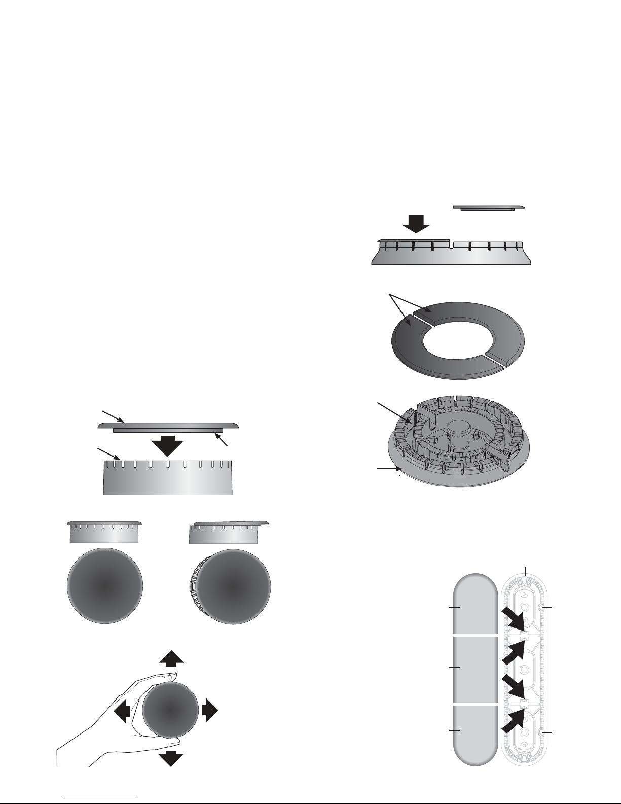
Round Style Burners
The burner cap lip (See Fig. 1) should fi t snug into the center
of burner head and rest level. Refer to Figs. 2 & 3 for
correct and incorrect burner cap placement. Once in place,
you may check the fi t by gently sliding the burner cap
from side to side (Fig. 4) to be sure it is centered and fi rmly
seated. When the burner cap lip makes contact inside the
center of the burner head you will be able to feel it. Please
note that the burner cap should NOT move off the center of
the burner head when sliding from side to side.
Burner Cap
Double Ring Style Burners
The Double Ring burner only operates properly with two
burner caps in place. Be sure the burner cap lips are
positioned facing down towards the burner head (Fig. 5)
and into the recessed areas (Fig. 6) on each side of the
burner head. Be sure both burner caps are seated fi rmly and
rest level on the burner head before operating.
Check the fi t for each cap using the same method for the
round burner caps by gently sliding each cap from side to
side. Please note that the burner cap lips should NOT move
out of recessed areas of the burner head.
Fig. 5
Burner Caps
Recessed area
Burner Head
Correct Burner Cap
Placement
Fig. 2
Fig. 1
Burner Cap Lip
Incorrect Burner Cap
Placement
Fig. 3
Fi
. 4
Burner Head
Fig. 6
Bridge Style Burners
Install Burner Caps, these include one Bridge Burner Center
Cap (rectangular shaped) and the two Bridge Burner End
Caps (The Bridge
Bridge Burner Head
Burner End Caps will
fi t either the front or
rear Bridge Burner
Head locations).
Make sure that the
lips located under
Bridge
Burner
End
Cap
the Bridge Burner
Caps fall into the
slots located in the
Bridge Burner Head
(See arrows in Figure
Bridge
Burner
Center
Cap
7) and that all the
Bridge Burner Caps
lie fl at and evenly
on the Bridge Burner
Head.
10
Bridge
Burner
End
Cap
Fig. 7
Igniter
Hole
Igniter
Hole
Page 11
Setting Surface Controls
RIGHT
WRONG
r
Setting Proper Surface Burner Flame Size
For most cooking, start on the highest control setting and
then turn to a lower one to complete the process. Use the
recommendations below as a guide for determining proper
fl ame size for various types of cooking. The size and type
of utensil used and the amount of food being cooked will
infl uence the setting needed for cooking.
*Flame Size Type of Cooking
High Flame Start most foods; bring water to a boil;
pan broiling.
Medium Flame Maintain a slow boil; thicken sauces,
gravies; steaming.
Low Flame Keep foods cooking; poach; stewing.
*These settings are based on using medium-weight metal
or aluminum pans with lids. Settings may vary when using
other types of pans. The color of the fl ame is the key to
proper burner adjustment. A good fl ame is clear, blue and
hardly visible in a well-lighted room. Each cone of fl ame
should be steady and sharp. Clean burner if fl ame is yellow-
orange.
Regardless of size, always select cookware that is suitable
for the amount and type of food being prepared. Select a
burner and fl ame size appropriate to the pan. Never allow
fl ames to extend beyond the outer edge of the pan.
Never extend the fl ame beyond the outer edge of the
utensil. A higher fl ame wastes heat and energy and
increases your risk of being burned by the fl ame (Figure 1).
Proper
fl ame
size
Figure 1
For deep fat frying, use a thermometer and adjust the
surface control knob accordingly. If the fat is too cool, the
food will absorb the fat and be greasy. If the fat is too
hot, the food will brown so quickly that the center will be
undercooked. Do not attempt to deep fat fry too much food
at once as the food will neither brown nor cook properly.
Imprope
fl ame
size
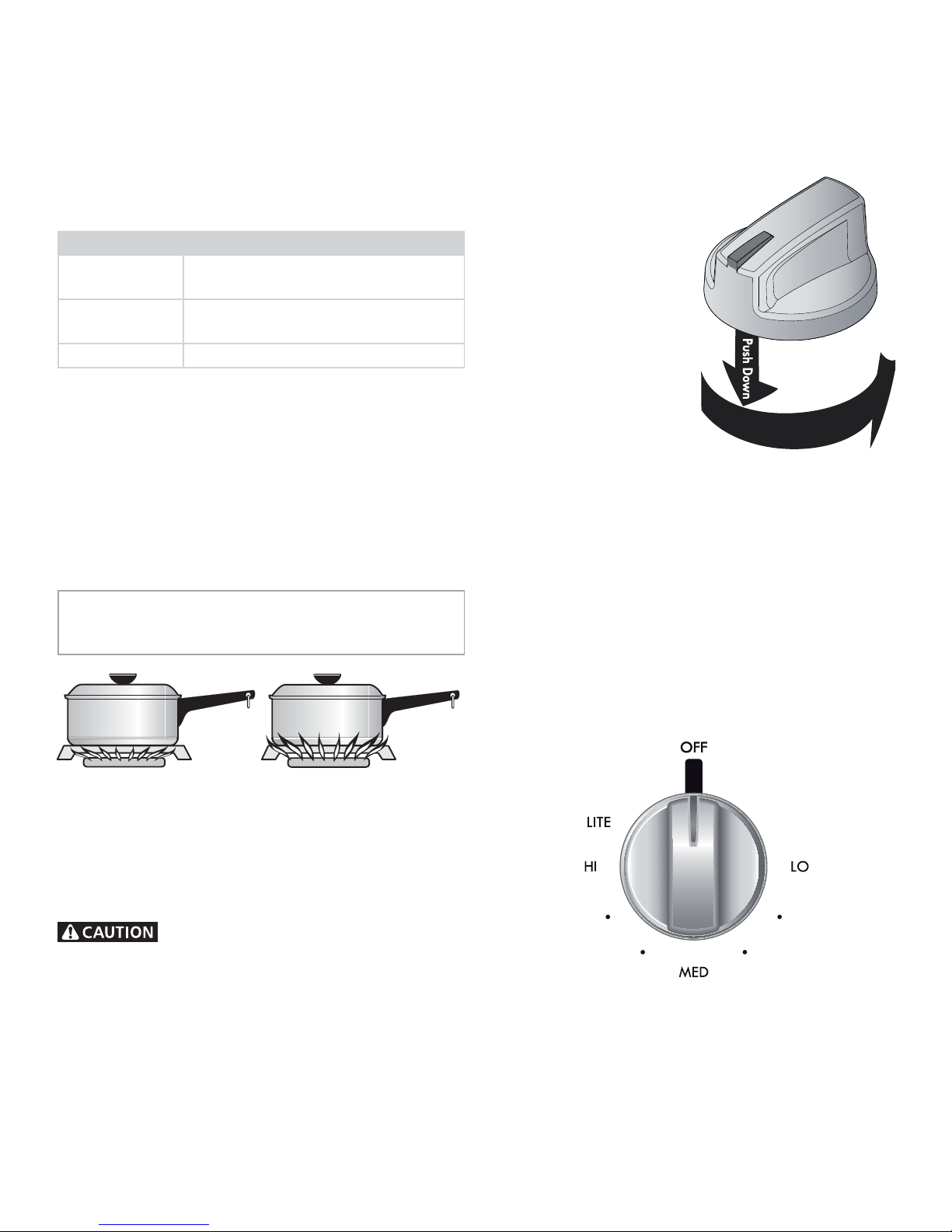
Setting the Regular or Simmer Burners
1. Place cooking utensil on surface burner.
2. Push the surface control knob down and turn
counterclockwise out of
the OFF position (See
Figure 2).
3. Release the knob and
rotate to the LITE
position.
4. Visually check that the
burner has a fl ame.
5. Once the burner is
lit, continue to turn
counterclockwise to
the desired fl ame size.
The control knobs do
not have to be set at
a particular setting.
Use the knob indicator
settings to adjust the
fl ame as needed.
Important notes:
• DO NOT cook with the surface control knob left in the
LITE position. (The electronic ignitor will continue to spark
if the control knob setting remains in the LITE position).
• When setting any surface control knob to the LITE
position, all electronic surface ignitors will spark at the
same time. However, only the surface burner you are
setting will ignite.
• NEVER place or straddle a cooking utensil over two
diff erent surface cooking areas at the same time. This
can cause uneven heating results.
T
u
r
n
C
o
u
Figure 2
o
n
l
t
c
e
r
e
s
i
w
k
c
Do not place items such as aluminum
foil, salt and pepper shakers, spoon holders or plastic
wrappings on top of the range when it is in use. These
items could melt or ignite. Potholders, towels or wood spoons
could catch fi re if placed too close to a fl ame.
Manual Lighting
In the event of an electrical power outage, the surface
burners can be lit manually. To light a surface burner, hold
a lit match to the burner head, then slowly turn the surface
control knob to LITE. After burner lights push in and turn
knob to desired setting. Use caution when lighting surface
burners manually.
Figure 3 - Regular or Simmer Burner Control
11
Page 12
Setting Surface Controls
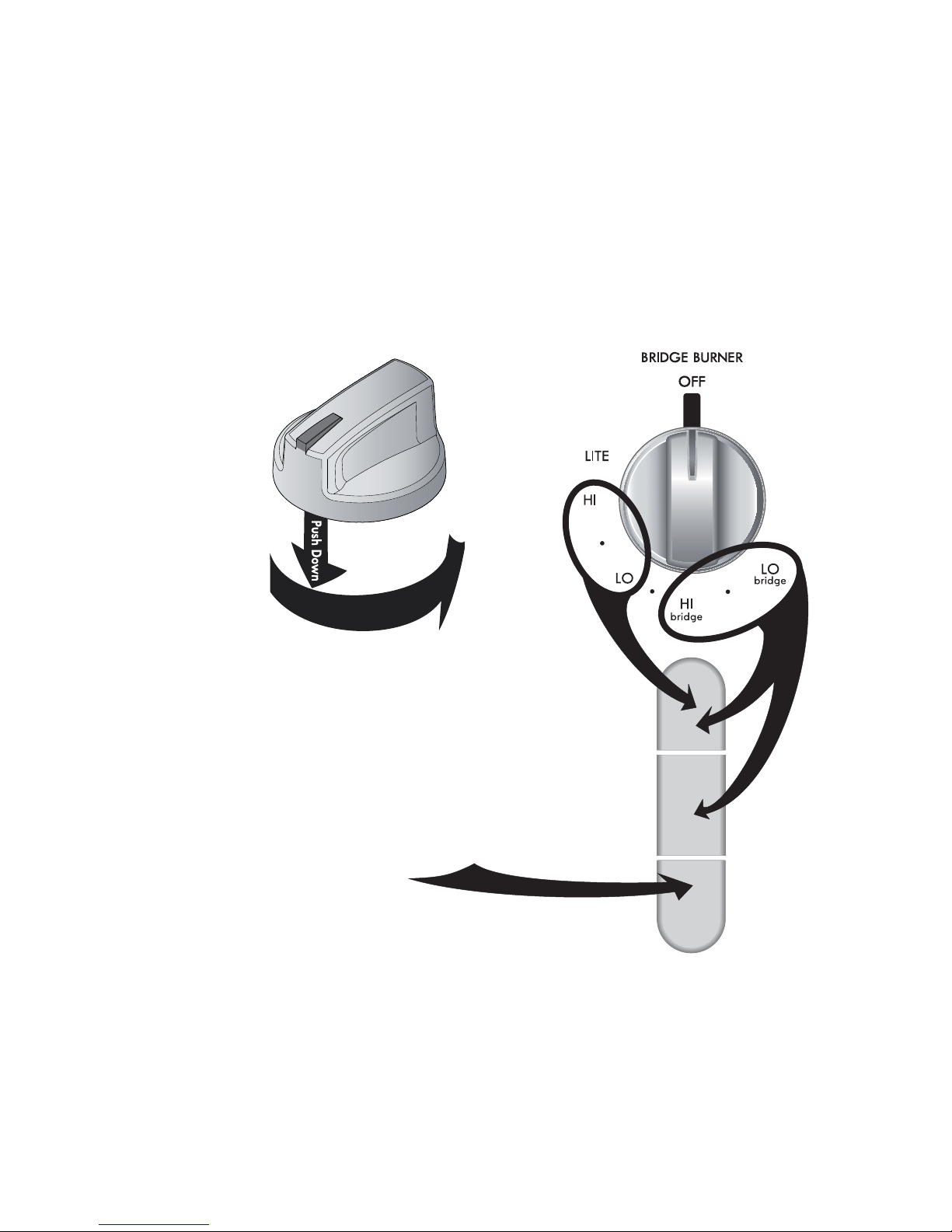
Setting the Bridge Burner
The Bridge Burner should be used with rectangular shaped
cookware. Cookware like a cast-iron Griddle is designed
specifi cally for best results with the Bridge Burner.
The Bridge Burner feature may be used to combine the
cooking power of 2 or if needed 3 gas surface Burners
located along the left-hand side of the cooktop. The left
rear and left center Burners are controlled by the left rear
surface Control Knob. In addition the left front Burner may
be added to the Bridge Burner with the left front gas Control
Knob.
Operating the Bridge Burner
1. Push the left rear surface
control knob in and turn
counterclockwise out of
the OFF position (See
Figure 1).
2. Release the knob and
rotate to the LITE
position.
3. Visually check that the
left rear Burner has lit.
4. Continue to rotate
the gas control knob
counterclockwise to the
“HI bridge” position
(Figure 2).
5. Visually check that both the left rear and left center
Burners are lit.
6. When both burners are lit, continue to turn the control
knob counterclockwise to adjust to the desired fl ame
size for both burners together.
Note: The markings between the “HI bridge” and the “LO
bridge” settings adjust the fl ame size for both burners.
7. Add the left front Burner if needed. Once lit, visually
adjust the fl ame size of the left front burner to match
the fl ame size of the bridge burner.
T
u
r
n
C
o
u
Figure 1
o
n
l
t
c
e
r
e
s
i
w
k
c
Important notes:
DO NOT• cook with any of the surface control knobs in
the LITE position (The electronic ignitor will continue to
spark if the knob is left in the LITE position).
When setting any surface control knob to the LITE •
position, all electronic surface ignitors will spark at the
same time. However, only the surface burner you are
setting will ignite.
If only the left rear surface Burner is needed, adjust the •
settings between the 1st HI and LO.
The left front Burner may be added to the Bridge Burner •
by setting the left front gas Control Knob.
Figure 2 - Bridge Burner
12
Page 13

Setting Surface Controls
Setting the Dual Ring Burner
The Dual Ring Burner has two rings of fl ame that you can
control for two diff erent heat levels, one for small and one
for large cookware.
Large Cookware Operation (Figure 1; Zone A & B)
1. Place a large cooking
utensil centered over
the dual surface Burner
Grate.
2. Push the surface control
knob down and turn
counterclockwise out of
the OFF position.
3. Release the knob and
rotate to the LITE
position (Figures 2 & 3).
4. Visually check that the
burner has lit.
5. When the burner is lit,
continue to turn the
control knob counterclockwise between the HI position
and the MED position to adjust to the desired fl ame
size for both burners together (Figure 1).
T
u
r
n
C
o
u
Figure 2
o
n
l
t
c
e
r
e
s
i
w
k
c
B
A
Figure 1
Simmering Operation (Figure 1; Zone A)
1. Place a small cooking utensil centered over the dual
surface Burner Grate.
2. Push the surface control knob in and turn
counterclockwise out of the OFF position (Fig. 2 & 3).
3. Release the knob and rotate to the LITE position.
4. Visually check that zone A & B of dual burner has lit.
5. Continue to turn the gas control knob counterclockwise
past the MED position; zone B will turn off . Adjust the
simmer fl ame size by turning the control knob between
the MED position to the LO position.
Important notes:
• DO NOT cook with the surface control knob left in the
LITE position. (The electronic ignitor will continue to spark
if the control knob setting remains in the LITE position).
• When setting any surface control knob to the LITE
position, all electronic surface ignitors will spark at the
same time. However, only the surface burner you are
setting will ignite.
• NEVER place or straddle a cooking utensil over two
diff erent surface cooking areas at the same time. This
can cause uneven heating results.
Figure 3
Figure 4
13
Page 14

Oven Control Functions
For satisfactory use of your oven, become familiar with the various features and functions of the oven.
1
2
3
4
7
5
10
6
8
9
11
12
16
Oven Control Keypads
1. Timer - Used to set or cancel Timer.
2. Add 1 Minute - Used to add additional minutes to Timer.
3. Cook Time- Used to enter the length of the cook time
desired.
4. Delay Start - Used with Bake, Conv Bake, Conv Convert
and Flex Clean functions to program a delay start time
or delay start self-cleaning cycle.
5. Slow Cook - Used to select the Slow Cook function.
6. Warm - Used to set the Warm & Hold function.
7. Preheat - Used to pre-condition the oven.
8. Cakes & Breads - Used to select the cakes & breads.
9. Conv Convert - Used to select the Convection Convert
function.
10. Clean - Used to set a 2 to 4 hours Self-Clean cycle.
13 14
17
18
15
11. Conv Bake - Used to select the Convection Bake feature.
12. Bake - Used to enter the normal bake feature.
13. START - Used to start oven functions.
14. Broil - Used to select Broil feature.
15. Conv Roast - Used to select the Convection Roast
function.
16. Oven Light - Used to turn oven light ON and OFF.
17. STOP - Used to cancel any oven function previously
entered except Clock and Timer.
18. Clock Set - Used to set the time of day.
19. Oven Lockout - Used to lock oven functions and door.
0 thru 9 number - Used to enter temperature and times.
19
Minimum & maximum
control settings
All of the features listed below have
minimum and maximum time or
temperature settings that may be
entered into the control. An ENTRY
acceptance beep will sound each
time a control pad is touched (the
Oven Lockout pad is delayed 3
seconds).
An ENTRY ERROR tone (3 short
beeps) will sound if the entry of the
temperature or time is below the
minimum or above the maximum
settings for the feature.
Feature Min. Temp. or time Max. temp. or time
PreHeat 170°F/77°C 550°F/288°C
Bake 170°F/77°C 550°F/288°C
Broil 400°F/205°C 550°F/288°C
Timer 0:01 Min. 11:59 Hr./Min.
Flex Clean 2 hours 4 hours
Conv Bake 170°F/77°C 550°F/288°C
Conv Convert 170°F/77°C 550°F/288°C
Conv Roast 170°F/77°C 550°F/288°C
Slow Cook Lo (225°F/180°C) Hi (225°F/180°C)
Cook Time 0:01 Min. 11:59 Hr./Min.
Delay Time 12 Hr. 1:00 Hr./Min. 12:59 Hr./Min.
Delay Time 24 Hr. 0:00 Hr./Min. 23:59 Hr./Min.
14
Page 15

Getting Started
Setting Clock at Power Up
You will be prompted to enter the time of day in the event
of a power failure or when you fi rst provide electric power
to your appliance.
• When your appliance is fi rst powered up, 12:00 will fl ash
in the display.
• Enter the time of day using the numeric key pads and
press START to set.
If an invalid time of day is entered, the control will triple
beep. Re-enter a valid time of day and press START. If
STOP is pressed your clock will start with the time set for
12:00.
Select the CLOCK
other situations such as day light savings.
key to modify the time of day during
Preheat Temperature Display
Once a cooking feature has been started, the control will
display the actual oven temperature while preheating. Once
the oven reaches the oven set temperature, only the oven set
temperature will be displayed.
The preheat temperature display is available with the
following cooking modes:
• Bake
• Conv Bake
Setting Oven Lockout
The Oven Lockout feature automatically locks the oven door
and prevents the oven from being turned on. It does not
disable the clock, Timer or the interior oven lights.
Setting Timer
The timer provided with the oven control serve as extra
reminders in the kitchen. When the timer reaches less than 1
minute the display will start to count down in seconds. When
the time runs out the active timer will beep, and “End” will be
displayed.
The following time settings apply to the timers:
• Min. time: 1 minute
• Max. time: 11 hours 59 minutes
See example below to set the timer for 5 minutes:
1. Press TIMER
2. Enter 5 minutes
3. Press START
To cancel or end the timer, press the TIMER key again.
NOTE: The timer(s) will not aff ect the cooking process.
To Set Add 1 Minute Feature
The ADD 1 MINUTE pad is used to set the Add 1 Minute
feature. When the pad is pressed, 1 minute is added to the
Timer feature if this feature is already active. If the Timer
feature is not active and the pad is pressed, the Timer
feature will become active and will begin counting down
from 1 minute. For further information on how to set the
Timer feature see Timer instructions above.
See example below to lock the oven.
To lock, press and hold OVEN
To unlock, press and hold OVEN for 3 seconds.
DOOR LOCKED will fl ash in the display until the door has
fi nished locking. Once the door has been locked the door
lock indicator will turn on. DOOR LOCKED will then stay
displayed.
Do not attempt to open the oven door while the door lock
indicator is fl ashing.
for 3 seconds.
15
Page 16

Setting Oven Controls
Preheat
Bake
For best baking performance use the Preheat feature. The
Preheat feature will bring the oven up to the set cooking
temperature. A reminder tone will sound indicating when
the set temperature is reached and to place the food in the
oven. Preheating is not necessary when roasting or cooking
casseroles.
The following temperature settings apply to the preheat
feature:
• Auto-suggest (default) setting: 350°F/177°C
• Min. bake setting: 170°F / 77°C
• Max. bake setting: 550°F / 288°C
Setting preheat
See example below to set a preheat to start immediately at
the default temperature.
1. Press PREHEAT
If needed, use numeric keypads to enter a diff erent oven
temperature.
2. Press START
"PRE" and the actual oven temperature shown in the display
will alternate as the oven heats and reaches set temperature.
When the oven is fi nished preheating, the controls will beep
to remind you to place food in the oven. The preheat feature
will perform like the Bake feature and continue to maintain
the oven set temperature until cancelled.
NOTE
To cancel the function, you may press • STOP at any time
when setting the control or during the cooking process.
To change the set temperature while the oven is already •
heating, follow the same procedure described above.
During the preheating, the convection fan will be activated •
to allow the oven to reach its target temperature faster.
The Bake, Broil and Convection elements will also cycle for
a better heat distribution.
Use the bake feature to cook most food items that require
normal cooking temperatures.
The following temperature settings apply to the bake
feature:
• Auto-suggest (default) setting: 350°F/177°C
• Min. bake setting: 170°F / 77°C
• Max. bake setting: 550°F / 288°C
Setting bake
See example below to set a bake to start immediately at
the default temperature.
1. Press BAKE
If needed, use numeric keypads to enter a diff erent oven
temperature.
2. Press START
Once START is pressed the oven will begin heating. The
oven display shows the temperature rising.
After the oven reaches set temperature a beep will indicate
the oven is ready. The oven will continue to maintain this
temperature until the cooking feature is canceled.
NOTE
To cancel the function, you may press STOP at any time
when setting the control or during the cooking process.
To change the set temperature while the oven is already
heating, follow the same procedure described above.
During the preheating, the convection fan will be activated
to allow the oven to reach its target temperature faster.
The Bake, Broil and Convection elements will also cycle for
a better heat distribution.
For best results
• As much as possible, use only one rack on position 2 or
3 and center the pans. If using two racks, place the oven
racks in position 2 and 4.
• When placing multiple food items in the oven allow 2-4”
(5-10cm) of space between the food items for proper air
circulation.
• Dark or dull pans absorb more heat than shiny bakeware
resulting in dark or overbrowning of foods. It may be
necessary to reduce the oven temperature or cook time
to prevent overbrowning of some foods. Dark pans are
recommended for pies. Shiny pans are recommended for
cakes, cookies and muffi ns.
Pan position for one rack
baking.
16
Pan position for two rack
baking.
Page 17

Setting Oven Controls
Cook Time
Adding a cook duration when baking is benefi cial when a
recipe requires a specifi c temperature and period of time to
cook. Following the recipe cook time helps insure the best
possible results.
Delay Start (with cook time)
Adding a cook duration along with a specifi c start time
gives the same benefi ts as the cook time option in addition
to controlling exactly when the cooking process will begin
and end.
Cook time may be set with the following features:
• Preheat
• Bake
• Conv Bake
• Conv Roast
• Slow Cook
See example below to set the oven for bake, starting
immediately with preheating to the auto-suggest (default)
setting of 350°F (177°C) and then to automatically turn off
after 30 minutes:
1. Press BAKE
2. Press START
3. Press COOK TIME
4. Enter 30 minutes
5. Press START
Once START is pressed the oven will cook and after 30
minutes automatically shut-off .
When the Cook Time fi nishes:
1. "End" and the time of day will show in display. The oven
will shut off automatically.
2. The control will beep 3 times. The control will continue to
beep 3 times every 30 seconds until STOP is pressed.
NOTE
To cancel the function, you may press• STOP at any time
when setting the control or during the cooking process.
The maximum Cook Time setting is 11 hours and 59 •
minutes.
After the Cook Time feature has been activated, the •
display will go back to showing the hour of day. Press the
COOK TIME keypad to display any remaining cook time.
• Dark or dull pans absorb more heat than shiny bakeware
resulting in dark or overbrowning of foods. It may be
necessary to reduce the oven temperature or cook time
to prevent overbrowning of some foods. Dark pans are
recommended for pies. Shiny pans are recommended for
cakes, cookies or muffins.
Delay start may be set with the following features:
• Bake
• Conv Bake
• Conv Roast
• Slow Cook
• Flex Clean
See example below to set the oven with preheating for bake
at 375°F (191°C) for 50 minutes and to automatically start
at 5:30:
1. Press BAKE
2. Enter 375°F
3. Press START
4. Press COOK TIME
5. Enter 50 minutes
6. Press START
7. Press DELAY START
8. Enter 5:30
9. Press START
Once START is pressed, the oven will calculate the start time
at which the oven will begin heating.
The oven will continue to maintain this temperature for the
selected time or until the cooking feature is canceled.
NOTE
When setting the • DELAY START option be sure the correct
time of day is set.
You may press • STOP any time when setting the control or
during the cooking process.
You may also choose to use • DELAY START with no COOK
TIME.
Delay Start may be set using a 24 hour clock. See Setting 12 •
or 24 hour display modes for more information.
FOOD POISONING HAZARD. Do not let food sit for more than one hour before or after cooking. Doing so can result in
food poisoning or sickness. Foods that can easily spoil such as milk, eggs, fi sh, meat or poultry, should be chilled in the
refrigerator fi rst. Even when chilled, they should not stand in the oven for more than 1 hour before cooking begins, and
should be removed promptly when fi nished cooking.
17
Page 18

Setting Oven Controls
Convection Bake
Convection Bake uses a fan to circulate the oven heat evenly
and continuously. The improved heat distribution allows for
even cooking with excellent results. Multiple rack cooking
may slightly increase cook times for some foods, but the
overall result is time saved.
The Conv Bake feature should ONLY be used when your
recipe instructions have been written for use with convection
baking.
If your recipe instructions are for normal baking and
you wish to use convection bake, follow the Convection
Convert option instructions. The convection convert option
will automatically adjust the oven temperature so that
convection baking may provide the best possible results.
Conv Bake may be set with the following options:
• Conv Convert
• Cook Time and/or Delay Start
Benefi ts of convection bake:
• Superior multiple oven rack performance.
• Some foods cook up 25 to 30% faster, saving time and
energy.
• No special pans or bakeware required.
The following temperature settings apply to the conv bake
feature:
• Auto-suggest (default) setting: 350°F / 177°C
• Min. bake setting : 170°F / 77°C
• Max. bake setting: 550°F / 288°C
See the example below to set conv bake, starting
immediately with the default setting of 350°F (177°C):
1. Press CONV BAKE
If needed, use numeric keypads to enter a diff erent oven
temperature.
2. Press START
After the oven reaches set temperature, a beep will indicate
the oven is ready. The oven will continue to maintain this
temperature until the cooking feature is canceled.
NOTE
You may press STOP any time when setting the control or
during the cooking process.
For best results
• When baking with a single rack use rack positions 2 or 3.
When using 2 racks use rack positions 2 & 4. When using
3 racks use rack positions 1, 3 & 4.
• Cookies and biscuits should be baked on pans with no
sides or very low side to allow heated air to circulate
around the food.
• Food baked on pans with a dark fi nish will cook faster.
• When placing multiple food items in the oven allow 2-4”
(5-10cm) of space between the food items for proper air
circulation.
Pan position for one rack baking.
Convection air fl ow
Pan position for two rack baking.
18
Page 19

Setting Oven Controls
Convection Convert
The conv convert option allows you to convert any normal
baking recipe using the convection bake feature. The control
uses the normal recipe settings and adjusts to a lower
temperature for convection baking. Conv convert must be
used with Conv Bake feature.
Benefi ts of conv bake using conv convert option:
• Superior multiple oven rack performance.
• Some foods cook up 25 to 30% faster, saving time and
energy.
• No special pans or bakeware required.
For best results
• Place food items using the recommended rack positions.
When baking with a single rack use rack positions 2 or 3.
When using 2 racks use rack positions 2 & 4. When using
3 racks use rack positions 1, 3 & 4.
• Cookies and biscuits should be baked on pans with no
sides or very low side to allow heated air to circulate
around the food.
• Food baked on pans with a dark fi nish will cook faster.
• When placing multiple food items in the oven allow 2-4”
(5-10cm) of space between the food items for proper air
circulation.
See the example below to set conv bake, starting
immediately with the auto-suggest (default) setting of 350°F
(177°C) and adding the conv convert option.
1. Press CONV BAKE
If needed, use numeric keypads to enter a diff erent oven
temperature.
2. Press CONV CONVERT
3. Press START
After the oven reaches the converted set temperature, a
beep will indicate the oven is ready.
The added conv convert option will automatically lower the
set temperature you set from the bake recipe to an adjusted
conv bake temperature.
When conv convert is used with cook time “CF” (Check
Food) will be displayed when the cook time is 75%
complete. The control will also beep at regular intervals until
baking has fi nished. For the Check Food function to operate,
the cook time must be entered before the Conv Convert pad
is pressed.
NOTE
You may press STOP any time when setting the control or
during the cooking process.
19
Page 20

Setting Oven Controls
j
Convection Roast
Convection roast combines a cook cycle with the convection
fan and element to rapidly roast meats and poultry. Heated
air circulates around the meat from all sides, sealing in
uices and fl avors. Meats cooked with this feature are crispy
brown on the outside while staying moist on the inside. In
addition, there is no need to reduce the oven temperature
when using convection roast.
Convection roast may be set with the following options:
• Cook time or cook time with delay start
The following temperature settings apply to convection
roast:
• Factory auto-start default: 350°F/177°C
• Minimum: 170°F / 77°C
• Maximum: 550°F / 288°C
Benefi ts of convection roast:
• Superior multiple oven rack performance.
• Some foods cook up 25 to 30% faster, saving time and
energy.
• No special pans or bakeware required.
For best results
• Preheating is not necessary for most meats and poultry.
• Be sure to carefully follow your recipe’s temperature and
time recommendations or refer to the convection roast
chart for additional information.
• Do not cover foods when dry roasting - this will prevent
the meat from browning properly.
• Since Conv Roast cooks food faster, reduce the cook time
by 25% from the recommended cook time of your recipe
(check the food at this time). If necessary, increase cook
time until the desired doneness is obtained.
See example below to set convection roast to start
immediately with the auto-suggest (default) setting:
1. Press CONV ROAST
If needed, use numeric keypads to enter a diff erent oven
temperature.
2. Press START
Once START is pressed the oven will begin heating.
NOTE
You may press STOP any time when setting the control or
during the cooking process.
Roasting rack instructions
The broil pan, its insert and the roasting rack are available
via the mail order card. When preparing meats for
convection roasting, you may use the broiler pan, insert and
the roasting rack supplied with your appliance. The broiler
pan will catch grease spills and the insert will help prevent
grease splatters. The roasting rack fi ts on top of the insert
allowing the heated air to circulate under the food for even
cooking and helps to increase browning on the underside.
1. Place oven rack on bottom or next to the bottom oven
rack position.
2. Place the insert on the broiler pan.
3. Make sure the roasting rack is securely seated on top of
the insert. Do not use the broiler pan without the insert.
Do not cover the insert with aluminum foil.
4. Position food (fat side up) on the roasting rack. -Fig. 1-
5. Place prepared food on oven rack in the oven.
Roasting rack
Insert
Broil pan
Meat Weight Oven temp Internal temp Minute per lb.
Beef
Poultry
Pork
* For beef: med rare 145°F, med 160°F, well done 170°F
** Stuff ed turkey requires additional roasting time. Shield legs and breast with foil to prevent overbrowning and drying of the skin.
Standing rib roast 4 to 6 lbs. 350°F * 25-30
Rib eye roast 4 to 6 lbs. 350°F * 25-30
Tenderloin roast 2 to 3 lbs. 400°F * 15-25
Turkey, whole** 12 to 16 lbs. 325°F 180°F 8-10
Turkey, whole** 16 to 20 lbs. 325°F 180°F 10-15
Turkey, whole** 20 to 24 lbs. 325°F 180°F 12-16
Chicken 3 to 4 lbs. 350°F - 375°F 180°F 12-16
Ham roast, fresh 4 to 6 lbs. 325°F 160°F 30-40
Shoulder blade roast 4 to 6 lbs. 325°F 160°F 20-30
Loin 3 to 4 lbs. 325°F 160°F 20-25
Pre-cooked ham 5 to 7 lbs. 325°F 160°F 30-40
20
Page 21

Setting Oven Controls
4
3
2
1
Broil
Use the broil feature to cook meats that require direct
exposure to radiant heat for optimum browning results.
The following temperature settings apply to the broil
feature:
• Auto-suggest (default) setting: 550°F / 288°C
• Min. broil setting: 400°F / 204°C
• Max. broil setting: 550°F / 288°C
Setting Broil
See example below to set broil starting immediately with the
auto-suggest (default) setting:
1. Place the broiler insert on the broiler pan, then
place the meat on the insert. Remember to follow all
warnings and cautions.
2. Arrange the interior oven rack to rack position
recommendations. Be sure to place the prepared food
and pan directly under broil element. Leave the oven
door open at the broil stop position when broiling.
3. Press BROIL
If needed, use numeric keypads to enter a diff erent oven
temperature.
4. Press START
NOTE
You may press STOP any time
when setting the control or
during the cooking process.
Broil Stop Position
For best results
• Use the recommended pans and oven rack positions for
the type of meat being prepared.
• For optimum browning results, allow the oven to preheat
5-6 minutes before placing the food in the oven.
• Do not use the broiler pan without the insert.
• Do not cover the broil pan/insert with aluminum foil; the
exposed grease could ignite.
• To prevent food from contacting the broil element and to
prevent grease splattering, do not use the roasting rack
when broiling.
Should an oven fi re occur, close the oven door. If the fi re
continues, throw baking soda on the fi re or use a fi re
extinguisher. Do not put water or fl our on the fi re. Flour may
be explosive and water can cause a grease fi re to spread
and cause personal injury.
The broil pan and its insert are available via the mail order
card. The broil pan insert contains slots that allows grease
from the meat to drain into the broil pan. Place prepared
meat on broil pan insert and then place onto broiler pan as
shown below.
Insert
Be aware that the suggested broil settings table are
recommendations only. Increase or decrease broiling times,
or move to a diff erent rack position to suit for doneness. If
the food you are broiling is not listed in the table, follow the
instructions provided in your cookbook and watch the item
closely.
Food Rack position Temp Cook time in minutes Doneness
Steak 1” thick 3rd or 4th 550°F 6 4 Rare
3rd or 4th 550°F 7 5 Medium
3rd or 4th 550°F 8 7 Well
Pork chops 3/4” thick 3rd or 4th 550°F 8 6 Well
Chicken-bone in 3rd 450°F 20 10 Well
Chicken-boneless 3rd or 4th 450°F 8 6 Well
Fish 3rd 500°F 13 0 Well
Shrimp 3rd 550°F 5 0 Well
Hamburger 1” thick 3rd or 4th 550°F 9 7 Medium
3rd or 4th 550°F 10 8 Well
Broil pan
1st side 2nd side
Rack positions
21
Page 22

Setting Oven Controls
Cakes Breads
Warm & Hold
TM
The Cakes Breads functions are designed to give optimum
baking performance for Cakes or Breads. These functions
work well for baking cakes, brownies, pies (fresh or frozen),
baked custards, cheesecakes, breads, rolls, biscuits, muffi ns
and cornbread.
The Cakes function provides a preheat with a gentle cycling
of heat giving cakes more volume and allowing delicate
foods to cook more evenly.
The Breads function adds a special preheat feature to the
bake cycle that thoroughly heats the oven from top to
bottom to give more evenly browned foods.
See the example below to set Cakes or Breads.
1. Arrange oven racks when cool. If needed preheat oven
as desired and place food in oven.
2. For Cakes, press the CAKES BREADS keypad until
CAKES appears in the oven display.
For Breads, press the CAKES BREADS keypad until
BREADS appears in the oven display.
If needed, use numeric keypads to enter a diff erent oven
temperature.
3. Press START.
The Warm & Hold feature will keep oven baked foods warm
for serving up to 3 hours after cooking has fi nished. After 3
hours the Warm & Hold feature will shut-off automatically.
The Warm & Hold should only be used with foods that are
already at serving temperature. The Warm & Hold feature
will maintain an oven temperature of 170°F (77°C).
The Warm & Hold feature may be used without any other
cooking operations or may be used after cooking has
fi nished using Cook Time or Delay Start.
See example below to set Warm & Hold for the oven to
start immediately.
1. Press WARM & HOLD
2. Press START
See example below to set Warm & Hold to start after a
Cook Time or Delay Start.
1. Press BAKE or any other cooking function.
If needed, enter a diff erent temperature.
2. Press START.
NOTE
You may press STOP any time when setting the control or
during the cooking process.
For best results
• Dark or dull pans absorb more heat than shiny bakeware
resulting in dark or overbrowning of foods. It may be
necessary to reduce the oven temperature or cook time
to prevent overbrowning of some foods. Dark pans are
recommended for pies. Shiny pans are recommended for
cakes, cookies or muffins.
• Breads will have better results baking on a single oven
rack.
• When baking layer cakes or cookies using 2 oven racks,
place cookware on rack in position 2 and 4. For best
results when baking cakes or cookies using a single oven
rack, place rack in position 2 or 3.
3. Press BAKE TIME.
4. Enter time.
5. Press START.
If needed, set a DELAY START feature.
6. Press WARM & HOLD.
7. Press START
NOTE
You may press STOP any time when setting the control or
during the cooking process.
FOOD POISONING HAZARD. Do not let food sit for more
than one hour before or after cooking. Doing so can result in
food poisoning or sickness. Foods that can easily spoil such
as milk, eggs, fi sh, meat or poultry, should be chilled in the
refrigerator fi rst. Even when chilled, they should not stand in
the oven for more than 1 hour before cooking begins, and
should be removed promptly when fi nished cooking.
22
Page 23

Setting Oven Controls
Slow Cook
Recipe Recall
The Slow Cook feature may be used to cook foods more
slowly at lower oven temperatures. Slow Cook provides
cooking results much the same way as a slow cooker or
Crock-Pot.
This feature is ideal for roasting beef, pork & poultry. Slow
cooking meats may result in the exterior of meats becoming
dark but not burnt; this is normal.
Slow Cook may be set with the following options:
• Cook Time
• Cook Time and/or Delay Start
For Slow Cook two settings are available, high (Hi) or low
(Lo). The high setting is best for cooking foods from a 4 to
5 hour time period. The low setting is best for cooking foods
from a 8 to 9 hour time period.
See the example below to set a slow cook.
1. Press SLOW COOK to choose the Hi option -Fig. 1-.
2. Press SLOW COOK again to choose the Lo option
-Fig. 2-.
3. Press START
Fig.1 Fig. 2
NOTE
You may press STOP any time when setting the control or
during the cooking process.
For best results
• Completely thaw all frozen foods before cooking.
• Position multiple racks to accommodate size of cooking
utensils when cooking multiple food item.
• Add any cream or cheese sauces during the last hour of
cooking.
• Do not open the oven door often or leave the door open
when checking foods. The more heat that is lost, the
longer the food will need to cook.
• Cover the foods to keep them moist or use a loose or
vented type cover to allow foods to turn crisp or brown.
• Roasts may be left uncovered so browning can occur.
Cook times will vary depending on the weight, fat content,
bone & the shape of the roast.
• Preheating the oven will not be necessary.
• Use the recipe’s recommended food temperature and a
food thermometer to determine when the food is done.
The Recipe Recall feature may be used to record and recall
your favorite recipe settings. This feature may store 1 setting
for each of the basic cooking pads. The keypads that a
recipe may be stored with are Bake, Conv Bake, Conv
Roast, Cakes Breads, Preheat and Slow Cook. This feature
will also store and recall Cook Time or Warm & Hold added
settings.
See example below to store a typical cookie recipe
(example for baking at 375°F for 9 minutes and to shut-off
automatically).
Preheat* the oven to the desired temperature.
1. Press BAKE.
2. Press 3 7 5.
3. Press START.
4. Press COOK TIME.
5. Enter the desired baking time. Press 9.
6 Press and hold START until acceptance tone sounds
(about 3 seconds).
This recipe is now stored with the Bake key pad.
NOTE
Pressing the START pad after entering cooking temperatures
and times will start the oven. If you wish to store the recipes
but not start the oven press STOP after pressing the START
pad.
* The Cook Time you enter does NOT include additional
time required to Preheat the oven. The oven will begin
to count down the cooking time as soon as the feature is
activated.
See example below to recall a previously stored recipe
under BAKE pad.
1. Press BAKE. The stored recipe is recalled.
2. Press START.
NOTE
Once a recipe has been stored with a keypad, the •
recipe information will be recalled when pressing the
corresponding keypad in the future.
If a recalled recipe includes Cook Time, the oven will •
automatically shut-off when the Cook Time is fi nished.
To erase all recipes stored, see section for Restoring •
factory default settings.
23
Page 24

Setting Oven Controls
Sabbath Mode
Setting Sabbath Mode
This appliance provides special settings for use when
observing the Jewish Sabbath/Holidays. This mode will turn
off all audible tones or visual display changes normally
provided by the oven control. BAKE is the only cooking
features available while in the Sabbath mode.
You must fi rst set the BAKE feature and the temperature(s)
needed, the COOK TIME option if needed before setting
the Sabbath mode. Any settings made prior to setting the
Sabbath mode will be visible in the displays.
The Sabbath mode will override the factory preset 12 Hour
Energy Saving mode and the appliance will stay on until
the cooking features are cancelled. If any of the cooking
features are cancelled when the appliance is in the Sabbath
mode, no audible or visual indicators will be available to
verify the cancellation.
If the oven interior lights are needed, be sure to activate
them prior to setting the Sabbath mode. Once the oven light
is turned ON and the Sabbath mode is active, the oven light
will remain on until the Sabbath mode is turned off and the
oven lights are turned off . The oven door will not activate
the oven interior lights when the oven door is opened or
closed.
It is recommended that any oven temperature modifi cation
made within an active Sabbath mode be followed with 2
presses of the START key. This will insure the oven remains
ON even if an attempt is made to set the oven temperature
outside of its temperature range. If the oven temperature is
set outside of the temperature range, the oven will default
to the nearest available temperature. Try to set the desired
oven temperature again.
Should a power failure or interruption occur during the
Sabbath/Holidays, the appliance will shut OFF. When
power is restored the appliance will not turn back on
automatically to the original BAKE feature settings. SF
will appear in all the control display panels indicating a
Sabbath mode failure. After a power failure, the food may
be safely removed from the oven while still in the Sabbath
mode.
For further assistance, guidelines for proper usage
and a complete list of models with the Sabbath
feature, please visit the web at http:\\www.
star-k.org.
The example below shows setting the oven to observe the
Sabbath (and Jewish holidays).
1. Press BAKE.
2 Press START
Be sure to make any additional oven setting changes
(Oven Light, Cook Time and/or Delay Start, Warm &
Hold) before going to step 3.
3. To enter Sabbath mode, press and hold simultaneously
both the COOK TIME and DELAY START keys together
for 3 seconds (a beep will sound) and release.
Once properly set in Sabbath mode, SAb will show in the
oven display until the Sabbath mode is cancelled.
NOTE
You may press STOP any time when setting the control or
during the cooking process.
Cancelling Sabbath mode
The example below shows how to cancel the Sabbath mode.
1. Press and hold both the COOK TIME and DELAY
START keys together for 3 seconds (a beep will
sound) and release.
2. All cooking features previously set will automatically
cancel once Sabbath mode has ended.
NOTE
The only keys available once the appliance is set for the
Sabbath mode are BAKE, START, STOP and the numeric
pads.
You may change the oven temperature once baking has
started (Jewish holidays only). Press BAKE, enter the oven
temperature using the numeric keys and press START twice.
Remember that the oven control will no longer beep or
display any further changes once the oven is set in the
Sabbath mode.
24
Page 25

Warmer Drawer
Warm & ReadyTM Drawer
The purpose of the warmer drawer is to keep hot cooked
foods at serving temperatures. Examples are vegetables,
gravies, meats, casseroles, biscuits, rolls and pastries. It is
not recommended to heat cold food in the warmer drawer;
always start with hot food.
The warmer drawer may also be used to warm dinner
plates. All food items placed in the warmer drawer should
be covered with a lid or aluminum foil to maintain quality.
Always use potholders or oven mitts when
removing food from the warmer drawer as cookware and
plates will be hot and you can be burned.
FOOD POISONING HAZARD• . Do not let food sit for
more than one hour before or after cooking. Doing so can
result in food poisoning or sickness. Foods that can easily
spoil such as milk, eggs, fi sh, meat or poultry, should be
chilled in the refrigerator fi rst. Even when chilled, they
should not stand in the oven for more than 1 hour before
cooking begins, and should be removed promptly when
fi nished cooking.
Storage in or on appliance—fl ammable materials should •
not be stored in an oven, warmer drawer, near surface
units. This includes paper, plastic and cloth items, such as
cookbooks, plasticware and towels, as well as fl ammable
liquids. Do not store explosives, such as aerosol cans, on
or near the range.
DO NOT LEAVE CHILDREN ALONE —• Children should
not be left alone or unattended in the area where
appliance is in use. They should never be allowed to sit or
stand on any part of the appliance, including the warmer
drawer.
Arranging warmer drawer rack positions
The keep warmer drawer rack may be used in 2 ways:
• In the upright position (See Fig. 1) to allow low profi le food
items to be placed both under and on top of the rack (for
example, rolls or biscuits on top of the rack and a casserole
dish underneath).
• In the downward position (See Fig. 2) to allow for light
weight food items and empty cookware (for example, rolls
or pastries and dinner plates) on the rack.
Warmer Drawer Controls
The warmer drawer controls are located on the control
panel. Use the warmer drawer control keypads to turn
the warmer drawer ON and OFF and make temperature
adjustments. Three available heat settings are provided from
low to high (See Fig. 4).
Warmer drawer indicator light
The warmer drawer indicator light is located beside the
warmer drawer ON/OFF keypad (See Fig. 3). It glows when
the warmer drawer is turned ON, and remains on until the
warmer drawer is turned OFF.
indicator light
Fig. 3
Always use potholders or oven mitts when
removing food from the warmer drawer as cookware and
plates will be hot and you can be burned.
To set warmer drawer:
1. Arrange the warmer drawer rack (if needed) in warmer
drawer and place the cooked food or dishes in the
warmer drawer. Close warmer drawer.
2. To activate press and hold the warmer drawer ON/OFF
keypad until acceptance tone sounds.
3. To set heat level press Hi or Lo keypad and if needed
toggle using these keypads to adjust to the desired
power level setting. Release keypad when the desired
heat level is displayed by the indicator lights. Fig. 4
shows examples for low, medium and high settings.
4. Once warming is fi nished, press ON/OFF to turn warmer
drawer OFF and carefully remove items.
Fig. 1
Fig. 4
Fig. 2
25
Page 26

Warmer Drawer
Proof Bread
The warmer drawer has a Proof Bread feature that may be
used to prepare bread dough. The recommended length
of time to keep the bread dough in the warmer drawer is
about 45-60 minutes. Be sure however to follow the recipe’s
recommended times.
Warmer Drawer Settings
The recommended warmer drawer food settings are shown
in Fig. 3. The settings provided are meant to be used as a
recommendation only. If a particular food item is not listed,
start with a medium setting. If more crispness is desired,
remove the lid or aluminum foil from the food.
Since the bread dough will nearly double in volume be sure
to place the prepared dough in a large bowl. Arrange the
warmer drawer rack in the downward position (See Fig. 1)
and place the bowl with dough on the warmer drawer rack.
Fig. 1
To set Proof Bread using warmer drawer:
1. Arrange the warmer drawer rack in warmer drawer
(See Fig. 1) and place bread dough in a large bowl on
warmer drawer rack. Close warmer drawer.
2. Press ON/OFF keypad to turn ON warmer drawer.
3. Press Lo keypad once set warmer drawer to Lo power
setting.
4. Press Lo keypad again to activate Proof Bread feature.
The Proof Bread indicator light will glow when the Proof
Bread feature is active (See Fig. 2).
5. When the bread dough is ready, press the ON/OFF
keypad to turn the warmer drawer off and remove bread
dough from warmer drawer.
Most foods may be maintained at serving temperatures
using a medium heat setting. When a combination of foods
are to be kept warm (for example, a meat with 2 vegetables
and rolls) use a high setting.
Warmer drawer recommended food settings
Food Item Setting
Bacon Hi
Hamburger patties Hi
Poultry Hi
Pork chops Hi
Fried foods Hi
Pizza Hi
Gravies medium
Casseroles medium
Eggs medium
Roasts (beef, pork or lamb) medium
Vegetables medium
Biscuits medium
Rolls (hard) medium
Pastries medium
Rolls (soft) Lo
Empty dinner plates Lo
Fig. 3
Important notes:
• Do not use plastic wrap to cover food. Plastic may melt
on the warmer drawer and be very diffi cult to clean up.
Only use utensils and cookware recommended by the
manufacturer for use in the warmer drawer.
• Always start with hot food when using the warmer drawer.
DO NOT heat cold food in the warmer drawer.
• To minimize heat loss, avoid opening warmer drawer
frequently while in use.
• Flex Clean can not be set when the warmer drawer is
active.
• If Proof Bread indicator light turns on when setting the
heat level press Hi keypad to toggle back to the three
warmer drawer settings.
Fig. 2
26
Page 27

User Preferences
°
Setting Clock
See the example below to set the clock to 1:30.
1. Press
2. Enter 1:30 to advance to 1:30.
3. Press START to accept or press STOP to reject.
Setting 12 or 24 Hour Mode
The clock display mode allows you to choose between 12
and 24 hour mode. The factory preset clock display mode is
12 hour.
See the example below to change the default mode to 24
hour.
1. Press and hold
“24Hr dAy” appear in the display.
2. Press CLEAN to switch between the 12 and 24 hour
mode.
3. Press START to accept or press STOP to reject.
Adjusting Oven Temperature
User preference off set
Your appliance has been factory calibrated and tested to
ensure an accurate baking temperature. For the fi rst few uses,
follow your recipe times and temperature recommendations
carefully.
If you feel your oven is too hot or too cool from your baking
experience, the oven temperature may be adjusted to your
liking. The temperature may be increased up to +35°F (+19°C)
or decreased down to -35°F (-19°C) from normal.
See the example below to increase the temperature.
1. Press and hold BAKE for 7 seconds until UPO appear in
the display.
2. Enter the desired temperature change using the number
pads. CLEAN can be pressed to lower the temperature.
3. Press START to accept or press STOP to reject.
Setting Silent Control Operation
The silent control operation allows you to control the audio
for the oven control. You may turn the audio off and later
return to operating with all the normal audible sounds and
alerts.
See the example below when changing the audible settings.
1. Press and hold DELAY START for 7 seconds until BEEP
appear in the display.
2. Press CLEAN to switch between the On and Off mode.
.
for 7 seconds until “12Hr dAy” or
Changing Between F° or C
Your control has the ability to display and set Fahrenheit or
Celsius temperatures. The factory preset temperature display
is Fahrenheit.
See the example below to change the default temperature
display to Celsius.
1. Press and hold BROIL for 7 seconds until F or C appear
in the display.
2. Press CLEAN to switch between the F and C mode.
3. Press START to accept or press STOP to reject.
Setting 12hr Energy Saving Mode
The oven control has a factory preset built-in 12 hour energy
saving feature that will shut off the appliance if the oven
has been heating for more than 11 hours and 59 minutes.
The oven can be programmed to override this feature for
continuous baking.
See the example below to turn off 12 hour energy saving
mode.
1. Press and hold TIMER for 7 seconds until “12Hr OFF” or
“StAy On” appear in the display.
2. Press CLEAN to switch between the “12Hr OFF” or “StAy
On” mode.
3. Press START to accept or press STOP to reject.
Restoring Factory Default Settings
When new, your appliance was set with predetermined oven
control settings. Over time, the user may make changes to
these default settings. The following features or functions
have user options or adjustments that may have been
changed from the factory default settings:
• 12 or 24 hour display mode
• Continuous bake or 12-Hour Energy Savings mode
• Silent or audible control
• Oven temperature display (Fahrenheit or Celsius)
• Oven temperature adjustments
• All stored recipes
Please be aware before restoring to factory default
settings that ALL of the above user settings will be restored,
including any oven temperature off set and any stored recipe
information.
1. Press and hold the 7 numeric keypad until acceptance
tone sounds (about 6 seconds).
2. Press START. The control will reset all user preference
settings back to factory default settings.
3. Press START to accept or press STOP to reject.
27
Page 28

Self-Cleaning Cycle
Before Starting Self-Clean
A self-cleaning oven cleans itself with high temperatures
that are well above those used for normal cooking. The high
cleaning temperature eliminates soils completely or reduces
them to a fi ne powdered ash that you can later easily wipe
away with a damp cloth.
Adhere to the following precautions when running the selfclean cycle:
• Allow the oven to cool before cleaning.
• Wear rubber gloves when cleaning any exterior parts of
the oven manually.
• Do not use oven cleaners or protective coatings in or
around the oven interior.
• Do not clean the oven door gasket. The woven material
of the oven door gasket is essential for a good seal. Care
should be taken not to rub, damage or remove the gasket.
-Fig. 1-
• Do not use any cleaning materials on the door gasket.
Leaving chemical residue can damage the door gasket.
During the self-clean cycle, the outside of the appliance can
become very hot to the touch. DO NOT leave small children
unattended near the appliance.
• DO NOT line the oven walls, oven racks, bottom or any
other part of the appliance with aluminum foil. Doing so
will stop heat distribution, produce poor baking results
and cause permanent damage to the oven interior
(aluminum foil will melt to the interior surface of the
oven).
• DO NOT force the oven door open. This can damage the
automatic door locking system. Use caution when opening
the door after the self-clean cycle is fi nished. The oven
may still be VERY HOT.
• The health of some birds is extremely sensitive to the
fumes given off during the self-cleaning cycle of any
appliance. Move birds to another well-ventilated room.
• Do not force the oven door open. The automatic door
locking system can be damaged.
• Remove all utensils and any aluminum foil from the
oven. These items cannot withstand high cleaning
temperatures.
• This oven comes with lubricated porcelain oven racks,
which can remain in the oven during the self-clean cycle.
Do not clean this vegetable oil lubrication off the racks. It
is important that the sides of the oven racks always have
a light coating of vegetable oil. To maintain optimal rack
performance, re-apply a thin layer of vegetable oil to the
sides of the rack after every self-clean cycle or when the
rack becomes diffi cult to slide.
• Remove any excessive spillovers in the oven cavity
before starting a self-clean cycle. To clean, use hot, soapy
water and a cloth. Large spillovers can cause heavy
smoke or fi re when subjected to high temperatures.
• Clean any soil from the oven frame, the door liner outside
the oven door gasket and the small area at the front
center of the oven bottom with soap and water. These
areas heat suffi ciently to burn soil on.
• Do not allow food spills with a high sugar or acid content
(such as milk, tomatoes, sauerkraut, fruit juices or pie
fi lling) to remain on the porcelain surface, they may leave
a dull spot even after cleaning.
DO NOT
DO Hand
Clean
Frame
DO
Hand
Clean
Door
Fig. 1
Hand Clean
Oven Door
Gasket
What to Expect during Cleaning
While the oven is in operation, the oven heats to
temperatures much higher than those used in normal
cooking. Sounds of metal expansion and contraction are
normal. Odor is also normal as the food soil is being
removed. Smoke may appear through the oven vent.
If heavy spillovers are not wiped up before cleaning, they
may fl ame and cause more smoke and odor than usual.
This is normal and safe and should not cause alarm. If
available, use an exhaust fan during the self-cleaning cycle.
28
Page 29

Self-Cleaning Cycle
Flex Clean Cycle
The CLEAN pad controls the Self-Cleaning feature. When
used with a the Delay Start pad, a delayed Self-Cleaning
cycle may also be programmed. The Flex Clean feature
allows for any Self-Cleaning cycle time from 2 (2:00) to 4
hours (4:00). You may also choose the clean time in 1 minute
increments (for example 2 hours and 50 minutes) by pressing
the corresponding number keypads.
If you are planning to use the oven directly after a self-clean
cycle remember to allow time for the oven to cool down
and the oven door to unlock. This normally takes about one
hour. So a 3 hour self-clean cycle will actually take about 4
hours to complete.
*It is recommend to use a 2 hour self-clean cycle for light soils,
a 3 hour cycle for average soils, and a 4 hour cycle for heavy
soils (to assure satisfactory results).
NOTE: The kitchen area should be well ventilated using an
open window, ventilation fan or exhaust hood during the
Self-Clean cycle. This will help eliminate the normal odors
associated with the Self-Clean cycle.
See example below to start an immediate Self-Cleaning
cycle or to set a Delay Start time of 9:00 o’clock and shutoff automatically (example provided is a default 3 hour
Self-Clean cycle)
1. Be sure the clock is set with the correct time of day, the
oven is EMPTY and the oven door is closed.
2. Press CLEAN.
The control will automatically clean for a 3 hour period
(default self-cleaning cycle time). Note: If a 2 or 4 hour
clean time is desired, press 2 0 0 for 2 hour or press 4 0
0 for a 4 hour clean time. Set the cleaning time based
on the amount of soil: light, medium or heavy (*See
above).
3. Press START.
As soon as the control is set, the motor driven oven door
lock will begin to close automatically. Once the door
has been locked the “DOOR LOCKED” indicator light
will stop fl ashing and remain on.
Note: Allow about 15 seconds for the oven door lock to close.
Note: If the optional delay Self-Clean feature is needed,
fi nish steps 4-6.
4. Press DELAY START.
5. Enter the desired Self-Clean starting time using the
number pads 9 0 0.
6. Press START.
The control will calculate forward from the set start time
to determine when the Self-Cleaning cycle should end.
The Self-Cleaning cycle will turn on automatically at the
set time.
• To avoid possible burns use care when opening the oven
door after the Self-Cleaning cycle. Stand to the side of
the oven when opening the door to allow hot air or steam
to escape.
• DO NOT force the oven door open. This can damage
the automatic door locking system. Use caution and
avoid possible burns when opening the door after the
Self-Cleaning cycle has completed. The oven may still be
VERY HOT.
When the Self-Clean Cycle is Completed
Once the oven has cooled down for approximately 1 HOUR,
and the “DOOR LOCKED” icon is no longer displayed, the
oven door can then be opened.
Stopping or Interrupting a Self-Cleaning Cycle
If it becomes necessary to stop or interrupt a self-cleaning
cycle due to excessive smoke or fi re in the oven:
1. Press STOP.
2. Once the oven has cooled down for approximately 1
HOUR, and the “DOOR LOCKED” icon is no longer
displayed, the oven door can then be opened.
NOTE
A smoke eliminator in the oven vent converts most of the
smoke into a colorless vapor.
IMPORTANT
If a self-clean cycle was started but did not fi nish due to a
power failure, your oven may not be completely cleaned.
After power has been restored and the oven door has
unlocked, set for another self-clean if needed.
29
Page 30

Care & Cleaning
Before cleaning any part of the oven, be sure all controls are turned OFF and the oven is COOL. REMOVE SPILLOVERS AND
HEAVY SOILING AS SOON AS POSSIBLE. REGULAR CLEANINGS NOW WILL REDUCE THE EXTENT AND DIFFICULTY OF
MAJOR CLEANING LATER.
Surface Type Cleaning Recommendation
Painted body parts,
Painted decorative trim
Aluminum, plastic or vinyl trim
Control knobs (some models)
Control panel
Control keypad membrane
Decorative trim (some models)
Porcelain enamel parts and door
liner
Oven interior For oven interior, remove excessive spillovers from oven cavity bottom before starting
For general cleaning, use hot, soapy water and a cloth. For more diffi cult soils and built-
up grease, apply a liquid detergent directly onto the soil. Leave on soil for 30 to 60
minutes. Rinse with a damp cloth and dry. Do not use abrasive cleaners on any of these
materials; they can scratch. To remove control knobs, turn to the OFF position; grasp
fi rmly and pull straight off the shaft. To replace knobs after cleaning, line up the fl at
sides of both the knob and the shaft; then push the knob into place.
Before cleaning the control panel, turn all controls to OFF, active the lockouts (some
models) and if needed remove any control knobs from the panel. Do not use abrasive
cleaners on any of these materials; they can scratch. Clean using hot, soapy water and
a dishcloth. Rinse with a clean water using a dishcloth. Be sure to squeeze excess water
from the cloth before wiping the panel; especially when wiping around the controls.
Excess water in or around the controls may cause damage to the appliance.
Gentle scouring with a soapy scouring pad will remove most spots. Rinse with a
1:1 solution of clear water and ammonia. If necessary, cover diffi cult spots with an
ammonia-soaked paper towel for 30 to 40 minutes. Rinse with clean water and a
damp cloth, and then scrub with a soap-fi lled scouring pad. Rinse and wipe dry with
a clean cloth. Remove all cleaners or the porcelain may become damaged during
future heating. Do no allow food spills with high sugar or acid content (milk, tomatoes,
sauerkraut, fruit juices or pie fi lling) to remain on the surface; they may cause a dull
spot even after cleaning.
Flex Clean. Clean any soils from oven frame and door liner outside the oven door
gasket. For very important cleaning precautions, be sure to read all the instructions in
the Flex Clean section.
Porcelain coated oven racks This oven comes with lubricated porcelain oven racks, which can remain in the oven
during the self-clean cycle. Do not clean this vegetable oil lubrication off the racks. It
is important that the sides of the oven racks always have a light coating of vegetable
oil. To maintain optimal rack performance, re-apply a thin layer of vegetable oil to the
sides of the rack after every self-clean cycle or when the rack becomes diffi cult to slide.
Oven door Use soap & water to thoroughly clean the top, sides and front of the oven door. Rinse
well. You may use a glass cleaner on the outside glass of the oven door. Do not immerse
the door in water. Do not spray or allow water or the glass cleaner to enter the door
vents. Do not use oven cleaners, cleaning powders or any harsh abrasive cleaning
materials on the outside of the oven door.
Do not clean the oven door gasket. The oven door gasket is made of a woven material,
on Self-Cleaning models, which is essential for a good seal. Care should be taken not to
rub, damage or remove this gasket.
Cooktop surface, surface burners
and burner grates.
Stainless Steel (some models) Only use cleaners and polishes that are specifi cally manufactured for cleaning stainless
Do not use spray oven cleaners on the cooktop. See “Cooktop cleaning” and “Cleaning
the cooktop and burner grates” later in the Care & Cleaning section.
steel. Always wipe in direction of metal grain to avoid damaging. Do not use cleaners
with high concentrations of chlorides or chlorine. Do not use harsh scrubbing cleaners.
Polish with a lint-free cloth. Always be sure to wipe excess cleaner/polish off from the
metal surface as bluish stains may occur during future oven heating that cannot be
removed. Clean heavier soils with hot, soapy water and a dishcloth. Rinse and dry using
clean water and a cloth.
30
Page 31

Care & Cleaning
Cleaning the Cooktop and Surface Burners
To avoid possible burns DO NOT attempt
any of the cooktop cleaning instructions provided before
turning OFF all of the surface burners and allow them to
completely cool.
Slots
Ignition port
Any additions, changes or conversions
required in order for this appliance to satisfactorily meet the
application needs must be made by an authorized qualifi ed
agency.
Routinely clean the cooktop. Wipe with a clean, damp cloth
and wipe dry to avoid scratches.
Keeping the surface burner head ports and slots clean will
prevent improper ignition and an uneven fl ame. See the
following sections for more instructions.
Cleaning recessed and contoured areas of cooktop
If a spill occurs on or in the recessed or contoured areas,
blot up spill with an absorbent cloth. Rinse with a clean,
damp cloth and wipe dry.
Cleaning surface burner grates
• Clean only after the grates are completely cool.
• Use nonabrasive plastic scrubbing pad and mild abrasive
cleanser or clean in the dishwasher.
• Food soils containing acids may aff ect the fi nish. Clean
immediately after the grates are cool.
• Thoroughly dry grates immediately following cleaning.
Cleaning burner caps
• Remove caps from burner heads after they have cooled.
• Clean heavy soils with a plastic scrubbing pad and
absorbent cloth.
• Thoroughly dry burner caps immediately following
cleaning including the bottom and inside of cap.
• Do not use abrasive cleaners. They can scratch porcelain.
• Do not clean burner caps in the dishwasher.
• Do not operate surface burners without burner caps
properly in place. Read important notes.
Orifi ce port
Figure 1- Cooktop regular burner head
Cleaning surface burner heads
For proper gas fl ow it may be necessary to clean the
burner head and slots. To clean, fi rst use a clean DAMP
cloth to soak up any spills. Remove any food from between
the burner slots using a small nonabrasive brush like a
toothbrush and afterwards wipe up using a damp cloth. For
stubborn soils located in the slots, use a small-gauge wire or
needle to clean.
Any spill on or around the electrode must be carefully
cleaned. Take care not to hit the electrode with any thing
hard or it could be damaged.
To clean the burner head ignition ports
Each burner head has a small ignition port located as
shown. Should you experience ignition problems it may be
that this port hole is partially blocked with soil. With the
burner head in place, use a small wire gauge needle or the
end of a paper clip to clear the ignition port (See to Fig.
1; round style shown - oval or Dual Ring burner on some
models not shown).
Important notes:
• The surface burner heads are secured to the cooktop and
must be cleaned in place on the cooktop.
• Always keep the surface burner caps in place whenever
a surface burner is in use.
• When replacing the burner caps, be sure the burner caps
are seated fi rmly on top of the burner heads.
• For proper fl ow of gas and ignition of burners DO NOT
allow spills, food, cleaning agents or any other material
to enter the gas orifi ce port opening.
31
Page 32

Care & Cleaning
g
Removing and Replacing the Oven Door
The oven door is heavy. Be careful when
removing and lifting the door. Do not lift the oven door by
the handle.
IMPORTANT
break. Read the following recommendations:
• Do not close the oven door until all the interior oven racks
are fully inserted and retracted to the back of the oven.
• Do not hit the glass with pots, pans, or any other object.
The oven door glass may break or even break at a later
time unexpectedly.
• Scratching, hitting, jarring or stressing the oven door glass
may weaken its structure causing an increased risk of
breakage at a later time.
• You may use a glass cleaner on the outside of the oven
door glass. Do not spray or allow water or the cleaner to
enter or drip down into the oven door vents. Spray cleaner
on cloth fi rst and then wipe the oven door clean.
• Do not use strong oven cleaners, powders or any harsh
abrasive cleaning materials on the outside of the oven
door or glass.
• Never clean the oven door gasket. The oven door gasket
should always clean during the Self-clean cycle.
Most oven doors contain glass that can
Door Hinge
locations
with oven door
fully open
Figure 1
Figure 2
To Remove Oven Door:
1. Open oven door completely (horizontal with fl oor - See
Figure 1).
2. Pull the door hinge locks on both left and right door
hinges down from the oven frame completely towards
the oven door (See Figure 2). A tool such as a small fl at-
blade screwdriver may be required.
3. Firmly grasp both sides of oven door along the door sides
(Do not use the oven door handle - See Figure 3).
4. Close the door to the broil stop position (the oven door
will stop into this position just before fully closing).
5. With the oven door in the broil stop position, lift the
oven door hinge arms over the roller pins located on
each side of the oven frame (See Figure 4).
To Replace Oven Door:
1. Firmly grasp both sides of oven door along the door sides
(Do not use the oven door handle - See Figure 3).
2. Holding the oven door at the same angle as the removal
position, seat the hook of the hinge arm onto the roller
pins located on each side of the oven door frame (See
Fig. 4). Also, seat the notch of the hinge arm onto the
bottom of the slot at the same time you seat the hook.
The hook and notch of the hinge arms must be fully
seated onto the roller pins and bottom of the slot.
3. Fully open the oven door (horizontal with fl oor - See
Figure 1).
4. Push the door hinge locks up towards and into the oven
frame on both left and right oven door hinges (See
Figure 2) to the locked position.
5. Close the oven door.
Around
Oven door
Hinge
Figure 3
Roller pin
Hinge arm hook
Hinge arm notch
Slot bottom
32
ure 4
Fi
Page 33

Care & Cleaning
Removing and Replacing the Drawer
Replacing the Halogen Oven Light
To Remove the Drawer:
1. Open the drawer to the fully opened position.
2. Locate glide lever on each side of drawer, pull up on the
left glide lever and push down on the right glide lever (See
Figure 1).
3. Pull the drawer away from the range.
To Replace the Drawer:
1. Pull the plastic slider to the front of the glide slots on
each side of the drawer cavity (See Figure 2).
2. Align the glide on each side of the drawer with the
drawer cavity glide slot.
3. Push the drawer into the drawer cavity until glide levers
“click” (approximately 2”). If you do not hear the glide
levers “click” or the drawer does not feel seated
remove the drawer and repeat steps 1 thru 3.
Left Glide
Lever
Pull up lever
with fi nger
The oven lights will automatically turn ON when the oven
door is opened. The oven lights may also be manually
operated by pressing the
The oven light bulb is covered with a glass shield. The
glass shield can be removed to be cleaned manually or to
change oven light. THIS GLASS SHIELD MUST BE IN PLACE
WHENEVER THE OVEN IS IN USE.
pad.
To replace the light bulb:
BE SURE THE OVEN IS COOL.
1. Turn the power off at the main source.
2. Wear a leather-faced glove for protection against
possible broken glass.
3. To remove the glass shield, lift up on side and use force
to pull shield out.
4. Replace halogen light appliance bulb taking care not
to touch the bulb with your bare fi ngers. Touching bulb
with your skin can leave a fi lm on the bulb that causes
it to burn out quickly.
5. Replace glass shield in opposite order and manner of
removal.
Push down
lever with
fi nger
Lever
Figure 2
Figure 1
Lift up and pull out.
Right Glide
Halogen
Light Bulb
33
Page 34

Before You Call
(Solutions to Common Problems)
Oven Baking
For best cooking results, heat the oven before baking cookies, breads, cakes, pies or pastries, etc. There is no need to
preheat the oven for roasting meat or baking casseroles.
The cooking times and temperatures needed to bake a product may vary slightly from your previously owned appliance.
Baking Problems and Solutions Chart
BAKING
PROBLEMS
Cookies and biscuits
burn on the bottom.
Cakes too dark on top
or bottom.
Cakes not done in the
center.
Cakes not level. • Range not level.
CAUSES CORRECTIONS
• Cookies and biscuits put into the
oven before the preheating time
is completed.
• Oven rack overcrowded.
• Dark pan absorbs heat too fast.
• Cakes put into the oven before
preheating time is completed.
• Rack position too high or low.
• Oven too hot.
• Oven too hot.
• Incorrect pan size.
• Pan not centered in oven.
• Pan too close to oven wall or
rack overcrowded.
• Pan warped.
• Allow oven to preheat to the selected temperature
before placing food in oven.
• Choose pan sizes that will permit 5.1cm to 10.2cm (2”
to 4”) of air space on all sides when placed in the
oven.
• Use a medium-weight aluminum baking sheet.
• Allow oven to preheat to the selected temperature
before placing food in the oven.
• Use proper rack position for baking needs.
• Set oven temperature 25°F/12°C lower than
recommended.
• Set oven temperature 25°F/12°C lower than
recommended.
• Use pan size suggested in recipe.
• Use proper rack position and place pan so there is
5.1cm to 10.2cm (2” to 4”) of space on all sides of pan.
• Place a marked glass measuring cup fi lled with water
on the center of the oven rack. If the water level is
uneven, refer to the installation instructions for leveling
the range.
• Be sure to allow 5.1cm to 10.2cm (2” to 4”) of
clearance on all sides of each pan in the oven.
• Do not use pans that are dented or warped.
Foods not done when
cooking time is up.
• Oven too cool.
• Oven overcrowded.
• Oven door opened too
frequently.
• Set oven temperature 25°F/12°C higher than suggested
and bake for the recommended time.
• Be sure to remove all pans from the oven except the
ones to be used for baking.
• Open oven door only after shortest recommended
baking time.
34
Page 35

Before You Call
Before you call for service, review this list. It may save you time and expense. The list includes common occurrences that are
not the result of defective workmanship or materials in this appliance.
(Solutions to Common Problems)
OCCURRENCE POSSIBLE CAUSE/SOLUTION
Oven Control Beeps and
Displays any F code error
(example F11).
“d-O” is displayed. The door was left open and controls set for self-cleaning cycle. Close the door and push
Faulty installation.
Range not leveled.
Bad cooking results.
Surface burners do not light. Surface control knob has not been completely turned to LITE. Push in and turn the
Surface burner fl ame burns half
way around.
Surface burner fl ame is orange. Dust particles in main line. Allow the burner to operate a few minutes until fl ame turns
Electronic control has detected a fault condition. Press STOP to clear the display and
stop the beeping. Reprogram the oven. If a fault reoccurs, record the fault number. Press
STOP and call Sears or another qualifi ed servicer.
STOP pad.
Place oven rack in center of oven.
Place a level or a marked glass measuring cup fi lled with water on the center of the
oven rack.
If the water level is uneven, adjust the leveling legs of the unit (refer to the installation
instructions for leveling the range).
If the level is still uneven, contact an installing agent to adjust the cabinet cutout
fl ooring.
Kitchen cabinet misalignment may make oven appear to be not level. Be sure cabinets
are square and level. Contact cabinet maker to correct problem.
surface control knob to LITE until burner ignites and then turn the surface control knob
to the desired fl ame size.
Burner ports are clogged. Clean burners. See “Cleaning the Burner Grates, Burner Caps
and Burner Heads” under General Cleaning.
Range power is disconnected from outlet. Be sure cord is securely plugged into the
outlet.
Electrical power outage.
Be sure the gas supply to the range is turned “ON”.
Burner ports or slots are clogged. With the burner off , use a small-gauge wire or needle
to clean ports or slots.
Moisture is present after cleaning. Lightly fan the fl ame and allow the burner to operate
until fl ame is full. Dry the burners thoroughly following instructions under General Cleaning.
blue.
Salt air in coastal areas. A slightly orange fl ame is unavoidable.
Fan noise during cooking
operation.
Entire oven does not operate. When the oven is fi rst plugged in, or when the power supply to the oven has been
A cooling fan may automatically turn on and off to cool internal parts. This is normal,
and the fan may continue to run even after oven is turned off .
interrupted, the display will fl ash. The oven cannot be programmed until the clock is set.
Be sure electrical cord is securely connected into the electrical junction box.
Cord/plug is not installed and/or connected. Cord is not supplied with oven. Contact
Sears or another qualifi ed servicer.
Service wiring not complete. Contact Sears or another qualifi ed servicer.
Power outage. Check house lights to be sure. Call your local electric company.
Short in cord/plug. Replace cord/plug.
Controls are not set properly. See instructions under Setting Oven Controls to set the
controls.
House fuse has blown or circuit breaker has tripped immediately following installation.
House fuse may not be fully engaged. Check fuse and screw or engage circuit breaker
securely.
House fuse has blown or circuit breaker has tripped after the oven has been installed
and previously operating. Call Sears or another qualifi ed servicer.
35
Page 36

Before You Call
(Solutions to Common Problems)
OCCURRENCE POSSIBLE CAUSE/SOLUTION
Oven smokes excessively
during broiling.
Poor baking results.
Oven too cool or too hot.
Self-cleaning cycle does not
work.
Soil not completely removed
after self-cleaning cycle is
completed.
Flames inside oven or smoke
from vent.
Make sure the oven door is closed. Door should be closed during broiling.
Meat too close to the broiler unit. Reposition the rack to provide more clearance
between the meat and the broiler. Preheat broil burner for quick searing operation.
Meat not properly prepared. Remove excess fat from meat. Slash remaining fatty edges
to prevent curling, but do not cut into the lean.
Grid on broiler pan wrong side-up. Grease does not drain into broiler pan. Always
place the grid on the broiler pan with the ribs up and the slots down to allow grease to
drip into the pan.
Broiler pan used without grid or grid cover with foil. DO NOT use the broiler pan
without the grid or cover the grid with foil.
Oven needs to be cleaned. Grease has built up on oven surfaces. Regular cleaning
is necessary when broiling frequently. Old grease or food spatters cause excessive
smoking.
Many factors aff ect baking results. See Oven Baking for hints, causes and corrections.
See Adjusting Oven Temperature.
Make sure the oven door is closed.
Controls not set properly. Follow Self-Cleaning instructions in this Use & Care Guide.
Self-cleaning cycle was interrupted. Stop time must be set 2-4 hours past the start time.
Follow steps under “Stopping or Interrupting a Self-Cleaning Cycle” in this Use & Care
Guide.
Before starting the Self-Cleaning cycle, hand clean any soil from the oven frame, the door
liner outside the oven door gasket, and the small area at the front center of the oven. These
surfaces are not in the self-cleaning area. Clean with soap and water. Burned-on residue
can be cleaned off with a stiff nylon brush and water or nylon scrubber. DO NOT hand
clean the oven door gasket or it will be permanently damaged.
Excessive spillovers in oven. Set the self-clean cycle for longer cleaning time.
Excessive spillovers in oven. This is normal, especially for high oven temperatures, pie
spillovers or for large amounts of grease on bottom of oven. Wipe up excessive pie
fi lling spillovers.
36
Page 37

Master Protection Agreements
Congratulations on making a smart purchase.
Your new
Kenmore
®
product is designed and manufactured for years of
dependable operation. But like all products, it may require
preventive maintenance or repair from time to time. That’s when
having a Master Protection Agreement can save you money
and aggravation.
The Master Protection Agreement also helps extend the life of
your new product. Here’s what the Agreement* includes:
; Parts and labor needed to help keep products operating
properly under normal use, not just defects. Our coverage
goes well beyond the product warranty. No deductibles,
no functional failure excluded from coverage – real
protection.
; Expert service by a force of more than 10,000 authorized
Sears service technicians, which means someone you
can trust will be working on your product.
; Unlimited service calls and nationwide service, as
often as you want us, whenever you want us.
; «No-lemon» guarantee – replacement of your covered
product if four or more product failures occur within twelve
months.
; Product replacement if your covered product can’t be
fixed.
; Annual Preventive Maintenance Check at your request –
no extra charge.
; Fast help by phone – we call it Rapid Resolution –
phone support from a Sears representative on all products.
Think of us as a «talking owner’s manual».
; Power surge protection against electrical damage due to
power fluctuations.
; $250 Food Loss Protection annually for any food
spoilage that is the result of mechanical failure of any
covered refrigerator or freezer.
; Rental reimbursement if repair of your covered product
takes longer than promised.
; 10% discount off the regular price of any non-covered
repair service and related installed parts.
Once you purchase the Agreement, a simple phone call is all
that it takes for you to schedule service. You can call anytime
day or night, or schedule a service appointment online.
The Master Protection Agreement is a risk free purchase. If you
cancel for any reason during the product warranty period, we
will provide a full refund. Or, a prorated refund anytime after the
product warranty period expires. Purchase your Master
Protection Agreement today!
Some limitations and exclusions apply. For prices and
additional information in the U.S.A. call 1-800-827-6655.
* Coverage in Canada varies on some items. For full details
call Sears Canada at 1-800-361-6665.
Sears Installation Service
For Sears professional installation
of home appliances, garage
door openers, water heaters, and other major home items, in
the U.S.A. or Canada call 1-800-4-MY-HOME
®
.
PROTECTION AGREEMENTS
Contrats de protection principaux
Félicitations! Vous avez fait un bon achat.
Votre nouvel appareil Kenmore® est
conçu et fabriqué dans le but de vous offrir plusieurs années d’utilisation sans
tracas. Cependant, comme tout appareil, il peut nécessiter un entretien
préventif ou des réparations occasionnelles. C’est pourquoi un contrat de
protection principal peut vous permettre d’épargner de l’argent et vous éviter
des problèmes.
Le contrat de protection principal contribue également à prolonger la durée
de vie de votre nouvel appareil. Voici ce que couvre le contrat* :
; Les pièces et la main-d’oeuvre requises pour le fonctionnement
adéquat de l’appareil dans des conditions d’utilisation normales, pas
seulement pour les défauts. Notre couverture vous offre beaucoup plus
que la simple garantie du produit. Aucune franchise, aucune exclusion
de défaillance fonctionnelle, une véritable protection.
; Un service professionnel offert par une équipe de plus de 10 000
techniciens de service Sears autorisés, ce qui signifie que votre
appareil sera confié à une personne de confiance.
; Des appels de service illimités et un service à la grandeur du pays,
à tout moment, aussi souvent que vous le désirez.
; La garantie « anti-citron », vous assurant le remplacement de l’appareil
couvert si quatre défaillances ou plus surviennent à l’intérieur de douze
mois.
; Le remplacement de l’appareil couvert s’il ne peut être réparé.
; Une vérification d’entretien préventive annuelle sur demande et sans
frais.
; Un service d’aide téléphonique rapide, appelé « Résolution rapide »,
qui vous permet de bénéficier du soutien téléphonique d’un représentant
Sears pour tous les produits. Nous sommes votre « guide d’utilisation
parlant ».
; Une protection contre les surtensions pour les dommages électriques
causés par des fluctuations électriques.
; Une couverture annuelle de 250 $ pour la perte d’aliments à la suite
de toute détérioration d’aliments résultant d’une défaillance mécanique
d’un réfrigérateur ou d’un congélateur couvert.
; Le remboursement de la location, si la réparation de l’appareil couvert
prend plus de temps que prévu.
; Un rabais de 10 % sur le prix régulier de tout service de réparation non
couvert et les pièces installées qui en découlent.
Une fois le contrat acheté, un simple appel téléphonique suffit pour obtenir un
service de réparation. Vous pouvez téléphoner à toute heure du jour ou de la
nuit, ou prendre rendez-vous en ligne pour une réparation.
Le contrat de protection principal est un achat sans risque. Si, pour quelque
raison que ce soit, vous annulez le contrat durant la période de garantie du
produit, vous serez remboursé en totalité. En cas d’annulation après la
période de garantie du produit, vous recevrez un remboursement calculé au
prorata. Procurez-vous votre contrat de protection principal dès aujourd’hui!
Certaines restrictions et exclusions s’appliquent. Si vous êtes aux
États-Unis et que vous désirez connaître les prix et obtenir de plus
amples renseignements, téléphonez au 1 800 827-6655.
* Au Canada, la couverture de certains articles peut varier. Pour
connaître tous les détails, communiquez avec Sears Canada au 1 800
361-6665.
Service d’installation Sears
Pour bénéficier du
service d’installation professionnel de Sears
pour
électroménagers, ouvre-portes de garage, chauffe-eau et autres appareils
domestiques importants, aux États-Unis et au Canada, téléphonez au 1 800
4-MY-HOME.
Page 38

Get it fixed, at your home or ours!
Your Home
For troubleshooting, product manuals and expert advice:
www.managemylife.com
For repair – in your home – of all major brand appliances,
lawn and garden equipment, or heating and cooling systems,
no matter who made it, no matter who sold it!
For the replacement parts, accessories and
owner’s manuals that you need to do-it-yourself.
For Sears professional installation of home appliances
and items like garage door openers and water heaters.
1-800-4-MY-HOME
Call anytime, day or night(U.S.A. and Canada)
www.sears.com www.sears.ca
®
(1-800-469-4663)
Our Home
For repair of carry-in items like vacuums, lawn equipment,
and electronics, call anytime for the location of your nearest
Sears Parts & Repair Service Center
1-800-488-1222 (U.S.A.) 1-800-469-4663 (Canada)
www.sears.com www.sears.ca
To purchase a protection agreement on a product serviced by Sears:
1-800-827-6655 (U.S.A.) 1-800-361-6665 (Canada)
Para pedir servicio de reparación
a domicilio, y para ordenar piezas:
1-888-SU-HOGAR
(1-888-784-6427)
www.sears.com
®
Au Canada pour service en français:
1-800-LE-FOYER
(1-800-533-6937)
www.sears.ca
MC
® Registered Trademark / TM Trademark of KCD IP, LLC in the United States, or Sears Brands, LLC in other countries
® Marca Registrada /
MC
Marque de commerce / MD Marque déposée de Sears Brands, LLC
TM
Marca de Fábrica de KCD IP, LLC en Estados Unidos, o Sears Brands, LLC in otros países
 Loading...