

CONSUMER SERVICES TECHNICAL
EDUCATION GROUP PRESENTS
1998 DISHWASHERS
Servicing and Troubleshooting
MODELS
DU800DWG DU801DWG DU805DWG
DU810DWG DP840DWG DU840DWG
KD-10
DU850DWG DU890DWG DU910PFG
DP920PFG DU920PFG GU940SCG
GU960SCG GU980SCG
JOB AID
Part No. 4322430
I

INTRODUCTION
This Job Aid,
specific information for the installation, service and repair of 1998 Whirlpool Dishwashers.
“1998 DISHWASHERS, Servicing and Troubleshooting
cent information on design, features, troubleshooting, service and repair procedures.
“1998 DISHWASHERS, Servicing and Troubleshooting
,” has been compiled to provide the most re-
,” (Part No. 4322430) provides
GOALS AND OBJECTIVES
The goal of this Job Aid is to provide detailed information that will enable the service technician to
properly diagnose malfunctions and repair the 1998 lineup of Dishwashers.
The objectives of the Job Aid are:
The service technician will -
• Understand proper safety precautions.
• Successfully troubleshoot and diagnose malfunction.
• Successfully perform necessary repairs.
• Successfully return the dishwasher to proper operational status.
CORPORATION
WHIRLPOOL CORPORATION ASSUMES NO RESPONSIBILITY
FOR ANY REPAIRS MADE ON OUR PRODUCTS BY ANYONE
OTHER THAN AUTHORIZED SERVICE TECHNICIANS.
© 1998 Whirlpool Corporation, Benton Harbor, MI 49022
II

TABLE OF CONTENTS
INTRODUCTION. . . . . . . . . . . . . . . . . . . . . . . . . . . . . . . . . . . . . . . . . . . II
T ABLE OF CONTENTS. . . . . . . . . . . . . . . . . . . . . . . . . . . . . . . . . . . . III
SAFETY . . . . . . . . . . . . . . . . . . . . . . . . . . . . . . . . . . . . . . . . . . . . . . . . IV
SECTION ONE
DURA WASH MODELS W/ SOIL SETTLER AND TELESCOPING TOWER
Model: DU800DWG, DU801DWG, DU805DWG, DU810DWG, DP840DWG,
DU840DWG, DU850DWG, DU890DWG
Theory of Operation . . . . . . . . . . . . . . . . . . . . . . . . . . . . . . . . . . . . . . . . . . . 1
Component Access . . . . . . . . . . . . . . . . . . . . . . . . . . . . . . . . . . . . . . . . . . . . 3
Solutions to Common Problems . . . . . . . . . . . . . . . . . . . . . . . . . . . . . . . . . 13
Troubleshooting Guide . . . . . . . . . . . . . . . . . . . . . . . . . . . . . . . . . . . . . . . . 15
T echnical Information . . . . . . . . . . . . . . . . . . . . . . . . . . . . . . . . . . . . . . . . . . 16
SECTION TWO
POWER CLEAN FIL TER MODELS W/ TOWER W ATER FEED
Models: DU910PFG, DP920PFG, DU920PFG
Theory of Operation . . . . . . . . . . . . . . . . . . . . . . . . . . . . . . . . . . . . . . . . . . . 27
Component Access . . . . . . . . . . . . . . . . . . . . . . . . . . . . . . . . . . . . . . . . . . . . 28
Troubleshooting Guide . . . . . . . . . . . . . . . . . . . . . . . . . . . . . . . . . . . . . . . . 33
T echnical Information . . . . . . . . . . . . . . . . . . . . . . . . . . . . . . . . . . . . . . . . . . 34
SECTION THREE
POWER CLEAN FILTER MODELS W/ INTERNAL W ATER FEED
Models: GU940SCG, GU960SCG, GU980SCG
Theory of Operation . . . . . . . . . . . . . . . . . . . . . . . . . . . . . . . . . . . . . . . . . . . 43
Component Access . . . . . . . . . . . . . . . . . . . . . . . . . . . . . . . . . . . . . . . . . . . .44
Diagnostics . . . . . . . . . . . . . . . . . . . . . . . . . . . . . . . . . . . . . . . . . . . . . . . . 49
Troubleshooting . . . . . . . . . . . . . . . . . . . . . . . . . . . . . . . . . . . . . . . . . . . . . . 50
T echnical Information . . . . . . . . . . . . . . . . . . . . . . . . . . . . . . . . . . . . . . . . . . 51
SECTION FOUR
Installation Considerations
Custom Door Panel Conversion . . . . . . . . . . . . . . . . . . . . . . . . . . . . . . . . . 55
Floor Mount Kit . . . . . . . . . . . . . . . . . . . . . . . . . . . . . . . . . . . . . . . . . . . . . . . 59
This Service Manual is accompanied by a companion video presentation,
SERVICING AND TROUBLESHOOTING
1998 DISHWSHERS
Part No. 4322329
III

-- NOTES --
IV
DURAWASH MODELS WITH
SOIL SETTLER AND TELESCOPING TOWER
THEORY OF OPERATION
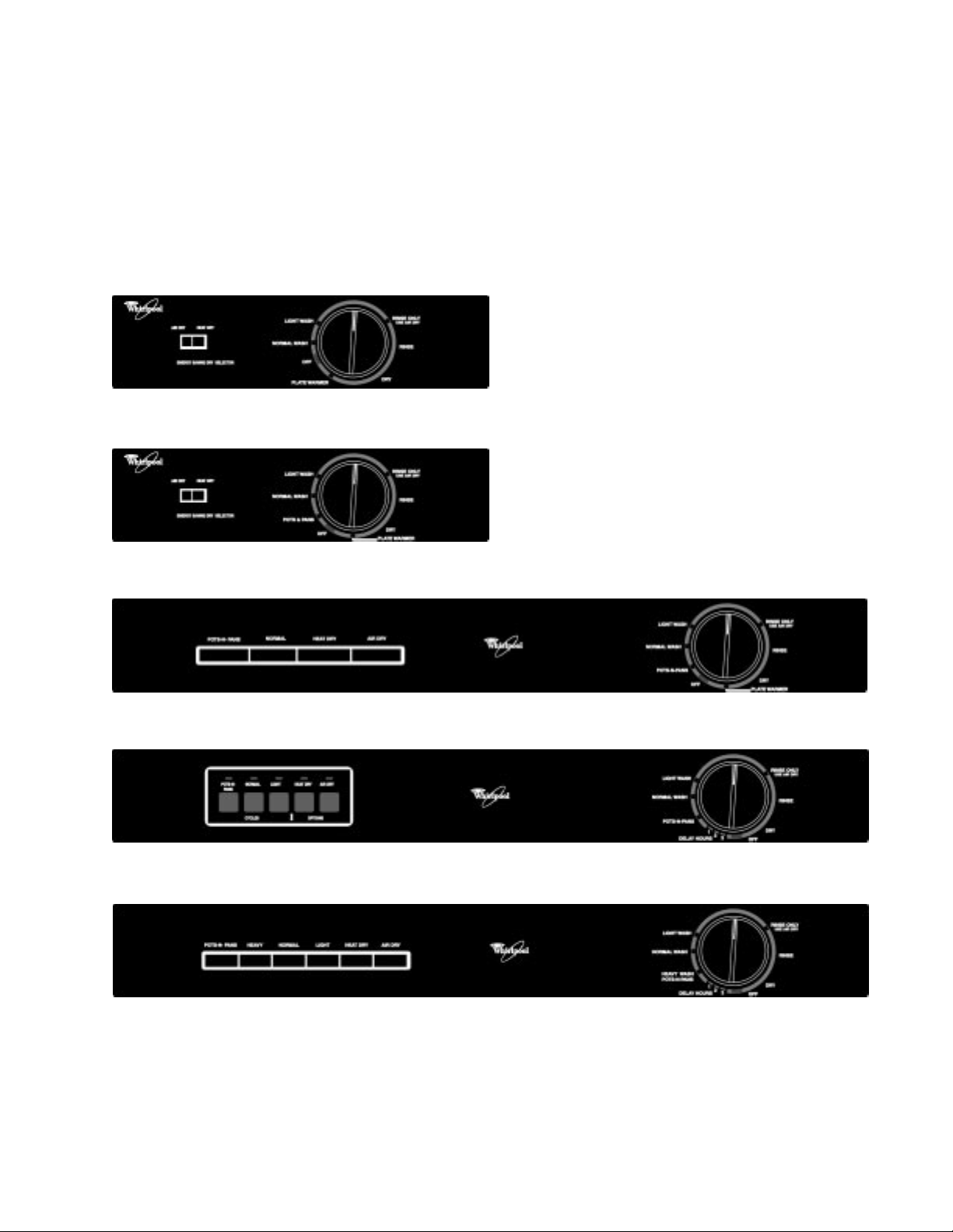
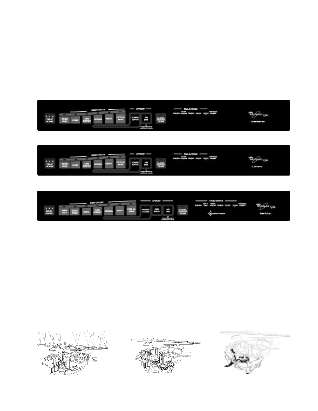
Console Configuration
DU800DWG, DU801DWG, DU805
DU810DWG
Section One
DU840DWG, DP840DWG
DU850DWG
DU890DWG
1
Special Feature
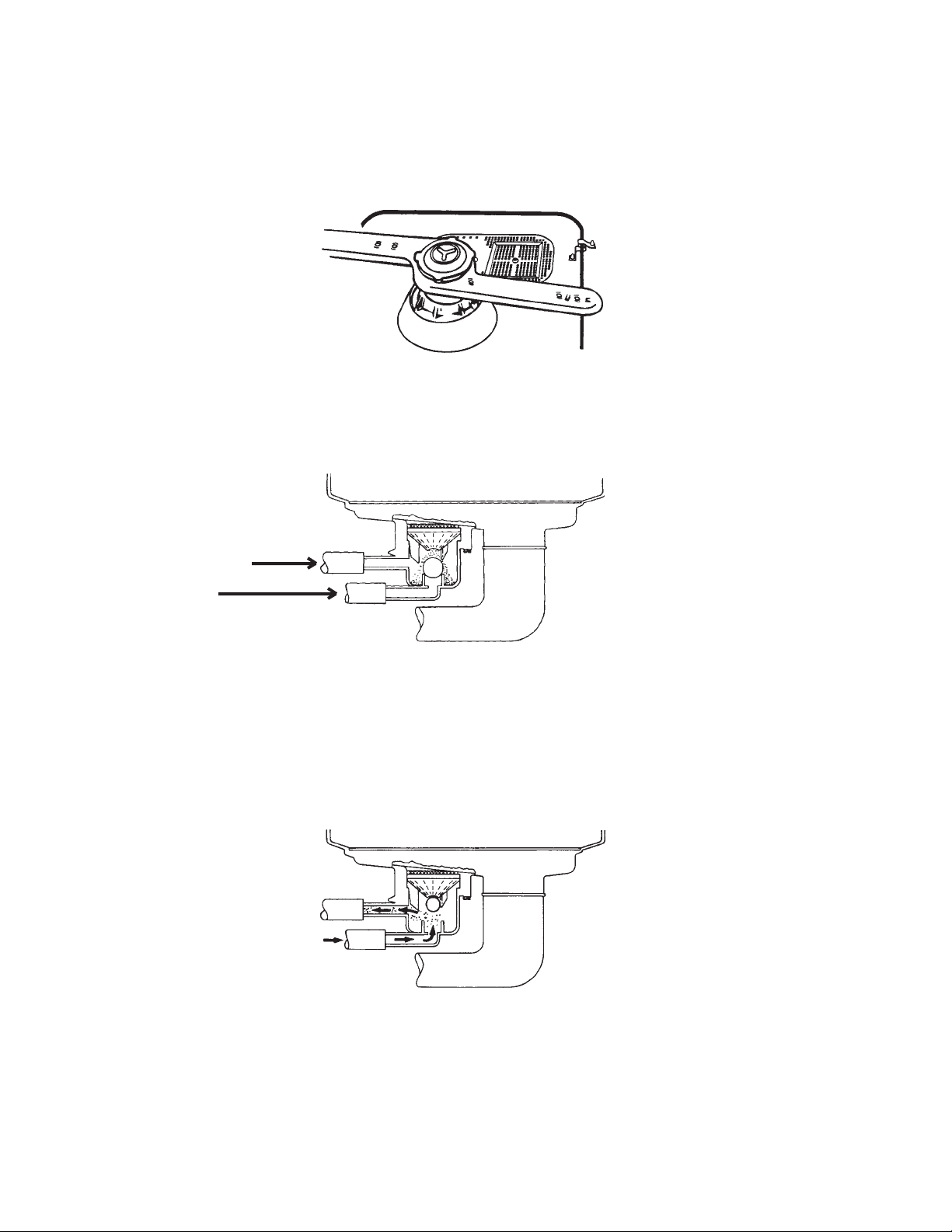
Soil Settler
This model is equipped with a soil settler system. The inlet to the soil settler funnel is located to the
right and just behind the lower spray arm assembly.
Since this inlet is located in an area that is relatively free of water turbulence, food particles washed
from the dishes can collect in this area and fall through the funnel and accumulate in the collector .
1-2)
Food particles continue to collect as long as the dishwasher is in the Wash mode.
(Fig. 1-1)
Fig. 1-1
(Fig.
COLLECTOR
PUMP INLET
HOSE
Fig. 1-2
When the Wash cycle is finished, the dishwasher will reverse the direction of the motor and enter the
Drain mode. Water is pumped into the port at the bottom of the soil collector during the Drain cycle
causing the ball in the collector to rise against the opening in the bottom of the funnel. Water flows
through and out of the collector through the top port and into the drain line.
collected during the Wash cycle are carried out with the drain water. When the Drain cycle ends and
the pump stops running, the ball settles to the bottom of the collector.
(Fig. 1-3)
Food particles
Fig. 1-3
2

COMPONENT ACCESS
! WARNING
ELECTRICAL SHOCK HAZARD
Disconnect electric supply from the dishwasher before servicing.
Replace all panels before operating.
Failure to do so could result in death or electrical shock.
Component Location
(Bottom Right-side
Rear of Tub)
3

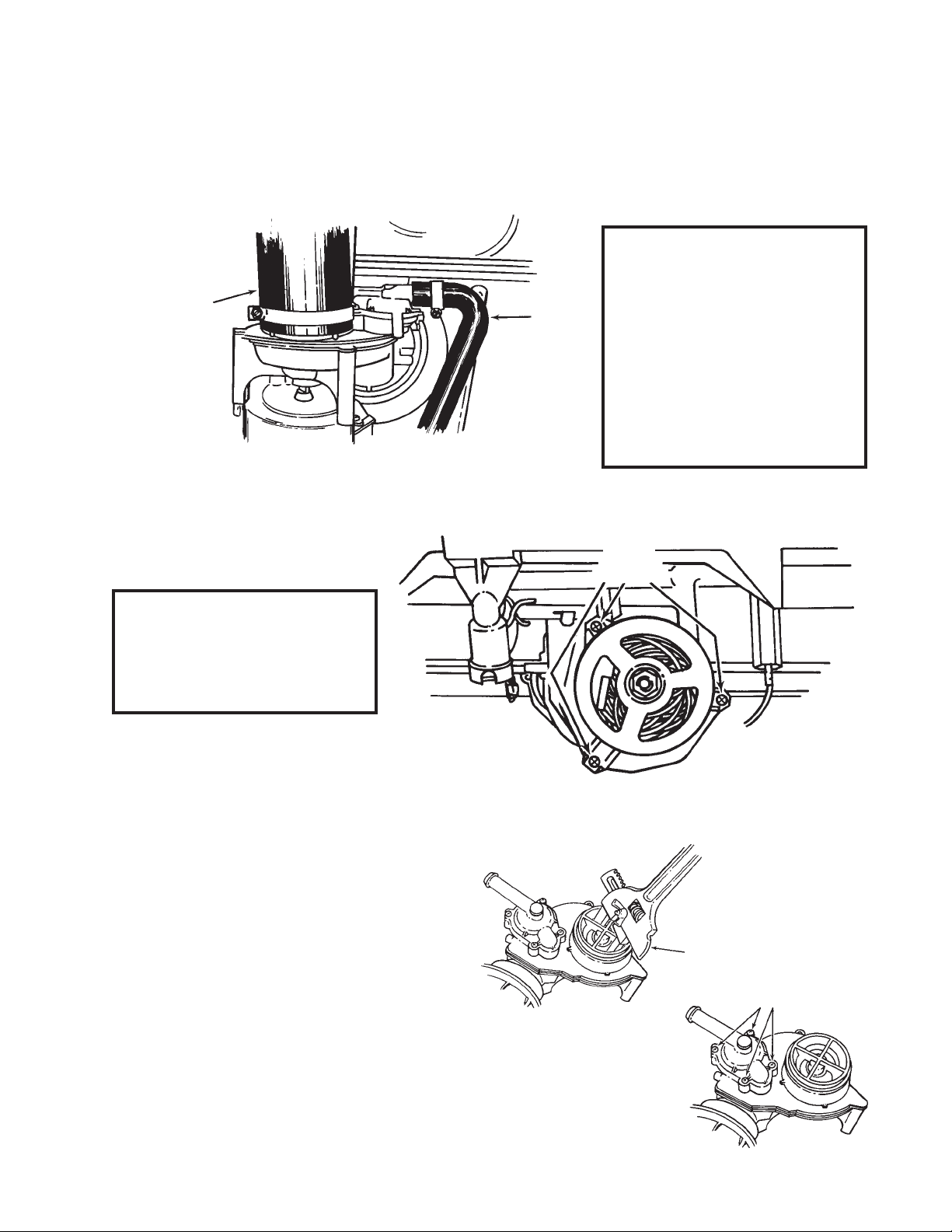
Removing the Spray Arm Assembly
1. Disconnect the dishwasher from the household electrical system.
2. Open the dishwasher door and remove the
lower rack.
3. Use an adjustable slip-nut wrench and loosen
the pump outlet nut. (Fig. 1-4)
4. Lift the spray arm assembly out of the pump fitting.
Fig. 1-4
5. The spray arm can be disassembled by removing
the retaining screw from the spray arm and removing the split-ring seal, the pump outlet nut
and the support and bearing assembly. (Fig. 1-5)
SPRA Y ARM ASSEMBLY
SPLIT RING SEAL
PUMP OUTLET NUT
SUPPORT & BEARING
RET AINING SCREW
Fig. 1-5
Removing the Pump and Motor Assembly
1. Disconnect the dishwasher from the household electrical system.
2. Lay the dishwasher on its back and disconnect the wiring harness connector from the motor.
3. Remove the motor support slip nut and remove the motor support.
MOTOR SUPPORT
SUPPORT
SPLIT NUT
Fig. 1-6
4
(Fig. 1-6)
4. Disconnect the drain hose from the drain valve by loosening the Hex-head screw on the hose
clamp. (Fig. 1-7)
5. Disconnect the pump inlet hose from the pump and motor assembly. (Fig. 1-7)
6. Remove the pump and motor assembly from the bottom of the dishwasher.
NOTE:Once the pump and mo-
tor assembly has been
PUMP INLET
HOSE
DRAIN
HOSE
removed from the tub,
the pump outlet grommet can be removed
from the inside of the
tub. Check the pump
outlet grommet for wear
or damage and replace
it if necessary.
Fig. 1-7
The motor can be removed from the pump assembly by removing the three T-20 Torx screws securing
the motor to the pump assembly.
(Fig. 1-8)
NOTE:When reinstalling the
motor make sure the
keyed motor shaft lines
up with the pump impeller.
Servicing the Pump Assembly
The pump impeller can be accessed by using
an adjustable slip-nut wrench to turn the
disk mount assembly counterclockwise.
Once the disk mount assembly is removed,
the impeller can be removed.
(Fig. 1-9)
SCREWS
Fig. 1-8
Fig. 1-9
TORX
SLIP-NUT WRENCH
TORX
SCREWS
The drain valve can be accessed by removing
the four (4) T-20 Torx screws securing the drain
outlet cover to the pump assembly. The drain
cover seal, diaphragm and diaphragm ring can
be removed and replaced.
(Fig. 1-10)
Fig. 1-10
5

Removing the Soil Settler Assembly
1. Disconnect the dishwasher from the household electrical system and lay the unit on its back.
2. Remove the four (4) Hex-head screws securing the soil settler assembly to the tub.
3. Disconnect the two (2) hoses from the soil settler collector.
4. Remove the funnel and funnel grate, check valve ball and seal from the soil settler collector.
(Fig. 1-11)
FUNNEL GRA TE
FUNNEL
CHECK VAL VE BALL
SEAL
CLAMPS
HOSE
Fig. 1-11
Removing the Heater Element
1. Disconnect the dishwasher from the household electrical system.
2. Disconnect the wiring harness connectors from the heater element terminals with a pair of
needlenose pliers.
3. Remove the two long Hex-head nuts securing the heater element to the tub.
4. Remove the heater element from the three (3) metal clips that hold it suspended inside the tub.
(Fig. 1-13)
HEATER
ELEMENT
HEA TER
ELEMENT
RET AINING
NUTS
(Fig. 1-12)
Fig. 1-12 Fig. 1-13
6
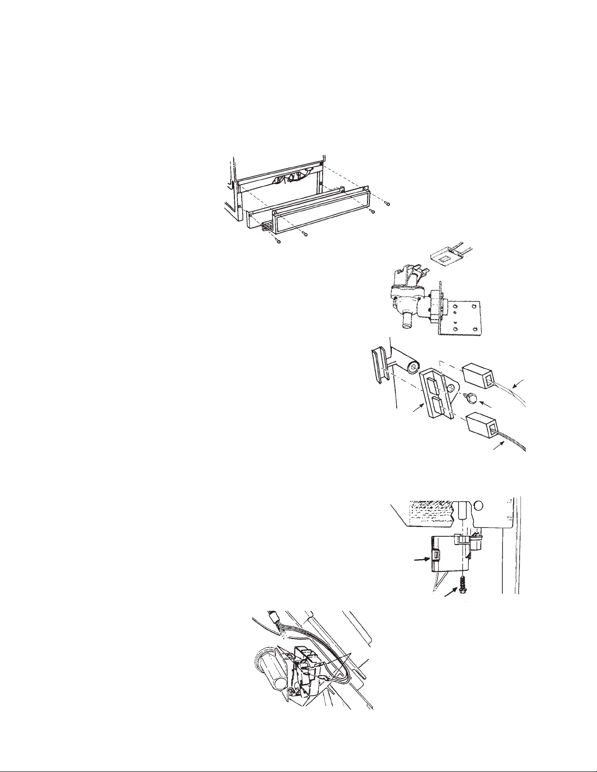
Removing the Water Inlet Valve
1. Turn off the water supply to the dishwasher.
2. Turn the timer knob clockwise to the NORMAL WASH position to energize the water inlet valve
and relieve water pressure in the line.
3. Turn the electrical supply to the dishwasher off and remove the toe panel and access panel.
(Fig. 1-14)
Fig. 1-14
4. Disconnect the wiring harness connector from the
water inlet valve terminals.
(Fig. 1-15)
5. Disconnect the water lines from the water inlet valve.
6. Remove the Hex-head screw securing the water inlet
valve to the tub support assembly.
Removing the Thermal Fuse
1. Turn the electrical supply to the dishwasher off and
remove the toe panel and access panel.
2. Disconnect the orange and white wires from the thermal
fuse terminals.
(Fig. 1-16)
3. Remove the Hex-head screw securing the thermal fuse
to the tub and remove the thermal fuse from the dishwasher.
Removing the Float Switch
1. Turn the electrical supply to the dishwasher off and
remove the toe panel and access panel.
2. Remove the Hex-head screw securing the float switch
to the tub.
3. Lift the float from the housing inside the tub.
4. Unsnap the float switch housing cover and disconnect
the two (2) wires from the terminals of the switch.
(Fig. 1-18)
(Fig. 1-17)
THERMAL
FUSE
FLOAT
SWITCH
HOUSING
RETAINING
SCREW
Fig. 1-15
Fig. 1-16
WHITE
WIRE
RET AINING
SCREW
ORANGE
WIRE
Fig. 1-17
Fig. 1-18
TERMINALS
WIRES
SWITCH COVER
7
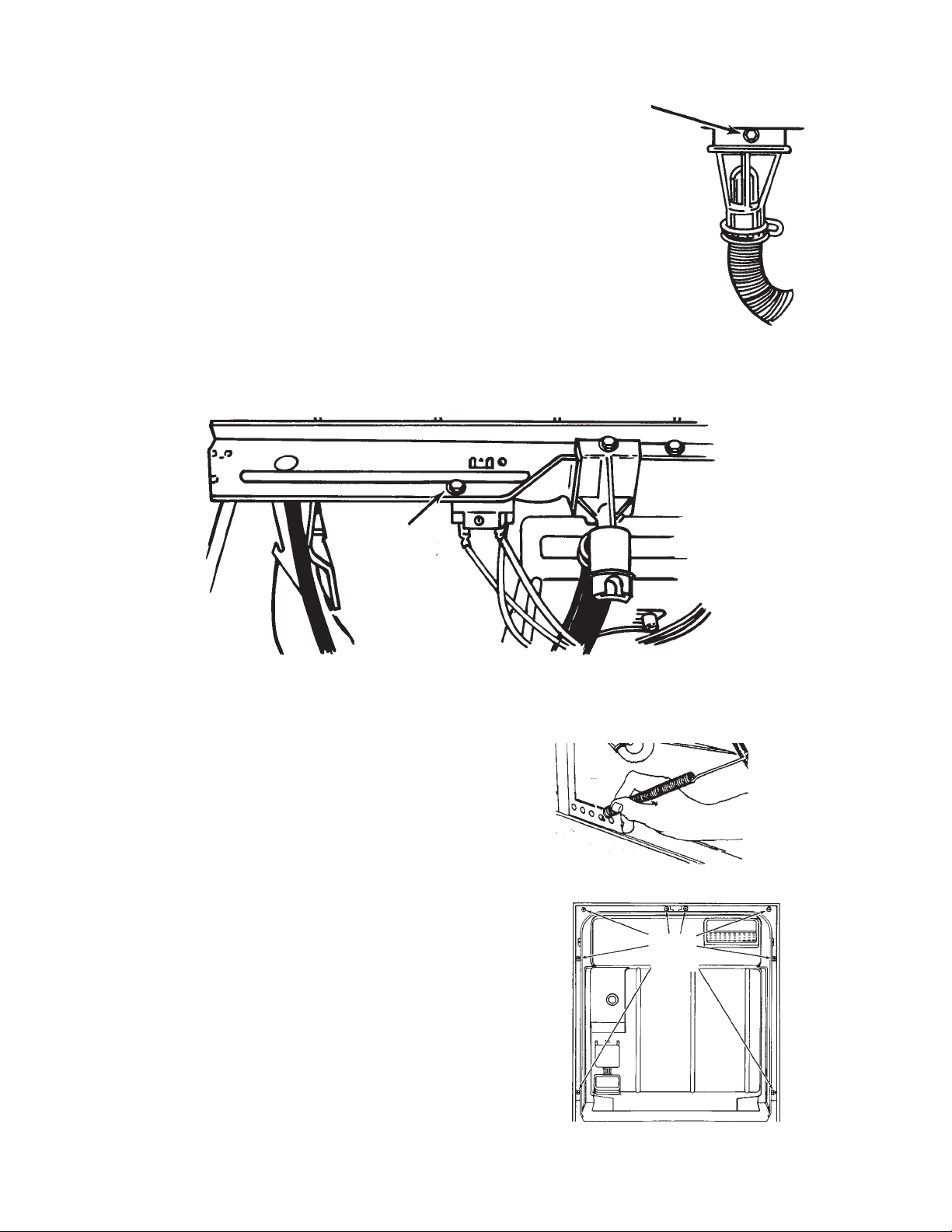
Removing the Check V alve
1. Remove the toe panel and access panel from the
bottom of the dishwasher.
RETAINING
SCREW
2. Remove the hoses from the check valve.
Fig. 1-19
3. Remove the Hex-head screw securing the check valve to
the tub support.
(Fig. 1-19)
Removing the Motor Relay
1. Disconnect the dishwasher from the electrical supply and remove
the toe panel and access panel from the bottom of the dishwasher.
2. Disconnect the three (3) wiring harness connectors from the motor relay terminals.
3. Remove the Hex-head screw securing the motor relay to the tub support.
RET AINING
SCREW
(Fig. 1-20)
Accessing Components Inside the Door
1. Disconnect the dishwasher from the electrical
supply and remove the toe panel and access
panel from the bottom of the dishwasher.
2. Disconnect the end of the door springs
from the door spring tension adjustment
holes in the frame runner. Note which
holes were used and reattach the door
springs in the same holes when the repairs
are complete.
3. Open the dishwasher door and remove the
eight (8) T-15 Torx screws securing the inner
door panel from the door frame.
4. Remove the timer cover by releasing the
two (2) retaining tabs at each end from the
door frame.
(Fig. 1-21)
(Fig. 1-22)
Fig. 1-20
Fig. 1-21
T-15
TORX
Fig. 1-22
8
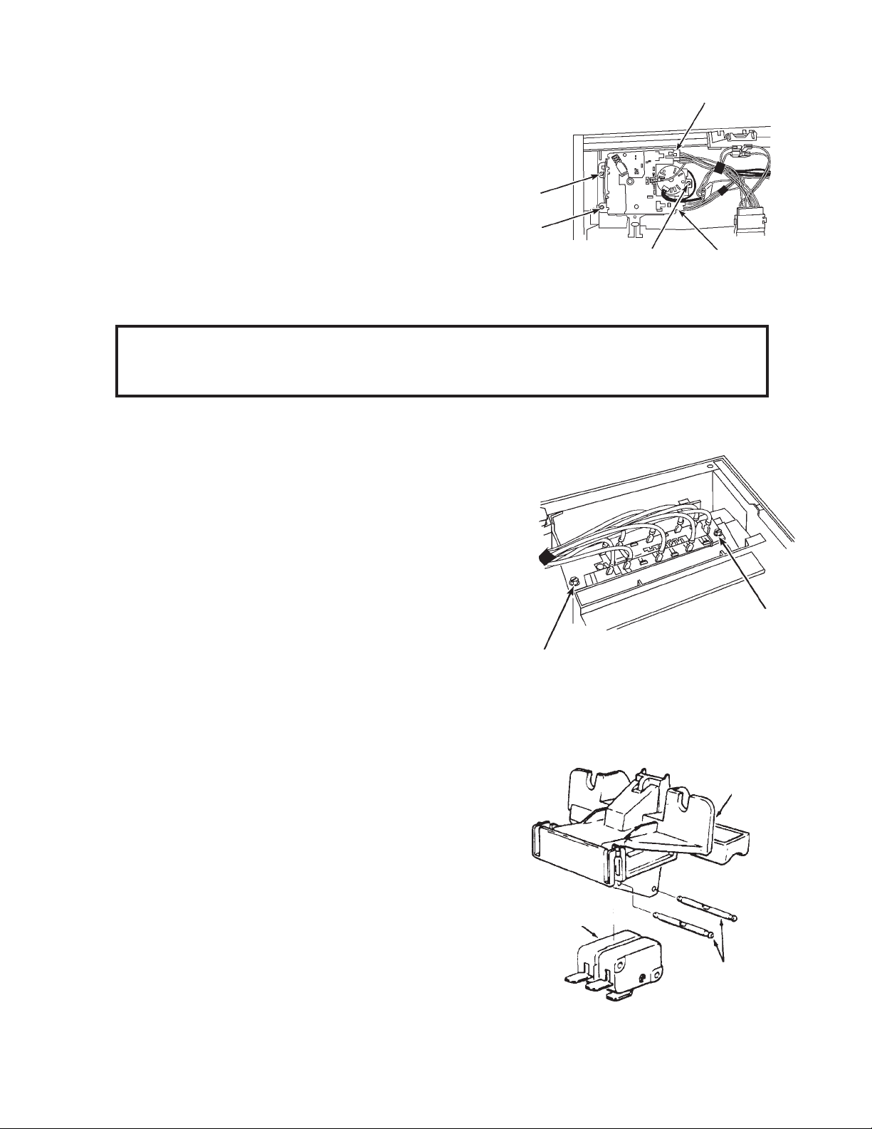
Removing the Timer
1. Disconnect the dishwasher from the electrical
supply and remove the toe panel and access
panel from the bottom of the dishwasher and
the inner door panel.
Screw
2. Disconnect the wiring harness connectors from
the timer terminals.
(Fig. 1-23)
3. Remove the three (3) Hex-head screws securing
the timer to the door frame.
(Fig. 1-23)
The timer,
Screw
Screw
Fig. 1-23
cam and cam follower can now be removed.
NOTE:When reinstalling the cam, be sure it is aligned with the keyed shaft of the timer.
When reinstalling the timer, be sure the cam follower post is positioned inside the
cam’s groove.
Removing the Switch Assembly
1. Disconnect the dishwasher from the electrical
supply and remove the toe panel and access
panel from the bottom of the dishwasher and
the inner door panel.
Wiring Harness
Connector
Wiring
Harness
Connector
2. Disconnect the harness wires from the spade
connectors on the switch assembly.
(Fig. 1-24)
3 . Remove the two (2) Hex-head screws securing
the switch assembly to the door frame.
The switch assembly can now be removed.
(Fig. 1-24)
Screw
Fig. 1-24
Removing the Door Latch Switches
1. Disconnect the dishwasher from the electrical supply and remove the toe panel and access
panel from the bottom of the dishwasher and the inner door panel.
2. Disconnect the wiring harness connectors from
the door latch switch terminals.
3. Unclip the handle and latch assembly from the
door frame.
4. To remove the switches from the handle and latch
assembly, push the two (2) retaining pins out of the
holes and remove the switches.
SWITCHES
(Fig. 1-25)
HANDLE &
ASSEMBLY
Screw
LATCH
RETAINING
PINS
Fig. 1-25
9
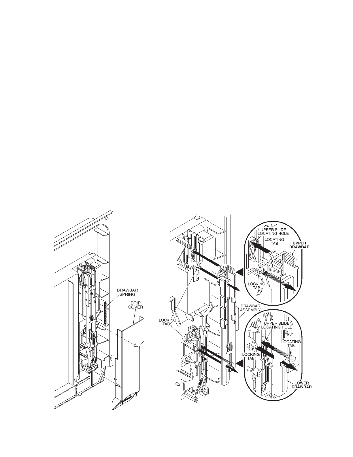
Dishwasher Dispenser Disassembly
1. Remove the drawbar spring.
2. Align the lower drawbar holes with the locking tabs and remove the upper and lower drawbars.
As you do, note the locating tabs behind them and how they align with their respective locating
holes.
3. Slide the drawbars apart.
4. Turn the wet agent cap and seal assembly counterclockwise and remove it.
5. Remove the seal from the cap.
6. Use Special Tool - Part No. 303918 or a ¾” socket to press over the attaching tabs
in the wet agent cap opening. Remove wet agent dispenser assembly.
7. Remove wet agent dispenser actuator by spreading the two (2) locking tabs.
8. Remove the upper and lower slides from the wet agent dispenser actuator.
9. Remove the diaphragm spring and diaphragm.
10. Use a screwdriver to gently release the lower tab and remove the detergent door
actuator assembly. As you do, note the position of the door latch level through the hole in the
lower slide.
11. Remove the upper slide, the slide spring and the lower slide.
(Fig. 1-27)
(Fig. 1-31)
(Fig. 1-26)
(Fig. 1-28)
(Fig. 1-29)
(Fig. 1-30)
(Fig. 1-32)
Fig. 1-26 Fig. 1-27
10
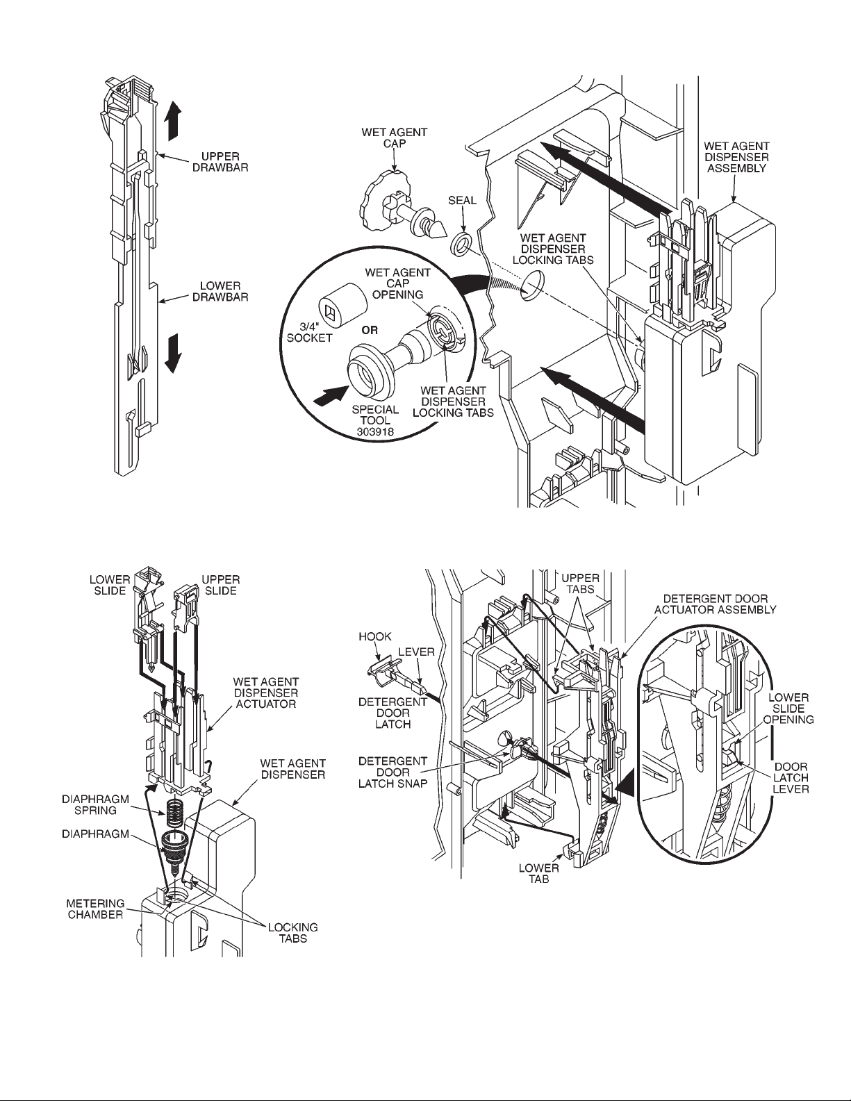
Fig. 1-28
Fig. 1-29
Fig. 1-30
Fig. 1-31
11
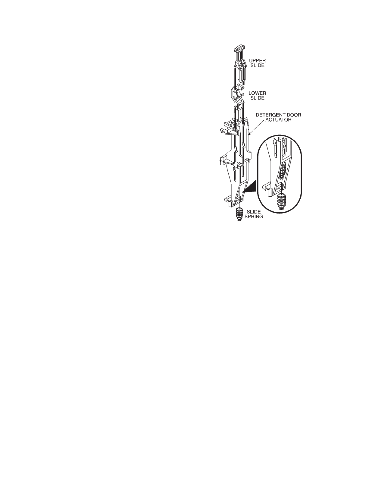
Dishwasher Dispenser Assembly
1. Assembly the upper slide, slide spring
and lower slide to the detergent
door actuator.
2. Pass the detergent door latch lever
through the panel making sure to turn the
hook of the latch toward the detergent
door. Snap the detergent door latch snap
onto the door latch lever.
3. The door latch lever must pass through
the opening in the lower slide. Press the
actuator assembly into position until the
upper and lower tabs engage.
4. Insert the diaphragm and diaphragm
spring into the wet agent dispenser . Seat
the diaphragm flush with the surface of
the dispenser.
5. Install the upper and lower slides into the
wet agent dispenser actuator.
6. Press the wet agent dispenser actuator
into position on the dispenser so the locking tabs engage.
(Fig. 1-32)
(Fig. 1-31)
(Fig. 1-30)
Fig. 1-32
7. Press the wet agent dispenser assembly
into position so the locking tabs engage
the wet agent cap opening. No tool is
needed for assembly.
8. Install the seal on the wet agent cap.
9. Insert the wet agent cap. Turn it clockwise and close it.
10. Slide the upper and lower drawbars
together.
11. Move all slides in both assemblies fully
down. Keep the drawbars slid fully together and align the drawbar holes over
the locking tabs. Look behind the draw
bars and make sure to engage the locating tabs with their respective locating
holes. Press the drawbars into position
and slide them upward behind the locking
tab ears.
12. Install the drawbar spring.
(Fig. 1-28)
(Fig. 1-27)
(Fig. 1-29)
(Fig. 1-26)
13. Install the drip cover by snapping it into
place.
12
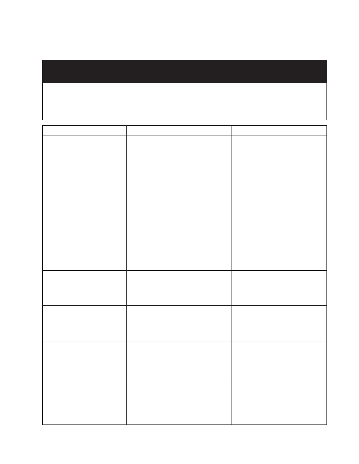
SOLUTIONS TO COMMON PROBLEMS
DIAGNOSING PROBLEM COMPONENTS
PRECAUTIONS TO BE OBSERVED WHILE DIAGNOSING
PROBLEM COMPONENTS
Disconnect electric power from the dishwasher.
Voltage checks should be made by inserting meter probes beside the wires in the connector blocks with the electric power source on
and the connector block plugged in.
Resistance checks should be made on components with the electric power off and the connector blocks disconnected.
COMPONENT SCHEMATI C TESTING PROCEDURE RESULTS
Motor Start Relay
1. Disconnect the wire connectors and
remove relay from unit.
2. Set VOM meter on the Rx1 scale.
3. Set the relay upright.
4. Measure resistance between blue and
violet contacts.
5. Turn relay upside-down.
6. Measure resistance between blue and
violet contacts.
1. Relay upright - meter should read
º (infinity.)
2. Relay upside-down - meter should
read less than two (2)Ω.
Drive Motor
Thermal Fuse
Heater Element
Fill Valve
1. Disconnect the motor wiring harness
plug from the motor connector.
2. Set VOM meter on the Rx1 scale.
3. Connect one probe to the white/violet
connector.
4. Connect the other probe to the blue/
white connector.
5. Connect the meter probe to the yellow
connector.
6. Connect the probe to the grey
connector.
1. Disconnect wires connectors from the
thermal fuse terminals.
2. Set VOM meter to read Rx1 scale.
3. Measure resistance between thermal
fuse terminals.
1. Disconnect the wire connectors from
the heater element terminals.
2. Set VOM meter to read Rx1 scale.
3. Measure resistance between heater
element terminals.
1. Disconnect the wiring harness plug
from the fill valve connector.
2. Set VOM meter to read Rx1 scale.
3. Measure resistance between the
terminals of the fill valve.
1. White/violet to blue/white - meter
should read 5 - 7Ω.
2. White/violet to yellow - meter
should read 5 - 7Ω.
3. White/violet to gray - meter
should read 5 - 7Ω.
1. Meter should read 0Ω.
1. Meter should read 25 - 35Ω.
1. Meter should read approximately
700Ω.
Overfill Switch
1. Disconnect the wires connectors from
the overfill switch terminals.
2. Set VOM meter to read Rx1 scale.
3. Measure resistance between switch
terminals.
4. Block the float in the UP (full) position
and measure resistance again.
13
1. Float DOWN - meter should read
0Ω.
2. Float UP - meter should read
º (infinity).

COMPONENT SCHEMATIC TESTING PROCEDURE RESULTS
Timer Motor
1. Disconnect the Wiring harness
connector from the timer assembly.
2. Set VOM meter on the Rx1 scale.
3. Measure resistance between timer
motor terminals.
1. Meter should read 1800 - 3000Ω.
Timer
Dispenser Mechanism
1. Disconnect the wiring harness
connector from the timer assembly.
2. Set VOM meter on the Rx1 scale.
3. Connect one probe to contact 31.
(Tan)
4. Connect the other probe to the timer
contact to be tested.
5. Manually advance the timer until the
contact closes.
6. Manually advance the timer until the
contact opens.
1. Remove the front door panel.
2. Remove the drip cover.
3. Latch the detergent door closed.
4. Manually advance the timer through a
complete cycle slowly.
1. Contact CLOSED - meter should
read 0Ω.
2. Contact OPEN - meter should
read º (infinity).
1. At 12 o’clock position - Draw bars
will move upward causing the
detergent actuator assembly to
release the latch and detergent
cup should open.
2. At 4 o’clock position - Draw bars
will again move upward causing
the wetting agent actuator to
release wetting agent.
3. From the 6 o’clock position to the
8 o’clock position the draw bars
are driven down to reset the
mechanism.
14

TROUBLESHOOTING GUIDE
PRECAUTIONS TO BE OBSER VED WHILE TROUBLESHOOTING
AND DIAGNOSING PROBLEMS
Always check wiring harness and connectors before initiating any test procedures.
Disconnect electric power from the dishwasher before touching the printed circuit boards or re-seating wire connectors.
Voltage checks should be made by inserting meter probes beside the wires in the connector blocks with the electric power source on
and the connector block plugged in.
Resistance checks should be made on components with the electric power off and the connector blocks disconnected.
PROBLEM POSSIBLE CAUSES CORRECTION/TEST
Dishwasher does not run or
stops during a cycle
Dishwasher will not fill
Dishwasher will not drain
1. Door is not latching properly.
2. Child lock is "ON".
3. Wash Cycle not set properly.
4. Household fuse blown or circuit
breaker tripped.
5. Washer is not wired into a circuit with
proper voltage.
1. Overflow protection float is stuck in
"up" position.
2. Fill valve is inoperable.
3. Open timer contacts.
1. Air gap (if installed) is clogged.
2. Pump motor is inoperable.
3. Open timer contacts.
1. Check to make sure handle link
is properly seated in door latch
assembly. Check that the door
switch is opening and closing
properly.
2. Turn child lock "OFF"
3. Review setting Wash Cycles in
the Use and Care Guide.
4. Have a qualified electrician check
the circuit breaker or fuse.
5. Have customer call a qualified
electrician.
1. Check that the overflow
protection float is free to move
"up" and "down". Check that the
overfill switch in opening and
closing properly.
2. Check for continuity between
contacts on fill valve.
3. Test timer contacts.
1. Follow air gap manufacturer's
direction for cleaning.
2. Disconnect pump motor from
wiring harness and check for
continuity.
3. Test timer contacts.
Dishwasher will not
dry dishes
1. Heater element burned out.
2. Hi-limit thermostat inoperable.
3. Open circuit between timer and
heater.
15
1. Check for continuity between the
terminals of the heater element.
2. Check for continuity between
terminals of the hi-limit
thermostat.
3. Check for continuity between
timer switch contacts and heater.

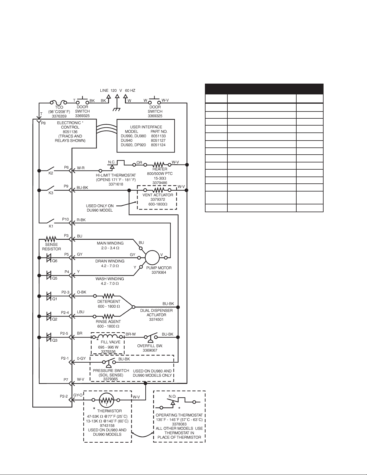
Wiring Diagram
Models DU800DWG, DU801DWG, DU805DWG
TECHNICAL INFORMA TION
SCHEMATIC SHOWN WITH DOOR SWITCHES CLOSED,
ALL CONT ACTS OPEN
16

Cycle Timing Chart
17

Wiring Diagram
Model DU810DWG
SCHEMATIC SHOWN WITH DOOR SWITCHES CLOSED,
ALL CONT ACTS OPEN
18

Cycle Timing Chart
19

Wiring Diagram
Models DU840DWG, DP840DWG
SCHEMATIC SHOWN WITH DOOR SWITCHES CLOSED,
ALL CONT ACTS OPEN
20

Cycle Timing Chart
21

Wiring Diagram
Model DU850DWG
SCHEMATIC SHOWN WITH DOOR SWITCHES CLOSED,
ALL CONT ACTS OPEN
22

Cycle Timing Chart
23

Wiring Diagram
Model DU890DWG
SCHEMATIC SHOWN WITH DOOR SWITCHES CLOSED,
ALL CONT ACTS OPEN
24

Cycle Timing Chart
25

--NOTES --
26

POWER CLEAN FILTER MODELS
WITH TOWER WATER FEED
Models: DU910PFG, DP920PFG, DU920PFG
THEORY OF OPERATION
Console Configuration
Model DU910PFG
Models DP920PFG, DU920PFG
Section T wo
Fig. 2-1
POWER CLEAN FILTER Pump and Motor Operation
1. Once the tub has filled with hot water the motor begins to rotate forcing the water up through the
pump chamber and out through the spray arms. Two spray jets on the underside of the lower spray
arm direct water down onto the fine mesh screen of the pump housing to clear soils that may
collect there during the wash cycle.
2. As water and soils return to the lower pump area, the chopper blade grinds the particles into
smaller sizes that then pass through the perforated plate into the upper chamber of the pump. The
pump impeller causes the soil ladened water to be lifted and moved to the outer edges of the pump
chamber where they are forced into the separator. Clean water is then forced up through the spray
arms and fine mesh screen.
3. When the drain cycle begins, the drive motor changes direction. This relieves the pressure on the
two check balls, opening the drain system.
4. Water is pumped from the tub carrying soils from the separator into the drain sump of the pump.
(Fig. 2-4)
5. Soiled water is pumped out of the dishwasher through the check valve and drain hose.
(Fig. 2-3)
(Fig. 2-2)
(Fig. 2-4)
Fig. 2-2
Fig. 2-4Fig. 2-3
27

PROGRAM
SWITCHES
COMPONENT ACCESS
INDICATOR
LIGHTS
TIMER
DETERGENT
AND RINSE AID
DISPENSER
ASSEMBLY
LA TCH
ASSEMBLY
FILL
VALVE
MOTOR
RELAY
FLOA T
SWITCH
OPERA TING
THERMOSTAT
(Attached to bottom
of pump housing)
HEATER
PUMP AND
MOTOR
ASSEMBLY
HI LIMIT
THERMOSTA T
28

Removing the Heater Element
From beneath the cabinet:
1. Remove the front access panel. (See Removing the Outer Door Panel)
2. Pull the spade connectors off the heater element terminals.
3. Unscrew the two (2) nuts securing the heater element to the bottom of the tub.
(Fig. 2-5)
From inside the tub:
4. Remove the lower dish rack.
Fig. 2-5
5. Remove the lower spray arm.
6. Slide the metal disks from the metal clips
securing the left and right sides of the heater
element.
. 7. Carefully lift the heater element from the unit.
Replacing the Heater Element
Element Retaining Nuts (2)
From inside the tub:
1. Carefully place the terminal ends of the heater element through the two (2) holes at the
bottom rear of the cabinet.
2. Slide the metal disks into the clips to secure the left and right sides of the heater element.
3. Replace the lower spray arm.
4. Replace the lower dish rack.
From underneath the cabinet:
5. Secure the heater element in place with two (2) nuts. Be sure the element is seated firmly
against the tub.
6. Slide the spade connectors onto the heater element terminals.
7. Replace the front access panel.
Removing the Pump Motor Assembly
1. Unscrew and remove the nozzle cap
and remove the nozzle bearing and
spray arm.
(Fig. 2-6)
NOZZLE BEARING
29
SPRAY ARM
NOZZLE
CAP
Fig. 2-6

2. Disconnect the wiring harness from the motor harness plug.
3. Rubber clamps secure the pump and motor assembly to the tub. Rotate these inward 90°.
(Fig. 2-7)
4. Remove the drain hose and clamp from the check valve and unscrew the check valve
from the pump.
(Fig. 2-8)
5. Remove the tuned sound absorber. Use an open-end wrench to loosen the shaft from the
motor. Do not loosen the sound absorber by torquing on the large tuned resonator.
-- NOTE --
A small container will be required to catch water from the drain hose after removal.
Check Valve
Drain Hose
Clamp
Tuned
Sound
Absorber
Clamp
Shown Rotated
Inward 90°
Fig. 2-7
Fig. 2-8
6. Remove the pump and motor assembly by pulling up through the inside of the tub.
Fig. 2-9
Drain
Hose
(Fig. 2-9)
Servicing the Operating Thermostat
The operating thermostat is secured to the bottom
of the pump housing.
1. Disconnect the two (2) wiring harness leads
from the terminals on the thermostat.
2. Remove the two (2) Hex-head screws
securing the thermostat to the pump housing.
(Fig. 2-10)
30
Operating
Thermostat
Fig. 2-10

ACCESSING COMPONENT INSIDE THE DISHWASHER DOOR
Removing Access and Outer Door
Panels
1. Loosen but do not remove the two (2) toe
panel screws below the access panel. Remove and set aside the two (2) screws above
the access panel.
2. Remove the access panel assembly by sliding it upward to clear the loosened screws.
(Fig. 2-11)
3. Remove the two (2) screws from the bottom
of the outer door panel.
4. Pull the bottom of the outer door panel outward and slide it down approximately ¼” to
½”. The panel will then be free for removal.
(Fig. 2-11, inset)
5. Remove the existing door insulation. Access
to the detergent and rinse aid dispensers is
now possible.
(Fig. 2-11)
(Fig. 2-11)
Removing the Inside Door Panel
1. Disconnect the dishwasher from the electrical
supply.
2. Disconnect the end of the door springs
from the door spring tension adjustment
holes in the frame runner.
3. Open the dishwasher door and remove the
eight (8) T-15 Torx screws securing the inner
door panel from the door frame.
4. Slide the inner door panel back toward the dish-
washer to disengage the spring loaded locking
tab from the door panel, then lift the door panel
away from the door.
(Fig. 2-13)
4. Remove the control cover .
(Fig. 2-12)
Fig. 2-11
Fig. 2-12
Inner Door
Panel
Fig. 2-13
SLIDE INNER DOOR
PANEL T OWARD
DISHWASHER
T-15
TORX
Spring Loaded
Locking T ab
31

Replacing the Spring Loaded Locking T ab
The inner door panel is held in place by a spring loaded locking tab located on the door frame rail, just
below the console.
To remove this assembly, remove the spring and slide the locking tab back until the locating tab is in
the key hole.
(Fig. 2-15)
(Fig. 2-14)
Then lift the locking tab up. T o replace the assembly, reverse this procedure.
Locking T ab
Assembly
Fig. 2-15
Fig. 2-14
32

TROUBLESHOOTING GUIDE
Model DU910PFG
PRECAUTIONS TO BE OBSER VED WHILE TROUBLESHOOTING
AND DIAGNOSING PROBLEMS
Always check wiring harness and connectors before initiating any test procedures.
Disconnect electric power from the dishwasher before touching the printed circuit boards or re-seating wire connectors.
Voltage checks should be made by inserting meter probes beside the wires in the connector blocks with the electric power source on
and the connector block plugged in.
Resistance checks should be made on components with the electric power off and the connector blocks disconnected.
PROBLEM POSSIBLE CAUSES CORRECTION/TEST
Dishwasher does not run or
stops during a cycle
Dishwasher will not fill
Dishwasher will not drain
1. Door is not latching properly.
2. Child lock is "ON".
3. Wash Cycle not set properly.
4. Household fuse blown or circuit
breaker tripped.
5. Washer is not wired into a circuit with
proper voltage.
1. Overflow protection float is stuck in
"up" position.
2. Fill valve is inoperable.
3. Open timer contacts.
1. Air gap (if installed) is clogged.
2. Pump motor is inoperable.
3. Open timer contacts.
1. Check to make sure handle link
is properly seated in door latch
assembly. Check that the door
switch is opening and closing
properly.
2. Turn child lock "OFF"
3. Review setting Wash Cycles in
the Use and Care Guide.
4. Have a qualified electrician check
the circuit breaker or fuse.
5. Have customer call a qualified
electrician.
1. Check that the overflow
protection float is free to move
"up" and "down". Check that the
overfill switch in opening and
closing properly.
2. Check for continuity between
contacts on fill valve.
3. Test timer contacts.
1. Follow air gap manufacturer's
direction for cleaning.
2. Disconnect pump motor from
wiring harness and check for
continuity.
3. Test timer contacts.
Dishwasher will not
dry dishes
1. Heater element burned out.
2. HI-limit thermostat inoperable.
3. Open circuit between timer and
heater.
33
1. Check for continuity between the
terminals of the heater element.
2. Check for continuity between
terminals of the hi-limit
thermostat.
3. Check for continuity between
timer switch contacts and heater.

Wiring Diagram
TECHNICAL INFORMA TION
Model DU910PFG
SCHEMATIC SHOWN WITH DOOR SWITCHES CLOSED,
ALL CONTACTS OPEN
34

Strip Circuits
HEAT DRY (Steps 30 - 44)
NO HEAT DRY
(Switch H OPEN)
DRAIN (Steps 8, 13, 21 - 22, 29, 50)
WASH (Steps 2 - 7, 10 - 12, 15 - 20, 24 - 28, 49)
WATER HEATING (Steps 6 - 7, 18 - 19, 23 - 24)
FILL (Steps 1, 9, 14, 23, 48)
Harness Terminal Block (Wire End)
Black White
35

Cycle Timing Charts
36

TROUBLESHOOTING GUIDE
Models DP920PFG & DU920PFG
PRECAUTIONS TO BE OBSER VED WHILE TROUBLESHOOTING
AND DIAGNOSING PROBLEMS
Always check wiring harness and connectors before initiating any test procedures.
Disconnect electric power from the dishwasher before touching the printed circuit boards or re-seating wire connectors.
Voltage checks should be made by inserting meter probes beside the wires in the connector blocks with the electric power source on
and the connector block plugged in.
Resistance checks should be made on components with the electric power off and the connector blocks disconnected.
TROUBLESHOOTING GUIDE
PROBLEM POSSIBLE CAUSES CORRECTION/TEST
Dishwasher does not run or
stops during a cycle
Dishwasher will not fill
Dishwasher will not drain
Dishwasher will not
dry dishes
1. Door is not latching properly.
2. Child lock is "ON".
3. Wash Cycle not set properly.
4. Household fuse blown or circuit
breaker tripped.
5. Washer is not wired into a circuit with
proper voltage.
1. Overflow protection float is stuck in
"up" position.
2. Fill valve is inoperable.
3. Control board is inoperable.
1. Air gap (if installed) is clogged.
2. Pump motor is inoperable
3. Control board is inoperable.
1. Heater element burned out.
2. Hi-limit thermostat inoperable.
1. Check to make sure handle link
is properly seated in door latch
assembly. Check that the door
switch is opening and closing
properly.
2. Turn child lock "OFF"
3. Review setting Wash Cycles in
the Use and Care Guide.
4. Have a qualified electrician check
the circuit breaker or fuse.
5. Have customer call a qualified
electrician.
1. Check that the overflow
protection float is free to move
"up" and "down". Check that the
overfill switch in opening and
closing properly.
2. Check for continuity between
contacts on fill valve.
3. Check for 110VAC between P2-5
and P12-3.
1. Follow air gap manufacturer's
direction for cleaning.
2. Disconnect pump motor from
wiring harness and check for
continuity between V & BU, V &
GY and V & Y.
3. Check for 110VAC between P10
and P3, P10 and P5 and P10
and P4.
1. Check for continuity between the
terminals of the heater element.
Check for 110VAC between P6
and P8.
2. Check for continuity between
terminals of the hi-limit
thermostat.
37
WIRING DIAGRAM
TECHNICAL INFORMA TION
Models DP920PFG & DU920PFG
CONNECTOR PIN OUT
Pin No. DESCRIPTION
P1
Ribbon Cable to User Interface
P2-1
P2-2
P2-3
P2-4
P2-5
P10
Pressure Switch (Soil Sense)
P3
P4
Motor Auxiliary Winding - Wash
P5
Motor Auxiliary Winding - Drain
P6
P7
P8
Switched L1 to Vent, Fill Valve,
P9
Dual Dispenser & Pressure Sw.
Switched L1 to Motor Common
Thermistor/Thermostat
Detergent Dispenser
Rinse Agent Dispenser
Fill Valve
Motor Main Winding
Switch L1 to Heater
AC Neutral
L1
Wire Color
O - GY
GY - O
O - BK
LBU
BR
BU
Y
GY
W - R
W - V
T
BU - BK
R - BK
38

STRIP CIRCUITS
39

STRIP CIRCUITS
CYCLE TIMING CHART
40

CYCLE TIMING CHART NOTES
Note 1: Pre-Wash Sense Interval
Pressure switch contact closure at any time during this interval causes the
cycle to jump to interval 37. Immediately. For the normal cycle, the heater is
“off” during this interval. For the heavy and pots-n-pans cycles the heater is
“on” during this interval. The power scour option changes this interval to a 16
minute heated wash interval for all 3 cycles (normal, heavy and pots-n-pans).
If the water temperature reaches 140ºF or the thermostat closes. The heater
is turned “off”. Time continues to elapse and all other output states remain the
same until the prescribed interval time has elapsed.
Note 2: Pre-Wash Thermal Hold
This thermal hold is only executed during the heavy and pots-n-pans cycles.
The thermal hold setpoint is 140ºF or thermostat contact closure and the default time is 25 minutes.
Pressure switch contact closure at any time during this interval causes the
cycle to jump to interval 37. Immediately.
Note 3: Pre-Rinse Sense Interval
Pressure switch contact closure at any time during this interval causes the
cycle to jump to interval 31. Immediately. For the normal cycle, the heater is
“off” during this interval. For the heavy and pots-n-pans cycles the heater is
“on” during this interval. The power scour option changes this interval to a
heated wash interval for the normal cycle. If the water temperature reaches
140ºF or the thermostat closes. The heater is turned “off”. Time continues to
elapse and all output states remain the same until the prescribed interval time
has elapsed.
Note 4: Pre-Rinse Thermal Hold
This thermal hold is only executed during the heavy and pots-n-pans cycles
and only occurs if the pressure switch trips during the sense or thermal hold
intervals of the pre-wash the thermal hold setpoint is 140ºF or thermostat contact closure and the default time is 20 minutes. Pressure switch contact closure at any time during this interval causes the cycle to jump to interval 31.
Immediately.
Note 5: Main Wash Thermal Hold
This thermal hold is automatic for the pots-n-pans and heavy cycles (set point
= 140ºF). For the normal cycle. This thermal hold is invoked by selecting the
power scour or high temp wash options (Set Point = 140ºF) or as a result of
the pressure switch tripping during the pre-wash (Set Point = 130ºF). For the
low energy wash and quick wash cycles. This thermal hold is invoked by selecting the high temp wash option (Set Point = 140ºF). In all cases, the default
time for this thermal hold is 20 minutes
Note 6: Main Wash Recirculation Interval
The power scour option increases the length of this interval to 10:00 for the
pots-n-pans and heavy cycles.
Note 7: Final Rinse Thermal Hold
This thermal hold is automatic for all cycles except the china wash and rinse
only cycles (Set Point = 140ºF). For the china wash cycle, this thermal hold
only occurs if the pressure switch trips during the pre-rinse (Set Point = 130ºF).
In all cases the default time is 25 minutes.
If the sani rinse option is selected, then the set point for this thermal hold
becomes 150ºF and the default time changes is 25 minutes.
Note 8: Air Dry
The default status for the dry period is heat dry “on”. Selecting the “air dry”
option causes the heater to be turned “off” during this interval.
Note 9: China Dry Interval
When the china wash cycle is selected, the heater will be turned off during this
interval.
Note 10: Option LED’s
When a valid option is active, then the LED for the option will be “on”.
Note 11: Sani Complete LED
When the “sani rinse” option has been selected and completed. A “sani complete” indicator is illuminated at the end of the cycle. During a cycle in which
“sani rinse” has been selected, the target thermal hold temperature for the
“sani rinse” option must be satisfied and maintained. If this condition is not
satisfied (because the final rinse thermal hold default time elapsed or power to
the dishwasher was lost at any time during the remainder of the cycle that
follows due to a door opening or AC line failure) then the sani complete indicator will flash on and off at the end of the cycle. Opening the door or pressing
any key will turn the indicator off in either case.
Note 12: Motor Drain Phase Winding
This output is only “on” when the motor is starting in the wash mode. When
the control has determined that the motor has started, the wash phase winding will be turned “off”.
Note 13: Motor Drain Phase Winding
This output is only “on” when the motor is starting in the drain mode. When the
control has determined that the motor has started. The drain phase winding
will be turned “off”.
Note 14: Diagnostic Sensor Input Test
The soil sense pressure switch input is active during this interval. Pressure
switch contact closure at any time during this interval causes the cycle to jump
to the next interval. Immediately.
Note 15: Diagnostic Thermal Hold
The default status for this thermal hold is “on”. The thermal hold set point is
140ºF or thermostat contact closure and the default time is 60 minutes. After
60 minutes, the thermal hold is terminated and normal cycle timing resumes.
The diagnostic test cycle advance function can also be used to terminate this
thermal hold.
Note 16: Cycle Complete
A clean indicator will be on at the end of this cycle. Opening the door or
pressing any key will turn the indicator off.
Note 17: Diagnostics Cycle -- Thermostat/Thermistor Indicator
The “clean” LED will turn on during the display test at the beginning of the
cycle (interval 11) and again at the conclusion of the cycle (interval 2) regardless of what it detects on the thermistor input. The “clean” LED will be on in
intervals 1 through 8 of the cycle whenever an “open” (resistance greater than
200K OHMS. +/- 50K OHMS) is detected on the thermistor input by the
control. Consequently, if a normally open operating thermostat were to be
installed on the thermistor input, the “clean” LED would be on throughout the
cycle until the thermostat tripped (e.g., during the thermal hold); With a thermistor installed, the clean LED would only be on in intervals 10 and 0. Because the thermistor always has a resistance of between 50 K-OHMS and 8
K-OHMS under normal operating conditions.
Options
Water Heat:
Forces a thermal hold to occur in the main wash regardless of soil level. The
set point for this thermal hold is 140ºF. This option is automatic with the potsn-pans and heavy cycles. It is not available on china wash or rinse only cycles.
Sani Rinse:
Raises the setpoint temperature of the thermal hold in the final rinse to approximately 65ºC/150ºF. This option is not available with china wash, quick
wash & rinse only cycles. This option is only possible on models that use a
thermistor.
Air Dry:
Opens the circuit to the heater element during the dry period of the cycle. This
option is not available on quick wash or rinse only cycles (which have no dry
period).
Power Scour:
Inserts additional heated wash time into the pots-n-pans, heavy and normal
cycle pre-wash sequence (interval 39 becomes a 16 minute, thermostatically
controlled, heated wash). Turns the heater on in interval 33 of the normal
cycle pre-rinse, invokes a thermal hold in the main wash of the normal cycle
and extends interval 23 to 10 minutes in the pots-n-pans and heavy cycles.
This option is not available on low energy, china wash, quick wash or rinse
only cycles.
41

DIAGNOSTICS AND SALES DEMO TIMING CHART
INTERVAL
POTS & PANS
HEAVY
NORMAL
LOW ENERGY
CHINA
QUICK WASH
RINSE ONLY
POWER SCOUR
HIGH TEMP WASH
SANI RINSE
AIR DRY
CANCEL
DELAY 2 HR
DELAY 4 HR
DELAY 6 HR
WASHING LED
ADD-A-DISH LED
WATER HEATING LED NOTE 4
SENSING LED NOTE 3
RINSING LED
DRYING LED
CLEAN LED NOTE 5 6
CONTROL LOCKED LED
SANI COMPLETE LED
MINUTES
SECONDS
VENT (disp., fill, soil enable)
MOTOR
WASH DIRECTION NOTE 2
DRAIN DIRECTION NOTE 2
FILL
DETERGENT DISPENSER
RINSE AGENT DISPENSER
HEATER
SOIL SENSE NOTE 3
REFERENCE NOTES
WHIRLPOOL ‘98 DIAGNOSTICS
11310
(17)
9
8
7
6
5
4
3
2
160
S
T
A
N
D
B
Y
(17)
(17)
(17)
(17)
(17)
(17)
(17)
2
6
2
TH
2
1
6
5
55
3
4
S
T
A
N
D
B
Y
DIAGNOSTICS AND SALES DEMO TIMING CHART NOTES
1. The diagnostics test cycle starts at interval 11 and concludes at interval
2. To initiate the diagnostics test cycle, press the following sequence of
keys within 10 seconds:
High Temp Wash, Air Dry, High Temp Wash, Air Dry
or
Power Scour, Air Dry, Power Scour, Air Dry
The diagnostics test cycle may be manually advanced to the next interval by pressing the pots & pans key. To exit diagnostics, press cancel.
2. The sales demo cycle consists of a single 6-minute wash interval which
starts at interval 1 and concludes at interval 0. To initiate the sales
demo cycle, press the following sequence of keys within 10 seconds:
High Temp Wash, Air Dry, High Temp Wash, Air Dry, High Temp Wash
or
Power Scour, Air Dry, Power Scour, Air Dry, Power Scour
3. The diagnostics test cycle executes a soil sensing interval at interval 9
to test the soil sensing circuit. The sensing LED is illuminated through
out this sense interval.
If the soil sensing pressure switch is tripped at any time during this sense
interval, the control will immediately terminate the sense interval and
proceed with the remainder of the diagnostics cycle.
If the time limit for this sense interval elapses without detecting soil, the
control simply proceeds with the remainder of the diagnostics cycle.
4. The diagnostics cycle suspends cycle timing and executes a thermal
hold at interval 7. The thermal hold interval is terminated and cycle
timing resumes when the water is heated to the desired set point temperature (60ºC/140ºF). The maximum default time limit elapses (1 hour),
or the cycle is manually advanced to the next interval by pressing the
pots & pans key. The water heating LED is illuminated during the thermal hold.
5. The clean LED is illuminated at the end of both the diagnostics test cycle
and the sales demo cycle. The clean LED can be extinguished by opening the door or pressing any key.
6. During intervals 9 through 3 of the diagnostics cycle, the clean LED is
illuminated whenever the control detects a resistance of greater than
approximately 45 K-OHMS on the thermistor/ thermostat circuit. This
feature is intended to help determine whether a thermostat or thermistor
is installed. A thermostat with normally open contacts would trigger the
clean LED (until the thermostat is tripped). Under normal operation, the
resistance of the thermistor is always less than 45 K-OHMS and would
not trigger the clean LED.
7. The wash and drain auxiliary windings are only “on” when the motor is
being started. When the control has determined that the motor has been
started satisfactorily, the auxiliary winding will be turned “off”.
8. Entering the key sequence high temp wash (or power scour), air dry,
high temp wash (or power scour), air dry, after a cycle has started, will
enable the pots-n-pans key rapid advance feature. This will allow service to rapidly step to any interval of the currently running cycle.
Other Control Features:
Cancel/Drain:
Terminates current active cycle and clears cycle selections. Executes 2-minute
drain upon first selection if water is likely to be left in sump. Subsequent
selections toggle between 2-minute drains and going to standby.
Control Lock:
The control lock LED is illuminated and all keys of the keyboard are disabled
whenever the control lock feature is invoked by the customer. The control
lock feature (and LED) can be turned on or off by the customer at any time by
holding down the air dry option key for 4 seconds.
Delay Start:
Allows the customer to delay the start of a cycle by up to 6 hours. Each press
of the delay key increases the delay time selection by two hours. The selected
delay period will begin clocking down upon selecting the cycle key. The cycle
selected will begin automatically upon completing the delay period.
Error Messages:
Stuck Key:
If the control detects that a key is stuck in the depressed position, dishwasher
operation will be suspended and the control will flash the LED associated with
that key until the condition is corrected. If a key without an LED is stuck or
multiple keys are stuck, the control will flash the lock-out LED.
42
POWER CLEAN FILTER MODELS
WITH INTERNAL WATER FEED
Models: GU940SCG, GU960SCG, GU980SCG
THEORY OF OPERATION
Console Configurations
Model GU940SCG
Model GU960SCG
Section Three
Model GU980SCG
POWER CLEAN FILTER Pump and Motor Operation
1. Once the tub has filled with hot water the motor begins to rotate forcing the water up through the pump
chamber and out through the spray arms. Two spray jets on the underside of the lower spray arm direct water
down onto the fine mesh screen of the pump housing to clear soils that may collect there during the wash
cycle.
(Fig. 3-1)
2. As water and soils return to the lower pump area, the chopper blade grinds the particles into smaller sizes
that then pass through the perforated plate into the upper chamber of the pump. The pump impeller causes
the soil ladened water to be lifted and moved to the outer edges of the pump chamber where they are forced
into the separator. Clean water is then forced up through the spray arms and fine mesh screen.
3. When the drain cycle begins, the drive motor changes direction. This relieves the pressure on the two check
balls, opening the drain system.
4. W ater is pumped from the tub carrying soils from the separator into the drain sump of the pump.
5. Soiled water is pumped out of the dishwasher through the check valve and drain hose.
(Fig. 3-3)
(Fig. 3-1)
(Fig. 3-2)
Fig. 3-2
43
Fig. 3-3Fig. 3-1

COMPONENT ACCESS
Servicing the V ertical W ater T ube
The vertical water tube in these models delivers
water to the spray arm mounted underneath the
upper dish rack and a smaller spray arm mounted
at the top of the dishwasher tub.
If the pump and motor assembly must be
removed for servicing, the vertical water tube
must be disconnected from the pump cover as
follows:
(Fig. 3-4)
1. Remove the upper dish rack.
2. Dislodge the upper portion of the
vertical water tube from the plastic
knob on the back of the tub by pressing
down on the nozzle.
3. Pull the securing tabs of the clamp holding
the internal water feed tube to the pump
outlet nozzle and remove the clamp.
4. Rotate the lower end of the tube either left
or right off the pump nozzle.
Securing
Clamp
(Fig. 3-5)
(Fig. 3-6)
(Fig. 3-7)
Securing
Tab
Fig. 3-4
PUSH
DOWN ON
NOZZLE
Fig. 3-5
PULL
PULL
Securing
Tab
Internal
Water
Securing
Tab
T ube
Fig. 3-6
Fig. 3-7
-- NOTE --
Do not pull the vertical water tube forward or up in an attempt to remove it from the pump nozzle.
The smaller spray arm at the top of the tub does not need to be removed
to service the pump and motor assembly.
44

Servicing the Soil Sensing System
The Soil Sensing System consists of a pressure sensitive switch connected to the dishwasher pump
base.
(Fig. 3-8)
wash cycle and signals the electronic control board to either terminate the wash cycle and initiate
drain to flush soils from the system or skip certain parts of the heavy soil cycle.
The pressure switch is connected to the pump base through a plastic hose. The pressure switch is
secured to the bottom of the dishwasher tub by two (2) Hex- head screws.
The system detects excessive amounts of food soils during the sensing portion of the
Pressure Switch
Plastic T ube
Fig. 3-8
Servicing The Dishwasher Dispenser
Assembly
Models DU920SFG, DP920SFG, GU940SFG,
GU960SFG and GU980SFG utilize a modified
draw bar to accommodate two wax motors
to activate the detergent and wetting agent
3-9)
dispensers. The remainder of the dispenser assembly is serviced in the same manner as all other
models.
(Fig.
Fig. 3-9
Dual Wax
Motors
Wire
Connector
45

Dishwasher Dispenser Disassembly
1. Remove the drawbar spring.
2. Grasp the lower edge of the drawbar and
pull it away from the panel stop. Slide the
drawbar down until the drawbar holes align
with the locking tabs, then remove the
drawbar. Note how the locating tabs behind the drawbar align with their respective locating holes in the drawbar.
(Fig. 3-10)
(Fig. 3-
11)
3. Turn the wet agent cap and seal assembly counterclockwise and remove it.
(Fig. 3-12)
4. Remove the seal from the cap.
5. Use Special Tool - Part No. 303918 or a
¾” socket to press over the attaching tabs
in the wet agent cap opening. Remove
wet agent dispenser assembly .
6. Remove wet agent dispenser actuator by
spreading the two (2) locking tabs.
(Fig. 3-12)
(Fig.
3-13)
7. Remove the actuator slide from the wet
agent dispenser actuator.
Fig. 3-10
8. Remove the diaphragm spring and
diaphragm.
9. Use a screwdriver to gently release the
lower tab and remove the detergent door
actuator assembly. As you do, note the
position of the door latch level through
the hole in the lower slide.
10. Remove the detergent door latch by care
fully spreading the latch snap locking tabs
apart with a screwdriver while pushing
firmly against the end of the door latch
lever until the lever is released through the
hole.
11. Remove the upper slide, the slide
spring and the lower slide.
(Fig. 3-14)
(Fig. 3-15)
46
Fig. 3-11

Fig. 3-12
Fig. 3-13
Fig. 3-14
47

Dishwasher Dispenser Assembly
1. Assembly the slide and slide spring to the
detergent door actuator.
2. Pass the detergent door latch lever
through the panel, making sure to turn the
hook of the latch toward the detergent
door. Snap the detergent door latch snap
onto the door latch lever.
3. The door latch lever must pass through
the opening in the lower slide. Press the
actuator assembly into position until the
upper and lower tabs engage.
4. Insert the diaphragm and diaphragm
spring into the wet agent dispenser . Seat
the diaphragm flush with the surface of
the dispenser.
5. Press the wet agent dispenser actuator
into position on the dispenser so the locking tabs engage.
(Fig. 3-13)
(Fig. 3-15)
(Fig. 3-14)
6. Install the actuator slide into the wet agent
dispenser actuator.
7. Press the wet agent dispenser assembly
into position so the locking tabs engage
the wet agent cap opening. No tool is
needed for assembly.
8. Install the seal on the wet agent cap.
9. Insert the wet agent cap. Turn it clockwise and close it.
10. Install the drawbar by referring to the details in Figure 3-11. Be sure the actuator
slide is positioned against the wet agent
dispenser. Align the drawbar holes over
the locking tabs. Look behind the draw
bar and make sure to engage the locking
tabs with their respective locating holes.
Press the drawbar into position and slide
it upward behind the locking tab ears.
11. Install the drawbar spring and snap the
drip cover into place.
(Fig. 3-12)
(Fig. 3-10)
Fig. 3-15
48

DIAGNOSTICS AND SALES DEMO TIMING CHART
INTERVAL
POTS & PANS
HEAVY
NORMAL
LOW ENERGY
CHINA
QUICK WASH
RINSE ONLY
POWER SCOUR
HIGH TEMP WASH
SANI RINSE
AIR DRY
CANCEL
DELAY 2 HR
DELAY 4 HR
DELAY 6 HR
WASHING LED
ADD-A-DISH LED
WATER HEATING LED NOTE 4
SENSING LED NOTE 3
RINSING LED
DRYING LED
CLEAN LED NOTE 5 6
CONTROL LOCKED LED
SANI COMPLETE LED
MINUTES
SECONDS
VENT (disp., fill, soil enable)
MOTOR
WASH DIRECTION NOTE 2
DRAIN DIRECTION NOTE 2
FILL
DETERGENT DISPENSER
RINSE AGENT DISPENSER
HEATER
SOIL SENSE NOTE 3
REFERENCE NOTES
WHIRLPOOL ‘98 DIAGNOSTICS
11310
(17)
9
8
7
6
5
4
3
2
160
S
T
A
N
D
B
Y
(17)
(17)
(17)
(17)
(17)
(17)
(17)
2
6
2
TH
2
1
6
5
55
3
4
S
T
A
N
D
B
Y
DIAGNOSTICS AND SALES DEMO TIMING CHART NOTES
1. The diagnostics test cycle starts at interval 11 and concludes at interval
2. To initiate the diagnostics test cycle, press the following sequence of
keys within 10 seconds:
High Temp Wash, Air Dry, High Temp Wash, Air Dry
or
Power Scour, Air Dry, Power Scour, Air Dry
The diagnostics test cycle may be manually advanced to the next interval by pressing the pots & pans key. To exit diagnostics, press cancel.
2. The sales demo cycle consists of a single 6-minute wash interval which
starts at interval 1 and concludes at interval 0. To initiate the sales
demo cycle, press the following sequence of keys within 10 seconds:
High Temp Wash, Air Dry, High Temp Wash, Air Dry, High Temp Wash
or
Power Scour, Air Dry, Power Scour, Air Dry, Power Scour
3. The diagnostics test cycle executes a soil sensing interval at interval 9
to test the soil sensing circuit. The sensing LED is illuminated through
out this sense interval.
If the soil sensing pressure switch is tripped at any time during this sense
interval, the control will immediately terminate the sense interval and
proceed with the remainder of the diagnostics cycle.
If the time limit for this sense interval elapses without detecting soil, the
control simply proceeds with the remainder of the diagnostics cycle.
4. The diagnostics cycle suspends cycle timing and executes a thermal
hold at interval 7. The thermal hold interval is terminated and cycle
timing resumes when the water is heated to the desired set point temperature (60ºC/140ºF). The maximum default time limit elapses (1 hour),
or the cycle is manually advanced to the next interval by pressing the
pots & pans key. The water heating LED is illuminated during the thermal hold.
5. The clean LED is illuminated at the end of both the diagnostics test cycle
and the sales demo cycle. The clean LED can be extinguished by opening the door or pressing any key.
6. During intervals 9 through 3 of the diagnostics cycle, the clean LED is
illuminated whenever the control detects a resistance of greater than
approximately 45 K-OHMS on the thermistor/ thermostat circuit. This
feature is intended to help determine whether a thermostat or thermistor
is installed. A thermostat with normally open contacts would trigger the
clean LED (until the thermostat is tripped). Under normal operation, the
resistance of the thermistor is always less than 45 K-OHMS and would
not trigger the clean LED.
7. The wash and drain auxiliary windings are only “on” when the motor is
being started. When the control has determined that the motor has been
started satisfactorily, the auxiliary winding will be turned “off”.
8. Entering the key sequence high temp wash (or power scour), air dry,
high temp wash (or power scour), air dry, after a cycle has started, will
enable the pots-n-pans key rapid advance feature. This will allow service to rapidly step to any interval of the currently running cycle.
Other Control Features:
Cancel/Drain:
Terminates current active cycle and clears cycle selections. Executes 2-minute
drain upon first selection if water is likely to be left in sump. Subsequent
selections toggle between 2-minute drains and going to standby.
Control Lock:
The control lock LED is illuminated and all keys of the keyboard are disabled
whenever the control lock feature is invoked by the customer. The control
lock feature (and LED) can be turned on or off by the customer at any time by
holding down the air dry option key for 4 seconds.
Delay Start:
Allows the customer to delay the start of a cycle by up to 6 hours. Each press
of the delay key increases the delay time selection by two hours. The selected
delay period will begin clocking down upon selecting the cycle key. The cycle
selected will begin automatically upon completing the delay period.
Error Messages:
Stuck Key:
If the control detects that a key is stuck in the depressed position, dishwasher
operation will be suspended and the control will flash the LED associated with
that key until the condition is corrected. If a key without an LED is stuck or
multiple keys are stuck, the control will flash the lock-out LED.
49

TROUBLESHOOTING GUIDE
PRECAUTIONS TO BE OBSER VED WHILE TROUBLESHOOTING
AND DIAGNOSING PROBLEMS
Always check wiring harness and connectors before initiating any test procedures.
Disconnect electric power from the dishwasher before touching the printed circuit boards or re-seating wire connectors.
Voltage checks should be made by inserting meter probes beside the wires in the connector blocks with the electric power source on
and the connector block plugged in.
Resistance checks should be made on components with the electric power off and the connector blocks disconnected.
TROUBLESHOOTING GUIDE
PROBLEM POSSIBLE CAUSES CORRECTION/TEST
Dishwasher does not run or
stops during a cycle
Dishwasher will not fill
Dishwasher will not drain
1. Door is not latching properly.
2. Child lock is "ON".
3. Wash Cycle not set properly.
4. Household fuse blown or circuit
breaker tripped.
5. Washer is not wired into a circuit with
proper voltage.
1. Overflow protection float is stuck in
"up" position.
2. Fill valve is inoperable.
3. Control board is inoperable.
1. Air gap (if installed) is clogged.
2. Pump motor is inoperable
3. Control board is inoperable.
1. Check to make sure handle link
is properly seated in door latch
assembly. Check that the door
switch is opening and closing
properly.
2. Turn child lock "OFF"
3. Review setting Wash Cycles in
the Use and Care Guide.
4. Have a qualified electrician check
the circuit breaker or fuse.
5. Have customer call a qualified
electrician.
1. Check that the overflow
protection float is free to move
"up" and "down". Check that the
overfill switch in opening and
closing properly.
2. Check for continuity between
contacts on fill valve.
3. Check for 110VAC between P2-5
and P12-3.
1. Follow air gap manufacturer's
direction for cleaning.
2. Disconnect pump motor from
wiring harness and check for
continuity between V & BU, V &
GY and V & Y.
3. Check for 110VAC between P10
and P3, P10 and P5 and P10
and P4.
Dishwasher will not
dry dishes
1. Heater element burned out.
2. Hi-limit thermostat inoperable.
50
1. Check for continuity between the
terminals of the heater element.
Check for 110VAC between P6
and P8.
2. Check for continuity between
terminals of the hi-limit
thermostat.

Model DU940SCG, DU960SCG, DU980SCG
WIRING DIAGRAM
TECHNICAL INFORMA TION
CONNECTOR PIN OUT
Pin No. DESCRIPTION
P1
Ribbon Cable to User Interface
P2-1
P2-2
P2-3
P2-4
P2-5
P3
P4
P5
P6
P7
P8
P10
Pressure Switch (Soil Sense)
Motor Auxiliary Winding - Wash
Motor Auxiliary Winding - Drain
Switched L1 to Vent, Fill Valve,
P9
Dual Dispenser & Pressure Sw.
Switched L1 to Motor Common
Thermistor/Thermostat
Detergent Dispenser
Rinse Agent Dispenser
Fill Valve
Motor Main Winding
Switch L1 to Heater
AC Neutral
L1
Wire Color
O - GY
GY - O
O - BK
LBU
BR
BU
Y
GY
W - R
W - V
T
BU - BK
R - BK
51

STRIP CIRCUITS
52

STRIP CIRCUITS
CYCLE TIMING CHART
53

CYCLE TIMING CHART NOTES
Note 1: Pre-Wash Sense Interval
Pressure switch contact closure at any time during this interval causes the
cycle to jump to interval 37. Immediately. For the normal cycle, the heater is
“off” during this interval. For the heavy and pots-n-pans cycles the heater is
“on” during this interval. The power scour option changes this interval to a 16
minute heated wash interval for all 3 cycles (normal, heavy and pots-n-pans).
If the water temperature reaches 140ºF or the thermostat closes. The heater
is turned “off”. Time continues to elapse and all other output states remain the
same until the prescribed interval time has elapsed.
Note 2: Pre-Wash Thermal Hold
This thermal hold is only executed during the heavy and pots-n-pans cycles.
The thermal hold setpoint is 140ºF or thermostat contact closure and the default time is 25 minutes.
Pressure switch contact closure at any time during this interval causes the
cycle to jump to interval 37. Immediately.
Note 3: Pre-Rinse Sense Interval
Pressure switch contact closure at any time during this interval causes the
cycle to jump to interval 31. Immediately. For the normal cycle, the heater is
“off” during this interval. For the heavy and pots-n-pans cycles the heater is
“on” during this interval. The power scour option changes this interval to a
heated wash interval for the normal cycle. If the water temperature reaches
140ºF or the thermostat closes. The heater is turned “off”. Time continues to
elapse and all output states remain the same until the prescribed interval time
has elapsed.
Note 4: Pre-Rinse Thermal Hold
This thermal hold is only executed during the heavy and pots-n-pans cycles
and only occurs if the pressure switch trips during the sense or thermal hold
intervals of the pre-wash the thermal hold setpoint is 140ºF or thermostat contact closure and the default time is 20 minutes. Pressure switch contact closure at any time during this interval causes the cycle to jump to interval 31.
Immediately.
Note 5: Main Wash Thermal Hold
This thermal hold is automatic for the pots-n-pans and heavy cycles (set point
= 140ºF). For the normal cycle. This thermal hold is invoked by selecting the
power scour or high temp wash options (Set Point = 140ºF) or as a result of
the pressure switch tripping during the pre-wash (Set Point = 130ºF). For the
low energy wash and quick wash cycles. This thermal hold is invoked by selecting the high temp wash option (Set Point = 140ºF). In all cases, the default
time for this thermal hold is 20 minutes
Note 6: Main Wash Recirculation Interval
The power scour option increases the length of this interval to 10:00 for the
pots-n-pans and heavy cycles.
Note 7: Final Rinse Thermal Hold
This thermal hold is automatic for all cycles except the china wash and rinse
only cycles (Set Point = 140ºF). For the china wash cycle, this thermal hold
only occurs if the pressure switch trips during the pre-rinse (Set Point = 130ºF).
In all cases the default time is 25 minutes.
If the sani rinse option is selected, then the set point for this thermal hold
becomes 150ºF and the default time changes is 25 minutes.
Note 8: Air Dry
The default status for the dry period is heat dry “on”. Selecting the “air dry”
option causes the heater to be turned “off” during this interval.
Note 9: China Dry Interval
When the china wash cycle is selected, the heater will be turned off during this
interval.
Note 10: Option LED’s
When a valid option is active, then the LED for the option will be “on”.
Note 11: Sani Complete LED
When the “sani rinse” option has been selected and completed. A “sani complete” indicator is illuminated at the end of the cycle. During a cycle in which
“sani rinse” has been selected, the target thermal hold temperature for the
“sani rinse” option must be satisfied and maintained. If this condition is not
satisfied (because the final rinse thermal hold default time elapsed or power to
the dishwasher was lost at any time during the remainder of the cycle that
follows due to a door opening or AC line failure) then the sani complete indicator will flash on and off at the end of the cycle. Opening the door or pressing
any key will turn the indicator off in either case.
Note 12: Motor Drain Phase Winding
This output is only “on” when the motor is starting in the wash mode. When
the control has determined that the motor has started, the wash phase winding will be turned “off”.
Note 13: Motor Drain Phase Winding
This output is only “on” when the motor is starting in the drain mode. When the
control has determined that the motor has started. The drain phase winding
will be turned “off”.
Note 14: Diagnostic Sensor Input Test
The soil sense pressure switch input is active during this interval. Pressure
switch contact closure at any time during this interval causes the cycle to jump
to the next interval. Immediately.
Note 15: Diagnostic Thermal Hold
The default status for this thermal hold is “on”. The thermal hold set point is
140ºF or thermostat contact closure and the default time is 60 minutes. After
60 minutes, the thermal hold is terminated and normal cycle timing resumes.
The diagnostic test cycle advance function can also be used to terminate this
thermal hold.
Note 16: Cycle Complete
A clean indicator will be on at the end of this cycle. Opening the door or
pressing any key will turn the indicator off.
Note 17: Diagnostics Cycle -- Thermostat/Thermistor Indicator
The “clean” LED will turn on during the display test at the beginning of the
cycle (interval 11) and again at the conclusion of the cycle (interval 2) regardless of what it detects on the thermistor input. The “clean” LED will be on in
intervals 1 through 8 of the cycle whenever an “open” (resistance greater than
200K OHMS. +/- 50K OHMS) is detected on the thermistor input by the
control. Consequently, if a normally open operating thermostat were to be
installed on the thermistor input, the “clean” LED would be on throughout the
cycle until the thermostat tripped (e.g., during the thermal hold); With a thermistor installed, the clean LED would only be on in intervals 10 and 0. Because the thermistor always has a resistance of between 50 K-OHMS and 8
K-OHMS under normal operating conditions.
Options
Water Heat:
Forces a thermal hold to occur in the main wash regardless of soil level. The
set point for this thermal hold is 140ºF. This option is automatic with the potsn-pans and heavy cycles. It is not available on china wash or rinse only cycles.
Sani Rinse:
Raises the setpoint temperature of the thermal hold in the final rinse to approximately 65ºC/150ºF. This option is not available with china wash, quick
wash & rinse only cycles. This option is only possible on models that use a
thermistor.
Air Dry:
Opens the circuit to the heater element during the dry period of the cycle. This
option is not available on quick wash or rinse only cycles (which have no dry
period).
Power Scour:
Inserts additional heated wash time into the pots-n-pans, heavy and normal
cycle pre-wash sequence (interval 39 becomes a 16 minute, thermostatically
controlled, heated wash). Turns the heater on in interval 33 of the normal
cycle pre-rinse, invokes a thermal hold in the main wash of the normal cycle
and extends interval 23 to 10 minutes in the pots-n-pans and heavy cycles.
This option is not available on low energy, china wash, quick wash or rinse
only cycles.
54

Section Four
INSTALLATION CONSIDERATIONS
INSTALLING CUSTOM P ANEL ACCESSOR Y KIT
Custom Color Panels:
Black P/N 675775
White P/N 675776
Almond P/N 675777
Installation Instructions
In many instances, customers want to integrate the undercounter dishwasher appearance with overall
kitchen design by installing panels of wood matching that used in the cabinets. After the two panels an upper panel and a lower panel - are cut and finished as described below, use the materials in the
Dishwasher Custom Panel Accessory Kit to install them by following the installation instructions.
Custom Panel Dimensions
NOTE: A ¼” thickness (actual 7/32”) can be used
for wood panels. If using thicker material, edges
must be routed to 7/32” as shown in box below.
Upper
panel
45
ø
Min.
Removing Access and Door Panels
1. Loosen but do not remove the two (2) toe
panel screws below the access panel. Remove and set aside the two (2) screws above
the access panel.
2. Remove the access panel assembly by sliding it upward to clear the loosened screws.
This access panel will be replaced by new a
new custom panel assembly.
(Fig. 4-1)
(Fig. 4-1)
45
4-7/16"
18-21/32"
22-13/16"
23-5/16"
1/4"
Min.
1/4"
Min.
ø
Min.
1" Min.
top and bottom
Required on
edges
7/32" Max.
Lower
panel
7/32"
Max.
CUTTING NOTES:
1. Custom panel for the door cannot exceed 8 lbs. weight.
2. The upper and lower panels are not the same width.
3. Match wood grain direction with that of adjacent cabi
znets.
4. Sand panel edges to provide smooth finish.
3. Remove the two (2) screws from the bottom
of the outer door panel.
(Fig. 4-1)
(Fig. 4-1)
5.
IMPORTANT:
and all edges of the panels to protect from humidity. Dish
washer is subject to humidity.
Use moisture resistant sealer on both sides
55

4. Pull the bottom of the outer door panel outward and slide it down approximately ¼” to
½”. The panel will then be free for removal.
(Fig. 4-1, inset)
will be replaced with a new custom panel.
5. Remove the existing door insulation and discard.
Set the door panel aside; it
Installing Custom Panels
1. Slip the top edge of the mounting strip up
under the tabs at the bottom of the door
frame so that the strip rests on the lower
frame flange. Make sure the strip seats as
shown in Figure 4-2. Protruding screws
should align with the notches.
2. Using the end of a flat bladed screwdriver,
push in on the three (3) tabs to lock the
mounting strip into place.
(Fig. 4-3)
4. Tip the custom door panel as shown in Figure
4-4, and insert the top edge into the rear channel at the bottom of the control panel.
(Fig. 4-2)
3. Install the J-strips by removing the protective
strip from the adhesive backing and carefully
positioning the J-strips over the left and right
door frames.
film from the outside of the J-strips after installing.
(Fig. 4-3)
Peel off the protective
(Fig. 4-4)
5. Straighten the panel and rest the lower edge
on top of the mounting strip. Secure the bottom edge of the custom panel by snapping
the retainer trim strip into the slot in the mounting strip.
56
(Fig. 4-6)

IMPORTANT
Access Panel
Retainer
Access Panel
Access Panel
Extension
Insulation
Be sure the door panel is inserted
into the rear channel. (Fig. 4-5)
(Fig. 4-5)
11. Reinstall the two (2) access panel screws re-
moved earlier to secure the access panel to
the dishwasher. Tighten the right screw first,
then the left.
(Fig. 4-7)
(Fig. 4-6)
Retainer
Trim Strip
6. Place the access panel front side down. Install the metal access panel extension into the
slot it the access panel by pushing down firmly
until the extension snaps into place.
(Fig. 4-7)
7. Remove the adhesive backing from the access panel insulation and press the insulation firmly into place.
(Fig. 4-8)
8. Set the access panel upright. Slide the custom panel down into the bottom and side slots.
(Fig. 4-9)
9. Secure the custom panel by inserting tabs on
the panel retainer into the notches along the
top back surface of the access panel. Press
firmly on the forward edge of the retainer to
snap it into place.
10.
(Refer to Fig. 4-1 on page 71)
(Fig. 4-10)
Install the access panel assembly to the dishwasher by
aligning the slots in the back flange of the
extension over the two (2) screw heads protruding from the tow panel. Slide the access
panel downward and tighten the screws.
(Fig. 4-8)
(Fig. 4-9)
(Fig. 4-10)
57

Installing Heavy Duty Door Springs
Standard door springs may need to be replaced by heavy duty springs designed to compensate for the
increased weight of the door resulting from the installation of custom panels. Perform the following
tests to determine whether the heavy duty springs need to be installed.
Heavy Duty Door Spring Kit:
Kit contains two (2) heavy duty door springs and instruction sheet.
Kit P/N 3379643
Door Operation Test:
• Springs should have enough tension to assist in closing the heavier door.
• Door should open evenly, without excessive speed which would cause it to drop abruptly.
• Door should remain fully open without closing by itself.
1. If these operation tests are failed and the dishwasher is already installed under the counter,
remove the unit from its installed position.
2. Move the lower hook on each of the standard
Door Hinge
Bracket
door springs to the farthest adjustment slot to
increase spring tension. Repeat the Door Operation Tests. If the operation tests again fail,
Spring
Lower End
the heavy duty springs supplied must be used.
3. Close and lock the dishwasher door. Remove
a spring from one side by releasing the lower
hook from the adjustment slot first, then disengaging the upper hook from the door hinge
bracket.
(Fig. 4-11)
Adjustment
Slots
Fig. 4-11
4. Install a heavy duty spring. Insert the smaller
hook through the door hinge bracket first, then
engage the larger hook in the first notch of the second group of adjustment slots.
(Fig. 4-11)
5. Repeat steps 3 and 4 to replace the spring on the opposite side of the door.
6. Open and close the door several times. The door should open and close easily. If the door closes
too quickly, decrease the spring tension by moving the lower hook of each spring one (1) notch
toward the back of the dishwasher. Springs should be in the same position on the left and right
sides. Perform the Door Operation Tests again. Continue to adjust the door spring tension as
necessary until the Door Operation Tests confirm proper spring adjustment.
7. Install the dishwasher in the final installed position by following the installation instructions provided with the unit.
58

INSTALLING THE FLOOR MOUNTING KIT
Fig. 4-12
KIT CONTENTS (P/N 4378968):
2 P/N 9743463 Brackets
1 P/N 4378974 Instruction Sheet
INST ALLATION INSTRUCTIONS
1. Loosen the two (2) screws below the access panel
and remove the two (2) screws above the access
panel.
2. Carefully slide the access panel upward and off the
two (2) screws below the access panel.
3. Remove the two (2) lower screws securing the toe panel to remove the toe panel from the dish
washer.
4. Position the dishwasher in its final installed position. Refer to the dishwasher installation instruc-
tions for the proper installed position.
5. Place the floor mounting brackets
so the top of the bracket hooks over
the top of the dishwasher side brace
towards the back of the unit.
(Fig. 4-13)
(Fig. 4-12)
Fig. 4-13
Floor
Bracket
(Fig. 4-14)
6. Mark the location of the mounting holes
on the floor.
7. Remove the dishwasher and drill two (2) holes,
on each side of the dishwasher location.
8. Position the dishwasher in its final installed position and install the floor mounting brackets and
secure them in place with screws.
Fig. 4-14
NOTE
The size of the holes drilled in the floor will depend on the size
of the hardware (screws) being used for the installation.
9. Reinstall the dishwasher by following the installation instructions provided with the unit.
10. Install the toe panel and the access panel by reversing steps 1 through 3.
59

-- NOTES --
60

V

VI
 Loading...