


Website: http://www.sears.com
ELECTRIC & GAS DRYER
SERVICE MANUAL
CAUTION
READ THIS MANUAL CAREFULLY IN ORDER TO
PROPERLY DIAGNOSE PROBLEMS AND TO SAFELY
PROVIDE QUALITY SERVICE ON THESE DRYERS.
MODEL : DLEX5101W DLGX5102W DLEX5101V DLGX5102V

OCT. 2009 PRINTED IN KOREA |
P/No.: MFL62119920 |
|
|
|
|

IMPORTANT SAFETY NOTICE
! WARNING !
To avoid personal injury, disconnect power before servicing this product. If electrical power is required for diagnosis or test purposes, disconnect the power immediately after performing the necessary checks. To reduce the risk of personal injury, adhere to all industry recommended safety procedures including the use of long sleeved gloves and safety glasses. Failure to follow all of the safety warnings in this manual could result in property damage, personal injury or death.
RECONNECT ALL GROUNDING DEVICES
WHAT TO DO IF YOU SMELL GAS:
Do not try to light a match, or cigarette, or turn on any gas or electrical appliance.
Do not touch any electrical switches. Do not use any phone in your building.
Clear the room, building or area of all occupants.
Immediately call your gas supplier from a neighbor’s phone. Follow the gas supplier’s instructions carefully.
If you cannot reach your gas supplier, call the fire department.
IMPORTANT
!"
#
$
%
2

CONTENTS |
|
1. SPECIFICATIONS ............................................................................................................... |
4 |
2. FEATURES AND BENEFITS ............................................................................................... |
6 |
3. INSTALLATION INSTRUCTIONS ........................................................................................ |
6 |
4. DRYER CYCLE PROCESS ................................................................................................ |
10 |
5. COMPONENT TESTING INFORMATION ......................................................................... |
11 |
6. MOTOR DIAGRAM AND SCHEMATIC ............................................................................. |
14 |
7. WIRING DIAGRAM ............................................................................................................ |
15 |
8. STEAM FUNCTION ............................................................................................................ |
16 |
8-1. STEAM CYCLE GUIDE ............................................................................................ |
16 |
8-2. TROUBLESHOOTING FOR STEAM DRYER .......................................................... |
17 |
8-3. DISPLAY FAULT/ERROR CODES FOR STEAM DRYER ........................................ |
18 |
9. FLOW SENSOR FUNCTION ............................................................................................. |
19 |
9-1. FLOW SENSOR ....................................................................................................... |
19 |
9-2. INSTALLATION CHECK .......................................................................................... |
20 |
9-3. TROUBLESHOOTING FOR FLOW SENSOR DRYER ............................................ |
21 |
10. DIAGNOSTIC TEST ........................................................................................................ |
22 |
10-1. TEST 1 120 VAC ELECTRICAL SUPPLY ............................................................. |
23 |
10-2. TEST 2 THERMISTOR TEST - MEASURE WITH POWER OFF ......................... |
26 |
10-3. TEST 3 MOTOR TEST ......................................................................................... |
27 |
10-4. TEST 4 MOISTURE SENSOR .............................................................................. |
28 |
10-5. TEST 5 DOOR SWITCH TEST ............................................................................. |
29 |
10-6. TEST 6 HEATER SWITCH TEST - ELECTRIC TYPE .......................................... |
30 |
10-7. TEST 7 GAS VALVE TEST - GAS TYPE .............................................................. |
31 |
10-9. TEST 8 MOTOR ASSEMBLY, DC, PUMP ............................................................ |
32 |
10-10. TEST 9 GENERATOR ASSEMBLY .................................................................... |
33 |
11. CHANGE GAS SETTING (NATURAL GAS, PROPANE GAS) ....................................... |
34 |
12. DISASSEMBLY INSTRUCTIONS .................................................................................... |
36 |
13. EXPLODED VIEW ............................................................................................................ |
46 |
13-1. CONTROL PANEL AND PLATE ASSEMBLY ......................................................... |
46 |
13-2. GUIDE ASSEMBLY ................................................................................................. |
47 |
13-3-1. CABINET AND DOOR ASSEMBLY: ELECTRIC TYPE ....................................... |
48 |
13-3-2. CABINET AND DOOR ASSEMBLY: GAS TYPE ................................................. |
49 |
13-4-1. DRUM AND MOTOR ASSEMBLY: ELECTRIC TYPE ......................................... |
50 |
13-4-2. DRUM AND MOTOR ASSEMBLY: GAS TYPE ................................................... |
51 |
3

1SPECIFICATIONS
 Name: Electric and Gas Dryer
 Power supply: Refer to the rating label on the dryer.
Gas: 120 VAC Electric: 240VAC
 Size: 27 X 28.9 X 45.3 (inch)
 Dryer capacity: IEC 7.3 cu.ft.
 Weight: 133.2 (Ibs)
Specifications are subject to change by manufacturer.
 ACCESSORIES
Dryer rack (1 each)
See page 6 of this manual for usage instruction.
4

|
ITEM |
|
|
DLEX5101W |
DLEX5101V |
REMARK |
||
|
|
|
DLGX5102W |
DLGX5102V |
||||
|
|
|
|
|
|
|
||
Material & |
|
|
Color |
Blue White / Stainless Silver |
|
|||
|
|
|
|
|
|
|||
|
Top Plate |
Powder coating |
|
|||||
Finish |
|
|
|
|||||
|
|
|
|
|
|
|
||
|
Door Trim |
Spray |
|
|||||
|
|
|
||||||
|
|
|
|
|
||||
POWER SUPPLY |
120V/240V 60Hz (26A) |
|
||||||
|
|
|
|
|
|
|
||
|
|
|
|
MOTOR |
250W (4.5A) |
AC 120V |
||
|
|
|
|
|
|
|
||
ELECTRICITY |
|
HEATER |
5400W (22.5A) |
AC 240V(ELECTRIC MODEL) |
||||
|
|
|
|
|
||||
CONSUMPTION |
LAMP |
15 W (0.2A) |
AC 120V |
|||||
|
|
|
|
|
|
|
||
|
|
|
|
GAS VALVE |
13 W (0.11A) x 2 |
AC 120V(GAS MODEL) |
||
|
|
|
|
|
|
|
||
|
|
|
|
AG HEATER |
1100W (9.2A) |
AC 120V(STEAM MODEL) |
||
|
|
|
|
|
|
|
||
|
|
|
|
DC, PUMP |
2.4W (0.15A) |
DC 9V(STEAM MODEL) |
||
|
|
|
|
|
||||
CONTROL TYPE |
Electronic |
|
||||||
|
|
|
|
|
||||
DRUM CAPACITY |
7.3 cu.ft. |
|
||||||
|
|
|
|
|
||||
Weight (lbs) - Net |
133.2 |
|
||||||
|
|
|
|
|
|
|||
No. of Programs |
14 |
|
|
|||||
|
|
|
|
|
|
|||
No. of Dry Options |
6 |
|
|
|||||
|
|
|
|
|
|
|||
No. of Temperature Controls |
5 |
|
|
|||||
|
|
|
|
|
|
|||
No. of Dry Levels |
5 |
|
|
|||||
|
|
|
|
|
|
|
||
|
Sound levels |
3 |
|
|
||||
|
|
|
|
|
|
|
||
Sensor |
|
Moisture |
Available |
Electrode sensor |
||||
|
|
|
|
|
|
|||
Temperature |
Available |
Thermistor |
||||||
|
|
|||||||
|
|
|
|
|
||||
Reversible Door |
Available |
|
||||||
|
|
|
|
|
|
|
||
|
Drum |
|
|
Stainless Steel |
|
|||
|
|
|
|
|
|
|||
|
Dryer Rack |
Available |
|
|||||
|
|
|
|
|
|
|||
|
Child Lock |
Available |
|
|||||
|
|
|
|
|
|
|||
|
Interior Light |
Available |
|
|||||
|
|
|
|
|
||||
Product (WxHxD) |
27 x 28.9 x 45.3 (inch) |
|
||||||
|
|
|
||||||
Packing (WxHxD) |
29.8 x 31.3 x 47.24 (inch) |
|
||||||
|
|
|
|
|
|
|
|
|
5

2FEATURES AND BENEFITS
3INSTALLATION INSTRUCTIONS
Dryer Rack Installation Instructions
Open the door. |
Put the dryer rack into |
Hold the dryer rack |
the drum |
with both hands. |
|
Check and be sure that the front of the rack is properly seated behind the lint filter.
6

Review the following options to determine the appropriate electrical connection for your home:
4-wire receptacle (NEMA type14-30R)
Use the instructions under option 1 if your home homehas a 4-wire receptacle (NEMA type 14-30R).
3-wire receptacle (NEMA type10-30R)
Use the instructions under option 2 or 3 if your home has a 3-wire receptacle (NEMA type 10-30R). Use option 2 if local codes and ordinances permit the connection of a chassis ground to the neutral connector. If this is not permitted, use option 3.
Option 1: 4-wire connection with a Power supply cord.
•If your local codes or ordinances do not allow the use of a 3 wire connection, or you are installing your dryer in a mobile home, you must use a 4- wire connection.
D
E
F
a |
b
C
1.Connect the neutral wire (white) of the power cord to the center terminal block screw.
2.Connect the red and black wires to the left and right terminal block screws.
3.Connect the ground wire (green) of the power cord to the external ground screw. Remove the neutral ground wire of appliance and connect it to center screw.
4.Make sure that the strain relief screw is tightened
and that all terminal block nuts are tight and the
7power cord is in the right position.
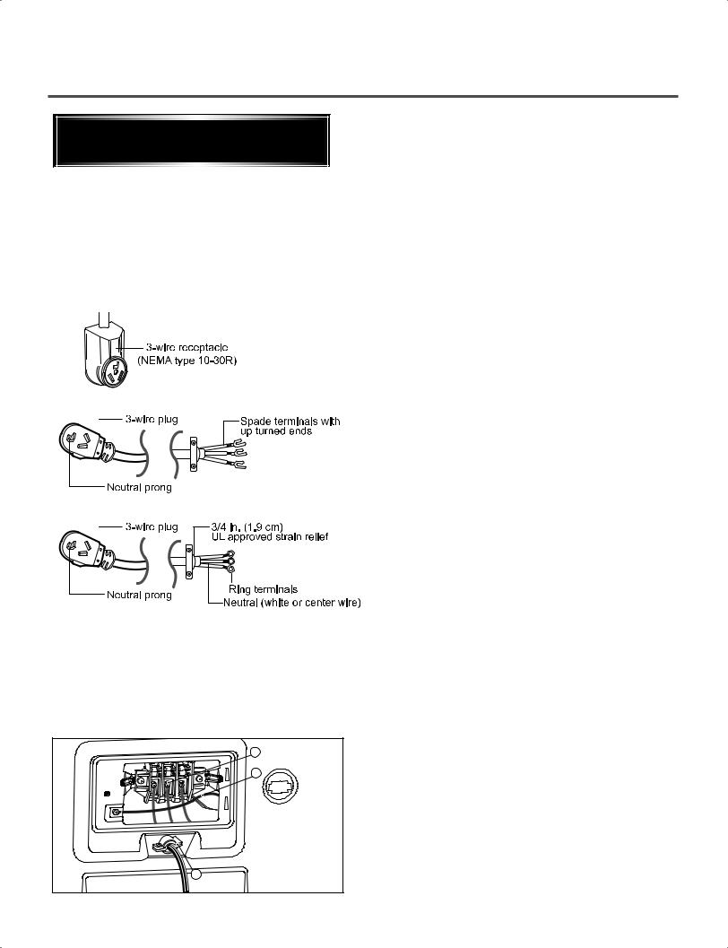
Option 2: 3-Wire Connection with a Power Supply Cord
lf your local codes or ordinances permit the connection of a frame-grounding conductor to the neutral wire, use these instructions. If your local codes or ordinances do not allow the connection of a frame-grounding conductor to the neutral wire, use the instructions under Section 3: Optional
3-wire connection.
1.Connect the neutral (white or center) wire (B) to the center, silver colored, screw (A) and tighten securely.
2.Connect the other two power cord wires (red and black) to the left and right terminal block screws and tighten securely.
3.Tighten the strain relief screws (C) securely.
A |
B |
C |
8
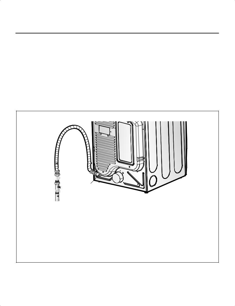
3-2. Connect Gas Supply Pipe (Gas Dryer ONLY)
For further assistance, refer to section on Gas Requirements.
1.Make certain your dryer is equipped for use with the type of gas in your laundry room. Dryer is equipped at the factory for natural gas with a 3/8” N.P.T. gas connection.
2.Remove the shipping cap from the gas connection at the rear of the dryer. Make sure you do not damage the pipe thread when removing the cap.
3.Connect to gas supply pipe using a new flexible stainless steel connector.
4.Tighten all connections securely. Turn on gas and check all pipe connections (internal & external) for gas leaks with a non-corrosive leak detection fluid.
5.For LP (Liquefied Petroleum) gas connection, refer to section on Gas Requirements.
 1
1


 2
2
5

 3
3  4
4
1 New Stainless Steel Flexible Connector |
4 |
Black Iron Pipe |
|
/ ” |
||||||
- |
|
Use only if allowed |
by local codes |
(Use |
|
Shorter than 20’ (6.1 m) - Use |
3 |
|||
|
|
|
|
|
|
|
|
|
|
8 |
2 |
Design A.G.A. Certified Connector) |
inlet |
|
pipe Longer than 20’ (6.1m) - Use |
||||||
1 |
/8” N.P.T. Pipe Plug |
( for checking |
|
1 |
/ ” pipe |
|
|
|||
|
gas pressure) |
|
|
5 |
|
|
2 |
|
|
|
|
|
|
3 |
/ ” N.P.T. Gas Connection |
|
|
||||
|
|
|
|
|
|
|
|
8 |
|
|
3 E q u i p m e n t S h u t - O f f V a l v e - I n s t a l l e d within 6’ (1.8 m) of dryer
9
4DRYER CYCLE PROCESS
|
|
|
|
|
|
Modifiers |
|
|
|
|
|
|
|
Type |
Cycle |
Fabrics Type |
Temperature |
Dry Level |
Time in |
More Time/ |
Wrinkle |
Damp Dry |
Static |
||||
|
|
|
|
|
|
|
Min. |
Less Time |
Guard |
Signal |
Shield |
||
|
|
|
|
|
|
|
|
|
|
|
|
|
|
|
|
|
|
Comforter,shirts,Trousers |
Mid High |
Off |
20 |
|
|
|
|
|
|
|
|
|
Steam Refresh |
|
|
|
|
|
|
|
|
|
|
|
|
|
1 - 5 garments (DO NOT |
Adjustable |
|
|
|
|
|
|
|
|
|
|
|
|
|
use for delicate fabrics) |
|
Adjustable |
|
|
|
|
|
|
|
|
|
|
|
|
|
|
|
|
|
|
|
|
|
|
|
|
Sanitize |
Comforter, Bedding, |
High |
Extra Dry |
70 |
|
|
|
|
|
|
|
|
|
Children's clothing, etc. |
|
|
|
|
|
|
|
|
|
|
|
|
|
|
|
|
|
|
|
|
|
|
|
|
|
|
|
|
|
|
|
|
|
|
|
|
|
|
|
|
|
Towels |
Denims, towels, heavy |
Normal |
Mid High |
55 |
|
|
|
|
|
|
Sensor |
|
cottons. |
Adjustable |
|
|
|
|
|
|
|
|
||
|
|
|
|
|
|
|
|
|
|||||
Dry* |
Heavy |
Jeans, heavyweight |
High |
Normal |
54 |
|
|
|
|
|
|
||
|
|
|
Duty |
items. |
|
Adjustable |
|
|
|
|
|
|
|
|
|
|
|
|
|
|
|
|
|
|
|
|
|
|
|
|
Casual |
Permanent press, |
Mid Low |
Normal |
36 |
|
|
|
|
|
|
|
|
|
|
|
|
|
|
|
|
|
|
||
|
|
|
synthetic items. |
|
Adjustable |
|
|
|
|
|
|
|
|
|
|
|
|
|
|
|
|
|
|
|
|
||
|
|
|
|
|
|
|
|
|
|
|
|
|
|
|
|
|
|
|
|
|
|
|
|
|
|
|
|
|
|
|
Bulky/Bedding |
Comforters, pillows,shirt. |
Medium |
Normal |
55 |
|
|
|
|
|
|
|
|
|
|
|
|
|
|
|
|
|
|
||
|
|
|
|
Adjustable |
|
|
|
|
|
|
|
||
|
|
|
|
|
|
|
|
|
|
|
|
|
|
|
|
|
|
|
|
|
|
|
|
|
|
|
|
|
|
|
Normal |
Work clothes, etc. |
Medium |
Normal |
41 |
|
|
|
|
|
|
|
|
|
|
|
|
|
|
|
|
|
|
||
|
|
|
|
Adjustable |
|
|
|
|
|
|
|
||
|
|
|
|
|
|
|
|
|
|
|
|
|
|
|
|
|
|
|
|
|
|
|
|
|
|
|
|
|
|
|
Workout Wear |
Workout wear |
Off |
Off |
27 |
|
|
|
|
|
|
|
|
|
|
|
|
|
|
|
|
|
|
||
|
|
|
|
|
|
|
|
|
|
|
|
|
|
|
|
|
|
Only Normal & |
High |
Normal |
30 |
|
|
|
|
|
|
|
|
|
Small Load |
Cotton/Towels fabric type |
|
|
|
|
|
|
|
|
|
|
|
|
|
Adjustable |
|
|
|
|
|
|
|
||
|
|
|
|
(Max 3lb) |
|
|
|
|
|
|
|
|
|
|
|
|
|
|
|
|
|
|
|
|
|
|
|
|
|
|
Delicates |
Lingerie, sheets, blouses. |
Mid Low |
Normal |
32 |
|
|
|
|
|
|
|
|
|
|
Adjustable |
|
|
|
|
|
|
|
||
|
|
|
|
|
|
|
|
|
|
|
|
|
|
|
|
|
|
|
|
|
|
|
|
|
|
|
|
|
|
|
Express Dry |
For small loads with short. |
High |
Off |
25 |
|
|
|
|
|
|
|
|
|
|
|
|
|
|
|
|
|
|
||
|
|
|
Adjustable |
|
Max 99 |
|
|
|
|
|
|
||
|
|
|
|
|
|
|
|
|
|
|
|
||
|
|
|
|
|
|
|
|
|
|
|
|
|
|
|
|
|
Touch Up |
For removing light |
Mid High |
Off |
20 |
|
|
|
|
|
|
Manual |
|
wrinkles. |
Adjustable |
|
Max 99 |
|
|
|
|
|
|
||
|
|
|
|
|
|
|
|
||||||
Dry** |
|
For items that require |
Off |
Off |
50 |
|
|
|
|
|
|
||
|
|
|
Air Dry |
heat-free drying such as |
Mid Low, Low |
|
Max 99 |
|
|
|
|
|
|
|
|
|
|
plastics or rubber. |
|
|
|
|
|
|
|
||
|
|
|
|
|
|
|
|
|
|
|
|
|
|
|
|
|
Rack Dry |
Wool sweaters, Silk, |
Off |
Off |
50 |
|
|
|
|
|
|
|
|
|
|
|
|
|
|
|
|
|
|
||
|
|
|
Lingerie. |
Mid Low, Low |
|
Max 99 |
|
|
|
|
|
|
|
|
|
|
|
|
|
|
|
|
|
|
|||
|
|
|
|
|
|
|
|
|
|
|
|
|
|
|
Motor |
Off Time: 6min |
|
On Time: 10sec |
|
Load |
|
|
|
|
|
|
Heater |
Temperature Control for each cycle |
|
|
*Sensor dry: Dry Level is set by users.
**Manual dry: Temperature control is set by users. Default settings can be adjusted by users.
10
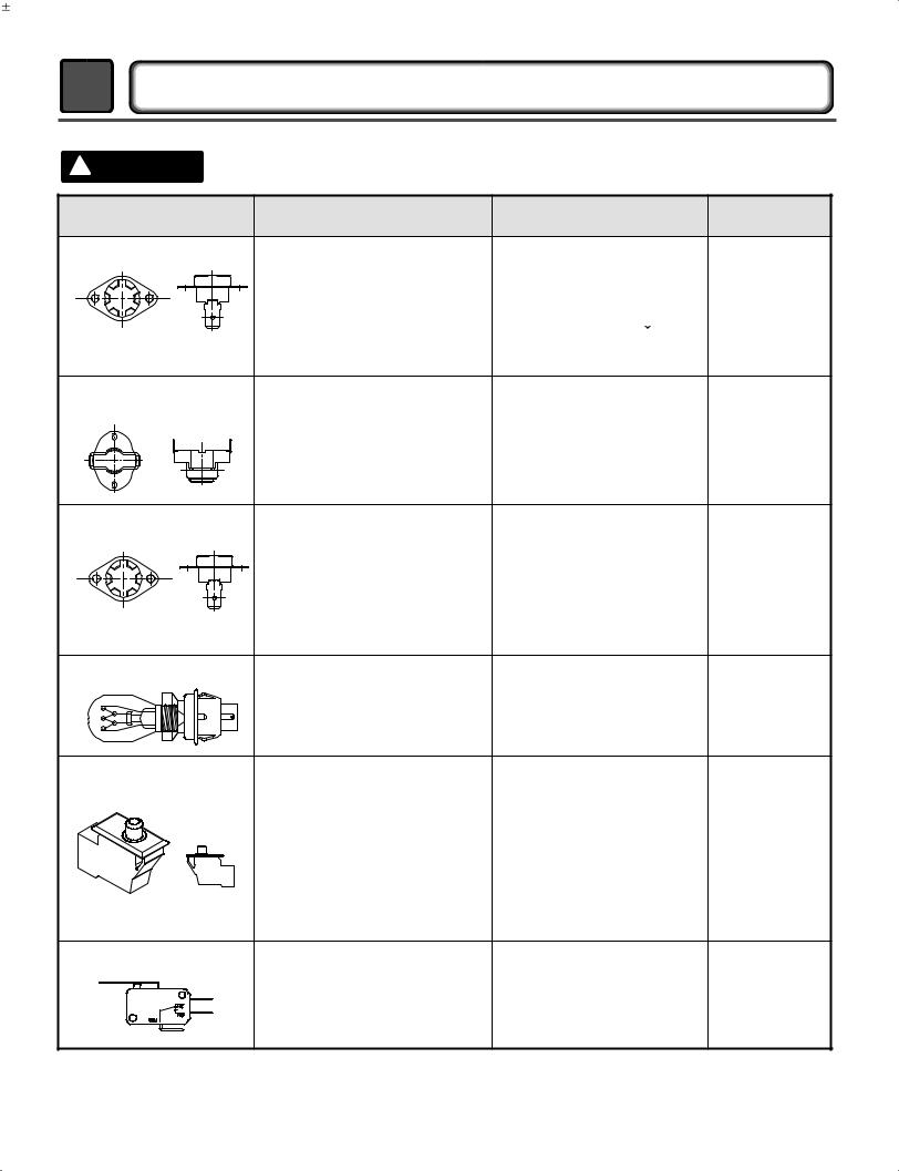
5 |
COMPONENT TESTING INFORMATION |
|||||
! |
CAUTION |
When checking the Component, be sure to turn the power off, and do voltage discharge sufficiently. |
||||
|
Component |
|
Test Procedure |
Check result |
Remark |
|
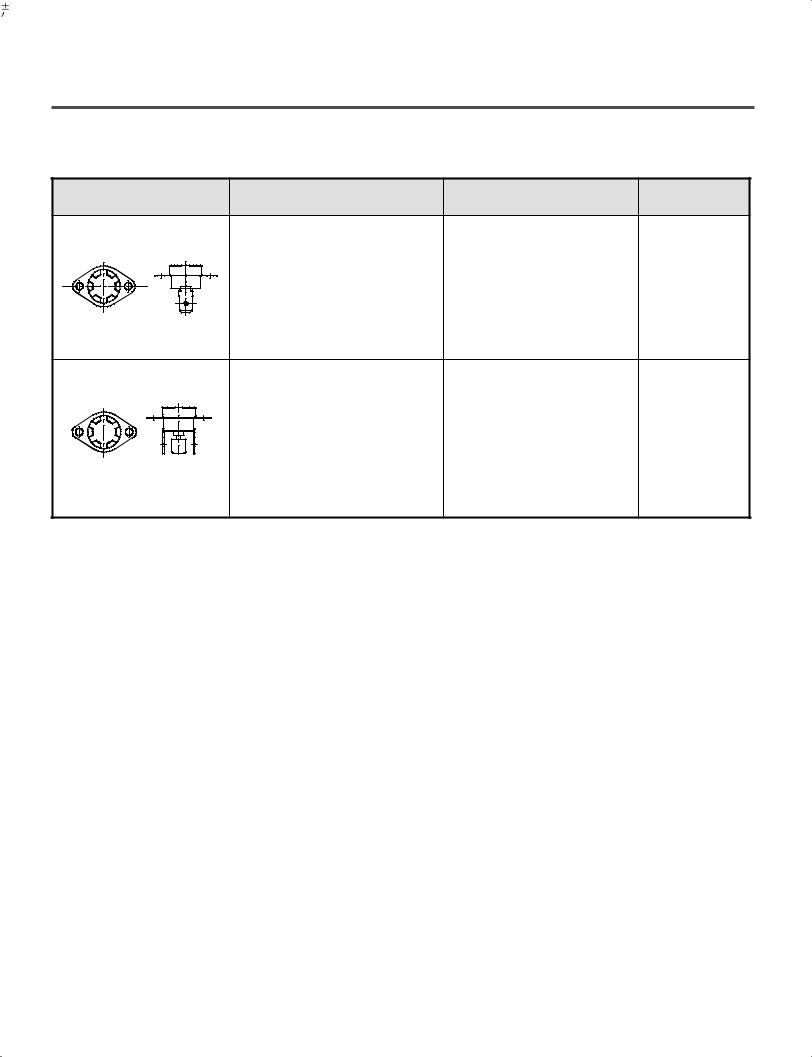
1. Thermal cut off |
Measure resistance of terminal |
If thermal fuse is open must |
• Heater case- |
|||
|
|
to terminal |
|
be replace |
Safety |
|
|
|
Open at 266 |
12°F |
Resistance value |
• Electric type |
|
|
|
(130 |
7°C) |
|
Continuity (250°F ) < 1Ω |
|
|
|
Auto reset 31°F (-1°C) |
|
|||
• Check Top Marking: |
|
|
||||
Same shape as Outlet Thermostat. |
|
|
||||
N130 |
|
|
||||
|
|
|
|
|
||
2.Hi limit Thermostat |
Measure resistance of terminal |
|
• Heater case - |
|||
(Auto reset) |
to terminal |
|
|
Hi limit |
||
|
|
Open at 257 |
9°F |
Resistance value |
• Electric type |
|
|
|
(125 |
5°C) |
|
|
|
|
|
Close at 221 |
9°F |
Resistance value < 5Ω |
|
|
|
|
(105 |
5°C) |
|
|
|
3.Outlet Thermostat |
Measure resistance of terminal |
|
• Blow housing - |
|||
( Auto reset) |
to terminal |
|
|
Safety |
||
|
|
Open at 185 |
9°F |
Resistance value |
• Electric type |
|
|
|
(85 |
5°C) |
|
|
|
|
|
Close at 149 |
9°F |
Resistance value < 5Ω |
|
|
• Check Top Marking: |
(65 |
5°C) |
|
|
|
|
|
|
|
|
|
||
N85 |
Same shape as Thermal cut off. |
|
|
|||
4. Lamp holder |
Measure resistance of terminal |
Resistance value: |
|
|||
|
|
to terminal |
|
80Ω ~ 100Ω |
|
|
5. Door switch |
Measure resistance of the |
|
The state that |
|
following terminal |
|
knob is |
|
1) Door switch knob: open |
|
pressed is |
|
|
opposite to |
|
|
Terminal: COM - NC(1-3) |
Resistance value < 1Ω |
|
|
open |
||
|
Terminal: COM - NC (1-2) |
Resistance value |
|
|
condition. |
||
|
2) Door switch push: push |
|
|
|
|
|
|
|
Terminal: COM - NC (1-3) |
Resistance value |
|
|
Terminal: COM - NC (1-2) |
Resistance value < 1Ω |
|
6. Idler switch |
Measure resistance of the |
1. lever open |
|
|
following terminal: |
Resistance value < 1Ω |
|
|
COM - NC |
|
|
|
2. Lever push (close) |
|
|
|
|
|
|
|
|
Resistance value |
|
11
5
Component |
Test Procedure |
Check result |
Remark |
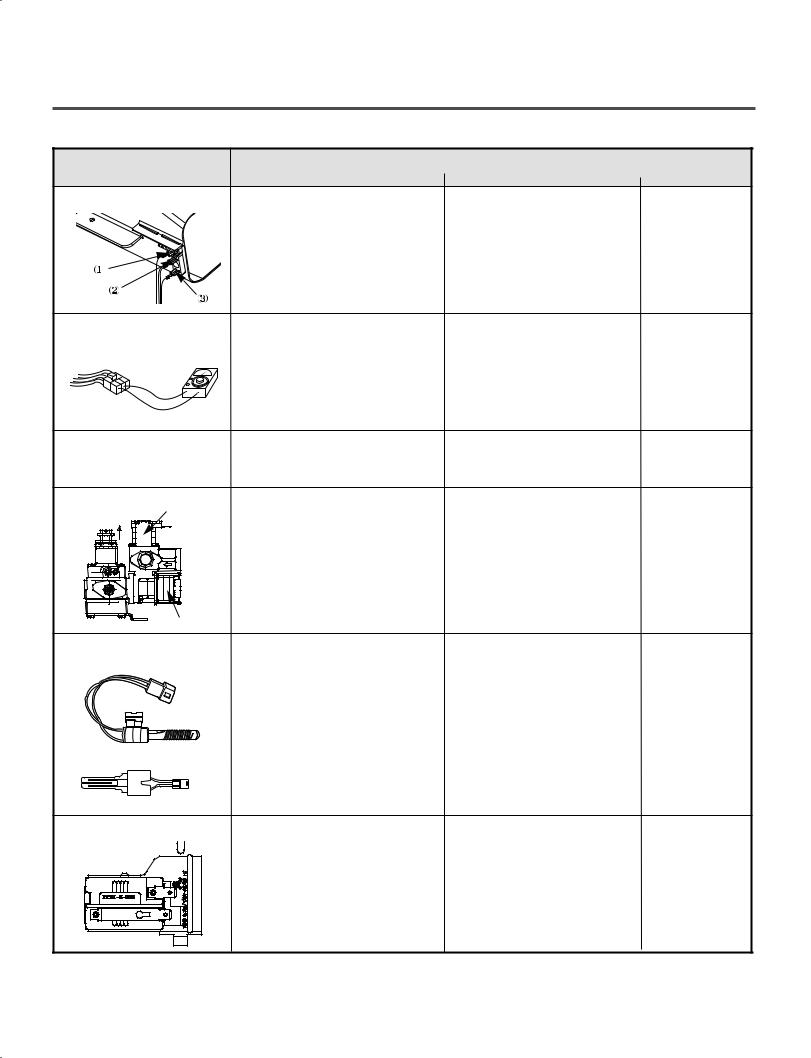
7. Heater |
Measure resistance of the |
|
• Electric type |
|
following terminal |
|
|
|
Terminal: 1 (COM) - 2 |
Resistance value: 10Ω |
|
|
Terminal: 1 (COM) - 3 |
Resistance value: 10Ω |
|
|
Terminal: 2 - 3 |
Resistance value: 20Ω |
|
8. Thermistor |
Measure resistance of terminal |
Resistance value: 10Ω |
• Heater case |
|
to terminal |
|
Hi limit |
|
Temperature condition: |
|
• Electric type |
|
58°F ~ (10~40°C) |
|
|
|
58°F ~ 104°F (10~40°C) |
|
|
9. Motor |
|
|
• See Page 15 |
10. Gas valve |
Measure resistance of the |
Resistance value2.3k~2.7kΩ |
• Gas type |
valve 1 |
following terminal |
||
|
Resistance value2.3k~2.7kΩ |
|
|
|
Valve 1 terminal |
|
|
|
Valve 2 terminal |
|
|
valve 2 |
11. Igniter |
Measure resistance from |
Resistance value |
• Gas type |
5318EL3001 |
terminal to terminal. |
100~800 Ω |
|
|
|
(for 5318EL3001) |
|
|
|
40-150 Ω |
|
|
|
(for MEQ1841001) |
|
MEQ61841001 |
|
|
|
12. Frame Detect |
Measure resistance of termina |
|
• Gas type |
|
to terminal |
|
|
|
Open at 370°F (Maximum) |
Resistance value |
|
|
Close at 320°F |
Resistance value < 1Ω |
|
12
Component |
Test Procedure |
|
Check result |
Remark |
|
13. Outlet Thermostat |
Measure resistance of terminal |
|
• Gas type |
||
(Auto reset) |
to terminal |
|
|
|
• Gas funnel |
|
Open at 203 |
7°F (95 |
5°C |
Resistance value |
|
|
Close at 159 |
9°F (70 |
5°C) |
Continuity < 1Ω |
|
•Check Top Marking: N95
14. Outlet Thermostatt |
Measure resistance of terminal |
If thermal fuse is open must |
• Gas type |
(Manual reset) |
to terminal |
be replaced |
• Gas funnel |
|
Open at 212 12°F |
Resistance value |
|
|
(100 7°C) |
|
|
|
Manual reset |
Continuity < 1Ω |
|
•Check Top Marking: N100
13
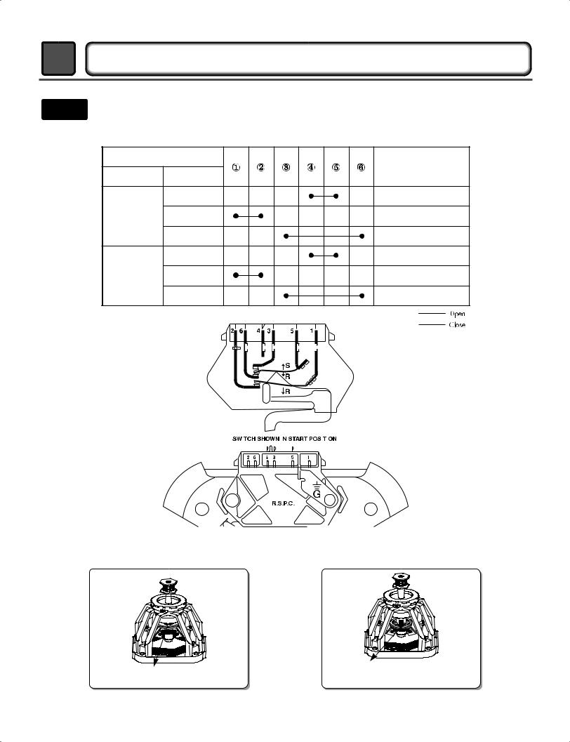
6MOTOR DIAGRAM AND SCHEMATIC
NOTE When checking Component, be sure to turn Power off, then do voltage discharge sufficiently.
■Contact On / Off by Centrifugal Switch
Terminal No |
Remark |
||
Mode |
Resistance |
||
|
|||
|
2 ~ 3Ω |
Motor |
|
Motor |
|
Heater (Electric Models) |
|
STOP |
|
||
|
|
||
|
|
Gas Valve (Gas Models) |
|
|
3 ~ 5Ω |
Motor |
|
Motor |
< 1Ω |
Heater (Electric Models) |
|
RUN |
|||
|
|
||
|
< 1Ω |
Gas Valve (Gas Models) |
|
|
|
|
|
|
|
|
|
|
|
|
|
|
|
|
|
|
|
|
|
|
|
|
|
|
|
|
|
|
|
|
|
|
|
|
|
|
|
|
|
|
|
|
|
|
|
|
|
|
|
|
|
|
|
|
|
|
|
|
|
|
|
|
|
|
|
|
|
|
|
|
|
|
|
|
|
|
|
|
|
|
|
|
|
|
|
|
|
|
|
|
|
|
|
|
|
|
|
|
|
|
|
|
|
|
|
|
■.RUN MODE |
||||
|
|
|
|
|
|
|
|
|
|
|
|
|
|
|
|
|
|
|
|
|
|
|
|||||
|
|
|
|
|
|
|
|
|
|
|
|
|
|
|
|
|
|
|
|
|
|
|
|||||
■ STOP MODE |
|
|
|
|
|
|
|
|
|
|
|
|
|
|
|
|
|
|
|
||||||||
(When Motor does not operate) |
|
|
|
|
|
|
|
|
|
|
|
|
|
|
|
|
|
|
|
|
|
|
|
(Motor operates) |
|||
Centrifugal switch |
Centrifugal switch |
|
(Pull Drive forward) |
||
|
14
 Loading...