


79090102207
Kenmore 79090102207, 79090153408, 79090152307, 79090152308, 79090102206 Installation Guide
...
United States
INSTALLATION AND SERVICE MUST BE PERFORMED BYA QUALIFIED INSTALLER.
IMPORTANT: SAVE FOR LOCAL ELECTRICAL INSPECTOR'S USE.
READ AND SAVE THESE INSTRUCTIONS FOR FUTURE REFERENCE.
pr_ FOR YOUR SAFETY: Do not store or use gasoline or other
flammable vapors and liquids in the vicinity of this or any other appliance.
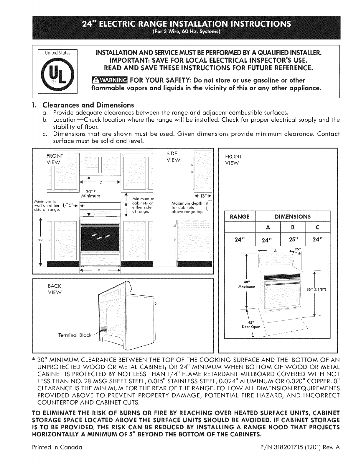
le Clearances and Dimensions
a. Provide adequate clearances between the range and adjacent combustible surfaces.
b. Location--Check location where the range will be installed. Check for proper electrical supply and the
stability of floor.
c. Dimensions that are shown must be used. Given dimensions provide minimum clearance. Contact
surface must be solid and level.
FRONT ................. ...... ........
Minimum to
Minimum
wall on either 1/16"_
side of range. _ _r of range.
36" _
I1!
T Minimum to
cabinets
18"
either side
B m._
BACK
VIEW
Terminal Block
SIDE
VIEW
J_- 13"-_J
on
for cabinets
Maximum depth _
above range top.
FRONT
VIEW
RANGE
DIMENSIONS
A B
24" 24"
Maximum
Door Open \
24" 25"
48"
45"
C
36" _+ 1/8")
\
30" MINIMUM CLEARANCE BETWEEN THE TOP OF THE COOKING SURFACE AND THE BOTTOM OF AN
UNPROTECTED WOOD OR METAL CABINET; OR 24" MINIMUM WHEN BOTTOM OF WOOD OR METAL
CABINET iS PROTECTED BY NOT LESS THAN I/4" FLAME RETARDANT MiLLBOARD COVERED WiTH NOT
LESSTHAN NO. 28 MSG SHEET STEEL, 0.015" STAINLESS STEEL, 0.024" ALUMINUM OR 0.020" COPPER. 0"
CLEARANCE iS THE MiNiMUM FOR THE REAR OF THE RANGE. FOLLOW ALL DiMENSiON REQUIREMENTS
PROVIDED ABOVE TO PREVENT PROPERTY DAMAGE, POTENTIAL FiRE HAZARD, AND iNCORRECT
COUNTERTOP AND CABINET CUTS.
TO ELIMINATE THE RISK OF BURNS OR FIRE BY REACHING OVER HEATED SURFACE UNITS, CABINET
STORAGE SPACE LOCATED ABOVE THE SURFACE UNITS SHOULD BE AVOIDED. IF CABINET STORAGE
IS TO BE PROVIDED, THE RISK CAN BE REDUCED BY INSTALLING A RANGE HOOD THAT PROJECTS
HORIZONTALLY A MINIMUM OF 5" BEYOND THE BOTTOM OF THE CABINETS.
Printed in Canada P/N 318201715 (1201) Rev. A

2. Install Anti-Tip Bracket(s). (See instructions
an page 4.)
3. Serial Plate Information
The serial plate is located on the frame and is
visible when the drawer is opened. See the serial
plate for the following information:
A. Model, lot and seriat number of range.
B. Kilowatt rating (power requirements).
C. Voltage ratings.
Serial plate location
4. Electrical Connection Requiremenfs
This appliance must be properly installed and
grounded by a qualified technician in accordance
with the National Electrical Code ANSI/NFPA
No. 70--latest edition--and local electrical code
requirements.
This appliance may be connected by means of
permanent "Hard Wiring" or "Power Supply Cord
Kit."
When hard wiring, do not leave excess wire in
range compartment. Excess wire in the range
compartment may not allow the access cover to
be replaced properly, and could create a potential
electrical hazard if wires become pinched. Connect
only as instructed under "WIRING INSTRUCTIONS"
in sections 6 and 7. When using flexible conduit
or range cable, use flex connector or range cable
strain relief.
NOTE: Only use copper wire in connection to
terminal block.
l
4B. Models Requiring Power Supply Cord Kit
RiSK OF FiRE OR ELECTRICAL
SHOCK MAY OCCUR iF AN iNCORRECT SiZE
RANGE CORD KiT IS USED, THE INSTALLATION
iNSTRUCTiONS ARE NOT FOLLOWED OR STRAIN
RELIEF BRACKET iS DISCARDED.
This appliance may be connected by means of a
power supply cord. Only a power supply cord kit
rated at 40 amperes, 125/250 volts minimum, and
marked for use with ranges shall be used. Cord
must have three (3) conductors. Terminals on end
of wires must be either closed loop or open-end
spade lugs with upturned ends. Cord must have
strain relief clamp.
NOTE: MOBILE HOME iNSTALLATiON OR
AREAS WHERE LOCAL CODES DO NOT PERMIT
GROUNDING THROUGH NEUTRAL, A FOUR (4)
CONDUCTOR POWER CORD MUST BE USED.
A 1-3/8" knock-out hole is provided at the bottom
of the range terminal box for connecting the power
supply cord kit to the range terminal block (see
Figures 2 and 3).
5. Permanent Hard Wiring (3 or 4 Wires)
insert the residence 3-wire power supply cable
through the 1-1/8" hole at the bottom of the range
terminal box (see Figure 2). For mobile home
application or where connections with a 3-wire
power supply cabte is not allowed, use a 4-wire
power supply cable (for connections, see Figure 3).
Use a U.L. approved strain relief clamp to secure
the cable to the terminal box.
6. Wirinc Instructions - 3-Wire Supply Cable
ELECTRICAL GROUND IS REQUIRED
ON THIS APPLIANCE.
This appliance is manufactured with the neutral
terminal connected to the frame. If local codes
permit connection of the frame grounding
conductor to the neutral wire of the copper power
supply cord:
(The 3-conductor cord or cable must be replaced
with a 4-conductor cord or cable where grounding
through the neutral conductor is prohibited in new
installations, mobile homes, recreational vehicles
or in other areas where local codes do not permit
neutral grounding.)
U.S. STYLE
Figure 1 - 3=Wire Cord Kit
From
range
........... Range
Some _rl _]
Models [[_
silver !/\\
colored.__ _\
..... A,, Terrain a
L_ne 2 ....
; I Neutral ....
..<_| (whi=eor
BOX
_{_ center)
iS :
UneIJ
Groood-/
link / \'
Ground ==_ "_
screw
Strain -_q
...... relief
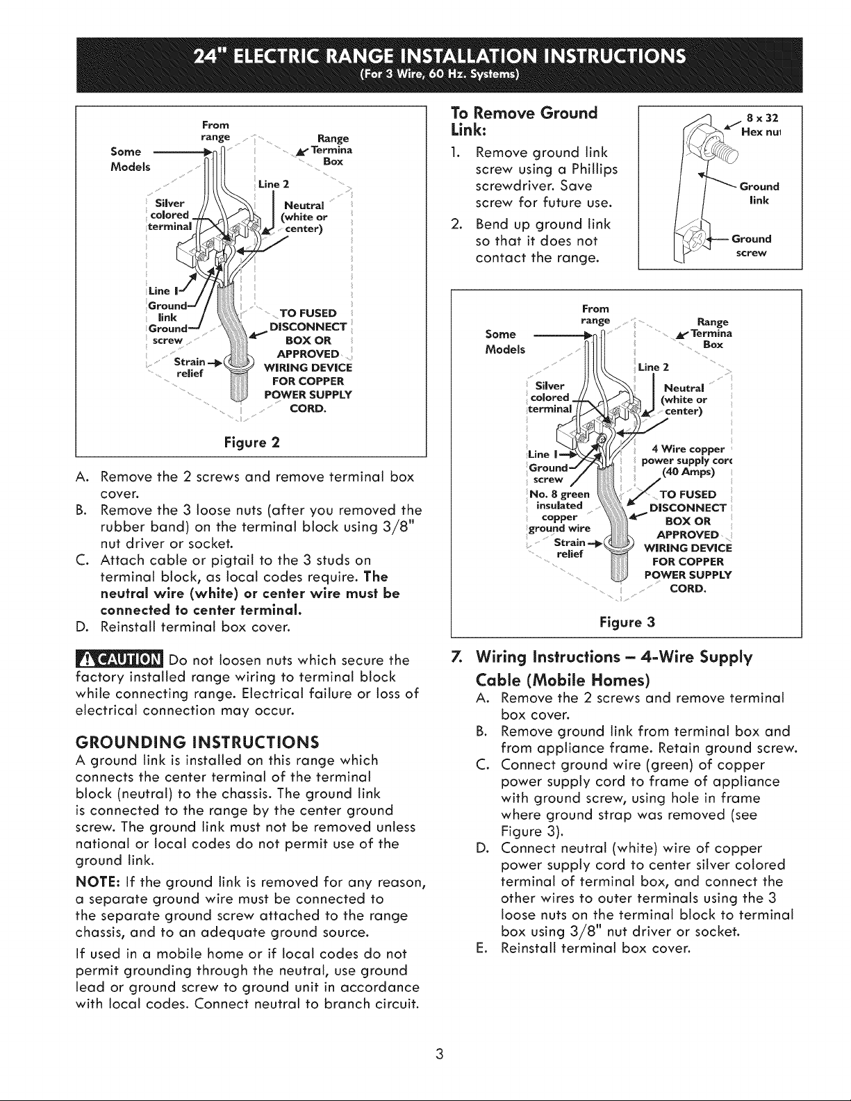
A. Remove the 2 screws and remove terminal box
cover.
B. Remove the 3 loose nuts (after you removed the
rubber band) on the terminal block using 3/8"
nut driver or socket.
C. Attach cable or pigtail to the 3 studs on
terminal block, as local codes require. The
neutral wire (white) or center wire must be
connected to center termlnal.
D. Reinstall terminal box cover.
;_}" BoxoR
Figure 2
TOFUSED
0,SCONNECT
APPROVED.......
WIRING DEVICE
FOR COPPER
POWER SUPPLY
..... CORD.
To Remove Ground
Link:
Remove ground link
screw using a Phillips
screwdriver. Save
screw for future use.
2. Bend up ground link
so that it does not
contact the range.
From
range .... Range
; Silver J Neutral .......
colored. _| (whiteor
terminal _center)
il
Une 4Wirecopper:
screw /TNo. 8 green O FUSED
insuJated
copper _i1_'" BOX OR
ground wire
Strain-=_relief i_ WIRING DEVICE
...... " POWER SUPPLY
...... _ Termina
_Line 2 ...........
power supply car(
DISCONNECT
APPROVED
FOR COPPER
:; CORD.
Figure 3
8x32
nUl
Ground
link
Ground
screw
...... Box
(40 Amps)
Do not loosen nuts which secure the
factory installed range wiring to terminal block
while connecting range. Electrical failure or loss of
electrical connection may occur.
GROUNDING INSTRUCTIONS
A ground link is installed on this range which
connects the center terminat of the terminal
block (neutral) to the chassis. The ground link
is connected to the range by the center ground
screw. The ground link must not be removed unless
national or local codes do not permit use of the
ground link.
NOTE: If the ground link is removed for any reason,
a separate ground wire must be connected to
the separate ground screw attached to the range
chassis, and to an adequate ground source.
If used in a mobile home or if local codes do not
permit grounding through the neutral, use ground
lead or ground screw to ground unit in accordance
with local codes. Connect neutral to branch circuit.
Z
Wiring Instructions - 4-Wire Supply
Cable (Mobile Homes)
A. Remove the 2 screws and remove terminal
box cover.
B. Remove ground link from terminal box and
from appliance frame. Retain ground screw.
C. Connect ground wire (green) of copper
power supply cord to frame of appliance
with ground screw, using hole in frame
where ground strap was removed (see
Figure 3).
D. Connect neutral (white) wire of copper
power supply cord to center silver cotored
terminal of terminal box, and connect the
other wires to outer terminals using the 3
loose nuts on the terminal btock to terminal
box using 3/8" nut driver or socket.
E. Reinstall terminal box cover.
8. Anti-tip Bracket Installation Instructions
important Safety Warning
To reduce the risk of tipping of the range, the range
must be secured to the floor by the properly installed
anti-tip bracket and screws packed with the range.
Failure to install the anti-tip bracket will allow the
range to tip over if excessive weight is placed on an
open door or if child climbs upon it. Serious injury
might result from spilled hot liquids or from the range
itself.
if range is ever moved to a different location, the
anti-tip brackets must also be moved and installed
with the range.
Instructions are provided for installation in wood
or cement floor. When fastening to floor, be sure
that screws do not penetrate electrical wiring or
plumbing.
Tip Over Hazard
* A child or adult can tip the range
and be killed.
* Verify the anti-tip device has
been installed to floor or wall.
* Ensure the anti-tip device is re-engaged to floor
or wall when the range is moved.
Do not operate the range without the anti-tip
device in place and engaged.
Failure to follow these instructions can result in
death or serious burns to children and adults.
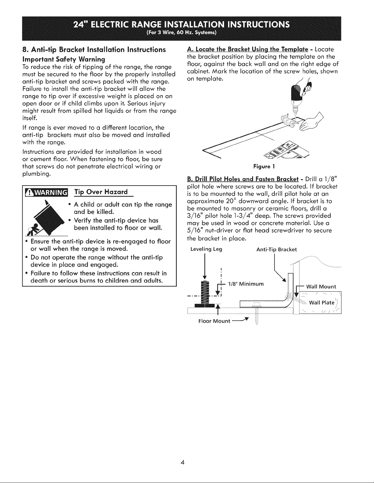
A. Lacate the Bracket Using the Template - Locate
the bracket position by placing the template on the
floor, against the back wall and on the right edge of
cabinet. Mark the location of the screw holes, shown
on template.
Figure |
B. Drlll Pilot Hales and Fasten Bracket - Drill a 1/8"
pilot hole where screws are to be located. If bracket
is to be mounted to the wall, drill pilot hole at an
approximate 20 ° downward angle. If bracket is to
be mounted to masonry or ceramic floors, drill a
3/16" pilot hole 1-3/4" deep. The screws provided
may be used in wood or concrete material. Use a
5/16" nut-driver or flat head screwdriver to secure
the bracket in place.
Leveling Leg Anti-Tip Bracket
1/8" M,n,mum Wallr Mount I
all :ia;:/f
Floor Mount _ ,_
V
4
 Loading...