


79075993100
Kenmore 79075993100, 79075993101, 79075993102, 79075754100, 79075751100 Installation Guide
...
INSTALLATION AND SERVICE MUST BE PERFORMED BY A QUALIFIED INSTALLER.
IMPORTANT: SAVE FOR LOCAL ELECTRICAL INSPECTOR'S USE.
READ AND SAVE THESE INSTRUCTIONS FOR FUTURE REFERENCE.
If the information in this manual is not followed I
exactly, a fire or explosion may result causing property
damage, personal injury or death.
FOR YOUR SAFETY:
Do not store or use gasoline or other flammable vapors
and liquids in the vicinity of this or any other appliance.
A
w --
-- WHAT TO DO IF YOU SMELL GAS:
• Do not try to light any appliance.
• Do not touch any electrical switch; do not use any phone
in your building.
• Immediately call your gas supplier from a neighbor's
phone. Follow the gas supplier's instructions.
• If you cannot reach your gas supplier, call the fire
v
V
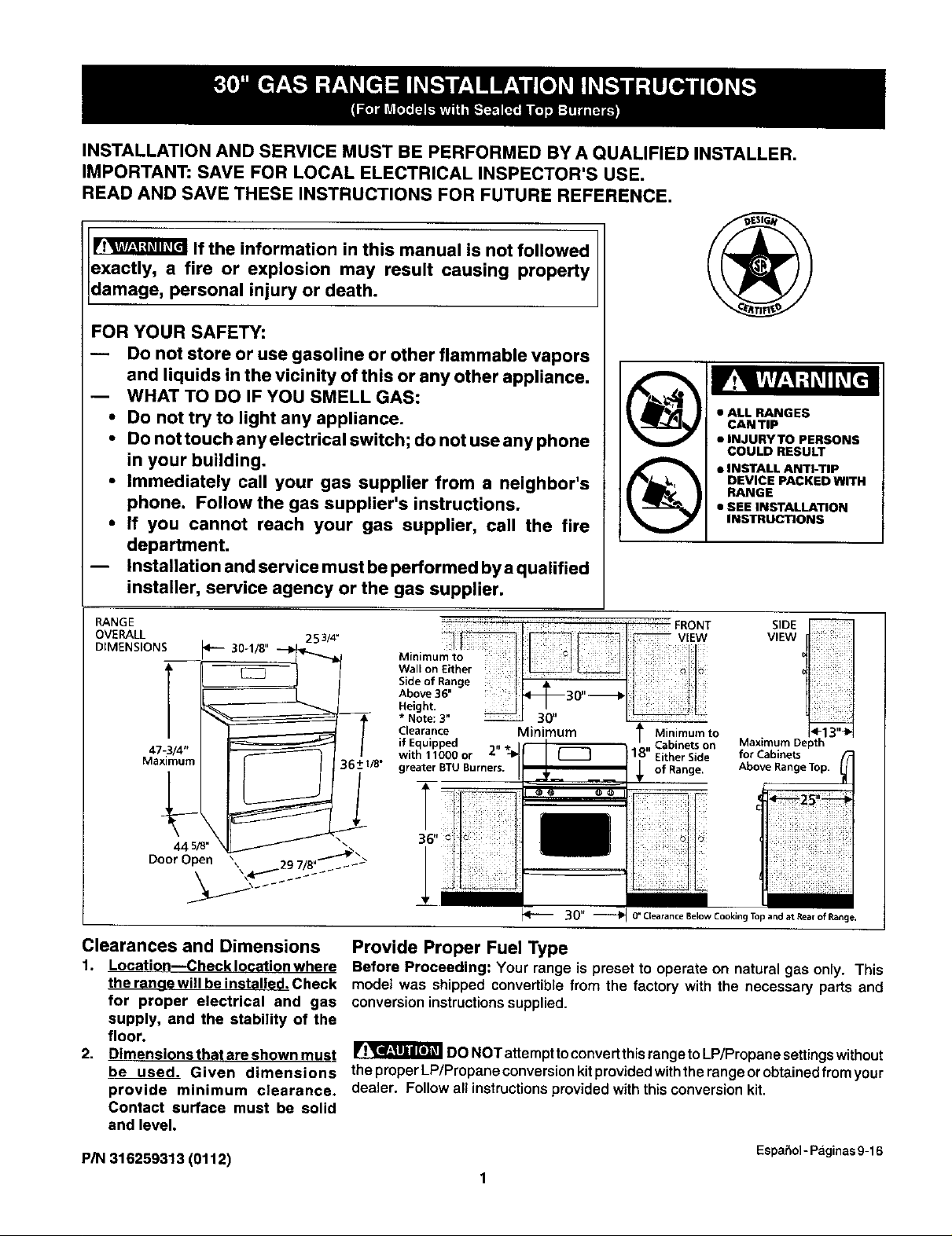
• ALL RANGES
CAN TIP
• |NJURYTO PERSONS
COULD RESULT
• INSTALL ANTI-TIP
DEVICE PACKED WITH
RANGE
• SEE INSTALLATION
INSTRUCTIONS
department.
-- Installation and service must be performed by a qualified
installer, service agency or the gas supplier.
)
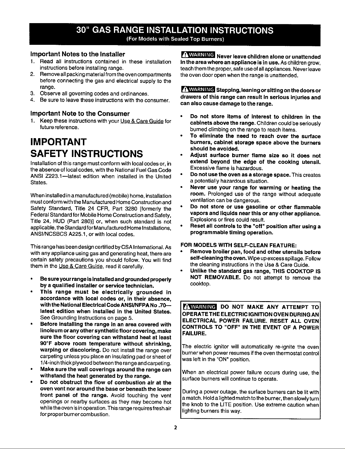
RANGE
OVERALL 253/4"
DIMENSIONS <-- 30-1/8" -_......_._
* Note: 3"
Clearance Minimum Minimum to
47-3/4" _ !
Maximum 36_+i/8.
Door Open 29 7/8"""_ 2>
Clearances and Dimensions
1.
Location--Checklocationwhere Before Proceeding: Your range is preset to operate on natural gas only. This
the rn_Dg__willbein tI_.Check model was shipped convertible from the factory with the necessary parts and
if Equipped . Cabinets on Maximum Depth
with 11000 or I Either Side for Cabinets
greater BTU Burners. of Range. Above Range Top.
0" Clearance Below Cooking Top and at Rear of Range.
Provide Proper Fuel Type
SIDE
VIEW
for proper electrical and gas conversioninstructionssupplied.
supply, and the stability of the
floor.
2.
Dimensions that areshown must IIr_ DONOT attempttoconvertthisrange toLP/Propanesettingswithout
be used. Given dimensions theproperLP/Propaneconversionkitprovidedwiththerangeorobtainedfmmyour
provide minimum clearance, dealer. Follow all instructionsprovidedwiththis conversionkit.
Contact surface must be solid
and level.
P/N 316259313 (0112)
EspaSol - Paginas 9-16
1
Important Notes to the Installer
1. Read all instructionscontained in these installation
instructionsbefore installingrange.
2. Removeallpackingmaterial from theovencompartments
before connectingthe gas and electrical supplyto the
range.
3. Observe all governing codes and ordinances.
4. Be sure toleave these instructionswiththe consumer.
Important Note to the Consumer
1, Keep these instructionswithyourUse & Care Guide for
future reference.
IMPORTANT
SAFETY INSTRUCTIONS
Installationofthisrangemustconformwithlocal codesor,in
theabsence of localcodes, withtheNationalFuelGas Code
ANSI Z223.1--1atest edition when installed in the United
States.
Wheninstalled ina manufactured (mobile)home, installation
must conform with the Manufactured Home Construction and
Safety Standard, Title 24 CFR, Part 3280 [formerly the
Federal Standard for Mobile Home Construction and Safety,
Title 24, HUD (Part 280)] or, when such standard is not
applicable, the Standard forManufactured Home Installations,
ANSI/NCSBCS A225.1, or with local codes.
Never leave children alone or unattended
in the area where an appliance is in use. Aschildrengrow,
teachthem the proper, safe useofall appliances.Neverleave
theoven dooropenwhenthe range is unattended.
Stepping, leaningor sitting onthe doors or
drawers of this range can result in serious injuries and
can also cause damage to the range.
• Do not store items of interest to children in the
cabinets above the range. Childrencouldbeseriously
burnedclimbingon the rangeto reach items.
• To eliminate the need to reach over the surface
burners, cabinet storage space above the burners
should be avoided.
Adjust surface burner flame size so it does not
extend beyond the edge of the cooking utensil.
Excessive flame ishazardous.
Do not use the oven as a storage space. Thiscreates
a potentiallyhazardoussituation.
• Never use your range for warming or heating the
room. Prolonged use of the range without adequate
ventilationcan be dangerous.
• Do not store or use gasoline or other flammable
vapors and liquids near this or any other appliance,
Explosionsor fires couldresult.
• Reset all controls to the "off" position after using a
programmable timing operation.
This range has been design certified byCSA International.As
withany applianceusinggas and generating heat,there are
certain safety precautions you shouldfollow. You willfind
them in the Use & Care Guide, read itcarefully.
• Besure your range isinstalled and grounded properly
by a qualified installer or service technician.
This range must be electrically grounded in
accordance with local codes or, in their absence,
with the National Electrical Code ANSI/NFPA No .70--
latest edition when installed in the United States.
See Grounding instructionson page 5.
Before installing the range in an area covered with
linoleum or any other synthetic floor covering, make
sure the floor covering can withstand heat at least
90°F above room temperature without shrinking,
warping or discoloring, Do not install the range over
carpetingunlessyou placean insulatingpad orsheetof
1/4-inchthickplywoodbetweenthe rangeandcarpeting.
• Make sure the wall coverings around the range can
withstand the heat generated by the range.
• Do not obstruct the flow of combustion air at the
oven vent nor around the base or beneath the lower
front panel of the range. Avoid touching the vent
openings or nearbysurfaces as they may become hot
whiletheovenis inoperation.Thisrangerequiresfresh air
forproperburnercombustion.
FOR MODELS WITH SELF-CLEAN FEATURE:
Remove broiler pan, food and other utensils before
self-cleaning the oven. Wipeupexcessspillage.Follow
the cleaning instructionsinthe Use & Care Guide.
• Unlike the standard gas range, THIS COOKTOP IS
NOT REMOVABLE. Do not attempt to remove the
cooktop.
DO NOT MAKE ANY ATTEMPT TO
OPERATETHE ELECTRIC IGNITION OVEN DURING AN
ELECTRICAL POWER FAILURE. RESET ALL OVEN
CONTROLS TO "OFF" IN THE EVENT OF A POWER
FAILURE.
The electric ignitor will automatically re-ignite the oven
burner when power resumes ifthe oven thermostat control
was left in the "ON" position.
When an electrical power failureoccurs during use, the
surface burners will continue to operate.
During a power outage, the surface burners can be lit with
a match. Hold a lightedmatchto the burner, then slowlyturn
the knob to the LITE position. Use extreme caution when
lighting burners this way.
Before Starting
Tools You Will Need
For leveling legs and Anti-Tip Bracket:
Adjustable wrench or channel lockpliers
5/16" Nutdriveror Fiat Head Screw Driver
ElectricDrill& 1/8"DiameterDrillBit(5/32" MasonryDrill
Bit if installinginconcrete)
For gas supply connection:
Pipe wrench _
For burner flame adjustment:
Phillipshead _ and
blade-type screwdrivers
For gas conversion (LP/Propane or Natural):
Open end wrench- 1/2"
Additional Materials You Will Need
Gas
line shut-offvalve
Pipe jointsealant that resistsactionof LP/Propane gas
A new flexible metal appliance conduit(1/2" NPT x 3/4"
or 1/2" I.D.) mustbe design certified byCSA International.
Because solid pipe restricts moving the range we
recommend using a new flexible conduit (4 to 5 foot
length) for each new installation and additional
reinstallations.
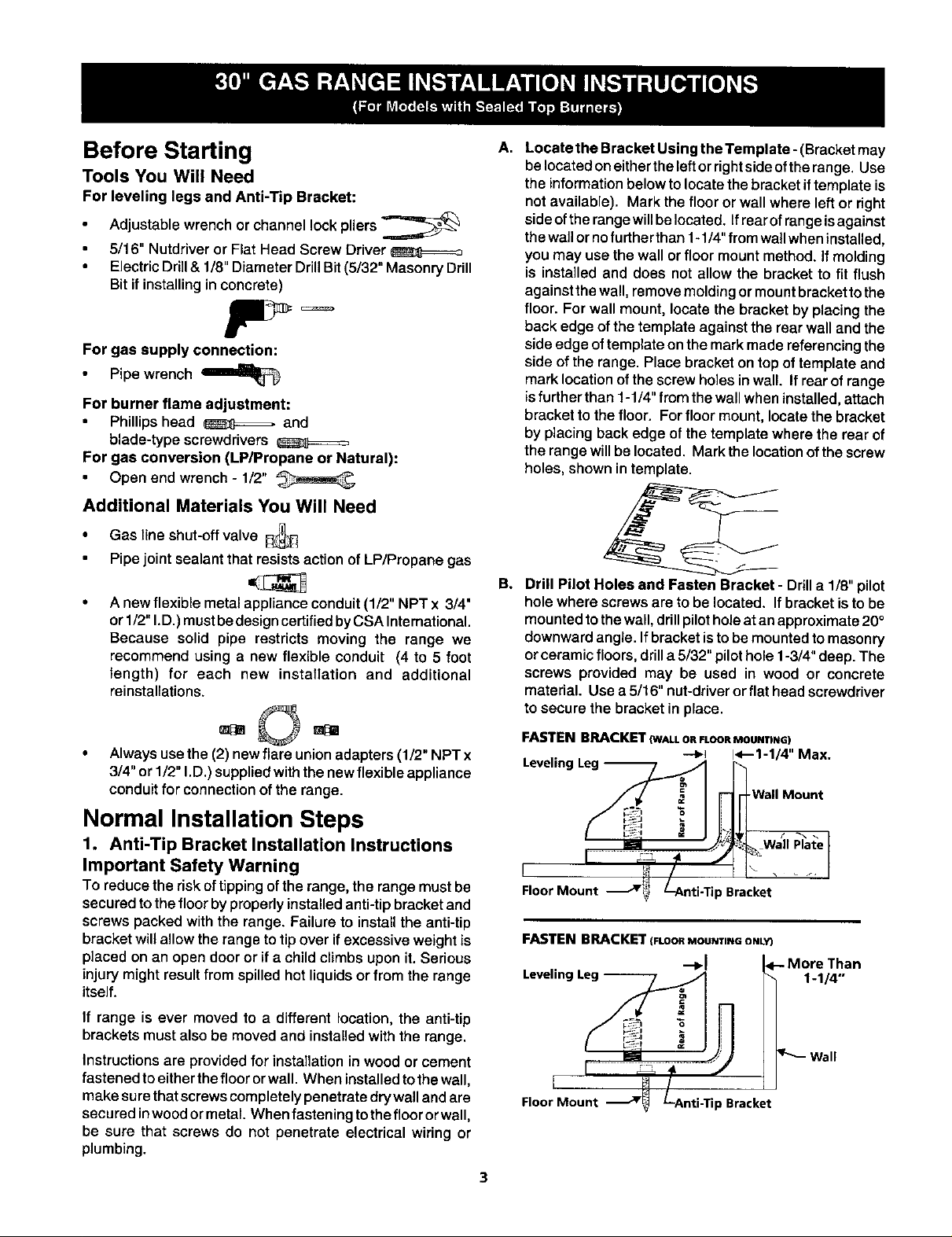
A.
Locate the Bracket Using the Template - (Bracket may
belocatedon eitherthe leftorrightsideofthe range. Use
the intormation below to locate the bracket if template is
not available), Mark the floor or wall where left or right
side ofthe range will belocated. Ifrear of range isagainst
the wa_or nofurther than 1-1/4" fromwa_{wheninstalled,
you may use the wall or floor mount method. If molding
is installed and does not allow the bracket to fit flush
against the wall, remove molding or mount bracket to the
floor. For wall mount, locate the bracket by placing the
back edge of the template against the rear wall and the
side edge oftemplate on the mark made referencing the
side of the range. Place bracket on top of template and
mark location of the screw holes in wall. If rear of range
isfurther than 1-1/4" from the wall when installed, attach
bracket to the floor. For floor mount, locate the bracket
by placing back edge of the template where the rear of
the range will be located. Mark the location of the screw
holes, shown in template.
Be
Drill Pilot Holes and Fasten Bracket - Ddll a 1/8" pilot
hole where screws are to be located. If bracket is to be
mounted to the wall, drillpilot hole at an approximate 20 °
downward angle. If bracket is to be mounted to masonry
or ceramic floors, drill a 5/32" pilot hole 1-3/4" deep. The
screws provided may be used in wood or concrete
material. Use a 5/16" nut-driver or flat head screwdriver
to secure the bracket in place.
Alwaysuse the (2) new flare union adapters (1/2" NPT x
3/4" or 1/2" I.D.) supplied with the new flexible appliance
conduit for connection of the range.
Normal Installation Steps
1. Anti-Tip Bracket Installation Instructions
Important Safety Warning
To reduce the risk oftippingofthe range, the rangemustbe
securedto the floorbyproperly installedanti-tipbracketand
screwspacked with the range, Failureto installthe anti-tip
bracketwillallow the range to tip over ifexcessive weight is
placed on an open dooror if a child climbsupon it.Serious
injury might resultfrom spilledhot liquidsor from the range
itself.
If range is ever moved to a different location, the anti-tip
brackets must also be moved and installed with the range.
Instructionsare provided for installation in woodor cement
fastened to eitherthe floor orwall. When installed to the wall,
make sure that screws completely penetrate dry wall and are
secu red inwood or metal. When fastening tothe floor or wall,
be sure that screws do not penetrate electrical wiring or
plumbing.
FASTENBRACKET_WALLOneLOORMOUNTING)
-'_1 1<--1-1/4" Max.
Levellng Leg _l _
Floor Mount J_ L-Anti-Tip Bracket
FASTEN BPJ_CKET(FLOORMOUNTINGONL_
•->1 Than
Levelinc 1-1/4"
Floor Mount ) Bracket
3
 Loading...