


Kenmore 1660 User Manual
Kenmore
INSTRUCTIONS
ZIG-ZAG SEWING MACHINE
MODEL 1357/1525/1660/1947
60278
■ A-fe
^USIÑG'THECONTROLS'■■■■■■ .-■■■■■ ■ '
',-V%3
.■í3»'
fkS-
J^-<VA\iviÄ4<^<Äi
m
§0ÍÍ
гЧ<Г<^
í«¿-:
>A^í^sí':r
‘S-SC.Ñé
" ' ' ' '
V,. |'>.''Г- ',1-5.-^' <r,
j'
ШкШ:
йÄ^.йЙЦ*^¡й^• {vSí^
....■•■ •- -'íSi
- ’ -,-,-------^---- l-.-v"'
4f,#JÍ ♦•* *.Мг«1 * * * m* • ♦ ♦ jí '« H * * t
-------------
iw Suttonnòl^OontìròI «.««»■.•«•»4t*«
jy|^jlb«K.r«.*«»«.« «^>»«« к» * »«-♦««««« •'*>»«
«4í'«»f « ![¥«• wM*
4\wC 1ÍW^4'¿*i 4 #;■ V • к * i • « * #* * ■: ¿ M» ♦^»•^**»•••*■*•••••11* él£jm ■ ' '
fiiTl
íTkA««* *.«;«;* ì*ù к Ш IklkliV iik V« * V« * « « м 30 * Зо •
. „ --•«¿•*4 « к «**♦/£'«*»• к к к к к* « « < «'*<*»<(jM к кЧ« k*«vO ' .
j|í:f 1 Ò '
“"'7 " ''г ' ’''
* ■^í' ' 4 yí' '" '
Fi¥‘
,-v - - .4 ■>'/,*', - . , r . ■'
''■ .л':^
Л1.Щ
^^j3?''^Sfc”-K ' 'v'' 'i., • " ‘ C^F^^НННННmGÍ ,Р*в6^ £3ÓÌQ6 "ÉlfltÍ ^ifÜUtuö •••ж V e • »• *i 1 • • e • n • ♦• e « » «»•■ * • к «^4','
kkkkk ':] ■%'.?■,ЛЛ Лi-'^IÍt^‘Ürí<Í0Mmí Cover Máteii
А' QfbH^^MnCiäii^idii »»k'ííkíiilí *»У»«*Гккк *•♦< 4 кав^«««>*кЖк**к«*к ;u4S,4?i
............. oSnfWFáélCóVérHát^....^
Parte List .i.
.....
.........í.......................................
.............
.....
......',
.........
.................47
..45';
48/ 49
1. KNOWING YOMB MACHIA
»
' -i:' r
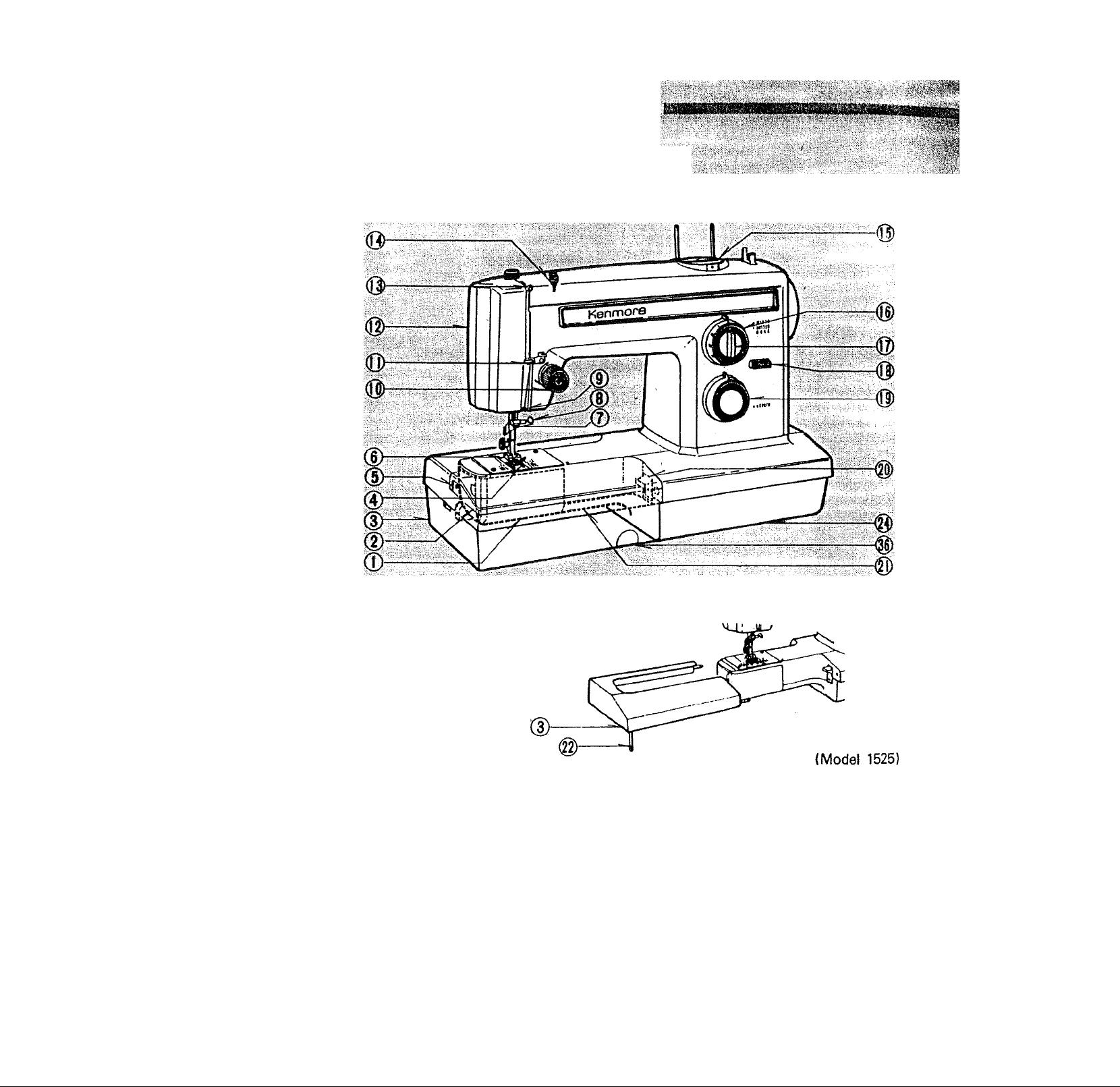
FRONT VIEW
1.
Shuttle cover
2.
Base front cover
3.
Base
4.
Zigzag stitch needle plate
5.
Front cover release button
6.
Presser foot
7.
Thread guide
8.
Needle clamp screw
9.
Thread guide
10.
Top thread tension control 20. Feed dog control
11.
Face cover thread guide 21. Free arm
12. Face cover plate
13. Take-up lever
14.
Upper thread guide
Special stitch dial
15.
16.
Stitch width control
17.
Special stitch modifier and
buttonhole control
Reverse stitch lever
18.
19.
Stitch length control
22. Support leg
' ' i f’iv 'V' >, , ■" . ,■:
' ' *
..............Iifiiiflir nnin;i.i'i 1^
iiagisrfai^^ v :;:aaw
>lli-
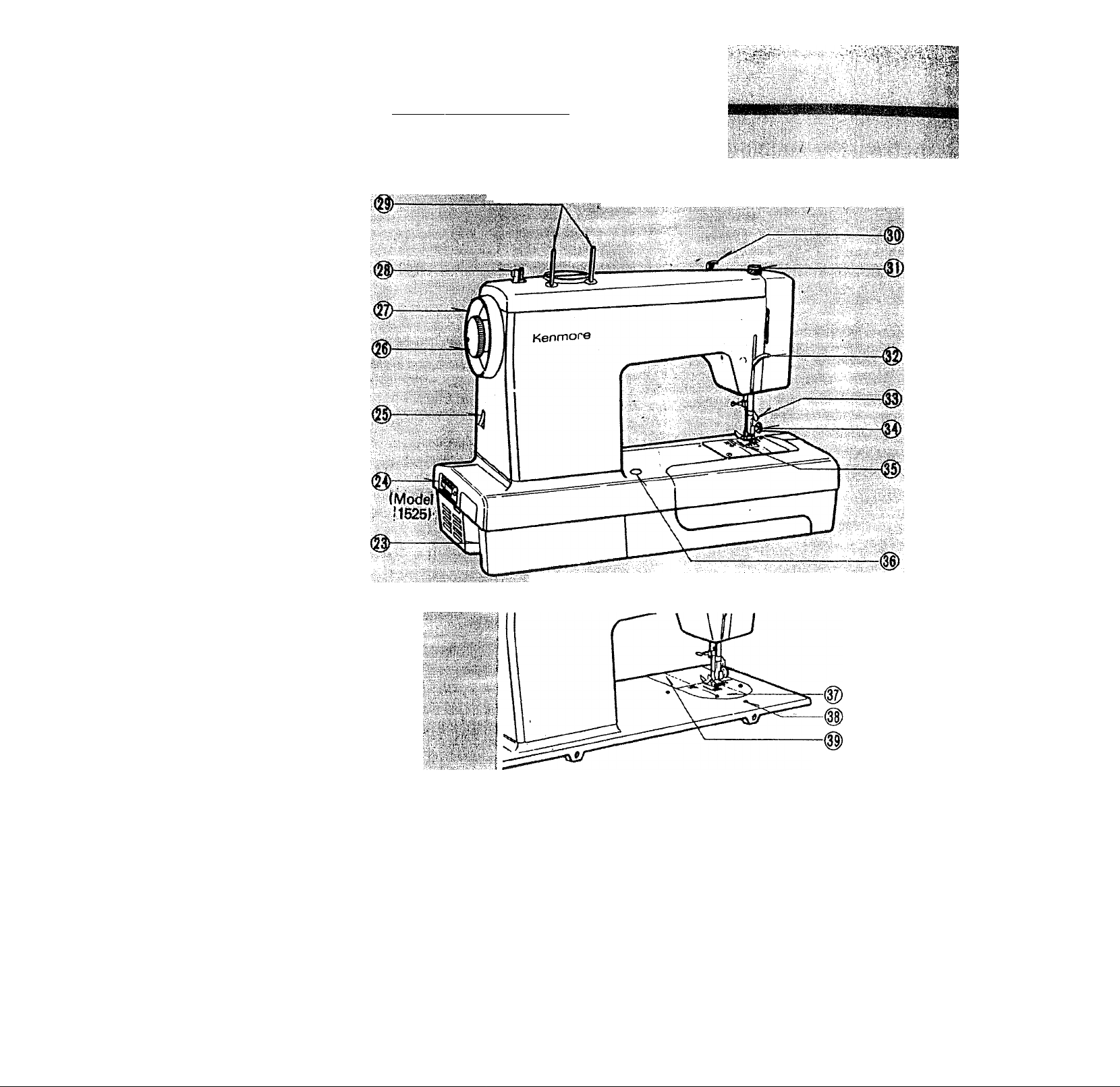
;iiACKVIEW
..........
■■'■■■""
iiiiail®
23. Electric cord receptacle
24. Nomenclature plate
25. Light and power switch
26. Clutch knob
27. Hand wheel
28. Bobbin winder
29. Spool pins
30. Bobbin winder tension disc
31. Pressure regulator
(Model 1660)
{Flat-bed type)
32. Presser foot lever
33. Thread cutter
34. Presser foot thumb screw
35. Feed dogs
36. Base release button
37. Needle plate
38. Guide pin hole
39. Hand hole cover plate
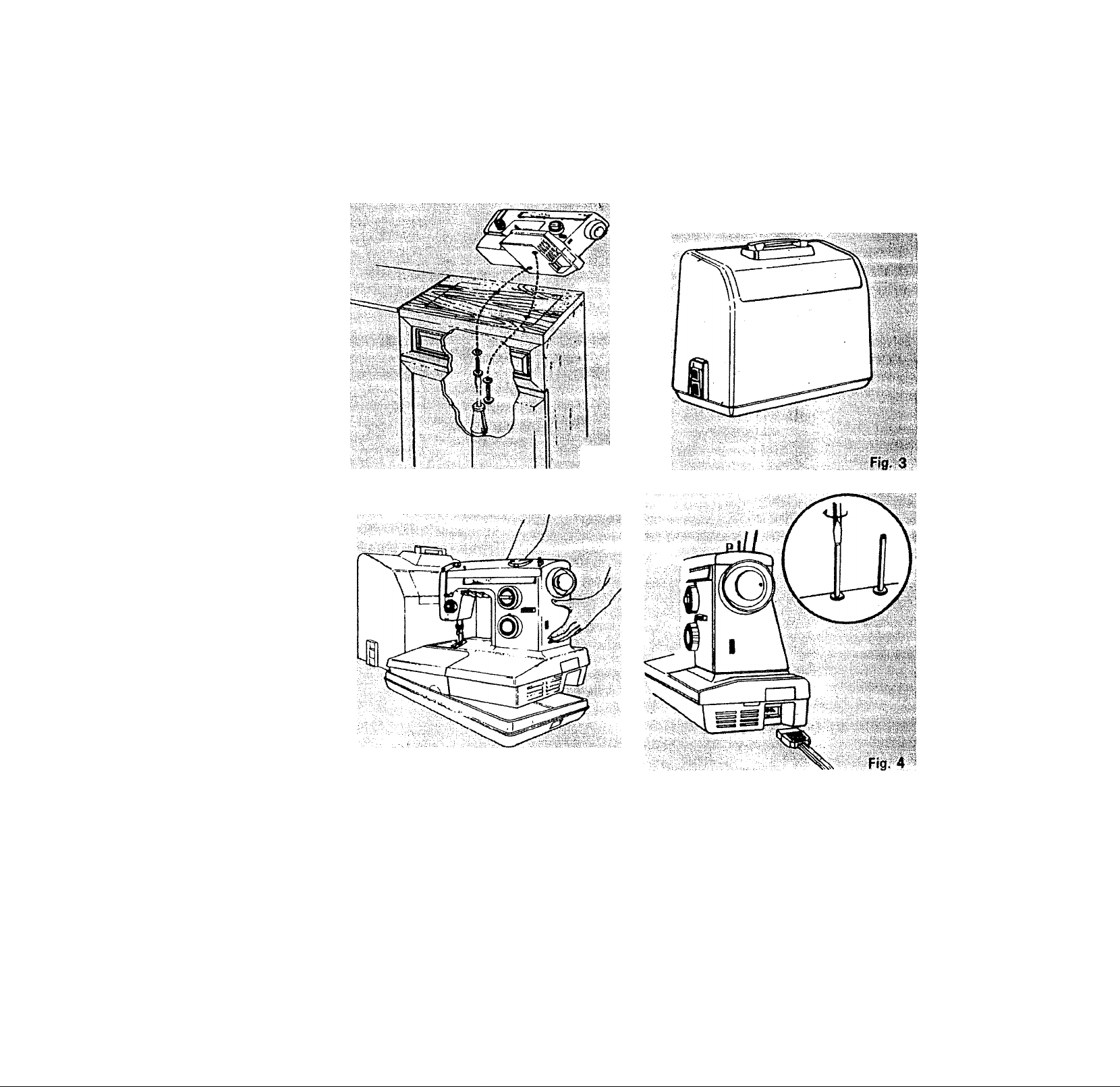
INSTALLING MACHINE (Free-arm type)
fjg-1
Fig. 2
1. To install the machine in cabinet, position
machine head on cabinet platform so that
holes on bottom of machine match those
on board. Insert washers and screws and
tighten into place. (Fig. 1)
2. A separate base and cover is available to
carry the machine when needed. The
base must be removed when machine is
used.
To install machine in carrying case, set
machine into base, with word FRONT in
base facing you. (Fig. 2)
Place cover on machine with word
"SEARS" on handle facing you. The case
slopes in the same direction of the ma
chine. (Fig. 3)
3. Push the speed control plug onto threeprong connector. Plug machine cord into
any 110-120 volt wall outlet. Turn on
power by pushing light and power switch.
(Fig. 4)
4. Spool pins are packed in accessory box.
Screw thread spool pins in place securely
with a screw driver. Position nylon discs
as shown in illustration.

INSTALLING MACHINE (Flat bed type)
0
mm
(D
0
I#*
(D
0
1.
Loosen the two hinge screws under
holes in the rear edge of the machine
bed.
2.
Raise hinge pins in the cabinet or
case. Slip machine head onto pins.
3, Tighten hinge screws securely.
4. Push the speed control plug onto
three-prong connector under the
bed plate. Lower machine head to
front cabinet flap.
5. Plug machine cord into any 110-120
volt wall outlet. Turn on power by
pushing light and power switch.
6. Spool pins are packed in accessory
box. Screw thread spool pins in
place securely with a screw driver.
Position nylon discs as shown in
illustration.
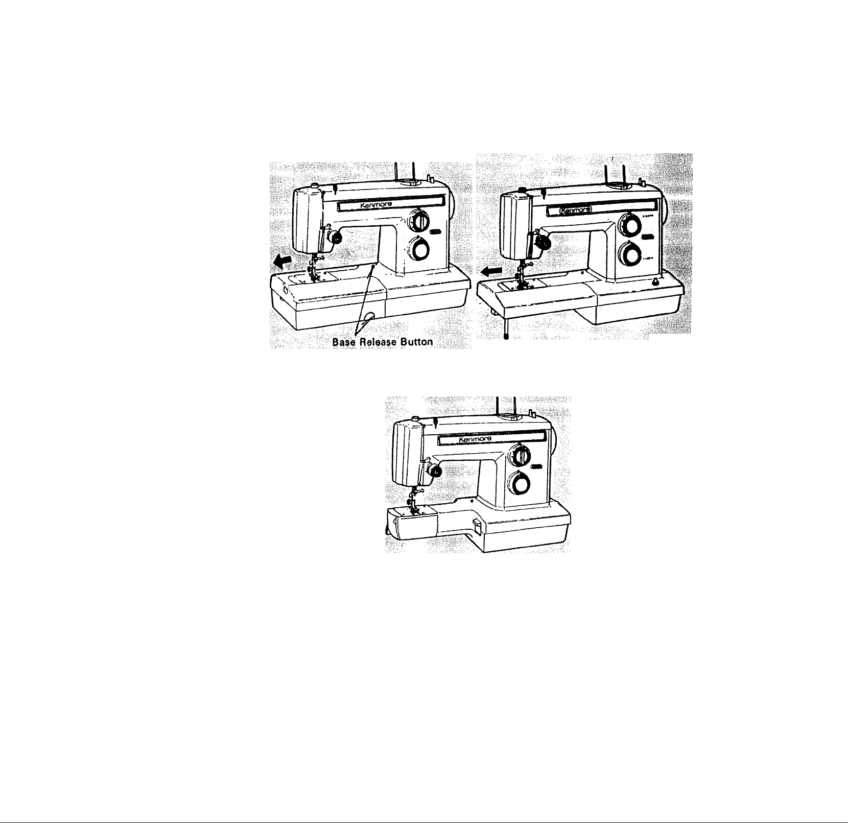
CONVERTING TO FREE-ARM SEWING
Fig. 1
Remove the base from the machine
by pushing the release button (if
applicable) and pulling the base to
the left, (Fig. 1, 2)
Fig. 2
2, To replace the base, simply slide it
along the free arm to its original
position. (Fig. 1)
Note: Base cannot be removed or
replaced unless shuttle cover is
closed.
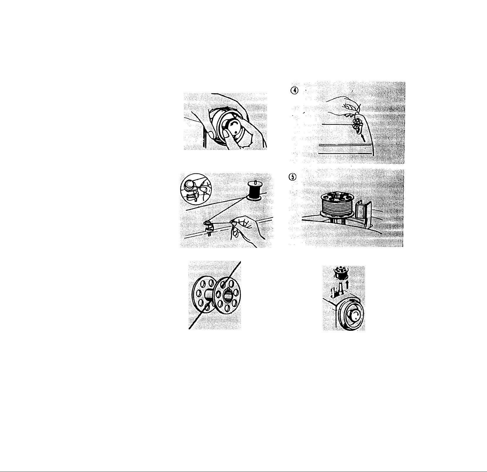
WINDING THE BOBBIN
0
0
0
1. Release clutch by turning clutch
knob toward you.
2. Draw thread from spool through
bobbin winder tension disc as
shown.
3. Pull end of thread through hole in
bobbin as shown.
4. Place bobbin onto bobbin winder
shaft with end of thread coming
from the top of the bobbin. Push
'i,
' '''' y*-a
•f'tt
iii!
bobbin winder latch against bobbin
until it clicks. Holding onto end of
thread, start nhachine. When bobbin
is slightly filled, snip off end of
thread.
5. Start machine. Wind thread until
bobbin winder latch releases.
6. Tighten clutch knob and remove
bobbin.
V "-r i
I
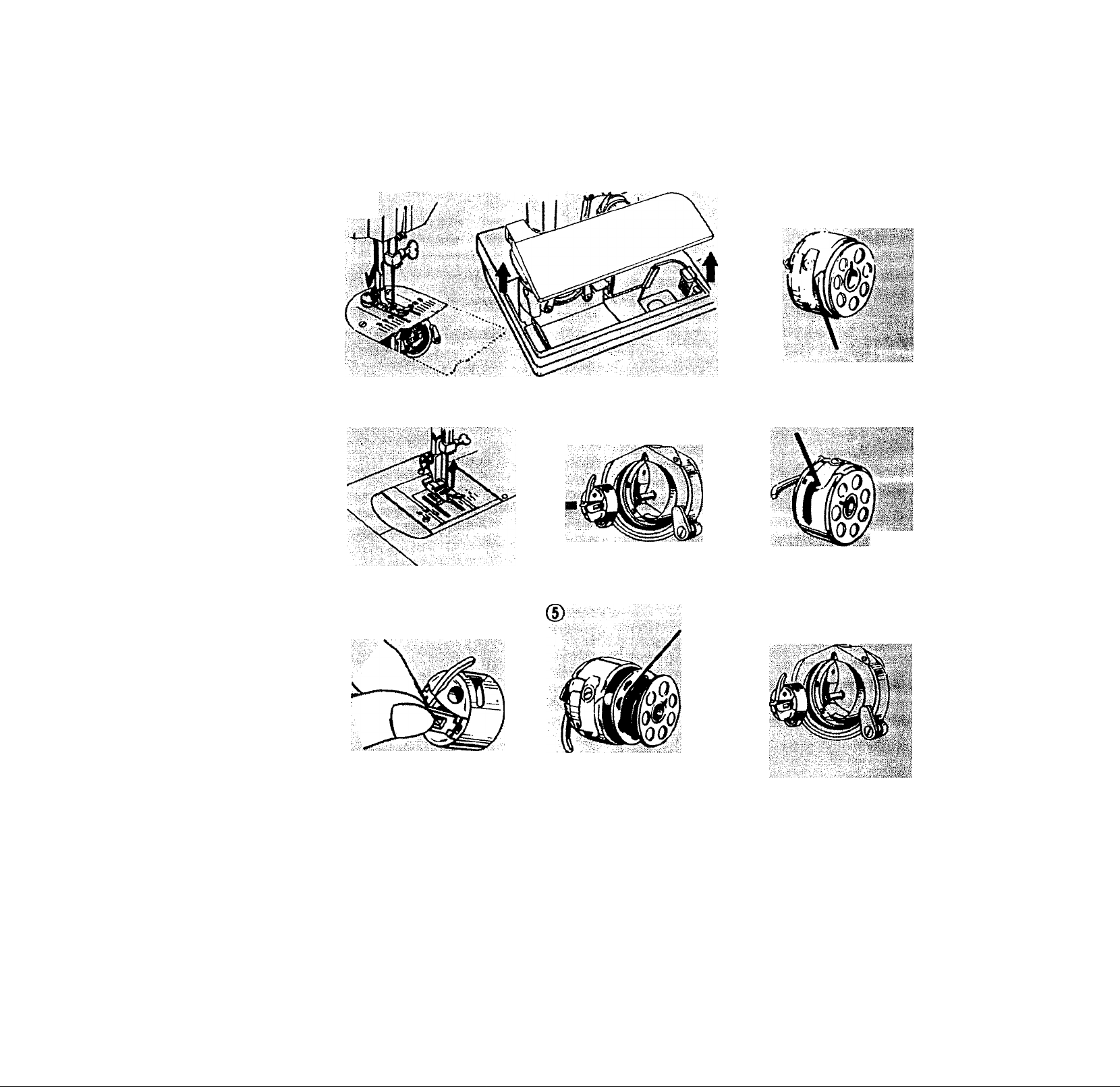
THREADING THE BOBBIN CASE
■ - ■ ..........
0
(D
d)
l|s®l
I*
1. Remove base front cover by push
ing the release button on the left
side. Open the shuttle cover.
2. Raise needle to its highest position
by rotating hand wheel toward
you.
3. To remove bobbin case from shut
tle, pull open latch of bobbin case.
4. Pull bobbin case straight out of
shuttle,
*
5. Insert bobbin into bobbin case mak
ing sure thread is coming from
bobbin as shown.
6. Pull thread through slot of case as
shown.
7. Pull thread under tension spring.
8. Holding latch open, position case
into shuttle, and release latch. Case
should lock into place when latch
is released.
8
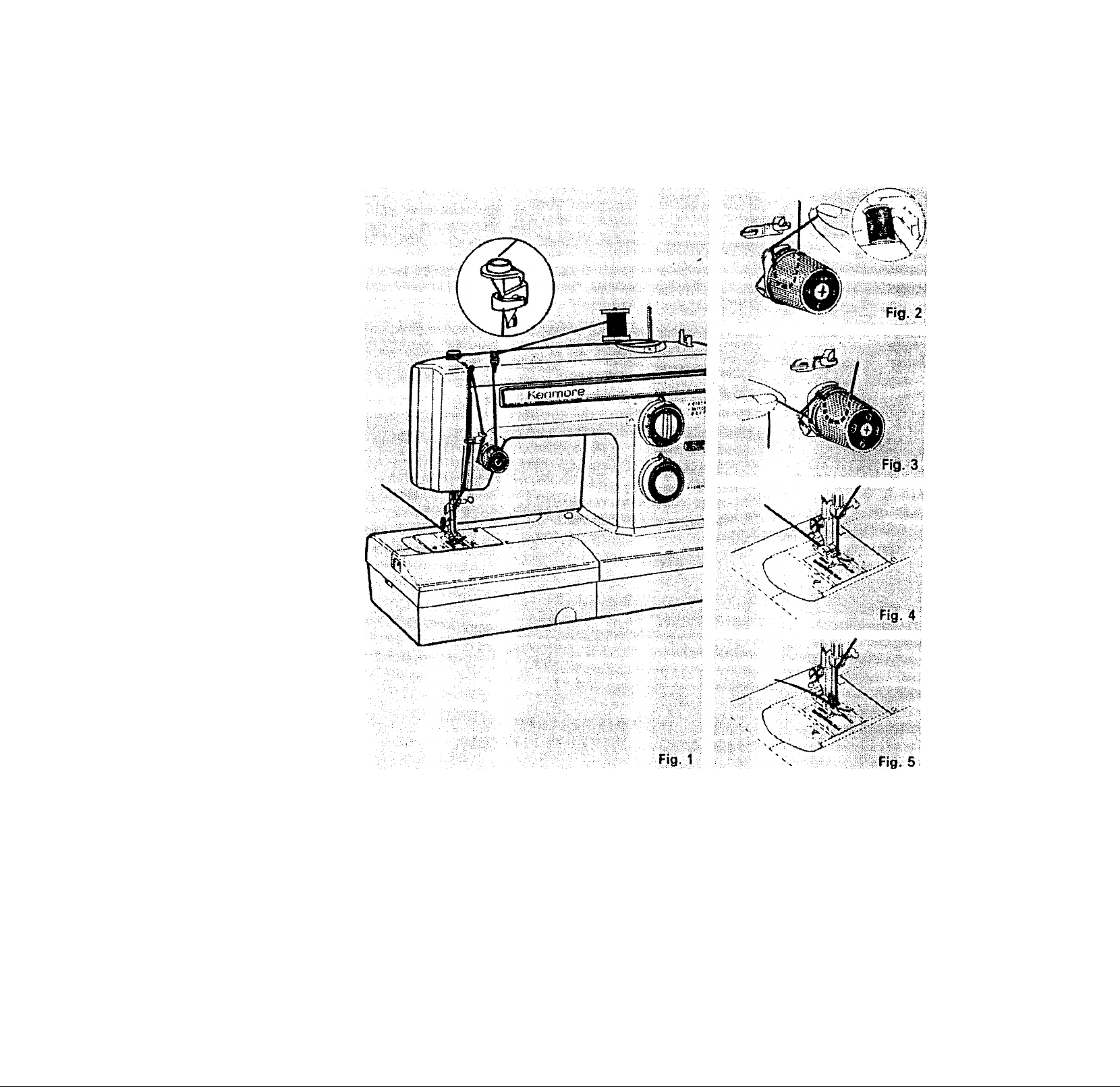
THREADING OF TOP THREAD
Place thread on spool pin as shown
with thread coming from the back of
the spool. Draw thread through the
top thread guide. Holding the spool
stationary with right hand, pull the end
of the thread between the tension discs
as shown. Pull the spring wire loop up
and past the top hook until the thread
can be slipped into the hook (See Fig.
2). When the thread is released, the
spring wire loop will return to position
(See Fig. 3) with thread in proper place.
Release spool of thread and continue to
thread machine exactly as shown.
Needle must always be threaded in
direction as shown in Fig. 4.
Hold needle thread loosely in left hand
and rotate hand wheel toward you one
complete turn. Bring bobbin thread up
by pulling upper thread. (Fig, 5),
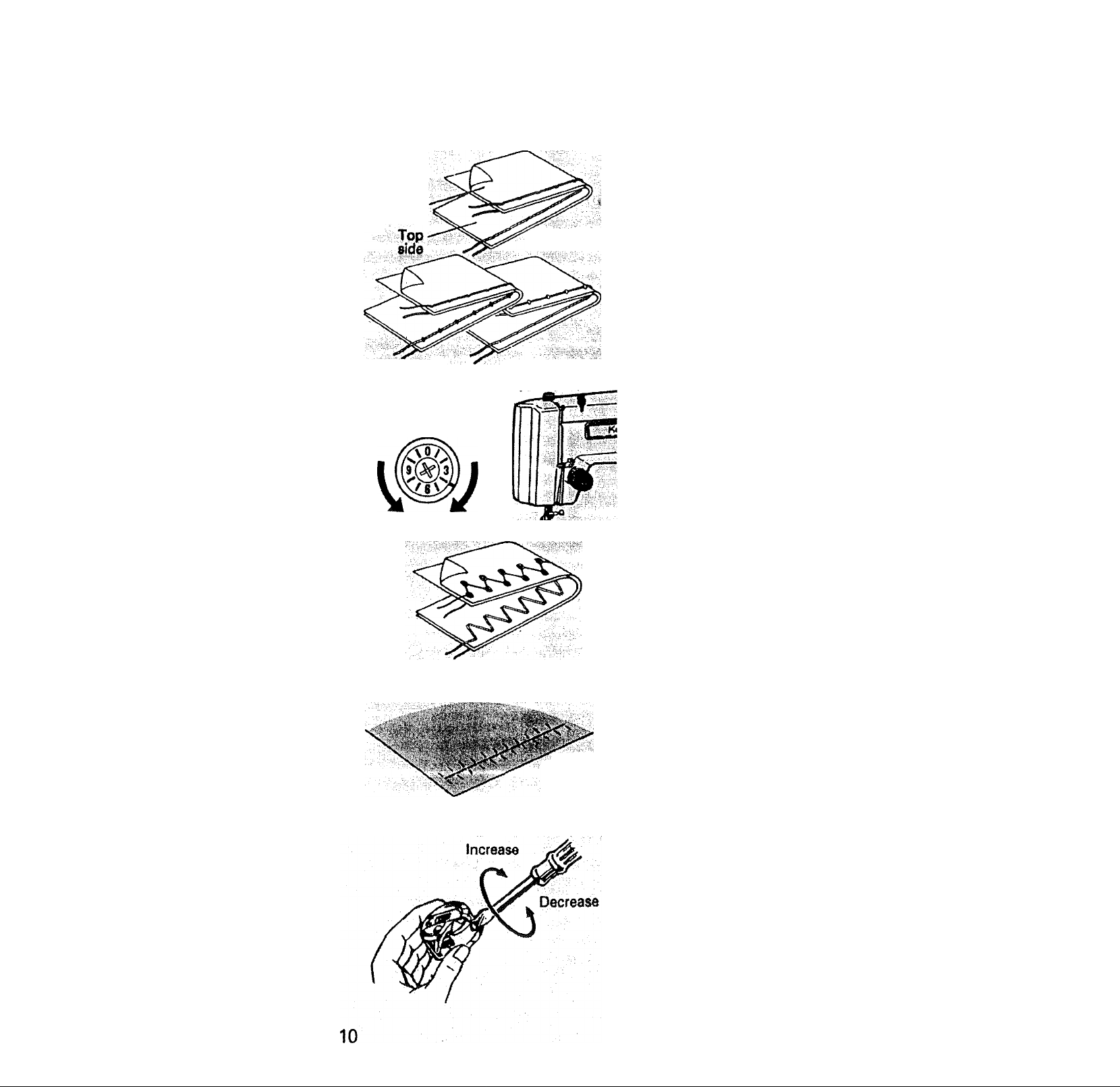
STRAIGHT STITCHING
ADJUSTING TOP THREAD TENSION
Under
side
Top stitch
too tight
X .
D«cr«s«« IncrMM
tension tension
ZIGZAG STITCHING
Well balanced
Top Stitch
too loose
STRAIGHT STITCHING
The good looking appearance of your
stitching Is largely determined by the
balanced tension of both top and bobbin
threads. The tension is well balanced
when these two threads 'lock' In the
middle of layers of fabric you are
sewing.
If, when you start to sew, you find that
the stitching is Irregular, you will need to
adjust the tensron control.
Make any adjustments vyith presser foot
'down'.
1. If the threads are locking on the top
surface with the top thread lying flat,
the top stitch is too tight. Tension
can oe decreased by turning the
tension control to lower numbers.
2. If the reverse is happening with the
threads on the underside of the
fabric, (fie tension is too loose. This
can be corrected by turning the
tension control to higher numbers.
Fabric
puckers
ZIGZAG STITCHING
The top thread may appear on the
bottom depending on the thread, fabric,
type of stitch and sewing speed, but the
bobbin thread must never appear on the
top of the fabric.
ADJUSTING BOBBIN
THREAD TENSION
BOBBIN THREAD TENSION REQUIRES
ADJUSTMENT LESS FREQUENTLY
THAN THE TOP THREAD TENSION.
If the tension is well balanced, but the
fabric puckers badly, both top and
bobbin thread tensions may be too tight
and have to be adjusted.
When adjusting the tension on the
bobbin case, make only slight adjust
ments with a srewdriver.
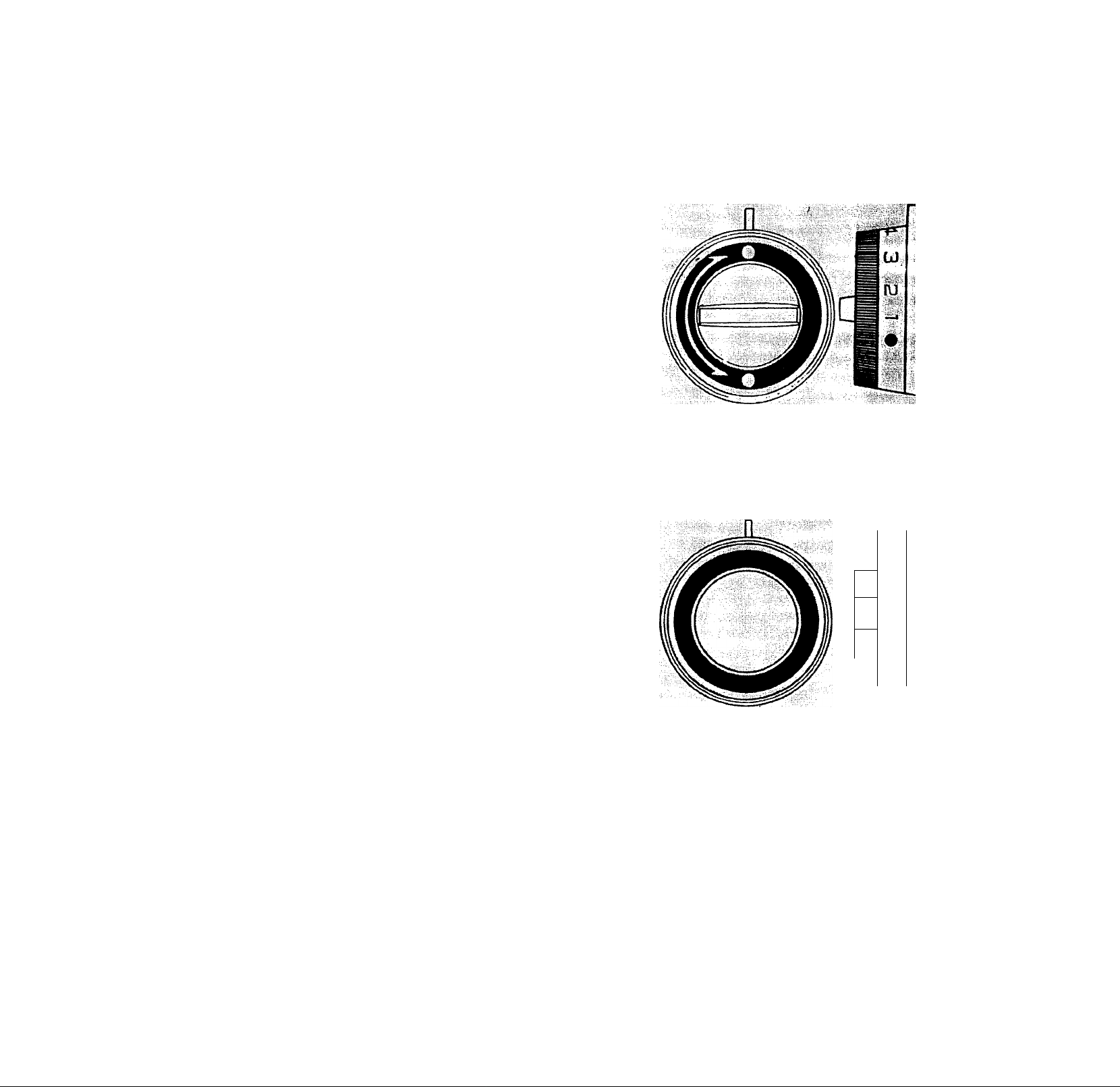
STITCH WIDTH CONTROL
This control regulates the width of the
stitch you select. THE HIGHER THE
NUMBER-THE WIDER THE STITCH.
You may vary your zigzag stitch width
by adjusting this control to the setting
you desire.
This control must be on Red Dot in
order to do straight stitching. Turn only
the outer rim of this control to set the
stitch width. The center of the control
dials the special stitches the machine is
capable of sewing.
STITCH LENGTH CONTROL
The stitch length control regulates the
length of the stitch you select. THE
HIGHER THE NUMBER-THESHORTER
THE STITCH.
The number on stitch length control
indicates the approximate number of
stitches per inch. The stitch setting you
use will be determined by the thickness
of the fabric you are sewing.
ff
p
fU
0
00
A longer stitch setting should be used
for thicker fabric or more layers of fabric.
The middle range of the control is the
10-12 stitch per inch range which is the
most commonly used.
A basting stitch is made by using the
longest possible stitch setting-6 stitches
per inch. The red marking on the
control is the setting used for the
shortest stitches such as in Satin
Stitching.
d)
11
y ■•'#
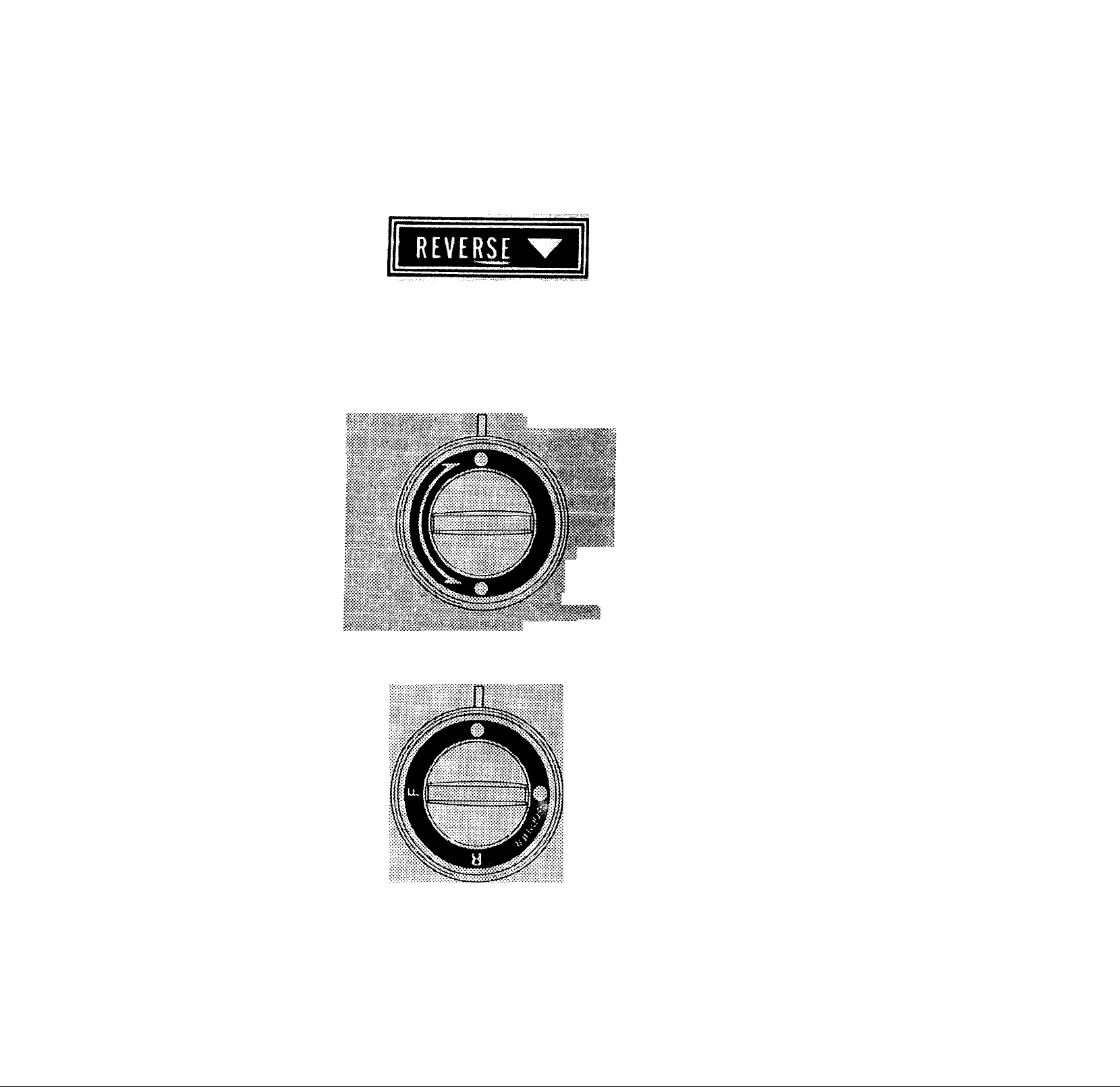
REVERSE STITCH CONTROL
It Is best to begin and end seams with a
few stitches taken In reverse. This is
called back tacking. Back tacking
fastens the ends of the seams firmly and
prevents raveling.
When reverse stitching is needed, turn
the control clockwise and hold there
during sewing. The fabric will imme
diately start feeding backwards and
seam will be fastened.
SPECIAL STITCH MODIFI
ER AND BUTTONHOLE
CONTROL
This control gives you the means of
varying the stitches on the Special
Stitch Dial. When the pointer is turned
to the Red Dot, the machine sews
forward only. When the pointer is
turned to the White Dot, the forward
designs are varied by the machine
sewing in a forward and reverse manner.
Carefully read directions given in the
next section of the book in order to
accomplish the various stitches
correctly.
12
This control is also used in making
buttonholes (Model 1525 only). Detailed
instructions are given in the next section
s
f
of the book.
SPECIAL STITCH DIAL
There are certain types of utility stitches you will use often in your honrte
sewing. This control enables you to just dial the stitch you need for the
task at hand. '
All stitches printed in red on the dial must be sewn with the Special Stitch
Modifier set at the Red Dot. -
To make the stitches printed in black on this dial, the Special Stitch Modifier
must be set at the White Dot.
THE RED DOT SETTING
The setting illustrated above is the one used for most of your stitching. At this
setting you may straight stitch, stretch stitch and make a simple zig zag stitch.
As each stitch is dependent upon the settings of your other controls, carefully
read the directions in the next section of the book for the various stitches.
BLIND STITCH AND OVERLOOK STRETCH STITCH <|S
Blind hems are made by using the setting illustratedc with the Stitch Modifier set
on the Red Dot. When the Modifier is set on the White Dot, overcast stretch
stitching is made.
SPECIAL BOX STITCH AND ELASTIC STRETCH
The setting illustrated is used for special edge finishing and special stretch stitch
for sewing elastic such as sportswear, girdles and other garments that require
stretch. See next section of this book for detailed use of the stitches.
13
SPECIAL MENDING STITCH AND SMOCKING STRETCH :i:8i
You will iind that much of your sewing is in the mending category. For this
reason you have been provided with a stitch for the repair of tears. It is
accomplished with the illustrated setting and the Modifier set at the Red Dot
When the Modifier is turned to the White Dot a Smocking Stitch results. For
directions see the next section of this book.
SERGING OR PINE LEAF STRETCH
Serging or pine leaf stretch is used for seam finishing on all types of fabrics. It is
a stitch used in the garment industry. It forms a good looking seam, stitching
and overcasting the edges. This stitch is useful for seaming of swimwear, stretch
ski pants and other types of knit sportswear. Modifier must be set on the White
Dot. ■
If Modifier is set on the red dot, a Shell Stitch can be made on nylon tricot.
BUTTONHOLE SETTING
The three settings illustrated are used in making a bar tacked buttonhole.
Detailed instructions are given in the next section of the book.
14
t -«I ^ ^ ^ «sysi^x-
OTHER ADJUSTMENTS OF MACHINE IN SEWING
In addition to the obvious controls of your machine, there are other small
regulators and controls to aid you in using your sewing machine.
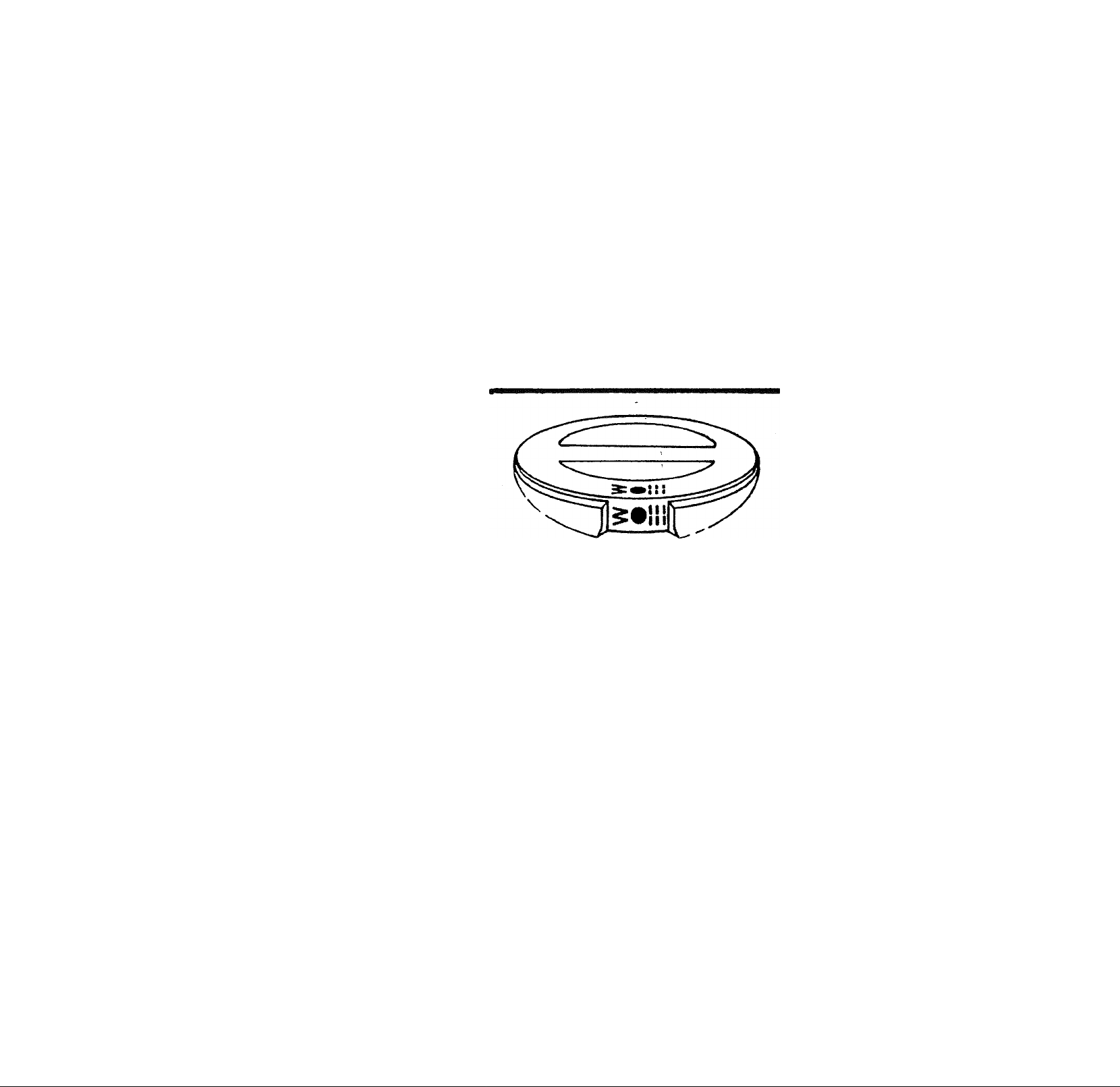
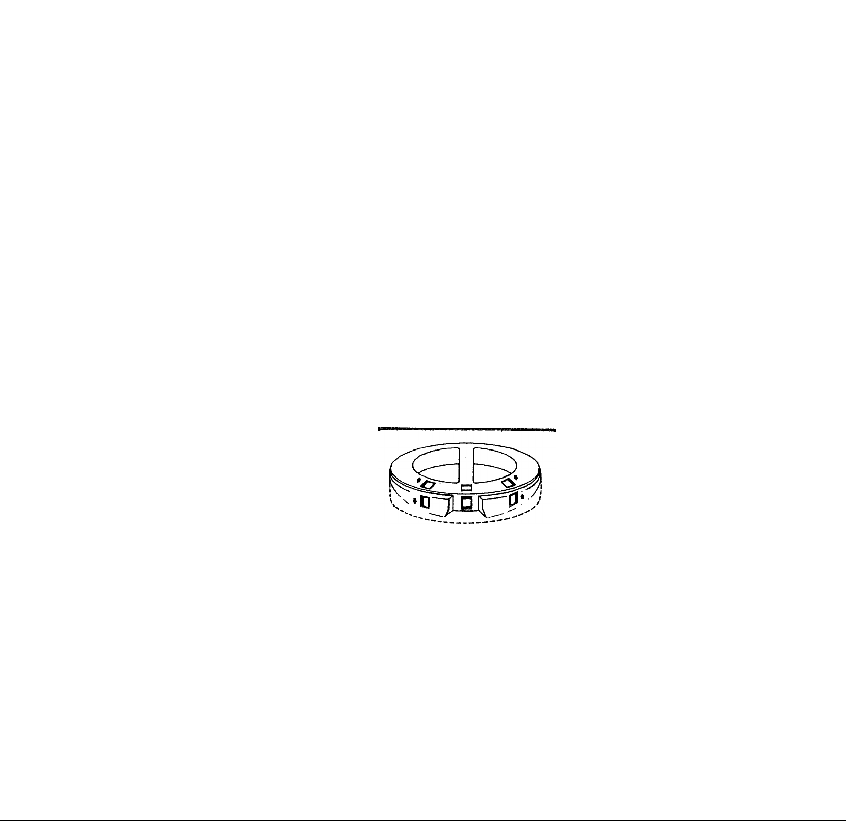
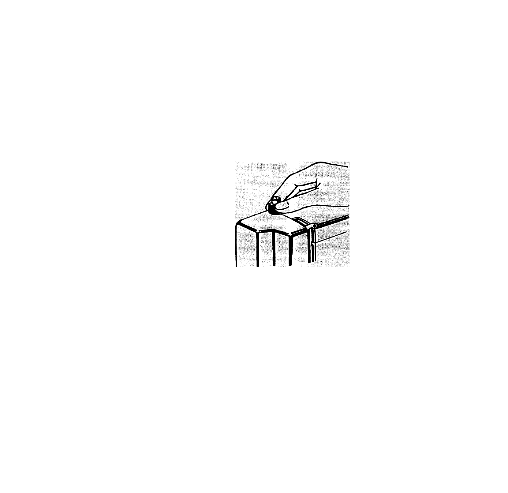
PRESSURE REGULATOR
" 'Is i
Push down the outer ring of the pressure regulator. This will release the
pressure on the presser foot. (See above).
To increase the pressure, push down inner pin until a suitable pressure is
obtained.
Insufficient pressure may cause poor feeding of the fabric, skipped stitches,
or difficulty In guiding the fabric. If feed dogs or presser foot marks appear
on the fabric, reduce the pressure.
When sewing multiple thickness or heavy fabric, reduce the pressure. Increase
pressure when sewing lighter weight fabrics.
15
 Loading...