

Page 1

ProTig
410 Hyundai
Operating manual • English
EN
Page 2

Page 3

OPERATING MANUAL
English
ProTig 410 Hyundai / © Kemppi Oy / 1135
Page 4

ProTig 410 Hyundai / © Kemppi Oy / 1135
EN
CONTENTS
1. PREFACE ................................................................................................................................ 3
1.1 General ....................................................................................................................................... 3
1.2 Product introduction ............................................................................................................ 3
1.2.1 Operation control and connectors ................................................................................. 4
1.2.2 Accessories and cables .................................................................................................... 6
2. INSTALLATION ................................................................................................................. 8
2.1 Assembly of TIG/MMA equipment ................................................................................... 8
2.1.1 Installation of power source ........................................................................................... 8
2.1.2 Assembly of transport wagon and mounting of Pro power source to wagon ............ 8
2.1.3 Mounting of Protig 410 unit onto the power source (gure page 5) ........................... 8
2.1.4 Mounting of Protig 410 control panel ............................................................................ 8
2.1.5 Connecting cables ........................................................................................................... 8
2.1.6 Connecting torch and extension cable ......................................................................... 8
2.1.7 Use as terminal unit ......................................................................................................... 9
2.1.8 Assembly and controls of MIG / TIG / MMA equipment ................................................ 9
2.1.9 Remote control units ....................................................................................................... 9
2.2 Installation of TIG/MMA equipment ................................................................................ 9
2.2.1 Choice of electrode and ow amount of shielding gas ................................................ 9
2.3 Shield gas ................................................................................................................................10
2.3.1 Installing gas bottle .......................................................................................................10
2.4 Main switch I/O .....................................................................................................................11
2.5 Operation of cooling unit (Procool 10, 30) .................................................................11
3. OPERATIONS OF PANELS .....................................................................................11
3.1 Control panel TL 6271265 .................................................................................................11
3.2 Control panel TX 6271266 .................................................................................................16
4. ACCURACY OF PANEL DISPLAY ......................................................................21
5. REMOTE CONTROL UNIT ......................................................................................21
6. MAINTENANCE ..............................................................................................................22
6.1 Welding torch ........................................................................................................................22
6.2 Cables ........................................................................................................................................22
7. OPERATION DISTURBANCES ............................................................................23
7.2.1 Disposal of the machine ................................................................................................24
8. ORDERING NUMBERS .............................................................................................24
9. TECHNICAL DATA ........................................................................................................25
2
Page 5

1. PREFACE
1.1 GENERAL
Congratulations on choosing the ProTig equipment. Used correctly, Kemppi products can
signicantly increase the productivity of your welding, and provide years of economical
service.
This operating manual contains important information on the use, maintenance and safety of
your Kemppi product. The technical specications of the equipment can be found at the end
of the manual.
Please read the manual carefully before using the equipment for the rst time. For your
own safety and that of your working environment, pay particular attention to the safety
instructions in the manual.
For more information on Kemppi products, contact Kemppi Oy, consult an authorised Kemppi
dealer, or visit the Kemppi web site at www.kemppi.com.
The specications presented in this manual are subject to change without prior notice.
Important notes
Items in the manual that require particular attention in order to minimise damage and
personal harm are indicated with the ’NOTE!’ notation. Read these sections carefully and follow
their instructions.
Disclaimer
While every eort has been made to ensure that the information contained in this guide
is accurate and complete, no liability can be accepted for any errors or omissions. Kemppi
reserves the right to change the specication of the product described at any time without
prior notice. Do not copy, record, reproduce or transmit the contents of this guide without
prior permission from Kemppi.
ProTig 410 Hyundai / © Kemppi Oy / 1135
EN
1.2 PRODUCT INTRODUCTION
Protig 410 is a TIG ignition unit for demanding professional use. The unit is controlled by
means of a microprocessor and ignition spark is generated by means of thyristors.
These operation instructions are for Protig 410 ignition unit, assembly and installation of TIG
equipment as well as panel functions. In addition instructions describe assembly of Mig/TIG/
MMA equipment, cables and main operations of installation.
3
Page 6
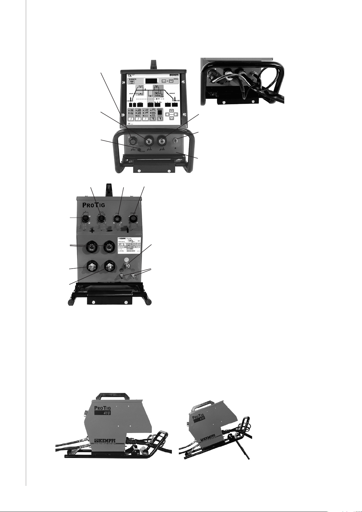
1.2.1 Operation control and connectors
Start connection
of torch
Air-cooled torch
Switch for air-/
liquid-cooled torch
Liquid-cooled torch
Cooling liquid connection,
welding torch
ProTig 410 Hyundai / © Kemppi Oy / 1135
EN
X16
X17
X13
X12
X11
X11 Welding current connections: Supply X12 Welding current connections: Supply +
X13 Earth connection
X14 Connection of welding torch
X15 Connection for control cable: Pro power source
X16 Connection for control cable: Procool
X17 Connection for control cable: Remote control unit
X18 Start connection: Remote control unit
X15
X18
Shield gas
Cooling liquid
X14
4
Page 7
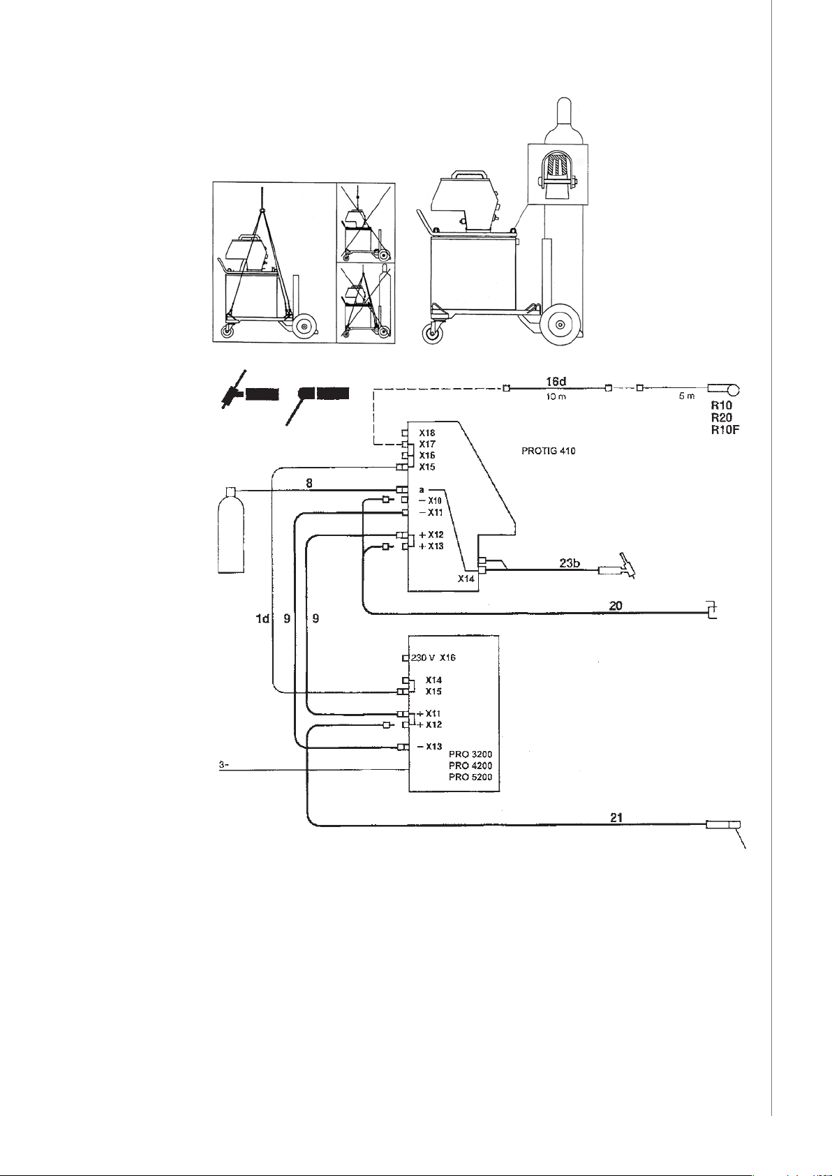
Remote control unit
ProTig 410 Hyundai / © Kemppi Oy / 1135
EN
Pro Power source
1d Control cable
8 Shielding gas hose Snap connector - 0
9 Welding current cable
16d Extension cable for remote control
20 Earth cable
21 MMA welding cable
23b TIG torch, air-cooled
5
Page 8
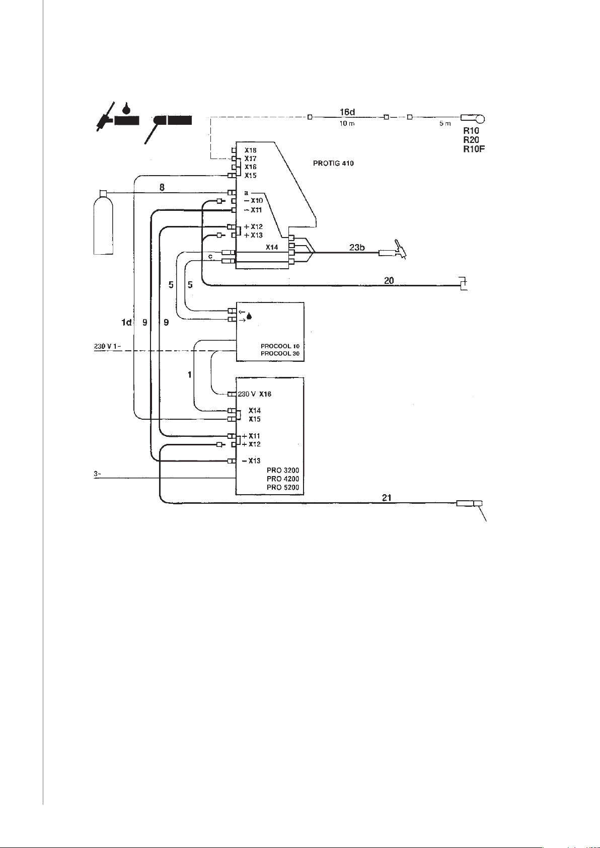
1.2.2 Accessories and cables
ProTig 410 Hyundai / © Kemppi Oy / 1135
Remote control unit
EN
Pro: Power source
Procool 10, Procool 30: Cooling liquid circulation unit
1d Control cable
5 Cooling liquid hose, R3/8 - Snap connector
8 Shielding gas hose, Snap connector - 0
9 Welding current cable
16d Extension cable for remote control
20 Earth cable
21 MMA welding cable
23b TIG torch, liquid-cooled
23c TIG extension cable, air-cooled
23d TIG extension cable, liquid-cooled
6
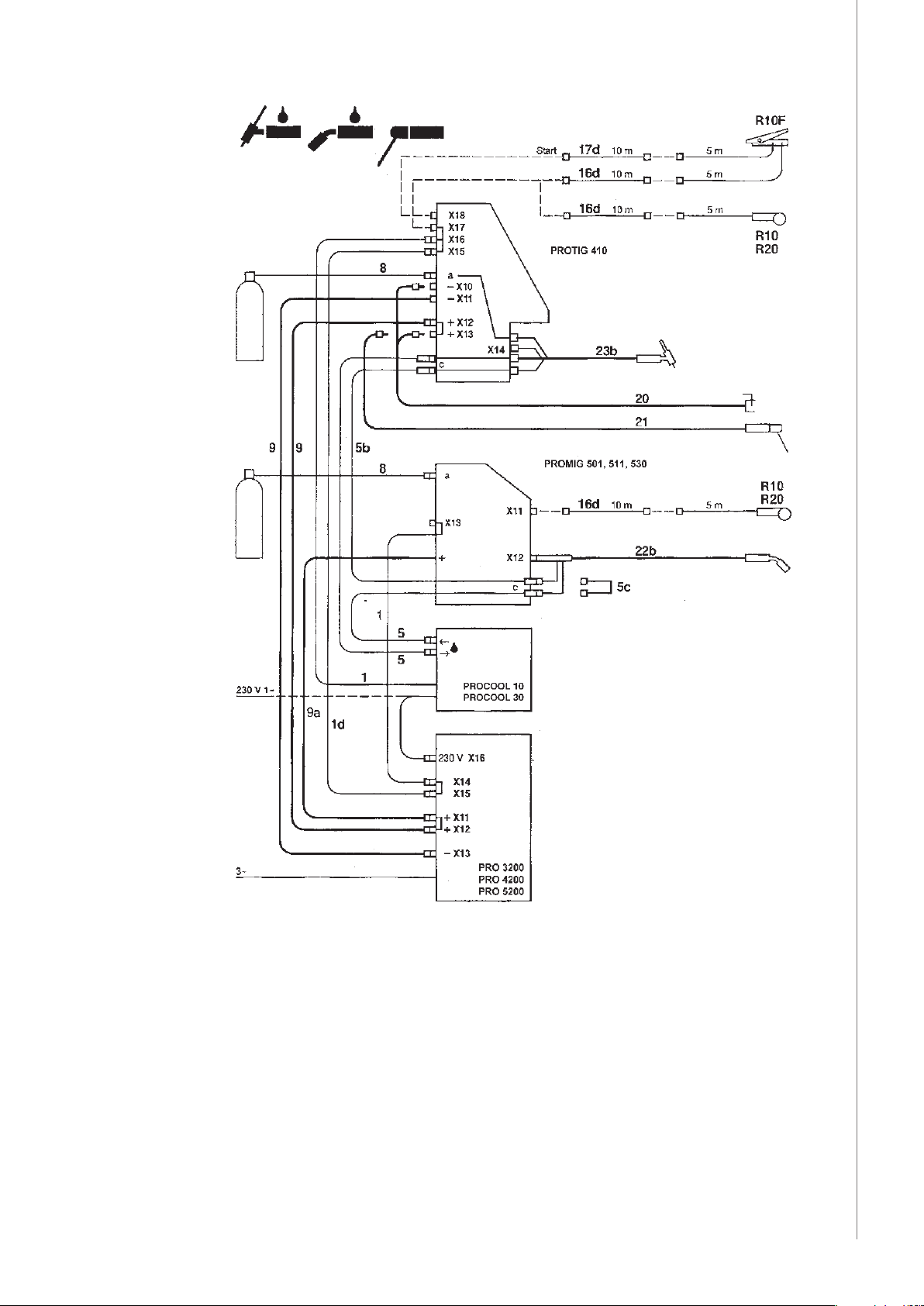
Page 9
Remote control unit
ProTig 410 Hyundai / © Kemppi Oy / 1135
EN
Pro 3200, 4200, 5200: Power source
Procool 10, 30: Cooling liquid circulation unit
Promig 501, 511, 530: MIG-MAG wire feeder
1d Control cable
5 Cooling liquid hose, R3/8-Snap connector
5b Cooling liquid hose, Snap conn. - Snap conn.
5c Cooling liquid hose, Bridge element
8 Shielding gas hose, Snap connector - 0
9a Welding current cable
16d Extension cable for remote control
17d Start extension cable
7
Page 10

20 Earth cable
21 MMA welding cable
22b Mig gun liquid-cooled
23b TIG torch, liquid-cooled
23d TIG extension cable, liquid-cooled
2. INSTALLATION
2.1 ASSEMBLY OF TIG/MMA EQUIPMENT
Assemble the equipment in below-mentioned order and follow mounting and operation
instructions which are delivered with packages.
2.1.1 Installation of power source
NOTE! Connection of mains cable and mounting operations as well as change of plug should only
ProTig 410 Hyundai / © Kemppi Oy / 1135
2.1.2 Assembly of transport wagon and mounting of Pro power source to wagon
be carried out by a competent electrician.
Read paragraph: ”Installation” in operation instructions (1913130) for Pro power sources and
carry out the installation according to that.
P20 6185261 air-cooled TIG equipment
P30W 6185262 liquid-cooled TIG equipment
P40, P40L 6185264, 6185264L air-cooled TIG equipment
Lifting of wagon together with bottle is forbidden due to safety reasons!
EN
2.1.3 Mounting of Protig 410 unit onto the power source (gure page 5)
NOTE! Lock the Protig unit carefully as shown in g. onto pro power source. Loose unit might cause
a danger situation.
2.1.4 Mounting of Protig 410 control panel
TL 6271265
TX 6271266
2.1.5 Connecting cables
Follow enclosed gures:
Air-cooled equipment on page 5
Liquid-cooled equipment on page 6
When connecting cables take into consideration the fact that the most generally used polarity
in TIG welding is the torch - and ground cable +. In MMA welding the polarity is generally
on the contrary (Electrode holder+). Follow instructions as shown on page 5 and 6 when
changing welding method.
2.1.6 Connecting torch and extension cable
Connection to the Protig 410 unit is shown on page 5 (air-cooled torch) and on page 6 (liquidcooled torch).
Tighten connector of torch carefully in order to avoid heating, contact disturbances and
mechanical damage of connector as well as gas leakage to inside of connector.
NOTE! Check by connection of water and gas hoses that there is no dirt, metal powder or other
waste. Waste might cause blockage of water circulation, throughburning of torch, or stopping or
breaking of pump (Procool 10, Procool 30).
Connect water hoses of torch and interconnecting cable as shown in gure on page 6. (These
are xed to tube frame). Fix water hoses (torch - interconnecting cable - Procool) in such a way
that those having red code always are connected to corresponding red counter connectors
and the blue ones respectively to blue counter connectors.
8
Page 11

NOTE! If connections cross, cooling liquid is circulating to wrong direction in torch and torch
handle and neck body might be considerably heatened.
2.1.7 Use as terminal unit
Between power source and the Protig 410 unit are available 10 m interconnecting cables
which are inside of mutual power.
On page 5 are shown following mecanical operations which are involvel in use of unit.
2.1.8 Assembly and controls of MIG / TIG / MMA equipment
Connecting cables are shown on page 7 (liquid-cooled).
Circulation systems of liquid-cooled torches are series connected. Read carefully warnings in
paragraph 6.
Do not forget to change polarity according to paragraph 5 when you go over from MMA
welding to TIG welding.
Equipment will automatically select Mig welding method and controls when you press
operation switch of Mig gun and respectively TIG welding method when you press switch of
TIG torch.
Remote controls for Mig or TIG welding operate from remote control units which are
connected to respective Promig 501/511/530 and Protig 410 units.
You can select MMA welding from panel of one or the other unit, when remote control for
MMA welding is operating from remote control unit which is connected to device in question.
NOTE! At welding and at no-load of MMA welding also other welding tools are exposed to voltage
depending on polarity. Be careful that welding tools won`t produse any short-circuits.
ProTig 410 Hyundai / © Kemppi Oy / 1135
2.1.9 Remote control units
Connect remote control unit as shown in gures on page 5 or 6. Operation of remote control
unit is explained on page 21.
2.2 INSTALLATION OF TIG/MMA EQUIPMENT
Fasten earthing press of ground cable carefully, preferably direct to welding piece. Contact
surface of press always should be as large as possible.
Clean the fastening surface from paint and rust!
Use in your TIG/MMA equipment 50 mm2 cables. Thinner cross-sectional areas might cause
overheating of connectors and insulations.
Make sure that the torch being in your use is designed for max. welding current needed by
you! Never use a damaged torch!
2.2.1 Choice of electrode and ow amount of shielding gas
Use argon as TIG shielding gas. Electrode size and shielding gas ow rate are dened by
welding current size. The table below is given only as a guide.
Welding
current
A ø mm number ø mm l/min
5 – 80 1,0 4 / 5 6,5 / 8,0 5 – 6
70 – 150 1,6 4 / 5 / 6 6,5 / 8,0 /9,5 6 – 7
140 – 250 2,4 6 / 7 9,5 / 11,0 7 – 8
225 – 330 3,2 7 / 8 11,0 / 12,5 8 – 10
330 – 4,0 10 16,0 10 – 12
Electrode Gas nozzle
EN
Gas flow rate
9
Page 12
2.3 SHIELD GAS
NOTE! Handle gas bottle with care. There is a risk for injury if gas bottle or bottle valve is damaged!
For welding stainless steels, mixed gases are normally used. Check that the gas bottle valve
is suitable for the gas. The ow rate is set according to the welding power used in the job. A
suitable ow rate is normally 8 - 10 l/min. If the gas ow is not suitable, the welded joint will
be sporous. Contact your local Kemppi-dealer for choosing gas and equipment.
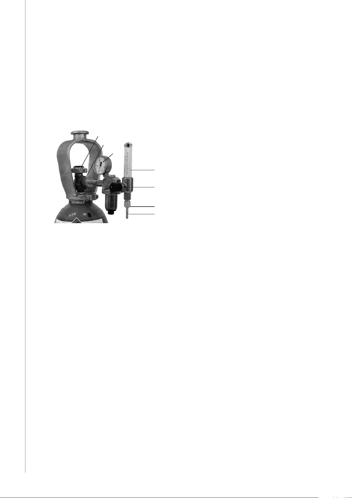
2.3.1 Installing gas bottle
NOTE! Always fasten gas bottle properly in vertical position in a special holder on the wall or on a
carriage. Remember to close gas bottle valve after having nished welding.
ProTig 410 Hyundai / © Kemppi Oy / 1135
A
C
F
G
B
E
D
EN
Parts of gas ow regulator
A. Gas bottle valve
B. Press regulation screw
C. Connecting nut
D. Hose spindle
E. Jacket nut
F. Gas bottle pressure meter
G. Gas hose pressure meter
The following installing instructions are valid for most of the gas ow regulator types:
1. Step aside and open the bottle valve (A) for a while to blow out possible impurities from
the bottle valve.
2. Turn the press regulation screw (B) of the regulator until no spring pressure can be felt.
3. Close needle valve, if there is one in the regulator.
4. Install the regulator on bottle valve and tighten connecting nut (C) with a wrench.
5. Install hose spindle (D) and jacket nut (E) into gas hose and tighten with hose clamp.
6. Connect the hose with the regulator and the other end with the wire feed unit.Tighten
the jacket nut.
7. Open bottle valve slowly. Gas bottle pressure meter (F) shows the bottle pressure.
NOTE! Do not use the whole contents of the bottle. The bottle should be lled when the bottle
pressure is 2 bar.
8. Open needle valve if there is one in the regulator.
9. Turn regulation screw (B) until hose pressure meter (G) shows the required ow
(or pressure). When regulating ow amount, the power source should be in switched on
and the gun switch pressed simultaniously.
Close bottle valve after having nished welding. If the machine will be out of use for a long
time, unscrew the pressure regulation screw.
10
Page 13

2.4 MAIN SWITCH I/O
When you turn the main switch of the Pro power source into I-position, pilot lamp close to it
is lighted and the equipment is ready for welding. The equipment is returned to that welding
method with which the welding was last carried out before the main switch was turned to
zero position.
NOTE! Always start and switch o the machine with the main switch, never use the mains plug as a
switch.
2.5 OPERATION OF COOLING UNIT PROCOOL 10, 30
Operation of cooling unit is controlled in such a way that pump is started when welding is
started. After welding stop pump is rotating for approx. 5 min cooling the liquid to ambient
temperature. Purpose of this operation is to make maintenance intervals of pump longer.
Read in operation instructions for the Procool 10 / Procool 30 unit the trouble situations of the
liquid circulation system and protection against torch etc. damage.
3. OPERATIONS OF PANELS
3.1 CONTROL PANEL TL 6271265
H26 P23 P24 P25
P21
P22
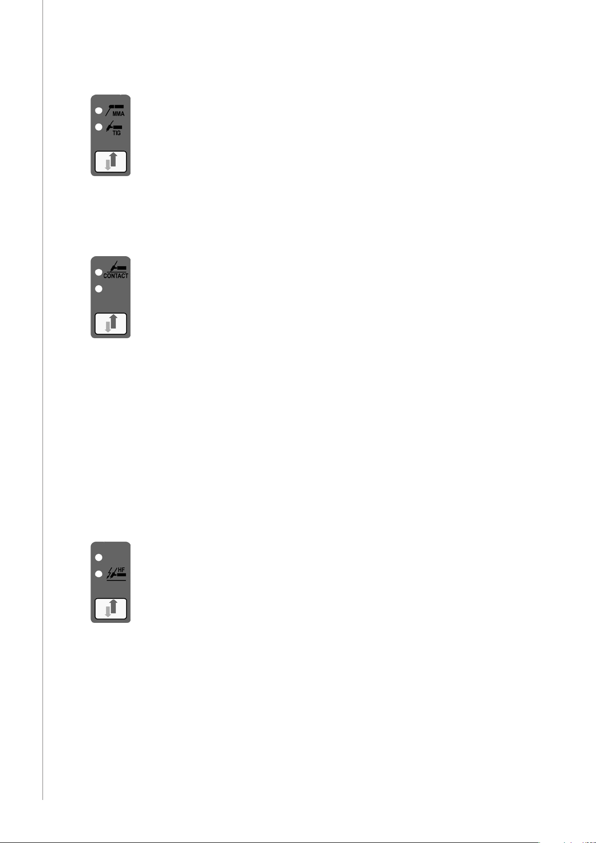
S21 Selection of MMA/TIG welding
S22 Selection of TIG ignition method
S23 Selection of operating mode of torch switch
S27 Selection of adjustable parameter
S28 +/- adjustment of selected parameter
P21 Display for pre-gas time
P22 Display for current up-slope time
P23 Display of welding current
P24 Display of down-slope time of current
P25 Display of post gas time
Led-lamp is illuminated to show those selections and operations which are used.
H21
S21
H22
S23S22 S27
ProTig 410 Hyundai / © Kemppi Oy / 1135
H24
EN
H25
S28
11
Page 14
ProTig 410 Hyundai / © Kemppi Oy / 1135
EN
3.1.1 Selection of MMA/TIG welding
Don`t forget to change polarity of voltage when you go over from one method to another: TIG
welding generally in torch-, MMA welding generally in eletrode holder +, see connection on
page 4 or 5.
3.1.2 Selection of TIG ignition method
Contact ignition:
Spark generation is prevented and arc will be ignited as follows:
1. Touch work piece with an electrode.
2. Start power source with the torch switch.
3. Lift electrode o from work piece in which case arc will be ignited. If arc is not ignited
within 1 s, the ignition must be repeated.
Scratch ignition is not recommended.
Control of ignition spark
Spark power may cause interference with eletronics equipment, which are not properly
protected. If there is interference, use contact ignition.
In order to reduce spark voltage in dicult interference situations, take contact with
authorized Kemppi service work shop.
Spark ignition:
Arc is ignited with high frequency with high voltage spark without touching work piece.
Use of torch switch starts spark generation. Spark strikes from electrode to work piece and arc
is ignited. Welding current is immediately set at set value. Spark distance, shielding gas ow
and current through earthing press have a profound eect on ignition.
If arc is not igniteed within 1s, the ignition must be repeated.
NOTE! Be careful that the torch tip is not touching near skin, clothes or components which are
sensitive for damage, like panels, connectors or switches.
12
Page 15

3.1.3 Selection of torch switch operation
2-function:
1. After having pressed torch switch down, shielding gas starts to ow. Welding starts after
ca. 0,3 s pregas time, welding current goes immediately up to current level according to
settings.
2. When you release torch switch up, welding current begins to go down smoothly, and
current is cut o after time dened by down-slope time. When welding current is zero,
there begins post gas time.
3. Tack weld automatics with 2-function: if welding time was less than 3s, there won`t come
any down-slope time.
Begin trial operation of unit with this mode of switch in order to avoid confusion. Go through
all operations and controls of panel.
ProTig 410 Hyundai / © Kemppi Oy / 1135
4-function:
1. Press torch switch down, shielding gas begins to ow.
2. Release the switch up, welding is started as above. Welding is continued, when the
switch is released.
3. Press the switch again down, welding is continued.
4. Release the switch up, welding is stopped as above.
Stopping unintentional start
With spark ignition:
If arc is not ignited, e.g. torch has not been directed towards work piece, ignition spark will go
out within 1 s from pressing down the torch switch. If eletrode is fastened on the work piece
when the torch is pressed down, welding current will be switched o immediately and there
comes no ignition spark.
With contact ignition:
If electrode is fastened on the work piece, when torch is switched down, and electrode is not
lifted o from the work piece, welding current is switched o within 1 s.
EN
13
Page 16

3.1.4 Adjustment of control unit
With + and - keys, parameters (time or current) are adjusted to higher or lower values.
Adjustable operation is selected with arrow keys: welding current, current down-slope time or
post gas time.
Adjustment speed is growing during adjustment.
ProTig 410 Hyundai / © Kemppi Oy / 1135
3.1.5 Parallel control unit for welding current
Controlling is directed only on welding current, in which case changing current is rapid in
operation mode. Control unit is operating in parallel with key S39 on right lower corner
of panel if welding current is adjusted from them. Parallel control unit cannot be used for
adjusting times or per cents.
EN
3.1.6 Pre-gas time display and current up-slope time display
Control ranges are 0 – 9 s.
3.1.7 Display of current down-slope time
Control range is 0 – 30 s.
3.1.8 Display of post gas time
Control range is 0 – 99 s.
3.1.9 Display of welding current
On no-load the meter shows set value of welding current and at welding true value.
14
Page 17

3.1.10 Local and remote control of welding current
Local control is carried out from +/- keys. Remote control unit R10 can be put into operation
by pressing the selection key for remote control.
3.1.11 Controls for TIG welding
5
ProTig 410 Hyundai / © Kemppi Oy / 1135
1 2 3 4
Starting situation: Torch is switched, but start switch is not pressed.
1. Select TIG welding.
2. Select spark ignition.
3. Select 2-function position.
4. Press one or the other of arrow keys until light H23 will be lighted.
5. Press the + or the - key and adjust the needed current value to display P23. You can test
suitability of current by welding and adjust current again if necessary.
6. Press arrow key once to right, until lamp H24 will be lighted. Adjust the down-slope time
as suitable. Seconds are displayed in P24.
7. Press again arrow key and H25 will be lighted. Adjust post gas time as suitable. Seconds
are displayed in P25.
8. Keep pressing the arrow key, and adjust the pre-gas time and current up-slope time
correspondingly (H21 ja H 22).
Breaking of down-slope time at 2-function of torch is done by pressing down the switch,
when current starts to go up to set value with the same speed with which it had gone down.
At 4-function down-slope of current is stopped when torch switch is pressed down and downslope operation will be continued by releasing the switch. Intermittent up- and down-slope
operations are produced by pressing the switch for a short time.
EN
15
Page 18

3.1.12 Controls for MMA welding
ProTig 410 Hyundai / © Kemppi Oy / 1135
1
1. Select the MMA welding.
2. Adjust with the +/- keys current needed.
Set value can be seen in display P23 on no-load. At welding the display shows welding
current. When the light H26 for remote control is lighted, you can control welding current
from remote control unit R10.
Don`t forget to change polarity of welding current by changing connection of cables as
shown in gures on page 5 or 6.
2
EN
3.2 CONTROL PANEL TX 6271266
H26 P23 S29
P25
S28
S21 S22 S24 S51 P51 S27S23
Read following paragraphs in operation instructions for panel TL:
Selection of MMA/TIG welding (S21)
Selection of TIG ignition method (S22)
Selection of operation mode of torch switch (S23)
Operation of control unit (S27), (S28)
Display for post gas time (P25)
Local and remote control of welding current (H26)
Welding current display (P23)
Controls for MMA welding
16
Page 19

In panel TX there are also following operation and controls:
Demo: learning and control state
Controls for continuous welding
Controls for pulsed TIG welding
Controls for fusion spot welding
Minilog-function and control of start current
Breaking the down-slope operations
Program storing of selectotig
3.2.1 Control ranges for time and per cent
Pre-gas time 0 – 9 s
Current up-slope time 0 – 9.9 s, 100 ms steps
Start current 30 – 150 %
Minilog basic current 10 – 90 %
Pulse ratio 10 – 80 %
Length of cycle 0,002 – 4 s (max. 500 Hz)
Pause current of pulse 10 – 100%
Spot welding time 0 – 9 s
Current down-slope time 0 – 25.5 s, 100 ms steps
Post gas time 0 – 99 s
Minilog pressing: short: less than 0,7 s
long: more than 0,7 s
Per cent values of table are calculated from control value.
ProTig 410 Hyundai / © Kemppi Oy / 1135
3.2.2 Demo: Learning and control state
In demo state coming of ignition spark and gas are stopped. All other controls operate as
during welding. Basic controls for current, times and per cent can be carried out safely in this
state and after that you can go over to welding using either spark or contact ignition.
Use arrow keys when you go over to control dierent functions. You can go to available
controls by selected welding mode. It is indicated by pilot lamp, in which stage of operation
ow chart you are now and which parameters can be controlled by you.
EN
17
Page 20

3.2.3 Controls for continuous welding
H22 H23 H24
H21
P21
H25
P25P24P22
ProTig 410 Hyundai / © Kemppi Oy / 1135
EN
1. Select Demo, 2-function switch operation and continuous welding S24.
2. Adjust welding current with parallel control S29, or go over to adjustment for welding
current with arrow keys S27 and adjust current with +/- keys S28. Reading will be visible
in display P23.
3. Go with arrow keys S27 to pre-gas point H21. Adjust pre-gas time P21 with +/- keys S28.
4. Go to up-slope point of current H24. Adjust up-slope time P22 with keys +/-.
5. Go to down-slope point of current H24. Adjust down-slope time P24 with +/- keys.
6. Go to post gas point H25. Adjust post gas time P25 with +/- keys.
By pressing the torch switch you can go through the whole operation cycle and after that go
to welding by selecting the ignition mode. You can use as operation models of torch switch
also the 4-function and Minilog operations.
Note the up- and down-slope times changing with current control and adjust when necessary.
If arc is not ignited within 4 sec from start, the unit will automatically go to stop without
timing.
Values of up- and down-slope times change automatically, when set values of welding current
are changing. Due to automatics you don`t need to change times in many welding cases,
when you change current.
3.2.4 Controls for pulsed TIG welding
H32 H31 H33 H34
18
P31H35
1. Select TIG welding, Demo, 2-function switch operation and pulsed welding S24.
2. Adjust welding parameters as above in point: ”Controls for continuous welding”.
Automatics of unit set pulse parameters automatically according to start values in
storage. Automatics of unit calculate a new average value for current, when pulse values
are changed. Automatics make the operations in that way easier that you need not
always adjust again other parameters of pulse, when pulse or mean current value is
changed.
3. Adjust pulse values in turns by going with arrow keys S27 to required adjustment point:
pulse current H31, pulse ratio H32, cycle time H33 and pause current H34. Control values
can be seen in display P31.
Page 21

However, it is impossble to distinguish separate pulses from arc during rapid pulse cycle times
2, 4, 8 and 16 ms, controls are working in the normal way. Welding of thin materials can be
considered as one application because there directing arc to narrow range is very important,
or if slow transportation speed is necessary.
3.2.5 Controls for fusion spot welding
1. Select TIG welding, Demo, 2-function operation and fusion spot welding S24.
2. Adjust welding parameters as above in point: Controls for continuous welding.
3. Go with arrow keys S27 to fusion welding point H35. Adjust spot welding time P31 with
+/- keys S28.
Spot welding is working also in 4-function position, then torch switch needs not be pressed
until at start.
3.2.6 Minilog-operation and control for start current
H42 H41 H43
ProTig 410 Hyundai / © Kemppi Oy / 1135
P42P41
Operation of Minilog is based on two pressings of dierent length, short and long (over
0,7 s), on torch switch.With long pressing you make rst the gas to ow. When the switch is
released,you go through pre-gas time and up-slope current to start current, when lamps H41
and/or H42 are lighted.
If start current has been adjusted onto dierent value from welding current, you go to welding
current with short pressing. If start current is the same as the welding current, you go directly
to welding current without any additional pressing. After that you can alternate with short
pressings between welding current and basic current levels.
1. Select TIG welding, Demo, Minilog operation S23 and continuous or pulsed welding.
2. Adjust the welding parameters as above in point: Controls for continuous welding.
3. You can adjust start current value with +/- keys S28 either to lower or higher value by
means or display P41. Control range for start current is approx. 30...150 % of welding
current value. When upper pilot lamp H41 is lighted, there is in display reading
exceeding 100 %. When lower pilot lamp H42 is lighted, there is in display reading under
100 %.
4. Adjust basic current level H43 with +/- keys. Reading will come to display P42.
5. Stop welding with long pressing, when releasing switch you go to down-slope current
and post gas time. You can start down-slope from any point operation cycle you like.
EN
19
Page 22

3.2.7 Breaking down-slope operations
In 2-function position of torch switch welding current begins to slope down, when torch
switch is released. If you press the torch switch again, current begins to slope up (in its
maximum to the reference value) with the same speed as it was earlier sloping down. With the
operation the slope-down can be controlled without interfering the down-slope time.
In 4-function and Minilog positions the respective operation can be produced by short
pressing of the torch switch. Current down-slope can also be stopped to value of that moment
ProTig 410 Hyundai / © Kemppi Oy / 1135
by keeping the switch pressed down. When the switch is released, current down-slope is
continued until the down-slope time is at end.
3.2.8 Program storing of Selectotig
EN
The unit has as standard 20 channels. For all channels there are stored reference values, which
you can change and store as changed.
Numeric channels are channel numbers from 0 to 9 without dot. Dot channels are channel
numbers from 0...9 with dots.
Ranges from 0 to 4 are directly in use, to range from 5 to 9 and back you can get with long
pressing of CH key S51. Dot channels should be used to store values which you would like to
keep in storage more permanently.
You can store values of dot channel only in Demo state S22. Welding takes always place on
respective numeric channel to which you go automatically from respective dot channel or
with CH key. Dot channel values are copied only to respective numeric channel and destroy
previous values when you start welding from this dot channel.
3.2.9 Programming of numeric channels
On numeric channel there are always the last welded values.The storing is made by welding
automatically always when the post gas time begins after normal stopping. Reference
values don`t get lost even though you cancel the welding program made by you in the
below-mentioned way.
3.2.10 Programming of dot channels
1. Select dot channel (number and dot) or numeric channel with key CH.
2. On dot channel: Carry out necessary controls and selections S22 in Demo-position. You
cannot make storing in position for spark or contact ignition. On numeric channel: If you
want to store the welding values used by you permanently, you can go to Demo state
and store the values as in point 3, in which case the values are stored on corresponding
dot channel.
3. Start the program with torch switch to welding current and press key CH, when capital
letter P comes to CH display P51.
4. Go over to weld stop from torch switch and wait until the post gas time begins. Your
program has been stored to dot channel, when on display P25 for post gas time appear
for two seconds horizontal lines - -.
20
Page 23

The parameters which are shown last in display and welded or stored last are kept in storage,
though electricity would be disconnected from unit. At connection electricity is restored to
the channel, on which you were last. All channels have reference values which don`t disappear
from memory though you would store to channnels anything. You can cancel program of
channel from memory as follows:
1. Select channel number to display CH.
2. Press at the same time both arrow keys. All lights on panel are lighted at the same time
and the program is cancelled and original reference values are restored to channel.
4. ACCURACY OF PANEL DISPLAY
Accuracy of digital meters in TL and TX panels as follows: Accuracy of current set value in ratio
to true value is ±2,5 %, ±2 A.
5. REMOTE CONTROL UNIT
R10
ProTig 410 Hyundai / © Kemppi Oy / 1135
Control of welding current min. – max.
R20
R10F
Control of welding current min. – max.
EN
No operation
Foot pedal control unit for TIG welding
• Start operation
• Control for welding current with movement on pedal
• Limiting of welding current range with min. and max. potentiometers
(reference scale 1 – 10).
21
Page 24

6. MAINTENANCE
The amount of use and the working environment should be taken into consideration when
planning the frequency of maintenance of Protig 410 unit. Careful use and preventive
maintenance will help to ensure trouble-free operation.
6.1 WELDING TORCH
Due to high temperatures and wear the welding end of TIG torch requires most maintenance,
but also condition of other parts should be checked regularly.
Welding end
Check that...
• all insulations of welding end are undamaged and at their place.
• gaz nozzle is undamaged and suitable for work.
• ow of shielding gas is free and even.
• electrode is undamaged. Use electrode size and tip sharpening angle which is suitable
ProTig 410 Hyundai / © Kemppi Oy / 1135
for welding case. Make sharpening grinding lengthwise of electrode.
• fastening parts of electrode are undamaged and electrode is fastened tightly at ist place.
Torch cable
Check that...
• insulations of handle and torch cable are undamaged.
• there are no sharp bends in torch cable.
Replace damaged parts immediately by new ones!
Follow in all maintenance and reparation measures instructions given by torch manufacturer.
EN
6.2 CABLES
Check the condition of welding and connection cables daily. Don`t use any damaged cables!
Make sure that the mains connection cables in use are safe and according to regulations!
The repair and mounting of mains connecting cables must be carried out only by an
authorised electrician.
22
Page 25

7. OPERATION DISTURBANCES
Error codes
E.1 Not in use
E.2 Bit error in the message content
E.3 Bit error in the end of the message
E.4 Power source doesn´t acknowledge the TIG start
E.5 Conict of states
E.6 The power source sent message ”error in message”
E.7 EEPROM can´t be programmed
E.8 A message during TIG welding doesn´t get acknowledged
E.9 Error in ”Power source size” information
E.10 Error in ”Power source voltage” information
E.11 Error in momentary voltage information
E.12 Error in message coming from the remote controller
E.13 Error in current information
E.14 Error in version
E.15 ”TIG welding stopped” message doesn´t get acknowledged
E.16 ”Cooler unit stop” command doesn´t get acknowledged
E.17 ”Cooler unit start” command doesn´t get acknowledged
E.18 MMA states in conict
E.19 Error in voltage information
E.20 Error in MMA set value information
E.21 Waiting for upslope loading (polling)
E.22 Waiting for downslope loading
E.23 Waiting for basic slope loading
E.24 The cooler unit doesn´t answer to start command during welding
E.25 The cooler unit stopped the welding
E.26 Too many bytes in the message
ProTig 410 Hyundai / © Kemppi Oy / 1135
EN
The most usual operation disturbances:
Arc is not ignited:
• Cable is loose or there is a bad connection.
• Electrode of torch is highly oxidized (grey). Sharp again lengthwise. Check that post gas
time is long enough. Check ignition by using pre-gas e.g. by 4-function operation of
torch.
• There are impurities in shielding gas (moisture, air).
• Protective hose of torch is broken and ignition spark is ”escaping” from elsewhere than
from eletrode of torch.
• Torch or extension cable is wet.
• There are leakages due to moisture or dirt in connectors or cables of Protig 410 unit.
• At low current too big or blunt electrode.
• If with operation disturbances there comes to current display continuously error code
in form ”E + number”, take contact with Kemppi service work shop and tell them also
above-mentioned error code.
23
Page 26

ProTig 410 Hyundai / © Kemppi Oy / 1135
EN
7.2.1 DISPOSAL OF THE MACHINE
Do not dispose of electrical equipment with normal waste!
In observance of European Directive 2002/96/EC on waste electrical and electronic
equipment, and its implementation in accordance with national law, electrical equipment
that has reached the end of its life must be collected separately and taken to an appropriate
environmentally responsible recycling facility.
The owner of the equipment is obliged to deliver a decommissioned unit to a regional
collection centre, per the instructions of local authorities or a Kemppi representative. By
applying this European Directive you will improve the environment and human health.
8. ORDERING NUMBERS
Protig 410 6271262C1
Kemppi Pro Evolution 3200 6131320
Kemppi Pro Evolution 4200 6131420
Kemppi Pro Evolution 5200 6131520C1
R10 6185409
R20 6185419
R10F 6185406
Remote control cable 10 m 6185481
Start extension cable 10 m 6185482
Return current cable 5m - 50 mm
MMA welding cable 5 m - 50 mm
TTK welding torch:
TTK 130 TTK 130F TTK 160 TTK 160S
4m 627063004 627063104 627066004 627066204
8m 627063008 627063108 627066008 627066208
16m 627063016 627063116 627066016 627066216
TTK 220 TTK 300W TTK 350W TTK 250WS
4m 627072004 627080504 627085504 627075704
8m 627072008 627080508 627085508 627075708
16m 627072016 627080516 627085516 627075716
TTK 220S
4m 627072304
8m 627072308
16m 627072316
Intermediate cable 50-1-G 1 m - 50 mm
Intermediate cable 50-10-GH 10 m - 50 mm
Procool 10 6262012
Procool 30 6262016
P30W 6185262
P 40 6185264
P 40 L 6185264L
Intermediate cable 50-1-W 1 m - 50 mm
Intermediate cable 50-10-WH 10 m - 50 mm
2
2
2
2
2
2
6184511
6184501
6271906
6271913
6271907
6271914
24
Page 27

Promig 501 6232501
Promig 501 L 6232505
Promig 511 6232511
Promig 530 6232530
Promig 501 + Protig
Intermediate cable PROTIG/MIG 501-III-W
Promig 511 + Protig
Intermediate cable PROTIG/MIG 511-III-W
9. TECHNICAL DATA
Protig 410
Working voltage (safety voltage) 50 VDC
Rated power 50 W
Max. load 60 % ED 400 A
Pressure endurance of gas hose 600 kPa max.
Connection of gas hose snap connector
Welding cable connectors DIX 70
Torch connection (adapter) Multi-function
Operation temperature range -20...+40 °C
Storage temperature range -40...+60 °C
Temperature class B (130 °C)
Degree of protection¹) IP 34
Dimensions length 615 mm
Weight 17 kg
1) IP 34 means that the device is protected against water coming from any direction,
directly or splashing.
1m - 50 mm
1m - 50 mm
100 % ED 310 A
width 260 mm
height 400 mm
2
2
3135780
3135790
ProTig 410 Hyundai / © Kemppi Oy / 1135
EN
Control panels
Main operations of Protig 410 panels TL and TX are in enclosed table.
TL 6271265 TX 6271266
Spark ignition yes yes
Contact ignition yes yes
2 function / 4 function torch operation yes yes
Fusion point timer -- yes
Pulsing -- yes
Minilog operation -- yes
Up-slope timer for current yes yes
Down-slope timer for current yes yes
Selectotig memory channels -- yes
Current display (digital) yes yes
25
Page 28

KEMPPI OY
Hennalankatu 39
PL 13
FIN-15801 LAHTI
FINLAND
Tel +358 3 899 11
Telefax +358 3 899 428
export@kemppi.com
www.kemppi.com
Kotimaan myynti:
Tel +358 3 899 11
Telefax +358 3 734 8398
myynti.@kemppi.com
KEMPPI SVERIGE AB
Box 717
S-194 27 UPPLANDS VÄSBY
SVERIGE
Tel +46 8 590 783 00
Telefax +46 8 590 823 94
sales.se@kemppi.com
KEMPPI NORGE A/S
Postboks 2151, Postterminalen
N-3103 TØNSBERG
NORGE
Tel +47 33 346000
Telefax +47 33 346010
sales.no@kemppi.com
KEMPPI DANMARK A/S
Literbuen 11
DK-2740 SKOVLUNDE
DANMARK
Tel +45 4494 1677
Telefax +45 4494 1536
sales.dk@kemppi.com
KEMPPI BENELUX B.V.
Postbus 5603
NL-4801 EA BREDA
NEDERLAND
Tel +31 765717750
Telefax +31 765716345
sales.nl@kemppi.com
KEMPPI (UK) Ltd
Martti Kemppi Building
Fraser Road
Priory Business Park
BEDFORD, MK44 3WH
UNITED KINGDOM
Tel +44 (0)845 6444201
Telefax +44 (0)845 6444202
sales.uk@kemppi.com
KEMPPI FRANCE S.A.S.
65 Avenue de la Couronne des Prés
78681 EPONE CEDEX
FRANCE
Tel +33 1 30 90 04 40
Telefax +33 1 30 90 04 45
sales.fr@kemppi.com
KEMPPI GmbH
Otto-Hahn-Straße 14
D-35510 BUTZBACH
DEUTSCHLAND
Tel +49 6033 88 020
Telefax +49 6033 72 528
sales.de@kemppi.com
KEMPPI SPÓŁKA Z O.O.
Ul. Borzymowska 32
03-565 WARSZAWA
POLAND
Tel +48 22 7816162
Telefax +48 22 7816505
info.pl@kemppi.com
KEMPPI AUSTRALIA PTY LTD.
13 Cullen Place
P.O. Box 5256, Greystanes NSW 2145
SMITHFIELD NSW 2164
AUSTRALIA
Tel. +61 2 9605 9500
Telefax +61 2 9605 5999
info.au@kemppi.com
OOO KEMPPI
Polkovaya str. 1, Building 6
127018 MOSCOW
RUSSIA
Tel +7 495 739 4304
Telefax +7 495 739 4305
info.ru@kemppi.com
ООО КЕМППИ
ул. Полковая 1, строение 6
127018 Москва
Tel +7 495 739 4304
Telefax +7 495 739 4305
info.ru@kemppi.com
KEMPPI, TRADING (BEIJING) COMPANY,
LIMITED
Room 420, 3 Zone, Building B,
No.12 Hongda North Street,
Beijing Economic Development Zone,
100176 Beijing
CHINA
Tel +86-10-6787 6064
+86-10-6787 1282
Telefax +86-10-6787 5259
sales.cn@kemppi.com
肯倍贸易(北京)有限公司
中国北京经济技术开发区宏达北路12号
创新大厦B座三区420室 (100176)
电话: +86-10-6787 6064
+86-10-6787 1282
传真: +86-10-6787 5259
sales.cn@kemppi.com
KEMPPI INDIA PVT LTD
LAKSHMI TOWERS
New No. 2/770,
First Main Road,
KAZURA Gardens,
Neelangarai,
CHENNAI - 600 041
TAMIL NADU
Tel +91-44-4567 1200
Telefax +91-44-4567 1234
sales.india@kemppi.com
www.kemppi.com
1927320
1135
 Loading...