

Page 1
Operation instructions • english
Gebrauchsanweisung • deutsch
Gebruiksaanwijzing • nederlands
Manuel d’utilisation • français
1923640E
0544
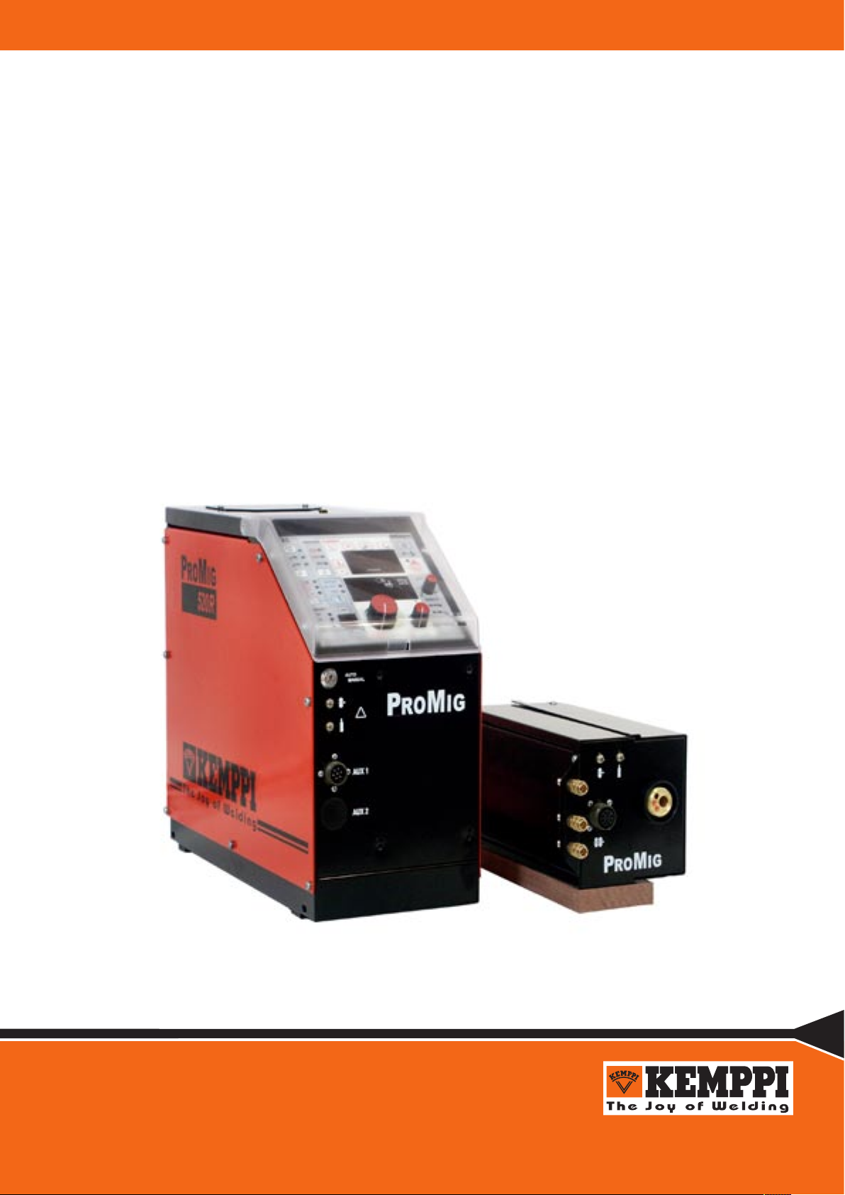
PROMIG
520R, 120R
Page 2

2 – PROMIG 520R, 120R / 0544 © KEMPPI OY
CONTENTS
1. PREFACE ...................................................................................................................... 3
1.1. INTRODUCTION ......................................................................................................... 3
1.2 PRODUCT INTRODUCTION ....................................................................................... 3
1.3. OPERATION SAFETY ................................................................................................. 4
2. INSTALLATION .............................................................................................................. 5
2.1. OPERATION CONTROL AND CONNECTORS .......................................................... 5
2.1.1. PROMIG 520R CONTROL UNIT ................................................................... 5
2.1.2. PROMIG 120R WIRE FEEDER ..................................................................... 6
2.2. UNITS, ACCESSORIES, CABLES .............................................................................. 7
2.3. PARTS OF WIRE FEED MECHANISM ....................................................................... 8
2.4. ASSEMBLY OF MIG SYSTEM .................................................................................... 9
3. INSTALLATION OF MIG SYSTEM .............................................................................. 10
3.1. ACCESSORIES CORRESPONDING TO WIRE DIAMETER .................................... 10
3.2. MOUNTING OF MIG GUN .........................................................................................11
3.3. AUTOMATIC WIRE FEED TO GUN ...........................................................................11
3.4. ADJUSTMENT OF PRESSURE .................................................................................11
3.5. BURN BACK TIME .................................................................................................... 12
3.6. GROUND CABLE ...................................................................................................... 12
3.7. SHIELD GAS ............................................................................................................. 12
3.7.1. INSTALLING GAS BOTTLE ......................................................................... 12
3.8. MAIN SWITCH I/O ..................................................................................................... 13
3.9. OPERATION OF COOLING UNIT ............................................................................ 13
4. CONTROL PANEL OPERATIONS .............................................................................. 13
4.1. MC CONTROL PANEL ............................................................................................. 13
4.1.1. WELD DATA / GAS TEST ............................................................................ 15
4.1.2. SELECTO OPERATIONS, MC PANEL ........................................................ 16
4.2. ML CONTROL PANEL .............................................................................................. 17
4.2.1. WELD DATA ................................................................................................. 20
4.2.2. SYNERGIC OPERATIONS, ML PANEL ....................................................... 21
4.3. MXE CONTROL PANEL ........................................................................................... 23
5. OTHER USER FUNCTIONS ........................................................................................ 24
6. ERROR CODES OF PANELS ..................................................................................... 24
7. SERVICE AND OPERATION DISTURBANCES ......................................................... 25
8. DISPOSAL OF THE MACHINE ................................................................................... 25
9. ORDERING NUMBERS ............................................................................................... 26
11. TERMS OF GUARANTEE ......................................................................................... 28
Page 3

PROMIG 520R, 120R / 0544 – 3© KEMPPI OY
1. PREFACE
1.1. INTRODUCTION
Congratulations on having purchased this product. Properly installed Kemppi products should
prove to be productive machines requiring maintenance at only regular intervals. This manual
is arranged to give you a good understanding of the equipment and its safe operation. It also
contains maintenance information and technical specifications. Read this manual from front to back
before installing, operating or maintaining the equipment for the first time. For further information
on Kemppi products please contact us or your nearest Kemppi distributor.
Specifications and designs presented in this manual are subject to change without prior notice.
In this document, for danger to life or injury the following symbol is used:
Read the warning texts carefully and follow the instructions. Please also study the Operation safety
instructions and respect them when installing, operating and servicing the machine.
1.2 PRODUCT INTRODUCTION
Promig 520R is a welding system designed for robotic and automated welding. It consists of
Promig 520R with inbuilt robot interface and a robot arm mounted feed unit Promig 120R. These
two units are connected with an intermediate cable assembly.
Manual control is possible using interchangeable control panels:
MC: basic controls and displays for MIG welding, Five pre-selectable memory channels.
ML: basic controls and displays for MIG welding, Synergic MIG / Pulsed MIG welding
modes.
MXE: Synergic MIG/MAG and Pulsed MIG in the most demanding welding environment. MMA
welding is also possible.
Welding operation is controlled by microprocessor. The wire feed motor includes an amplified
tachometer feedback system to ensure accurate wire feed speed. The interface stage handles 37
I/O signals covering all automated requirements.
There are three models of PROMIG 520 R. Each model has different versions according to the
robot type.
1) PROMIG 520 R – basic model is to be used with control panels ML and MC.
2) PROMIG 520 R –MXE is designed for use with MXE panel. MXE has 63 memory
channels.
3) PROMIG 520 R –SWF utilises (instead of PROMIG 120 R) an external voltage controlled
wire feeding unit.
Page 4

4 – PROMIG 520R, 120R / 0544 © KEMPPI OY
1.3. OPERATION SAFETY
Please study these Operation safety instructions and respect them when installing, operating and
servicing the machine.
Welding arc and spatters
Welding arc hurts unprotected eyes. Be careful also with reflecting arc flash. Welding arc and
spatter burn unprotected skin. Use safety gloves and protective clothing.
Danger for fire or explosion
Pay attention to fire safety regulations. Remove flammable or explosive materials from
welding place. Always reserve sufficient fire-fighting equipment on welding place. Be prepared
for hazards in special welding jobs, e.g. for the danger of fire or explosion when welding
container type work pieces. Note! Fire can break out from sparks even several hours after the
welding work has been finished!
Mains voltage
Never take welding machine inside a work piece (eg. container or truck). Do not place welding
machine on a wet surface. Always check cables before operating the machine. Change defect cables
without delay. Defect cables may cause an injury or set out a fire. Connection cable must not be
compressed, it must not touch sharp edges or hot work pieces.
Welding power circuit
Isolate yourself by using proper protective clothing, do not wear wet clothing. Never work on a
wet surface or use defect cables. Do not put MIG gun or welding cables on welding machine or
on other electric equipment. Do not press MIG gun’s switch, if the gun is not directed towards a
work piece.
Welding fumes
Take care that there is sufficient ventilation during welding. Take special safety precautions when
welding metals which contain lead, cadmium, zinc, mercury or beryllium.
Page 5
PROMIG 520R, 120R / 0544 – 5© KEMPPI OY
2. INSTALLATION
2.1. OPERATION CONTROL AND CONNECTORS
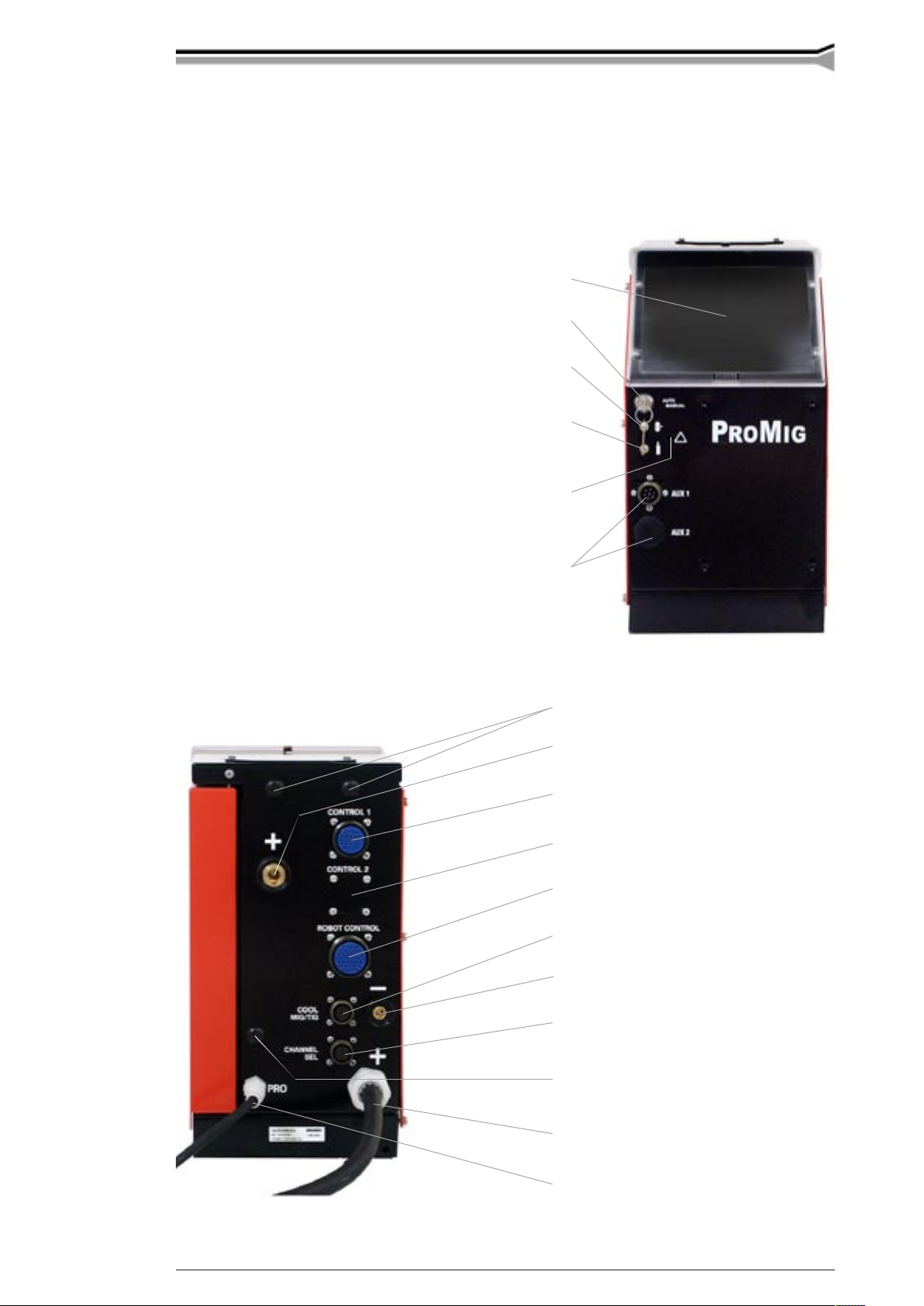
2.1.1. Promig 520R control unit
Place for control panel
Lock switch of panel
(option for MXE model)
Wire inch
Gas purge
Motor overcurrent indicator
Holes for user connectors
Holes for gas snap connectors
Welding current output connector (+)
Control cable connector (to 120R or
voltage controlled wire feeder SWF)
Control cable connector (to 2nd 120R)
Robot controller connector
Control cable connector (Probus)
Voltage monitoring connector (–)
Connector for channel selection
(option for MXE model)
Hole for wire outlet connector
Fixed welding cable to Pro power source
Fixed control cable to Pro power source
Page 6
6 – PROMIG 520R, 120R / 0544 © KEMPPI OY
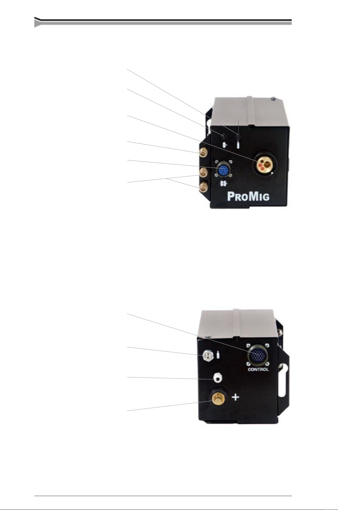
2.1.2. Promig 120R wire feeder
Gas purge
Wire inch
Euro connector for robot gun
Snap connector for air blast
Connector for motorised gun
Snap connectors for
cooling liquid
Control cable connector
Snap connector for gas
Wire liner inlet
Welding current cable connector
Page 7
PROMIG 520R, 120R / 0544 – 7© KEMPPI OY
A
B
C
D
E
F
G
H
I
J
K
L
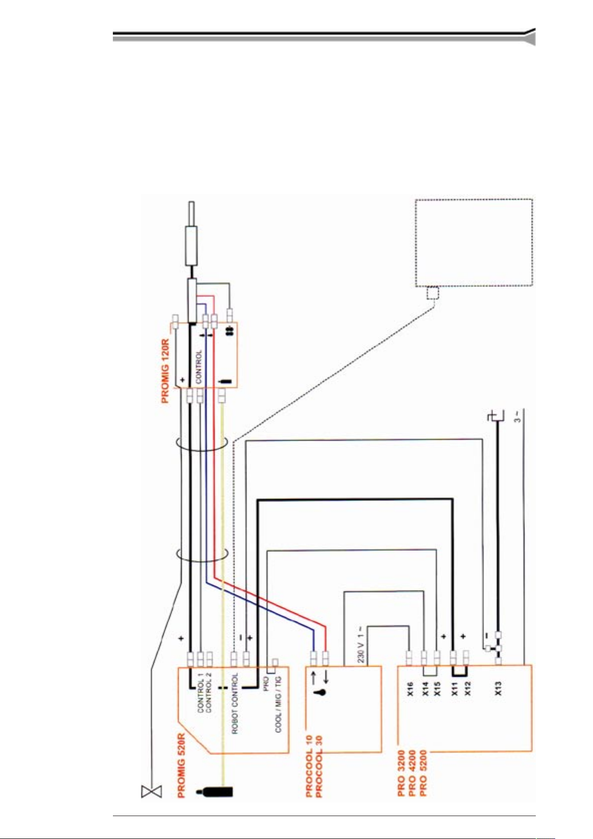
2.2. UNITS, ACCESSORIES, CABLES
A Air hose
B Intermediate cable
assembly
C Air blast
D Shielding gas hose
E Cooling liquid hoses
F Control cable
G Control cable
H Welding current cable
I Voltage monitor cable
J Branch connector
K Earth cable
L Robot control
Page 8
8 – PROMIG 520R, 120R / 0544 © KEMPPI OY
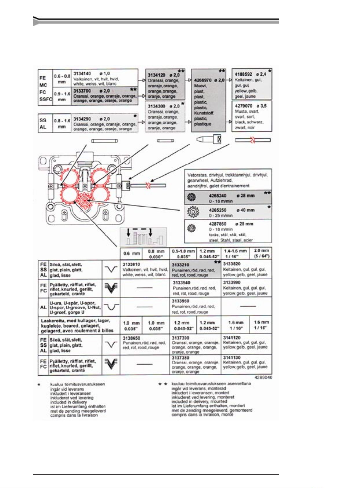
2.3. PARTS OF WIRE FEED MECHANISM
Page 9

PROMIG 520R, 120R / 0544 – 9© KEMPPI OY
2.4. ASSEMBLY OF MIG SYSTEM
Assemble the units according to the mounting instructions delivered with the unit.
1. Installation of power source
Read paragraph “INSTALLATION” in operation instructions for PRO power sources and install
accordingly.
2. Mounting of PRO power source to transport wagon
P 20 see air-cooled MIG system
P 30W see liquid-cooled MIG system
P 40 see air-cooled MIG system
3. Put PROMIG onto the power source and lock it with bolts to handles of power
source.
4. Mounting of PROMIG control panel
MC 6263501 see mounting instructions 4270950
ML 6263502 see mounting instructions 4270950
MXE 6263504 see mounting instructions 4279220
5. Connecting cables
Connect cables according to paragraph ”UNITS, ACCESSORIES, CABLES”.
6. Max. wire feed speed
By delivery, the max. wire feed speed is 18 m/min, which is enough for most welding applications.
If you need a higher speed, you can increase the wire feed speed to 25 m/min by replacing the gear
wheel on motor shaft. The high ratio wheel (*D40*) is delivered with the feed unit.
Changing the maximum wire feed speed:
– Open side plate and remove JUMPER 3 on control card A001. This alters the tacho feedback
ratio to 0 - 25 m/min.
Page 10

10 – PROMIG 520R, 120R / 0544 © KEMPPI OY
20
21 23 24 21
22 25 22
25
– Open tightening lever (20). Remove lower feed rolls (21). Release screw (23) and its washer.
Remove gear wheel D28 (24) from motor shaft.
– Loosen screws (25) (3 pcs) by one twist. Mount D40 gear wheel onto motor shaft. Screw
the screw (23) with its washer back.
– Put feed rolls (21) back on their shafts.
– Lift motor so that tooth gap between gear wheel and both lower feed rolls is approx. 0,2
mm.
– Tighten screws (25). Check gear teeth gaps, if necessary put the motor into a better position.
Screw on mounting screws of feed rolls (22).
Too small a clearance between drive wheel and feed rolls will overload the motor. Too
large a clearance causes rapid wearing of feed rolls’ drive wheel.
3. INSTALLATION OF MIG SYSTEM
3.1. ACCESSORIES CORRESPONDING TO WIRE DIAMETER
PROMIG wire feed rolls are available with plain groove, knurled groove and with U groove.
Feed rolls with plain groove:
Universal feed roll for welding of all kinds of wires.
Feed rolls with knurled groove:
Special feed roll for cored wires and steel wires.
Feed rolls with U groove:
Special feed roll for aluminium wires.
PROMIG wire feed rolls have two grooves. Correct wire groove is selected by moving selecting
washer from over to underneath the feed rolls. Move also drive wheel with the black plastic
washer.
Feed rolls and wire guide tubes of wire feed unit have colour codes to make identification easier.
Page 11

PROMIG 520R, 120R / 0544 – 11© KEMPPI OY
3.2. MOUNTING OF MIG GUN
To ensure trouble-free welding, check in welding gun operating instructions that wire liner and
contact tip are correct for wire feed diameter and wire type. Too tight a wire liner might cause
disturbances in wire feed, and motor overload (this is also a symptom of liner blockage).
Ensure that the welding gun connector is tight.
When you are using liquid-cooled gun, mount water hoses according to the diagram.
Error signal lamp of PROMIG 520R indicates overloading of wire feed motor. Operation of signal
lamp is as follows (also see error codes):
Wire feed motor is slightly overloaded e.g. due to a blocked gun. At a predetermined load the error
signal lamp starts to blink.
If the load is too great the system will shut down (wire feed) and the display panel will indicate
Err 9.
Error code 9, followed by blinking signal lamp is cleared by next start if error condition is no
longer present or motor is not overheated any more.
3.3. AUTOMATIC WIRE FEED TO GUN
Automatic wire feed in PROMIG wire feed units makes changing of wire reel more rapid. When
changing the reel, feed rolls need not be released as the wire will pass directly through.
Groove selecting washer
– Make sure that groove of feed roll matches the diameter of welding wire used. Feed roll groove
is selected by moving the groove selecting washer from top to bottom or vice versa.
– Straighten the wire at a length of about 20 cm and see that its end has no sharp edges (file
off if necessary). A sharp edge may damage the wire guide tube and contact tip of welding
gun.
Automatic feed may sometimes fail with thin wires (Fe, Fc, Ss: 0,6...0,8 mm, Al: 0,8...1,0 mm).
Then you might have to open feed rolls and feed wire manually through feed rolls.
– Feed wire through wire cone until it touches the feed rolls. Do not release pressure of feed
rolls!
– Press wire inch switch and feed wire until wire goes through both sets of rolls.
– Keep inch switch pressed until wire has come through contact tip.
3.4. ADJUSTMENT OF PRESSURE
Adjust feed roll pressure with the control screw (20) so that some resistance may be applied to the
wire without slipping at the feed rolls.
Excessive pressure causes flattening of filler wire and damage to the coating. It also
causes undue wear of feed rolls as well as friction.
Page 12

12 – PROMIG 520R, 120R / 0544 © KEMPPI OY
A
C
G
B
E
D
F
3.5. BURN BACK TIME
The system includes an electronic burn back control which is pre-set.
3.6. GROUND CABLE
Use at least 70 mm2 cables. Thinner cross-sectional areas cause overheating of connectors and
poor Pulsed MIG performance.
Never use a damaged welding gun!
3.7. SHIELD GAS
Handle gas bottle with care. There is a risk for injury if gas bottle or bottle valve is
damaged!
For welding stainless steels, mixed gases are normally used. Check that the gas bottle valve is
suitable for the gas. The flow rate is set according to the welding power used in the job. A suitable
flow rate is normally 8 - 15 l/min. If the gas flow is not suitable, the welded joint will be sporous.
Contact your local Kemppi dealer for choosing gas and equipment.
3.7.1. Installing gas bottle
Always fasten gas bottle properly in vertical position in a special holder on the wall or
on a carriage. Remember to close gas bottle valve after having finished welding.
Parts of gas flow regulator
A Gas bottle valve
B Press regulation screw
C Connecting nut
D Hose spindle
E Jacket nut
F Gas bottle pressure meter
G Gas hose pressure meter
Following installing instructions are valid for most gas flow regulator types:
1. Step aside and open bottle valve (A) for a while to blow out possible impurities.
2. Turn press regulation screw (B) of regulator until no spring pressure can be felt.
3. Close needle valve if there is one in the regulator.
4. Install regulator on bottle valve and tighten connecting nut (C) with a wrench.
5. Install hose spindle (D) and jacket nut (E) into gas hose and tighten with hose clamp.
6. Connect hose with regulator and the other end with wire feed unit. Tighten jacket nut.
Page 13

PROMIG 520R, 120R / 0544 – 13© KEMPPI OY
P21 R21 P22 R22 P23 S22
S21 S24 S25 S26 R23 S23
7. Open bottle valve slowly. Gas bottle pressure meter (F) shows bottle pressure.Note! Do not
use the whole contents of the bottle. Bottle should be filled when bottle pressure is 2 bar.
8. Open needle valve if there is one in the regulator.
9. Turn regulation screw (B) until hose pressure meter (G) shows the required flow (or pressure).
When regulating flow amount, power source should be switched on and gun switch pressed
simultaniously.
Close bottle valve after having finished welding. If the machine will be out of use for a long time,
unscrew pressure regulation screw.
3.8. MAIN SWITCH I/O
When you turn the main switch of PRO power source into position I, pilot lamp next to it is lit and
the equipment is ready for welding. The equipment reverts to the welding method used before the
main switch was turned to position zero.
Always start and switch off the machine with the main switch, never use the mains
plug as a switch.
3.9. OPERATION OF COOLING UNIT
(PROCOOL 10, procool 30)
Operation of cooling unit is controlled so that pump is turned on when welding is started. After
welding stop pump is rotating for approx. 5 min, thus cooling the liquid to ambient temperature.
Read in operation instructions for cooling unit the trouble situations in liquid circulation system
and protection against damage of gun etc.
4. CONTROL PANEL OPERATIONS
4.1. MC CONTROL PANEL
Page 14

14 – PROMIG 520R, 120R / 0544 © KEMPPI OY
MIG basic operations
Welding method selection (S21): no function
Control mode selection (S22): local, remote by robot controller
Local controls: wire feed speed (R21), welding voltage (R22)
Controls for MIG welding dynamics (R23)
Digital displays: wire feed speed (P21), current (P22), voltage (P23)
Retrieval of last weld values (S23)
SELECTO operations
SELECTO mode switch S24
OFF: Normal MIG/MAG welding
ON: Welding with memory stored values (5 channels)
SET: Welding parameters selection and storage SAVE (S25), for selected channel CHANNEL
1...5 (S26).
Welding method selecting switch S21
No function: always two-sequence procedure
MIG/MAG welding with two-sequence procedure
1. start on: welding starts
2. start off: welding stops
Control mode selecting switch S22
Local control: Control potentiometers R21 and R22 on panel are operational.
Remote control: Voltage and wire feed speed set values controlled by robot
controller
(Switch center = remote position)
Local controls R21, R22
Wire feed speed potentiometer
SELECTO OFF: Local control for wire feed speed 0...18
m/min or 0...25 m/min
SELECTO ON: No operation
SELECTO SET: Local control for wire feed speed 0...18
m/min or 0...25 m/min
Voltage potentiometer
SELECTO OFF: Local control for voltage of PRO power
source, 10 V...max. MIG voltage of power source
SELECTO ON: No operation
SELECTO SET: Local control for voltage of PRO power
source, 10 V...max. MIG voltage of power source
Page 15

PROMIG 520R, 120R / 0544 – 15© KEMPPI OY
Control of welding dynamics R23
When you adjust welding dynamics, adjustment value -9...0...9 is shown momentarily in the Voltage display which normally shows set value / welding voltage. Value
of dynamics is shown in display for approx. 3 s after adjustment.
Control of MIG welding dynamics:
With MIG welding dynamics control you can influence arc stability.
-9...-1 Softer arc decreasing spatter
0 Default setting for all wires
1...9 Harder arc maximising stability of arc during short circuit and welding of steel with 100 %
CO2 shield gas (settings 7...9).
Digital display for wire feed speed, current and voltage P21, P22, P23
/ m / min display
Display shows set value of wire feed speed switching to true value 0.0...18.0 m/min or 0.0...25.0
m/min during welding.
A display
Display shows 0 A (*no welding*) switching to true value of welding current during welding.
V display
Display shows set value of welding voltage and true value during welding.
Note! Display shows terminal voltage of power source. Depending on length and copper cross-
section of welding cables real arc voltage and display may differ. See table below.
Cable 50 mm2 70 mm2 95 mm2
Voltage loss/10 m 0,35 V/100 A 0,25 V/100 A 0,18 V/100 A
4.1.1. WELD DATA / GAS TEST
Retrieval of welding parameters to displays
Use of WELD DATA switch retrieves welding parameters, wire feed speed, welding
current, welding voltage which were used when welding was stopped last. Welding
values are indicated in display for so long you are using the WELD DATA switch,
and are stored until you press again the start switch for gun.
Testing the gas flow
A short press on switch starts flow of shielding gas. The shielding gas flows for approximately 20
seconds, or until the switch is pressed again.
Page 16

16 – PROMIG 520R, 120R / 0544 © KEMPPI OY
4.1.2. SELECTO operations, MC panel
SELECTO is the name for the operation which allows you to store welding parameters. You can
save five sets of MIG welding values. Parameters which can be stored are wire feed speed, welding
voltage and welding dynamics.
In SELECTO operations there are three different operating modes:
SELECTO OFF: Normal MIG welding with independent adjustments for wire feed speed and
voltage, SELECTO functions are not in use.
SELECTO ON: Welding with stored welding values, wire feed speed, welding voltage and welding
dynamics. Only the channel selection switch is operational. Channels are selected according to the
position of the local remote switch. Channels may be switched either with the CHANNEL switch
or through the interface connector by the robot. You can change channels during welding.
Digital display indicates values for wire feed speed and voltage which are stored on the channel in
question. The stored value for welding dynamics can be retrieved by moving the welding dynamics
potentiometer.
SELECTO SET: Settings are stored for indicated channel by using the SAVE switch. The values
currently set for wire feed speed, voltage and welding dynamics are stored in that memory
location.
Programming of memory channel:
1. Select channel 1...5.
2. Set SELECTO mode switch to SET.
3. Find correct values for wire feed speed, voltage and welding dynamics.
4. Store them by using the SAVE switch.
Note! You can check data which you have stored in memory by setting SELECTO mode
switch on position ON, the display will show the values stored in that memory location.
5. Set SELECTO mode switch to position ON and pre-set channels are active.
Page 17

PROMIG 520R, 120R / 0544 – 17© KEMPPI OY
MIG
1-MIG
S32P33R32P32R31P31
S31 S34 S35 S36 R34 R33 S33
4.2. ML CONTROL PANEL
MIG basic operations
Welding method selection (S31): no function
Control mode selection (S32): local, remote
Local controls: wire feed speed/welding power/(R31), welding voltage (R32)
Controls for MIG welding dynamics (R33)
Digital displays: wire feed speed (P31), current (P32), voltage (P33)
Retrieval of last actual welding values (S33)
SYNERGIC operations
SYNERGIC mode switch S34
Normal MIG welding with independent adjustments for wire feed speed (R31)
and voltage (R32).
SYNERGIC MIG: MIG welding with parameters which are pre-set according
to filler wire (S35, S36). Welding parameters are adjusted with adjustment
potentiometers for welding power (R31) and arc length (R32).
SYNERGIC PULSEMIG: Pulsed MIG welding with parameters which are pre-set
according to filler wire (S35, S36). Welding parameters are adjusted with adjustment
potentiometers for welding power (R31) and arc length (R32).
Gun cable length compensation (R34)
Page 18

18 – PROMIG 520R, 120R / 0544 © KEMPPI OY
Welding method selecting switch S31
No function: always two-sequence procedure
MIG welding with two-sequence procedure
1. switch pressed: welding starts
2. switch open: welding stops
Control mode selecting switch S32
Local control: Control potentiometers R31 and R32
Remote control: Voltage and wire feed speed set values from robot controller
(gun control = remote position)
Local controls R31, R32
Wire feed speed potentiometer
MIG/MAG: Local control for wire feed speed 0...18 m/min or 0...25 m/min
SYNERGIC MIG: Power control
SYNERGIC PULSED MIG: Power control
Voltage / arc length potentiometer
MIG local control for PRO power source welding voltage, 10 V...max MIG voltage of power
source
SYNERGIC MIG: Fine control for arc length, shows voltage which has been programmed in
proportion to wire feed value. Voltage control range depends on wire feed value.
SYNERGIG PULSED MIG: Fine control for arc length -9...0...9
Control of welding dynamics R33
When you adjust welding dynamics, the adjustment value -9...0...9 is shown in
display V, which otherwise shows set value / welding voltage. Value of dynamics
is shown in display for approx. 3 s after adjustment.
Page 19

PROMIG 520R, 120R / 0544 – 19© KEMPPI OY
Control of MIG/MAG welding dynamics:
With the MIG welding dynamic control you can influence arc stability.
-9...-1 Softer arc. Object: minimising spatter
0 Recommendable basic setting for all wires
1...9 Harder arc. Object: e.g. maximising stability of the arc on short circuit and welding of
steel with 100 % CO2 shielding gas (settings 7...9).
Control of SYNERGIC MIG welding dynamics:
In SYNERGIC MIG the control of welding dynamics is optimised for wire type you are using.
With this control you can influence stability of arc and amount of spatter.
-9...-1 Softer arc. Object: Minimising spatter
0 Recommended default setting
1...9 Harder arc. Object: e.g. maximising stability of the arc on short circuit
NOTE! Control range for MIG welding dynamics -9...0...9 is a relative range according to wire
and is different from control range -9...0...9 for dynamics of normal MIG/MAG welding.
Shape of arc in SYNERGIC PULSED MIG:
In SYNERGIC PULSED MIG control for welding dynamics has an influence on shape of pulsed
MIG arc.
-9...-1 Wider pulsed MIG arc. Object: e.g. welding of square butt preparation
0 Recommended basic setting
1...9 Narrow focussed arc. Object: e.g. fillet welds
Digital display for wire feed speed, current and voltage P31, P32, P33
/ m / min display
MIG/MAG with independent controls for wire feed speed and voltage: Display shows set value
for wire feed speed and true value 0.0...18.0 m/min or 0.0...25.0 m /min during welding depending
on selection of wire feed speed range.
SYNERGIC MIG welding: Display shows set value for wire feed speed and true value during
welding.
Wire feed speed min. and max speed.
SYNERGIC PULSED MIG welding: Display shows set value for wire feed speed and true value
during welding.
Wire feed speed range depends on wire type min. and max. speed.
Page 20

20 – PROMIG 520R, 120R / 0544 © KEMPPI OY
I / A display
MIG/MAG welding with independent controls for wire feed speed and voltage: Display shows 0
A before, and true value during welding.
SYNERGIC MIG welding: Display shows 0 A before, and true value during welding.
SYNERGIC PULSED MIG welding: Display shows in setting state the reference mean current
value, and true value for welding current during welding.
U / V display
MIG/MAG welding with independent adjustments for wire feed speed and voltage: Display shows
pre-set value for welding voltage, and true value during welding.
SYNERGIC MIG welding: Display shows pre-set value for welding voltage, and true value during
welding.
When adjusting arch length display shows voltage.
SYNERGIC PULSED MIG welding: In setting state, display shows set value -9...0...9 for arc
length, and true value of welding voltage during welding.
Note! Display shows terminal voltage of power source. Depending on length and copper cross-
section of welding cables real arc voltage and display may differ (see table below).
Cable 50 mm2 70 mm2 95 mm2
Voltage loss/10 m 0,35 V/100 A 0,25 V/100 A 0,18 V/100 A
When you adjust welding dynamics, display V shows adjustment value for welding dynamics
-9...0...9, the value is shown for approx. 3 s after end of adjustment. After that display reverts to
show voltage in SYNERGIC MIG and arc length in SYNERGIC PULSED MIG welding.
4.2.1. WELD DATA
Retrieval of welding parameters to displays
Use of WELD DATA switch retrieves welding parameters, wire feed speed, welding current,
welding voltage which were used when welding was stopped last. Welding values are indicated
in display for so long you are using the WELD DATA switch and are stored until you press again
the start switch of gun.
Testing the gas flow
A short press on the switch starts shielding gas flow. Shielding gas flows for approximately 20
seconds, or until the switch is pressed again.
Page 21

PROMIG 520R, 120R / 0544 – 21© KEMPPI OY
MIG
1-MIG
4.2.2. SYNERGIC operations, ML panel
In SYNERGIC operation, the welder indicates the filler wire type and diameter to be used.
The equipment then generates optimal welding settings. In SYNERGIC mode the wire feed
potentiometer changes the adjustment for welding power, voltage and dynamics automatically (so
called “one knob adjustment”).
In SYNERGIC operation there are three operation modes:
Normal MIG/MAG welding with independent adjustments for wire feed speed
and voltage.
SYNERGIC operation is not active.
SYNERGIC MIG welding with parameters which are optimised according to
filler wire parameters. Nine SYNERGIC MIG programs for different filler wires
are stored:
Diameter Filler wire Shielding gas
Welding of steel (Fe)
ø 1,0 mm Fe solid wire Ar + 18 % CO
²
ø 1,2 mm Fe solid wire Ar + 18 % CO
²
ø 1,2 mm Mc cored wire Ar + 18 % CO
²
Welding of stainless steel (Ss)
ø 0,8 mm Ss solid wire Ar + 2 % CO
²
ø 1,0 mm Ss solid wire Ar + 2 % CO
²
ø 1,2 mm Ss solid wire Ar + 2 % CO
²
Welding of aluminium (Al)
ø 1,0 mm AlMg5, *)AlSi5 Ar
ø 1,2 mm AlMg5, *)AlSi5 Ar
ø 1,6 mm AlMg5, *)AlSi5 Ar
In SYNERGIC MIG welding the welding values are adjusted with power potentiometer
(normally potentiometer for wire feed speed), arc length potentiometers (normally voltage
potentiometer) and welding dynamics potentiometer. Min. and max. power optimised for each
wire correspond to min. and max. setting of power adjustment potentiometer.
*) Comes to use with a jumper.
Page 22

22 – PROMIG 520R, 120R / 0544 © KEMPPI OY
Compensating cable length
Cable length compensation allows the operator to overcome voltage losses which are caused by
long interconnecting cables. Cable compensation is adjusted as follows:
If interconnecting cables between wire feed unit and power
source are not used, set cable compensation at position
zero.
If the zero position does not operate as you want it to, make
adjustment check as described in the following.
When using interconnecting cables, do as follows:
1. Adjust arc length at = CALIB, which corresponds to normal arc length.
2. Weld at power level required.
3. Adjust cable compensation potentiometer to give suitable arc length.
4. Check adjustment range for arc length by adjusting arc length -9...0...9.
5. When needed repeat points 2...4.
Cable compensation is adjusted for each cable / MIG welding gun combination only once.
Synergic pulsed MIG, pulsed MIG welding with parameters which are optimised
according to filler wire parameters. Nine SYNERGIC PULSED MIG programs
for different filler wires are stored:
Diameter Filler wire Shielding gas
Pulsed MIG welding of steel (Fe)
ø 1,0 mm solid wire Ar + 18 CO
²
ø 1,2 mm solid wire Ar + 18 CO
²
ø 1,2 mm metal cored wire Ar + 18 CO
²
Pulsed MIG welding of stainless steel (Ss)
ø 0,8 mm solid wire Ar + 2 % CO
²
ø 1,0 mm solid wire Ar + 2 % CO
²
ø 1,2 mm solid wire Ar + 2 % CO
²
Pulsed MIG welding of aluminium (Al)
ø 1,0 mm AlMg5 Ar
ø 1,2 mm AlMg5 Ar
ø 1,6 mm AlMg5 Ar
Page 23

PROMIG 520R, 120R / 0544 – 23© KEMPPI OY
In SYNERGIC PULSED MIG welding, welding values are adjusted with power potentiometer
(normally potentiometer for wire feed speed), arc length potentiometer (normally voltage
potentiometer) and welding dynamics potentiometer. Min. and max. power is optimised for each
wire type and corresponds to min. and max setting of power adjustment potentiometer.
Compensating cable length
See paragraph “SYNERGIC MIG welding”.
4.3. MXE CONTROL PANEL
Operations of MXE control panel are described in manual delivered with MXE.
Exceptions to the operations of MXE in robot use:
- 4T start switch function is not active
- gun remote control is not active
- there are 63 active memory channels
Other functions related to robot use:
MXE panel can be used in normal local control by setting MEMORY OFF and LOCAL. Key
switch on machine front is turned to position MANUAL. All adjustments are set with the panel.
In this case start and stop of machine can be controlled with robot.
By setting MXE panel to REMOTE mode, wire feed speed/voltage or power/fine control can be
regulated with robot via analog lines.
Memory channels can be programmed as described in the operating manual of MXE panel.
When retrieving memory channels, you can choose with robot whether to use wire feed speed/
voltage or power/fine control values retrieved from memory, or whether these values are controlled
with robot via analog lines (see technical manual).
When controlling memory channels with robot, memory functions are to be set to MEMORY ON
mode. Key switch is turned to position AUTO.
Note! On memory channel 0 (= no memory channel selected) machine always retrieves memory
channel which was used last.
Page 24

24 – PROMIG 520R, 120R / 0544 © KEMPPI OY
5. OTHER USER FUNCTIONS
Selection between gas-cooled and water-cooled gun is made using the switch inside the control
unit.
Wire inch switch function is in the front of control unit and feeder unit.
– displays main motor current on welding current window and gun motor current on voltage
display window
– inch speed is set by local control setting (panel)
Gas purge switch is in the front of control unit and feeder unit.
– gas purge when pressed
Gas valve is mounted inside the feeder unit but it can also be moved into the control unit where
there is a place for it.
A gas pressure switch can be mounted inside the control unit.
Inside the control unit there is a 20 kg mig wire spool system.
6. ERROR CODES OF PANELS
Error codes inform the user about welding system malfunctions. They are displayed on MC/ML
panels.
Err 1: Robot identification failed. Robot identification is done using XW114 on A003 X8.
Err 2: Power source has been started for MMA or TIG mode.
Err 3: Same as Err 2 but up (+) / down (–) buttons are active on PX panel (optional).
Err 4: Cooling unit (Procool 10 / 30) is not starting (check gas/water switch).
Err 5: Cooling unit (Procool 10 / 30) has a cooling failure (overheating sensor or pressure switch
has reacted or unit is missing supply voltage).
Err 6: Water unit (Procool 10 / 30) has been started normally, but wire feed unit (Promig 520R)
has lost serial communication link to cooling unit (check interconns).
Err 7: Emergency stop is active. Input relay K2 must be active on A003 to cancel emergency stop
(only Promig 520R - KU).
Err 9: Overload of wire feed motor which may be caused by blocked wire guide of gun or by gun
cable which is too curved.
Err 10: PRO power supply reports error when start message from Promig 520R is sent. Operation
of thermal protection of PRO power source has stopped welding.
Err 14: Supply overvoltage in Promig 520R.
Error code display is cleared by next start if the cause of error code has been eliminated.
Page 25

PROMIG 520R, 120R / 0544 – 25© KEMPPI OY
7. SERVICE AND OPERATION DISTURBANCES
The amount of use and working environment should be taken into consideration when planning
the frequency of maintenance of PROMIG. Careful use and preventive maintenance will help to
ensure trouble-free operation.
Following maintenance operations should be carried out at least every six months:
Check:
– Feed roll grooves. Excessive wear of grooves causes
wire feed problems.
– Wire guide tubes. Badly worn feed rolls and wire guide
tubes should be discarded.
– Wire guide tube in the gun should be set as near the feed
rolls as possible and the wire must follow a straight line
from the end of the tube to the groove of the feed roll.
– Reel brake adjustment.
– Electrical connections:
* Oxidized couplings must be cleaned
* Loose couplings must be tightened
Clean dust and dirt from the equipment.
When using compressed air, always protect your eyes with proper eye protection.
In case of problems contact your KEMPPI dealer.
8. DISPOSAL OF THE MACHINE
Do not dispose of electrical equipment together with normal waste!
In observance of European Directive 2002/96/EC on Waste Electrical and Electronic
Equipment and its implementation in accordance with national law, electrical equipment
that has reached the end of its life must be collected separately and returned to an
environmentally compatible recycling facility. As the owner of the equipment, you should
get information on approved collection systems from our local representative.
By applying this European Directive you will improve the environment and human
health!
twice a year
Page 26

26 – PROMIG 520R, 120R / 0544 © KEMPPI OY
9. ORDERING NUMBERS
Wire feed units
Promig 520R wire feed control unit 6231510
Promig 120R wire feed unit 6236320
Accessories of Promig 520R
MC function panel 6263501
ML function panel 6263502
MXE function panel 6263504
Prosync 50 synchronisation set 6263121
Voltage sensor 4289560
Current sensor 4288790
Wire reel hub 4289880
Power sources
Kemppi Pro Evolution 3200 6131320
Kemppi Pro Evolution 4200 6131420
Kemppi Pro Evolution 5200 6131520
Cooling unit
PROCOOL 10 6262012
PROCOOL 30 6262016
Cabels
Voltage monitor cable 4288700
Branch connector 9771637
Intermediate cable assembly 5 m 6260421
10 m 6260425
Earth cable 50 mm2 5 m 6184511
50 mm2 10 m 6184512
Earth cable 70 mm2 5 m 6184711
70 mm2 10 m 6184712
MIG guns for robotic and automated welding
MT-51MW 1,5 m / SK 6255156
MT-51MW 1,5 m / K30 6255157
MT-51MW 3,0 m / SK 6255158
MT-51MW 3,0 m / K30 6255159
Transport wagons
P 20 6185261
P 30W 6185262
P 40 6185264
Page 27

PROMIG 520R, 120R / 0544 – 27© KEMPPI OY
10. TECHNICAL DATA
Promig 520R, Promig 120R
Operating voltage (safety voltage) 50 V DC
Rated power 100 W
Max. load 60 % ED 500 A
(nominal values) 100 % ED 390 A
Operation principle 4-roll feed
Diameter of feed roll 32 mm
Wire feed speed I 0...18 m/min
II 0...25 m/min
Filler wires ø Fe, Ss 0,6...2,4 mm
ø Cored wires 0,8...2,4 mm
ø Al 1,0...2,4 mm
Wire reel max. weight 20 kg
max. size ø 300 mm
Gun connector Euro
Operation temperature range -20...+40 oC
Storage temperature range -40...+60 oC
Degree of protection IP 23
Promig 520R
Dimensions (without handle)
length 620 mm
width 230 mm
height 480 mm
weight 20 kg
Promig 120R
Dimensions length 319 mm
width 152 mm
height 167 mm
weight 8 kg
The products meet conformity requirements for CE marking.
Page 28

28 – PROMIG 520R, 120R / 0544 © KEMPPI OY
11. TERMS OF GUARANTEE
Kemppi Oy provides a guarantee for products manufactured and sold by them if defects in
manufacture and materials occur. Guarantee repairs must be carried out only by an Authorised
Kemppi Service Agent. Packing, freight and insurance costs to be paid by orderer. The guarantee is
effected on the date of purchase. Verbal promises which do not comply with the terms of guarantee
are not binding on guarantor.
Limitations on guarantee
The following conditions are not covered under the terms of guarantee: defects due to natural wear
and tear, non-compliance with operating and maintenance instructions, connection to incorrect or
faulty supply voltage (including voltage surges outside equipment spec.), incorrect gas pressure,
overloading, transport or storage damage, fire of damage due to natural causes i.e. lightning or
flooding.
This guarantee does not cover direct or indirect travelling costs, daily allowances or accommodation.
Note: Under the terms of guarantee, welding torches and their consumables, feeder drive rolls and
feeder guide tubes are not covered. Direct or indirect damage due to a defective product is not
covered under the guarantee. The guarantee is void if changes are made to the product without
approval of the manufacturer, or if repairs are carried out using non-approved spare parts.
The guarantee is also void if repairs are carried out by non-authorised agents.
Undertaking guarantee repairs
Guarantee defects must be informed to Kemppi or authorised Kemppi Service Agents within the
guarantee period. Before any guarantee work is undertaken, the customer must provide proof of
guarantee or proof of purchase, and serial number of the equipment in order to validate the guarantee.
The parts replaced under the terns of guarantee remain the property of Kemppi.
Following the guarantee repair, the guarantee of the machine or equipment, repaired or replaced,
will be continued to the end of the original guarantee period.
Page 29

KEMPPI OY
PL 13
FIN – 15801 LAHTI
FINLAND
Tel (03) 899 11
Telefax (03) 899 428
www.kemppi.com
KEMPPIKONEET OY
PL 13
FIN – 15801 LAHTI
FINLAND
Tel (03) 899 11
Telefax (03) 7348 398
e-mail: myynti.fi @kemppi.com
KEMPPI SVERIGE AB
Box 717
S – 194 27 UPPLANDS VÄSBY
SVERIGE
Tel (08) 590 783 00
Telefax (08) 590 823 94
e-mail: sales.se@kemppi.com
KEMPPI NORGE A/S
Postboks 2151, Postterminalen
N – 3103 TØNSBERG
NORGE
Tel 33 34 60 00
Telefax 33 34 60 10
e-mail: sales.no@kemppi.com
KEMPPI DANMARK A/S
Literbuen 11
DK – 2740 SKOVLUNDE
DANMARK
Tel 44 941 677
Telefax 44 941 536
e-mail:sales.dk@kemppi.com
KEMPPI BENELUX B.V.
Postbus 5603
NL – 4801 EA BREDA
NEDERLAND
Tel +31 (0)76-5717750
Telefax +31 (0)76-5716345
e-mail: sales.nl@kemppi.com
KEMPPI (UK) Ltd
Martti Kemppi Building
Fraser Road
Priory Business Park
BEDFORD, MK443WH
ENGLAND
Tel 0845 6444201
Fax 0845 6444202
e-mail: sales.uk@kemppi.com
KEMPPI FRANCE S.A.
65 Avenue de la Couronne des Prés
78681 EPONE CEDEX
FRANCE
Tel (01) 30 90 04 40
Telefax (01) 30 90 04 45
e-mail: sales.fr@kemppi.com
KEMPPI GmbH
Otto – Hahn – Straße 14
D – 35510 BUTZBACH
DEUTSCHLAND
Tel (06033) 88 020
Telefax (06033) 72 528
e-mail:sales.de@kemppi.com
KEMPPI SP. z o.o.
Ul. Piłsudskiego 2
05-091 ZA¸BKI
Poland
Tel +48 22 781 6162
Telefax +48 22 781 6505
e-mail: info.pl@kemppi.com
KEMPPI WELDING
MACHINES AUSTRALIA PTY LTD
P.O. Box 404 (2/58 Lancaster Street)
Ingleburn NSW 2565, Australia
Tel. +61-2-9605 9500
Telefax +61-2-9605 5999
e-mail: info.au@kemppi.com
Ver. 9
www.kemppi.com
 Loading...