

Page 1
Kemppi pRO eVOLUTiON
3200, 4200, 5200
Kemppi pRO eVOLUTiON
3200 mVU, 4200 mVU, 5200 mVU
1913130E
0617
Page 2

2 – Kemppi pro evolution 3200, 4200, 5200, 3200 mvu, 4200 mvu, 5200 mvu / 0617 © Kemppi oy
contents
1. preface ........................................................................................................................ 3
1.1. Introduction .......................................................................................................................3
1.2. Product introduction ..........................................................................................................
3
1.2.1. Operation control and connectors ................................................................................... 4
1.3. Accessories ....................................................................................................................... 5
1.3.1. Remote control devices ................................................................................................... 5
1.3.2. Control panels .................................................................................................................
5
1.3.3. Cables ............................................................................................................................. 6
1.4. Operation safety ................................................................................................................ 6
2. InstallatIon ............................................................................................................... 7
2.1. Siting the machine and mounting the control panels PL and PX ...................................... 7
2.2.1. Connection to the mains supply ...................................................................................... 7
2.2.2. Welding and earth cables ................................................................................................
8
3. operatIon control swItches and potentIometers and theIr use ..... 8
3.1. Main switch I/O ..................................................................................................................8
3.2. Pilot lamps .........................................................................................................................
9
3.3. Local or remote control of welding current ........................................................................
9
3.4. Operation of cooling fan ....................................................................................................
9
4. accessorIes ............................................................................................................... 9
4.1. PL and PX control panels’ operation in MMA welding ....................................................... 9
4.1.1. Control for MMA welding dynamics (PL, PX) .................................................................. 9
4.1.2. Control of ignition pulse current (PX) ............................................................................
10
4.1.3. Meter display (PL, PX) ..................................................................................................
10
4.1.4. Operation mede selection (PX) .....................................................................................
10
5. coolIng unIt supply .............................................................................................. 11
6. maIntenance ............................................................................................................
11
6.1. Cables ............................................................................................................................. 11
6.2. Power source ..................................................................................................................
12
6.3. Regular maintenance ......................................................................................................
12
7. operatIon dIsturbances .................................................................................... 12
7.1. Operation of the overload protection ............................................................................... 12
7.2. Control fuses ...................................................................................................................
12
7.3. Under- and overvoltages in the mains supply .................................................................
13
7.4. Loss of a phase in the mains supply ...............................................................................
13
7.5. Disposal of the machine ..................................................................................................
13
8. orderIng numbers ................................................................................................13
9. technIcal data .......................................................................................................
14
10. terms of guarantee .............................................................................................
15
Page 3
Kemppi pro evolution 3200, 4200, 5200, 3200 mvu, 4200 mvu, 5200 mvu / 0617 – 3© Kemppi oy
1. preface
1.1. IntroductIon
Congratulations on having purchased this product. Properly installed Kemppi products should
prove to be productive machines requiring maintenance at only regular intervals. This manual
is arranged to give you a good understanding of the equipment and its safe operation. It also
contains maintenance information and technical specications. Read this manual from front to
back before installing, operating or maintaining the equipment for the rst time. For further
information on Kemppi products please contact us or your nearest Kemppi distributor.
The specications and designs presented in this manual are subject to change without prior
notice.
In this document, for danger to life or injury the following symbol is used:
Read the warning texts carefully and follow the instructions. Please also study the Operation
safety instructions and respect them when installing, operating and servicing the machine.
1.2. product IntroductIon
Kemppi Pro Evolution 3200, 4200 and 5200 are multi-operator power sources designed for
demanding professional use. They are suitable for MMA/MIG and pulsed MIG as well as for
TIG welding in DC. Kemppi Pro Evolution can be used as power source with a welding auto-
mate or robot.
Power control of Kemppi Pro Evolution power source has been realized with at approx. 20 kHz
frequency IGBT transistors operating and control unit with microprosessor.
Kemppi Pro machines can be seen in operating instructions for each unit. Mounting intructions
for control panels PX and PL are in their packages.
This manual handles installation and use of Kemppi Pro Evolution power sources.
This equipment’s electromagnetic compatibility (EMC) is designed for use in an
industrial environment. Class A equipment is not intended for use in residential loca-
tion where the electrical power is provided by the public low-voltage supply system.
Page 4
4 – Kemppi pro evolution 3200, 4200, 5200, 3200 mvu, 4200 mvu, 5200 mvu / 0617 © Kemppi oy
H12
S11
X14
01
F11
X16
F12
S11
H11
H12
01
F11
X14
X12
X13
X15
X11
X12
X13
X11
H11
X15
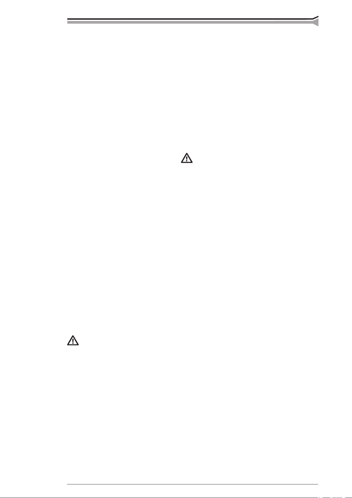
1.2.1. Operation control and connectors
F11 Fuse for connetion for control table 6,3 A delayed
H11 Signal lamp I/O
H12 Warning lamp for thermal protection
S11 Main switch I/O
X11, Welding connection parallel
X12
X13 Earth connection
X14, Connection for control cable parallel
X15
01 Inlet of mains cable
02 Inspection cover for control panel PL, PX Accessories
X16 Socket outlet Fuse 230 V, 250 VA
F12 Fuse for socket outlet 1,0 A delayed
pro evolutIon
pro evolutIon mvu
Page 5
Kemppi pro evolution 3200, 4200, 5200, 3200 mvu, 4200 mvu, 5200 mvu / 0617 – 5© Kemppi oy
R61
R61
R63
P21
P22 P23 R22
R21 S21
P31 P32 P33 H31
H32
S33 S34 S35 S36
S37
S31
S32
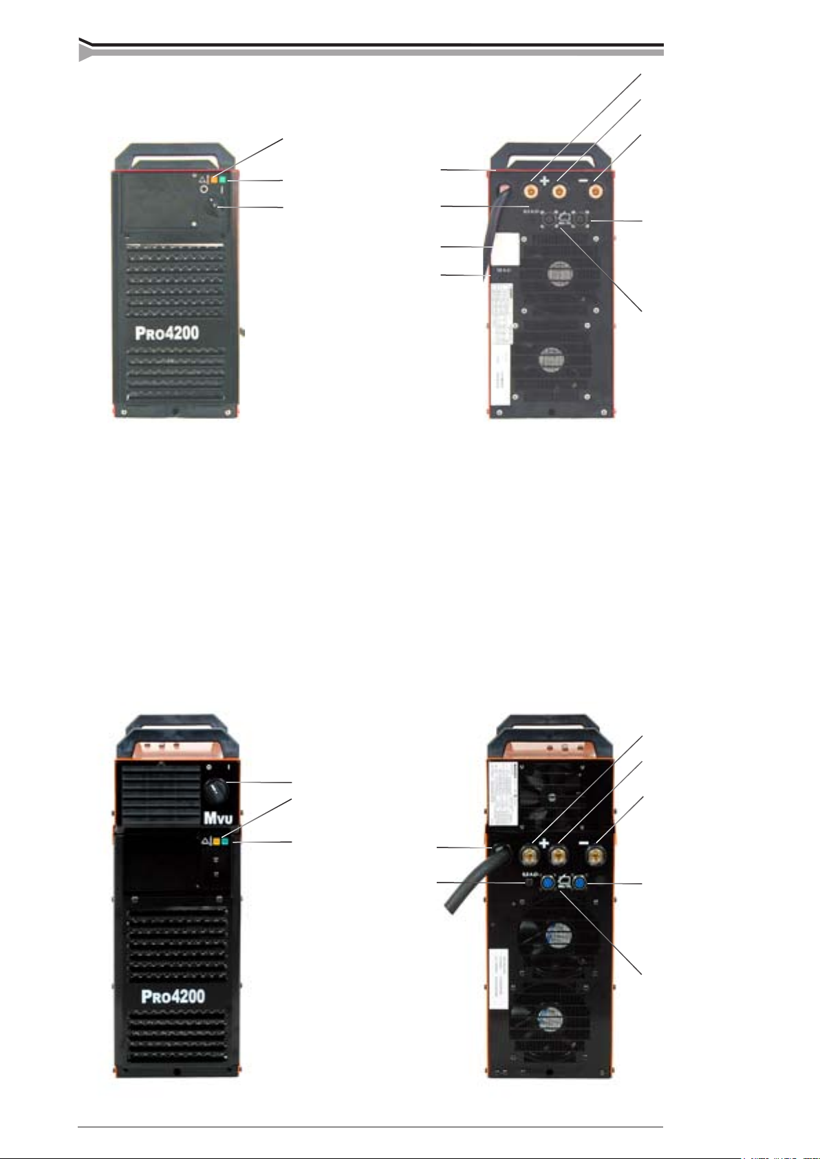
1.3. accessorIes
Control of MMA/TIG welding current (R61), reference scale 1 … 10.
R20 6185419
MIG-MAG remote control device with controls for wire feed (R63) and voltage (R61), memory
scales 1 … 10.
You can use control device also for control of MMA current from potentiometer R63.
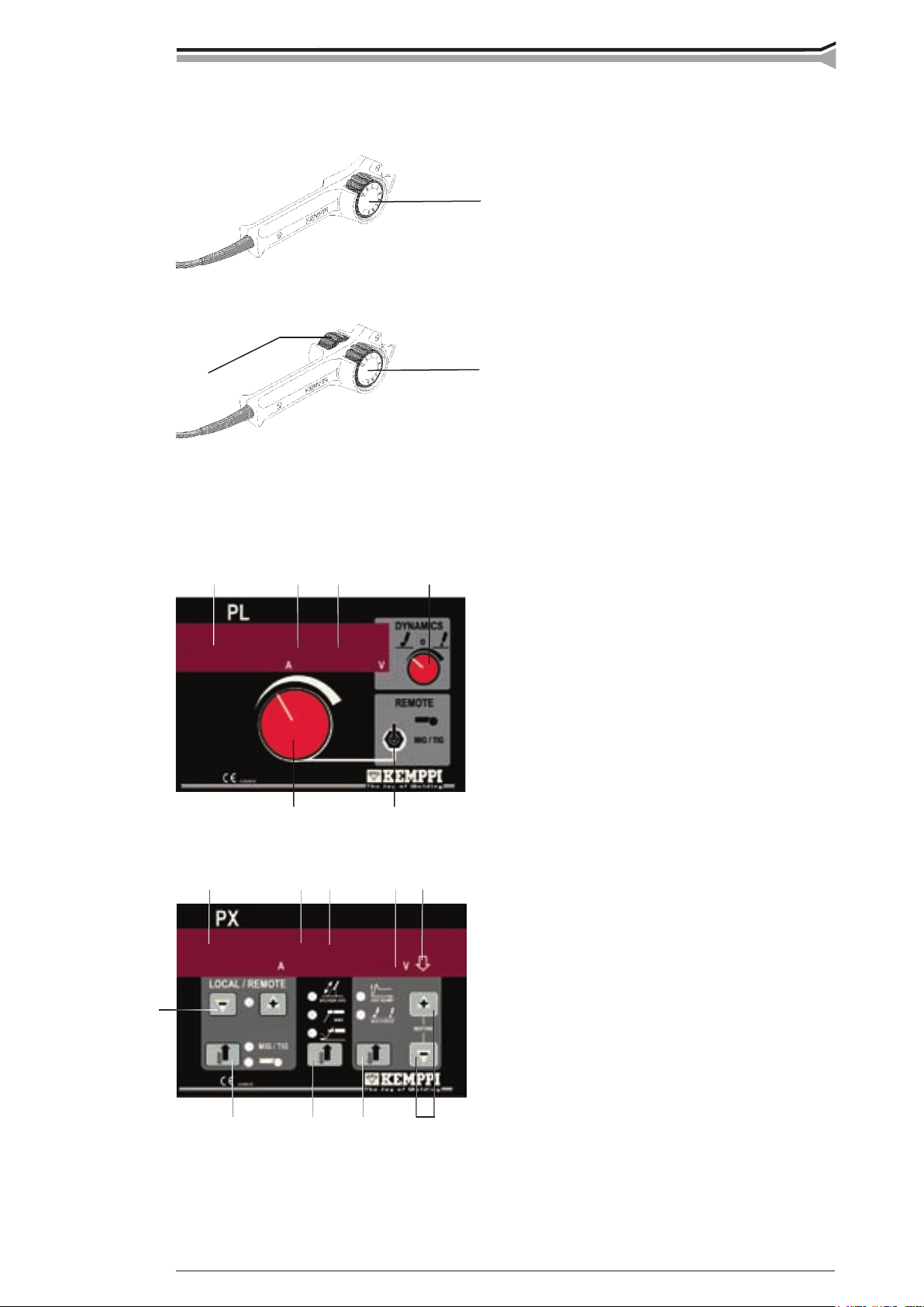
1.3.2. Control panels
PL panel 6185801
P21 Current meter
set value / welding current
P22 Voltage meter
open circuit / terminal voltage
P23 Display for adjustment value of MMA
welding dynamics -9 … 0 …+9
R21 Adjustment of welding current
R22 Adjustment of MMA welding dynamics
S21 Selection for local / remote control
local / MIG/TIG / remote control
PX panel 6185802
H31 Signal lamp for voltage display
H32 Signal lamp for display of adjustment status
P31 Current meter / set value / welding current
P32 Voltage meter / open circuit / terminal voltage
P33 Display for adjustment value of MMA
welding dynamics and start current -9 … 0 …+9
S31, Adjustment of welding current + / -
S32
S33 Selection for local / remote control
local / MIG/TIG / remote control
S34 Selection for characteristics
Point to point welding / normal welding /
carbon arc gouging
S35 Selection of property to be adjusted
MMA welding dynamics / start current
S36, Adjustment for MMA welding dynamics
S37 and start current + / RECALL STD = resetting of factory set up (=0)
1.3.1. Remote control devices
R10 6185409
Page 6
6 – Kemppi pro evolution 3200, 4200, 5200, 3200 mvu, 4200 mvu, 5200 mvu / 0617 © Kemppi oy
1.4. operatIon safety
Please study these Operation safety instructions and respect them when installing, operating and
servicing the machine.
Welding arc and spatters
Welding arc hurts unprotected eyes. Be careful also with reecting arc ash. Welding arc and
spatter burn unprotected skin. Use safety gloves and protective clothing.
Danger for re or explosion
Pay attention to re safety regulations. Remove ammable or explosive materials from welding
place. Always ensure that you have sufcent re ghting equipment available where you are
welding. Be prepared for hazards in special welding jobs, eg. for the danger of re or explosion
when welding container type work pieces. Note! Fire can break out from sparks even several
hours after the welding work has been nished!
Mains voltage
Never take welding machine inside a work piece (eg. container or truck). Do not place welding
machine on a wet surface. Always check cables before operating the machine. Change damaged
cables without delay. Damaged cables may cause an injury or set out a re. Connection cable
must not be crushed, it must not touch sharp edges or hot work pieces.
Welding power circuit
Isolate yourself by using proper protective clothing, do not wear wet clothing. Never work on
a wet surface or use defect cables. Do not put the MIG-gun or welding cables on welding
machine or on other electric equipment. Do not press the MIG-gun switch, if the gun is not
directed towards a work piece.
Welding fumes
Take care that there is sufcient ventilation during welding. Take special safety precautions
when welding metals which contain lead, cadmium, zinc, mercury or beryllium.
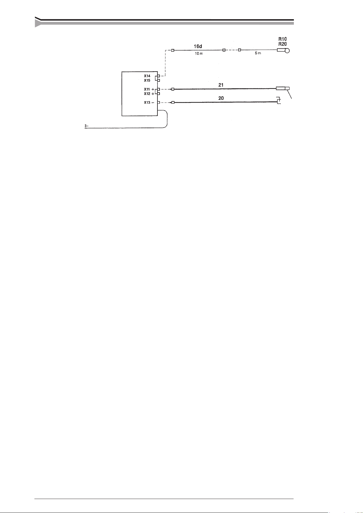
1.3.3. Cables
Pro Evolution 3200
Pro Evolution 4200
Pro Evolution 5200
Pro Evolution
3200 MVU
Pro Evolution
4200 MVU
Pro Evolution
5200 MVU
16d Extension cable for remote control
20 Earth cable
21 MMA welding cable
R10, Remote control devices, see also page 5
R20
Page 7

Kemppi pro evolution 3200, 4200, 5200, 3200 mvu, 4200 mvu, 5200 mvu / 0617 – 7© Kemppi oy
max. 15
0
60
0
2. InstallatIon
2.1. sItIng the machIne
Site the machine on a stationary, horizontal, dry base in a position that does NOT
allowdust,dirtormetalparticlestoenterthemachinescoolingairow.
- Preferably site the machine somewhat higher above the
oor level.
- Ensure that the front as well as the rear of the machine
there is at least 20 cm free distance to allow good
circulation of the cooling air through the machine.
- Protect the machine against heavy rain and in hot
circumstances against direct sunshine. Ensure the free
circulation of the cooling air.
Degree of protection of machine IP23
allows at its maximum the water spray coming
in60ºangletohitmachine’soutercovering.
2.2. mountIng the control panels pl and pX
Mountingofpanelshouldonlybecarriedoutbycompetentelectrician.
Attention!Disconnectplugofmachinefrommainssocketandwaitforapprox.2min
beforeremovingcoverplate.
- On the front face of machine there is a cover plate where the control panel is mounted.
Without a panel the machine is controlled either from remote control unit or Promig
or Protig unit.
- Mount PL or PX panel according to mounting instructions delivered with them.
2.2.1. Connection to the mains supply
Kemppi Pro Evolution power sources are delivered equipped with 5 m mains cable without plug.
If local electricity regulations of operating country are stating otherwise, the mains cable should be
replaced in conformity with the local regulations.
Connection of the mains cable, mounting and change of the plug should only be carried out by a
competent electrician.
Remove the machine’s right side plate to enable the mounting of a mains cable.
See to that the machine is positioned away from the line of
particle spray, created by grinding tools etc.
rain water
Page 8

8 – Kemppi pro evolution 3200, 4200, 5200, 3200 mvu, 4200 mvu, 5200 mvu / 0617 © Kemppi oy
05
If changing the mains cable take into consideration the following:
The cable is entered into the machine through the inlet ring on the rear panel of the machine and
fastened with a cable clamp (05). The phase conductors of the cable are coupled to connectors
L1, L2 and L3. The earth protection coloured green-yellow is coupled to connector
If you are using 5-lead cable, you must connect neutral conductor with
terminalN.
*) In cables of S type there is a protective grounding conductor coloured green-yellow.
2.2.2. Welding and earth cables
Recommended copper cables with cross-sectional area are as follows:
Kemppi Pro Evolution 3200 50 ... 70 mm
2
Kemppi Pro Evolution 4200 70 ... 90 mm
2
Kemppi Pro Evolution 5200 70 ... 90 mm
2
In enclosed table are shown typical load capacities of rubber insulated copper cables, when
ambient temperature is 25 ºC and lead temperature is 85 ºC.
CABLE DUTY CYCLE ED VOLTAGE LOSS / 10m
...........................100% .........60% ...........30%
50 mm2 ..............285 A .........370 A ......... 520 A ...........0,35 V / 100 A
70 mm2 ..............355 A .........460 A ......... 650 A ...........0,25 V / 100 A
95 mm2 ..............430 A .........560 A ......... 790 A ...........0,18 V / 100 A
Do not overload welding cables due to voltage losses and heating.
Fasten the earth clamp of the return current cable carefully, preferably direct onto the piece to be
welded. The contact surface of the earth clamp should always be as large as possible.
Clean the fastening surface from paint and rust.
3. operatIon control swItches and
potentIometers and theIr use
3.1. maIn swItch I/o
When you turn the switch into I-position, pilot lamp H11 on the front face is illuminated and the
machine is ready for use.
Always turn the machine on and off with the mains switch, never use the
mainsplugsasaswitch.
Sizes of the mains cables and fuse ratings for the machine at 100% duty cycle are specied in
the table below:
Rated voltage Mains voltage range Fuses,
slow-blow
Connection
cable *) mm
2
Pro Evolution 3200 400 V 3~ 360 V… 440 V 25 A 4 x 6.0 S
Pro Evolution 4200 400 V 3~ 360 V… 440 V 35 A 4 x 6.0 S
Pro Evolution 5200 400 V 3~ 360 V… 440 V 35 A 4 x 6.0 S
Pro Evolution 3200 MVU 400 V 3~ 230 V 3~ 360 V… 440 V 200 V… 260 V 35 A 4 x 6.0 S
Pro Evolution 4200 MVU 400 V 3~ 230 V 3~ 360 V… 440 V 200 V… 260 V 50 A 4 x10 S
Pro Evolution 5200 MVU 400 V 3~ 230 V 3~ 360 V… 440 V 200 V… 260 V 60 A 4 x 16 S
Page 9

Kemppi pro evolution 3200, 4200, 5200, 3200 mvu, 4200 mvu, 5200 mvu / 0617 – 9© Kemppi oy
0 =
9
-9
0
t
I
2
3.2. pIlot lamps
The pilot lamps of the machine report the electric operation:
The green pilot lamp H11 when lit indicates that the machine is on and ready for use and it
is connected to the mains supply with the main switch in the I-position.
H12 indicates when lit that the thermal protection of the machine has been activated due
to over heating. The cooling fan will continue to run and cool the machine down and when
the lamp is off the machine ia ready to weld.
3.3. local or remote control of weldIng current
You can control welding current either from local controls of PX or PL control panel, or from
remote control unit which is connected to remote control connector X14 or X15, or from Promig
or Protig unit.
Selector switch of control panel has to be in a position corresponding to control mode: local
control / MIG/TIG / remote control unit.
Suitable remote control units R10 and R20, see page 5.
At MIG and TIG welding, current control is made according to operation instruction of control-
ling MIG or TIG unit.
3.4. operatIon of coolIng fan
In Kemppi Pro Evolution 3200 there is one and in 4200 and 5200 there are two simultaneously
operating fans.
- The fan is started for a moment when main switch is placed into postion I.
- The fan will start during welding as the machine heats up and it will run for 1 to 10 minutes
after the welding has stopped.
- On no-load fan is started in intervals of approx. half an hour for minute’s time.
Soft arc. Object to reduce amount of spatter in welding at the upper end of recommen-
ded currents for electrode.
Factory setup (PX). Normal setting for all electrode types.
Rough arc. Object e.g. cellulose covered electrodes and thin stainless electrode in
welding at the lower end of the recommended curents for electrode.
Roughening
Factory setup
Softening
4. accessorIes
4.1. pl and pX control panels’ operatIon In
mma weldIng
4.1.1. Control for MMA welding dynamics (PL, PX)
With control for electrode dynamics you can inuence arc behaviour in different kinds of operation situations.
When arc is roughened, blowing is increasing and at the same time also spatter.
Page 10

10 – Kemppi pro evolution 3200, 4200, 5200, 3200 mvu, 4200 mvu, 5200 mvu / 0617 © Kemppi oy
9
-9
0
I
2
t
U
2
max.
I
2
4.1.2. Control of ignition pulse current (PX)
Display 0 corresponds to factory set up of ignition pulse. Number of ignition pulsesd epends on
electrode type and diameter which are used. Ignition pulse changes with set value of welding
current in such a way that at low values ignition pulse is low and short and at high values it is
higher and longer.
Low, short ignition pulse. Object e.g. small stainless electrodes.
4.1.3. Meter display (PL, PX)
Voltage meter shows machine’s terminal voltage which is voltage between connectors X11/X12
and X13.
Accurancy of current true value in respect to real value is ±2,5 %, ±2 A.
Accurancy of voltage true value in respect to real value is ±2,5 %, ±0,2 V.
Depending on welding cable legth and copper cross section, real arc voltage and meter display
might differ main volts from each other. Error will incease when current is growing. See table in
paragraph ”Welding and earth cables”, page 8.
In current measurement the same error won’t appear.
4.1.4. Operation mede selection (PX)
Normal MMA welding
In normal MMA welding there are constant current characteristics in the machine. The machine
is trying to keep welding current value regardless of arc length changes.
0 = factory set up
Factory set up. Object e.g. basic electrodes.
High, long ignition pulse. Object e.g. high efciency electrodes.
U2=20V+0,04xI2
norm line
statically constant current
Page 11

Kemppi pro evolution 3200, 4200, 5200, 3200 mvu, 4200 mvu, 5200 mvu / 0617 – 11© Kemppi oy
U2=20V+0,04xI
2
U
2
U
U
2
I
2
I
2
Point to point welding
Point to point welding is necessary then when the seam to be welded does not withstand heat of
continuous arc and welding has to be carried out by interrupting arc. The reason is usually thin
materials or variable ttings.
The machine has characteristic curve which makes interrupting of arc easier when electrode is
drawn further from seam.
6. maIntenance
The amount of use and the working environment shoud be taken into consideration when
planning the frequency of maintenance of the machine. Careful use and preventive maintenance
will help to ensure trouble-free operation.
6.1. cables
Check the condition of welding and connection cables daily. Do not use damaged cables.
Make sure that the mains cables in use are safe and according to laid down regulations.
The repair and mounting of a mains connection cables should be carried out only by an
authorized electrician.
Carbon arc gouging
In carbon arc gouging there are dynamic constant voltage curves. If the tip gouging carbon
makes a short circuit, the power source will make an strong increase to the current, the short
circuit ends rapidly and the arc will remain or reignite easier.
5. coolIng unIt supply
1~230 v / 250 va
Kemppi Pro Evolution 4200 and 5200 power sources have as stardard a by productive earthed
outlet X16 isolated safety transformer. Procool cooling unit is connected to this outlet.
U is limited below max. voltage
of machine
statically constant current
dynamically constant voltage
Page 12

12 – Kemppi pro evolution 3200, 4200, 5200, 3200 mvu, 4200 mvu, 5200 mvu / 0617 © Kemppi oy
6.2. power source
Note! Disconnect the plug of the machine from the mains socket and wait
approx.2minutes(capacitorcharge)beforeremovingthecoverplate.
Check at least every half year:
- Electric connectors of the machine - clean the oxidized parts and tighten the loosened ones.
- Note! You must know correction tension torques before starting the reparation of the joints.
- Clean the inner parts of the machine from dust and dirt e.g. with a soft brush and vacuum
cleaner. Also clean the ventilation net behind the front grate.
- Do not use compressed air, there is a risk that dirt is packed even more tightly into gaps
of cooling proles.
- Do not use pressure washing device.
- Only authorized electrician shall carry out repairs to the machines.
6.3. regular maIntenance
Kemppi Service Workshops make regular maintenance according to agreement.
The major points in the maintenace procedure are listed as follows:
- Cleaning of the machine
- Checking and maintenance of the welding tools
- Checking of connectors, switches and potentiometers
- Checking of electric connections
- Meter checking
- Checking of mains cable and plug
- Damaged parts or parts in bad connection are replaced by new ones
- Maintenace testing. Operation and performance values of the machine are checked, and
adjusted when necessary by means of test equipment.
7. operatIon dIsturbances
In case of problems contact the Kemppi works in Lahti, Finland, or your local Kemppi dealer.
Check the maintenace objects before the machine is sent to the Service Workshop.
7.1. operatIon of the overload protectIon
Yellow pilot lamp H12 of thermal protection is lit when thermostat has operated due to
overheating of machine.
7.2. control fuses
Fuse F11, 6,3 A delayed, on the rear wall of machine is as protection for connection of auxiliary
devices X14-15.
Voltage unit for auxiliary devices (1~230 V/240 VA) has a fuse of its own F12 1,0 A delayed.
Usesametypeandratingoffusewhichismarkedbesidethefuseadapter.
Damagecausedbyawrongtypefuseisnotcoveredbytheguarantee.
The thermostat of machine will operate, if machine is continuously loaded over rated values or
cooing air circulation is blocked.
Cooling fan cools down the machine and when the pilot lamp is not lit the machine is automatically ready for welding.
Page 13

Kemppi pro evolution 3200, 4200, 5200, 3200 mvu, 4200 mvu, 5200 mvu / 0617 – 13© Kemppi oy
8. orderIng numbers
Kemppi Pro Evolution 3200 6131320
Kemppi Pro Evolution 4200 6131420
Kemppi Pro Evolution 5200 6131520
Kemppi Pro Evolution 3200 MVU 613132003
Kemppi Pro Evolution 4200 MVU 613142003
Kemppi Pro Evolution 5200 MVU 613152003
Return current cable 5 m - 50 mm
2
6184511
Return current cable 5 m - 70 mm
2
6184711
Cable for MMA welding 5 m - 50 mm
2
6184501
Cable for MMA welding 5 m - 70 mm
2
6184701
PL 6185801
PX 6185802
R10 6185409
R20 6185419
Remote controlled interconnecting cable 10 m 6185481
T10 6185231
T120 6185252
P40 6185264
P40L 6185264L
P30W 6185262
7.3. under- and overvoltages In the maIns supply
Primary circuits of machine are protected against sudden, transient overvoltages.
Machine is designed to withstand 3 x 440 V voltage continiously (see technical data). See to
it that voltage is kept within admissble limits especially when mains supply is taken e.g. from
combusition engine generator.
If the mains has undervoltage (under approx. 300 V), machine control stops to operate automatically.
7.4. loss of a phase In the maIns supply
Loss of a phase causes noticeable poorer welding properties than normally or the machine
doesn’t get started at all. Loss of a phase can be due to following:
- blowing of mains supply fuse
- defective mains cable
- bad connection of mains connection cable on terminal block or plug of machine
7.5. dIsposal of the machIne
Do not dispose of electrical equipment together with normal waste!
In observance of European Directive 2002/96/EC on Waste Electrical and Electronic
Equipment and its implementation in accordance with national law, electrical equipment
that has reached the end of its life must be collected separately and returned to an
environmentally compatible recycling facility. As the owner of the equipment, you should
get information on approved collection systems from our local representative.
By applying this European Directive you will improve the environment and human
health!
Page 14

14 – Kemppi pro evolution 3200, 4200, 5200, 3200 mvu, 4200 mvu, 5200 mvu / 0617 © Kemppi oy
9. technIcal data
Pro Evolution 3200 Pro Evolution 4200 Pro Evolution 5200
Mains voltage
3~50/60 Hz 400 V -15%...+20% 400 V -15%...+20% 400 V -15%...+20%
Rated power
80 % ED 420 A / 19,7 kVA 520 A / 26,6 kVA
100 % ED 320 A / 13,3 kVA 400 A / 18,6 kVA 440 A / 20,0 kVA
Connection cable/
fuse delayed 4 x 6 S - 5 m / 25 A 4 x 6S - 5 m /35 A 4 x 6S - 5 m / 35 A
Max. welding voltage 40 0C
70 % ED 520 A / 40,0 V
80 % ED 420 A / 36,8 V
100 % ED 320 A / 32,8 V 400 A / 36 V 440 A / 37,6 V
Max. welding voltage 20 0C
100 % ED 320 A / 32,8 V 420 A / 36,8 V 480 A / 39,6 V
Welding current range
MMA 10 A ... 320 A 10 A ... 420 A 10 A ... 520 A
TIG 5 A ... 320 A 5 A ... 420 A 5 A ... 520 A
MIG 12 V ... 37 V 12 V ... 39 V 12 V ... 42 V
Max. welding voltage 46 V / 300 A 46 V / 400 A 50 V / 500 A
Open circuit voltage appr. 65 V appr. 65 V appr. 65 V
Open circuit power < 75 W < 75 W < 75 W
Efciency
at nominal values appr. 85 % appr. 85 % appr. 85 %
Power factor
at nominal values appr. 0,93 appr. 0,93 appr. 0,93
Storage temperature
range -40 ... +60 0C -40 ... +60 0C -40 ... +60 0C
Operating
temperature range -20 ... +40 0C -20 ... +40 0C -20 ... +40 0C
Temperature class H (180
0
C) / B (130 0C) H (180 0C) / B (130 0C) H (180 0C) / B (130 0C)
Degree of protection IP 23 C IP 23 C IP 23 C
Extemal dimensions
length 530 mm 530 mm 530 mm
width 230 mm 230 mm 230 mm
height 520 mm 520 mm 520 mm
Weight 37 kg 41 kg 48 kg
Voltage supply for
auxiliary devices 50 V DC 50 V DC 50 V DC
X 14, X 15 fuse 6,3 A delayed fuse 6,3 A delayed fuse 6,3 A delayed
Voltage supply for cooling unit
PROCOOL 10 1~, 230 V / 250 VA 1~, 230 V / 250 VA 1~, 230 V / 250 VA
X 16 fuse 1,0 A delayed fuse 1,0 A delayed fuse 1,0 A delayed
Page 15

Kemppi pro evolution 3200, 4200, 5200, 3200 mvu, 4200 mvu, 5200 mvu / 0617 – 15© Kemppi oy
9. technIcal data
Pro Evolution 3200 MVU Pro Evolution 4200 MVU Pro Evolution 5200 MVU
Mains voltage
3~50/60 Hz 400 V -15%...+20% 400 V -15%...+20% 400 V -15%...+20%
230 V -10%...+10% 230 V -10%...+10% 230 V -10%...+10%
Rated power
80 % ED 420 A / 19,7 kVA 520 A / 26,6 kVA
100 % ED 320 A / 13,3 kVA 400 A / 18,6 kVA 440 A / 20,0 kVA
Connection cable/
fuse delayed 4 x 6 S - 5 m / 35 A 4 x 10S - 5 m / 50 A 4 x 16S - 5 m / 63 A
Max. welding voltage 40 0C
70 % ED 520 A / 40,0 V
80 % ED 420 A / 36,8 V
100 % ED 320 A / 32,8 V 400 A / 36 V 440 A / 37,6 V
Max. welding voltage 20 0C
100 % ED 320 A / 32,8 V 420 A / 36,8 V 480 A / 39,6 V
Welding current range
MMA 10 A ... 320 A 10 A ... 420 A 10 A ... 520 A
TIG 5 A ... 320 A 5 A ... 420 A 5 A ... 520 A
MIG 12 V ... 37 V 12 V ... 39 V 12 V ... 42 V
Max. welding voltage 46 V / 300 A 46 V / 400 A 50 V / 500 A
Open circuit voltage appr. 65 V appr. 65 V appr. 65 V
Open circuit power < 75 W < 75 W < 75 W
Efciency
at nominal values appr. 85 % appr. 85 % appr. 85 %
Power factor
at nominal values appr. 0,93 appr. 0,93 appr. 0,93
Storage temperature
range -40 ... +60 0C -40 ... +60 0C -40 ... +60 0C
Operating
temperature range -20 ... +40
0
C -20 ... +40 0C -20 ... +40 0C
Temperature class H (180
0
C) / B (130 0C) H (180 0C) / B (130 0C) H (180 0C) / B (130 0C)
Degree of protection IP 23 C IP 23 C IP 23 C
Extemal dimensions
length 530 mm 530 mm 530 mm
width 230 mm 230 mm 230 mm
height 630 mm 630 mm 630 mm
Weight 45 kg 49 kg 56 kg
Voltage supply for
auxiliary devices 50 V DC 50 V DC 50 V DC
X 14, X 15 fuse 6,3 A delayed fuse 6,3 A delayed fuse 6,3 A delayed
Voltage supply for cooling unit
PROCOOL 10 1~, 230 V / 250 VA 1~, 230 V / 250 VA 1~, 230 V / 250 VA
X 16 fuse 1,0 A delayed fuse 1,0 A delayed fuse 1,0 A delayed
Page 16

16 – Kemppi pro evolution 3200, 4200, 5200, 3200 mvu, 4200 mvu, 5200 mvu / 0617 © Kemppi oy
10. terms of guarantee
Kemppi Oy provides a guarantee for products manufactured and sold by them if defects in
manufacture and materials occur. Guarantee repairs must be carried out only by an Authorised
Kemppi Service Agent. Packing, freight and insurance costs to be paid by orderer. The guarantee is
effected on the date of purchase. Verbal promises which do not comply with the terms of guarantee
are not binding on guarantor.
Limitations on guarantee
The following conditions are not covered under the terms of guarantee: defects due to natural wear
and tear, non-compliance with operating and maintenance instructions, connection to incorrect or
faulty supply voltage (including voltage surges outside equipment spec.), incorrect gas pressure,
overloading, transport or storage damage, re of damage due to natural causes i.e. lightning or
ooding.
This guarantee does not cover direct or indirect travelling costs, daily allowances or accommodation.
Note: Under the terms of guarantee, welding torches and their consumables, feeder drive rolls and
feeder guide tubes are not covered. Direct or indirect damage due to a defective product is not
covered under the guarantee. The guarantee is void if changes are made to the product without
approval of the manufacturer, or if repairs are carried out using non-approved spare parts.
The guarantee is also void if repairs are carried out by non-authorised agents.
Undertaking guarantee repairs
Guarantee defects must be informed to Kemppi or authorised Kemppi Service Agents within the
guarantee period. Before any guarantee work is undertaken, the customer must provide proof of
guarantee or proof of purchase, and serial number of the equipment in order to validate the guarantee.
The parts replaced under the terns of guarantee remain the property of Kemppi.
Following the guarantee repair, the guarantee of the machine or equipment, repaired or replaced,
will be continued to the end of the original guarantee period.
Page 17

KEMPPI OY
PL 13
FIN – 15801 LAHTI
FINLAND
Tel (03) 899 11
Telefax (03) 899 428
www.kemppi.com
KEMPPIKONEET OY
PL 13
FIN – 15801 LAHTI
FINLAND
Tel (03) 899 11
Telefax (03) 7348 398
e-mail: myynti.fi @kemppi.com
KEMPPI SVERIGE AB
Box 717
S – 194 27 UPPLANDS VÄSBY
SVERIGE
Tel (08) 590 783 00
Telefax (08) 590 823 94
e-mail: sales.se@kemppi.com
KEMPPI NORGE A/S
Postboks 2151, Postterminalen
N – 3103 TØNSBERG
NORGE
Tel 33 34 60 00
Telefax 33 34 60 10
e-mail: sales.no@kemppi.com
KEMPPI DANMARK A/S
Literbuen 11
DK – 2740 SKOVLUNDE
DANMARK
Tel 44 941 677
Telefax 44 941 536
e-mail:sales.dk@kemppi.com
KEMPPI BENELUX B.V.
Postbus 5603
NL – 4801 EA BREDA
NEDERLAND
Tel +31 (0)76-5717750
Telefax +31 (0)76-5716345
e-mail: sales.nl@kemppi.com
KEMPPI (UK) Ltd
Martti Kemppi Building
Fraser Road
Priory Business Park
BEDFORD, MK443WH
ENGLAND
Tel 0845 6444201
Fax 0845 6444202
e-mail: sales.uk@kemppi.com
KEMPPI FRANCE S.A.
65 Avenue de la Couronne des Prés
78681 EPONE CEDEX
FRANCE
Tel (01) 30 90 04 40
Telefax (01) 30 90 04 45
e-mail: sales.fr@kemppi.com
KEMPPI GmbH
Otto – Hahn – Straße 14
D – 35510 BUTZBACH
DEUTSCHLAND
Tel (06033) 88 020
Telefax (06033) 72 528
e-mail:sales.de@kemppi.com
KEMPPI SP. z o.o.
Ul. Piłsudskiego 2
05-091 ZA¸BKI
Poland
Tel +48 22 781 6162
Telefax +48 22 781 6505
e-mail: info.pl@kemppi.com
KEMPPI WELDING
MACHINES AUSTRALIA PTY LTD
P.O. Box 404 (2/58 Lancaster Street)
Ingleburn NSW 2565, Australia
Tel. +61-2-9605 9500
Telefax +61-2-9605 5999
e-mail: info.au@kemppi.com
Ver. 9
www.kemppi.com
 Loading...