

Page 1
Operation instructions english
Gebrauchsanweisung deutsch
Gebruiksaanwijzing nederlands
Manuel dutilisation français
1926280E
Procool 10
Page 2

CONTENTS
1. PREFACE ........................................................................................................................ 3
1.1. Introduction .......................................................................................................................3
1.2. Product introduction .......................................................................................................... 3
1.3. Operation safety................................................................................................................4
1.2.1. Operation control and connectors ................................................................................... 3
2. INSTALLATION ............................................................................................................... 5
2.1. Mounting of Procool 10 unit onto transport carriage ......................................................... 5
2.2. Connection to the mains supply ........................................................................................ 5
3. OPERATION.................................................................................................................... 6
3.1. Pilot lamps.........................................................................................................................6
3.2. Operation functions........................................................................................................... 6
4. OPERATION DISTURBANCES ...................................................................................... 6
4.1. Protective operations/operation disturbances ................................................................... 7
4.2. Control fuse.......................................................................................................................7
5. MAINTENANCE ..............................................................................................................8
5.1. Regular maintenance........................................................................................................ 8
6. TECHNICAL DATA AND TERMS OF GUARANTEE ...................................................... 9
6.1. Technical data ...................................................................................................................9
6.2. Terms of guarantee .........................................................................................................10
2 – Procool 10/0109
© COPYRIGHT KEMPPI OY
Page 3
1. PREFACE
1.1. INTRODUCTION
Congratulations on having purchased this product. Properly installed Kemppi products should
prove to be productive machines requiring maintenance at only regular intervals. This manual
is arranged to give you a good understanding of the equipment and its safe operation. It also
contains maintenance information and technical specications. Read this manual from front to
back before installing, operating or maintaining the equipment for the rst time. For further
information on Kemppi products please contact us or your nearest Kemppi distributor.
The specications and designs presented in this manual are subject to change without prior
notice.
In this document, for danger to life or injury the following symbol is used:
Read the warning texts carefully and follow the instructions. Please also study the Operation
safety instructions and respect them when installing, operating and servicing the machine.
1.2. PRODUCT INTRODUCTION
Cooling liquid unit Procool 10 for KEMPPI PRO is designed for cooling MIG welding guns and
TIG welding torches in demanding professional use.
Operation of Procool 10 is controlled with microprocessor.
Device assemblies being suitable for various welding methods as well as operating instruction
has been described in manual for each unit. This manual handles installation and use of Procool
cooling liquid unit.
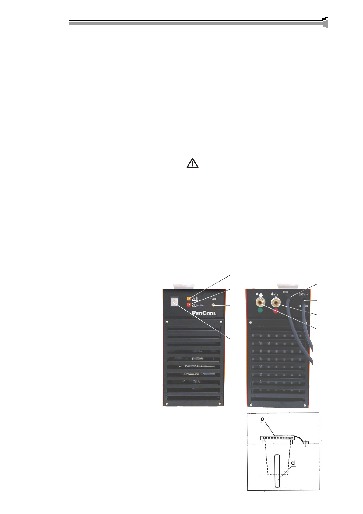
1.2.1. Operation control and connectors
H1 Warning lamp for thermal
shield
H2 Signal lamp for pressure
guard
S1 I/O main switch with
signal lamp
S2 Test/ll switch
W1 Mains connecting cable
W2 Control cable
a Cooling liquid connection
Supply R 3/8
b Cooling liquid connection
Return R 3/8
H1
W2
H2
W1
W1
b
a
S1
c Filler hole for liquid tank
d Control opening for liquid level
© COPYRIGHT KEMPPI OY
Procool 10/0109 – 3
Page 4

1.3. OPERATION SAFETY
Please study these Operation safety instructions and respect them when installing, operating and
servicing the machine.
Welding arc and spatters
Welding arc hurts unprotected eyes. Be careful also with reecting arc ash. Welding arc and
spatter burn unprotected skin. Use safety gloves and protective clothing.
Danger for re or explosion
Pay attention to re safety regulations. Remove ammable or explosive materials from welding
place. Always reserve sufcient re-ghting equipment on welding place. Be prepared for
hazards in special welding jobs, eg. for the danger of re or explosion when welding container
type work pieces. Note! Fire can break out from sparks even several hours after the welding
work has been nished!
Mains voltage
Never take welding machine inside a work piece (eg. container or truck). Do not place welding
machine on a wet surface. Always check cables before operating the machine. Change defect
cables without delay. Defect cables may cause an injury or set out a re. Connection cable must
not be compressed, it must not touch sharp edges or hot work pieces.
Welding power circuit
Isolate yourself by using proper protective clothing, do not wear wet clothing. Never work on
a wet surface or use defect cables. Do not put MIG-gun or welding cables on welding machine
or on other electric equipment. Do not press MIG-gun switch, if the gun is not directed towards
a work piece.
Welding fumes
Take care that there is sufcient ventilation during welding. Take special safety precautions
when welding metals which contain lead, cadmium, zinc, mercury or beryllium.
4 – Procool 10/0109
© COPYRIGHT KEMPPI OY
Page 5

2. INSTALLATION
2.1. MOUNTING OF PROCOOL 10 UNIT ONTO
TRANSPORT CARRIAGE
PRO 3200 Evolution
PRO 4200 Evolution
PRO 5200 Evolution
1. Place the Procool 10 unit onto transport carriage P30W 6185262 on left side of power source
in such a way that locking pins on bottom of the Procool 10 t to holes of carriage. Push the
Procool backwards so that the unit would be locked onto the carriage. Finally lock the Procool
10 from the front side to transport carriage with latch plate and screw.
Procool 10
2. Connect mains cable of the Procool 10 to earthed outlet of the PRO-power source.
3. Connect control cable of the Procool 10 to unoccupied control connector of the power source
or to the MIG or TIG unit.
Before you connect the hoses make sure that they don’t bring dirt, metal powder etc.
To cooling liquid circulation system.
4. Connect cooling liquid hoses to the MIG or TIG unit according to instructions. Note that
colour codes for hoses correspond to those colour codes which are on rear wall of the Procool
10 unit.
5. The reservoir is lled with 40 % antifreeze according to British Standard BS3151. Filling
amount is approx. 3 l. Note in addition liquid tilling of interconnecting cables of approx.
1 1/15 m.
6. Start the power source and the Procool 10. Press the switch S2 of the Procool 10 until the pilot
lamp H2 is swswitched off. Check still after that liquid level and return ow of the reservoir. Add
liquid when necessary. It is forbidden to use the switch s2 when the reservoir is empty!
Don’t swallow cooling liquid. If somebody has swallowed the liquid, send him imme-
diately to doctor. Avoid contact with skin and eyes. Wash with clean water.
2.2. CONNECTION TO THE MAINS SUPPLY
The Procool 10 unit is delivered equipped with 0,8 m mains cable with plug.
Mains cable is recommended always to be connected to the safety voltage schuko outlet of the
PRO power source.
Connection of the mains cable and mounting and change of the plug should only be carried
out by a competent electrician.
Before connecting the mains cable remove casing plate of the machine.
© COPYRIGHT KEMPPI OY
Procool 10/0109 – 5
Page 6

By mounting of the mains cable take into attention the following:
The cable is entered into the machine through the inlet ring on the rear wall of the machine and
fastened with a cable clamp (05). The phase conductor of the cable is coupled to terminal L and
the neutral conductor must be coupled to terminal N. The earth protection coloured green-yellow
is coupled to connector
Sizes of the mains cable and fuse ratings for the machine at 100 % duty cycle are specied
in the table below:
Rated voltage ...................230 V 1~
Mains voltage range ......... 220 V -10% … 240 V +6%
Fuse, slow-blow................ 10 A
Connection cable *) mm2..3 x 1,5 S
*) In cable of S type there is a protective grounding conductor coloured green-yellow.
3. OPERATION
3.1. PILOT LAMPS
Pilot lamp for readiness for use is connected to main switch S1 and is always illuminated,
when the machine is connected to mains supply and the main switch is in I-position.
Yellow pilot lamp H 1 of thermal protection is always illuminated when thermostat has
released due to overheating of cooling liquid. The cooling with fan is operating and when
the pilot lamp is switched off, the machine is again ready for welding.
Red pilot lamp of pressure guard is illuminated when the start pressure is under
the set minimum value.
3.2. OPERATION FUNCTIONS
MIG or TIG device starts the Procool 10 unit automatically for the welding time:
Welding time less than 15 s:
The liquid circulation ends after 15 s from welding start.
Welding time more than 15 s:
The liquid circulation is continued for 5 min starting from welding end.
If you weld again within above-mentioned 5 min, the liquid circulation is continued for 5 min
starting from next welding end.
4. OPERATION DISTURBANCES
In case of problems contact the Kemppiworks in Lahti, Finland, or your Kemppidealer.
Check service objects before sending the machine to service repair shop.
6 – Procool 10/0109
© COPYRIGHT KEMPPI OY
Page 7

4.1. PROTECTIVE OPERATIONS/OPERATION
DISTURBANCES
The Procool 10 unit is protected against dry operation with pressure guard (less than 1 bar)
which is on pressure side and against overheating (more than 65 °C) with sensor which is
placed into reservoir.
Disturbance situation
Pilot lamp H2 for pressure illuminates
during welding, welding and liquid circulation
are stopped
Pilot lamp H1 for temperature illuminates,
welding is stopped, but liquid circulation
is continued.
Pilot lamp H2 is ashing when there is normal
pause in liquid circulation
Return hose of current
Temperature sensor
Adjustment screw
Reason
In system low liquid pressure during welding
Locate liquid leakage or operating disturbance
with switch S2. Check liquid amount.
Liquid overheating.
Wait until pilot lamp H1 is switched off.
Pressure guard is broken or there is pressure in
system.
60 mm
surface
level
Pressure guard
NOTE! If pilot lamp for pressure illuminates, liquid circulation operates from test switch S2.
Isn’t there any leakage, check disturbance as follows:
1. Press on switch S2.
2. Check through lling opening of reservoir that liquid is returned to reservoir. If any
liquid doesn’t come, take contact with nearest KEMPPI authorised service repair shop.
3. Continue pressing on switch S2 and adjust freely adjustment screw of pressure guard
in such a way that pilot lamp H2 is only just switched off.
4. Release switch S2 and wait for approx. 10 s and check that pilot lamp H2 is not
ashing.
5. Still check by welding for approx. 20 s that there aren’t any more disturbances.
Daily check with test switch that liquid is also returned to reservoir.
4.2. CONTROL FUSE
On circuit card there is the fuse FA101 of 0,63 A, slow-blow.
A use same type and rating of fuse which is marked beside the fuse adapter
Damage caused by a wrong type fuse, is not covered by the guarantee.
© COPYRIGHT KEMPPI OY
Procool 10/0109 – 7
Page 8

5. MAINTENANCE
The amount of use and the working environment should be taken into consideration when
planning the frequency of maintenance. Careful use and preventive maintenance will help to
ensure trouble-free operation.
Daily
• Daily check amount of liquid
IfIf cooling liquid has boiled, it must be replaced, because then the solution has lost
its metal coats protective effect.
Distilled water is not recommended to be used due to alga and bacterial ora which
tends to grow in it.
• Daily check gaskets of welding ends and liquid hoses. Don’t use leleaking welding
ends or hoses!
Every six months
• Replace cooling liquid and rinse tubes and reservoir with clean water.
Check that heat sensor is fastened with the reservoir!
• Check connections of hoses and electric wires.
0ther repairs and mountings of mains connection cables should be carried out only
by an authorised electrician.
5.1. REGULAR MAINTENANCE
Kemppi service repair shops make regular maintenance according to agreement.
The major points in the maintenance procedure are listed as follows:
• Cleaning of the machine
• Checking of connectors and switches
• Checking of electric connections
• Checking of mains cable and plug
• Damaged parts or parts in bad condition are replaced by new ones
• Maintenance testing. Operation and performance values of the machine are checked,
and adjusted when necessary by means of test equipment.
8 – Procool 10/0109
© COPYRIGHT KEMPPI OY
Page 9

6. TECHNICAL DATA AND TERMS
OF GUARANTEE
6.1. TECHNICAL DATA
Mains voltage 1~, 50/60 Hz 220 V ±1% ... 240 V +6%
Rated power 100 % ED 120 W
Connection cable / fuse 3 x 1,5S - 0,8 m / 10 A slow-blow
Power factor 0,42
Control voltage 50 V DC
Cooling power 1,25 kW
Max. start pressure 400 kPa
Connection of cooling liquid hoses R3/8 ball/cone connector (DIN)
Cooling liquid 40 % glycol/water mixture British Standard BS3151
Reservoir volume approx. 3 l
Storage temperature range -40 ... +60 °C
Operation temperature range -20 ... +40 °C
Temperature class H (180 °C) / B (130 °C)
Degree of protection IP 23
External dimensions length 450 mm
width 190 mm
heigth 420 mm
Weight 16 kg
The product meets conformity requirements for CE marking.
© COPYRIGHT KEMPPI OY
Procool 10/0109 – 9
Page 10

6.2. TERMS OF GUARANTEE
KEMPPI OY provides a guarantee for products manufactured and sold by them if defects in
manufacture and materials occur.Guarantee repairs must be carried out only by an Authorized
KEMPPI Service Agent. Packing, freight and insurance costs to be paid by third party. The
guarantee is effected on the day of purchase. Verbal promises which do not comply with the
terms of guarantee are not binding on guarantor.
Limitations on guarantee
The following conditions are not covered under terms of guarantee: defects due to natural
wear and tear, non-compliance with operating and maintenance instructions, connection to
incorrect or faulty supply voltage (including voltage surges outside equipment spec.), incorrect
gas pressure, overloading, transport or storage damage, re or damage due to natural causes
i.e. ligthning or ooding.
This guarantee does not cover direct or indirect travelling costs, daily allowances or accomodation.
Note: Under the terms of the guarantee, welding torches and their consumables, feed, drive
rollers and feeder guide tubes are not covered. Direct or indirect damage due to a defective
product is not covered under the guarantee. The guarantee is void if changes are made to the
product without approval of the manufacturer, or if repairs are carried out using non-approved
spare parts.
The guarantee is also void if repairs are carried out by non-authorised agents.
Guarantee period
The guarantee is valid for one year from date of purchase, provided that the machine is used
for single-shift operation.
The guarantee period for double and treble shift operation is six months and four months
respectively.
Undertaking guarantee repairs
Guarantee defects must be informed to KEMPPI or authorised KEMPPI Service Agents within
the guarantee period. Before any guarantee work is undertaken, the customer must provide proof
of purchase and serial number of the equipment in order to validate the guarantee.
The parts replaced under the terms of guarantee remain the property of KEMPPI.
Following the guarantee repair, the guarantee of the machine or equipment, repaired or replaced,
will be continued to the end of the original guarantee period.
10 – Procool 10/0109
© COPYRIGHT KEMPPI OY
Page 11

KEMPPI OY
PL 13
FIN – 15801 LAHTI
FINLAND
Tel (03) 899 11
Telefax (03) 899 428
www.kemppi.com
KEMPPIKONEET OY
PL 13
FIN – 15801 LAHTI
FINLAND
Tel (03) 899 11
Telefax (03) 7348 398
e-mail: myynti.@kemppi.com
KEMPPI SVERIGE AB
Box 717
S – 194 27 UPPLANDS VÄSBY
SVERIGE
Tel (08) 59 078 300
Telefax (08) 59 082 394
e-mail: sales.se@kemppi.com
KEMPPI NORGE A/S
PB 2151 Postterminalen
N – 3103 TØNSBERG
NORGE
Tel 33 35 80 80
Telefax 33 35 80 90
e-mail: sales.no@kemppi.com
KEMPPI A/S
Literbuen 11
DK – 2740 SKOVLUNDE
DANMARK
Tel 44 941 677
Telefax 44 941 536
e-mail:sales.dk@kemppi.com
KEMPPI BENELUX B.V.
Postbus 5603
NL – 4801 EA BREDA
NEDERLAND
Tel (076) 5717 750
Telefax (076) 5716 345
e-mail: sales.nl@kemppi.com
KEMPPI (U.K) Ltd.
4-6 Sergeants Way
Elms Industrial Estate
BEDFORD, MK 41 OEH
ENGLAND
Tel (01234) 213 581
Telefax (01234) 215 128
e-mail: sales.uk@kemppi.com
KEMPPI FRANCE S.A.
S.A. au capital de 5 000 000 F.
65 Avenue de la Couronne des Prés
78681 EPONE CEDEX
FRANCE
Tel (01) 30 90 04 40
Telefax (01) 30 90 04 45
e-mail: sales.fr@kemppi.com
KEMPPI GmbH
Otto – Hahn – Straße 14
D – 35510 BUTZBACH
DEUTSCHLAND
Tel (06033) 88 020
Telefax (06033) 72 528
e-mail:sales.de@kemppi.com
KEMPPI OY
Oddzial w Polsce
Ul. Pilsudskiego 2
05091 ZA¸BKI
Poland
Mobile phone +48 601 35 2272
e-mail: jacek.rutkowski@kemppi.com
KEMPPI SWITZERLAND SA
Chemin de la Colice 4
CH-1023 Crisser/ Lausanne
SUISSE
Tel. +41 21 6373020
Telefax +41 21 6373025
mobile +41 79 6303794
e-mail: sales.ch@kemppi.com
Manager Felix Baumgartner
KEMPPI WELDING
MACHINES AUSTRALIA PTY LTD
P.O. Box 404 (2/58 Lancaster Street)
Ingleburn NSW 2565, Australia
Tel. +61-2-9605 9500
Telefax +61-2-9605 5999
mobile (Kent E.) +61 417784287
e-mail: info.au@kemppi.com
Manager Kent Eimbrodt
www.kemppi.com
Ver. 2
 Loading...