

Page 1
MinarcTig
180, 180MLP, 250, 250MLP
Operating manual
Brugsanvisning
Gebrauchsanweisung
Manual de instrucciones
Käyttöohje
Manuel d’utilisation
Gebruiksaanwijzing
Bruksanvisning
Instrukcja obsługi
Инструкции по эксплуатации
Bruksanvisning
操作手册
EN
DA
DE
ES
FI
FR
NL
NO
PL
RU
SV
ZH
Page 2

Page 3

OPERATING MANUAL
English
Page 4

CONTENTS
1. Preface .................................................................................... 5
1.1 General ...................................................................................... 5
1.2 Machine properties .................................................................. 5
1.3 About welding .......................................................................... 6
EN
2. Machine use
2.1 Before commissioning the machine ....................................... 7
2.2 General view of the machine ................................................... 8
2.3 Distribution network ................................................................ 8
2.4 Cable connections .................................................................... 9
2.5 Welding power selection and electrodes .............................11
2.6 Adjustments and indicators (180 and 250) ...........................12
2.6.1 Welding current regulation and remote control .....13
2.6.2 MMA welding settings ..............................................13
2.6.3 TIG welding function .................................................13
2.6.4 Additional features for MLP models .........................14
3. Setup features
4. Error codes
5. Maintenance
5.1 Daily maintenance .................................................................17
5.2 Disposal ...................................................................................17
6. Ordering numbers
7. Troubleshooting
8. Technical data
......................................................................... 7
....................................................................15
..........................................................................16
.......................................................................17
...........................................................18
...............................................................19
...................................................................20
4
4
MinarcTig 180, 180MLP, 250, 250 MLP
Page 5

1. PREFACE
1.1 General
Congratulations on choosing the MinarcTig equipment. Used correctly,
Kemppi products can signicantly increase the productivity of your welding,
and provide years of economical service.
This operating manual contains important information on the use,
maintenance and safety of your Kemppi product. The technical
specications of the equipment can be found at the end of the manual.
Please read the manual carefully before using the equipment for the rst
time. For your own safety and that of your working environment, pay
particular attention to the safety instructions in the manual.
For more information on Kemppi products, contact Kemppi Oy, consult an
authorised Kemppi dealer, or visit the Kemppi web site at www.kemppi.com.
The specications presented in this manual are subject to change without
prior notice.
Important notes
Items in the manual that require particular attention in order to minimise
damage and personal harm are indicated with the ’NOTE!’ notation. Read
these sections carefully and follow their instructions.
Disclaimer
While every eort has been made to ensure that the information contained
in this guide is accurate and complete, no liability can be accepted for any
errors or omissions. Kemppi reserves the right to change the specication of
the product described at any time without prior notice. Do not copy, record,
reproduce or transmit the contents of this guide without prior permission
from Kemppi.
EN
1.2 Machine properties
MinarcTig machines are compact and robust direct current welding
machines suitable for MMA and TIG welding. Extremely light in weight for
their output power, the machines are easy to carry to the work place with
either the inbuilt moulded carry handle or the shoulder strap provided.
The 180 and 180 MLP models can be used in regular lighting circuits, i.e.,
in single-phase electric networks. The 250 and 250 MLP models require a
three-phase network.
5
5© Kemppi Oy / 1339
Page 6

EN
1.3 About welding
MinarcTig is a precise welding tool and will provide high quality results
time after time provided the correct operational procedures are followed.
Welding quality is not only inuenced by the machine itself. Personal
expertise, ancillary equipment and consumables also play an essential role,
as does the correct, fused supply power.
Welding is carried out when an electric arc is established between the
welding electrode and work piece. Welding is not possible unless the
equipment is correctly set-up, including the earthing cable attached to the
work piece. This cable creates the welding circuit that allows the welding
current to ow. Please check the earthing clamp is on the work piece to be
welded, and that the area of the clamps contact is clean and free from paint.
MMA welding
The MMA is a simple welding process. A coated MMA electrode is short
circuited to the work piece and the resulting electric arc creates a molten
pool into which the electrode wire melts. The coating around the electrode
burns to create a protective gaseous atmosphere and slag, which directly
protects the molten weld pool from atmospheric contamination. The slag
oats on the molten weld pool and solidies on the surface of the resulting
weld bead, protecting the cooling weld.
The electrode is moved slowly along the weld seam. The travel speed
is directly proportional to the size of the electrode and welding current
selected. The slag is nally removed with a chipping hammer to reveal the
weld (always use eye protection).
TIG welding
In TIG welding, the welding arc is formed between a non-consumable
tungsten electrode and the work piece. The resulting high temperature
arc melts the work piece to form a molten pool, into which ller wire of a
similar alloy composition is slowly melted. The molten weld pool and ller
wire are protected from the harmful eects of atmospheric contamination
by an inert shielding gas that ows out from the TIG welding torch’s ceramic
nozzle at a rate of approximately 8–15 litres per minute. (Gas regulator, ow
meter and pure argon shielding gas are not provided in this package.)
6
6 MinarcTig 180, 180MLP, 250, 250 MLP
Page 7

2. MACHINE USE
2.1 Before commissioning the machine
MinarcTig is packed in purpose made, recyclable packaging. However,
always ensure that the equipment has not been damaged in transportation.
Even so, make sure that all in-transport damage is reported to the machine
supplier. Do not unpack the machine under these circumstances. In addition,
before commissioning, check that you have received all of the items you
ordered along with their operating instructions.
Transportation
The machine should be transported in an upright position.
Environment
The machine is suitable for both indoor and outdoor use. In outdoor use,
protect it from heavy rain and sunshine. Store the machine in a dry and
clean environment and protect it from sand and dust during use and
storage. The recommended operating temperature range is –20 to +40
degrees centigrade.
Site the machine so that it does not come into contact with hot surfaces,
sparks and welding spatter. Make sure the airow to and from the machine
is unrestricted.
EN
7
7© Kemppi Oy / 1339
Page 8
EN
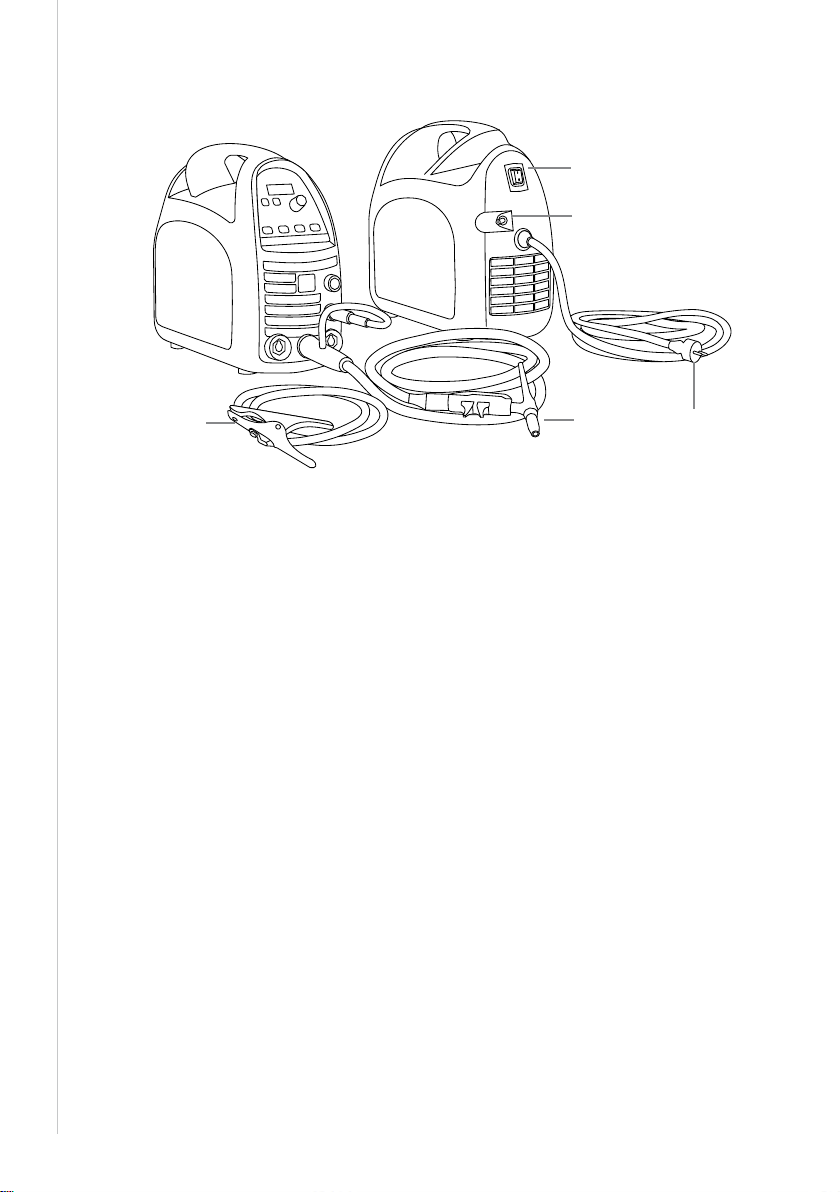
2.2 General view of the machine
3.
5.
1. Welding torch
2. Earthing cable and earthing clamp
3. Main switch
4. Mains cable (MinarcTig 180 in the picture)
5. Shielding gas hose connector
2.3 Distribution network
All regular electrical devices without special circuits generate harmonic
currents into distribution network. High rates of harmonic current may cause
losses and disturbance to some equipment.
MinarcTig 180, 180MLP:
WARNING: This equipment does not comply with IEC 61000-3-12. If it is
connected to a public low voltage system, it is the responsibility of the
installer or user of the equipment to ensure, by consultation with the
distribution network operator if necessary, that the equipment may be
connected.
MinarcTig 250, 250MLP:
This equipment complies with IEC 61000-3-12 provided that the short-circuit
power Ssc is greater than or equal to 1.5 MVA at the interface point between
the user's supply and the public supply network. It is the responsibility of
the installer or user of the equipment to ensure, by consultation with the
distribution network operator if necessary, that the equipment is connected
only to a supply with a short-circuit power Ssc greater than or equal to
1.5 MVA.
1.2.
4.
8
8 MinarcTig 180, 180MLP, 250, 250 MLP
Page 9

2.4 Cable connections
Connection to mains
The machine is equipped with a 3.3 m supply voltage cable and plug. Plug
the mains cable to a single-phase electric network.
The MinarcTig 250 is supplied with a 5 m mains cable without a plug.
Check the fuse size in Technical specications. The plug may
NOTE!
be installed only by electrical contractors and installers specialised in
performing such operations.
If you use an extension power supply cord, its cross sectional area should
be at least as large as the supply voltage cable tted to the machine. The
maximum length for the extension cable is 50 m.
The minimum power of a single-phase machine generator must be 3.5 kVA.
The recommended power is 7.0 kVA for using the machine at maximum
power.
Restrictions on generator type and power may apply in generator use. Faultfree operation of a three-phase machine also requires a suciently highpower generator. The power recommendation is more than 15 kVA.
Earthing cable
Connect the earthing cable to the negative pole in MMA welding, and to the
positive pole in TIG welding.
Before you start welding, clean the work piece surface and x the earth
return clamp to the work piece in order to create a closed and interference
free welding circuit.
EN
Welding torch (TIG)
The welding torch is used to supply shielding gas and electrical arc energy
to the weld piece. When you press the welding torch switch, the shielding
gas begins to ow and the arc is established. The TIG torch is connected to
the negative pole.
9
9© Kemppi Oy / 1339
Page 10

EN
Shielding gas
In TIG welding, shielding gas is used to prevent atmospheric contamination
of the molten weld pool and cooling weld. Normally, the shielding gas
is argon (Ar). Normally the gas ow rate is approximately 8–15 litres per
minute, but this can vary according to the welding current used and the size
of gas nozzle.
The machine is delivered with a 4.5 m shielding gas hose. Connect the gas
hose snap connector to the male connector on the machine. The other end
of the gas supply hose should be connected to the outlet of the regulator.
NOTE! Under no circumstances should you connect the hose directly to
the cylinder valve. Always use a regulator and ow meter for safe and
accurate operation.
1. Connect the hose to the reduced pressure side of the cylinder
regulator, or ow meter and tighten the connector.
2. Adjust the shielding gas ow rate with the ow regulation adjustment
screw. A suitable gas ow rate is 8–15 l/min
3. Close the cylinder valve after use.
10
10 MinarcTig 180, 180MLP, 250, 250 MLP
Page 11

2.5 Welding power selection and electrodes
TIG welding electrodes and gas nozzles
In DC TIG welding we recommend the use of the WC20 (grey) type electrode,
however other types are available.
The welding electrode size (diameter) is selected depending on the welding
current/power to be used. An electrode with an insucient diameter
compared to the welding current will melt, while excessive electrode size
will make it more dicult to ignite the arc.
Generally speaking, a 1.6 mm tungsten electrode will cover currents up to
150 A, and 2.4 mm tungsten electrode up to 250 A DC current.
Before use, grind the tungsten electrode to a sharp point at approximately
1.5 times the diameter of the electrode. If the electrode touches the work
piece during welding, re-sharpen the electrode.
MMA welding electrodes
In MMA welding, the welding electrodes must be connected to the correct
pole. Normally, the electrode holder is connected to the positive and the
earthing cable to the negative connector.
It is also important to properly adjust the welding current so that the ller
material and coating will melt properly and the welding is ecient. The table
below presents the electrode sizes available with the MinarcTig welding
machine and the corresponding welding current values.
MMA Electrodes and corresponding current settings range
EN
Electrode
diameter
Fe-Rutile
Fe-Basic
1.6 mm 2.0 mm 2.5 mm 3.25 mm 4.0 mm 5.0 mm
30-60 A 40-80 A 50-110 A 80-150 A 120–210 170–220
30-55 A 50-80 A 80-110 A 110-150 A 140–200 200–220
11
11© Kemppi Oy / 1339
Page 12

EN
2.6 Adjustments and indicators (180 and 250)
1.
2.
3.
4.
5. 6. 7.
1. Standby indicator.
2. Pre/Post gas, upslope/downslope and main current parameter
indicator.
3. Welding parameter selector arrow keys.
4. Welding process selection button (MMA or TIG).
5. 2T or 4T TIG torch switch selection button. Select 2T for short welds or
4T for long welds.
6. Ignition method selection button.
7. Current adjustment selector: panel control, TIG Torch remote or foot
pedal remote.
8. Welding current and parameter value control knob.
9. Welding current and parameter value display: time and amperes.
10. Overheating indicator.
10.
9.
8.
Switching the machine on
When you power on the machine, the green standby indicator and the main
switch are lit.
If the machine overheats or the supply voltage is too high or too low, the
welding operation automatically switches o, and the yellow overheating
indicator is illuminated. The light switches o again, when the machine
is ready for operation. Make sure that there is enough space around the
machine to allow the air to freely circulate and ow into and out o the
machine.
12
12 MinarcTig 180, 180MLP, 250, 250 MLP
Page 13

2.6.1 Welding current regulation and remote control
The welding current can be adjusted steplessly with the control knob, if
panel adjustment (PANEL) is selected.
If you want to adjust the welding current with the remote control, connect
the remote control to the machine and then select remote control with the
current adjustment selector (7). The following remote control options are
available: RTC10, RTC20, R10 and R11F. The remote foot pedal R11F can only
be used with TIG welding in 2T operation mode.
2.6.2 MMA welding settings
MMA welding is selected when the indicator next to the MMA symbol is lit.
If needed, press the process selection button to select the MMA process (4).
The machine automatically sets suitable values to the ignition time, ignition
pulse and arc dynamics.
2.6.3 TIG welding function
Select the TIG welding process by pressing the MMA/TIG button.
Torch switch control in 2T mode and HF arc ignition
The shielding gas starts to ow when the torch switch is pressed and the
welding arc is established automatically via HF ignition. The current starts to
rise (if an upslope time is established) to the set welding current level. When
you release the switch, the current starts to decrease. After the specied
downslope time, the arc is disconnected and the set post-gas time begins.
Torch switch control in 4T mode and HF arc ignition
The shielding gas starts to ow when the torch switch is pressed. When the
switch is released, the arc is automatically established via HF ignition. The
current starts to rise (if an upslope time is established) to the set welding
current level. When ready to end the welding cycle, press and release the
torch switch again. The welding current starts to drop (if a downslope time is
established) until the arc is extinguished and the set post-gas time begins.
EN
HF or Contact ignition
The TIG arc can be established with or without an HF pulse.
If the HF indicator is not lit, the arc can be established by lightly contacting
the tungsten electrode to the work piece. Press the torch trigger and then
quickly lift the contact of the tungsten electrode from the work piece (2T
function); the arc is established simultaneously and eectively.
For HF ignition, press the HF button so that the indicator is on (item 6). Press
the TIG torch trigger and hold or release, depending on whether 2T or 4T is
selected. The shielding gas ows and the HF (High Frequency arc) ignites the
welding arc.
13
13© Kemppi Oy / 1339
Page 14

EN
Setting parameters
Select the welding parameters with the arrow keys (3) and adjust the
parameter values with the control knob (8). When setting the parameters,
the display (2) will show the parameter being adjusted as well as the
numeric value that will be set for it. After three seconds, the display returns
to normal state and shows the welding current value.
2.6.4 Additional features for MLP models
8.
5.
Minilog
With the Minilog feature, you can switch between two current levels by
pressing the switch briey. The levels are the welding current and the
Minilog current.
To use the Minilog feature, press the button (5) so that the MINILOG
indicator is lit. Use the arrow buttons to move the selector to Minilog current
and then set the desired Minilog current level with the control knob (8).
The shielding gas starts to ow when the torch switch is pressed. When you
release the switch, the current starts to rise (if an upslope time is established)
to the set welding current level.
Press the torch swich shortly (<1 sec) you can then easily switch up and
down between the two levels: welding current and Minilog current.
When you press the switch for 1 second and then release it, the current
starts to decrease. After a predetermined downslope time, the arc is
disconnected.
14
14 MinarcTig 180, 180MLP, 250, 250 MLP
Page 15

Pulse welding
To use the pulse welding feature, press the PULSE button so that the ON
indicator is lit. Specify the desired welding current average (A) and pulse
time (s). The machine will set the remaining pulse values automatically.
For small welding current values, the chronological pulse ratio is 35% and
the pause current’s share of the pulse current is 35 %. The percentages are
slightly altered if the welding current average rises above 145 A.
3. SETUP FEATURES
Conguring additional features
The machine has additional features that can be selected and adjusted with
the SETUP feature. To activate and deactivate it, press both arrow buttons (3)
simultaneously for at least 5 seconds.
In the SETUP mode, the display will show the name of the parameter to be
adjusted and its numerical value. Select the parameter to be adjusted with
the arrow buttons and change the parameter value with the control knob.
The following parameters and values are available:
Name
displayed
A 1/0 0 End current level selection, 1=I min / 0 =15%
b 1/0 1 Open-circuit voltage selection,
C 1/0 0 Forced stop during downslope
d 1/0 1 Alternative switch logic of the MLP panel,
E 5% … 40% 20% Start current level selection
F 1/0 0 Restore factory settings *),
h 0.0…2.0 s 0 Minimum setting for pre-gas time
J 0,0…10,0 s 1.0 s Minumum setting for post-gas time
L 5.0…20.0 s 10.0 s Maximum setting for pre-gas time
o 15…99 s 30 s Maximum setting for post-gas time
S -3…5 0 Arc dynamics (Arc Force)
Parameter
values
Factory
setting
Description
1 = 30 V (VRD) / 0 = 95 V
with a brief pressing of the switch,
1 = On / 0 = O
1 = Minilog / 0 = 4T-LOG
(% of the welding current)
1 = Restore / 0 = No restore
EN
15
15© Kemppi Oy / 1339
Page 16

EN
t -9…0 0 Electrode ignition pulse
(-9 = No pulse / 0 = Max pulse)
U 1/0 0 Disable automatic remote control recognition.
0 = Enable automatic recognition, 1 = Disable
automatic recognition.
*) Happens when exiting SETUP mode and value is 1.
4. ERROR CODES
The machine always checks its operation automatically during start-up and
reports any failures detected. If failures are detected during start-up, they
are shown as error codes on the control panel display.
E 2: Power source undervoltage
The device has stopped because it has detected a mains undervoltage that
disturbs welding. Check the quality of the supply network.
E 3: Power source overvoltage
The machine has stopped the welding because it has detected momentary
voltage spikes or continuous overvoltage dangerous to the machine in the
electric network. Check the quality of the supply network.
E 4: Power source overheating
The power source has overheated. The cause may be one of the following:
• The power source has been used for a long time at maximum power.
• The circulation of cooling air to the power source is blocked.
• The cooling system has experienced a failure.
Remove any obstacle to air circulation, and wait until the power source fan
has cooled down the machine.
Other error codes:
The machine can show codes not listed here. In the event of an unlisted
code appearing, contact an authorised Kemppi service agent and report the
error code shown.
16
16 MinarcTig 180, 180MLP, 250, 250 MLP
Page 17

5. MAINTENANCE
All electromechanical devices require routine service maintenance
depending on usage. This type of routine maintenance will prevent hazards
and malfunctions.
We recommend that you schedule a service inspection of your welding
machine every six months. An authorised Kemppi service agent will inspect
and clean your machine, ensuring that all power connections are tight and
secure. Power connections can become loose and oxidised with frequent
and high changes in temperature.
Disconnect the machine from the mains power supply before
NOTE!
handling electric cables.
5.1 Daily maintenance
• Check the welding torch electrode. Sharpen the electrode or replace a
damaged one.
• Check the tightness of the earthing cable connections.
• Check the condition of mains and welding cables and replace
damaged cables.
5.2 Disposal
Do not dispose of electrical equipment with normal waste!
In observance of European Directive 2002/96/EC on waste electrical
and electronic equipment, and its implementation in accordance with
national law, electrical equipment that has reached the end of its life must
be collected separately and taken to an appropriate environmentally
responsible recycling facility.
The owner of the equipment is obliged to deliver a decommissioned unit
to a regional collection centre, per the instructions of local authorities
or a Kemppi representative. By applying this European Directive you will
improve the environment and human health.
EN
17
17© Kemppi Oy / 1339
Page 18

EN
6. ORDERING NUMBERS
Product Part number
Power Sources
MinarcTig 180, TTC 160 4 m MINARC180TTC4
MinarcTig 180, TTC 160 8 m MINARC180TTC8
MinarcTig 180 MLP, TTC 160 4 m MINARC180MLPTTC4
MinarcTig 180 MLP, TTC 160 8 m MINARC180MLPTTC8
MinarcTig 250, TTC 160 4 m MINARC250TTC164
MinarcTig 250, TTC 160 8 m MINARC250TTC168
MinarcTig 250, TTC 220 4 m MINARC250TTC224
MinarcTig 250, TTC 220 8 m MINARC250TTC228
MinarcTig 250 MLP, TTC 160 4 m MINARC250MLPTTC164
MinarcTig 250 MLP, TTC 160 8 m MINARC250MLPTTC168
MinarcTig 250 MLP, TTC 220 4 m MINARC250MLPTTC224
MinarcTig 250 MLP, TTC 220 8 m MINARC250MLPTTC228
Cables
Welding cable, 16 mm² 5 m 6184103
Welding cable, 25 mm² 5 m 6184201
Welding cable, 25 mm² 10 m 6184202
Earthing cable, 16 mm² 5 m 6184113
Earthing cable, 25 mm² 5 m 6184211
Earthing cable, 25 mm² 10 m 6184212
Torches
TTC 160, 4 m 627016004
TTC 160, 8 m 627016008
TTC 220, 4 m 627022004
TTC 220, 8 m 627022008
Ancillary devices
TIG welding torch controls
RTC 10 6185477
RTC 20 6185478
Gas ow gauge AR/clock 6265136
18
18 MinarcTig 180, 180MLP, 250, 250 MLP
Page 19

Shielding gas hose (4.5 m) W001077
Carrying straps 9592162
Remote control units
R 10 6185409
R11F 6185407
Mains cable (MinarcTig 250) W002982
7. TROUBLESHOOTING
Problem Cause
The main switch indicator will
not light up
Poor welding result Several factors aect the welding quality.
Overheating indicator lit The device has overheated.
No electricity connected to the machine
• Check the mains supply fuses.
• Check the mains cable and plug.
• Check that the earthing clamp is properly attached, the
point of attachment is clean and that the cable and its
connectors are intact.
• Check that the shielding gas ows out of the torch tip.
• The electric network voltage is irregular, too low or too
high.
• Ensure that cooling air has unrestricted ow.
• The machine’s duty cycle has been exceeded. Wait for
indicator to turn o.
• Too low or high supply voltage.
EN
If the machine’s malfunction is not eliminated with these measures, contact
KEMPPI service.
19
19© Kemppi Oy / 1339
Page 20

EN
8. TECHNICAL DATA
MinarcTig 180, 180 MLP
Connection voltage
Rated power at max. current
Supply current, I
Supply current, I
Connection cable
Fuse (delayed)
Duty cycle 40 °C
Welding range
Open circuit voltage
Idle power
Power factor at max. current
Efficiency at max. current
Striking voltage
Stick electrodes
External dimensions (L × W × H)
Weight
Temperature class
Degree of protection
1max
1eff
1 ~, 50/60 Hz 230 V ±15 %
TIG 6.7 kVA (180 A/17.2 V)
MMA 7.0 kVA (140 A/25.6 V)
TIG 29 A (180 A/17.2 V)
MMA 31 A (140 A/25.6 V)
TIG 18 A (120 A/14.8 V)
MMA 22 A (100 A/24.0 V)
H07RN-F 3G2.5(3x2.5 mm²) - 3 m Euro
Schuko
16 A
TIG 35 % ED 180 A/17.2 V
100 % ED 120 A/14.8 V
MMA 35 % ED 140 A/25.6 V
100 % ED 100 A/24 V
TIG 5 A/10.2 V–180 A/17.2 V
MMA 10 A/20.4 V-140 A/25.6 V
95 V (VRD 30 V)
TIG –
MMA 25 W
TIG 0.62
MMA 0.63
TIG 0.75
MMA 0.81
10 kV
MMA Ø 1.5-3.25 mm
400 × 180 × 340
7.8 kg (8.4 kg with connection
cable)
H (B)
IP23S
20
20 MinarcTig 180, 180MLP, 250, 250 MLP
Page 21

EMC class
Operating temperature range
Storage temperature range
Recommended generator
MinarcTig 250, MinarcTig 250 MLP
Connection voltage
Rated power at max. current
Supply current, I
Supply current, I
1max
1eff
Connection cable
Fuse (delayed)
Duty cycle 40 °C
Welding range
Open circuit voltage
Idle power
Power ratio at max. current
Efficiency at max. current
Striking voltage
MMA welding electrodes
External dimensions (L × W × H)
Weight
A
-20 °C...+40 °C
-40 °C...+60 °C
> 7 kVA
3 ~, 50/60 Hz 400 V –20 %... +15 %
TIG 7.2 kVA (250 A/20.1 V)
MMA 8.2 kVA (220 A/28.8 V)
TIG 10 A (250 A/20.1 V)
MMA 12 A (220 A/28.8 V)
TIG 6 A (160 A/16.4 V)
MMA 8 A (150 A/26.0 V)
H07RN-F 4G1.5(4x1.5 mm²) - 5 m
10 A
TIG 30 % ED 250 A/20.1 V
100 % ED 160 A/16.4 V
MMA 35 % ED 220 A/28.8 V
100 % ED 150 A/26.0 V
TIG 5 A/10.2 V-250 A/20.1 V
MMA 10 A/20.4 V-220 A/28.8 V
MMA 95 V (VRD 30 V)
MMA 40 W
TIG 0,92
MMA 0,91
TIG 0,80
MMA 0,86
TIG 10 kV
MMA Ø 1.5-5.0 mm
400 × 180 × 340
10.7 kg (11.6 kg with connection
cable)
EN
21
21© Kemppi Oy / 1339
Page 22

Temperature class
Degree of protection
EMC class
Minimun short circuit power Ssc of
supply network*
Operating temperature range
Storage temperature range
Recommended generator
F
IP23S
A
1.5 MVA
-20 °C...+40 °C
-40 °C...+60 °C
> 15 kVA
EN
* See paragraph 2.3.
22
22 MinarcTig 180, 180MLP, 250, 250 MLP
Page 23

Page 24

KEMPPI OY
Kempinkatu 1
PL 13
FI-15801 LAHTI
FINLAND
Tel +358 3 899 11
Telefax +358 3 899 428
export@kemppi.com
www.kemppi.com
Kotimaan myynti:
Tel +358 3 899 11
Telefax +358 3 734 8398
myynti.@kemppi.com
KEMPPI SVERIGE AB
Box 717
S-194 27 UPPLANDS VÄSBY
SVERIGE
Tel +46 8 590 783 00
Telefax +46 8 590 823 94
sales.se@kemppi.com
KEMPPI NORGE A/S
Postboks 2151, Postterminalen
N-3103 TØNSBERG
NORGE
Tel +47 33 346000
Telefax +47 33 346010
sales.no@kemppi.com
KEMPPI DANMARK A/S
Literbuen 11
DK-2740 SKOVLUNDE
DANMARK
Tel +45 4494 1677
Telefax +45 4494 1536
sales.dk@kemppi.com
KEMPPI BENELUX B.V.
Postbus 5603
NL-4801 EA BREDA
NEDERLAND
Tel +31 765717750
Telefax +31 765716345
sales.nl@kemppi.com
KEMPPI (UK) LTD
Martti Kemppi Building
Fraser Road
Priory Business Park
BEDFORD, MK44 3WH
UNITED KINGDOM
www.kemppi.com
Tel +44 (0)845 6444201
Telefax +44 (0)845 6444202
sales.uk@kemppi.com
KEMPPI FRANCE S.A.S.
65 Avenue de la Couronne des Prés
78681 EPONE CEDEX
FRANCE
Tel +33 1 30 90 04 40
Telefax +33 1 30 90 04 45
sales.fr@kemppi.com
KEMPPI GMBH
Perchstetten 10
D-35428 Langgöns
DEUTSCHLAND
Tel +49 6 403 7792 0
Telefax +49 6 403 779 79 74
sales.de@kemppi.com
KEMPPI SPÓŁKA Z O.O.
Ul. Borzymowska 32
03-565 WARSZAWA
POLAND
Tel +48 22 7816162
Telefax +48 22 7816505
info.pl@kemppi.com
KEMPPI AUSTRALIA PTY LTD
13 Cullen Place
P.O. Box 5256, Greystanes NSW 2145
SMITHFIELD NSW 2164
AUSTRALIA
Tel. +61 2 9605 9500
Telefax +61 2 9605 5999
info.au@kemppi.com
OOO KEMPPI
Polkovaya str. 1, Building 6
127018 MOSCOW
RUSSIA
Tel +7 495 739 4304
Telefax +7 495 739 4305
info.ru@kemppi.com
ООО КЕМППИ
ул. Полковая 1, строение 6
127018 Москва
Tel +7 495 739 4304
Telefax +7 495 739 4305
info.ru@kemppi.com
KEMPPI, TRADING (BEIJING) COMPANY
LTD
Room 420, 3 Zone, Building B,
No.12 Hongda North Street,
Beijing Economic Development Zone,
100176 BEIJING
CHINA
Tel +86-10-6787 6064
+86-10-6787 1282
Telefax +86-10-6787 5259
sales.cn@kemppi.com
肯倍贸易(北京)有限公司
中国北京经济技术开发区宏达
北路12号
创新大厦B座三区420室 (100176)
电话: +86-10-6787 6064
+86-10-6787 1282
传真: +86-10-6787 5259
sales.cn@kemppi.com
KEMPPI INDIA PVT LTD
LAKSHMI TOWERS
New No. 2/770,
First Main Road,
Kazura Garden,
Neelankarai,
CHENNAI - 600 041
TAMIL NADU
Tel +91-44-4567 1200
Telefax +91-44-4567 1234
sales.india@kemppi.com
KEMPPI WELDING SOLUTIONS SDN BHD
No 12A, Jalan TP5A,
Taman Perindustrian UEP,
47600 Subang Jaya,
SELANGOR, MALAYSIA
Tel +60 3 80207035
Telefax +60 3 80207835
sales.malaysia@kemppi.com
1910190
1339
 Loading...