

Page 1
MinarcMig
Evo 170, 200
Operating manual
Käyttöohje
Bruksanvisning
Bruksanvisning
Brugsanvisning
Gebrauchsanweisung
Gebruiksaanwijzing
Manuel d’utilisation
Manual de instrucciones
Instrukcja obsługi
Инструкции по эксплуатации
EN
FI
SV
NO
DA
DE
NL
FR
ES
PL
RU
Manual de utilização
Manuale d’uso
操作手册
PT
IT
ZH
Page 2

Page 3

OPERATING MANUAL
English
© Kemppi Oy / 1340
Page 4

EN
CONTENTS
1. Preface ................................................................................................................. 3
1.1 General ....................................................................................................................................... 3
1.2 Product introduction ............................................................................................................ 3
1.2.1 Properties ......................................................................................................................... 3
1.2.2 About welding ................................................................................................................. 4
2. Before you start using the unit ................................................................... 4
2.1 Unpacking ................................................................................................................................. 4
2.2 Positioning and location of the machine ...................................................................... 5
2.3 Distribution network ............................................................................................................. 5
2.4 Serial number ........................................................................................................................... 5
2.5 General view of the machine ............................................................................................. 5
2.6 Cable connections ................................................................................................................. 6
2.7 Filler wire .................................................................................................................................... 8
2.7.1 Changing the feed roll groove ........................................................................................ 8
2.7.2 Loading and threading the ller wire ............................................................................. 9
2.7.3 Reversing polarity ..........................................................................................................10
2.8 Controls and indicator lights ............................................................................................11
2.8.1 Display in automatic mode ...........................................................................................13
2.8.2 Welding power adjustment in automatic mode .........................................................13
2.8.3 Arc length trimmer in automatic mode .......................................................................14
2.8.4 Display in manual mode ...............................................................................................14
2.8.5 Adjustments in manual mode ......................................................................................15
2.9 MIG/MAG welding ................................................................................................................15
2.10 Using the shoulder strap ...................................................................................................17
3. Maintenance ....................................................................................................17
3.1 Daily maintenance ...............................................................................................................17
3.2 Maintenance of the wire feed mechanism .................................................................18
3.3 Troubleshooting ...................................................................................................................19
3.4 Storage .....................................................................................................................................19
3.5 Disposal of the machine ....................................................................................................19
4. Ordering numbers .........................................................................................20
5. Technical data ................................................................................................. 21
2
MinarcMig Evo 170, Evo 200
Page 5

1. PREFACE
1.1 General
Congratulations on choosing MinarcMig Evo welding equipment. Used correctly, Kemppi
p°roducts can signicantly increase the productivity of your welding, and provide years of
economical service.
This operating manual contains important information on the use, maintenance and safety of
your Kemppi product. The technical specications of the equipment can be found at the end
of the manual.
Please read the manual carefully before using the equipment for the rst time. For your
own safety and that of your working environment, pay particular attention to the safety
instructions in the manual.
For more information on Kemppi products, contact Kemppi Oy, consult an authorised Kemppi
dealer, or visit the Kemppi web site at www.kemppi.com.
For Kemppi’s standard safety instructions and warranty terms and conditions, please visit our
web site at www.kemppi.com.
The specications presented in this manual are subject to change without prior notice.
NOTE! Items in the manual that require particular attention in order to minimise damage and
personal harm are indicated with this symbol. Read these sections carefully and follow their
instructions.
Disclaimer
While every eort has been made to ensure that the information contained in this guide
is accurate and complete, no liability can be accepted for any errors or omissions. Kemppi
reserves the right to change the specication of the product described at any time without
prior notice. Do not copy, record, reproduce or transmit the contents of this guide without
prior permission from Kemppi.
EN
1.2 Product introduction
MinarcMig Evo 170 and 200 are easy-to-use MIG/MAG welding machines suitable for
professional industry, site and repair welding. Before use or doing any maintenance work on
the machine, read the operating manual and keep it for further reference.
MinarcMig Evo tolerates input voltage uctuation and is suitable for work on sites using
power generators and use with long power cables. The power source utilises PFC technology,
ensuring optimum usage on single phase power supplies. The IGBT inverter design delivers
reliable arc ignition and welding performance, with all ller wire types.
Welding and earth return cables are supplied in the delivery package, including gun, earth
clamp and connections.
1.2.1 Properties
The welding machine is small, ecient and light. It is easy to carry with the handle or shoulder
strap. It is suitable for a wide range of welding applications, and the possibility to use long
power extension cables makes it easy to use in worksite conditions. It is also suitable for use
with power generators.
The MinarcMig Evo 170 is set manually, with separate control for wire feed speed and voltage.
MinarcMig Evo 200 machine has both an automatic and manual operation mode. In the
automatic mode, you must rst select the ller wire material after which the welding voltage
and wire feed speed can be adjusted with one control knob, according to the thickness of
the sheet to be welded. Thus, selecting the right parameters is easy. In automatic mode, the
length of the arc, or welding heat, is trimmed with another control. In manual mode, the
welding voltage and wire feed speed are adjusted separately with their own controls. The
use of the machine is aided with an LCD display which indicates the welding current, welding
voltage and wire feed speed.
© Kemppi Oy / 1340
3
Page 6

EN
You can use steel (solid or cored wire), stainless steel, aluminium and CuSi as ller wire in the
machine. The steel wire can be 0.6 mm, 0.8 mm, 0.9 mm or 1.0 mm thick, but the machine’s
welding properties are optimum with a steel wire of 0.8 mm diameter. The stainless steel wire
can be 0.8 mm, 0.9 mm or 1.0 mm in diameter, the aluminium wire 1.0 mm and CuSi wire 0.8,
0.9 and 1.0 mm.
1.2.2 About welding
In addition to the welding machine, welding outcome is inuenced by the work piece to be
welded, welding technique and the welding environment. Therefore, recommendations in this
manual must be followed.
During welding, an electric welding circuit is created between the positive and negative
poles of the machine. On delivery, the welding gun is connected to the positive pole of the
machine terminals. The terminals are located inside the case door and should not be changed
unless you intend to run a ller wire that is directed to be used in reverse polarity, electrode
negative. When a ller wire is loaded to the machine, the wire feed mechanism drives the ller
wire through the contact tip mounted in the welding gun, and thus transfers electrical power
from the contact tip to the ller wire. The earth return clamp and cable (already connected to
the machine on delivery to the negative terminal) connects to the workpiece to be welded.
When the ller wire touches the work piece a short circuit occurs, forming the needed closed
electrical circuit, an arc is formed and welding commences. Unrestricted current ow is
possible only when the earth return clamp is properly attached to the workpiece and the
xing point of the clamp to the workpiece is clean, and free from paint and rust.
Shielding gas must be used during welding in order to prevent air from mixing with the weld
pool. Pure carbon dioxide or a mixture of argon and carbon dioxide is a suitable shielding
gas for steel ller wire. Argon + 2 % CO₂ mixture is suitable for stainless steel wires. Argon is
suitable for welding aluminium and CuSi wires. Some ller wires (referred to as self shielded)
form a gas shield from the burning composition of the wire’s core, thus eliminating the need
for a separate shielding gas supply.
2. BEFORE YOU START USING THE UNIT
NOTE! Please read the separate safety instruction booklet provided before you commence welding.
Pay particular attention to the risks associated with re and explosion.
2.1 Unpacking
When machine leaves factory, it is set up for use with 0.8 mm diameter ller wire. If you wish
to use an alternative thickness ller wire or type, make sure that you suitably adjust the feed
roll groove, welding gun contact tip and machine polarity for the material type selected.
If you mainly use aluminium or stainless steel ller wire, we recommend you change the wire
liner to a Kemppi plastic type, which is better suited for the material.
Always before using the equipment, make sure it was not damaged during transportation.
Also check that you have received what you ordered and that there are instructions for it.
The packaging material of the products is suitable for recycling.
Transportation
The machine should be transported in an upright position.
NOTE! Always move the welding machine by lifting it from the handle. Never pull it from the
welding gun or other cables.
Environment
The machine is suitable for both indoor and outdoor use, but it should be protected from rain
and sunshine. Store the machine in a dry and clean environment and protect it from sand and
dust during use and storage. The recommended operating temperature range is -20…+40 °C.
Place the machine in such a way that it does not come in contact with hot surfaces, sparks and
spatters. Make sure the air ow in the machine is unrestricted.
4
MinarcMig Evo 170, Evo 200
Page 7
2.2 Positioning and location of the machine
Place the machine on a rm, dry and level surface. Where possible, do not allow dust or other
impurities to enter the machines cooling air ow. Preferably site the machine above oor level;
for example on a suitable carriage unit.
Notes for positioning the machine
• The surface inclination should not exceed 15 degrees.
• Ensure the free circulation of the cooling air. There must be at least 20 cm of free space in
front of and behind the machine for cooling air to circulate.
• Protect the machine against heavy rain and direct sunshine.
NOTE! The machine should not be operated in the rain as the protection class of the machine,
IP23S, allows for outside preserving and storage only.
NOTE! Never use a wet welding machine.
NOTE! Never aim metallic grinding spray/sparks towards the equipment.
2.3 Distribution network
All regular electrical devices without special circuits generate harmonic currents into
distribution network. High rates of harmonic current may cause losses and disturbance to
some equipment.
MinarcMig Evo 170 and 200 comply with IEC 61000-3-12.
2.4 Serial number
The serial number of the unit is marked on the rating plate. The serial number makes it
possible to trace product manufacturing series. You might need the serial number when
placing spare parts orders or when planning maintenance.
EN
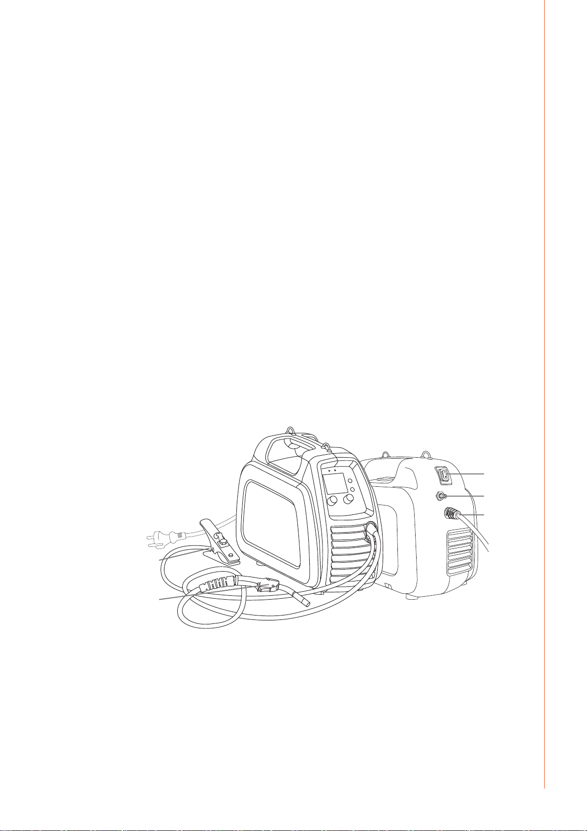
2.5 General view of the machine
5.
4.
1. Supply voltage cable
2. Main switch
3. Shielding gas hose connector
4. Welding gun and cable
5. Earth return clamp and cable
2.
3.
1.
© Kemppi Oy / 1340
5
Page 8

2.6 Cable connections
Connection to the mains
The machine is tted with a 3 m long supply voltage cable and plug. Connect the supply
voltage cable to the mains. Should you need to t an alternative plug or mains cable, ensure
installation is completed by an authorised electrician.
NOTE! The fuse size needed is 16 A delayed.
If you use an extension cable, its cross-sectional area should be at least as large as the
machines supply cable (3 x 1.5 mm²). It is recommended to use 3 x 2.5 mm² extension cable.
The maximum length for the extension cable is 100 meters.
The machine can also be used with a generator. The minimum power for the generator is
4.2 kVA, and the recommended power 8.0 kVA in order for the machine to be used at
maximum capacity.
Earth return
The welding circuit earth return cable is already connected to the machine. Clean the
workpiece surface and x the earth return clamp to the work piece in order to create a
welding circuit.
EN
Welding gun
The welding gun is already connected to the machine. The ller wire, shielding gas and
electric current is delivered to the weld inside the welding gun cable. When you press the gun
trigger, shielding gas starts to ow and ller wire feed begins. The arc ignites when the ller
wire touches the work piece. Inside the gun cable there is a factory-installed wire liner that
is best suited for welding with steel and CuSi ller wires. It can temporarily be used also with
stainless steel and aluminium wires. However, this is not recommended because of greater
friction and reduced welding performance, and it may nally lead into failure of ller wire
delivery.
If you mainly use aluminium or stainless steel ller wire, we recommend that you replace the
wire liner with a Kemppi plastic type, which is better suited for the material. For instructions
on how to change the wire liner, please refer to the Maintenance section later in this manual.
The gun neck can be rotated 360° to suit dierent welding positions. The neck is connected via
a standard clockwise screw thread. Always make sure that the neck is almost fully connected
to the bottom thread. This prevents damaging and overheating the neck.
NOTE! If you intend to use other than 0.8 mm diameter steel ller wire, change the welding gun
contact tip, gun liner, and drive roll to match the selected ller wire type and thickness.
6
MinarcMig Evo 170, Evo 200
Page 9

Shielding gas
Shielding gas is used for replacing air around the welding arc. For steel wires, use CO₂ (carbon
dioxide) or a mixture of Ar (argon) and CO₂ for shielding gas. Welding performance will be
improved when using mixed gas products. For stainless steel wires, use mixture of Ar and
CO₂ (2 %), and for aluminium and CuSi wires, use pure argon. The required ow rate of the
shielding gas is determined by the thickness of the welded sheet and the used welding power.
The machine is delivered with a 4.5 m long gas hose. Connect the supplied female snap
connector of the gas hose to the machine’s male connector. Connect the other end of the gas
hose to the gas cylinder via a suitable and approved single stage regulator valve, where outlet
ow rates can be adjusted.
NOTE! Never attempt to connect directly to a compressed gas cylinder. Always use an approved
and tested regulator and ow meter.
1.
20
15
10
2.
3.
5
l/min
4.
Connecting the gas hose to a typical welding regulator control valve
1. Connect the hose to the welding machine snap connector
2. Open the regulator valve of the gas cylinder
3. Measure the gas ow
4. Adjust the ow with the adjustment knob (10–15 lpm)
NOTE! Use a suitable shielding gas for the welding application. Always secure the gas cylinder in an
upright position with either a specially made wall rack or cylinder trolley. Always close the cylinder
valve after welding.
EN
© Kemppi Oy / 1340
7
Page 10

EN
2.7 Filler wire
The machine is delivered with the welding gun connected to the positive pole (+) making it
suitable for welding with solid steel, stainless steel, aluminium and CuSi ller wires without
extra adjustments.
2.7.1 Changing the feed roll groove
When the machine leaves factory, the feed roll groove is set for welding with ller wires of
0.8–1.0 mm diameter. The feed roll groove must be changed, if you use 0.6 mm thick ller wire.
Changing the feed roll groove
5., 8.
6.
1., 9.
3.
2., 4.
7.
1. Release the pressure control lever.
2. Switch the machine on from the main switch.
3. Press the welding gun trigger and drive the feed roll in such a position that the locking screw
is clearly visible and can be accessed.
4. Switch the power o from the main switch.
5. Release the feed roll locking screw with a 3.0 mm Allen wrench approximately half a
turn.
6. Pull the feed roll from its shaft.
7. Turn the feed roll around and reinstall it to the shaft all the way to the bottom stop, making
sure that the screw is parallel to the at area ground onto the shaft.
8. Tighten the feed roll locking screw.
9. Close the pressure control lever.
8
MinarcMig Evo 170, Evo 200
Page 11

2.7.2 Loading and threading the ller wire
1., 10.
1. Open the ller wire cabinet door by pressing the orange door latch button and installing
the ller wire spool in such a way that it rotates counter clockwise. You can use either a
5 kg (diameter 200 mm) or 1 kg (100 mm) ller wire spool with MinarcMig Evo by adding
or removing the 200 mm spool adapter.
5 kg
2.
EN
1 kg
2.
2. Attach the wire spool friction plate, lock and secure the spool.
3. Release the ller wire end from the spool, but carefully holding on to it all the times.
4. Straighten the wire end for approximately 20 cm and cut the wire in the middle of the
straightened section.
5. Smooth the sharp ller wire end
5.
© Kemppi Oy / 1340
9
Page 12

7.
9.
EN
5., 8.
6. Open the pressure control arm which then opens the feed mechanism.
7. Thread the ller wire through the wire guide to the wire liner inside the gun cable.
8. Close the feed gear and secure it with the pressure control arm. Make sure that the ller wire
runs in the feed roll groove.
9. Adjust the ller wire compression with the pressure control arm, no higher than to
the middle of the scale. If the pressure is too high, the feed rolls may remove metal
fragments from the wire surface. On the other hand, if the pressure is too low, the feed
gear slips and the wire does not feed and run smoothly.
10. Switch on the welding machine.
11. Press the welding gun trigger and wait for the ller wire to exit the welding gun.
12. Close the wire cabinet door.
NOTE! When feeding the welding wire into the gun, be sure that you are not pointing the gun at
anyone and that there isn’t anything in front of the gun. Also, do not put your ngers near the feed
rolls, because they might get trapped
2.7.3 Reversing polarity
Some ller wires are recommended to be welded with the gun in the –pole, so the polarity
should be reversed. Check the recommended polarity from the ller wire package.
10
1. Disconnect the machine from the mains.
2. Expose the terminal connections by bending the protective rubber covers away from the
terminal.
3. Remove the terminal tightening nuts and washers. Note the correct order of the washers!
4. Interchange the cables.
5. Install the washers in place and re-tightening the securing nuts.
6. Replace the rubber terminal covers. The rubber covers must always protect the terminals
during use.
MinarcMig Evo 170, Evo 200
Page 13

2.8 Controls and indicator lights
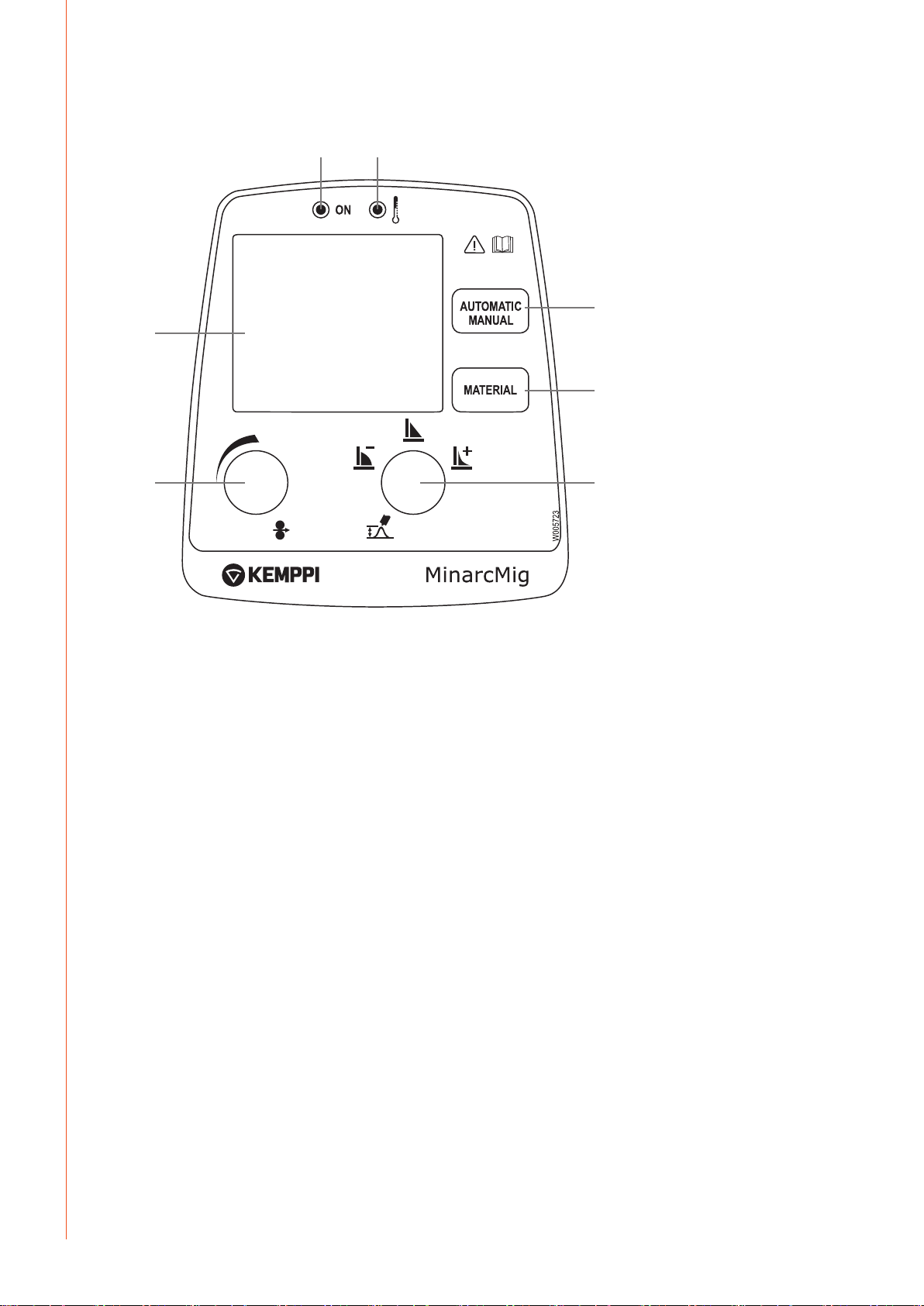
MinarcMig Evo 170 control panel
4. 5.
6.
1. 2.
U
1. Wire feed speed control
2. Welding voltage control
3. Dynamics selection control
4. Standby indicator light
5. Overheating indicator light
6. Display
Wire feed speed and welding voltage values are set and adjusted independently. Guide
parameter values can be viewed on page 15 of this manual.
The Dynamics selection control oers a choice of two settings and controls the rate of rise
of current during the welding process, when the ller wire is in contact with the weld piece.
Use Dynamics setting 'I' for lower welding parameter settings and small ller wires, and 'II' for
higher parameter settings and larger ller wires.
Indicator lights display the machine’s standby mode and inform of a possible welding duty
cycle temperature limit. When you switch the machine on, a green standby light switches on.
Simultaneously, the main switch indicator light switches on. If the machine reaches its duty
cycle limit during welding or the supply voltage is too low or too high, the welding operation
automatically switches o and the yellow overheating indicator light switches on. The light
switches o when the machine has cooled and is ready for operation again. Make sure that
there is enough space around the machine to allow fresh air to freely circulate and cool the
machine.
NOTE! Always start and stop the machine from the main switch, never use the plug as a switch!
W006095
3.
EN
© Kemppi Oy / 1340
11
Page 14
MinarcMig Evo 200 control panel
3. 4.
7.
5.
6.
EN
1.
S
Machine's control panel in automatic mode
1. Welding power control (automatic mode) OR Wire feed speed control (manual mode)
2. Arc length trimmer (automatic mode) OR Welding voltage control (manual mode)
3. Standby indicator light
4. Overheating indicator light
5. Mode selection button
6. Material selection button (automatic mode)
7. Display
In automatic mode, the welding power is adjusted according to the thickness of the material
to be welded. The machine also has a trimmer for arc length in automatic mode, which also
inuences the weld seam surface shape. There are four material options for ller wires in
automatic mode, and you can browse through them with the material selection button. In
manual mode, the wire feed speed and welding voltage are adjusted separately. Operation
mode can be changed with the mode selection button. Note that material or sheet thickness
selections made in the automatic mode are not valid in manual mode. Indicator lights display
the machine’s standby mode and inform of a possible welding duty cycle temperature limit.
When you switch the machine on, a green standby light switches on. Simultaneously, the main
switch indicator light switches on. If the machine reaches its duty cycle limit during welding
or the supply voltage is too low or too high, the welding operation automatically switches
o and the yellow overheating indicator light switches on. The light switches o when the
machine has cooled and is ready for operation again. Make sure that there is enough space
around the machine to allow fresh air to freely circulate and cool the machine.
NOTE! Always start and stop the machine from the main switch, never use the plug as a switch!
U
2.
12
MinarcMig Evo 170, Evo 200
Page 15

2.8.1 Display in automatic mode
3.
1.
4.
5.
6.
2.
Machine display in automatic mode
1. Material thickness
2. Visual material thickness and weld shape indicator
3. Operating mode reference
4. Material selection
5. Shielding gas and wire diameter recommendation
6. Wire feed graphic
7. Welding values: Wire feed speed, welding voltage and welding current
MinarcMig Evo 200 automatically sets the machine based on your input selections for plate
thickness in mm, weld shape and material type. The material thickness graphic display shows
the selected plate thickness to be welded. Your machine is automatically set for welding
following these parameters inputs.
As you make your selections you will see the displayed parameters change. For example,
as you adjust the power/plate thickness control, you will see the graphic indicating plate
thickness become thicker or thinner.
The selected operating mode and material type are also shown on the display. The display
also shows a recommendation for shielding gas and ller wire diameter for the material in
question. During welding, the graphical display shows that wire feeding is active including
the wire feed rate. Of all the welding parameters, only ller wire feed speed is visible on the
display all the time. Welding voltage and welding current are only visible on the display during
welding. The last used values remain on the display until welding is restarted or parameter
settings are changed.
When adjusting the arc length, weld shape, or voltage control, the voltage display shows
a comparative scale (-9…0…9) which will disappear from the display after a preset time
following adjustment.
7.
EN
2.8.2 Welding power adjustment in automatic mode
Adjusting the welding power according to sheet thickness aects simultaneously both wire
feed speed and amount of current delivered to the ller wire. This is a good starting point
for welding in dierent operating situations. However, welding joint type and root opening
may inuence the amount of welding power required. Select the correct welding power
using the power control, whilst viewing the graphical display of the llet weld and sheet
thickness indicator. If the llet weld’s sheets are of dierent thickness, use their average as a
default parameter and test weld. The sheet thickness display is given in millimetres and with
steel and stainless steel wires, is based on 0.8 mm ller wire diameter. When using a 0.6 mm
ller wire, set the welding power control slightly higher than the used sheet thickness and
correspondingly slightly lower with 0.9–1.0 mm wires. With aluminium wires, the welding
power adjustment is based on 1.0 mm wire diameter.
© Kemppi Oy / 1340
13
Page 16

EN
2.8.3 Arc length trimmer in automatic mode
The arc length/weld shape/voltage trimmer adjusts the length of the arc, either shorter or
longer, and aects the welding temperature. A shorter arc is colder and a longer one hotter.
The arc length trimmer also aects the arc’s welding properties and inuences weld spatter
with dierent combinations of ller wire diameters and shielding gases. The trimmer range is
-9...0...9: negative values shorten and positive values lengthen the arc. The trimmer is preset at
0 which is, in most cases, a suitable basic setting.
If the weld is too convex, the arc is too short or cold. Then adjust the arc longer or hotter by
turning the control clockwise.
If, on the other hand, you want to weld with a colder arc to prevent for example the parent
material from burning through, adjust the arc shorter by turning the control counter
clockwise. You can also adjust the welding power, if needed.
When adjusting the arc length, the cross sectional weld joint graphic on the machines display
changes correspondingly to either a more concave, at or convex weld result.
NOTE! When welding for the rst time, we recommend that you set the arc length trimmer to 0.
2.8.4 Display in manual mode
1.
2.
3.
1. Operating mode
2. Wire feed graphic
3. Welding values: wire feed speed, welding voltage and welding current
The selected 'Manual' operating mode is conrmed on the display. During welding, the wire
feed speed graphic displays the wire’s speed. Wire feed speed is the only welding parameter
always visible on the display. When adjusting welding voltage, the display shows the set value
for the voltage, and only during welding does the display show the actual value. Welding
current is visible on the display only during welding. Values for actual welding voltage and
welding current remain on the display after welding, until welding is restarted or settings are
changed.
14
MinarcMig Evo 170, Evo 200
Page 17

Arc dynamics
In Manual mode you can select from two dierent arc dynamics settings. Press Manual mode
button (Arc Dynamics control on MinarcMig 170 model) once to pre-select either arc dynamic
value I or value II. Changing between setting I and setting II will adjust the short circuit
characteristics to suit dierent welding applications.
2.8.5 Adjustments in manual mode
In manual mode, the wire feed speed and welding voltage are both adjusted separately.
Welding current and power are dened according to wire feed speed. The desired arc and
welding properties can be reached by adjusting the voltage.
2.9 MIG/MAG welding
NOTE! Welding fumes may be dangerous to your health. Ensure that there is ample ventilation
during welding! Never look at the arc without a face shield specically designed for arc welding!
Protect yourself and your surrounding area from the arc and hot welding spatter!
NOTE! Always wear protective clothing, gloves, face and eye shields suitable for welding. It is
recommended that you make practice welds before you commence welding your main work piece.
NOTE! The work piece will be very hot. Protect yourself and others at all times.
You can start welding after you have made the necessary preparation described throughout
these instructions.
Providing you ensure that the MinarcMig Evo equipment is correctly prepared and set for
the material type and joint to be welded, you will achieve exceptionally high quality welding
results.
• Ensure that the correct ller wire type and size is selected for the work piece.
• Ensure that the correct wire liner and contact tip size is tted to the welding gun.
• Ensure that the correct shielding gas type is connected and the ow rate adjusted before
welding starts.
• Ensure the earth return clamp is connected to the work piece
• Ensure that you are wearing the correct safety equipment before you start welding
- including: suitable welding clothing, the correct welding face shield with a suitable
shade welding lens, welding gloves and when necessary, a welding mask.
NOTE! Please read section 1.2.2 before proceeding further.
EN
© Kemppi Oy / 1340
15
Page 18

EN
Having checked that the MinarcMig Evo is prepared in the correct way for the welding task
ahead, and that you are wearing the necessary protective equipment, you are ready to
commence welding.
MIG/MAG welding can be performed down hand, vertically and overhead: either right to left
(Right handed operators) or left to right (left handed operators)
First, present the welding gun nozzle to a practice work piece. The gun nozzle should be
approximately 15 mm away from the surface of the work piece and weld joint. If welding a T
llet joint, the gun should be held at an angle of approximately 45 degrees, bisecting the 90
degree joint at the midway point. Starting at the right hand side of the joint (Right handed
operators only), lean the gun backwards slightly, so the gun nozzle is pointing forwards,
towards the centre of the work piece. This is called a 'pushing technique' and is suitable for
most applications.
Pull the welding gun trigger. The ller wire will move forward, and a short circuit will occur
and the arc will be established. Keeping the gun trigger depressed, the molten weld pool will
start to form. Begin to travel the gun forwards, in a controlled manner and travel speed. Not
too fast and not too slow. Providing you have correctly set your MinarcMig Evo, your welding
power should be correctly set for the material thickness and type, and the quality of your weld
deposit is now determined by your skill and technique.
The resulting weld deposit, width and shape, should be consistent in appearance and quality.
If you are welding too fast the weld bead may be too thin or even intermittent in appearance.
Try to slow your travel speed slightly and maintain an even approach to the joint. If you are
welding too slowly, you may nd the weld deposit is too heavy, the weld piece overheats and
possibly burns a hole through the plate. All that may be required to ensure a successful result
here is an increase in forward travel speed, but you may also need to reduce the power setting
slightly, to achieve the desired result.
As with all craft skills – practice will make perfect! For more info www.kemppi.com > Welding
ABC.
16
MinarcMig Evo 170, Evo 200
Page 19

2.10 Using the shoulder strap
1.
2.
3.
Using and xing the shoulder strap
The machine is delivered with a fabric shoulder strap and metal clip set. The shoulder strap
can be used as a convenient and comfortable way to transport both the machine and cables
set. There are two identical metal clips. Fix one clip to each of the metal lifting eyes, located at
the top of the machine. Adjust the shoulder strap to a comfortable length. The machine can
now be carried.
Should you also wish to transport and secure the cables set, place the cable bundle over the
strap as shown, bring the strap and remaining free clip over the top of the cable bundle and
secure to the already fastened clip. As you take the weight of the machine with the strap, the
cable set is clamped securely into position ready for transport.
NOTE! The machine should not be used when hanging from the shoulder strap.
4.
EN
3. MAINTENANCE
NOTE! Be careful when handling electrical cables!
In maintaining the unit, take into consideration the rate of use and the environment it is
used in. When the unit is used properly and serviced regularly, you will avoid unnecessary
disturbances in use and production.
3.1 Daily maintenance
• Remove welding spatters from the welding gun’s tip and check the condition of the
parts. Change damaged parts to new ones immediately. Only use original Kemppi spare
parts.
• Change damaged insulation parts to new ones immediately.
• Check the tightness of the welding gun’s and earthing cable’s connections.
• Check the condition of the supply voltage and welding cable and replace faulty cables.
• Check condition of mains and welding cables and replace damaged cables.
• See that there is enough space around the unit for ventilation.
© Kemppi Oy / 1340
17
Page 20

EN
3.2 Maintenance of the wire feed mechanism
Parts of the welding gun and wire liner
4
5
6
1 9580101
2 9591010
3 9876634
4 9876635
5 9876633
6 9876636
7 9580173
8 9591079
9 4153040
10 4307650
11 4307660
0.6 mm
0.8 mm
0.9 mm
1.0 mm
45°
0.6–1.0 mm (Fe, CuSi)
0.6–1.0 mm (Ss, Al)
12789 3
10, 11
Service the wire feed mechanism at least every time the spool is changed.
• Check the wear of the feed roll groove and change the feed roll when necessary.
• Carefully clean the welding gun wire liner with dry compressed air.
NOTE! When using compressed air pistols, ensure you are wearing adequate safety equipment
including, suitable work clothing, gloves and eye protection. Never direct compressed air pistols or
the end of the liner at your skin, face or others in the vicinity.
Cleaning the wire liner
Pressure of the feed rolls remove metal dust from the ller wire’s surface which then travels
in the wire liner inside the gun cable. If the wire liner is not cleaned, it gradually clogs up,
increasing drag, impairing wire feed performance and weld quality. Ultimately this will cause
wire feed malfunctions. Clean the liner in the following manner:
1. Remove the welding gun’s gas nozzle, contact tip and contact tip adapter.
2. With a pneumatic pistol, blow dry and ltered compressed air through the wire liner.
3. Clean the wire feed mechanism and spool housing with compressed air.
4. Reassemble the welding gun. Firmly tighten the contact tip and contact tip’s adapter.
Replacing the wire liner
If the wire liner is too worn or totally clogged, replace it with a new one according to the
following instructions. You should also replace wire liner with a plastic one, if you mainly use
stainless steel or aluminium wire.
1. Disconnect the welding gun cable from the machine as follows.
a. Disconnect the gun's power cable xing clamp by opening the screws.
b. Disconnect the gun's power cable from the machine’s pole.
c. Disconnect the connector of the trigger conductors from the machine.
d. Open the gun’s mounting nut.
e. Extract the gun gently from the machine whereupon all parts come through the
cable hole.
2. Open the mounting nut of the wire liner, which exposes the end of the wire liner.
3. Straighten the welding gun cable and withdraw the wire liner from the gun cable.
4. Push a new wire liner into the gun. Make sure that the liner enters all the way into the contact
tip’s adapter and that there is an O-ring at the machine end of the guide.
18
MinarcMig Evo 170, Evo 200
Page 21

5. Tighten the wire guide in place with the mounting nut.
6. Cut the wire guide 2 mm from the mounting nut and le the sharp edges of the cut round.
7. Reattach the gun in place and tighten the parts to spanner tightness.
3.3 Troubleshooting
Problem cause
The wire does not
move or wire feed
entangles
The main switch
indicator will not
light up
Poor welding results Several factors aect the welding quality
Overheating indicator
is illuminated
Feed rolls, wire liner or contact tips are defective
• Check wire mechanism adjustment is not too tight or too loose
• Check that the feed roll groove is not too worn
• Check that the wire liner is not blocked
• Check that the contact tip and wire liner are suitable for the wire size used
• Check that spatter is not blocking the contact tip and that the hole is not closed or damaged
• The machine has no supply voltage light
• No electricity connected to the machine
• Check the mains supply fuses
• Check the mains cable and plug
• Check that the wire feed is constant
• Check the trimming settings of welding power control and arc length
• Check the material selection setting
• Check that the earth return clamp is xed properly, xing point is clean, and both cable and its
connections are undamaged
• Check that the shielding gas is suitable for the wire material used
• Check the ow of shielding gas from the tip of the welding gun
• Supply voltage is uneven, too low or too high
The machine has overheated
Normally, this indicates that the device has reached its maximum designed operating temperature.
The thermostat has become active, switching the welding power o. Allow the unit to cool and the
machine will soon automatically reset and allow welding to restart.
• Ensure that cooling air has unrestricted ow.
• If the machine’s duty cycle has been exceeded, wait for indicator to turn o.
In certain circumstances, this light may also indicate irregularity in the supply voltage.
Too low or high supply voltage.
EN
If the machine’s malfunction is not eliminated with the above measures, contact Kemppi
service.
3.4 Storage
Store the unit in a clean and dry place. Shield it from rain, and in temperatures exceeding
+25 °C from direct exposure to sun.
3.5 Disposal of the machine
Do not dispose of electrical equipment with normal waste!
In observance of European Directive 2002/96/EC on waste electrical and electronic
equipment, and its implementation in accordance with national law, electrical equipment
that has reached the end of its life must be collected separately and taken to an appropriate
environmentally responsible recycling facility.
The owner of the equipment is obliged to deliver a decommissioned unit to a regional
collection centre, per the instructions of local authorities or a Kemppi representative. By
applying this European Directive you will improve the environment and human health.
© Kemppi Oy / 1340
19
Page 22

4. ORDERING NUMBERS
EN
MinarcMig Evo 170
MinarcMig Evo 170 AU
MinarcMig Evo 170 (Denmark)
MinarcMig Evo 200
MinarcMig Evo 200 AU
MinarcMig Evo 200 (Denmark)
Welding gun MMG22
Earthing cable and clamp
Shielding gas hose
includes gun, cables, gas hose and shoulder strap 61008170
includes gun, cables, gas hose and shoulder strap 61008170AU
includes gun, cables, gas hose and shoulder strap 61008170DK
includes gun, cables, gas hose and shoulder strap 61008200
includes gun, cables, gas hose and shoulder strap 61008200AU
includes gun, cables, gas hose and shoulder strap 61008200DK
3 m 6250220
3 m 6184003
4.5 m W001077
Shoulder strap
Consumables for wire feed mechanism
Feed roll
0.6 – 1.0 mm W000749
0.8 – 1.0 mm, knurled W001692
Pressure roll
Wire rear guide
Parts for wire spool hub
Spool flange
Spring
Wire spool lock
Consumables for MMG22 gun
Gas nozzle
Gas nozzle insulating bush
Contact tip M6
Contact tip M6
Contact tip M6
Contact tip M6
0.6 mm 9876634
0.8 mm 9876635
0.9 mm 9876633
1.0 mm 9876636
Contact tip adapter
Neck insulating ring
Wire guide
Wire guide
0.6 – 1.0 mm (Fe) 4307650
0.6 – 1.0 mm (Ss, Al) 4307660
9592163
9510112
W000651
W000728
W000980
W000727
9580101
9591010
9580173
9591079
20
MinarcMig Evo 170, Evo 200
Page 23

5. TECHNICAL DATA
MinarcMig Evo 170
Connection voltage
Connection voltage (AU)
Rated power at max. current
Supply current
Connection cable
Fuse
Output 40 °C
Welding range
No-load voltage
Idle power
Voltage steps
Power factor at 100 % ED
Efficiency at 100 % ED
Filler wires ø
Wire feed speed adjustment range
Wire spool
Shielding gases
External dimensions
Weight
Temperature class
EMC class
Degree of protection
Operating temperature range
Storage temperature range
Standards
IEC 60974-1
IEC 60974-5
IEC 60974-10
IEC 61000-3-12
1 ~ 50/60 Hz 230 V ± 15 %
1 ~ 50/60 Hz 240 V ± 15 %
35 % ED 170 A/4.8 kVA
35 % ED I
1max
100 % ED I
H07RN-F 3G1.5(1.5 mm, 3 m)
type C 16 A
35% ED 170 A/24 V
100% ED 100 A/20 V
Fe solid wire 0.6…1.0 mm
Fe cored wire 0.8…1.0 mm
max. ø 200 mm/5 kg
LxWxH 450 x 227 x 368 mm
incl. gun and cables 3.0 kg 13 kg
1e
20,3 A
10,1 A
20 A/15 V – 170 A/24 V
70 – 75 V
12 W fan o, 21 W fan on
0.1 V
0.99
80 %
1…12 m/min
CO, Ar + CO-mixed
F (155 °C)
A
IP23S
-20…+40 °C
-40…+60 °C
EN
© Kemppi Oy / 1340
21
Page 24

EN
MinarcMig Evo 200
Connection voltage
Connection voltage (AU)
Rated power at max. current
Supply current
Connection cable
Fuse
Output 40 °C
Welding range
No-load voltage
Idle power
Voltage steps
Power factor at 100 % ED
Efficiency at 100 % ED
Filler wires ø
Wire feed speed adjustment range
Wire spool
Shielding gases
External dimensions
Weight
Temperature class
EMC class
Degree of protection
Operating temperature range
Storage temperature range
Standards
IEC 60974-1
IEC 60974-5
IEC 60974-10
IEC 61000-3-12
1 ~ 50/60 Hz 230 V ± 15 %
1 ~ 50/60 Hz 240 V ± 15 %
35 % ED 200 A/6.2 kVA
35 % ED I
1max
100 % ED I
H07RN-F 3G1.5(1.5 mm, 3 m)
type C 16 A
35% ED 200 A/24 V
100% ED 120 A/20 V
Fe solid wire 0.6…1.0 mm
Fe cored wire 0.8…1.0 mm
Ss 0.8…1.0 mm
Al 1.0 mm
CuSi 0.8…1.0 mm
max. ø 200 mm/5 kg
LxWxH 450 x 227 x 368 mm
incl. gun and cables 3.0 kg 13 kg
1e
26.2 A
13.2 A
20 A/15 V – 200 A/26 V
70 – 75 V
12 W fan o, 26 W fan on
0.1 V
0.99
82 %
1…13 m/min
CO, Ar, Ar + CO-mixed
F (155 °C)
A
IP23S
-20…+40 °C
-40…+60 °C
22
MinarcMig Evo 170, Evo 200
Page 25

Page 26

KEMPPI OY
Kempinkatu 1
PL 13
FIN-15801 LAHTI
FINLAND
Tel +358 3 899 11
Telefax +358 3 899 428
export@kemppi.com
www.kemppi.com
Kotimaan myynti:
Tel +358 3 899 11
Telefax +358 3 734 8398
myynti.@kemppi.com
KEMPPI SVERIGE AB
Box 717
S-194 27 UPPLANDS VÄSBY
SVERIGE
Tel +46 8 590 783 00
Telefax +46 8 590 823 94
sales.se@kemppi.com
KEMPPI NORGE A/S
Postboks 2151, Postterminalen
N-3103 TØNSBERG
NORGE
Tel +47 33 346000
Telefax +47 33 346010
sales.no@kemppi.com
KEMPPI DANMARK A/S
Literbuen 11
DK-2740 SKOVLUNDE
DANMARK
Tel +45 4494 1677
Telefax +45 4494 1536
sales.dk@kemppi.com
KEMPPI BENELUX B.V.
Postbus 5603
NL-4801 EA BREDA
NEDERLAND
Tel +31 765717750
Telefax +31 765716345
sales.nl@kemppi.com
KEMPPI (UK) Ltd
Martti Kemppi Building
Fraser Road
Priory Business Park
BEDFORD, MK44 3WH
UNITED KINGDOM
Tel +44 (0)845 6444201
Telefax +44 (0)845 6444202
sales.uk@kemppi.com
KEMPPI FRANCE S.A.S.
65 Avenue de la Couronne des Prés
78681 EPONE CEDEX
FRANCE
Tel +33 1 30 90 04 40
Telefax +33 1 30 90 04 45
sales.fr@kemppi.com
KEMPPI GmbH
Perchstetten 10
D-35428 LANGGÖNS
DEUTSCHLAND
Tel +49 6 403 7792 0
Telefax +49 6 403 779 79 74
sales.de@kemppi.com
KEMPPI SPÓŁKA Z O.O.
Ul. Borzymowska 32
03-565 WARSZAWA
POLAND
Tel +48 22 7816162
Telefax +48 22 7816505
info.pl@kemppi.com
KEMPPI AUSTRALIA PTY LTD.
13 Cullen Place
P.O. Box 5256, Greystanes NSW 2145
SMITHFIELD NSW 2164
AUSTRALIA
Tel. +61 2 9605 9500
Telefax +61 2 9605 5999
info.au@kemppi.com
OOO KEMPPI
Polkovaya str. 1, Building 6
127018 MOSCOW
RUSSIA
Tel +7 495 739 4304
Telefax +7 495 739 4305
info.ru@kemppi.com
ООО КЕМППИ
. 1, 6
127018
Tel +7 495 739 4304
Telefax +7 495 739 4305
info.ru@kemppi.com
KEMPPI, TRADING (BEIJING) COMPANY,
LIMITED
Room 420, 3 Zone, Building B,
No.12 Hongda North Street,
Beijing Economic Development Zone,
100176 Beijing
CHINA
Tel +86-10-6787 6064
+86-10-6787 1282
Telefax +86-10-6787 5259
sales.cn@kemppi.com
肯倍贸易(北京)有限公司
中国北京经济技术开发区宏达北路12号
创新大厦B座三区420室 (100176)
电话: +86-10-6787 6064
+86-10-6787 1282
传真: +86-10-6787 5259
sales.cn@kemppi.com
KEMPPI INDIA PVT LTD
LAKSHMI TOWERS
New No. 2/770,
First Main Road,
Kazura Garden,
Neelankarai,
CHENNAI - 600 041
TAMIL NADU
Tel +91-44-4567 1200
Telefax +91-44-4567 1234
sales.india@kemppi.com
1910020
1340
www.kemppi.com
 Loading...