

Page 1
‘INSTRUCTION MANUAL
MODEL 701
ELECTRONIC RELAY
KEITHLEY INSTRUMENTS, INC.
CLEVELAND, OHIO
Page 2
i ‘.
WARRANTY .
We warrant each of our product6 to be free from defects in material
and workmanship.
Our obligation under this warranty is to repair or
replace any instrument or part thereof, except tubes, transistors,
fuses, and batteries, which, within a year after shipmqt to the
original buyer, proves defective on examination.
DAMAGE IN SHIF'MENT
Be sure to include the instrument mods1 number and serial number in
all conmnulications.
If the instrument is damaged when received, or
fails to operate properly, a claim should be filed with the carrier.
Upon receipt of the claim agent's report, we will inform you regard-
ing repair or replacement.
BEPAIRS
When returning an instrument for repair or recalibration, it should
be securely packed against shipping damage and sent to the factory,
freight prepaid.
A brief letter describing the difficulty should
accompany the instrument.
Page 3
CONTENTS
INTRODUCTION . . . . . . . . , , . . , . . . . . . .
SPECIFICATIONS . . . . .' . . . . . . . . . . . . . <
DESCRIPTION . . . . . . . . . . . . . . . . . . . .
OPERATIONS..... . . . . . . . . . . . a....
MAINTENANCE .., . . ., . . . . ..a
. . ( . . .
Schematic Diagram
Voltage and. Resistance Chart
Replaceable Parts List
SECTION
I
II
III
Iv
V
(.“..
.
Page 4
SECTION I -
INTRODUCTION
The Model 701 Electronic Relay is a sensitive direct current voltage
discriminator which actuates an Electra-magnetic relay when a predetermined voltage level is exceeded, Its action may be made
either locking or non-locking and may be wired so that it is fail-
safe for a signal which exceeds the trip point or for a signal
which decreases below the trip point,
,
The Electronic Relay features a variable "Trip Level" from 0.2 to
10 millivolts with an input,impedence of 1 megohm. The trip level
is adjustable by means of a calibrated dial on the front panel.
The instrument is normally furnished as a volts. e 8 actuated device
but can be used to control currents down to lo- amperes by shunt-
ing sn appropriate resistor across the input.
The Model 701 differs from meter type relays in that it employs a
chopper and an amplifying circuit to control to relay. It thersfore offers considerably higher sensitivity, more rugged construc-
tion, and reliable non-locking aa well'as locking operation, It
is fail-safe in that either chopper or tube failure will create
the alarm condition.
On either locking or non-locking opsration
the 701 is chatter-free. The unit
may
be mounted in the Model 7011
cabinet for convenient portability.
Page 5
SECTION II
- SPECIPICATIONS
i :
Sensitivity:
0.2 to 10 millivolts
Input Resistance:
1 megohm
Differential between operate and release:
200 microvolts
maximum
Permissible overload:
greater than 100 times
@solute zero stability:
100
microvolts
.Repeatibility and Accuracy of trip point:
2% of full scale
output : DPDT Relay 5 amps, 110 volts, non-inductive
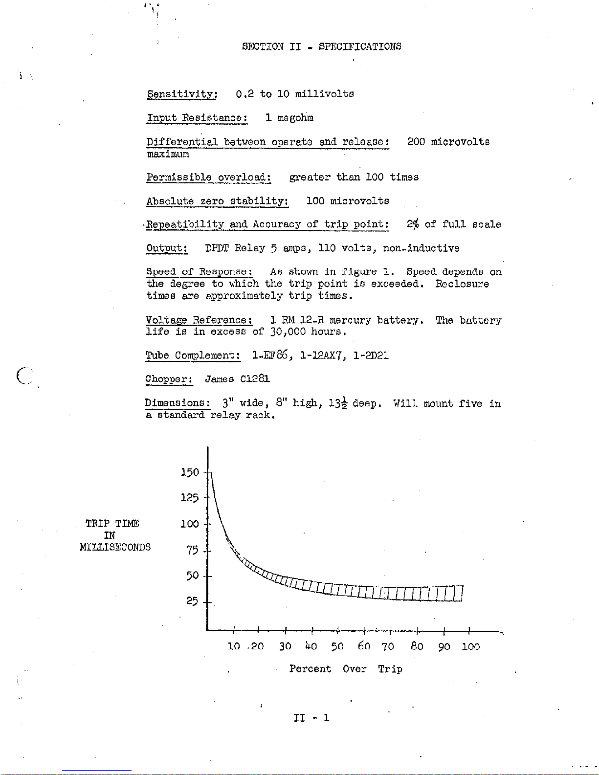
wof Response: As shown in figure 1. Speed depends on
the degree to which the trip point is exceeded. Roclosure
times are approximately trip
times.
Voltage Reference:
1 RM 12-R mercury battery. The battery
life is in excess of 30,000 hours.
Tube Complement:
l-ES%, l-X%X7, l-2D21
Chopper: James
cl281
Dimensions:
3" wide, 8" high, 134 deep. Will mount five in
a stand~relay rack.
TRIP TIME
IN
MIUISECONDS
'_
25
II7 171
--.
I
I 1 I
I
10
.20 30 40 50 60
70 80
yo loo
Percent Over Trip
II - 1
Page 6

SECTION III
- DESCRIPTION
The Model 701 Electronic Relay consists of a three stage
vacuum tube amplifier following a
60
cycle mechanical chopper.
The output of the amplifier is synchronously clemodulatcd end
filtered to provide a D. C. al.gnel at the grid of & thyratron.
The thyratron operates a relay. Positive feedback from the
thyratron grid to the input of the amplifier prevents relay
chatter.
The voltage reference consists of a mercury battery across
which is placed an accurate divider and a l$ linear potentio-
meter.
voltage.
The chopper compares the input voltage to the divider
If the input voltage is less than the divider voltage the D. C. voltage to the thyratron grid keeps the thyratron
on, if the input voltage exceeds the reference voltage the
thyratron extinguishes.
If circuit failure occurs) the signal
to the demodulator, which keeps the thyratron on, is removed
and the relay opens to indicate the alarm position.
The basic sensitivity of the instrument is 10 millivolts,
however, provision is made for mounting internal dividers
if reduced sensitivity is desired,. Also, with an input
impedance of one megohm currents down to 10-e amperes may
be measured by means of shunt resistors.
Page 7

SECTION IV
- OPERATIONS
- ,. ,,
_
._
,,I
INPUT CONNECTIONS - Connection to the input is made by means
of s. two pin connector. With the FLOATING - GROUNDED slide
switch at the rear top of the chassis in the GROUNDED position,
pin 2 is grounded to the chassis and pin 1 is the positive
terminal. The input wires should be surrounded by a shield
which is grounded to input connector shell.
If it is desired
to operate the input above ground, the slide switch should be
placed in the floating position and connection made. The shield
braid on the lead wires should be connected to the chassis, as
before. For reliable operation, it may be necessary to shield
the input circuitry.
OPERATING CONTROLS -
--
The power is turned on at the front panel.
Be sure that the instrument is wired for the proper line volt-
age. The 701 will operate satisfactorily on 50 or 60 cps. For
method of changing line voltage consult schematic.
The trip point is set by means of the large dial on the front
panel.
The RELAY OPEN light will go on when the limit is exceed-
ed.
No other operating adjustments are necessary.
NON-LOCKING OPERATION -
The instrument is normally supplied for
non-locking operation and the relay will re-close when the signal
drops more than 1% below the set point.
LOCKING OPERATION AND CONVERSION TO LOCKING OPERATION - On the
output plug at the rear of the instrument, uins 1 and 8 are
jumpered.
If this jumper is removed, the-&it will perform as
a locking relay.
To reset, pins 1 and 8 must be momentarily
shorted after the signal has fallen below the set limit,
When
units are supplied as locking relays,
a reset button, connected
across pins 1 and 8, is mounted on the front panel.
In such
units remote reset may be obtained by running wires from these
pins.~ If a non-locking unit is converted to a locking type,
reset may be provided by an external control across the reset
pins or by installing a pushbutton in the hole provided on the
panel.
REVERSE POLARITY AND LOW LIMIT OPERATION - If it is desired to
have the unit actuate an alarm when the input voltage falls below the set point it is advisable to reverse the polarity of the
leads to the chopper so that the relay will open when the signal
falls below the set point.
In this way the system is fail-safe
for low limit rather than high limit operation.
IV - 1
Page 8

If it is desired to operate on negative signals the battery
is merely reversed in its holder. Correspondingly, if it la
desired that the unit be fail-safe, the chopper lead-polarity
should be so chosen 60 that the relay opens on exceeding the
limit either from high or low as desired,
QUT~WI CONNECTIONS - The bUtpU’6 is obtainned as a DFDT set of
contacts from a relay.
The rating of the relay is 5 amperes
NON-INDUCTIVE.
If inductive loads or higher currents are to
be switched, the output should be followed by a second relay
of high enough current capacity.
IV - 2
Page 9

SECTION V - MAINTENANCE
The only maintenance required is the replacement of
the mercury standard cell every 10,000 hours. If the
highest reliability is required, it is recommended that
the vacuum tubes also be rcplaced~ on that schedule.
Page 10

^
: ‘i : :’ :
:
,.,
(1’
Page 11

MODEL 701
VOLTAGE AND RESISTANCE CHART
i ~:,
MEASUREMENTS MADE FROM TUBE PIN TO
CHASSIS GROUND \i\llTI-l CONTROL5 SET A5
,,‘:L _
FOLLOWS ;
INPUT LEADS SHORTED TO GROUND.
DIAL ADVANCED TO IO MV POSITION.
SLIDE SWITtt-i IN GROUNDED FQSITION.
USE VTVM.FaR MEASUREME:~NTS.
CM-(9 M .td
0-ti’(g M J-L)
+104v.(mfi)
+ 3.
IV. (35K4
+3.1’/(35Kd)
N.C.
+ 3, I V. ( 35Kn)
+79
V (600~~1
0-v. (O.n.1
-5.2V.
I6n)
-tqov.
(165MA)
-.Q 4 .v. (200 b’h)
N.C.
-. 83
V. (503Kh)
-67V.( 6 K a) 0-v. ( Oh),
O-V, (
On)
A,C ,
---.--. .--
[DR
12137-A
. jl
Page 12

REPL4CEABLE PARTS LIST - MODEL
701
i ‘:
circuit
Desig.
BA-1
c-101
c-102
c-103
c-104
c-105
c-1.06
c-107
c-108
c-log
DESCRIPTION
Battery - RM 12R,
Capacitor, Electrolytic, 5 mfd.
Capacitor, Disc Ceramic,
Capacitor, Same as C-102
CapacitoS, Same
Capacitor, Paper Metelized, 200 V. .l mfd.
Capacitor, Disc Ceramic,
Capacitor, Disc Ceramic;
Capacitor, Paper Metalized, 1. mfd. 200 V.
Capacitor, Paper Metalized, 1. mfd. 400 V.
1.3
V.
as C-102
15
V.
-01 mm..
600 v. 10%
.02 mfd. 600 v. 10% c22-.02
47 mmf. 600
V. lO$
PART NC.
BA-7
Cll-5
c22-.
01
c18-.l
c2Q.7
~18-1.0
c1g-1.0
-.e
(.I::
c-110
c-111 Capacitor, Electrolytic, 20 - 250 W.V.D.
c-112
c-113
c-114
c-115
cv-1
Capacitor, Electrolytic, 40 - 250 W.V.D.
Capacitor, Same as C-111
Capacitor, Electrolytic, 1000 mfd.
Capacitor, Electrolytic, Aluminum Case,
Capacitor, Disc Ceramic,
Input Connector, Amphenol
Output Connector, Amphenol
Input Plug, Amphenol 80-MC-2M
output Plug,
Chopper, James Instruments, Vibrapover - Cl281
Amphenol 57-30140
Same as C-102
80~PC-2~
57-40140
15
V.
5 mfd. 15 V.
C27-40
c27-20
Cll-1000
Cll-5
cs-32
m-33
w-1 Fuse) 1 ampere, 3 AG
250 v.
FU-8
Page 13

REPLACEABLE PARTS LIST - MODEL
701
i
Circuit
Desig.
R-101
R-J.02
R-103
R-104
R-105
R-106
R-107
R-108
R-109
R-110
R-111
R-112
R-113
R-114
R-115
R-116
R-117
R-118
R-119
R-120
R-121
R-122
R-123
R-124
R-125
DESCRIPTION
Potentiometer, 100 ohms - General Radio, 9OlVn
Potentiometer, 2K, Wire Wound, 2 W.
Resistor, Wire Wound, 10K
Resistor, Compositioll, 10 meg, &~W, 10%
Resistor, Composition, 39X. SW. 10%
Resistor, Composition, 330K. &w. 10%
Resistor, Composition, 10M. *w. 10%
Resistor, Composition, 1M. + w. 10%
Resistor, Same as R-108
Resistor, Composition, 33K. +w. 10%
Resistor, Same as R-110
Resistor, Same as R-108
Resistor, Composition, 150 ohms, *W. 10s
Resistor, Same as R-108
Resistor, Composition, 47K 4 w. lo$
Resistor, Composition, 10012.
&w. 10%
Resistor, Same as R-116
Resistor, Same as R-115
Resistor, Composition, 1K.
&w. 10s
Resistor, Composition, 100K.
$ w, 10%
Resistor, Same as R-116
Resistor, Ohmite, 20 ohms,
5 w.
10%
Resistor, Same as R-116
Resistor, Same as R-108
Resistor, 'Same as R-108
PART NO.
flp-3
RIB-16-10~
Rl-1OM
m-391(
Rl-330K
Rl-1OM
Rl-lM
Rl-33K
Rl-150
Xl-47K
Rl-lil@K
Rl-1K
Rl-100K
R4-20
Page 14

6 “‘,
kc /
Circuit
Desig.
RF-1
RF-2
m-3
m-4
w-.5
RL-1
SW-1
SW-2
TR-1
V-l
V-2 A
V-2
B
V-3
REPWXABLE PARTS LIST - MODEL 701
DESCRIPTION
Rectifier, Selenium, 130
~./65
ma
Rectifier Bridge,
130 v./65
UIR
Diode,
5ul
-
International Rectifier Corp.
Same as
W-3
Same as
RF-3
Relay, 4 P.D.T., P. & B.
MJ
1287
Switch, Toggle, S.P.S.T. - on-off
Switch, D.P.D.T.
- Floating or Ground
Transformer, ADC, A
11465
Vacuum Tube, Type EF 86, Amperex
Vacuum Tube, Type 12
AX7
Vacuum Tube, Same as V-2 A
Gas Tube, Type 2 D2 1
PART NO.
~~-18
m-7
m-15
SW-4
SW-45
lm-luur7
Ev-2D21
 Loading...