

Page 1

Model 7001 Switch System
Instruction Manual
A GREATER MEASURE OF CONFIDENCE
Page 2

W ARRANTY
Keithley Instruments, Inc. warrants this product to be free from defects in material and workmanship for a period of 1 year
from date of shipment.
Keithley Instruments, Inc. warrants the following items for 90 days from the date of shipment: probes, cables, rechargeable
batteries, diskettes, and documentation.
During the warranty period, we will, at our option, either repair or replace any product that proves to be defective.
To exercise this warranty, write or call your local Keithley representative, or contact Keithley headquarters in Cle veland, Ohio.
You will be given prompt assistance and return instructions. Send the product, transportation prepaid, to the indicated service
facility . Repairs will be made and the product returned, transportation prepaid. Repaired or replaced products are warranted for
the balance of the original warranty period, or at least 90 days.
LIMIT A TION OF W ARRANTY
This warranty does not apply to defects resulting from product modification without Keithley’s express written consent, or
misuse of any product or part. This warranty also does not apply to fuses, software, non-rechargeable batteries, damage from
battery leakage, or problems arising from normal wear or failure to follow instructions.
THIS WARRANTY IS IN LIEU OF ALL OTHER WARRANTIES, EXPRESSED OR IMPLIED, INCLUDING ANY
IMPLIED WARRANTY OF MERCHANTABILITY OR FITNESS FOR A PARTICULAR USE. THE REMEDIES PROVIDED HEREIN ARE BUYER’S SOLE AND EXCLUSIVE REMEDIES.
NEITHER KEITHLEY INSTRUMENTS, INC. NOR ANY OF ITS EMPLOYEES SHALL BE LIABLE FOR ANY DIRECT,
INDIRECT, SPECIAL, INCIDENTAL OR CONSEQUENTIAL DAMAGES ARISING OUT OF THE USE OF ITS
INSTRUMENTS AND SOFTWARE EVEN IF KEITHLEY INSTRUMENTS, INC., HAS BEEN ADVISED IN ADVANCE
OF THE POSSIBILITY OF SUCH DAMAGES. SUCH EXCLUDED DAMAGES SHALL INCLUDE, BUT ARE NOT LIMITED TO: COSTS OF REMOVAL AND INSTALLATION, LOSSES SUSTAINED AS THE RESULT OF INJURY TO ANY
PERSON, OR DAMAGE TO PROPERTY.
Keithley Instruments, Inc.
Sales Offices: BELGIUM: Bergensesteenweg 709 • B-1600 Sint-Pieters-Leeuw • 02-363 00 40 • Fax: 02/363 00 64
CHINA: Yuan Chen Xin Building, Room 705 • 12 Yumin Road, Dewai, Madian • Beijing 100029 • 8610-6202-2886 • Fax: 8610-6202-2892
FINLAND: Tietäjäntie 2 • 02130 Espoo • Phone: 09-54 75 08 10 • Fax: 09-25 10 51 00
FRANCE: 3, allée des Garays • 91127 Palaiseau Cédex • 01-64 53 20 20 • Fax: 01-60 11 77 26
GERMANY: Landsberger Strasse 65 • 82110 Germering • 089/84 93 07-40 • Fax: 089/84 93 07-34
GREAT BRITAIN: Unit 2 Commerce Park, Brunel Road • Theale • Berkshire RG7 4AB • 0118 929 7500 • Fax: 0118 929 7519
INDIA: Flat 2B, Willocrissa • 14, Rest House Crescent • Bangalore 560 001 • 91-80-509-1320/21 • Fax: 91-80-509-1322
ITALY: Viale San Gimignano, 38 • 20146 Milano • 02-48 39 16 01 • Fax: 02-48 30 22 74
KOREA: FL., URI Building • 2-14 Yangjae-Dong • Seocho-Gu, Seoul 137-130 • 82-2-574-7778 • Fax: 82-2-574-7838
NETHERLANDS: Postbus 559 • 4200 AN Gorinchem • 0183-635333 • Fax: 0183-630821
SWEDEN: c/o Regus Business Centre • Frosundaviks Allé 15, 4tr • 169 70 Solna • 08-509 04 679 • Fax: 08-655 26 10
SWITZERLAND: Kriesbachstrasse 4 • 8600 Dübendorf • 01-821 94 44 • Fax: 01-820 30 81
TAIWAN: 1FL., 85 Po Ai Street • Hsinchu, Taiwan, R.O.C. • 886-3-572-9077• Fax: 886-3-572-9031
28775 Aurora Road • Cleveland, Ohio 44139 • 440-248-0400 • Fax: 440-248-6168
1-888-KEITHLEY (534-8453) • www.keithley.com
© Copyright 2001 Keithley Instruments, Inc.
Printed in the U.S.A.
11/01
Page 3

Model 7001 Switch System Instruction Manual
©1991, Keithley Instruments, Inc.
All rights reserved.
Cleveland, Ohio, U.S.A.
Document Number 7001-901-01 Rev. H
Page 4

Manual Print History
The print history shown below lists the printing dates of all Revisions and Addenda created for this manual. The Revision
Level letter increases alphabetically as the manual undergoes subsequent updates. Addenda, which are released between Revisions, contain important change information that the user should incorporate immediately into the manual. Addenda are numbered sequentially. When a new Revision is created, all Addenda associated with the previous Revision of the manual are
incorporated into the new Revision of the manual. Each new Revision includes a revised copy of this print history page.
Revision A (Document Number 7001-901-01).........................................................................November 1991
Addendum A (Document Number 7001-901-02) ...................................................................November 1991
Addendum A (Document Number 7001-901-03) ...................................................................November 1991
Revision B (Document Number 7001-901-01)..............................................................................January 1992
Revision C (Document Number 7001-901-01) .................................................................................April 1992
Addendum C (Document Number 7001-901-02) ............................................................................. May 1992
Revision D (Document Number 7001-901-01) ................................................................................... July 1992
Addendum D (Document Number 7001-901-02)....................................................................... October 1992
Revision E (Document Number 7001-901-01)........................................................................... February 1993
Revision F (Document Number 7001-901-01) .............................................................................. August 1993
Addendum F (Document Number 7001-901-02)............................................................................. April 1995
Addendum F (Document Number 7001-901-03)........................................................................... March 1996
Addendum F (Document Number 7001-901-04)....................................................................September 1996
Revision G (Document Number 7001-901-01) ............................................................................. August 1997
Revision H (Document Number 7001-901-01).........................................................................December 2001
All Keithley product names are trademarks or registered trademarks of Keithley Instruments, Inc.
Other brand and product names are trademarks or registered trademarks of their respective holders.
Page 5

Safety Precautions
The following safety precautions should be observed before using
this product and any associated instrumentation. Although some instruments and accessories would normally be used with non-hazardous voltages, there are situations where hazardous conditions
may be present.
This product is intended for use by qualified personnel who recognize shock hazards and are familiar with the safety precautions required to avoid possible injury. Read and follow all installation,
operation, and maintenance information carefully before using the
product. Refer to the manual for complete product specifications.
If the product is used in a manner not specified, the protection provided by the product may be impaired.
The types of product users are:
Responsible body is the individual or group responsible for the use
and maintenance of equipment, for ensuring that the equipment is
operated within its specifications and operating limits, and for ensuring that operators are adequately trained.
Operators use the product for its intended function. They must be
trained in electrical safety procedures and proper use of the instrument. They must be protected from electric shock and contact with
hazardous live circuits.
Maintenance personnel perform routine procedures on the product
to keep it operating properly, for example, setting the line voltage
or replacing consumable materials. Maintenance procedures are described in the manual. The procedures explicitly state if the operator
may perform them. Otherwise, they should be performed only by
service personnel.
Service personnel are trained to work on live circuits, and perform
safe installations and repairs of products. Only properly trained service personnel may perform installation and service procedures.
Keithley products are designed for use with electrical signals that
are rated Installation Category I and Installation Category II, as described in the International Electrotechnical Commission (IEC)
Standard IEC 60664. Most measurement, control, and data I/O signals are Installation Category I and must not be directly connected
to mains voltage or to voltage sources with high transient over -voltages. Installation Category II connections require protection for
high transient over-voltages often associated with local AC mains
connections. Assume all measurement, control, and data I/O connections are for connection to Category I sources unless otherwise
marked or described in the Manual.
Exercise extreme caution when a shock hazard is present. Lethal
voltage may be present on cable connector jacks or test fixtures. The
American National Standards Institute (ANSI) states that a shock
hazard exists when voltage levels greater than 30V RMS, 42.4V
peak, or 60VDC are present.
that hazardous voltage is present in any unknown circuit before
measuring.
A good safety practice is to expect
Operators of this product must be protected from electric shock at
all times. The responsible body must ensure that operators are prevented access and/or insulated from every connection point. In
some cases, connections must be exposed to potential human contact. Product operators in these circumstances must be trained to
protect themselves from the risk of electric shock. If the circuit is
capable of operating at or above 1000 volts,
the circuit may be exposed.
For rack mount equipment in which the power cord is not accessible, in the event of fire or other catastrophic failure, the user must
provide a separate power disconnect switch.
Do not connect switching cards directly to unlimited power circuits.
They are intended to be used with impedance limited sources.
NEVER connect switching cards directly to AC mains. When connecting sources to switching cards, install protective devices to limit fault current and voltage to the card.
Before operating an instrument, make sure the line cord is connected to a properly grounded power receptacle. Inspect the connecting
cables, test leads, and jumpers for possible wear, cracks, or breaks
before each use.
When installing equipment where access to the main power cord is
restricted, such as rack mounting, a separate main input power disconnect device must be provided, in close proximity to the equipment and within easy reach of the operator.
For maximum safety, do not touch the product, test cables, or any
other instruments while power is applied to the circuit under test.
ALWAYS remove power from the entire test system and discharge
any capacitors before: connecting or disconnecting cables or jumpers, installing or removing switching cards, or making internal
changes, such as installing or removing jumpers.
Do not touch any object that could provide a current path to the common side of the circuit under test or power line (earth) ground. Always
make measurements with dry hands while standing on a dry , insulated
surface capable of withstanding the voltage being measured.
The instrument and accessories must be used in accordance with its
specifications and operating instructions or the safety of the equipment may be impaired.
Do not exceed the maximum signal levels of the instruments and accessories, as defined in the specifications and operating information, and as shown on the instrument or test fixture panels, or
switching card.
When fuses are used in a product, replace with same type and rating
for continued protection against fire hazard.
Chassis connections must only be used as shield connections for
measuring circuits, NOT as safety earth ground connections.
no conductive part of
Page 6

If you are using a test fixture, keep the lid closed while power is applied to the device under test. Safe operation requires the use of a
lid interlock.
If a screw is present, connect it to safety earth ground using the
wire recommended in the user documentation.
!
The symbol on an instrument indicates that the user should refer to the operating instructions located in the manual.
The symbol on an instrument shows that it can source or measure 1000 volts or more, including the combined effect of normal
and common mode voltages. Use standard safety precautions to
avoid personal contact with these voltages.
The
WARNING heading in a manual explains dangers that might
result in personal injury or death. Alw ays read the associated infor mation very carefully before performing the indicated procedure.
The
CAUTION heading in a manual explains hazards that could
damage the instrument. Such damage may invalidate the warranty.
Instrumentation and accessories shall not be connected to humans.
Before performing any maintenance, disconnect the line cord and
all test cables.
To maintain protection from electric shock and fire, replacement
components in mains circuits, including the power transformer, test
leads, and input jacks, must be purchased from Keithley Instruments. Standard fuses, with applicable national safety approvals,
may be used if the rating and type are the same. Other components
that are not safety related may be purchased from other suppliers as
long as they are equivalent to the original component. (Note that selected parts should be purchased only through Keithley Instruments
to maintain accuracy and functionality of the product.) If you are
unsure about the applicability of a replacement component, call a
Keithley Instruments office for information.
To clean an instrument, use a damp cloth or mild, water based
cleaner. Clean the exterior of the instrument only. Do not apply
cleaner directly to the instrument or allow liquids to enter or spill
on the instrument. Products that consist of a circuit board with no
case or chassis (e.g., data acquisition board for installation into a
computer) should never require cleaning if handled according to instructions. If the board becomes contaminated and operation is affected, the board should be returned to the factory for proper
cleaning/servicing.
11/01
Page 7

HW 9/6/01
Rev. C
ANALOG BACKPLANE
SIGNALS: Four 3-pole rows (Hi, Lo, Guard). These signals provide matrix
and multiplexer expansion between cards within one mainframe.
MAXIMUM VOLTAGE: 250V DC, 250V RMS, 350V AC peak, signal path to
signal path or signal path to chassis.
MAXIMUM CURRENT: 1A peak.
PATH ISOLATION:
>10
10
Ω, <50pF path to path (any Hi, Lo, Guard to another Hi, Lo,
Guard).
>10
10
Ω, <50pF differential (Hi to Lo or Hi, Lo to Guard).
>10
9
Ω, <75pF path to chassis.
CHANNEL CROSSTALK: <–65dB @ 1MHz (50Ωload).
BANDWIDTH: <3dB loss at 100MHz (50Ω load).
SYSTEM
CAPACITY: 2 plug-in cards per mainframe.
MEMORY: Battery backed-up storage for 100 switch patterns.
SWITCH SETTLING TIME: Automatically selected by the mainframe for
each card. Additional time from 0 to 99999.999 seconds can be added
in 1ms increments.
TRIGGER SOURCES:
External Trigger (TTL-compatible, programmable edge, 600ns mini-
mum pulse, rear panel BNC).
IEEE-488 bus (GET, *TRG)
Trigger Link
Manual (front panel)
Internal Timer, programmable from 1ms to 99999.999 seconds in 1ms
increments.
STATUS OUTPUT: Channel Ready (TTL-compatible signal, rear panel
BNC). Low going pulse (10µs typical) issued after relay settling time.
For two different switch cards, 7001 will be set to the slowest relay
settling time.
SWITCHING SEQUENCE: Automatic break-before-make.
MAINFRAME DIGITAL I/O: 4 open-collector outputs (30V maximum
pull up voltage, 100mA maximum sink current, 10Ω output impedance), 1 TTL compatible input, 1 common.
RELAY DRIVE: 700mA maximum for both card slots.
CARD SIZE: 32mm high × 114mm wide × 272mm long (1¼ in × 4½ in
× 10¾ in).
CARD COMPATIBILITY: Fully compatible with all 7XXX cards.
THROUGHPUT
EXECUTION SPEED OF SCAN LIST
1
7011 Car
d 7015 Car
d
Individual channels:
130/second 500/second
Memory setups: 125/second 450/second
TRIGGER EXECUTION TIME (maximum time from activation of
Trigger Source to start of switch open or close
2
):
SOURCE LATENCY JITTER
GET
3
200 µs <50 µs
*TRG
3
5.0 ms
Trigger Link 200 µs <13 µs
External 200 µs <13 µs
1
Rates include switch settling time of cards: 3ms for 7011 and 500µs for 7015 cards.
2
Excluding switch settling time.
3
Assuming no IEEE-488 commands are pending execution.
IEEE-488 COMMAND EXECUTION TIME
EXECUTION TIME
1
COMMAND DISPLAY OFF DISPLAY ON
OPEN (@1!1) 7.5 ms 8.5 ms
CLOS (@1!1) 7.5 ms 8.5 ms
MEM:REC M1 5.0 ms 6.0 ms
1
Measured from the time at which the command terminator is taken from the
bus to the time at which the relay begins to open or close.
IEEE-488 BUS IMPLEMENTATION
STANDARDS CONFORMANCE: Conforms to SCPI-1990, IEEE-488.2
and IEEE-488.1.
MULTILINE COMMANDS: DCL, LLO, SDC, GET, GTL, UNT, UNL,
SPE, SPD.
UNILINE COMMANDS: IFC, REN, EOI, SRQ, ATN.
INTERFACE FUNCTIONS: SH1, AH1,T5, TE0, L4, LE0, SR1, RL1, PP0,
DC1, DT1, C0, E1.
GENERAL
DISPLAY: Dual-line vacuum fluorescent.
1st line: 20-character alphanumeric.
2nd line: 32-character alphanumeric.
REAR PANEL CONNECTORS:
IEEE-488
8-pin micro DIN connector for digital I/O
8-pin micro DIN for Trigger Link
8-pin micro DIN for Trigger Link expansion
BNC for External Trigger
BNC for Channel Ready
POWER: 100V to 240V RMS , 50/60 Hz, 50VA maximum.
EMC: Complies with
to European Union Directive 89/336/EEC,
EN61326-1.
SAFETY: Conforms to European Union Directive 73/23/EEC,
EN61010-1.
EMI/RFI: Meets VDE 0871B and FCC Class B.
ENVIRONMENT:
Operating: 0°–50°C, <80% relative humidity (0°–35°C).
Storage: –25° to +65°C.
DIMENSIONS, WEIGHT: 89mm high × 216mm wide × 375mm deep
(3½ in × 8½ in × 14¾ in). Net weight 3.4kg (7½ lbs).
Specifications subject to change without notice.
7001 High Density Switch System Specifications
Page 8

Table of Contents
1 General Information
1.1 Introduction ...................................................................................................................................................... 1-1
1.2 Features.............................................................................................................................................................. 1-1
1.3 Warranty information...................................................................................................................................... 1-1
1.4 Manual addenda .............................................................................................................................................. 1-2
1.5 Safety symbols and terms ............................................................................................................................... 1-2
1.6 Specifications .................................................................................................................................................... 1-2
1.7 Inspection .......................................................................................................................................................... 1-2
1.8 Optional accessories......................................................................................................................................... 1-2
2 Card Installation
2.1 Introduction ...................................................................................................................................................... 2-1
2.2 Model 701X series card installation ............................................................................................................... 2-1
2.3 Non-701X series cards ..................................................................................................................................... 2-2
3 Getting Started
3.1 Introduction ...................................................................................................................................................... 3-1
3.2 Front and rear panel configurations.............................................................................................................. 3-1
3.2.1 Front panel controls ................................................................................................................................. 3-1
3.2.2 Rear panel.................................................................................................................................................. 3-1
3.2.3 Channel status display ............................................................................................................................ 3-4
3.3 Operation demo................................................................................................................................................ 3-7
3.3.1 Initial configuration ................................................................................................................................. 3-7
3.3.2 Close and open channels......................................................................................................................... 3-7
3.3.3 Scan channels............................................................................................................................................ 3-8
3.4 Overview of scan process.............................................................................................................................. 3-10
3.5 Initial configuration ....................................................................................................................................... 3-11
3.5.1 Switching card simulators .................................................................................................................... 3-11
3.5.2 Installing switching cards ..................................................................................................................... 3-12
3.5.3 Card type................................................................................................................................................. 3-12
3.6 Front panel operation .................................................................................................................................... 3-13
3.6.1 Close/open operation example............................................................................................................ 3-13
3.6.2 Scan operation example ........................................................................................................................ 3-15
3.7 IEEE-488.2 and SCPI basics........................................................................................................................... 3-18
3.7.1 Bus connections ...................................................................................................................................... 3-19
3.7.2 Primary address ..................................................................................................................................... 3-19
3.7.3 Abbreviated common command summary ....................................................................................... 3-19
3.7.4 Abbreviated SCPI command summary .............................................................................................. 3-19
3.7.5 Syntax rules............................................................................................................................................. 3-20
3.7.6 Programming examples ........................................................................................................................ 3-22
i
Page 9

4 Front Panel Operation
4.1 Introduction....................................................................................................................................................... 4-1
4.2 Power-up procedure ........................................................................................................................................ 4-1
4.2.1 Line power connections........................................................................................................................... 4-1
4.2.2 Power switch ............................................................................................................................................. 4-2
4.2.3 Power-up sequence .................................................................................................................................. 4-2
4.3 Display ............................................................................................................................................................... 4-3
4.3.1 Channel status display............................................................................................................................. 4-4
4.3.2 Information and error messages............................................................................................................. 4-5
4.3.3 Annunciators............................................................................................................................................. 4-5
4.4 Analog backplane ............................................................................................................................................. 4-6
4.5 Mainframe programming................................................................................................................................ 4-8
4.5.1 Channel assignments ............................................................................................................................... 4-8
4.5.2 Channel list and scan list....................................................................................................................... 4-10
4.5.3 Closing and opening channels.............................................................................................................. 4-12
4.5.4 Scanning channels .................................................................................................................................. 4-13
4.5.5 Storing channel patterns (STORE and RECALL)............................................................................... 4-20
4.6 MENU .............................................................................................................................................................. 4-22
4.6.1 SAVESETUP ............................................................................................................................................ 4-24
4.6.2 GPIB.......................................................................................................................................................... 4-25
4.6.3 DIGITAL-I/O.......................................................................................................................................... 4-26
4.6.4 TEST.......................................................................................................................................................... 4-27
4.6.5 LANGUAGE ........................................................................................................................................... 4-27
4.6.6 GENERAL................................................................................................................................................ 4-27
4.7 CARD CONFIG .............................................................................................................................................. 4-28
4.7.1 TYPE ......................................................................................................................................................... 4-29
4.7.2 #-OF-POLES ............................................................................................................................................ 4-31
4.7.3 CARD-PAIR............................................................................................................................................. 4-32
4.7.4 DELAY ..................................................................................................................................................... 4-32
4.7.5 READ-I/O-CARD .................................................................................................................................. 4-33
4.8 SCAN CONFIG............................................................................................................................................... 4-33
4.8.1 CHAN-CONTROL ................................................................................................................................. 4-35
4.8.2 SCAN CONTROL................................................................................................................................... 4-38
4.8.3 ARM CONTROL..................................................................................................................................... 4-40
4.8.4 Channel restrictions................................................................................................................................ 4-42
4.9 Digital I/O port............................................................................................................................................... 4-43
4.9.1 Controlling digital circuitry .................................................................................................................. 4-44
4.9.2 Digital input channel.............................................................................................................................. 4-46
4.9.3 I/O port connections.............................................................................................................................. 4-46
4.10 External triggering.......................................................................................................................................... 4-48
4.10.1 External trigger ....................................................................................................................................... 4-48
4.10.2 Channel ready ......................................................................................................................................... 4-49
4.10.3 External triggering example.................................................................................................................. 4-49
4.11 Trigger Link..................................................................................................................................................... 4-51
4.11.1 Asynchronous operation ....................................................................................................................... 4-51
4.11.2 Semi-synchronous operation ................................................................................................................ 4-59
4.12 DUT test system using two switching mainframes ....................................................................................4-63
4.12.1 DMM settings...........................................................................................................................................4-64
4.12.2 Switching mainframe A settings (7001)................................................................................................4-65
4.12.3 Switching mainframe B settings (7001) ................................................................................................4-66
4.12.4 Run DUT test SYSTem ............................................................................................................................4-66
4.12.5 Operation details .....................................................................................................................................4-67
ii
Page 10

5 IEEE-488 Reference
5.1 Introduction ...................................................................................................................................................... 5-1
5.2 IEEE-488 bus connections ............................................................................................................................... 5-2
5.3 Primary address selection ............................................................................................................................... 5-4
5.4 Controller programming................................................................................................................................. 5-4
5.5 Front panel aspects of IEEE-488 operation ................................................................................................... 5-5
5.5.1 Error and status messages ...................................................................................................................... 5-5
5.5.2 IEEE-488 status indicators....................................................................................................................... 5-5
5.5.3 LOCAL key ............................................................................................................................................... 5-5
5.6 Status structure ................................................................................................................................................. 5-5
5.6.1 Standard event status .............................................................................................................................. 5-7
5.6.2 Operation event status............................................................................................................................. 5-8
5.6.3 Arm event status .................................................................................................................................... 5-11
5.6.4 Sequence event status............................................................................................................................ 5-13
5.6.5 Trigger event status ............................................................................................................................... 5-15
5.6.6 Questionable event status ..................................................................................................................... 5-18
5.6.7 Queues ..................................................................................................................................................... 5-18
5.6.8 Status byte and service request (SRQ)................................................................................................. 5-18
5.7 Trigger model (IEEE-488 operation).............................................................................................................5-21
5.8 General bus commands ................................................................................................................................. 5-26
5.8.1 REN (remote enable).............................................................................................................................. 5-26
5.8.2 IFC (interface clear)................................................................................................................................ 5-27
5.8.3 LLO (local lockout) ................................................................................................................................ 5-27
5.8.4 GTL (go to local) and local.................................................................................................................... 5-27
5.8.5 DCL (device clear).................................................................................................................................. 5-27
5.8.6 SDC (selective device clear).................................................................................................................. 5-28
5.8.7 GET (group execute trigger)................................................................................................................. 5-28
5.8.8 SPE, SPD (serial polling) ....................................................................................................................... 5-28
5.9 Programming syntax ......................................................................................................................................5-29
5.10 Common commands...................................................................................................................................... 5-37
5.10.1 *CLS
5.10.2 *ESE
5.10.3 *ESE?
5.10.4 *ESR?
5.10.5 *IDN?
5.10.6 *OPC
5.10.7 *OPC?
5.10.8 *OPT?
5.10.9 *RCL
5.10.10 *RST
5.10.11 *SAV
5.10.12 *SRE
5.10.13 *SRE?
5.10.14 *STB?
5.10.15 *TRG
5.10.16 *TST?
5.10.17 *WAI
5.11 :DISPlay subsystem........................................................................................................................................ 5-67
5.12 :OUTPut subsystem ....................................................................................................................................... 5-73
5.13 [:ROUTe] subsystem ...................................................................................................................................... 5-75
5.13.1 :CLOSe <list> ........................................................................................................................................... 5-76
5.13.2 :OPEN <list>|ALL..................................................................................................................................5-78
5.13.3 :SCAN <list> ............................................................................................................................................5-79
clear status................................................................................................................................ 5-39
event status enable .................................................................................................................. 5-40
event status enable query ..................................................................................................... 5-42
event status register query ................................................................................................... 5-43
identification query............................................................................................................... 5-45
operation complete................................................................................................................. 5-46
operation complete query ................................................................................................... 5-48
option identification query.................................................................................................. 5-50
recall.......................................................................................................................................... 5-51
reset............................................................................................................................................ 5-52
save ........................................................................................................................................... 5-54
service request enable ............................................................................................................. 5-55
service request enable query................................................................................................ 5-57
status byte query.................................................................................................................... 5-58
trigger....................................................................................................................................... 5-60
self-test query ......................................................................................................................... 5-61
wait-to-continue ..................................................................................................................... 5-62
iii
Page 11

5.13.4 :FCHannels <lsit> ....................................................................................................................................5-81
5.13.5 :BBMake <b> ............................................................................................................................................5-82
5.13.6 :SCHannel <b> .........................................................................................................................................5-82
5.13.7 :CPAir <b>................................................................................................................................................5-83
5.13.8 <CTYPe <name>......................................................................................................................................5-84
5.13.9 :POLE <NRf> ...........................................................................................................................................5-85
5.13.10 :STIMe <n> ...............................................................................................................................................5-87
5.13.11 :SAVE M<num>.......................................................................................................................................5-88
5.13.12 :RECall M<num>.....................................................................................................................................5-88
5.14 Sense Subsystems ........................................................................................................................................... 5-91
5.15 :SOURce subsystem........................................................................................................................................ 5-93
5.16 :STATus subsystem ........................................................................................................................................ 5-95
5.16.1 [:EVENt]? ..................................................................................................................................................5-96
5.16.2 :ENABle <NRf>......................................................................................................................................5-100
5.16.3 :PTRansition <NRf> ..............................................................................................................................5-104
5.16.4 :NTRansition <NRf> .............................................................................................................................5-109
5.16.5 :CONDition?...........................................................................................................................................5-111
5.16.6 :PREset.....................................................................................................................................................5-112
5.16.7 :QUEue commands................................................................................................................................5-113
5.17 :SYSTem Subsystem ......................................................................................................................................5-117
5.17.1 :PRESet ....................................................................................................................................................5-117
5.17.2 :POSetup <name>..................................................................................................................................5-117
5.17.3 :VERSion?................................................................................................................................................5-118
5.17.4 :ERRor?....................................................................................................................................................5-119
5.18 Trigger subsystem ........................................................................................................................................ 5-121
5.18.1 :INITiate commands..............................................................................................................................5-123
5.18.2 :ABORt ....................................................................................................................................................5-124
5.18.3 :IMMediate .............................................................................................................................................5-124
5.18.4 :COUNt <n> ...........................................................................................................................................5-125
5.18.5 :DELay <n>.............................................................................................................................................5-127
5.18.6 :SOURce <name>...................................................................................................................................5-128
5.18.7 :TIMer <n>..............................................................................................................................................5-130
5.18.8 :SIGNal ....................................................................................................................................................5-131
5.18.9 TCONfigure commands .......................................................................................................................5-131
6 Theory of Operation
6.1 Introduction....................................................................................................................................................... 6-1
6.2 Overall functional description .........................................................................................................................6-1
6.3 Control function.................................................................................................................................................6-3
6.3.1 Reset circuitry............................................................................................................................................ 6-3
6.3.2 Address decoding..................................................................................................................................... 6-3
6.3.3 Memory...................................................................................................................................................... 6-3
6.4 Relay control circuitry.......................................................................................................................................6-5
6.4.1 Backplane interface................................................................................................................................... 6-5
6.4.2 Switch card interface................................................................................................................................ 6-7
6.4.3 ID data circuits .......................................................................................................................................... 6-7
6.4.4 Relay control.............................................................................................................................................. 6-9
6.4.5 Power-on safeguard ................................................................................................................................. 6-9
6.4.6 Display board circuitry............................................................................................................................ 6-9
6.4.7 External control signals.......................................................................................................................... 6-11
6.4.8 IEEE-488 interface................................................................................................................................... 6-11
6.4.9 Power supplies........................................................................................................................................ 6-11
iv
Page 12

7 Maintenance
7.1 Introduction ...................................................................................................................................................... 7-1
7.2 Service options................................................................................................................................................... 7-1
7.3 Handling and cleaning .....................................................................................................................................7-2
7.3.1 Backplane board ........................................................................................................................................ 7-2
7.3.2 Static-sensitive devices ............................................................................................................................. 7-2
7.4 Routine maintenance ........................................................................................................................................7-3
7.4.1 Line voltage selection .............................................................................................................................. 7-3
7.4.2 Changing the fuse .................................................................................................................................... 7-3
7.4.3 Changing the battery ................................................................................................................................7-3
7.4.4 Changing firmware.................................................................................................................................. 7-4
7.5 Disassembly of the instrument........................................................................................................................7-4
7.5.1 Removal of the case.................................................................................................................................. 7-4
7.5.2 Removal of individual boards................................................................................................................ 7-5
7.5.3 Replacement of the case ...........................................................................................................................7-7
7.6 Diagnostics .........................................................................................................................................................7-8
7.6.1 Preparations for running the diagnostics ............................................................................................. 7-8
7.6.2 Initial power-up test ................................................................................................................................ 7-8
7.6.3 Non-volatile memory test ........................................................................................................................7-8
7.6.4 Built-in-tests .............................................................................................................................................. 7-9
7.6.5 Display test
7.6.6 Display test
7.6.7 Display test Ñ char set ...........................................................................................................................7-11
7.7 Test description and notes .............................................................................................................................7-11
7.7.1 Initial power-up test .............................................................................................................................. 7-11
7.7.2 Non-volatile memory tests.................................................................................................................... 7-12
7.7.3 Built-in-tests .............................................................................................................................................7-12
7.8 Troubleshooting .............................................................................................................................................. 7-14
7.8.1 Digital board ........................................................................................................................................... 7-14
7.8.2 Display board.......................................................................................................................................... 7-15
7.8.3 Power supply........................................................................................................................................... 7-15
7.8.4 Micro DIN board .................................................................................................................................... 7-16
7.8.5 Backplane board ..................................................................................................................................... 7-16
7.8.6 BNC board................................................................................................................................................ 7-16
keys................................................................................................................................ 7-10
patterns ......................................................................................................................... 7-10
8 Replaceable Parts
8.1 Introduction ...................................................................................................................................................... 8-1
8.2 Electrical components list ................................................................................................................................ 8-1
8.3 Mechanical parts ............................................................................................................................................... 8-1
8.4 Ordering information .......................................................................................................................................8-1
8.5 How to obtain factory service ......................................................................................................................... 8-1
8.6 Document list ..................................................................................................................................................... 8-2
Appendices
A Interface Function Codes ............................................................................................................................... A-1
B ASCII Character Codes and IEEE-488 Multiline Interface Command Messages ................................... B-1
C Controller Programs ....................................................................................................................................... C-1
D IEEE-488 Bus Overview.................................................................................................................................. D-1
E IEEE-488 Conformance Information ............................................................................................................. E-1
F SCPI Conformance Information..................................................................................................................... F-1
v
Page 13

List of Illustrations
2 Card Installation
Figure 2-1 Multi-pin card installation...................................................................................................................... 2-3
Figure 2-2 Screw terminal card installation ............................................................................................................ 2-4
3 Getting Started
Figure 3-1 Model 7001 front panel............................................................................................................................ 3-2
Figure 3-2 Model 7001 rear panel ............................................................................................................................. 3-3
Figure 3-3 Channel status display ............................................................................................................................ 3-5
Figure 3-4 Channel assignments (matrix cards)..................................................................................................... 3-5
Figure 3-5 Channel assignments (non-matrix type cards).................................................................................... 3-6
Figure 3-6 Simplified model of scan operation..................................................................................................... 3-10
4 Front Panel Operation
Figure 4-1 Display format.......................................................................................................................................... 4-3
Figure 4-2 Channel status display ............................................................................................................................ 4-4
Figure 4-3 Interpreting channel status display....................................................................................................... 4-4
Figure 4-4 Model 7001 analog backplane ................................................................................................................ 4-7
Figure 4-5 Matrix row connections to backplane ................................................................................................... 4-7
Figure 4-6 Channel assignments (non-matrix type cards).................................................................................... 4-8
Figure 4-7 Channel assignments (matrix cards)..................................................................................................... 4-9
Figure 4-8 Trigger Model (Front panel scan operation)...................................................................................... 4-14
Figure 4-9 Digital I/O port simplified schematic.................................................................................................. 4-43
Figure 4-10 Sample externally powered relay ........................................................................................................ 4-46
Figure 4-11 Digital I/O port .......................................................................................................................................4-47
Figure 4-12 Digital I/O connections using trigger link cable............................................................................... 4-48
Figure 4-13 External triggering connectors (BNC)................................................................................................. 4-48
Figure 4-14 External trigger and asynchronous Trigger Link Input pulse specifications................................ 4-48
Figure 4-15 Channel ready and asynchronous Trigger Link Output pulse specifications .............................. 4-49
Figure 4-16 DUT test system ..................................................................................................................................... 4-50
Figure 4-17 External trigger connectors................................................................................................................... 4-50
Figure 4-18 Trigger link connectors.......................................................................................................................... 4-51
Figure 4-19 DUT test system ..................................................................................................................................... 4-52
Figure 4-20 Trigger Link connections (asynchronous example #1)..................................................................... 4-52
vii
Page 14

Figure 4-21 Operation model for asynchronous Trigger Link example #1 ........................................................ 4-54
Figure 4-22 Connections using Trigger Link adapter ............................................................................................ 4-55
Figure 4-23 DUT test system (asynchronous example #2) .................................................................................... 4-56
Figure 4-24 Trigger Link connections (asynchronous example #2) ..................................................................... 4-56
Figure 4-25 Operation model for asynchronous Trigger Link example #2 ........................................................ 4-58
Figure 4-26 Semi-synchronous trigger link pulse specifications .......................................................................... 4-59
Figure 4-27 Typical semi-synchronous mode connections.................................................................................... 4-59
Figure 4-28 Trigger Link connections (semi-synchronous example)................................................................... 4-60
Figure 4-29 Operation model for semi-synchronous Trigger Link example ...................................................... 4-62
Figure 4-30 DUT test system.......................................................................................................................................4-63
Figure 4-31 Trigger link connections .........................................................................................................................4-64
Figure 4-32 Digital multimeter flowchart .................................................................................................................4-68
Figure 4-33 Digital multimeter block diagram.........................................................................................................4-69
5 IEEE-488 Reference
Figure 5-1 IEEE-488 connector................................................................................................................................... 5-2
Figure 5-2 IEEE-488 connections............................................................................................................................... 5-2
Figure 5-3 IEEE-488 connector location.................................................................................................................... 5-3
Figure 5-4 Contact assignments ................................................................................................................................ 5-3
Figure 5-5 Model 7001 status register structure...................................................................................................... 5-6
Figure 5-6 Standard event status............................................................................................................................... 5-7
Figure 5-7 Operation event status............................................................................................................................. 5-9
Figure 5-8 Arm event status..................................................................................................................................... 5-11
Figure 5-9 Sequence event status ............................................................................................................................ 5-14
Figure 5-10 Trigger event status................................................................................................................................ 5-16
Figure 5-11 Status byte and service request (SRQ)................................................................................................. 5-19
Figure 5-12 Trigger model (IEEE-488 bus operation)..............................................................................................5-22
Figure 5-13 Standard Event Status Enable Register ............................................................................................... 5-41
Figure 5-14 Standard Event Status Register ............................................................................................................ 5-44
Figure 5-15 Service Request Enable Register........................................................................................................... 5-56
Figure 5-16 Status Byte Register................................................................................................................................ 5-59
Figure 5-17 Operation Event Register ...................................................................................................................... 5-98
Figure 5-18 Trigger Event Register ........................................................................................................................... 5-98
Figure 5-19 Arm Event Register ................................................................................................................................ 5-99
Figure 5-20 Sequence Event Register...................................................................................................................... 5-100
Figure 5-21 Operation Event Enable Register ....................................................................................................... 5-102
Figure 5-22 Trigger Event Enable Register ............................................................................................................ 5-102
Figure 5-23 Arm Event Enable Register ..................................................................................................................5-103
Figure 5-24 Sequence Event Enable Register..........................................................................................................5-103
Figure 5-25 Operation Transition Filter...................................................................................................................5-105
Figure 5-26 Trigger Transition Filter .......................................................................................................................5-106
Figure 5-27 Arm Transition Filter ............................................................................................................................5-107
Figure 5-28 Sequence Transition Filter................................................................................................................... 5-108
viii
Page 15

6 Theory of Operation
Figure 6-1 Model 7001 system block diagram....................................................................................................... 6-2
Figure 6-2 Block diagram
Figure 6-3 Backplane interface simplified schematic........................................................................................... 6-6
Figure 6-4 Timing diagram
Figure 6-5 Block diagram
Figure 6-6 Timing diagram, IDCLK and IDDATA .............................................................................................. 6-8
Figure 6-7 Start and stop sequences ....................................................................................................................... 6-9
Figure 6-8 Display board block diagram ............................................................................................................. 6-10
Figure 6-9 BNC board block diagram .................................................................................................................. 6-11
Figure 6-10 Micro DIN board block diagram........................................................................................................ 6-12
digital circuitry and memory................................................................................ 6-4
backplane interface WRITE................................................................................ 6-7
backplane interface (one slot) ............................................................................... 6-8
7 Maintenance
Figure 7-1 First pattern for display test................................................................................................................ 7-11
Appendices
Figure D-1 IEEE-488 bus configuration ................................................................................................................... D-2
Figure D-2 IEEE-488 handshake sequence ............................................................................................................... D-3
Figure D-3 Command codes...................................................................................................................................... D-7
ix
Page 16

List of Tables
3 Getting Started
Table 3-1 Abbreviated common command summary ....................................................................................... 3-19
Table 3-2 Abbreviated SCPI command summary .............................................................................................. 3-20
4 Front Panel Operation
Table 4-1 Error and status messages ...................................................................................................................... 4-5
Table 4-2 MENU structure ..................................................................................................................................... 4-23
Table 4-3 Default conditions .................................................................................................................................. 4-25
Table 4-4 CARD CONFIG MENU structure ....................................................................................................... 4-29
Table 4-5 TYPE assignments .................................................................................................................................. 4-30
Table 4-6 CONFIGURE SCAN menu structure .................................................................................................. 4-33
5 IEEE-488 Reference
Table 5-1 IEEE contact designations ....................................................................................................................... 5-3
Table 5-2 HP BASIC 4.0 IEEE-488 statements ....................................................................................................... 5-5
Table 5-3 General bus commands and associated BASIC statements ............................................................. 5-26
Table 5-4 IEEE-488.2 common commands and queries ..................................................................................... 5-38
Table 5-5 Default conditions .................................................................................................................................. 5-53
Table 5-6 DISPlay command summary................................................................................................................ 5-67
Table 5-7 OUTPut command summary ............................................................................................................... 5-73
Table 5-8 ROUTe command summary................................................................................................................. 5-75
Table 5-9 SENSe command summary .................................................................................................................. 5-91
Table 5-10 SOURce command summary ............................................................................................................... 5-93
Table 5-11 STATus command summary................................................................................................................ 5-95
Table 5-12 SYSTem command summary ............................................................................................................. 5-117
Table 5-13 Trigger command summary............................................................................................................... 5-121
7 Maintenance
Table 7-1 Power supply checks ............................................................................................................................. 7-16
xi
Page 17

8 Replaceable Partsd
Table 8-1 Digital board, parts list .............................................................................................................................8-3
Table 8-2 Digital board, parts list .............................................................................................................................8-5
Table 8-3 Micro DIN board, parts list ......................................................................................................................8-7
Table 8-4 Backplane board, parts list .......................................................................................................................8-9
Table 8-5 BNC board, parts list .................................................................................................................................8-1
Appendices
Table A-1 Model 7001 interface function codes ................................................................................................... A-2
Table C-1 BASIC statements necessary to send bus commands ........................................................................ C-3
Table D-1 IEEE-488 bus command summary ....................................................................................................... D-5
Table D-2 Hexadecimal and decimal command codes ....................................................................................... D-8
Table D-3 Typical addressed command sequence ............................................................................................... D-8
Table D-4 Typical common command sequence ................................................................................................. D-9
Table D-5 IEEE command groups .......................................................................................................................... D-9
Table E-1 IEEE-488 documentation requirements................................................................................................ E-1
Table F-1 Syntax of SCPI confirmed commands implemented by Model 7001............................................... F-1
Table F-2 Syntax of non-SCPI commands implemented by Model 7001.......................................................... F-5
xii
Page 18

1
General Information
1.1 Introduction
This section contains general information about the
Model 7001 Switch System.
1.2 Features
1.3 Warranty Information
1.4 Manual Addenda
1.5 Safety Symbols and Terms
1.6 SpeciÞcations
1.7 Inspection
1.8 Optional Accessories
1.2 Features
Some important Model 7001 features include:
¥ Analog Backplane
connect the rows or banks of a Model 701X series
card installed in one slot to the rows or banks of a
second Model 701X series card installed in the other slot.
¥ Close/Open or Scan
close and/or open one or more channels, or scan
through a speciÞed list of channels.
¥ Channel Status Display
play monitors the state (closed or open) of all available channels.
¥ Memory
open and closed channels) and 10 customized instrument setups can be saved in memory for later
recall.
¥ IEEE-488 Bus
IEEE-488.2 and SCPI standards.
¥ Trigger Link
more versatile and precise external triggering. This
is in addition to the standard in/out BNC external
triggering technique.
Up to 100 channel patterns (pattern of
Can be used to internally
The Model 7001 can simply
The real-time status dis-
Bus operation conforms to the
New trigger concept to provide
¥ High Density Switching
mainframe using two switching cards.
¥ Switching Cards
cards designed speciÞcally for the Model 7001 (i.e.
Models 7011, 7012 and 7013), you can use the
switching cards that were originally designed for
the Keithley Models 705 and 706 scanners.
Up to 80 channels per
In addition to the switching
1.3 Warranty information
Warranty information is located on the inside front
cover of this instruction manual. Should your Model
7001 require warranty service, contact the Keithley representative or authorized repair facility in your area for
further information. When returning the instrument
for repair, be sure to Þll out and include the service
1-1
Page 19

General Information
form at the back of this manual in order to provide the
repair facility with the necessary information.
1.4 Manual addenda
Any improvements or changes concerning the instrument or manual will be explained in an addendum included with the manual. Be sure to note these changes
and incorporate them into the manual.
1.5 Safety symbols and terms
The following symbols and terms may be found on an
instrument or used in this manual.
The symbol on an instrument indicates that the
user should refer to the operating instructions located
in the instruction manual.
!
1.7 Inspection
The Model 7001 was carefully inspected, both electrically and mechanically before shipment. After unpacking all items from the shipping carton, check for any
obvious signs of physical damage that may have occurred during transit. Report any damage to the shipping agent immediately. Save the original packing
carton for possible future reshipment. The following
items are included with every Model 7001 order:
¥ Model 7001 Switch System
¥ Model 7001 Instruction Manual
¥ Accessories as ordered.
If an additional instruction manual is required, order
the manual package, Keithley part number 7001-901-
00. The manual package includes an instruction manual and any pertinent addenda.
1.8 Optional accessories
The symbol on an instrument shows that high
voltage may be present on the terminal(s). Use standard safety precautions to avoid personal contact with
these voltages.
The WARNING heading used in this manual explains
dangers that might result in personal injury or death.
Always read the associated information very carefully
before performing the indicated procedure.
The CAUTION heading used in this manual explains
hazards that could damage the scanner card. Such
damage may invalidate the warranty.
1.6 Specifications
Model 7001 speciÞcations may be found at the front of
this manual.
The following accessories are available from Keithley
for use with the Model 7001.
Model 4288-1 Single Fixed Rack Mount Kit; mounts a
single Model 7001 in a standard 19-inch rack.
Model 4288-2 Dual Fixed Rack Mount Kit; mounts
two Model 7001s side-by-side in a standard 19-inch
rack.
Model 4288-3 Dual Fixed Rack Mount Kit; mounts
one Model 7001 and a Model 199 DMM side-by-side in
a standard 19-inch rack.
Model 8502 Trigger Link Adapter; allows you to con-
nect the Trigger Link of the Model 7001 to an instrument that uses the standard BNC (In/Out) external
triggering technique.
1-2
Page 20

General Information
Models 8501-1 and 8501-2 Trigger Link Cables: The
Model 8501-1 is one meter in length, and the Model
8501-2 is two meters in length.
Model 7007 Shielded IEEE-488 Cables: Connects the
Model 7001 to the IEEE-488 bus using shielded cables
to reduce electromagnetic interference (EMI). The
Model 7007-1 is one meter in length and has an EMI
shielded IEEE-488 connector at each end. The Model
7007-2 is identical to the Model 7007-1, but is two
meters in length.
1-3
Page 21

2
Card Installation
ATTENTION FIRST TIME USERS
If you are a first time user , it is recommended that you
perform the operation demo in Section 3, Getting
Started (paragraph 3.3) before installing any switching cards into the mainframe. This demo will acquaint
you with basic front panel operation.
WARNING
The procedures in this section are intended for use only by qualiÞed service personnel. Do not perform these
procedures unless qualiÞed to do so.
Failure to recognize and observe normal safety precautions could result
in personal injury or death.
2.1 Introduction
The Model 7001 is designed to be used with the Model
701X series switch cards (i.e. Model 7011, 7012, and
7013), and with cards that were originally designed to
be used with the Keithley Model 705/706 scanners.
2.3 Non-701X series card installation: Explains how
to install cards designed for the Model 705/706 scanner in the Model 7001.
2.2 Model 701X series card installation
WARNING
Turn off power from all instrumentation (including the Model 7001 mainframe) and disconnect their line
cords. Make sure all power is removed and stored energy in external
circuitry is discharged.
NOTE
Installation procedures in this section are organized as
follows:
2.2 Model 701X series card installation: Explains how
to install a Model 701X series card (such as the
Model 7011, 7012, or 7013) card in the Model 7001.
If using the screw terminal connector
card, make sure your external circuitry is wired to the card (as explained in
the instruction manual for the card)
before installing the card assembly in
the Model 7001 mainframe.
2-1
Page 22

Card Installation
CAUTION
To prevent contamination to the
switch card that could degrade
performance, only handle the card
assembly by the edges and shields. If
contamination occurs, clean the card
as explained in its instruction manual.
Card installation
Perform the following steps to install the card assembly in the Model 7001 mainframe:
1. Mate the connector card to the relay card if they are
separate. Make sure to handle the cards by the edges and shields to prevent contamination.
2. Facing the rear panel of the Model 7001, select the
slot (CARD 1 or CARD 2) that you wish to install
the card in.
3. Referring to Figure 2-1 or Figure 2-2, feed the card
assembly into the desired slot such that the edges
of the relay card ride in the rails.
4. With the ejector arms in the unlocked position,
push the card assembly into the mainframe until
the arms engage into the ejector cups. Then push
both arms inward to lock the card all the way into
mainframe.
5. For the multi-pin connector card, install the screw
shown in Figure 2-1.
Notes:
1. Once a Model 701X series card is installed in the
mainframe, the Model 7001 automatically identiÞes it on power up. This ID allows the Model 7001
to conÞgure itself for proper operation.
2. When a Model 701X series card is installed, the slot
assignment (Card TYPE) is performed automatically on power-up. A slot assignment change could
make a channel that is currently included in the
Scan List and/or a Channel Pattern unavailable.
The unavailable channel causes the Scan List and/
or the affected Channel Pattern to clear (see paragraph 4.5.2 and 4.5.5 for details).
Card removal
To remove the card assembly, Þrst unlock it by pulling
the ejector arms outward, then pull the card assembly
out of the mainframe. Remember to handle the card assembly by the edges and shields to avoid contamination that could degrade performance.
2.3 Non-701X series cards
WARNING
Turn off power from all instrumentation (including the Model 7001 mainframe) and disconnect their line
cords. Make sure all power is removed and stored energy in external
circuitry is discharged.
NOTE
If using a card that requires connections to be made on the card, make
sure your external circuitry is wired to
the card (as explained in the instruction manual for the card) before installing the card in the Model 7001
mainframe.
CAUTION
To prevent contamination to the
switch card that could degrade performance, only handle the card by
the edges. If contamination occurs,
clean the card as explained in its instruction manual.
Card installation
Perform the following steps to install the card in the
Model 7001 mainframe:
1. Facing the rear panel of the Model 7001, select the
slot (CARD 1 or CARD 2) that you wish to install
the card in.
2. Using Figure 2-1 or Figure 2-2 as a guideline, feed
the card into the desired slot such that the edges of
the card ride in the rails.
3. With the ejector arms in the unlocked position,
push the card assembly into the mainframe until
the arms engage into the ejector cups. Then push
both arms inward to lock the card into the mainframe.
2-2
Page 23
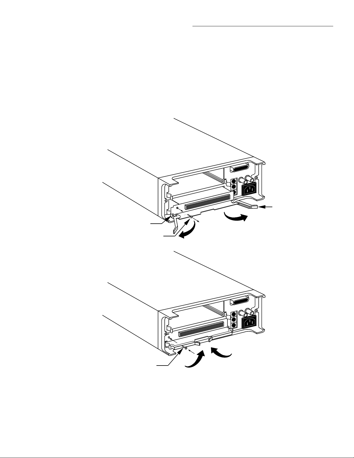
Card Installation
NOTE
The Model 7001 cannot automatically
identify non-701X cards. After the
mainframe is powered up, you must
enter the model number using the
TYPE menu item in the CARD CONFIG MENU (see paragraph 3.5.3 in
Getting Started).
Card removal
To remove the card, Þrst unlock it by pulling the ejector
arms outward, then pull the card out of the mainframe.
Remember to handle the card by the edges to avoid
contamination that could degrade performance.
Ejector Arms (2)
Figure 2-1
Multi-pin card installation
Ejector Cup
Screw
Screw
2-3
Page 24
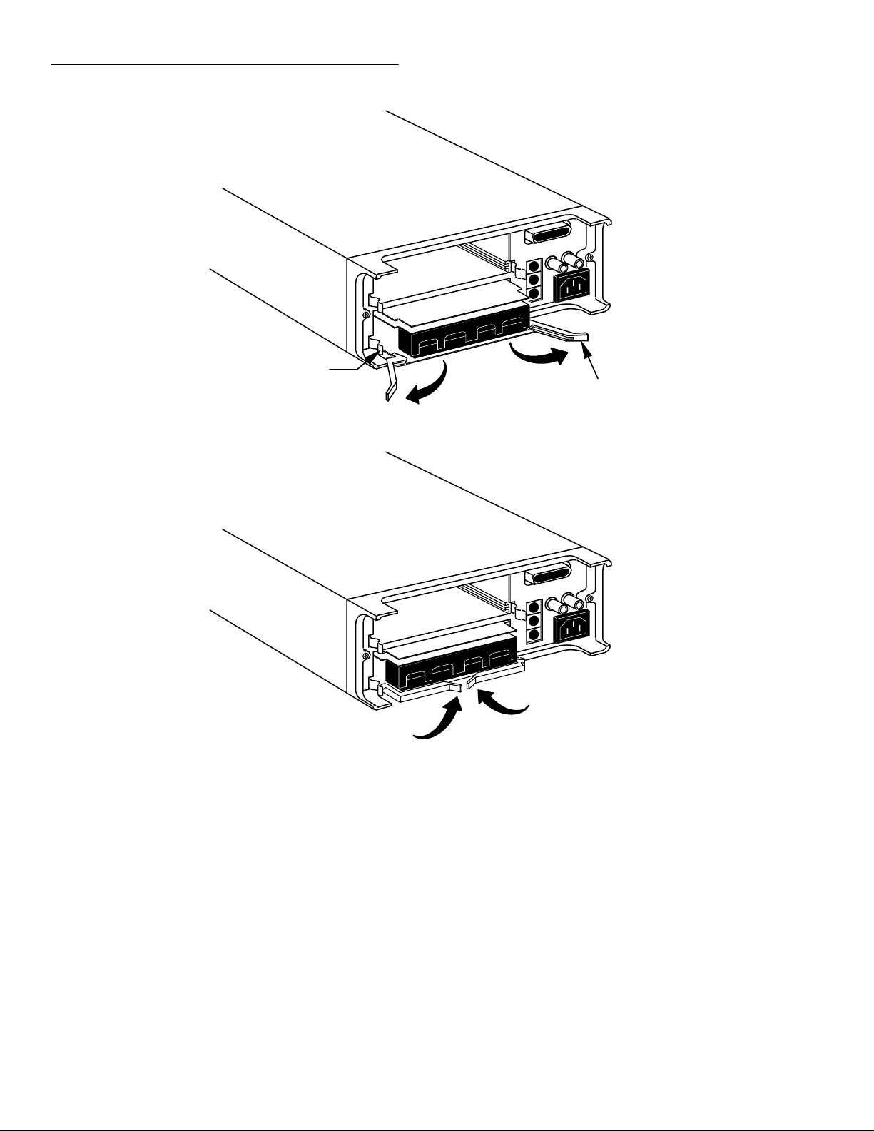
Card Installation
Ejector Cup
Ejector Arms (2)
Figure 2-2
Screw terminal card installation
2-4
Page 25

3
Getting Started
3.1 Introduction
This section contains introductory information on using your Model 7001 Switch System. For detailed front
panel and IEEE-488 bus operation, refer to Sections 4
and 5 respectively.
The information in this section is arranged as follows:
3.2 Front and rear panel configuration: Summarizes
the controls and display on the front panel of the
instrument.
3.3 Operation demo: Demonstrates basic operation
using the built-in 40-channel multiplexer simulator. Recommended for first time users.
3.4 Overview of scan process: Provides a brief over-
view of the scan process.
3.5 Initial configuration: Goes over some initial con-
figuration information that should be considered
before operating the instrument.
3.6 Front panel operation: Demonstrates basic front
panel operation through the use of simple examples.
3.7 IEEE-488.2 and SCPI basics: Discusses funda-
mental information concerning operation over
the IEEE-488 bus.
3.2 Front and rear panel
configurations
3.2.1 Front panel controls
The front panel controls of the Model 7001 are shown
in Figure 3-1. This figure includes important abbreviated information that should be reviewed before operating the instrument. Notice that some of the controls are
dual-function, rocker-action type keys. These include
SCAN/CARD CONFIGURATION, DELETE/INSERT,
EXIT/ENTER and / .
3.2.2 Rear panel
The rear panel of the Model 7001 is shown in Figure 3-
2. This figure also includes important abbreviated
information that should be reviewed before operating
the instrument.
3-1
Page 26
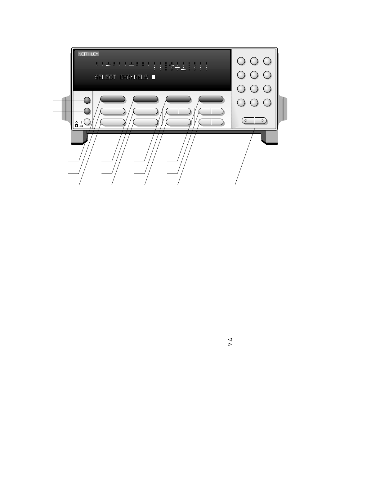
Getting Started
1
2
INFO
LOCAL
POWER
3
4
5
6
1
INFO
Displays on-line help
information. Press
again (or EXIT) to
cancel message.
LOCAL
2
Cancels remote, restores
front panel control.
POWER
3
0 =off
1 = on
OPEN A LL
4
Opens all channels of
both slots. Also, aborts
a scan that is in
progress and places
7001 in idle state.
SCAN L IST
5
Toggles between Scan
List and Channel List
CLEA R LI ST
6
Clears the displayed
Channel List or Scan
List.
STEP
7
Takes 7001 out of idle
state and steps through
Scan List
1234567891012345678910
7
8
9
CARD 1 CARD 2
OPEN ALL
SCAN LIST
CLEAR LIST
STEP
MEMORY
STORE
RECALL
10
11
12
STORE
8
Stores channel pattern at a
specified memory location.
RECALL
9
Restores 7001 to a channel
pattern stored at a specified
memory location.
OPE N
10
Opens the specified (displayed)
channels in Channel List.
SCAN CONFIGURATION
11
Enables CONFIGURE SCAN
MENU :
CHAN-CONTROL
SCAN-CONTROL
ARM-CONTROL
CHAN-RESTRICTIONS
7001 SWITCH SYSTEM
OPEN
CONFIGURATION
SCAN CARD
MENU
CLOSE
DELETE INSERT
13
14
15 16
CA RD CON FI GURATI O N
Enables CARD CONFIG MENU :
TYPE
#-OF-POLES
CARD-PAIR
DELAY
READ-I/O-CARD
12
MENU
Enables MAIN MENU:
SAVESETUP
GPIB
DIGITAL-I/O
TEST
LANGUAGE
GENERAL
321
654
987
M0—
ENTEREXIT
CLOSE
13
Closes the specified (displayed)
channels in Channel List.
DE LETE
14
Delete selected entry from
Channel List or Scan List.
INSERT
Insert next entry at selected
location in the Channel List or
Scan List.
EXIT
15
Back up to previous menu selection, or
exit from the menu.
ENTER
Execute the pending operation. Also,
separate channels and terminate a
Channel List or Scan List.
KEYPAD
16
0 - 9; use to enter numbers.
- ; use to specify a range of
channels (i.e. 1!1 - 1!40).
M ; use to precede a specified
memory location number.
; use to move cursor left or
; use to move cursor right. Also,
use to separate channels and
terminate a Channel List on Scan
List.
Figure 3-1
Model 7001 front panel
3-2
Page 27
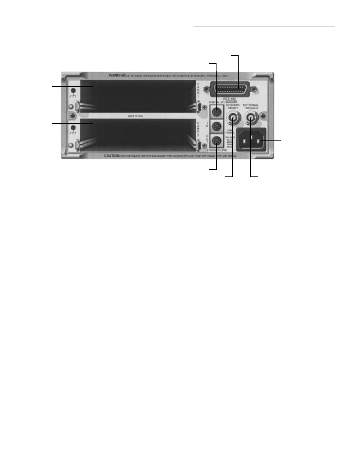
Getting Started
3
4
1
2
8
5
67
1 CARD 1
Slot 1 for switch card. Corresponds
to Card 1 channel status display.
2 CARD 2
Slot 2 for switch card. Corresponds
to Card 2 channel status display.
3 IEEE-488
CONNECTOR
Use standard IEEE-488 cables.
4 DIGITAL I/O
Micro 8-pin DIN connector. Port
consists of four TTL output lines and
one TTL input line (one common line).
Figure 3-2
Model 7001 rear panel
5 TRIGGER LINK IN AND
OUT
Two micro 8-pin DIN connectors.
6 CHANNEL READY
Female BNC connector for TTL output
trigger pulse.
7 EXTERNAL TRIGGER
Female BNC connector for TTL input
trigger pulse.
8 LINE POWER INPUT
WARNING: Connect to grounded outlet
using three-wire power cord.
3-3
Page 28

Getting Started
3.2.3 Channel status display
The channel status display provides real-time status of
each available channel for the two slots. Only the available channels are displayed. There are two channel status display modes; the Channel List entry mode
(SELECT CHANNELS) and the Scan List entry mode
(SCAN CHANNELS). On power-up, the Channel List
entry mode is selected. The SCAN LIST key toggles between the Channel List and the Scan List. The instrument can be returned to the channel status display by
pressing the EXIT key one or more times.
The channel status display is shown in Figure 3-3. This
display is structured as two 10-column grids. The left
grid provides the channel status of the card installed in
slot 1 (CARD 1) and the right grid provides the channel
status of the card installed in slot 2 (CARD 2). As
shown in the illustration, an open channel is represented as a “dot” while a closed channel is represented as a
“dash”.
Channel assignments
mat is automatically determined by the card type.
There is a three-integer format to express matrix card
channels, and a two-integer format to express channels
for all other types of switching cards. The individual
integers that make up the channel assignment are separated by an exclamation point (!).
The channel assignment for-
is Row 1, the second row from the top is Row 2,
the next row is Row 3, and the bottom row is Row
4. The third integer designates the column of the
matrix card. The 10 matrix columns are displayed
by the channel status display. The assignments
for all matrix card channels are presented in Figure 3-4.
If, for example, CARD 1 in Figure 3-3 happened
to be a Model 7012 matrix card, the following
channels would be closed:
Channel 1!2!3 (Slot 1, Row 2, Column 3)
Channel 1!4!9 (Slot 1, Row 4, Column 9)
All other card types: All non-matrix type switch-
ing cards use the two-integer format to express
channel assignments. The first integer, like the
matrix card, designates the slot number. The second integer designates switch card channel number. The channel assignments for these card types
are presented in Figure 3-5.
If, for example, CARD 2 in Figure 3-3 happened
to be a Model 7011 multiplexer card, the following channels would be closed:
Channel 2!14 (Slot 2, Channel 14)
Matrix cards: Matrix cards use the three-integer
format to express channel assignments. The first
integer designates the slot number that the card
is installed in. Thus, a “1” designates slot 1
(CARD 1), and a “2” designates slot 2 (CARD 2).
The second integer designates the row number of
the matrix card. There are four rows; the top row
3-4
Channel 2!36 (Slot 2, Channel 36)
For the Model 7011 multiplexer card, Channel 14
corresponds to Bank 1, Relay 4, and Channel 36
corresponds to Bank 3, Relay 6. See the Model
7011 instruction manual for details.
Page 29
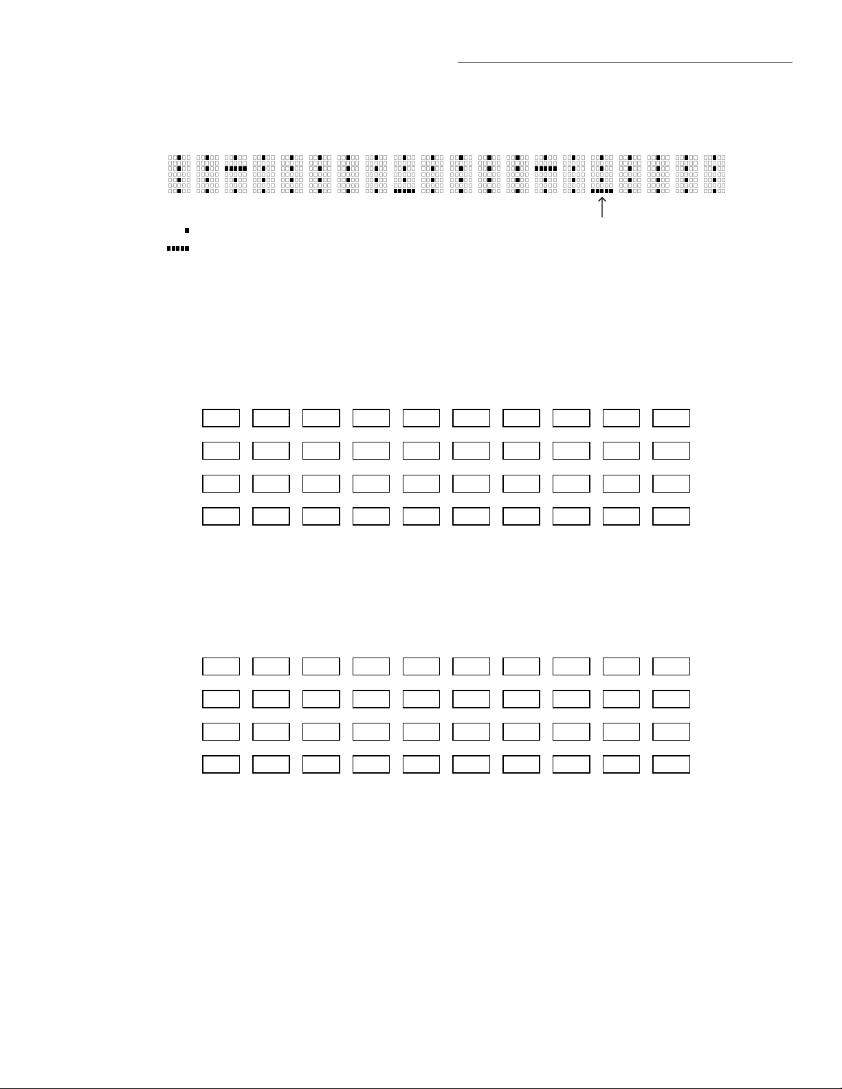
CARD 1 CARD 2
Getting Started
1 23
= Open Channel
= Closed Channel
Figure 3-3
Channel status display
1 2 3 4 5 6 7 8 9 10
1!1!1
1!2!1
1!3!1
1!4!1
REM4TALK
1!1!2
1!2!2
1!3!2
1!4!2
LSTN7SRQ
56
1!1!3
1!2!3
1!3!3
1!4!3
89101234567
Channel 2!36 for Mux
Channel 2!4!6 for Matrix
1!1!4
1!2!4
1!3!4
1!4!4
1!1!5
1!2!5
1!3!5
1!4!5
1!1!6
1!2!6
1!3!6
1!4!6
1!1!7
1!2!7
1!3!7
1!4!7
1!1!8
1!2!8
1!3!8
1!4!8
1!1!9
1!2!9
1!3!9
1!4!9
ARM
8910
1!1!10
1!2!10
1!3!10
1!4!10
A. Slot 1 (Card 1)
1 2 3 4 5 6 7 8 9 10
2!1!1
2!2!1
2!3!1
2!4!1
2!1!2
2!2!2
2!3!2
2!4!2
B. Slot 2 (Card 2)
Exampels : 1!2!4 = Slot 1, Row 2, Column 4
2!3!6 = Slot 2, Row 3, Column 6
Figure 3-4
Channel assignments (matrix cards)
2!1!3
2!2!3
2!3!3
2!4!3
2!1!4
2!2!4
2!3!4
2!4!4
2!1!5
2!2!5
2!3!5
2!4!5
2!1!6
2!2!6
2!3!6
2!4!6
2!1!7
2!2!7
2!3!7
2!4!7
2!1!8
2!2!8
2!3!8
2!4!8
2!1!9
2!2!9
2!3!9
2!4!9
2!1!10
2!2!10
2!3!10
2!4!10
3-5
Page 30

Getting Started
1 2 3 4 5 6 7 8 9 10
1!1
1!2
1!3
1!4
1!5
1!6
1!7
1!8
1!9
1!10
1!11
1!21
1!31
1!12
1!22
1!32
1!13
1!23
1!33
1!14
1!24
1!34
1!15
1!25
1!35
1!16
1!26
1!36
1!17
1!27
1!37
1!18
1!28
1!38
1!19
1!29
1!39
A. Slot 1 (Card 1)
1 2 3 4 5 6 7 8 9 10
2!1
2!11
2!21
2!31
2!2
2!12
2!22
2!32
2!3
2!13
2!23
2!33
2!4
2!14
2!24
2!34
2!5
2!15
2!25
2!35
2!6
2!16
2!26
2!36
2!7
2!17
2!27
2!37
2!8
2!18
2!28
2!38
2!9
2!19
2!29
2!39
B. Slot 2 (Card 2)
1!20
1!30
1!40
2!10
2!20
2!30
2!40
Exampels : 1!18 = Slot 1, Channel 18
2!36 = Slot 2, Channel 36
Figure 3-5
Channel assignments (non-matrix type cards)
3-6
Page 31

Getting Started
3.3 Operation demo
A fast and easy way to acquaint yourself with basic
front panel operation is to use the following operation
demo. This demo uses the built-in 40-channel multiplexer simulator. This will allow you to simulate operation without the need of a switching card.
3.3.1 Initial configuration
WARNING
Before turning the Model 7001 on,
make sure it is connected to a
grounded power receptacle using the
supplied power cord or the equivalent. Failure to properly ground the
unit creates a shock hazard that could
result in injury or death.
Step 1 of the following procedure will RESET the Model 7001 to a default scan configuration that is required
for the demonstration procedures (paragraphs 3.3.2
and 3.3.3). Step 2 will assign the 40-channel multiplexer simulator to slot 2.
1. Press the CARD CONFIGURATION key. The
CARD CONFIG MENU will be displayed.
2. Place the cursor on TYPE and press ENTER. The
SET CARD TYPE menu will be displayed.
3. Place the cursor on SLOT-2 and press ENTER. The
“SLOT-2 CARD: XXXX” message will be displayed
(where XXXX is the current card assignment for
slot 2).
4. Use the cursor keys to display model number
“9990”.
5. With “SLOT-2 CARD: 9990” displayed, press ENTER. The SET CARD TYPE menu will be displayed.
6. Press EXIT twice to exit from the CARD CONFIG
MENU.
3.3.2 Close and open channels
The following procedures assume that the initial configuration procedure in paragraph 3.3.1 has been performed. This initialization will assign the 40-channel
multiplexer simulator to Slot 2 for the following operating examples.
Step 1. RESET instrument
1. Press the MENU key. The MAIN MENU will be
displayed.
2. Place the cursor on SAVESETUP using the and
cursor keys, and press the ENTER key. The
SETUP MENU will be displayed.
3. Place the cursor on RESET and press ENTER. The
“RESETTING INSTRUMENT” message will be
displayed.
4. Press ENTER again. The “RESET COMPLETE”
message will be displayed.
5. Press ENTER to return the display to the SETUP
MENU.
6. Press EXIT twice to exit from the MAIN MENU.
Step 2. select multiplexer simulator
NOTE
The simulator cannot be selected if
there is a Model 701X series card installed in slot 2.
NOTE
The Model 7001 must be in the Channel List display mode (“SELECT
CHANNELS” prompt displayed). The
SCAN LIST key toggles the channel
status display between “SELECT
CHANNELS” (Channel List) and
“SCAN CHANNELS” (Scan List). If
the instrument is not in the channel
status display mode, press EXIT until
it is.
Create Channel List:
The Channel List specifies which channels you wish to
close and open. The Channel List can be made up of a
single channel, or multiple channels. Consecutive
channels can be specified as a range.
The following procedure will create a Channel List that
includes Channels 1, 2, and 6 through 9:
3-7
Page 32

Getting Started
1. If the Channel List is not currently empty, press
CLEAR LIST. The following message indicates an
empty Channel List:
SELECT CHANNELS
2. Individual Channel Entry - Perform the following
steps to enter Channels 1 and 2 in the Channel List:
A. Press “2” and then “1” to enter Channel 1 into
the Channel List. The “2” selects slot 2.
SELECT CHANNELS 2!1
B. Press or ENTER to enter the channel sepa-
rator (,).
SELECT CHANNELS 2!1,
C. Press “2” and then “2” to enter channel 2, and
then press or ENTER to enter the channel
separator (,).
SELECT CHANNELS 2!1, 2!2,
3.3.3 Scan channels
The following procedures assume that the initial configuration procedure in paragraph 3.3.1 has been performed. This initialization will assign the 40-channel
multiplexer simulator to Slot 2 for the following scan
examples.
NOTE
The Model 7001 must be in the Scan
List display mode (“SCAN CHANNELS” prompt displayed). The SCAN
LIST key toggles the channel status
display between “SELECT CHANNELS” (Channel List) and “SCAN
CHANNELS” (Scan List). If the instrument is not in the channel status display mode, press EXIT until it is.
Create scan list
Perform the following steps to create a scan list that
will scan channels 1 through 20:
3. Range Entry - Perform the following steps to enter
Channels 6 through 9 as a range:
A. Press “2” and then “6” to enter the range limit
(Channel 6).
SELECT CHANNELS 2!1, 2!2, 2!6
B. Press “-” to enter the range separator. Note that
the slot number for the next channel is automatically entered.
SELECT CHANNELS 2!1, 2!2, 2!6-2!
C. Press “9” to enter the range limit.
SELECT CHANNELS 2!1, 2!2, 2!6-2!9
Close and open channels
1. Press CLOSE to close the channels specified in the
Channel List.
2. Press OPEN to open the channels specified in the
Channel List. Note that OPEN ALL opens all channels (even those not specified in the Channel List).
1. If the Scan List is not currently empty, press
CLEAR LIST. The following message indicates an
empty Scan List:
SCAN CHANNELS
2. Press “2” and then “1” to enter the slot and the
range limit.
SCAN CHANNELS 2!1
3. Press “-” to enter the separator for the range limits.
Notice that the slot number for the next channel
will automatically be entered.
SCAN CHANNELS 2!1-2!
4. Press “2” and then “0” to enter the limit of the
range.
SCAN CHANNELS 2!1-2!20
5. Press or ENTER to enter the scan list terminator
(,).
SCAN CHANNELS 2!1-2!20,
3-8
Page 33

Getting Started
Note: Instead of specifying the 20 channels in the scan
list as a range, they could have been entered individu-
ally (2!1, 2!2, 2!3, .... 2!20,).
Manual scan
The RESET defaults configure the instrument to manually scan an infinite number of channels. After the 20th
channel is scanned, operation will wrap around to the
beginning of the scan list (Channel 1).
1. Press STEP to take the Model 7001 out of the idle
state. The ARM indicator will turn on.
2. Press the STEP key to scan the first channel. This
channel will remain closed until another channel is
scanned.
3. Press the STEP key to scan the second channel. The
first channel will open and the second channel will
close.
4. Each press of the STEP key will open the previous
channel and close the next channel (break-beforemake).
5. When finished, press OPEN ALL to abort the scan
and open all channels. The instrument goes into
the idle state (ARM indicator turns off).
4. Place the cursor on CHANNEL-SPACING and
press ENTER. The SELECT CHAN SPACING
menu will be displayed.
SELECT CHAN SPACING
TRIGLINK IMMEDIATE HOLD
5. Place the cursor on IMMEDIATE and press ENTER. The display will return to the CHANNEL
CONTROL menu.
6. Press EXIT twice to exit from the CONFIGURE
SCAN menu and return to the channel status display.
7. Press CARD CONFIGURATION. The CARD
CONFIG MENU will be displayed.
CARD CONFIG MENU
DELAY READ-I/O-CARD
8. Place the cursor on DELAY and press ENTER. The
SET DELAY FOR: menu will be displayed.
9. Place the cursor on SLOT-2 and press ENTER. The
delay period (in seconds) will be displayed.
(2)DELAY = 00000.000
Automatic scan
Perform the following steps to automate the 20-channel scan. A 0.5 second delay will be used between each
channel.
1. Press OPEN ALL if there are any channels closed
or the ARM indicator is on
2. Press the SCAN CONFIGURATION key. The
CONFIGURE SCAN menu will be displayed.
NOTE
Due to space limitations, not all menu
selections can be displayed on the
Model 7001 at the same time. A displayed arrow ( or ) indicates
that there are additional menu selections to choose from. Use the and
cursor keys to display them.
3. Using the and keys, place the cursor on
CHAN-CONTROL and press ENTER. The CHANNEL CONTROL menu will be displayed.
10. Use the keypad to set the delay for 0.5 seconds.
(2)DELAY = 00000.500
This delay will occur after each channel closes.
11. Press ENTER. The display will return to the SET
DELAY FOR: menu.
12. Press EXIT twice to return to the channel status
display.
13. To start the scan, simply press STEP. The instrument leaves the idle state (ARM indicator on) and
immediately closes the first channel. After a 0.5
second delay the first channel will open and the
second channel will close. This automatic scan will
continue at the 0.5 second scan rate.
14. When finished, press OPEN ALL.
TIMER controlled scans
An internal timer can be used to control the time interval between the scans. The 20-channel scan will be
modified by using a TIMER to place a 20-second interval between the start of each scan.
3-9
Page 34

Getting Started
1. Press OPEN ALL to ensure that the instrument is in
the idle state.
2. Press SCAN CONFIGURATION. The CONFIGURE SCAN menu will be displayed.
3. Place the cursor on SCAN-CONTROL and press
ENTER. The SCAN CONTROL menu will be displayed.
4. Place the cursor on SCAN-SPACING and press
ENTER. The SELECT SCAN SPACING menu will
be displayed.
SELECT SCAN SPACING
TIMER EXTERNAL GPIB MANUAL
5. Place the cursor on TIMER and press ENTER. The
timer interval (in seconds) will be displayed.
INTERVAL = 00000.001
6. Use the keypad to key in an interval of 20 seconds.
INTERVAL = 00020.000
Arm
Layer
Scan
Layer
Channel
Layer
Idle
Arm
Event
Scan
Event
Channel
Event
Yes
Yes
Yes
Scan
Channel
No
Another
Arm
?
No
Another
Scan
?
No
Another
Channel
?
Arm
Count
Number of
Scans
Number of
Channels
7. Press ENTER. The display will return to the SCAN
CONTROL menu.
8. Press EXIT twice to exit from the CONFIGURE
SCAN menu and return to the channel status display.
9. To start the scan, press STEP. The first scan will
start immediately and stop after the 20th channel
closes. After 10 additional seconds expires (20 seconds after the start of the scan), the next scan will
start.
10. When finished, press OPEN ALL.
3.4 Overview of scan process
The following overview is intended to acquaint you
with the basic scan fundamentals without overwhelming you with the details of enhanced capabilities. This
brief overview is sufficient to support the operation examples in paragraphs 3.5 (front panel) and 3.6 (IEEE488 bus). For a complete explanation on all aspects of
the scan process, see paragraph 4.5.4.
The simplified model for scan operation is shown in
Figure 3-6. As shown, scan operation consists of three
layers; the arm layer, scan layer and channel layer.
Figure 3-6
Simplified model of scan operation
Idle
The instrument is considered to be in the idle state
whenever it is not operating within one of the layers of
the model. The front panel ARM indicator is off when
the instrument is in the idle state.
When the Model 7001 is taken out of the idle state by
pressing STEP (or sending the :INIT or :INIT:CONT
ON command over the IEEE-488 bus), the ARM indicator turns on and operation proceeds into the arm layer.
Arm layer
In general, the instrument requires an arm event to allow operation to proceed to the scan layer. With Immediate arm spacing selected, operation immediately
proceeds to the next layer when the instrument is taken
out of the idle state. With one of the other arm spacing
events selected, the instrument will wait until the appropriate event occurs.
3-10
Page 35

Getting Started
With Manual arm spacing selected, the instrument will
wait until the front panel STEP key is pressed. With
GPIB arm spacing selected, the instrument will wait
until a bus trigger (GET or *TRG) is received. With External arm spacing selected, the instrument will wait
until an input trigger (via EXTERNAL TRIGGER connector on rear panel) is received. With Trigger Link arm
spacing selected, the instrument will wait until an input trigger is received (via TRIGGER LINK).
After all other scanning operations are completed, the
instrument can be returned to the arm layer by
programming the instrument for additional arms. The
arm count can be set to a finite value (1 to 9999) or to
infinity.
After the instrument leaves the arm layer, operation
proceeds into the scan layer.
Scan layer
In general, the instrument requires a scan event to allow operation to proceed to the channel layer. With Immediate scan spacing selected, operation immediately
proceeds to the next layer. With one of the trigger scan
spacing events selected (Timer, External, GPIB, Manual, Trigger Link), the instrument will wait until the appropriate event occurs. With Timer scan spacing
selected, the first pass through the scan layer will occur
immediately. If programmed for additional scans, the
instrument will wait until the Timer times out. The
Timer can be set for an interval from 1msec to
99999.999 seconds.
nel. With Timer channel spacing selected, the first
channel will be scanned immediately. Each additional
channel will wait for the Timer to time out before it will
be scanned.
Typically, the channel count (number of channels to
scan) is set to the number of channels that are contained in the Scan List (scan-list-length). However, the
channel count can be set to a finite value (1 to 9999) or
to infinity.
3.5 Initial configuration
WARNING
Before turning the Model 7001 on,
make sure it is connected to a
grounded power receptacle using the
supplied power cord or the equivalent. Failure to properly ground the
unit creates a shock hazard that could
result in injury or death.
Before performing any basic operations (close/open
channels or scan channels) there are a few initial configurations that must first be considered. If you are using Model 701X series cards (i.e. Model 7011, 7012 and
7013), and they are already installed in the mainframe
(as explained in Section 2), skip the following configuration information and proceed to paragraphs 3.5
(front panel operation) and 3.6 (IEEE-488 bus operation).
The scan count (number of scans) can be set to a finite
value (1 to 9999) or for an infinite number of scans.
After the instrument leaves the scan layer, operation
proceeds into the channel layer.
Channel layer
In general, channel events control the channel scan
rate. With Immediate channel spacing selected, a channel will be scanned immediately. With one of the other
channel spacing events selected (Timer, External, GPIB,
Manual or Trigger Link), the instrument will wait until
the appropriate event occurs before scanning a chan-
3.5.1 Switching card simulators
Instrument operation can be performed without any
switching cards installed in the Model 7001 by using
the switching card simulators. By selecting the appropriate switching card simulator, the Model 7001 will
operate as if a 40-channel switching card or a 4
trix card were installed. This is useful if you want to develop a test program without having a card installed.
When a slot is assigned the model number 9990, the
mainframe will operate as if a 40-channel switching
card is installed. When a slot is assigned model number
9991, the mainframe will operate as if a 4
×
10 ma-
×
10 matrix
3-11
Page 36

Getting Started
card is installed. These simulator model numbers are
assigned by setting card TYPE in the CARD CONFIG
MENU (see paragraph 3.5.3). If you are going to use the
simulators to perform the operating examples in paragraph 3.6, configure Slot 1 for non-matrix switching
(model 9990), and Slot 2 for matrix switching (model
9991).
NOTE
A simulator cannot be assigned to a
slot that already has a Model 701X series card installed in it. To use a simulator, turn off the Model 7001 and
remove the card from the slot.
3.5.2 Installing switching cards
The procedure to install switching cards in the mainframe is explained in Section 2 of this manual. If using
switching card simulators as explained in the previous
paragraph, leave the slots empty.
Perform the following procedure to assign a model
number (or designate it as empty) to one or both of the
mainframe slots:
1. Turn on the Model 7001. During the power-up sequence, the instrument will briefly display which
Model 701X series cards are currently installed, or
the last slot assignments.
Example
1, and slot 2 was last designated to be empty, the
following message will be displayed briefly during
the power-up sequence:
If slot 2 is empty and you do not wish to assign it a
simulator, stop here and proceed to basic front
panel operation (paragraph 3.5). If slot 2 has a non701X series card (i.e. Model 7156) installed in it,
continue with this procedure to assign the appropriate model number to the slot.
2. Press CARD CONFIGURATION to enable the following menu:
If a Model 7013 card is installed in slot
#1 = 7013 #2 = NONE
3.5.3 Card type
In order for the Model 7001 to operate properly, it must
know what type of card is installed in each of its two
slots. If a Model 701X series card (such as the Model
7011, 7012 or 7013) is installed in a slot, the mainframe
automatically identifies the card type on power-up and
configures its operation appropriately. With Model
701X series cards installed in the mainframe, you can
disregard the procedure in this paragraph and proceed
on to basic front panel operation (paragraph 3.5).
For other card types (non-701X series cards) and simulators, the user must assign the proper model number
to the slot. Once a model number is assigned by the user, it will be remembered on subsequent power-ups as
long as a Model 701X series card is not installed. Note
that a slot can also be designated as empty. With this assignment, the front panel status display for that slot
will be disabled.
A slot assignment change could make a channel that is
currently included in the Scan List and/or a Channel
Pattern unavailable. The unavailable channel causes
the Scan List and/or the affected Channel Pattern to
clear (see paragraphs 4.5.2 and 4.5.5 for details).
CARD CONFIG MENU
TYPE #-OF-POLES CARD-PAIR
DELAY READ-I/O-CARD
NOTE
A displayed arrow ( or ) indicates that more menu selections are
available. Use the cursor keys ( and
) to display them.
3. Using the and cursor keys, place the cursor
(flashing menu item) on TYPE and press ENTER.
The following menu will be displayed:
SET CARD TYPE
SLOT-1 SLOT-2
4. Place the cursor on the slot that needs to be assigned and press ENTER. For example, if you selected Slot 1, the following typical message will be
displayed:
SLOT-1 CARD: NONE
The above message indicates that there is not a
Model 701X series card installed in slot 1, and slot
1 was last designated as an empty slot.
3-12
Page 37

Getting Started
5. Perform one of the following steps:
A. Empty Slot
empty, use the cursor keys ( and ) to display the “NONE” message. Example:
SLOT-1 CARD: NONE
The above message indicates that, when ENTERed (Step 6), slot 1 will be configured to operate as an empty slot.
B. Simulator
40- channel switching card, use the cursor keys
( and ) to display model number 9990. If
you want the slot to simulate a 4
card, use the cursor keys to display model
number 9991. Example:
SLOT-1 CARD: 9990
The above message indicates that, when ENTERed (Step 6), slot 1 will be configured to operate as a 40-channel switching card.
C. Non-701X Series Card
the non-701X series card, use the cursor keys
( and ) to display the model number of
that card. For example, if a Model 7156 is installed in slot 1, use the cursor keys to display
the following message:
SLOT-1 CARD: 7156
If you want to assign the slot as
If you want the slot to simulate a
To assign the slot to
×
10 matrix
3.6 Front panel operation
Basic front panel operation will be demonstrated
through the use of examples. One example demonstrates close/open operation and the other example
demonstrates scanning. These examples are only intended to teach basic operation. Complete details for
using the full capabilities of the Model 7001 from the
front panel are contained in Section 4 of this manual.
NOTE
Operation examples assume that the
Model 7001 is initially configured for
proper operation as explained in paragraph 3.5.
3.6.1 Close/open operation example
One of the basic functions of the Model 7001 is to simply close and open one or more specified channels. The
following example will demonstrate this operation.
The example can be performed if you have a non-matrix switching card installed and/or a matrix card installed. If using the card simulators, configure slot 1 for
non-matrix switching (model 9990) and slot 2 for matrix switching (model 9991) as explained in paragraph
3.5.3.
The above message indicates that, when ENTERed (Step 6), slot 1 will operate properly
with a Model 7156 installed in it.
6. With the appropriate slot assignment message displayed, press ENTER to execute the assignment.
The display will return to the SET CARD TYPE
menu.
7. To assign the other slot, repeat steps 4 through 6.
8. To exit from the CARD CONFIG MENU, press
EXIT twice.
NOTE
The EXIT key can be used anywhere in
the CARD CONFIG MENU structure.
Each press of the EXIT key will back
up the display to the previous menu
level without executing a pending operation.
Channels that are controlled in this example include:
Switching Card Channels: 1, 3, 4, 5 and 6.
Matrix Card Channels: Row 1 Column 1, Row 2 Column 2, Row 2 Column 3, Row 2 Column 4, Row 2 Column 5 and Row 2 Column 6
Perform the following steps to close/open channels of
a non-matrix switching card and/or a matrix card.
Step 1. Place instrument in Channel List display state.
If not already in the channel status display state, press
EXIT one or more times. Once in the channel status display state, the SCAN KEY will toggle between the
Channel List (SELECT CHANNELS) and the Scan List
(SCAN CHANNELS).
3-13
Page 38

Getting Started
SELECT CHANNELS
If there is Channel List currently displayed, press
CLEAR LIST to cancel it. Also, if there are any channels
currently closed, press OPEN ALL to open them.
Step 2. Enter Channel List.
Switching Card For a non-matrix switching card,
enter the Channel List (Channels 1, 3, 4, 5 and 6) for slot
1 as follows:
NOTE
The following procedure assumes that
slot 1 is configured for non-matrix
switching. If using slot 2 for non-matrix switching, modify (A) of steps 1
and 2 by pressing “2” instead of “1”.
1. Enter first channel (Channel 1) using the single
channel entry method:
A. Press “1” Enters slot
B. Press “1” Enters channel
C. Press “ ” or “ENTER” Enters channel sepa-
rator (comma)
Note: The following procedure assumes that Slot 2 is
configured for a matrix. If using slot 1 for a matrix,
modify (A) of steps 1 and 2 by pressing “1” instead of
“2” to enter the slot.
1. Enter first channel (Row 1 Column 1) using the single channel entry method:
A. Press “2” Enters slot
B. Press “1” Enters row
C. Press “1” Enters column
D. Press “ ” or “ENTER” Enters channel sepa-
rator (comma)
SELECT CHANNELS 2!1!1,
2. Enter the rest of the channels (Row 2 Column 2
through Row 2 Column 5) using the channel range
entry method:
A. Press “2” Enters slot
B. Press “2” Enters row of first channel
C. Press “2” Enters column of first chan-
nel
D. Press “-” Enters range designator
E. Press “2” Enters row of last channel
F. Press “5” Enters column of last channel
G. Press “ ” or Enters channel list terminator
“ENTER” (comma)
SELECT CHANNELS 1!1,
2. Enter the rest of the channels (Channels 3 through
6) using the channel range entry method:
A. Press “1” Enters slot
B. Press “3” Enters first channel
C. Press “-” Enters range designator
and slot
D. Press “6” Enters last channel
E. Press “ ” or Enters channel list termi-
“ENTER” nator (comma)
SELECT CHANNELS 1!1, 1!3-1!6,
Note: Channels 3, 4, 5, and 6 could have been entered
using the single channel entry method demonstrated
in step 1.
Matrix card For a matrix card, enter the Channel List
(Row 1 Column 1,Row 2 Column 2, Row 2 Column 3,
Row 2 Column 4, and Row 2 Column 5 for slot 2) as follows:
SELECT CHANNELS 2!1!1, 2!2!2-2!2!5,
Note: The single channel entry method demonstrated
in step 1 could have been used to enter the channels for
row 2.
Step 3. Close (or open) listed channels.
1. To close the channels specified in the channel list,
simply press CLOSE. The closed channels will be
indicated on the channel status display.
2. To open the closed channels that are specified in
the channel list, press OPEN. Note that only channels specified in the list are opened. Unspecified
channels (as well as channels in the channel list)
are opened by pressing OPEN ALL.
Closing additional channels
After you have closed the channels in channel list, you
may want to close one or more additional channels.
Closing an additional channel is simply a matter of en-
3-14
Page 39

Getting Started
tering the channel in the channel list and pressing
“CLOSE”. For example, assume your channel list looks
like this:
SELECT CHANNELS 1!1, 1!3-1!6,
To close channel 1!8, position the cursor at the end of
the channel list and press “1”, “8” and then CLOSE.
The channel list will now look like this:
SELECT CHANNELS 1!1, 1!3-1!6, 1!8,
You could also have closed the additional channel by
first clearing the channel list (pressing CLEAR LIST),
and then entering and closing the channel. However,
keep in mind that once you clear a channel list, it cannot be recalled. You will have to re-enter the entire list.
Opening closed channels
As previously explained, pressing OPEN will open all
the channels specified in the channel list. If you want to
open one or more, but not all channels, you will have
to clear the channel list by pressing CLEAR LIST, and
then enter a new channel list that specifies the closed
channels you wish to open. Once the new channel list
is entered, simply press OPEN to open those channels.
Perform the following steps to scan channels of a nonmatrix switching card and/or a matrix card. Three
scans of the specified Scan List will be performed.
Step 1. RESET the Model 7001.
By performing RESET, the Model 7001 will set itself to
default conditions that are typically used to control a
scan.
1. Press the MENU key. The following menu will be
displayed:
MAIN MENU
SAVESETUP GPIB DIGITAL-I/O
TEST LANGUAGE GENERAL
2. Use the cursor keys ( and ) to place the cursor
(flashing menu item) on SAVESETUP and press
the ENTER key. The following menu will be displayed:
SETUP MENU
SAVE RESTORE PWRON RESET
3. Place the cursor on RESET and press ENTER. The
following message will be displayed;
3.6.2 Scan operation example
The Model 7001 can scan through a list of specified
channels. The order of the channels in the Scan List determines the channel order for the scan. The following
example will demonstrate this operation.
The example can be performed if you have a non-matrix switching card installed and/or a matrix card installed. If using the card simulators, configure slot 1 for
non-matrix switching (model 9990), and slot 2 for matrix switching (model 9991) as explained in paragraph
3.4.3.
Channels that are scanned in this example include:
Switching Card Channels: 1, 3, 4, 5, and 6.
Matrix Card Channels: Row 1 Column 1, Row 2 Column 2, Row 2 Column 3, Row 2 Column 4, Row 2 Column 5 and Row 2 Column 6.
RESETTING INSTRUMENT
4. Press ENTER. The following message will be displayed:
RESET COMPLETE
5. Again press ENTER to return to the SETUP
MENU.
6. Press EXIT twice to exit from the menu structure.
Step 2. Place instrument in Scan List display state.
With the instrument in the Channel List display state,
press SCAN LIST to select the Scan List entry display
state. The following message prompt will be displayed:
SCAN CHANNELS
If there is a scan list currently displayed, press CLEAR
LIST to cancel it. Also, if there are any channels currently closed, press OPEN ALL to open them.
3-15
Page 40

Getting Started
Step 3. Enter Scan List.
Switching Card For a non-matrix switching card,
enter the scan list (Channels 1, 3, 4, 5, and 6) for slot 1
as follows:
Note: The following procedure assumes that slot 1 is
configured for non-matrix switching. If using slot 2 for
non-matrix switching, modify (A) of steps 1 and 2 by
pressing “2” instead of “1”.
1. Enter first channel (Channel 1) using the single
channel entry method:
A. Press “1” Enters slot
B. Press “1” Enters channel
C. Press “ ” or “ENTER” Enters channel sepa-
rator (comma)
SCAN CHANNELS 1!1,
2. Enter the rest of the channels (Channels 3 through
6) using the channel range entry method:
A. Press “1” Enters slot
B. Press “3” Enters first channel
C. Press “-” Enters range designator and
slot
D. Press “6” Enters last channel
E. Press “ ” or Enters channel list terminator
“ENTER” (comma)
SCAN CHANNELS 1!1, 1!3-1!6,
Note: Channels 3, 4, 5 and 6 could have been entered
using the single channel entry method demonstrated
in step 1.
Matrix Card For a matrix card, enter the scan list
(Row 1 Column 1, Row 2 Column 2, Row 2 Column 3,
Row 2 Column 4, and Row 2 Column 5 for slot 2) as follows:
Note: The following procedure assumes that slot 2 is
configured for a matrix. If using slot 1 for a matrix,
modify (A) of steps 1 and 2 by pressing “1” instead of
“2”.
1. Enter first channel (Row 1 Column 1) using the single channel entry method:
A. Press “2” Enters slot
B. Press “1” Enters row
C. Press “1” Enters column
D. Press “ ” or Enters channel separa-
“ENTER” tor (comma)
SCAN CHANNELS 2!1!1,
2. Enter the rest of the channels (Row 2 Column 2
through Row 2 Column 5)using the channel range
entry method:
A. Press “2” Enters slot
B. Press “2” Enters row of first channel
C. Press “2” Enters column of first chan-
nel
D. Press “-” Enters range designator and
slot
E. Press “2” Enters row of last channel
F. Press “5” Enters column of last channel
G. Press “ ” or Enters channel list terminator
“ENTER” (comma)
SCAN CHANNELS 2!1!1, 2!2!2-2!2!5,
Note: The single channel entry method demonstrated
in step 1 could have been used to enter the channels for
row 2.
Step 4. Configure channel layer of scan.
NOTE
When RESET was performed (Step 1),
the channel layer was reset to MANUAL channel scanning. In MANUAL,
the first press of STEP will take the instrument out of the idle state and each
subsequent press will manually step
through the scan. Go ahead and try it.
When finished, press OPEN ALL to
place the Model 7001 in the idle state.
For this example, the channel scan rate will be controlled by the timer. In general, every time the timer
times out, the next channel in the scan will be selected.
Since the Model 7001 was RESET, only CHANNEL
SPACING needs to be programmed.
Configure the channel layer as follows:
3-16
Page 41

Getting Started
1. Press SCAN CONFIGURATION to display the following menu:
CONFIGURE SCAN
CHAN-CONTROL SCAN-CONTROL
ARM-CONTROL CHAN-RESTRICTIONS
2. Using the cursor keys ( and ), place the cursor on CHAN-CONTROL (Channel Layer) and
press ENTER. The following menu will be displayed:
CHANNEL CONTROL
CHANNEL-SPACING NUMBER-OF-CHANS
CONTROL
3. Place the cursor on CHAN-SPACING and press
ENTER. The following menu will be displayed:
SELECT CHAN SPACING
TIMER EXTERNAL GPIB MANUAL
TRIGLINK IMMEDIATE HOLD
4. Place the cursor on TIMER and press ENTER. The
current timer interval (in seconds) will be displayed:
Step 5. Configure scan layer of scan.
When the Model 7001 was RESET (Step 1), the scan layer was reset to IMMEDIATE scan spacing, which is appropriate for this example. This means each
programmed scan will occur immediately and not wait
for an event to occur.
Also, the scan layer was RESET to perform an infinite
number of scans. Since this example requires only three
scans, change the NUMBER OF SCANS as follows:
1. The Model 7001 should be displaying the following menu:
CONFIGURE SCAN
CHAN-CONTROL SCAN-CONTROL
ARM-CONTROL CHAN-RESTRICTIONS
2. Place the cursor on SCAN-CONTROL and press
ENTER. The following menu will be displayed:
SCAN CONTROL
SCAN-SPACING NUMBER-OF-SCANS
CONTROL
INTERVAL = 00000.001
The above message indicates that the timer is currently set for 1msec.
5. Set the timer for a half second interval by using the
cursor keys and number keys. The timer interval
should look like this:
INTERVAL = 00000.500
6. Press ENTER to select the timer as the event that
controls the channel scan. The display returns to
the following menu:
CHANNEL CONTROL
CHANNEL-SPACING NUMBER-OF-CHANS
CONTROL
Note: When the Model 7001 was RESET, the number of channels to scan was set to the scan list
length, which is what you want for this example.
7. Press EXIT to return the display to the CONFIGURE SCAN menu.
3. Place the cursor on NUMBER-OF-SCANS and
press ENTER. The following menu will be displayed:
NUMBER OF SCANS
INFINITE ENTER-SCAN-COUNT
4. Place the cursor on ENTER-SCAN-COUNT and
press ENTER. The following typical message indicating the scan count will be displayed:
SCAN COUNT = 0000
A scan count of zero indicates that the scan layer is
currently configured for an infinite number of
scans.
5. Key in a scan count of 3.
SCAN COUNT = 0003
6. To configure the instrument for three scans, press
ENTER. The display will return to the SCAN
CONTROL menu.
7. Press EXIT twice to exit from the menu structure.
3-17
Page 42

Getting Started
Note: RESET (Step 1) configured the arm layer for IMMEDIATE arming, and for an arm count of one. Both of
these arm conditions are appropriate for this example.
Thus, arm layer configuration is not necessary.
Step 6. Perform the scan.
To perform the scan, simply press the STEP key. On the
display, the scan will arm (ARM indicator will turn on),
and the mainframe will scan through the channels of
the scan list three times. At the conclusion of the third
scan, the Model 7001 will return to the idle state (ARM
indicator will turn off). Note however that the last
channel in the scan list remains closed.
NOTE
The last channel in the scan remains
closed. If your test requires that the
last channel open after the scan, proceed to the next step.
Step 7. Open the last channel
To have the last channel open at the conclusion of the
third scan, you will need to assign a blank channel pattern (all channels open) from memory as the last channel entry in the Scan List.
2. Use the cursor key to position the cursor at the
end of the scan list.
3. Enter the blank channel pattern by pressing “M”,
“1” and then or ENTER to terminate the Scan
List.
SCAN CHANNELS 1!1, 1!3-1!6, 2!1!1, 2!2!2-2!2!5, M1,
Repeat the scans by again pressing STEP. At the conclusion of the third scan, the last channel (Channel 2!2!5, if
using the scan list above), will open.
3.7 IEEE-488.2 and SCPI basics
The following paragraphs discuss fundamental information concerning operation over the IEEE-488 bus.
Detailed information on operating the instrument from
over the bus is contained in Section 5 of this manual.
SCPI overview
IEEE-488.2 defines a syntax for sending data to and
from instruments. It also defines a set of Common
Commands that are used to perform basic operations
such as reading status registers, providing triggers and
resetting the instrument to default conditions.
To save a blank channel pattern in memory, perform
the following steps:
1. Display the Channel List (SELECT CHANNELS)
and press OPEN ALL to open all channels.
2. Press STORE. The following typical message will
be displayed:
STORE CHANS AT #001
3. To store the blank channel pattern in memory location 1, press ENTER. Note that the blank channel
pattern could have been stored at any one of the
100 memory locations (1 to 100) by keying in the
desired value and then pressing ENTER.
With a blank channel pattern stored at memory location 1 (M1), add it to your Scan List as follows:
1. Display the scan list (press SCAN LIST if necessary).
SCPI (Standard Commands for Programmable Instruments) defines a standard set of commands (and format) to control every other aspect of instrument
operation. Together, IEEE-488.2 and SCPI create a command structure for all programmable instruments.
Compatibility
An instrument that uses the IEEE-488.2 standard and
SCPI does not have any special hardware requirements. The IEEE-488 interface that you used with the
old standard will work with the new standard. Simply
connect the Model 7001 to a computer that is equipped
with an IEEE-488 interface.
NOTE
The term GPIB (General Purpose Interface Bus) is used in this manual and
in the menu structure of the instrument. GPIB is simply another term for
the IEEE-488 bus.
3-18
Page 43

Getting Started
3.7.1 Bus connections
Before using the instrument over the bus, you must
connect the IEEE-488 connector on the rear panel of the
instrument to the IEEE-488 connector of your controller. Use a Keithley Model 7007 or similar IEEE-488 cable for this connection.
3.7.2 Primary address
The primary address of the Model 7001 must agree
with the primary address you intend to specify in the
controller’s programming language. The factory setting for the primary address is 7, so if you intend to use
that address, you need not change it. However, the primary address can be set to any value between 0 and 30
by using the GPIB setup menu (ADDRESS selection)
available with the MENU key.
3.7.3 Abbreviated common command summary
Table 3-1 provides an abbreviated list of Common
Commands which are defined by the IEEE-488.2 standard. These are the Common Commands that are most
used for bus operation. Note that each Common Command is preceded by a star (*).
3.7.4 Abbreviated SCPI command summary
Most instrument operations are controlled using SCPI
commands. Table 3-2 provides an abbreviated list of
the SCPI commands necessary to perform some basic
operations.
Not shown in the table are companion query commands for the :ARM and :TRIGger Subsystem commands (:COUNt?, :DELay?, :SOURce?, and :TIMer?).
For example, the :TRIGger:SOURce? query command
is used to request the currently selected control source.
After the query command is sent and the Model 7001 is
addressed to talk, a message identifying the selected
control source will be sent to the computer.
Table 3-1
Abbreviated common command summary
Mnemonic Name Description
*CLS Clear status Clears Error Queue and event registers.
*RST Reset Returns the 7001 to *RST default conditions (see Table 5-6).
*TRG Trigger Issues a bus trigger (same as group execute trigger command; GET).
*SAV <n> Save Saves the current setup configuration in memory (n = 0 to 9).
*RCL <n> Recall Returns the instrument to the setup configuration stored in memory
(n = 0 to 9).
3-19
Page 44

Getting Started
Table 3-2
Abbreviated SCPI command summary
:SYSTem
:PRESet
[:ROUTe]
:CLOSe <list>
:STATe ?
:OPEN <list>|ALL
:SCAN <list>
:INITiate
:ABORt
:ARM
:LAYer2
:COUNt <n>|INF
:DELay <num>
:SOURce HOLD|IMMediate|
TIMer|MANual|BUS|TLINk|
EXTernal
:TIMer <num>
:TRIGger
:COUNt <n>|INF
:AUTo ON/OFF
:DELay <num>
:SOURce HOLD|IMMediate|MANual|
BUS|TLINk|EXTernal|TIMer
:TIMer <num>
Subsystem command path.
Set scan to a default configuration (see Table 5-6)
Subsystem command path.
Path and command to close specified channels:
Request channels that are closed.
Open specified (or all) channels.
Path and command to specify channel list:
Initiate one trigger (scan) cycle.
Reset trigger system and goes to idle state.
Subsystem command path to configure scan:
Path to program scan layer:
Program number of scans (1 to 9999, or INFinite).
Program delay (0 to 99999.999 seconds
Select event to control scan spacing.
Set timer interval (0.001 to 99999.999 sec).
Subsystem command path to program channel layer:
Program number of channels (1 to 9999, or INFinite).
Enable/disable automatic scan list count.
Program delay (0 to 99999.999 sec)
Select event to control channel spacing.
Set timer interval (0.001 to 99999.999 sec).
Note: Command shortform is indicated by the uppercase characters. For example, instead of sending “:arm:layer2:source immediate”,
you can send “:arm:lay2:sour imm”.
3.7.5 Syntax rules
The root command for the above example is :ROUTe.
This is an optional command word (as indicated by the
brackets in the table) and need not be used.
The following information explains some of the programming syntax for the Model 7001. For more complete information see Programming Syntax which is
located just after the tab labled “SCPI Command Subsystems”.
Note that there must be a space between the command
word and the parameter. In the above example, there is
a space between the :OPEN command word and the
ALL parameter.
General form
The general form for SCPI commands is demonstrated
in Table 3-2. Notice that they are hierarchical in nature
and begin with a root command. For example, to open
all channels, you would send the following command:
SCPI command words and Common Commands are
not case sensitive. They can be sent in uppercase or
lowercase. The commands in Table 3-2 show a combination of upper and lowercase characters. The uppercase characters identify the short-form version of the
command. For example, all the following versions of
:OPEN ALL
the same program message are valid:
3-20
Page 45

Getting Started
:ARM:LAYER2:SOURCE MANUAL
:ARM:LAY2:SOUR MAN
:arm:layer2:source manual
:arm:lay2:sour man
:Arm:Lay2:Sour Man
:ArM:LaY2:SouR MaN
Parameters
As previously mentioned, a parameter is separated
from the command word by a space. The parameter
can consist of one or more data types such as channel
list, real, integer, string, name or boolean. Examples:
1. :open (@ 1!1, 1!2)
2. :open all
3. :scan (@ 1!1:1!10)
4. :trigger:count:auto on
5. :trigger:delay 0.5
1. (@ 1!1, 1!2) This list parameter is used to specify
a Channel List. Parentheses ( ) are used to enclose
the list of channels. The @ symbol must precede the
first channel in the list. The exclamation point (!) is
a SCPI delimiter used to separate the slot number
from the card relay number. Each channel in the
list must be separated by a comma (,).
2. All This name parameter can instead be used as
the parameter for the :OPEN command if you wish
to open all channels.
3. (@ 1!1:1!10) This list parameter is used to specify
a Scan List. This is the same type of parameter used
in Example 1. In this example, Channels 1 through
10 are specified. Notice that the colon (:) is used as
a separator for the range limits.
4. On This boolean parameter is used to enable an
automatic scan list count. A “1” could have instead
been used. “Off” or “0” will disable the function.
5. 0.5 This real number parameter sets the delay
period in seconds.
Multiple commands
Multiple commands can be sent in the same message as
long as they are separated by semicolons (;). For example:
Instead of sending...
:system:error?
:system:preset
You can send ...
:system:error?;preset
When the above message is sent, the first command
word is recognized as the root command. When the
path pointer sees the colon (:) after the semicolon (;), it
resets to the root and starts over.
Proper use of the path pointer allows commands in the
same command level to be serviced without having to
re-type the entire command path. For example, the
command :ARM:LAYer2:SOURce MANual moves the
path pointer down to the last command level in the
path. As a result, the :COUNt, :DELay, and :TIMer
commands and their companion query commands can
be included in the same program message without repeating the entire path. Examples:
Instead of sending...
:arm:lay2:sour man;:arm:lay2:sour?
You can send ...
:arm:lay2:sour man;sour?
Instead of sending...
:trig:coun 1;:trig:del 1;:trig:tim 1
You can send ...
:trig:coun 1;del 1;tim 1
Notice that the colon (:) for the additional commands is
not included. Remember, when a colon (not preceeded
by a semicolon) is seen, the path pointer moves down
to the next command level. For example:
:trig:del 1;coun:auto on
When this message is sent, the path pointer moves
down one command level for the DELAY and COUNT
commands. The colon after the COUNT command
then moves the pointer down to the next command
level and enables AUTO.
3-21
Page 46

Getting Started
A couple of important points:
1. The path pointer can only move down. It cannot be
moved up a level.
2. Each new message (line) must begin with the root
command.
3. Any time one or more query commands are included in a program message, the Model 7001 must be
addressed to talk to send the response message to
the computer.
3.7.6 Programming examples
The following programming examples are written in
Hewlett-Packard BASIC 4.0 programming language.
The programs assume that the Model 7001 is set to primary address 7.
Programming example #1 closing and opening
channels
The following program will close channels 1, 3, 4, 5,
and 6 of slot 1, and then open them after a short delay:
10 OUTPUT 707; “*RST;:open all”
20 OUTPUT 707; “:clos (@ 1!1, 1!3:1!6)”
30 OUTPUT 707; “:clos:stat?”
40 ENTER 707; A$
50 PRINT A$
60 WAIT 3
70 OUTPUT 707; “:open (@ 1!1, 1!3:1!6)”
80 END
Line 10 Opens any channels that are closed.
Line 20 Close channels 1, 3, 4, 5, and 6 of slot 1.
Line 30 Request the closed channels.
Line 40 Address 7001 to talk.
Line 50 Display closed channels.
Line 60 Three second delay.
Line 70 Open the channels specified in the channel
list.
30 OUTPUT 707; “:init”
40 END
Line 10 Return 7001 to :SYSTem:PRESet default con-
figuration (scan count = infinite, channel
count = 10 channels, channel control source =
manual).
Line 20 Define scan list.
Line 30 Take 7001 out of idle state.
When the above program is run, the scan will arm
(ARM indicator on) and then wait for front panel STEP
key presses to control the channel scan. After taking the
Model 7001 out of remote (press LOCAL key), each
press of the STEP key will scan the next channel in the
scan list.
Programming example #3 bus trigger controlled
scan
The program in Example #2 is modified so that the
channel scan will be controlled by bus triggers (*TRG
or GET):
10 OUTPUT 707; “:syst:pres”
20 OUTPUT 707; “:scan (@1!1:1!10)”
25 OUTPUT 707; “:trig:sour bus”
30 OUTPUT 707; “:init”
40 END
Line 10 Return 7001 to :SYSTem:PRESet default con-
figuration (scan count = infinite, channel
count = 10 channels, channel control source =
manual).
Line 20 Define scan list.
Line 25 Program channel control source for bus trig-
gers.
Line 30 Take 7001 out of idle state.
When the above program is run, the scan will arm and
then wait for bus triggers to control the channel scan.
Any of the following two programming statements can
be used to provide a bus trigger:
Programming example #2 manual scanning
The following program will configure the Model 7001
to perform an infinite number of manual scans of 10
channels for slot 1:
10 OUTPUT 707; “:syst:pres”
20 OUTPUT 707; “:scan (@1!1:1!10)”
3-22
OUTPUT 707; “*TRG”
TRIGGER 707
Every time one of the above statements is executed, a
bus trigger will occur causing the next channel in the
scan list to be scanned.
Page 47

Getting Started
Programming example #4 timer controlled
channel scan
The program in Example #2 is modified so that the
channel scan will be controlled by a timer:
10 OUTPUT 707; “:syst:pres”
20 OUTPUT 707; “:scan (@1!1:1!10)”
25 OUTPUT 707; “:trig:sour tim”
26 OUTPUT 707; “:trig:tim 0.5”
30 OUTPUT 707; “:init”
40 END
Line 10 Return 7001 to :SYSTem:PRESet default con-
figuration (scan count = infinite, channel
count = 10 channels, channel control source =
manual).
Line 20 Define scan list.
Line 25 Program channel control source for timer.
Line 26 Set timer for 0.5 second interval.
Line 30 Take 7001 out of idle state.
When the above program is run, the scan will arm and
scan channels continuously at a 0.5 second rate.
Programming example #5 timer controlled scan
The program in Example #4 is modified to perform
two scans, the first scan will start immediately and the
second scan will start 10 seconds after the start of the
first scan:
10 OUTPUT 707; “:syst:pres”
20 OUTPUT 707; “:scan (@1!1:1!10)”
22 OUTPUT 707; “:arm:lay2:coun 2”
23 OUTPUT 707; “:arm:lay2:sour tim”
24 OUTPUT 707; “:arm:lay2:tim 10”
25 OUTPUT 707; “:trig:sour tim”
26 OUTPUT 707; “:trig:tim 0.5”
30 OUTPUT 707; “:init”
40 END
Line 10 Return 7001 to :SYSTem:PRESet default con-
figuration (scan count = infinite, channel
count = 10 channels, channel control source =
manual).
Line 20 Define scan list.
Line 22 Program scan count to 2.
Line 23 Program scan control source for timer.
Line 24 Set timer for 10 second interval.
Line 25 Program channel control source for timer.
Line 26 Set timer for 0.5 second interval.
Line 30 Take 7001 out of idle state.
3-23
Page 48

Getting Started
3-24
Page 49

4
Front Panel Operation
4.1 Introduction
This section covers all aspects of
Paragraphs in this section are organized as follows:
4.2 Power-up procedure: Covers information on
connecting the instrument to line power, and the
power-up sequence.
4.3 Display: Covers the display formats and lists
messages that may appear while using the instrument.
4.4 Analog backplane: Explains how two Model
701X series switching cards may be internally
connected together through the analog backplane of the Model 7001.
4.5 Mainframe programming: Explains how to cre-
ate a channel list and a scan list. The basic close/
open operation and scan operation is covered
here.
4.6 MENU: Covers miscellaneous operations and se-
lections controlled from the MAIN MENU.
front panel operation.
4.9 Digital I/O port: Describes the input/output
port, which is made up of four output lines and
one input line.
4.10 External triggering: Covers external triggering
using the rear panel BNC connectors.
4.11 Trigger link: Covers external triggering using the
trigger link.
4.2 Power-up procedure
The Model 7001 can be operated from line voltages
from 100-240VAC at line frequencies of 50 or 60Hz.
4.2.1 Line power connections
Using the supplied power cord, connect the instrument
to an appropriate AC power source. The female end of
the cord connects to the AC receptacle on the rear panel
of the instrument. The other end of the cord connects to
a grounded AC outlet.
4.7 CARD CONFIG: Covers the various conÞgura-
tion operations for the two slots (Card 1 and Card
2) from the CARD CONFIG MENU.
4.8 SCAN CONFIG: Covers the CONFIGURE
SCAN menu, which is used to conÞgure the various layers of scan operation.
WARNING
The Model 7001 must be connected to
a grounded outlet to maintain continued protection against possible shock
hazards. Failure to use a grounded
outlet may result in personal injury
or death due to electric shock.
4-1
Page 50

Front Panel Operation
4.2.2 Power switch
To turn on the power, simply push in the front panel
POWER switch. Power is on when the switch is at the
inner (1) position. To turn off power, press POWER a
second time to release the switch.
4.2.3 Power-up sequence
On power-up, the Model 7001 will go through the following sequence:
1. The instrument will perform self-tests on its
EPROM and RAM memory elements. If a failure is
detected, the instrument will lock up and display
the following message:
No Comm Link
Note: If a problem develops while the instrument
is under warranty, return it to Keithley Instruments, Inc. for repair.
Model 7011 multiplexer card is installed in slot 1
and a Model 7012 matrix card is installed in slot 2,
the following message will be displayed briefly:
#1 = 7011 #2 = 7012
Non-701X series cards The Model 7001 cannot
automatically identify non-701X series cards. The
model numbers of these cards are entered by the
user using the Card Configuration menu (see paragraph 4.7). On power-up, the mainframe checks its
memory and displays the model number last entered by the user. For example:
#1 = 7052 #2 = NONE
“7052” indicates that a Model 7052 card was last
assigned to slot 1. There may or may not be a Model 7052 card currently installed in slot 1. The message “NONE” indicates that the user last
designated slot 2 to be empty, or the last card installed in the now empty slot was a Model 701X series card. Slot 2 may be empty or it may contain an
unassigned non-701X series card.
2. If the instrument passes the self-tests, the firmware
revision levels and currently selected IEEE-488 address will be displayed. An example of this display
is shown as follows:
Model 7001
Rev. AXX AY IEEE Addr = 07
where:
Rev. AXX is the firmware level for the main CPU.
Rev. A YY is the firmware level for the display CPU.
7 is the current IEEE-488 Addr ess. Note that the in-
strument is shipped from the factory with the address set to 7.
3. The Model 7001 will then perform card identifica-
tion (Card ID). Card ID is required so that the
mainframe can configure itself to operate properly
for installed cards. Card ID is described as follows:
Model 701X series cards If a Model 701X series
card (i.e. 7011, 7012 or 7013) is installed in the
mainframe, it will be automatically identified. The
operator need not do anything. For example, if a
“9990” or “9991” indicates that the slot was assigned by the user to simulate a switching card.
With “9990” assigned, the mainframe will operate
as if a 40 channel multiplexer card is installed. W ith
“9991” assigned, the mainframe will operate as if a
4 × 10 matrix is installed. This simulation mode allows you to develop and test a switching system
without having the card installed.
NOTE
For non-701X series cards, make sure
that the power-up Card ID model
number messages correspond to what
is actually installed in the mainframe.
Use the Card Configuration menu (see
paragraph 4.7) to assign the correct
model numbers to the slots.
4. After card identification, the instrument will go to
the channel status display state (see paragraph 4.3
Display).
4-2
Page 51

Front Panel Operation
4.3 Display
The display of the Model 7001 (see Figure 4-1) is primarily used to display channel status along with the entered channel list or scan list. When not displaying
Annunciators
CARD 1 CARD 2
Channel
Entry
Prompt
1 23
REM4TALK
A) Channel List Display (Power Up Default)
LSTN7SRQ
56
89101234567
channel status, the display is used for informational
type messages, such as menu headings and selections.
At the top of the display are annunciators to indicate
various states of operation.
ARM
8910
Channel
Status
Display
Channel
Entry
Prompt
B) Scan List Display
Figure 4-1
Display format
1 23
REM4TALK
CARD 1 CARD 2
LSTN7SRQ
56
89101234567
ARM
8910
Channel
Status
Display
4-3
Page 52

Front Panel Operation
4.3.1 Channel status display
The channel status display provides real-time status
(open or closed) of each available channel for the two
slots; Card 1 and Card 2. Only available channels are
displayed. A single “dot” indicates that the available
channel is open. A “dash” (5 dots) indicates that the
channel is closed (see Figure 4-2).
The channel entry prompt depends on which display
mode is currently selected. After power-up, the instrument is in the channel list entry state (see Figure 4-1A)
for basic close/open operation. When SCAN LIST is
pressed, the instrument goes to the scan list entry state
as shown in Figure 4-1B. In general, pressing the EXIT
key will select the channel status display, and pressing
the SCAN LIST key will toggle between the channel list
and the scan list.
Channel designations for the channel status display
depend on the type of card installed. For example, if a
non-matrix type card (i.e. Model 7011 multiplexer or
Model 7013 relay switch card) is installed, the channels
would be numbered 1 through 40. Figure 4-3A shows
Channel 27 of a non-matrix type card closed. If, however , a matrix card (i.e. Model 7012) is installed, channels
are designated as row/column crosspoint coor dinates.
Figure 4-3B shows matrix crosspoint at Row 3, Column
7 closed.
CARD 1
1 234567 8910
11
21
31
Channel 27 Closed
A) Non-Matrix Type Cards
CARD 1
Column
1 234567 8910
1
2
Row
3
4
Row 3, Column 7 Crosspoint Closed
B) Matrix Cards
Figure 4-3
Interpreting channel status display
20
30
40
1 23
= Open Channel
= Closed Channel
Figure 4-2
Channel status display
4-4
CARD 1 CARD 2
REM4TALK
LSTN7SRQ
56
89101234567
ARM
8910
Channel 2!36 for Mux
Channel 2!4!6 for Matrix
Page 53

Front Panel Operation
4.3.2 Information and error messages
When not displaying channel status, the front panel
display is used for other information messages, such as
menu items, store and recall information, and error
and status messages. Error and status messages for the
Model 7001 are summarized in Table 4-1.
Also included is a front panel INFO key that displays
helpful operating information about the feature you
are trying to use. Pressing EXIT or INFO a second time
will cancel the message.
4.3.3 Annunciators
The five annunciators along the top of the display indicate the following conditions:
SRQ Turns on when the unit requests service over
the IEEE-488 bus. Programming the Service Request
Enable Register allows you to control which conditions
will generate an SRQ (see Section 5).
REM Turns on to indicate that the Model 7001 is in
remote when used over the IEEE-488 bus. The Model
7001 can be placed in remote by addressing it to listen
with the bus REN line true.
TALK T urns on to indicate that the Model 7001 is the
active talker on the IEEE-488 bus. The unit can be
placed in the talker active state by sending it the correct
bus talk command, which is derived from the primary
address.
LSTN Turns on when the unit is an active IEEE-488
bus listener . The Model 7001 can be placed in the active
listener state by addressing it to listen.
ARM T urns on when the Model 7001 is taken out of
the idle state. A scan can only be performed with the
Model 7001 out of the idle state.
Table 4-1
Error and status messages
Code
number Description
+550
+522
+521
+510
+174
+173
+172
+171
+161
+126
+125
+124
+123
+122
+121
+101
0
-100
-101
-102
-103
-104
-105
-108
-109
-110
-111
-112
-113
-114
-120
-121
-123
-124
-128
-140
-141
-144
-148
-150
-151
-154
-158
-160
-161
“Forbidden channel error” (EE)
“Slot 2 identification error” (EE)
“Slot 1 identification error” (EE)
“Saved state error” (EE)
“Re-entering idle layer” (SE)
“Waiting in arm layer 2” (SE)
“Waiting in arm layer 1” (SE)
“Waiting in trigger Layer” (SE)
“Program running” (SE)
“Device calculating” (SE)
“Device measuring” (SE)
“Device sweeping” (SE)
“Device ranging” (SE)
“Device settling” (SE)
“Device calibrating” (SE)
“Operation Complete” (SE)
“No error” (SE)
“Command Error” (EE)
“Invalid Character” (EE)
“Syntax Error” (EE
“Invalid Separator” (EE)
“Data Type Error” (EE)
“GET not allowed” (EE)
“Parameter not allowed” (EE)
“Missing Parameter” (EE)
“Command Header Error” (EE)
“Command Header Separator Error” (EE)
“Program mnemonic too long” (EE)
“Undefined header” (EE)
“Header suffix out of range” (EE)
“Numeric data error” (EE)
“Invalid character in number” (EE)
“Exponent too large” (EE)
“Too many digits in number” (EE)
“Numeric data not allowed” (EE)
“Character data error” (EE)
“Invalid character data” (EE)
“Character data too long” (EE)
“Character data not allowed” (EE)
“String data error” (EE)
“Invalid string data” (EE)
“String too long”
“String data not allowed” (EE)
“Block data error” (EE)
“Invalid block data” (EE)
4-5
Page 54

Front Panel Operation
Table 4-1 (cont.)
Error and status messages
Code
number Description
-168
-170
-171
-178
-200
-201
-202
-210
-211
-212
-213
-214
-215
-220
-221
-222
-223
-224
-241
-260
-281
-282
-284
-285
-330
-350
-410
-420
-430
-440
“Block data not allowed” (EE)
“Expression error” (EE)
“Invalid expression” (EE)
“Expression data not allowed” (EE)
“Execution error” (EE)
“Invalid while in local” (EE)
“Settings lost due to rtl” (EE)
“Trigger error” (EE)
“Trigger ignored” (EE)
“Arm ignored” (EE)
“Init ignored” (EE)
“Trigger deadlock” (EE)
“Arm deadlock” (EE)
“Parameter Error” (EE)
“Settings conflict” (EE)
“Parameter data out of range” (EE)
“Too much data” (EE)
“Illegal parameter value” (EE)
“Hardware missing” (EE)
“Expression Error” (EE)
“Cannot create program” (EE)
“Illegal program name” (EE)
“Program currently running” (EE)
“Program syntax error” (EE)
“Self Test failed” (EE)
“Queue overflow” (EE)
“Query interrupted” (EE)
“Query unterminated” (EE)
“Query deadlocked” (EE)
“Query unterminated after indefinite
response” (EE)
EE = Error event
SE = Status event
4.4 Analog backplane
The Model 7001 has a three-pole analog backplane that
allows the rows or banks of a Model 701X series card
installed in one slot to be connected to the rows or
banks of a second Model 701X series card installed in
the other slot. The three-pole analog backplane of the
mainframe is shown in Figure 4-4.
For example, if the backplane jumpers of two Model
7012 matrix cards are installed, the rows of the two
cards are connected together by simply installing them
in the mainframe. The result is a single 4 × 20 matrix. If
the backplane jumpers on one or both of the matrix
cards were removed, the two car ds would be electrically isolated from each other resulting in two separate 4
10 matrices. Figure 4-5 shows how the Model 7012
×
matrix card is connected to the analog backplane. Note
that the matrix card has only two poles (High and
Low). The third pole (Guard) of the analog backplane
is not used.
Keep in mind that not all Model 701X series cards can
be connected to the analog backplane of the Model
7001. The Model 7013 Relay Switch Card is made up of
20 individual IN/OUT relay channels. Each channel is
electrically isolated from each other. A Model 7013 installed in a slot of the mainframe will be electrically isolated from any other card installed in the other slot.
NOTE
The Model 7001 does not provide an
analog backplane for non-701X series
cards (such as the Model 7052). A non701X series card installed in a slot of
the mainframe will be electrically isolated from any other card installed in
the other slot. The only way to connect
one of these cards to a card in the other
slot is to wire them together.
4-6
Page 55

Model 7001
Front Panel Operation
Card 1 Card 2
Analog
Backplane
H
L
G
H
L
G
H
L
G
H
L
G
Row 1 or Bank A
Row 2 or Bank B
Row 3 or Bank C
Row 4 or Bank D
H
L
G
H
L
G
H
L
G
H
L
G
Figure 4-4
Model 7001 analog backplane
H
L
Figure 4-5
Matrix row connections to backplane
H = High
L = Low
G = Guard
Matrix Row
H = High
L = Low
G = Guard
(1 of 4)
Jumpers
Note : Rows correspond to matrix
cards and banks correspond
to multiplexer cards.
7001
Analog
Backplane
H
L
G
4-7
Page 56

Front Panel Operation
4.5 Mainframe programming
The following paragraphs provides detailed information on programming the Model 7001 from the front
panel to close channels and perform a scan.
4.5.1 Channel assignments
Channel assignments used to program the mainframe
are based on the switching card type and the slot in
which it is installed.
Non-matrix type cards: A non-matrix type card, such
as the Model 7011 multiplexer card, simply consists of
40 channels (1-40) as shown in Figure 4-3A. When programming the Model 7001, you need to designate the
1 2 3 4 5 6 7 8 9 10
1!1
1!2
1!3
1!4
1!5
slot in which the card is installed. Thus, combining the
slot number with card channel number provides the
CHANNEL assignment for the mainframe. The slot
and card channel are separated by an exclamation
point (!). For the following examples, “CHANNEL” refers to the programming channel assignment for the
mainframe, while “Channel” refers to the channel
number of the switching card.
CHANNEL 1!1 = Slot 1, Channel 1
CHANNEL 1!20 = Slot 1, Channel 20
CHANNEL 2!2 = Slot 2, Channel 2
CHANNEL 2!36 = Slot 2, Channel 36
All mainframe channel assignments for non-matrix
type switching cards are shown in Figure 4-6.
CARD 1
1!6
1!7
1!8
1!9
1!10
1!11
1!21
1!31
1!12
1!22
1!32
1!13
1!23
1!33
1!14
1!24
1!34
1!15
1!25
1!35
1!16
1!26
1!36
1!17
1!27
1!37
1!18
1!28
1!38
1!19
1!29
1!39
A. Slot 1 (Card 1)
CARD 2
1 2 3 4 5 6 7 8 9 10
2!1
2!11
2!21
2!31
2!2
2!12
2!22
2!32
2!3
2!13
2!23
2!33
2!4
2!14
2!24
2!34
2!5
2!15
2!25
2!35
2!6
2!16
2!26
2!36
2!7
2!17
2!27
2!37
2!8
2!18
2!28
2!38
2!9
2!19
2!29
2!39
B. Slot 2 (Card 2)
Examples : 1!18 = Slot 1, Channel 18
2!36 = Slot 2, Channel 36
1!20
1!30
1!40
2!10
2!20
2!30
2!40
Figure 4-6
Channel assignments (non-matrix type cards)
4-8
Page 57

Front Panel Operation
Matrix cards: Channels for a matrix card, such as the
Model 7012, are organized as row/column cr osspoints
as shown in Figure 4-3B. When programming the Model 7001, you need to designate the slot in which the card
is installed. Thus, combining the slot number with the
crosspoint coordinates (row/column) provides the
CHANNEL assignment for the mainframe. Slot, row,
and column are separated by exclamation points (!).
For the following examples, “CHANNEL” refers to the
programming channel assignment for the mainframe.
1 2 3 4 5 6 7 8 9 10
1!1!1
1!2!1
1!3!1
1!4!1
1!1!2
1!2!2
1!3!2
1!4!2
1!1!3
1!2!3
1!3!3
1!4!3
1!1!4
1!2!4
1!3!4
1!4!4
1!1!5
1!2!5
1!3!5
1!4!5
A. Slot 1 (Card 1)
CHANNEL 1!1!1 = Slot 1, Row 1, Column 1
CHANNEL 2!3!6 = Slot 2, Row 3, Column 6
All mainframe channel assignments for matrix cards
are shown in Figure 4-7.
CARD 1
1!1!6
1!2!6
1!3!6
1!4!6
1!1!7
1!2!7
1!3!7
1!4!7
1!1!8
1!2!8
1!3!8
1!4!8
1!1!9
1!2!9
1!3!9
1!4!9
1!1!10
1!2!10
1!3!10
1!4!10
1 2 3 4 5 6 7 8 9 10
2!1!1
2!2!1
2!3!1
2!4!1
2!1!2
2!2!2
2!3!2
2!4!2
B. Slot 2 (Card 2)
Examples : 1!2!4 = Slot 1, Row 2, Column 4
2!3!6 = Slot 2, Row 3, Column 6
Figure 4-7
Channel assignments (matrix cards)
2!1!3
2!2!3
2!3!3
2!4!3
2!1!4
2!2!4
2!3!4
2!4!4
CARD 2
2!1!5
2!2!5
2!3!5
2!4!5
2!1!6
2!2!6
2!3!6
2!4!6
2!1!7
2!2!7
2!3!7
2!4!7
2!1!8
2!2!8
2!3!8
2!4!8
2!1!9
2!2!9
2!3!9
2!4!9
2!1!10
2!2!10
2!3!10
2!4!10
4-9
Page 58

Front Panel Operation
4.5.2 Channel list and scan list
The Model 7001 can perform two basic operations; it
can close and open a list of channels, and it can scan
through a list of channels. The following paragraphs
explain how to enter channels for these operations. The
basic operations are explained in paragraphs 4.5.3
(Closing and Opening Channels) and 4.5.4 (Scanning
Channels).
Each operation has its own list. For basic close/open
operation, channels are entered into a channel list. For
scan operation, channels are entered into a scan list. In
general, press EXIT to select the channel status display
(if not already displayed as shown in Figure 4-2) and
press SCAN LIST to toggle between the channel list
and scan list.
A pr ogrammed CHANNEL for the mainframe consists
of the slot number and the card channel. Slot and card
channel are separated by an exclamation point (!). For
a matrix card, the card channel consists of a row and
column that are also separated by an exclamation point
(!). Individual CHANNELS in the defined list are separated by a comma (,). A range of CHANNELS is separated by a hyphen (-). A channel pattern stored in
memory is designated by the letter “M” followed by
the memory location number. Finally, the list is terminated by a comma (,).
The following examples demonstrate how the Scan
List is lost:
1. Assume the Scan List includes channel 1!21 and
the assignment for slot 1 is changed to a multiplexer card that has only 20 channels. Since channel
1!21 no longer exits, the entire Scan List is cleared.
2. Assume the Scan List includes channel 1!1 and the
assignment for slot 1 is changed to a matrix card.
Since channel 1!1 is an incorrect format for a matrix
card, it no longer exists. The enire Scan List is
cleared.
3. Assume the Scan List includes channel 1!21 and
the slot (slot 1) is configured for 2-pole operation.
Changing the pole-mode of slot 1 to 4-pole operation makes channel 1!21 unavailable and clears the
entire Scan List.
4. Assume Channel Pattern M1 is included in the
Scan List and M1 includes channel 1!1 as a closed
channel. If channel 1!1 becomes unavailable, the
entire Scan List is cleared. Also note that Channel
Pattern M1 is also cleared (see paragraph 4.5.5).
5. Assume the Scan List includes channel 1!1. If channel 1!1 is then added to the restricted channel list,
the entire Scan List is cleared.
6. Assume the Scan List includes channel 1!1 and
Card Pair is enabled. Note that with card pair enabled, channel 2!1 is indirectly included in the Scan
List. If cahnnel 2!1 is then added as a restricted
channel, the entire Scan List will clear since one of
its channels has become restricted.
For basic close/open operation, the order of channels
in the channel list is not important since all listed channels will either close or open at the same time. For scan
operation, the order of channels is important. Channels
will be scanned in the order that they are presented in
the scan list.
The Scan List is not lost (cleared) after the instrument
is turned off. However , the Scan List is clear ed if any of
the following events occur:
1. A channel in the Scan List becomes unavailable. A
channel can become unavailable by changing a slot
assignment (Card TYPE) or by changing to a pole
mode that reduces the number of available channels.
2. A channel in the Scan List becomes restricted. A
channel becomes restricted by adding it to the restricted channel list.
4-10
Perform the following steps to create a channel list or
scan list:
Step 1. Select display mode.
1. If you are entering a list of channels for basic close
and open operation, make sure the instrument is in
the channel list display state (see Figure 4-1A) with
the following message prompt displayed:
SELECT CHANNELS
The Model 7001 powers-up to this state. The SCAN
LIST key toggles between the channel list and the
scan list.
2. If you are entering a list of channels for scan operation, display the scan list:
SCAN CHANNELS
Page 59

Front Panel Operation
Note: If an unwanted list is currently displayed,
press CLEAR LIST to clear the display of all listed
channels.
Step 2. Enter slot number and card channel.
1. Enter slot number If the desired channel is on
Card 1 (slot 1), press the “1” key on the keypad. If
the desired channel is on Card 2 (slot 2), press the
“2” key. The separator between slot and channel
will automatically be entered after you key in the
slot number . For example, if you selected slot 1, the
entered channel data will look like this:
SELECT CHANNELS 1!
SCAN CHANNELS 1!
2. Enter card channel:
Non-matrix type card For a non-matrix type
card, use the keypad to enter the card channel
number. For example, if you entered channel 20
(with slot 1 previously selected), the entered channel data will look like this:
SELECT CHANNELS 1!20
SCAN CHANNELS 1!20
SELECT CHANNELS M
SCAN CHANNELS M1
Paragraph 4.5.5 explains how to store
channel patterns into memory.
At this point, the entered channel can be cancelled by
pressing the left cursor key ( ).
Step 3. Enter channel separator or terminator.
Channel separators are required for multiple channel
entries, and a terminator should be used after the last
entered channel.
The comma (,) is used to separate channels, and serves
to terminate the list. After entering a channel, as explained in Step 2, press the right cursor key ( ) or ENTER to put in the comma separator. Another channel
can then be keyed-in. After the last channel in list is
keyed-in, use the ENTER key or the right cursor key
( ) to terminate the list. The comma terminator prevents the last entered channel from being cancelled
when the left cursor key ( ) is pressed. The following
example shows proper format:
Matrix card For a matrix card, use the keypad to
first enter the row number (1 through 4), and then
the column number. The separator between row
and column will automatically be inserted after
you enter the row number. For example, if you entered row 3, column 6 (with slot 2 previously selected), the entered channel data will look like this:
SELECT CHANNELS 2!3!6
SCAN CHANNELS 2!3!6
NOTE
The Model 7001 can store up to 100
channel patterns in memory locations
M1 through M100. The closed channels in any one of these patterns can be
entered by simply keying in the memory location using the “M” key on the
keypad. For example, assume memory location M1 contains 10 closed
channels for a specific slot, enter the
channel pattern by simply keying in
M1 from the keypad. The entered
channel data will look like this:
SELECT CHANNELS 1!1, 1!2, 1!3, 1!4, 1!5, 1!6, 1!7, 1!8, 1!9, 1!10, M1,
SCAN CHANNELS 1!1, 1!2, 1!3, 1!4, 1!5, 1!6, 1!7, 1!8, 1!9, 1!10, M1,
The above display indicates that channels 1!1 through
1!10, and the closed channels stored at memory location 1 (M1) are entered.
The hyphen (-) is used to designate a range of channels.
After entering the first channel, as explained in Step 2,
press the “-” key on the keypad to put in the hyphen,
and then key-in the last channel. The following example shows proper format:
SELECT CHANNELS 1!1-1!10, M1,
SCAN CHANNELS 1!1-1!10, M1,
The above display indicates that channels 1!1 through
1!10, and the closed channels stored at memory location 1 (M1) are entered.
Step 4. Repeat the basic procedure in steps 2 and 3
to enter all required channels.
4-11
Page 60

Front Panel Operation
Step 5. Edit the entered list as required.
Edit keys are available to make changes to a list. These
keys allow you to change channels, delete channels, or
insert channels anywhere in the list. When editing, a
channel range (i.e. 1!1-1!6) and a memory location (i.e.
M1) are treated as single channel entries.
1. Changing a channel Perform the following steps
to change a channel:
A. Use the cursor keys to place the cursor at the
beginning of the channel entry to be changed.
B. Key in the new channel entry, and press the
right cursor key ( ) or ENTER to add the
comma.
2. Deleting a channel
to delete a channel:
A. Place the cursor at the beginning of the channel
to be deleted.
B. Press the DELETE key to delete the channel en-
try.
3. Inserting a channel Perform the following steps
to insert a channel anywhere in the list:
A. Position the cursor at the desired location in the
list. The channel will be inserted between the
selected channel entry and the channel entry
before it.
B. Press the INSERT key. The following message
will be displayed:
INSERTING ENTRY
C. Key in the new channel entry, and press the
right cursor key ( ) or ENTER to add the
comma.
D. Press INSER T a second time to cancel the insert
edit function.
4. Deleting all channels The entire list can be
cleared by pressing CLEAR LIST.
Perform the following steps
Summary of channel list and scan list entry keys:
Keypad:
Number keys Enter slot and channel numbers
(row and column for matrix).
“M” and number keys Enter memory location of
stored channels (i.e. M1).
“-” Define a range of channels (i.e. 1!1-1!9).
“ and ” After terminating list, use cursor
keys to select channel entry to be edited.
ENTER: Enter channel separator (,) and list terminator
(,) (i.e 1!1,).
INSERT: Create new channel entry at selected location
in the list.
DELETE: Clear selected channel entry.
CLEAR LIST: Clear displayed list.
NOTES
1. When a scan list is modified over the IEEE-488 bus,
the displayed scan list will not update until a display state change occurs (i.e., pressing the SCAN
LIST key).
2. A channel list is lost after the instrument is turned
off.
4.5.3 Closing and opening channels
One of the basic capabilities of the Model 7001 is to
close (or open) one or more channels specified by the
user . All the specified channels will either close or open
at the same time. An exception to this is when the Single Channel mode is enabled (see paragraph 4.8.4).
With Single Channel mode enabled, only the lowest
numbered channel in the lowest numbered slot will
close.
This operation is performed with the instrument in the
channel list display state. The instrument powers up to
the channel list display state.
The procedure to close and open channels requir es that
you understand how to enter the channels to be controlled. In general, a channel list is entered using the
keypad. The number keys are used to enter slot and
channel (row and column for a matrix card). The right
cursor key ( ) (or ENTER key) adds a comma (,)
which is used as a channel separator and list terminator. The hyphen key (-) is used to define a range of
channels. Finally, the “M” key is used to enter closed
channels of a channel pattern stored in memory. For
details, see paragraph 4.5.2.
“” Enter channel separator (,).
4-12
Page 61

Front Panel Operation
Perform the following steps to close and open channels:
NOTE
Before performing any close/open operations, make sure the switching
cards you are using are properly configured. The CARD CONFIG MENU
is used to configure various aspects of
operation for the installed card(s). See
paragraph 4.7 for details.
Step 1. Place instrument in channel list display state.
If the Model 7001 is not in the channel list display state,
press EXIT and/or SCAN LIST until the following
message prompt is displayed:
SELECT CHANNELS
Step 2. Enter channel list.
Enter the channels to be closed/opened as explained in
paragraph 4.5.2. The following example demonstrates
proper format:
SELECT CHANNELS 1!1, 1!2, 2!1-2!5, M1,
The above channel list includes channels 1 and 2 of slot
1, channels 1 through 5 of slot 2, and whatever channel
pattern is stored in memory location 1 (M1).
Summary of close/open keys:
CLOSE Close channels defined in channel list.
OPEN Open channels defined in channel list.
OPEN ALL Open all closed channels.
4.5.4 Scanning channels
The Model 7001 can scan through a specified list of
channels. The order that the channels are presented in
the scan list determine the channel order for the scan.
Scan process (Trigger Model)
The following information describes front panel control of the scan process. The flowchart (Trigger Model)
in Figure 4-8 summarizes scan operation from the front
panel.
Idle
The instrument is considered to be in the idle state
whenever it is not operating within one of the layers of
the T rigger Model. The front panel ARM indicator is off
when the instrument is in the idle state. While in the
idle state, the instrument cannot perform a scan.
Step 3. Close (or open) listed channels.
Perform the appropriate close/open operation as follows:
1. To close the listed channels, press the CLOSE key.
The “dashes” on the channel status display will indicate the closed channels.
2. To open the listed channels that are currently
closed, press OPEN. Note that only the listed channels will open. Any channels that are closed, but
not included in the list, will not open when OPEN
is pressed. To open unlisted channels, you must
press OPEN ALL.
Note: The OPEN and CLOSE keys are only functional
while in the normal channel display state. The OPEN
ALL key is functional at all times no matter what is currently being displayed.
From the front panel, the Model 7001 is taken out of the
idle state by pressing the STEP key. When not in the
idle state (ARM indicator on) the scanning function is
considered to be enabled.
A scan can be aborted at any time by pressing the
OPEN ALL key. The Model 7001 will return to the idle
state.
Once the instrument is taken out of the idle state, operation proceeds into the arm layer of the Trigger Model.
4-13
Page 62

Front Panel Operation
Idle
Arm Layer
Scan
Layer
Spacing
Manual
Immediate
GPIB
External
Triglink
Hold
Spacing
Timer
External
GPIB
Manual
Triglink
Immediate
Hold
OPEN
ALL
Idle
STEP
Arm Trigger Control = Source
(Source Bypass Enabled)
Arm Event
Detection
Scan Trigger Control = Source
(Source Bypass Enabled)
Scan Event
Detection
Yes
Yes
No
Another
Output
Trigger
Source
No
Bypass
Enabled
Another
Scan
Output
Trigger
Source
No
Bypass
Enabled
Arm
?
Yes
?
No
?
Yes
?
Arm Count
Number of Scans
Channel
Layer
Spacing
Timer
External
GPIB
Manual
Triglink
Immediate
Hold
Channel Event
Detection
Figure 4-8
Trigger Model (Front panel scan operation)
Channel Trigger Control = Source
(Source Bypass Enabled)
Channel
(Device Action)
Scan
Yes
No
Another
Channel
?
Output
Trigger
Number of Channels
4-14
Page 63

Front Panel Operation
Arm layer
NOTE
The arm layer is programmed from
the SETUP ARM CONTROL menu
(see paragraph 4.8.3).
In general, the instrument requires an arm event to allow operation to proceed to the next layer (scan layer).
With Immediate arm spacing selected, operation immediately proceeds to the next layer when the instrument is taken out of the idle state. RESET and factory
defaults set arm spacing to Immediate. With one of the
other arm spacing events selected, the instrument will
wait until the appropriate event occurs.
With Manual arm spacing selected, the instrument will
wait until the front panel STEP key is pressed. With
GPIB arm spacing selected, the instrument will wait
until a bus trigger is received (GET or *TRG). With External arm spacing selected, the instrument will wait
until an input trigger (via EXTERNAL TRIGGER connector on rear panel) is received. With TrigLink (Trigger Link) arm spacing selected, the instrument will
wait until an input trigger is received (via TRIGGER
LINK). With Hold arm spacing selected, the instrument will not respond to any of the arm spacing events.
As can be seen in the flowchart, there is a path that allows operation to loop around the programmed spacing event. This path is called the Source Bypass. When
the Source Bypass is enabled (Arm Trigger Control set
to Source) and External or TrigLink arm spacing is selected, operation will loop around the spacing event on
the initial pass through the arm layer. If programmed
for another arm (arm count >1), the bypass loop will
not be in effect even though it will be enabled. The
Source Bypass loop will reset (be in effect ) when oper ation goes into Idle.
TRIGGER LINK output line. For all other arm spacing
selections, the output trigger pulse will be available at
the CHANNEL READY connector. The output trigger
for this layer is disabled when the Source Bypass is disabled (Arm Trigger Control set to Acceptor). RESET
and factory defaults set Arm Trigger Control to Acceptor.
The instrument can be programmed for additional
arms. The arm count can be set to infinity or to a finite
value (1 to 9999). RESET and factory defaults set arm
count to 1.
After leaving the arm layer , operation proceeds into the
scan layer.
Scan layer
NOTE
The scan layer is programmed from
the SCAN CONTROL menu (see paragraph 4.8.2).
Operation in the scan layer is similar to operation in the
arm layer, except that spacing is controlled by scan
events rather than arm events. A timer is available in
this layer to control scan spacing. When Timer scan
spacing is selected, operation will immediately proceed into the channel layer on the initial pass through
the scan layer. Each additional scan (1 to 9999 or infi-
nite) will not occur until the programmed timer interval elapses. The timer can be set to an interval from
1msec to 99999.999 seconds.
The Source Bypass and Output Trigger function in the
same manner as the Source Bypass and Output Trigger
in the arm layer . The Source Bypass (if enabled) will r eset (back in effect) after all programmed scans are completed.
Enabling the Source Bypass also enables the Output
T rigger in this layer . When operation r eturns to the arm
layer from the scan layer, an output trigger pulse will
occur. If TrigLink arm spacing is selected, the output
trigger pulse will be available on the programmed
RESET and factory defaults set scan spacing to Immediate, scan count to infinite and Scan T rigger Contr ol to
Acceptor.
4-15
Page 64

Front Panel Operation
After leaving the scan layer, operation proceeds into
the channel layer.
Channel layer
NOTE
The channel layer is programmed
from the CHANNEL CONTROL
menu (see paragraphs 4.8.1).
Operation in the channel layer is similar to operation in
the scan layer, except that spacing is controlled by
channel events rather than scan events, and the Output
Trigger is always enabled.
When Timer channel spacing is selected, the first channel will be scanned immediately . Each additional channel is then scanned at a rate determined by the programmed timer interval (1msec to 99999.999 seconds).
With Immediate channel spacing selected, channels
will be scanned immediately. The scan rate will primarily be determined by the internally set relay settling
time and any user programmed delay (see paragraph
4.7.4). For Model 701X series cards, the internal relay
settling time is 6msec; 3msec after the relay closes and
3msec after the relay opens. The user programmed delay is in addition to the relay settling time.
The device action (scan channel) for each channel includes:
1. If not the first channel in the scan, open the previous channel and wait for the internal settling delay
to time out.
2. Close the next channel in the scan and wait for the
internal settling delay to time out.
3. Wait for the user programmed delay (0 to
99999.999 seconds) to time out.
the CHANNEL READY connector. For TrigLink channel spacing, the Output Trigger functions as follows:
1. If the asynchronous Trigger Link mode is selected,
the TTL Output Trigger pulse will be available on
the programmed Trigger Link output line.
2. If the semi-synchronous Trigger Link mode is selected and the Source Bypass is disabled (Channel
Trigger Control set for Acceptor), the Trigger Link
line will be released (goes high).
3. If the semi-synchronous Trigger Link mode is selected, and the Source Bypass is enabled (Channel
Trigger Control set for Source), the Trigger Link
line will be pulled down low and then released.
See paragraph 4.11 for details on the Trigger Link.
RESET and factory defaults set channel spacing to
Manual, channel count to the scan list length, and
Channel Trigger Control to Source.
Scan list
Scanning channels requires that you understand how
to enter channels for the scan list. In general, a channel
is entered using the keypad. The number keys are used
to enter the slot and channel (row and column for a matrix card). The right cursor key ( ) (or ENTER key)
adds a comma (,) which is used as a channel separator
or list terminator. The hyphen key (-) is used to define
a range of channels. Finally, the “M” key is used to enter a channel pattern stored in memory. For details, see
paragraph 4.5.2.
When a channel pattern is scanned, the closed switches
in the pattern will close and remain closed for the duration of the scan. A channel pattern is useful for supplying bias voltages in a test system.
The Source Bypass (if enabled) will reset (be in effect)
after the programmed number of channels are
scanned.
The Output Trigger for the channel layer is always enabled and occurs after each channel is scanned (device
action). For all channel spacing selections, except
TrigLink, the TTL Output Trigger Pulse is available at
4-16
Scan procedure
Perform the following steps to scan channels:
NOTE
Before performing scan operation,
make sure the switching cards that
you are using are properly configured.
The CARD CONFIG menu is used to
Page 65

Front Panel Operation
configure various aspects of operation
for the installed card(s). See paragraph
4.7 for details.
Step 1. Press OPEN ALL.
Before configuring a scan, you should place the Model
7001 in the idle state by pressing OPEN ALL. This will
stop any scan that is currently in process, open all
channels, and place the Model 7001 in the idle state.
Step 2. Create a scan list.
With the instrument in the scan list display state, enter
the channels to be scanned as explained in paragraph
4.5.2. The following example demonstrates proper format:
SCAN CHANNELS 1!1, 1!2, 2!1-2!5, M1,
The above scan list includes channels 1 and 2 of slot 1,
channels 1 through 5 of slot 2, and whatever closed
channels are stored in memory location 1. Channels
will be scanned in the order that they are presented in
this list. M1 will be treated as a single channel. If for example, M1 is made up of two closed channels, those
two channels will close and remain closed when M1 is
scanned.
At the conclusion of a scan, the last channel in the list
will remain closed. If you wish to open the last channel,
specify a memory location that has no closed channels
as the last entry in the scan list. For example, if in the
above scan list M1 has no closed channels, Channel 2!5
will open at the conclusion of a single scan.
Step 3. Configure the Channel Layer of the scan.
The channel layer is programmed from the CHAN
CONTROL menu of the CONFIGURE SCAN menu.
Detailed information on using the CHANNEL CONTROL menu is provided in paragraph 4.8.1 and Table
4-6.
The following procedure summarizes the steps to configure the channel layer:
2. From the CHANNEL CONTROL menu, select
CHANNEL-SPACING.
3. From the SELECT CHAN SPACING menu, select
one of the following events (or IMMEDIATE) to
control the process of scanning channels:
A. TIMER Use to set a time interval (1msec to
99999.999 seconds) between channels.
B. EXTERNAL With this selection, external
triggers control channel spacing. Each trigger
applied to the rear panel EXTERNAL TRIGGER connector will select the next channel of
the scan.
C. GPIB With this selection, bus triggers (GET
or *TRG) control channel spacing. Each bus
trigger received by the Model 7001 will select
the next channel of the scan.
D. MANUAL With this selection, the front pan-
el STEP key is used to control channel spacing.
Each press of the STEP key will select the next
channel of the scan.
E. TRIGLINK With this selection, triggers re-
ceived over the Trigger Link will control channel spacing. Each trigger will select the next
channel in the scan.
F. IMMEDIATE With this selection, events are
not used to control channel spacing. Only the
time delay for relay settling and an optional
DELAY (see paragraph 4.7) programmed by
the user affect channel spacing in the scan.
4. From the CHANNEL CONTROL menu, select
NUMBER OF CHANS.
5. From the NUMBER OF CHANNELS menu, select
one of following items to specify the number of
channels to scan:
A. USE SCANLIST LENGTH With this selec-
tion, a single scan of all the channels in the scan
list will occur for every programmed scan (scan
count).
B. CHAN-COUNT With this selection, you
have the following two options for CHANNEL
COUNT:
a. INFINITE With this count selection, the
channel scan will repeat indefinitely.
b. ENTER-CHAN-COUNT Use this selec-
tion to define the number of channels (1 to
9999) to scan. The channel scan wraps
around and continues to satisfy a channel
count that exceeds the scan list length.
1. Fr om the CONFIGURE SCAN menu, select CHAN
CONTROL.
4-17
Page 66

Front Panel Operation
Step 4. Configure the Scan Layer of the scan.
The scan layer is programmed from the SCAN CONTROL menu of the CONFIGURE SCAN menu. Detailed information on using the SCAN CONTROL
menu is provided in paragraph 4.8.2.
The following procedure summarizes the steps to configure the scan layer:
1. From the CONFIGURE SCAN menu, select SCAN
CONTROL.
2. From the SCAN CONTROL menu, select SCAN
SPACING.
3. From the SELECT SCAN SPACING menu, select
one of the following events (or IMMEDIATE) to
control scan spacing:
A. TIMER Use to set a time interval (1msec to
99999.999 seconds) between scans.
B. EXTERNAL With this selection, external
triggers control scan spacing. A trigger applied
to the rear panel EXTERNAL TRIGGER connector will allow operation to proceed to the
channel layer.
C. GPIB With this selection, bus triggers (GET
or *TRG) control scan spacing. A bus trigger received by the Model 7001 will allow operation
to proceed to the channel layer.
D. MANUAL With this selection, the front pan-
el STEP key is used to control scan spacing.
Each press of the STEP key will allow operation
to proceed to the channel layer.
E. TRIGLINK With this selection, triggers re-
ceived over the Trigger Link will control scan
spacing. A trigger will allow operation to proceed to the channel layer.
F. IMMEDIATE With this selection, events are
not used to control scan spacing. Operation
will proceed immediately to the channel layer.
4. From the SCAN CONTROL menu, select NUMBER-OF-SCANS.
5. Fr om the NUMBER OF SCANS menu, select one of
following items to specify the number of scans to
be performed:
A. INFINITE With this selection, the scan will
repeat indefinitely.
B. ENTER-SCAN-COUNT Use this selection to
define the number of scans (1 to 9999) to be performed.
Step 5. Configure the Arm Layer of the scan.
The arm layer is programmed from the ARM CONTROL menu of the CONFIGURE SCAN menu. Detailed information on using the ARM CONTROL menu
is provided in paragraph 4.8.3.
The following procedure summarizes the steps to configure the arm layer:
1. From the CONFIGURE SCAN menu, select ARM
CONTROL.
2. From the SETUP ARM CONTROL menu, select
ARM SPACING.
3. From the SELECT ARM SPACING menu, select
one of the following events (or IMMEDIATE) to
control the interval between arms:
A. MANUAL With this selection, the front pan-
el STEP key is used to control arm spacing.
Pressing the STEP key will allow operation to
proceed to the scan layer.
B. IMMEDIATE With this selection, events are
not used to control arm spacing. Operation will
proceed immediately to the scan layer.
C. GPIB With this selection, bus triggers (GET
or *TRG) control arm spacing. A bus trigger received by the Model 7001 will allow operation
to proceed to the scan layer.
D. EXTERNAL With this selection, external
triggers control arm spacing. A trigger applied
to the rear panel EXTERNAL TRIGGER connector will allow operation to proceed to the
scan layer.
E. TRIGLINK With this selection, triggers re-
ceived over the Trigger Link will control arm
spacing. A trigger will allow operation to proceed to the scan layer.
4. From the SETUP ARM CONTROL menu, select
ARM COUNT.
5. From the ARM-COUNT menu, select one of following items to specify the number of arms to be
performed:
A. INFINITE With this selection, the number of
arms is infinite.
B. ENTER-ARM-COUNT Use this selection to
define the number of arms (1 to 9999) to be performed.
4-18
Page 67

Front Panel Operation
Step 6. Start the scan.
NOTE
To view the scan, exit from the CONFIGURE SCAN menu by pressing
EXIT until the instrument returns to
the channel status display state. If
needed, press SCAN LIST to display
the channels to be scanned.
Step 1 of this procedure placed the Model 7001 in the
idle state. In this idle state, a scan cannot be performed.
The Model 7001 is taken out of the idle state by pressing the STEP key.
Once out of the idle state, the scan is considered enabled. The scan will proceed according to how the
three layers are programmed. If Immediate spacing is
selected, operation will pass immediately into the next
layer. If spacing is programmed for a particular event,
operation will not pass into the next layer until the
event occurs.
Scanning examples:
The following examples assume two scans of a twochannel scan list. All events in these examples can be
substituted by the STEP key. For example, if the instrument is waiting for an EXTERNAL trigger event, you
can instead press STEP to provide the event.
Example 1:
5. The next channel spacing event will scan the second channel.
6. The next scan spacing event will pass operation
back into the channel layer.
7. The next channel spacing event will scan the first
channel.
8. The next channel spacing event will scan the second channel and disarm (idle) the scan.
Example 2:
ARM SPACING = IMMEDIATE
SCAN SPACING = IMMEDIATE
CHANNEL SPACING = TIMER, EXTERNAL, GPIB, MAN-
UAL or TRIGLINK
1. Press OPEN ALL to open all channels and place
the Model 7001 in the idle state.
2. Press STEP to take the 7001 out of idle state, and
operation into the channel layer.
3. The first channel spacing event will scan the first
channel.
4. The next channel spacing event will scan the second channel.
5. Operation passes automatically back into the channel layer since IMMEDIA TE scan spacing is selected.
6. The next channel spacing event will scan the first
channel.
7. The next channel spacing event will scan the second channel and disarm (idle) the scan.
ARM SPACING = IMMEDIATE
SCAN SP ACING = TIMER, EXTERNAL, GPIB, MANUAL or
TRIGLINK
CHANNEL SPACING = TIMER, EXTERNAL, GPIB, MAN-
UAL or TRIGLINK
1. Press OPEN ALL to open all channels and place
the Model 7001 in the idle state.
2. Press STEP to take the 7001 out of the idle state
(ARM indicator turns on).
3. The first scan spacing event will pass operation
into the channel layer.
4. The first channel spacing event will scan the first
channel in the scan list.
Example 3:
ARM SPACING = MANUAL, GPIB, EXTERNAL or
TRIGLINK
SCAN SP ACING = TIMER, EXTERNAL, GPIB, MANUAL or
TRIGLINK
CHANNEL SPACING = TIMER, EXTERNAL, GPIB, MANUAL or TRIGLINK
1. Press OPEN ALL to open all channels and place
the Model 7001 in the idle state.
2. Press STEP to take the 7001 out of the idle state.
3. The arm spacing event allows operation to pass
into the scan layer.
4. The first scan spacing event passes operation into
the channel layer.
4-19
Page 68

Front Panel Operation
5. The first channel spacing event will scan the first
channel in the scan list.
6. The next channel spacing event will scan the second channel.
7. The next scan spacing event will pass operation
back into the channel layer.
8. The next channel spacing event will scan the first
channel.
9. The next channel spacing event will scan the second channel and disarm (idle) the scanner.
Example 4:
ARM SPACING = MANUAL, GPIB, EXTERNAL or
TRIGLINK
SCAN SPACING = IMMEDIATE
CHANNEL SPACING = TIMER, EXTERNAL, GPIB, MAN-
UAL or TRIGLINK
1. Press OPEN ALL to open all channels and place
the Model 7001 in the idle state.
2. Press STEP to take the 7001 out of the idle state.
3. The arm spacing event allows operation to pass
into the scan layer.
4. Operation passes immediately into the channel
layer since IMMEDIATE scan spacing is selected.
5. The first channel spacing event will scan the first
channel in the scan list.
6. The next channel spacing event will select the second channel.
7. Operation passes automatically back into the channel layer since IMMEDIA TE scan spacing is selected.
8. The next channel spacing event will select the first
channel.
9. The next channel spacing event will select the second channel and disarm (idle) the scan.
3. With Single Channel enabled, only the lowest
numbered channel in a memory location (i.e. M1)
will close when selected.
4. Car d Pair is functional during a scan. The channels
included in the scan list and the corresponding
channels for the other slot will be scanned.
Summary of scan keys:
OPEN ALL Use to stop a scan, open all channels,
and place the Model 7001 in the scan idle state.
STEP Use to take the Model 7001 out of the idle state;
and also, use to manually step through a scan.
4.5.5 Storing channel patterns (STORE and
RECALL)
Any displayed channel pattern can be stored in memory locations M1 through M100. A channel pattern is
simply a pattern of open and closed channels.
Channel Patterns are not lost (cleared) when the instrument is turned off. However, a Channel Pattern is
cleared if any of the following events occur:
1. A closed channel in the Channel Pattern becomes
unavailable. A channel can become unavailable by
changing a slot assignment (Card TYPE) or by
changing to a pole mode that reduces the number
of available channels.
2. A closed channel in the Channel Pattern becomes
restricted. A channel becomes restricted by adding
it to the restricted channel list.
The following examples demonstrate how a Channel
Pattern is lost:
Scanning notes:
1. The STEP key is always functional during a scan
and can be used to provide a spacing event. For example, if programmed for TIMER channel spacing,
the STEP key can also be used to select the next
channel.
2. Forbidden Channels cannot be entered into the
scan list.
4-20
1. Assume a Channel Pattern includes channel 1!21
as a closed channel and the assignment for slot 1 is
changed to a multiplexer card that has only 20
channels. Since channel 1!21 no longer exits, the
Channel Pattern is cleared.
2. Assume a Channel Pattern includes channel 1!1 as
a closed channel and the assignment for slot 1 is
changed to a matrix card. Since channel 1!1 is an incorrect format for a matrix card, it no longer exists.
The Channel Pattern is cleared.
Page 69

Front Panel Operation
3. Assume a Channel Pattern includes channel 1!21
and the slot (slot 1) is configured for 2-pole operation. Changing the pole-mode of slot 1 to 4-pole
operation makes channel 1!21 unavailable and
clears the Channel Pattern.
4. Assume a Channel Pattern includes channel 1!1. If
channel 1!1 is then added to the restricted channel
list, the Channel Pattern is cleared.
5. Assume a Channel Pattern includes channel 1!1
and Card Pair is enabled. Note that with card pair
enabled, channel 2!1 is then added as a restricted
channel, the Channel Pattern will clear since one of
its channels has become restricted.
Note that if a Channel pattern is included in the Scan
List (i.e. M1) and the Channel Pattern is lost (as explained above), then the Scan List will also be lost (see
paragraph 4.5.2).
Storing channel patterns
Perform the following steps to store a channel pattern
in a memory location:
1. Press STORE. The following typical message will
be displayed:
STORE CHANS AT #001
The above message indicates that the channel pattern will be stored at memory location M1.
NOTE
You can exit from the Store mode
without storing the channel pattern by
pressing EXIT. The instrument will return to the channel list display state.
2. If you wish to store the channel pattern at the displayed memory location, proceed to step 3. Otherwise, use the cursor keys ( and ) and the
number keys to key in the desired memory location (001 to 100).
3. To store the channel pattern at the displayed memory location, press ENTER. The instrument will return to the channel status display state.
Step 1. Place instrument in channel list display state.
SELECT CHANNELS
Step 2. If there are any undesired channels currently
closed, press OPEN ALL to open them.
Step 3. Enter channels that you wish to close.
Channel list entry is explained in paragraph 4.5.2. The
following example demonstrates proper format:
SELECT CHANNELS 1!1, 1!2, 2!4,
The above channel list includes channels 1 and 2 of slot
1, and channel 4 of slot 2.
Step 4. Close channels.
Close the channels specified in the list by pressing
CLOSE.
Step 5. Store the displayed channel pattern.
Recalling channel patterns
There are two ways to recall a channel pattern. One
way is to immediately access the channel pattern from
memory using RECALL. The open/close channel pattern will be displayed on the Model 7001 indicating the
actual state of each channel. The other way is to specify
the memory location (i.e. M1) of the channel pattern in
the channel list and/or scan list. The closed channels in
the channel pattern will close when that memory location is closed or scanned.
Recalling a channel pattern using RECALL
Perform the following steps to use RECALL:
1. While in channel list or scan list display states,
press RECALL to display the following typical
message:
RECALL CHANS AT #001
The above message indicates that the channel pattern will be recalled from memory location M1.
Perform the following steps to store the channel pattern:
4-21
Page 70

Front Panel Operation
NOTE
You can exit from the Recall mode
without recalling the channel pattern
by pressing EXIT. The instrument will
return to the channel list display state.
2. If you wish to recall the channel pattern from the
displayed memory location, proceed to step 3.
Otherwise, use the cursor keys ( and ) and
the number keys to key in the desired memory location (001 to 100).
3. To recall the channel pattern from the displayed
memory location, press ENTER. The instrument
will return to the channel status display state and
display the recalled channel pattern.
CAUTION
As soon as the display updates to the
selected channel pattern, the corresponding relays on the card will also
update. Thus, make sure you want to
energize the card relays before recalling a channel pattern.
Recalling a channel pattern via channel list and/or
scan list
A channel pattern can be recalled by specifying the
memory location in a channel list and/or scan list. For
example, assume a channel pattern that has Channels
2!11 and 2!36 closed is stored at memory location M10.
Also assume that M10 is included in the following
channel list:
SELECT CHANNELS 1!1, 1!4, M10,
When CLOSE is pressed with the above channel list
displayed, Channels 1!1, 1!4, 2!11 and 2!36 will close.
Now assume the M10 is included in the following scan
list:
SCAN CHANNELS 1!1, 1!4, M10, 1!6,
When M10 is selected in the scan, both Channels 2!11
and 2!36 will be closed at the same time and will remain closed when channel 1!6 is scanned.
4.6 MENU
Various instrument operations to configure the Model
7001 are performed using the front panel MENU. The
MENU structure is shown and summarized in Table 4-
2.
General rules to use MENU
1. The MAIN MENU is displayed by placing the instrument in the normal channel display state, and
then pressing the MENU key. If already in the
menu structure, the MAIN MENU can be displayed by pressing and releasing the EXIT key until the MAIN MENU selections are displayed (see
next rule). The MAIN MENU selections are shown
as follows:
MAIN MENU
SAVESETUP GPIB DIGITAL-I/O
TEST LANGUAGE GENERAL
2. Pressing the EXIT key causes the display to back
up to the previous menu level. Also, keyed-in parameter changes are ignored if an EXIT is performed. When the MAIN MENU is displayed,
pressing EXIT or MENU will disable MENU.
3. The position of the cursor is denoted by the blinking menu selection or parameter. The cursor is
moved from one item to the next using the cursor
keys ( and ).
4. A displayed arrow ( or ) indicates that there
is more information or additional menu items to
select from. When “ ” is displayed, use the
cursor key to display the additional message(s);
and conversely, when “ ” is displayed, use the
cursor key.
5. A numeric parameter is keyed in by placing the
cursor on the digit to be changed, and pressing the
appropriate key on the keypad. After keying in a
number, the cursor will move to the next digit to
the right.
6. A parameter change is only executed when the
ENTER key is pressed.
7. ENTERing an invalid parameter generates an err or
and ignores the entry.
8. The INFO key can be used anywhere in the menu
structure to display helpful information messages
concerning operation. To cancel an information
message, press EXIT or INFO a second time.
4-22
Page 71

Front Panel Operation
Table 4-2
MENU structure
Menu item Description
SAVESETUP Setup Menu:
SAVE Save setup at a memory location (up to 10).
RESTORE Return 7001 to setup stored at a memory location.
PWRON Power-on Menu:
FACTORY DEFAULT Power-on to factory default setup conditions.
USER SETUP Power-on to setup stored at a memory location.
RESET Return 7001 to original power-on setup.
GPIB GPIB Setup Menu:
ADDRESS Check/change IEEE-488 address.
STATUS Display IEEE-488 status byte.
DIGITAL-I/O Digital I/O Menu:
OUTPUT-STATUS Check/change states of digital output channels.
OUTPUT-POLARITY Check/change polarity of digital output port.
INPUT-STATUS Read digital input channel.
TEST Self-Test Menu:
BUILT-IN TESTS Test Digital Board:
AUTO Run all tests automatically
MANUAL Select tests to run
DISPLAY TESTS Test Display Board:
KEYS Verify operation of front panel keys
PATTERNS Verify operation of display
CHAR SET Display ASCII character set.
LANGUAGE Choose 7001 Language:
ENGLISH Display messages in English.
GERMAN Display messages in German.
FRENCH Display messages in French.
GENERAL General Menu:
SERIAL # Displays serial number, SCPI version, and software revision.
STATUS-MESSAGES Enables/disables status message mode.
BREAK BEFORE MAKE Enables/disables Break-Before-Make.
4-23
Page 72

Front Panel Operation
4.6.1 SAVESETUP
The SAVESETUP menu is used for the following operations:
• Save the current setup conditions in memory for
future recall. Up to 10 setups can be saved in memory.
• Restore the instrument to setup conditions stored
in memory.
• Setup the power-on (PWRON) configuration. The
instrument can be set to power-on to the factory
default setup conditions, or power-on to the setup
conditions stored at a specified memory location.
• Reset the instrument to the original power-on setup conditions (see Table 4-3).
Perform the following steps to display the SAVESETUP menu:
1. Display the MAIN MENU (see paragraph 4.6, General rule #1).
2. Use the cursor keys ( and ) to place the cursor
on SAVESETUP, and press ENTER to access the
following menu:
SETUP MENU
SAVE RESTORE PWRON RESET
SAVE
conditions in memory at a specified memory location.
To select SAVE, place the cursor on SAVE and press
ENTER. The following typical message will be displayed:
1. To save the current setup at the displayed memory
2. To save the current setup to a different memory lo-
RESTORE
ment to the setup conditions that are stored in memory
at a specified memory location. To select RESTORE,
place the cursor on RESTORE and press ENTER. The
following typical message will be displayed:
Use this menu item to save the current setup
SAVE SETUP #0 (0-9)
location, press ENTER. The instrument will return
to the SETUP MENU.
cation, key in a value (0 to 9) and press ENTER. The
instrument will return to the SETUP MENU.
Use this menu item to return the instru-
1. To restore the instrument to the setup conditions
stored at the displayed memory location, press
ENTER. The instrument will return to the SETUP
MENU.
2. To restore the instrument to the setup conditions
stored at a different memory location, key in the
memory location (0 to 9) and press ENTER. The instrument will return to the SETUP MENU.
PWRON
Use this menu item to select the setup conditions that the instrument will power-on to. To select the
PWRON menu item, place the cursor on PWRON and
press ENTER. The following menu will be displayed:
SET POWER-ON DEFAULT
FACTORY-DEFAULT USER-SETUP
FACTORY DEFAULT
ment will return to the factory default conditions (see
Table 4-3) the next time it is turned on. To select the
FACTORY-DEFAULT menu item, place the cursor on
FACTORY-DEFAULT and press ENTER. The instrument will return to the SETUP MENU.
USER SETUP
Using this selection, the instrument will
power-on to the setup conditions saved at a specified
memory location. T o select USER-SETUP, place the cursor on USER-SETUP and press ENTER. The following
typical message will then be displayed:
PWRON DEFAULT = #0
1. To power-on to the setup conditions stored at the
displayed memory location, press ENTER. The instrument will return to the SETUP MENU.
2. To power-on to setup conditions stored at a different memory location, key in the memory location
(0 to 9) and press ENTER. The instrument will return to the SETUP MENU.
RESET
Use this menu item to reset the instrument to
the RESET default setup conditions (see Table 4-3). To
select RESET , place the cursor on RESET and press ENTER. The following message will be displayed:
RESETTING INSTRUMENT
Press ENTER to display:
RESET COMPLETE
With this selection, the instru-
RESTORE SETUP #0
4-24
Press ENTER to return to the SETUP MENU.
Page 73

Table 4-3
Default conditions
Item Factory default RESET
Channel status All open All open
Channel list Cleared No change
Scan list No change No change
GPIB address No change No change
Digital I/O output level High High
Language No change No change
Status messages Off Off
# of poles No change No change
Card pair Off Off
Delay 0 sec 0 sec
Channel spacing Manual (STEP key) Manual (STEP key)
Number of channels Scan list length Scan list length
Channel trigger control Source Source
Scan spacing Immediate Immediate
Number of scans Infinite Infinite
Scan trigger control Acceptor Acceptor
Arm spacing Immediate Immediate
Arm count 1 1
Arm trigger control Acceptor Acceptor
Single channel Off Off
Restricted channels No change No change
Break Before Make On On
Note: “No change” indicates that the currently set conditions are not affected.
Front Panel Operation
4.6.2 GPIB
The GPIB menu is used for the following operations:
• Check and/or change the address of the IEEE-488
bus.
• Display the status byte of the IEEE-488 bus.
Perform the following steps to display the GPIB menu:
1. Display the MAIN MENU (see paragraph 4.6, General rule #1).
2. Use the cursor keys ( and ) to place the cursor
on GPIB, and press ENTER to display the following menu:
GPIB SETUP MENU
ADDRESS STATUS
ADDRESS
Use this menu item to check and/or
change the IEEE-488 address. At the factory the address is set to 7, but can be changed to any value from
0 to 30. To select ADDRESS, place the cursor on ADDRESS and press ENTER. If the address is currently set
to 7, the following message will be displayed:
ADDRESS = 07 (0-30)
1. To retain the displayed address, press ENTER or
EXIT. The instrument will return to the GPIB SETUP MENU.
2. To change the address, simply key in a valid value
(0 to 30) and press ENTER. The instrument will return to the GPIB SETUP MENU.
STATUS
Use this menu item to display the IEEE-488
status byte. Refer to Section 4 (IEEE-488 Reference) for
4-25
Page 74

Front Panel Operation
information on the status byte. T o select STATUS, place
the cursor on STATUS and press ENTER. If for example, all bits of the status byte are reset to zero, it will be
displayed as follows:
SHOW STATUS BYTE
EVA = 0 QSB = 0 MAV = 0 ESB = 0
MSS = 0 OSB = 0
When finished viewing the status byte, press either
ENTER or EXIT . The instrument will return to the GPIB
SETUP MENU.
4.6.3 DIGITAL-I/O
The DIGITAL-I/O menu is used for the following operations:
• Check and/or change the OUTPUT -ST ATUS (on or
off) of the four digital output channels.
• Check and/or change the OUTPUT-POLARITY of
the digital output port. Polarity can be active-high
(on = +5V) or active-low (on = 0V).
mined by the polarity, which is controlled by the next
menu item (OUTPUT-POLARITY). To select OUTPUTSTATUS, place the cursor on OUTPUT-STATUS and
press ENTER. If for example, all the digital output
channels are off, the following message will be displayed:
DIGITAL OUTPUT LINES
1 = OFF 2 = OFF 3 = OFF 4 = OFF
1. To retain the displayed states of the output channels, press ENTER or EXIT . The instr ument will return to the DIGITAL-I/O MENU.
2. To change the state of one or more digital output
channels, perform the following steps:
A. Position the cursor at the channel that you wish
to change.
B. Press any one of the keys on the keypad. These
keys simple toggle between “ON” and “OFF”.
C. Repeat steps A and B for each channel that you
wish to change.
D. With the desired states displayed, press EN-
TER. The instrument will return to the DIGITAL-I/O MENU.
• Check the INPUT-STATUS (on or off) of the single
digital input channel.
NOTE
The digital output port uses default
levels of 0V and +5V. However, a user
supplied voltage level of up to 30V can
be used instead of the 5V level (see
paragraph 4.9.1).
Perform the following steps to display the DIGIT AL-I/
O MENU:
1. Display the MAIN MENU (see paragraph 4.6, General rule #1).
2. Use the cursor keys ( and ) to place the cursor
on DIGITAL-I/O and press ENTER to access the
following menu:
DIGITAL-I/O MENU
OUTPUT-STATUS OUTPUT-POLARITY
INPUT-STATUS
OUTPUT-STATUS
change the state (on or off) of the four digital output
channels. The actual level of an “on” channel is deter-
Use this menu item to check and/or
OUTPUT-POLARITY
Use this menu item to check and/
or change the polarity of the digital output port. The
polarity of each channel can be active-high (ON = +5V)
or active low (ON = 0V). To select OUTPUT-POLARITY, place the cursor on OUTPUT-POLARITY and press
ENTER. The following message will be displayed:
SELECT OUTPUT LINE
TTL1 TTL2 TTL3 TTL4
1. Place the cursor on the appropriate channel and
press ENTER. A message indicating the polarity of
the selected channel will be displayed. For example:
TTL1 LOGIC SENSE
ACTIVE-HIGH ACTIVE-LOW
Cursor position will indicate the polarity of the
channel.
2. To retain the currently selected polarity, press ENTER or EXIT. The display will return to the SELECT OUTPUT LINE MENU.
3. To change polarity, place the cursor on the alternate selection using the cursor keys ( or ) and
press ENTER. The instrument will return to the SELECT OUTPUT LINE MENU.
4-26
Page 75

Front Panel Operation
4. When finished, press EXIT to return to the DIGITAL I/O MENU.
INPUT-STATUS
the digital input channel. Polarity is fixed at activehigh (ON = 5V).
To select INPUT-STATUS, place the cursor on INPUTSTATUS and press ENTER. If for example, the digital
input channel is “on”, the following message will be
displayed:
Use this menu item to read (on or off)
DIGITAL INPUT LINE
Status = ON
Press ENTER or EXIT to return the instrument to the
Digital I/O Menu.
4.6.4 TEST
The TEST menu is to be used as a diagnostic tool to isolate problems with the Model 7001. Refer to Section 7
Maintenance for information on using these test procedures.
The cursor will be located on the currently selected
language. Note that if a language other than English is currently selected, the menu will be displayed in the selected language.
3. To retain the currently selected language, press
EXIT or ENTER. The display will return to the
MAIN MENU.
4. To select one of the other languages, place the cursor on the desired language selection and press
ENTER. The instrument will return to the MAIN
MENU.
Note: The selected language becomes the powerup default.
4.6.6 GENERAL
The GENERAL MENU is used for the following operations:
• Serial # of the Model 7001.
• SCPI version control number.
• Softwar e revision level installed in the Model 7001.
4.6.5 LANGUAGE
The LANGUAGE menu is used to change the language
for display messages. Language selections include:
• Display messages in ENGLISH.
• Display messages in GERMAN.
• Display messages in FRENCH.
Perform the following steps to change the language of
menu display messages:
1. Display the MAIN MENU (see paragraph 4.6, General rule #1).
2. Use the cursor keys ( and ) to place the cursor
on LANGUAGE and press ENTER. The following
language menu selections will be displayed:
CHOOSE MENU LANGUAGE
ENGLISH GERMAN FRENCH
• Select the Status Message Mode.
Perform the following steps to display the GENERAL
MENU:
1. Display the MAIN MENU (see General Rule #1,
paragraph 4.6).
2. Use the cursor keys ( and ) to place the cursor
on GENERAL and press ENTER. The following
menu will be displayed:
GENERAL MENU
SERIAL # STATUS-MESSAGES
SERIAL #
and software revision level of the instrument, place the
cursor on SERIAL # and press ENTER. The following
information will be displayed:
To display the serial number, SCPI version
Serial #XXXXXX
SCPI version #XXX.X software rev AXX/AYY
4-27
Page 76

Front Panel Operation
where; AXX is the software revision of the main CPU.
AYY is the software revision of the display
CPU.
When finished, press ENTER or EXIT to return to the
GENERAL MENU.
STATUS MESSAGES
disable the status message mode. When enabled, status
messages will be displayed to identify specific operations that are performed. Place the cursor on STATUSMESSAGES and press ENTER. The following message
will be displayed:
This selection is used to enable or
STATUS MESSAGES
OFF ON
Place the cursor on the desired state (on or off) and
press ENTER. The instrument will return to the GENERAL MENU.
Cursor position indicates the current state of Break-Before-Make.
Place the cursor on the desired state and press ENTER.
The instrument will retrun to the GENERAL MENU.
NOTE
When finsihed with the GENERAL
MENU, use EXIT to back out of the
menu structure.
4.7 CARD CONFIG
Various operations to configure the slots of the mainframe are performed from the CARD CONFIG MENU.
The menu structure is shown and summarized in Table
4-4.
General rules to use CARD CONFIG MENU:
BREAK-BEFORE-MAKE
or disable Break-Before-Make. When enabled, the previous channel will open before the next channel closes
during a scan. This ensures that two scanned channels
will not be closed at the same time. When recalling a
channel pattern from memory, all other channels will
open before the channels in the pattern close.
When disabled, break-before-make is no longer ensured. During a scan, this could result in two channels
closed momentarily at the same time. When recalling a
channel pattern, the channels in the pattern could close
before the previous channels open.
Break-Before-Make incorporates a delay to make sure
that a channel(s) opens before the nect channel(s) closes. If Break-Before-Make is not necessary for your test
system, you can increase scanning speed by disabling
it.
Place the curor on BREAK-BEFORE-MAKE and press
ENTER to display the following selections:
This selection is used to enable
BREAK BEFORE MAKE
ON OFF
1. The CARD CONFIG MENU is displayed by placing the instrument in the channel status display
state, and then pressing the CARD CONFIGURATION key. If already in the menu structure, the
CARD CONFIG MENU can be displayed by pressing and releasing the EXIT key until the CARD
CONFIG MENU selections are displayed (see next
rule). The CARD CONFIG MENU selections are
shown as follows:
CARD CONFIG MENU
TYPE #-OF-POLES CARD-PAIR
DELAY READ-I/O-CARD
2. The EXIT key causes the display to back up to the
previous menu level. Also, keyed-in parameter
changes are ignored if an EXIT is performed. When
the CARD CONFIG MENU is displayed, pressing
EXIT will disable card configuration.
3. The position of the cursor is denoted by the blinking menu selection or parameter. The cursor is
moved from one item to the next using the cursor
keys ( and ).
4. A displayed arrow ( or ) indicates that there
is more information or additional menu items to
select from. When “ ” is displayed, use the
cursor key to display the additional message(s);
4-28
Page 77

Front Panel Operation
and conversely, when “ ” is displayed, use the
cursor key.
5. A numeric parameter is keyed in by placing the
cursor on the digit to be changed, and pressing the
appropriate key on the keypad. After keying in a
number, the cursor will move to the next digit to
the right.
6. A parameter change is only executed when the
ENTER key is pressed.
7. ENTERing an invalid parameter generates an err or
and ignores the entry
8. The INFO key can be used anywhere in the menu
structure to display helpful information messages
concerning operation. To cancel an information
message, press EXIT or INFO a second time.
4.7.1 TYPE
Use the TYPE feature to assign a model number to each
non-701X series card installed in the mainframe. This
menu selection also allows you to assign a slot to operate as a simulator. By assigning a slot the value 9990,
the mainframe will operate as if a 40 channel multiplexer card is installed. If you assign a slot the value
9991, the mainframe will operate as if a 4 x 10 matrix
card is installed in that slot. These simulators allow you
to develop a test program even though the card is not
installed in the mainframe.
The TYPE menu selection displays an assignment message for each slot. These messages were determined by
the Model 7001 mainframe during its power-up sequence and is explained in paragraph 4.2.3. In general,
the Model 7001 mainframe detects (on power-up)
Model 701X series cards that are installed. All other
type cards are not detected and thus, the slot must be
assigned the appropriate model number by the user.
This user assigned model number is “remembered” by
the mainframe after it is turned off. However, if the
mainframe detects a 701X series card in the slot on the
subsequent power-up, it disregards the model number
assigned by the user and assigns the model number of
the 701X series card to the slot. You can use Table 4-5 to
interpret the displayed messages for TYPE.
Each used slot must be assigned the correct model
number (either automatically by the mainframe for
701X series cards or manually by the user) in order for
the mainframe to operate correctly. The model number
assignment automatically determines the settling time
for the relays.
Changing a slot assignment (Card TYPE) could make a
channel that is currently included in the Scan List and/
or a Channel Pattern unavailable. The unavailable
channel causes the Scan List and/or the affected Channel Pattern to clear (see paragraphs 4.5.2 and 4.5.5 for
details).
Table 4-4
CARD CONFIG MENU structure
Menu item Description
TYPE Set Card Type:
SLOT-1 Assign model number to card in slot 1.
SLOT-2 Assign model number to card in slot 2.
#-OF-POLES Select # Of Poles:
SLOT-1 Select pole mode for card in slot 1.
SLOT-2 Select pole mode for card in slot 2.
CARD-PAIR Enable or disable Card Pair.
DELAY Set Delay For:
SLOT-1 Set delay for card in slot 1.
SLOT-2 Set delay for card in slot 2.
READ-I/O-CARD Identify I/O Cards.
4-29
Page 78

Front Panel Operation
Table 4-5
TYPE assignments
Assignment message Interpretation*
SLOT-1 CARD: 701X** 701X series card installed in slot 1.
SLOT-1 CARD: NONE No card installed in slot 1, or slot 1 is not assigned.
SLOT-1 CARD: 7YYY*** Non-701X series model number assigned to slot 1 by the user. The card may or
may not be installed in the slot. Also, a different non-701X series card may be
installed.
SLOT-1 CARD: 9990 Slot 1 assigned by user to simulate a 40-channel multiplexer. A non-701X card may
be installed.
SLOT-1 CARD: 9991 Slot 1 assigned by user to simulate a 4 × 10 matrix. A non-701X card may be
installed.
SLOT-2 CARD: 701X** 701X series card installed in slot 2.
SLOT-2 CARD: NONE No card installed in slot 2, or an unassigned card installed.
SLOT-2 CARD: 7YYY*** Non-701X series model number assigned to slot 2 by the user. The card may or
may not be installed in the slot. Also, a different non-701X series card may be
installed.
SLOT-2 CARD: 9990 Slot 2 assigned by user to simulate a quad 1 × 10 multiplexer. A non-701X card
may be installed.
SLOT-2 CARD: 9991 Slot 2 assigned by user to simulate a 4 × 10 matrix. A non-701X card may be
installed.
* Assumes that power is cycled whenever a card is installed or removed from the mainframe.
** Model 701X series card, such as the Model 7011, 7012 or 7013.
*** Models 7052 though 7402.
Perform the following steps to assign card TYPE.
1. Display the CARD CONFIG MENU (see paragraph 4.7, General rule #1).
2. Place the cursor on TYPE and press ENTER. The
following message will be displayed:
SET CARD TYPE
SLOT-1 SLOT-2
SLOT-1
and press ENTER. A message indicating the current
slot assignment will be displayed. For example, if slot
1 was last assigned as a Model 7052, the following message will be displayed:
Note: If slot 1 is assigned as a Model 701X series card,
you will not be able to change the assignment since that
is the card that is actually installed in the slot. Press
EXIT to return to the SET CARD TYPE menu.
To assign slot 1, place the cursor on SLOT-1
SLOT-1 CARD: 7052
1. Determine the correct assignment for slot 1 using
the following guidelines:
A. If slot 1 is empty and is not going to be used, as-
sign it as “NONE”. This will turn off the front
panel channel status display for slot 1 since it is
not going to be used.
B. If using a non-701X series card (Models 7052
through 7402) that is installed in slot 1, assign
slot 1 as that model number . For example, if the
Model 7062 is installed in slot 1, assign slot 1 as
“7062”
C. If slot 1 is going to be used to simulate a 40
channel mux, assign it as “9990”. To simulate a
4 × 10 matrix, assign it as “9991”. Note that a
non-701X series card left installed will be controlled while using slot 1 as a simulator.
2. Use the cursor keys ( and ) to display the correct slot assignment. In general, the cursor key
increments the displayed model number while the
cursor key decrements the model number.
4-30
Page 79

Front Panel Operation
3. With the correct slot assignment displayed, press
ENTER. The display will return to the SET CARD
TYPE menu.
SLOT-2
and press ENTER. A message indicating the current
slot assignment will be displayed. For example, if slot
2 was last assigned as a Model 7052, the following message will be displayed:
Note: If slot 2 is assigned as a Model 701X series card,
you will not be able to change the assignment since that
is the card that is actually installed in the slot. Press
EXIT to return to the SET CARD TYPE menu.
1. Determine the correct assignment for slot 2 using
2. Use the cursor keys ( and ) to display the cor-
3. With the correct slot assignment displayed, press
To assign slot 2, place the cursor on SLOT-2
SLOT-2 CARD: 7052
the following guidelines:
A. If slot 2 is empty and is not going to be used, as-
sign it as “NONE”. This will turn off the front
panel channel status display for slot 1 since it is
not going to be used.
B. If using a non-701X series card (Models 7052
through 7402) that is installed in slot 2, assign
slot 2 as that model number . For example, if the
Model 7062 is installed in slot 2, assign slot 2 as
“7062”.
C. If slot 2 is going to be used to simulate a 40
channel mux, assign it as “9990”. To simulate a
4 × 10 matrix, assign it as “9991”. Note that a
non-701X series card left installed will be controlled while using slot 2 as a simulator.
rect slot assignment. In general, the cursor key
increments the displayed model number while the
cursor key decrements the model number.
ENTER. The display will return to the SET CARD
TYPE menu.
Switch cards that have an additional pole mode capability are summarized as follows:
Pole Mode
Card 1-Pole 2-Pole 4-Pole
7011 N/A 40 channels 20 channels
7056 20 channels 10 channels N/A
7156 20 channels 10 channels N/A
If you attempt to select an invalid pole mode, a settings
conflict error will occur and the entry will be ignored.
Changing the pole mode for a slot could cause channels to become unavailable. As can be seen from the
above table for the Model 7011 mux card, 20 channels
become unavailable when changing from 2-pole to 4pole operation. If one or more of those unavailable
channels were included in the Scan List and/or in a
Channel Pattern, then the entire Scan List and/or the
affected Channel Pattern will be lost (cleared). See
paragraph 4.5.2 and 4.5.5 for details.
Perform the following steps to display the #-OFPOLES menu:
1. Display the CARD CONFIG MENU (see paragraph 4.7, General rule #1).
2. Place the cursor on #-OF-POLES and pr ess ENTER
to access the following menu:
SELECT # OF POLES
SLOT-1 SLOT-2
SLOT-1
mode for the card in slot 1. Place the cursor on SLOT-1
and press ENTER. The pole mode selections will be
displayed. The cursor (flashing menu item) indicates
the currently selected pole mode.
Use this menu item to configure the pole
4.7.2 #-OF-POLES
The pole configuration of some switching cards can be
altered. For example, the Model 7011 is normally used
as 2-pole, 40-channel multiplexer card. However, since
Banks A and B can be isolated from Banks C and D, you
can configure the card for 4-pole operation. In the 4pole mode, channels are paired together to form 20 4pole channels. See the Model 7011 Instruction Manual
for details.
# OF POLES SLOT-1
1-POLE 2-POLE 4-POLE
1. To retain the displayed pole mode, press ENTER or
EXIT. The instrument will return to the SELECT #
OF POLES menu.
2. To change the displayed pole mode, place the cursor on the desired selection and press ENTER. The
instrument will return to the SELECT # OF POLES
menu.
4-31
Page 80

Front Panel Operation
SLOT-2
mode for the card in slot 2. Place the cursor on SLOT-2
and press ENTER. The pole mode selections will be
displayed. The cursor (flashing menu item) indicates
the currently selected pole mode.
Use this menu item to configure the pole
# OF POLES SLOT-2
1-POLE 2-POLE 4-POLE
1. To retain the displayed pole mode, press ENTER or
EXIT. The instrument will return to the SELECT #
OF POLES menu.
2. To change the displayed pole mode, place the cursor on the desired selection and press ENTER. The
instrument will return to the SELECT # OF POLES
menu.
4.7.3 CARD-PAIR
The CARD-PAIR is used to enable (on) or disable (off)
the CARD-PAIR feature of the Model 7001. CARDP AIR can be enabled to pair two similar type switching
cards that have the same number of channels. When
enabled, corresponding channels of both cards operate
together as a pair. For example, closing Channel 4 of
slot 1 will also close Channel 4 of slot 2. Conversely,
closing Channel 5 of slot 2 will also close Channel 5 of
slot 1. This feature is especially useful when performing four-wire scanning.
4. To select the alternate state, place the cursor on the
selection and press ENTER. The instrument will
return to the CARD CONFIG MENU.
4.7.4 DELAY
The DELAY feature sets a channel delay for each of the
two cards installed in the mainframe. The delay can be
set from 00000.001 seconds (1msec) to 99999.999 seconds. This delay is in addition to the internally set relay
settling time delay.
This user programmed delay is the time delay between
channels during a scan. The first delay period occurs
after the first channel(s) closes. In other words, the programmed delay does not occur at the beginning of a
scan.
Perform the following steps to set the delay:
1. Display the CARD CONFIG MENU (see paragraph 4.7, General rule #1).
2. Place the cursor on DELAY and press ENTER. The
following message will be displayed:
SET DELAY FOR:
SLOT-1 SLOT-2
If enabling Card Pair adds a restricted channel to the
Scan List and/or a Channel Pattern, then the entire
Scan List and/or Channel Pattern is cleared. See paragraphs 4.5.2 and 4.5.5 for more information.
Perform the following steps to check or change the
state of the CARD-PAIR feature:
1. Display the CARD CONFIG MENU (see paragraph 4.7, General rule #1).
2. Place the cursor on CARD-PAIR and press ENTER.
The current state of the CARD-P AIR featur e will be
indicated by the flashing cursor:
SET CARD PAIR
OFF ON
3. To retain the displayed CARD-PAIR state, press
ENTER or EXIT. The instrument will return to the
CARD CONFIG MENU.
SLOT-1
cursor on SLOT-1 and press ENTER. The currently set
delay will be displayed. For example, if the card in slot
1 is set for a one second delay, the following message
will be displayed:
1. To change the delay period, use the cursor keys
2. With the desired delay displayed, press ENTER.
SLOT-2
cursor on SLOT-2 and press ENTER. The currently set
delay will be displayed. For example, if the card in slot
2 is set for a 10 second delay, the following message
will be displayed:
T o set the delay for the card in slot 1, place the
(1) DELAY = 00001.000
and the keypad to key in the desired value.
The instrument will return to the SET DELAY FOR:
menu.
T o set the delay for the card in slot 2, place the
(2) DELAY = 00010.000
4-32
Page 81

Front Panel Operation
1. To change the delay period, use the cursor keys
and the keypad to key in the desired value.
2. With the desired delay displayed, press ENTER. The
instrument will return to the SET DELA Y FOR: menu.
card. If no I/O card is installed, the following message will be displayed:
No I/O Cards
3. Press EXIT to return to the CARD CONFIG
MENU.
4.7.5 READ-I/O-CARD
This menu selection is used to identify if there are any
I/O cards installed in the Model 7001.
4.8 SCAN CONFIG
1. Display the CARD CONFIG MENU (see paragraph 4.7, General Rule #1).
2. Place the cursor on READ-I/O-CARD and press
ENTER to display the model number of the I/O
Table 4-6
CONFIGURE SCAN menu structure
Menu item Description
CHAN-CONTROL Configure Channel Layer:
CHANNEL-SPACING Select channel spacing:
TIMER Use a timer to select each channel in the scan.
EXTERNAL Use an external trigger to select each channel.
GPIB Use a bus trigger to select each channel.
MANUAL Use STEP key to select each channel.
TRIGLINK Use a Trigger Link trigger to select each channel.
ASYNCHRONOUS Use separate lines for In/Out triggers.
SEMI-SYNCHRONOUS Use same line for In/Out triggers.
IMMEDIATE Use to scan channels immediately.
HOLD Use to hold up the scan in the channel layer.
NUMBER-OF-CHANS Define number of channels to scan:
USE-SCANLIST-LENGTH Count = number of channel entries in scan list.
CHAN-COUNT User defined count:
INFINITE Repeat channel scanning indefinitely.
ENTER-CHAN-COUNT Count = user defined value (1 to 9999)
CONTROL Select trigger control mode:
SOURCE Enable the Source Bypass.
Various operations to configure a scan are performed
from the CONFIGURE SCAN menu. The menu structure is shown and summarized in Table 4-6 (cont.).
4-33
Page 82

Front Panel Operation
Table 4-6 (cont.)
CONFIGURE SCAN menu structure
Menu item Description
SCAN-CONTROL Configure Scan Layer:
SCAN-SPACING Select scan spacing:
TIMER Use the timer to control scan spacing.
EXTERNAL Use external triggers to control scan spacing.
GPIB Use bus triggers to control scan spacing.
MANUAL Use STEP key to control scan spacing.
TRIGLINK Use Trigger Link triggers to control scan spacing.
IMMEDIA TE Use to pass operation immediately into the channel layer.
HOLD Use to hold up the scan in the scan layer.
NUMBER-OF-SCANS Define number of scans to be performed:
INFINITE Repeat scan indefinitely.
ENTER-SCAN-COUNT Count = user defined value (1 to 9999).
CONTROL Select trigger control mode:
SOURCE Enable Source Bypass.
ACCEPTOR Disable Source Bypass.
ARM-CONTROL Configure Arm Layer:
ARM SPACING Select arm spacing control:
MANUAL Use STEP key to arm scanner.
IMMEDIATE Use to arm scanner immediately.
GPIB Use a bus trigger to arm scanner.
EXTERNAL Use an external trigger to arm scanner.
TRIGLINK Use a Trigger Link trigger to arm scanner.
HOLD Use to hold up the scan in the arm layer.
ARM-COUNT Define number of times to arm scanner:
INFINITE Continuously re-arm scanner.
ENTER-ARM-COUNT User defined count value (1 to 9999).
TRIGGER-CONTROL Select trigger control mode:
SOURCE Enable Source Bypass.
ACCEPTOR Disable Source Bypass.
CHAN-RESTRICTIONS Define channel restrictions:
SINGLE-CHAN Enable/disable Single Channel Mode
RESTRICTED-CHANNELS Designate channels that cannot be closed.
General rules to use CONFIGURE SCAN:
1. The CONFIGURE SCAN menu is displayed by
placing the instrument in the channel status display state, and then pressing the SCAN CONFIGURATION key. If already in the menu structure,
the CONFIGURE SCAN menu can be displayed by
pressing and releasing the EXIT key until the
CONFIGURE SCAN menu selections are dis-
4-34
played (see next rule). The CONFIGURE SCAN
menu selections are shown as follows:
CONFIGURE SCAN
CHAN-CONTROL SCAN-CONTROL
ARM-CONTROL CHAN-RESTRICTIONS
2. The EXIT key causes the display to back up to the
previous menu level. Also, keyed-in parameter
Page 83

Front Panel Operation
changes are ignored if an EXIT is performed. When
the CONFIGURE SCAN menu is displayed, pressing EXIT will disable SCAN CONFIGURATION.
3. The position of the cursor is denoted by the blinking menu selection or parameter. The cursor is
moved from one item to the next using the cursor
keys ( and ).
4. A displayed arrow ( or ) indicates that there
is more information or additional menu items to
select from. When “ ” is displayed, use the
cursor key to display the additional message(s),
and conversely, when “ ” is displayed, use the
cursor key.
5. A numeric parameter is keyed in by placing the
cursor on the digit to be changed, and pressing the
appropriate key on the keypad. After keying in a
number, the cursor will move to the next digit to
the right.
6. A parameter change is only executed when the
ENTER key is pressed.
7. ENTERing an invalid parameter generates an err or
and ignores the entry.
8. The INFO key can be used anywhere in the menu
structure to display helpful information messages
concerning operation. To cancel an information
message, press EXIT or INFO a second time.
CHANNEL SPACING
Use this menu item to select the
event that controls the time period between channel
closures of the scan. With the CHANNEL CONTROL
menu displayed, select this menu item by placing the
cursor on CHANNEL-SP ACING and pr essing ENTER.
The following menu will be displayed:
SELECT CHAN SPACING
TIMER EXTERNAL GPIB MANUAL
TRIGLINK IMMEDIATE HOLD
Timer
timer is used to set a time interval between channel closures of the scan. The timer can be set for an interval
from zero to 99999.999 seconds with 0.001 second
(1msec) resolution. The first interval begins after the
first channel of the scan closes. Perform the following
steps to use the timer:
1. With the SELECT CHAN SPACING menu dis-
Use the timer to control channel spacing. The
played, place the cursor on TIMER and press ENTER. A message indicating the currently set time
interval (in seconds) will be displayed. If, for example the timer is set to 1msec, the following message will be displayed:
INTERVAL = 00000.001
4.8.1 CHAN-CONTROL
Channel control is used for the following operations:
• To select the event that controls the time period
(CHANNEL SPACING) between channel closures
of a scan.
• Designate the NUMBER OF CHANS (channels) in
the scan.
• Enable or disable the Source Bypass.
Perform the following steps to display the CHANNEL
CONTROL menu:
1. Display the CONFIGURE SCAN menu (see paragraph 4.8, General rule #1).
2. Use the cursor keys ( and ) to place the cursor
on CHAN-CONTROL and press ENTER to access
the following menu:
CHANNEL CONTROL
CHANNEL-SPACING NUMBER-OF-CHANS
CONTROL
2. To retain the displayed timer interval, press EXIT
or ENTER. The instrument will return to the
CHANNEL CONTROL menu.
3. To set a different time interval, use the keypad to
key in the value (in seconds) and press ENTER.
The instrument will return to the CHANNEL
CONTROL menu.
Note: The front panel STEP key (see MANUAL) is active with the timer selected. Each press of the STEP key
will select the next channel of the scan. This can be
used to quickly step through a scan that has a relatively
long timer interval.
External
With this selection, external triggers are
used to control channel spacing for the scan. Each trigger stimulus applied to the Model 7001 will open the
current channel and close the next channel of the scan.
The external trigger is applied to the rear panel “EXTERNAL TRIGGER” BNC connector. In the external
trigger mode, the Model 7001 can be used to trigger another instrument. After a channel is closed and settled,
a trigger pulse is applied to the rear panel “CHANNEL
READY” BNC connector . This trigger pulse can, for ex-
4-35
Page 84

Front Panel Operation
ample, be used to trigger a DMM to take a reading. External triggering is covered in detail in paragraph 4.10.
Select external triggering from the SELECT CHAN
SPACING menu by placing the cursor on EXTERNAL
and pressing ENTER. The instrument will return to the
CHANNEL CONTROL menu.
Note: The front panel STEP key (see MANUAL) is active with external triggering selected. Each press of the
STEP key will select the next channel of the scan.
GPIB
With this selection, bus triggers ar e used to control channel spacing for the scan. Each trigger sent over
the bus (GET or *TRG) will open the current channel
and close the next channel of the scan. See Section 5 for
detailed information on bus triggers.
Select bus triggering from the SELECT CHAN SPACING menu by placing the cursor on GPIB and pressing
ENTER. The instrument will return to the CHANNEL
CONTROL menu.
Note: The front panel STEP key (see MANUAL) is active with bus triggering selected. Each press of the
STEP key will select the next channel of the scan.
Manual
With this selection, the front panel STEP key
is used to control channel spacing. Each time the STEP
key is pressed, the current channel of the scan will
open and the next channel will close.
Select manual triggering from the CHANNEL SPACING menu by placing the cursor on MANUAL and
pressing ENTER. The instrument will return to the
CHANNEL CONTROL menu.
Note: The front panel STEP key is active when TIMER,
EXTERNAL, GPIB or TRIGGER LINK is selected.
Triglink
With this selection, channel spacing of the
scan is controlled by the Trigger Link of the Model
7001. Trigger Link is an enhanced trigger system that
uses up to six lines to direct trigger pulses to and from
other instruments. Each trigger stimulus applied to the
Model 7001 will open the current channel and close the
next channel of the scan. See paragraph 4.11 for details
on using the Trigger Link.
Note: The front panel STEP key (see MANUAL) is active with Trigger Link selected. Each press of the STEP
key will select the next channel of the scan.
Select the T rigger Link from the SELECT CHAN SPACING menu by placing the cursor on TRIGLINK and
pressing ENTER. The following menu will be displayed:
SET TRIGGERLINK MODE
ASYNCHRONOUS SEMI-SYNCHRONOUS
ASYNCHRONOUS
mode is used for trigger configurations that require input and output triggers to be routed on separate lines.
Perform the following steps to select the asynchronous
mode, and to select the input and output trigger lines
for the Model 7001:
1. With the SET TRIGGERLINK MODE menu displayed, place the cursor on ASYNCHRONOUS
and press ENTER. The following message will be
displayed:
SELECT INPUT LINE
#1 #2 #3 #4 #5 #6
The position of the cursor indicates the currently
selected input line.
2. To select a trigger input line for the Model 7001,
place the cursor on the desired line number and
press ENTER. The following message will be displayed:
SELECT OUTPUT LINE
#1 #2 #3 #4 #5 #6
The position of the cursor indicates the currently
selected output line.
3. To select a trigger output line for the Model 7001,
place the cursor on a different line number and
press ENTER. The instrument will return to the
SET TRIGGERLINK MODE menu. Note that you
cannot use the same trigger line for both input and
output.
SEMI-SYNCHRONOUS
put triggers for the Model 7001 are assigned to the
same line. Perform the following steps to select the
semi-synchronous mode, and to select the trigger line:
The asynchronous trigger link
In this mode, the input and out-
4-36
Page 85

Front Panel Operation
1. With the SET TRIGGERLINK MODE menu displayed, place the cursor on SEMI-SYNCHRONOUS and press ENTER. The following message
will be displayed:
SET SEMI-SYNC LINE
#1 #2 #3 #4 #5 #6
The position of the cursor indicates the currently
selected trigger line.
2. To select a trigger line for the Model 7001, place the
cursor on the desired line number and press ENTER. The instrument will return to the SET TRIGGERLINK MODE menu.
Immediate
With this selection, events (such as the
TIMER and EXTERNAL triggers) do not control channel spacing. Once the scan starts, the Model 7001 will
step through it as fast as the internal settling time and
user programmed delay (see paragraph 4.7) will allow .
Select immediate triggering from the SELECT CHAN
SP ACING menu by placing the cursor on IMMEDIATE
and pressing ENTER. The instrument will return to the
CHANNEL CONTROL menu.
Hold
When HOLD is selected, channel spacing is
suppressed. As a result the, scan is stopped and will
not continue until HOLD is cancelled by selecting another channel spacing selection. Select trigger hold
from the SET CHAN SPACING menu by placing the
cursor on HOLD and pressing ENTER. The instrument
will return to the CHANNEL CONTROL menu.
NUMBER OF CHANS
Use this menu item to define the
number of channels to be scanned. With the CHANNEL CONTROL menu displayed, select this menu
item by placing the cursor on NUMBER-OF-CHANS
and pressing ENTER. The following menu will be displayed:
NUMBER OF CHANNELS
USE-SCANLIST-LENGTH CHAN-COUNT
Use-scanlist-length
channels in the scan will be determined by the number
of channels defined in the scan list. For example, if the
scan list is made up of channels 1!1, 1!2, 1!3 and 1!4, the
number of channels to be scanned will be four. Select
scan list length count from the NUMBER OF CHAN-
With this selection, the number of
NELS menu by placing the cursor on USE-SCANLISTLENGTH and pressing ENTER. The display will return
to the CHANNEL CONTROL menu.
Chan-count
With this selection, the user determines
the number (count) of channels to scan. The user programmed count can be smaller , equal to, or lar ger than
the number of channels in the scan list. For example, if
the scan list is made up of four channels (1!1, 1!2, 1!3
and 1!4), the user can program a count of 12. With this
count value, the instrument will repeat the channel
scan three times. An advantage of repeating channels
(rather than scans) is that delays in the scan layer of operation (SCAN CONTROL) are avoided. The channel
spacing delay between all 12 channels are the same.
Select CHAN-COUNT from the NUMBER OF CHANNELS menu by placing the cursor on CHAN-COUNT
and pressing ENTER. The following menu will be displayed:
CHANNEL COUNT
INFINITE ENTER-CHAN-COUNT
INFINITE
scan. With the CHANNEL COUNT menu displayed,
select this menu item by placing the cursor on INFINITE and pressing ENTER. The display will return to
the CHANNEL CONTROL menu.
ENTER-CHAN-COUNT
number of channels in the scan. Perform the following
steps to define a finite count:
CONTROL
source bypass. The source bypass is used to bypass the
channel spacing event on the first pass through the
Use this selection to continuously repeat the
Use this selection to define the
1. With the CHANNEL COUNT menu displayed,
place the cursor on ENTER-CHAN-COUNT and
press ENTER. A message indicating the current
count will be displayed.
CHANNEL COUNT = 0010
The above message indicates that the current count
is set to 10.
2. To program for a different count (1 to 9999), use the
keypad to enter the count value.
3. With the desired count value displayed, press ENTER. The display will return to the CHANNEL
CONTROL menu.
Use this menu item to enable or disable the
4-37
Page 86

Front Panel Operation
scan. With the CHANNEL CONTROL menu displayed, select this menu item by placing the cursor on
CONTROL and pressing ENTER. The following menu
will be displayed:
TRIGGER CONTROL
SOURCE ACCEPTOR
Source
With this selection, the source bypass is en-
abled. The channel spacing event will be bypassed on
the first pass through the channel layer if EXTERNAL
or TRIG LINK channel spacing is selected. This will allow the first channel in the scan to close without having to wait for the programmed event.
Acceptor
W ith this selection, the sour ce bypass is dis-
abled.
4.8.2 SCAN CONTROL
Scan control is used for the following operations:
• To select the event that controls scan spacing.
• Designate the NUMBER-OF-SCANS to be performed.
• Enable or disable the Source Bypass.
Perform the following steps to display the SCAN
CONTROL menu:
1. Display the CONFIGURE SCAN menu (see paragraph 4.8, General rule #1).
2. Use the cursor keys ( and ) to place the cursor
on SCAN-CONTROL and press ENTER to access
the following menu:
SCAN CONTROL
SCAN-SPACING NUMBER-OF-SCANS
CONTROL
Timer
Use the timer feature to control scan spacing.
The timer is used to set a time interval between scans.
The timer can be set for an interval from zero to
99999.999 seconds with 0.001 second (1msec) resolution. After a scan is triggered to start, the next scan will
start at the end of the programmed timer interval. If
however, the programmed timer interval is shorter
than the time it takes to complete a single scan, the next
scan will not start until the previous scan is completed.
Note: The front panel STEP key (see MANUAL) is active with the timer selected. Pressing the STEP key after the completion of a scan will start the next scan
(assuming the Model 7001 is programmed for another
scan; see NUMBER OF SCANS).
Perform the following steps to use the timer:
1. With the SELECT SCAN SPACING menu displayed, place the cursor on TIMER and press ENTER. A message indicating the currently set time
interval (in seconds) will be displayed:
INTERVAL = 00000.001
2. To retain the displayed timer interval, press EXIT
or ENTER. The instrument will return to the SELECT SCAN CONTROL menu.
3. To set a different time interval, use the keypad to
key in the value (in seconds) and press ENTER.
The instrument will return to the SCAN CONTROL menu.
External
With this selection, external triggers are
used to control scan spacing. A trigger stimulus applied to the Model 7001 will pass operation into the
channel layer . The external trigger is applied to the rear
panel “EXTERNAL TRIGGER” BNC connector. See
paragraph 4.10 for detailed information on external
triggering.
SCAN-SPACING
Use this menu item to select the event
that controls the time period between scans. With the
SCAN CONTROL menu displayed, select this menu
item by placing the cursor on SCAN-SPACING and
press ENTER. The following menu will be displayed:
SELECT SCAN SPACING
TIMER EXTERNAL GPIB MANUAL
TRIGLINK IMMEDIATE HOLD
4-38
Note: The front panel STEP key (see MANUAL) is active with external triggering selected. Pressing the
STEP key after the completion of a scan will start the
next scan (assuming the Model 7001 is programmed
for another scan; see NUMBER OF SCANS).
Select external triggering from the SELECT SCAN
SPACING menu by placing the cursor on EXTERNAL
and pressing ENTER. The display will return to the
SCAN CONTROL menu.
Page 87

Front Panel Operation
GPIB
With this selection, bus triggers ar e used to control scan spacing. Operation will pass into the channel
layer when a bus trigger (GET or *TRG) is received by
the Model 7001. See Section 5 for detailed information
on bus triggers.
Note: The front panel STEP key (see MANUAL) is active with bus triggering selected. Pressing the STEP
key after the completion of a scan will start the next
scan (assuming the Model 7001 is programmed for another scan; see NUMBER OF SCANS).
Select bus triggering from the SELECT SCAN SPACING menu by placing the cursor on GPIB and pressing
ENTER. The display will return to the SCAN CONTROL menu.
Manual
With this selection, the front panel STEP key
is used to control scan spacing. Operation will pass
into the channel layer when STEP is pressed.
Note: The front panel STEP key is active when TIMER,
EXTERNAL, GPIB or TRIGGER LINK is selected.
Select manual triggering from the SELECT SCAN
SPACING menu by placing the cursor on MANUAL
and pressing ENTER. The instrument will return to the
SCAN CONTROL menu.
Triglink
With this selection, scan spacing is contr olled
by the Trigger Link of the Model 7001. Trigger Link is
an enhanced trigger system that uses up to six lines to
direct trigger pulses to and from other instruments.
Operation passes into the channel layer when the Model 7001 receives a trigger over the Trigger Link. See
paragraph 4.11 for details on using the Trigger Link.
Note: The front panel STEP key (see MANUAL) is active with the Trigger Link selected. Pressing the STEP
key after the completion of a scan will start the next
scan (assuming the Model 7001 is programmed for another scan; see NUMBER OF SCANS).
Select the Trigger Link from the SELECT SCAN SPACING menu by placing the cursor on TRIGLINK and
pressing ENTER. The following menu will be displayed:
SELECT INPUT LINE
#1 #2 #3 #4 #5 #6
The position of the cursor indicates the currently selected input line.
To select a trigger input line for the Model 7001, place
the cursor on the desired line number and press ENTER. The following message will be displayed:
SELECT OUTPUT LINE
#1 #2 #3 #4 #5 #6
The position of the cursor indicates the currently selected output line.
To select a trigger output line for the Model 7001, place
the cursor on a different line number and press ENTER. Note that you cannot use the same trigger line for
both input and output.
Immediate
With IMMEDIATE selected, operation
passes immediately into the channel layer. Select immediate scanning from the SELECT SCAN SPACING
menu by placing the cursor on IMMEDIA TE and pressing ENTER. The instrument will return to the SCAN
CONTROL menu.
Hold
When HOLD is selected, scan spacing is suppressed. As a result, operation will not continue until
HOLD is cancelled by selecting one of the other scan
spacing selections. Select HOLD from the SELECT
SCAN SPACING menu by placing the cursor on
HOLD and pressing ENTER. The instrument will return to the SCAN CONTROL menu.
NUMBER-OF-SCANS
Use this menu item to define the
number of scans to be performed by the Model 7001.
With the SCAN CONTROL menu displayed, select this
menu item by placing the cursor on NUMBER-OFSCANS and press ENTER. The following menu will be
displayed:
NUMBER OF SCANS
INFINITE ENTER-SCAN-COUNT
Infinite
scan. Select continuous scanning from the NUMBER
OF SCANS menu by placing the cursor on INFINITE
and pressing ENTER. The display will return to the
SCAN CONTROL menu.
Use this selection to continuously repeat the
4-39
Page 88

Front Panel Operation
Enter-Scan-Count
With this selection, the user determines the number of scans to perform. You can program the Model 7001 to perform from 1 to 9999 scans.
For example, if you enter a scan count of 10, the programmed scan will be performed 10 times. Perform the
following steps to enter the scan count:
1. With the NUMBER OF SCANS menu displayed,
place the cursor on ENTER-SCAN-COUNT and
press ENTER. A message indicating the current
scan count will be displayed.
SCAN COUNT = 0001
The above scan count indicates that the Model
7001 will perform one scan. A value of “0000” indicates that the scan count is set to infinite.
2. To program for a different count (1 to 9999), use the
keypad to enter the count value.
3. With the desired count value displayed, press ENTER. The display will return to the SCAN CONTROL menu.
• Designate the number of times the scanner is to be
armed (ARM COUNT)
• Enable or disable the Source Bypass.
Perform the following steps to display the ARM CONTROL menu:
1. Display the CONFIGURE SCAN menu (see paragraph 4.8, General rule #1).
2. Use the cursor keys ( and ) to place the cursor
on ARM CONTROL and press ENTER to access
the following menu:
SETUP ARM CONTROL
ARM-SPACING ARM-COUNT
TRIGGER-CONTROL
ARM-SPACING
event that controls the arm spacing. T o select this menu
item, place the cursor on ARM-SPACING and press
ENTER. The following menu will be displayed:
This menu item is used to select the
CONTROL
Use this menu item to enable or disable the
source bypass. The source bypass is used to bypass the
scan spacing event on the first pass through the scan.
With the SCAN CONT ORL menu displayed, select this
menu item by placing the cursor on CONTROL and
pressing ENTER. The following menu will be displayed:
TRIGGER CONTROL
SOURCE ACCEPTOR
Source
With this selection, the source bypass is en-
abled. The scan spacing event will be bypassed on the
first pass through the scan layer if EXTERNAL or TRIG
LINK scan spacing is selected. This will allow operation to proceed on into the channel layer without having to wait for the programmed event.
Acceptor
W ith this selection, the sour ce bypass is dis-
abled.
4.8.3 ARM CONTROL
ARM SPACING
MANUAL IMMEDIATE GPIB
EXTERNAL TRIGLINK HOLD
Manual
is used to control arm spacing. Operation will pass into
the scan layer when the STEP key is pressed.
Note: The front panel STEP key is active when TIMER,
EXTERNAL, GPIB or TRIGGER LINK is selected.
To select manual triggering (STEP key) from the SELECT ARM SPACING menu, place the cursor on
MANUAL and press ENTER. The instrument will return to the SETUP ARM CONTROL menu.
Immediate
mediately into the scan layer.
Select immediate triggering from the SELECT ARM
SP ACING menu by placing the cursor on IMMEDIATE
and pressing ENTER. The instrument will return to the
SETUP ARM CONTROL menu.
With this selection, the front panel STEP key
With this selection, operation will pass im-
Arm control is used for the following operations:
• To select the arming event (ARM SPACING) for
the scanner.
4-40
GPIB
With this selection, bus triggers ar e used to control arm spacing. Operation will pass immediately into
the scan layer when a bus trigger (GET or *TRG) is re-
Page 89

Front Panel Operation
ceived by the Model 7001. See Section 5 for detailed information on bus triggers.
Note: The front panel STEP key (see MANUAL) is active with bus triggering selected. Pressing the STEP
key will pass operation into the scan layer.
To select bus triggering from the SELECT ARM SPACING menu, place the cursor on GPIB and press ENTER.
The display will return to the SETUP ARM CONTROL
menu.
External
With this selection, external triggers are
used to control arm spacing. A trigger stimulus applied
to the Model 7001 will pass operation into the scan layer . The external trigger is applied to the rear panel “EXTERNAL TRIGGER” BNC connector. See paragraph
4.10 for detailed information on external triggering.
Note: The front panel STEP key (see MANUAL) is active with external triggering selected. Pressing the
STEP key will pass operation into the scan layer.
To select external triggering from the SELECT ARM
SPACING menu, place the cursor on EXTERNAL and
press ENTER. The instrument will return to the SETUP
ARM CONTROL menu.
Triglink
With this selection, arm spacing is contr olled
by the Trigger Link of the Model 7001. Trigger Link is
an enhanced trigger system that uses up to six lines to
direct trigger pulses to and from other instruments.
Operation passes into the scan layer when the Model
7001 receives a trigger over the Trigger Link. See paragraph 4.11 for details on using the Trigger Link.
Note: The front panel STEP key (see MANUAL) is active with the Trigger Link selected. Pressing the STEP
key will pass operation into the scan layer.
To select a trigger input line for the Model 7001, place
the cursor on the desired line number and press ENTER. The following message will be displayed:
SELECT OUTPUT LINE
#1 #2 #3 #4 #5 #6
The position of the cursor indicates the currently selected output line.
To select a trigger output line for the Model 7001, place
the cursor on a different line number and press ENTER. Note that you cannot use the same trigger line for
both input and output.
Hold
When HOLD is selected, arm spacing is suppressed. As a result, operation will not pass into the
scan layer until HOLD is cancelled by selecting one of
the other arm spacing selections. Select HOLD from the
SELECT ARM SPACING menu by placing the cursor
on HOLD and pressing ENTER. The instrument will
return to the SETUP ARM CONTROL menu.
ARM-COUNT
This menu item is used to define the
number of times operation will return to the arm layer.
With the SETUP ARM CONTROL menu displayed, select this menu item by placing the cursor on ARMCOUNT and press ENTER. The following menu will
be displayed:
ARM COUNT
INFINITE ENTER-ARM-COUNT
Infinite
eration to the arm layer . Select continuous arming from
the ARM COUNT menu by placing the cursor on INFINITE and pressing ENTER. The display will return to
the SETUP ARM CONTROL menu.
Use this selection to continuously return op-
To select the Trigger Link from the SELECT ARM
SPACING menu, place the cursor on TRIGLINK and
press ENTER. The following menu will be displayed:
SELECT INPUT LINE
#1 #2 #3 #4 #5 #6
The position of the cursor indicates the currently selected input line.
Enter-Arm-Count
With this selection, the user determines the number of times operation returns to the arm
layer. You can program the Model 7001 to arm up to
9999 times. Perform the following steps to enter the
arm count:
1. With the ARM COUNT menu displayed, place the
cursor on ENTER-ARM-COUNT and press ENTER. A message indicating the current arm count
will be displayed.
ARM COUNT = 0001
4-41
Page 90

Front Panel Operation
The above arm count indicates that the scanner
will arm one time. An arm count of “0000” indicates that infinite is selected.
2. To program for a different count (1 to 9999), use the
keypad to enter the count value.
3. With the desired count value displayed, press ENTER. The display will return to the SETUP ARM
CONTROL menu.
TRIGGER CONTROL
Use this menu item to enable or
disable the source bypass. The source bypass is used to
bypass the arm spacing event on the first pass through
the scan. With the SETUP ARM CONTROL menu displayed, select this menu item by placing the cursor on
TRIGGER-CONTROL and pressing ENTER. The following menu will be displayed:
TRIGGER CONTROL
SOURCE ACCEPTOR
Source
abled. The arm spacing event will be bypassed on the
first pass through the arm layer if EXTERNAL or TRIG
LINK arm spacing is selected. This will allow operation to proceed on into the scan layer without having to
wait for the programmed event.
Acceptor
abled.
With this selection, the source bypass is en-
W ith this selection, the sour ce bypass is dis-
2. Use the cursor keys ( and ) to place the cursor
on CHAN-RESTRICTIONS, and press ENTER to
access the following menu:
CHANNEL RESTRICTIONS
SINGLE-CHAN RESTRICTED-CHANNELS
SINGLE-CHAN
Use this menu item to enable or disable the single channel mode. With the single channel
mode enabled (ON), only one channel can be closed.
Two or more channels cannot be closed at the same
time.
Perform the following steps to enable or disable the
single channel mode:
1. With the CHANNEL RESTRICTIONS menu displayed, place the cursor on SINGLE-CHAN and
press ENTER. The following message will be displayed:
SINGLE CHANNEL MODE
OFF ON
Cursor position indicates the current status of the
single channel mode.
2. Place the cursor on the desired state (ON or OFF)
and press ENTER. The display will return to the
CHANNEL RESTRICTIONS menu.
4.8.4 Channel restrictions
The Model 7001 can be programmed for the following
channel restrictions:
• The user can enable the SINGLE CHAN (channel)
mode to prevent more than one channel from being closed at the same time.
• The user can define a list of RESTRICTED CHANNELS. Channels in this list cannot be closed.
Perform the following steps to display the CHANNEL
RESTRICTIONS menu:
1. Display the CONFIGURE SCAN menu (see paragraph 4.8, General rule #1).
Operating Notes:
1. For Single Channel, when more than one channel
is assigned to a channel list, only the lowest numbered channel in the lowest numbered slot will
close when CLOSE is pressed. For example, assume the following channel list is defined:
SELECT CHANNELS 2!1, 2!2, 1!5
When CLOSE is pressed, Channel 1!5 will close.
2. When the single channel mode is enabled, all
stored channel patterns are cleared. For example, if
closed Channels 1!1 and 1!2 are stored at memory
location #001 (M1), enabling single channel will
clear that memory location.
3. The single channel mode cannot be enabled if two
or more channels are currently closed.
4-42
Page 91

Front Panel Operation
RESTRICTED-CHANNELS Used to designate
channels that cannot be closed from either the front or
over the bus. This is primarily used as a safety feature
to prevent the inadvertent closing of a channel(s) that
could cause damage to instrumentation or DUT (i.e.
shorting a power supply in a matrix test system).
If you specify a channel to be restricted and it is already
included in the Scan List and/or a Channel Pattern, a
saved state error (+510) occurs and the entire Scan List
and/or Channel pattern is cleared (lost)/ See paragraphs 4.5.2 and 4.5.5 for more information.
Perform the following steps to define the restricted
channels:
Pin 5 - Digital Output #2
Pin 6 - Digital Output #3
Pin 7 - Digital Output #4
1. With the CHANNEL RESTRICTIONS menu displayed, place the cursor on RESTRICTED-CHANNELS and press ENTER. The following message
will be displayed:
RESTRICTED CHANNELS
SELECT CHANNELS
2. Use the keypad to enter the channel list and press
EXIT.
4.9 Digital I/O port
The Model 7001’s Digital I/O port is an 8-pin microDIN socket (J1007) located on the rear panel. Figure
4-9 shows a simplified schematic containing pin designations.
10Ω
Pin 3 - External Voltage Flyback
connection (+5V to +30V)
+5V
Digital Output
Flyback Diodes
Figure 4-9
Digital I/O port simplified schematic
Pin Designations
1 = Digital In
2 = N/C
3 = V
4 = Digital Output #1
5 = Digital Output #2
6 = Digital Output #3
7 = Digital Output #4
8 = Digital Ground
fly-back connection (+5V to +30V)
ext
10kΩ
Pin 4 - Digital Output #1
Pin 5 - Digital Output #2
Pin 6 - Digital Output #3
Pin 7 - Digital Output #4
Pin 8 - Digital Ground
6
7
8
3
4
5
1
2
DIGITAL
OUT
(Connector J1007)
4-43
Page 92

Front Panel Operation
The Model 7001’s Digital I/O port can be used to control external circuitry. The port provides four output
lines and one input line. Each open-collector output
can be set high (+5V) or low (0V) and will sink up to
100mA. The four output lines can also operate external
supplies from +5V to +30V.
Use the DIGITAL I/O MENU to select the following
options (information about each menu item is contained in paragraph 4.6.3):
• OUTPUT-STATUS
ON or OFF selectable for each output line (1
through 4). Use this option to check or change the
output state. For example, the following OUTPUTSTATUS display is set to ON for digital output #1,
while outputs #2 through #4 are set to OFF:
DIGITAL OUTPUT LINES
1=ON 2=OFF 3=OFF 4=OFF
Changing the display to the following turns digital
output #1, #3, #4 to OFF and output #2 to ON.
DIGITAL OUTPUT LINES
1=OFF 2=ON 3=OFF 4=OFF
• OUTPUT-POLARITY
4.9.1 Controlling digital circuitry
Each of the four digital, open-collector outputs (connector J1007, pins 4 through 7) includes a built-in pull
up resistor to +5V. The output transistor is capable of
sinking up to 100mA at voltages up to +30V.
Early versions of the Model 7001 have an additional
10kΩ resistor connected between the collector and the
internal built-in test circuitry. Under certain combinations of output states, this resistor limits the output
high to 2.5V. For example:
Output #1 set high (+5V)
Outputs #2, #3, and #4 set low (0V)
Actual output of digital output #1 is restricted to +2.5V
If using the digital output to sink current from external
devices a Model 7001 containing the additional 10kΩ
resistors will function correctly. The transistor switch is
open restricting current flow through the external device in the high state (+5V). However, if the output is
directly used as an input to a typical logic input, the
2.5V high state may not be reliably detected as a high.
To correct this condition (if a 2.5V high is unacceptable), use one of the following solutions:
ACTIVE-HIGH or ACTIVE-LOW selectable for
each output line (TTL1 through TTL4). Use to
check or change the logic sense. Select the desired
output line (TTL1 through TTL4), and check or
change the output-polarity. For example, the following shows the display used to check or change
TTL3 (digital output #3):
SELECT OUTPUT LINE
TTL1 TTL2 TTL3 TTL4
Selecting TTL3 and pressing Enter changes the display to:
TTL3 LOGIC SENSE
ACTIVE-HIGH ACTIVE-LOW
ACTIVE-HIGH is the current setting for digital
output #3.
• INPUT
ON or OFF. Use this option to check or change the
status of the digital input line. Sense is fixed at active-high (ON=5V).
• Add external 1kΩ pull-up resistors to the logic cir-
cuit inputs.
• Remove the built-in test resistors (R606, R608,
R610, and R612),
• Use an external voltage supply.
External voltage supply
Each output can be operated from external voltage
supplies (voltage range from +5V to +30V applied
through the device being driven). Refer to Figure 4-9
for a simplified schematic of the digital I/O port. The
high current sink capacity of the output driver allows
direct control of relays, solenoids, and lamps (no additional circuitry needed). Each output channel contains
a fly-back diode for protection when switching inductive loads (such as a low power solenoid or relay coils).
To use these fly-back diodes, connect the external supply voltage to pin 3 of J1007 (the digital I/O port).
Make sure the external supply voltage is between +5V
and +30V and the current required by the device does
not exceed 100mA.
4-44
Page 93

Front Panel Operation
CAUTION
Do not apply more than 100mA maximum current or exceed +30V maximum voltage on pin 3 of J1007 (the
digital I/O port). Applying current or
voltage exceeding these limits may
damage the instrument.
An externally powered relay connected to the digital
output port is shown in Figure 4-10. Other externally
powered devices can be similarly connected by replacing the relay with the device. When using the
Model 7001’s collector outputs to turn on externally
powered devices, set the correspinding digital output
line parameters as follows (set through the MAIN
MENU > DIGITAL-I/O > OUTPUT-STATUS and
OUTPUT-POLARITY menus):
OUTPUT-STATUS=ON
TTLX LOGIC-SENSE=ACTIVE-LOW
NOTE
The X in TTLX represents the digital
output line number (TTL1 through
TTL4). This parameter is set through
the OUTPUT-POLARITY menu by selecting the desired digital output line
number and pressing Enter.
In the low state (0V), the output transistor sinks current
through the external device. In the high state, the output transistor is off (transistor switch is open). This interrupts current flow through the external device. Most
applications use active-low (ON=0V) LOGIC-SENSE.
Use the LOGIC-SENSE menu to check or change the
sense of each digital output line (refer to OUTPUT -POLARITY in paragraph 4.6.3).
Outputs used as logic inputs
To use the digital outputs as logic inputs to active TTL,
Low-power TTL, or CMOS inputs:
1. Connect the Model 7001 digital outputs to the logic
inputs.
2. Connect the digital grounds.
3. Using the OUTPUT-STATUS menu, check the setting of the Model 7001 output lines. The OUTPUTST ATUS value for each output used should be ON.
4. Using the OUTPUT-POLARITY menu, check the
logic-sense setting of the Model 7001 output lines
(TTL1 through TTL4). Make sure the correct LOGICSENSE value is selected for each output line. The
LOGIC-SENSE value varies according to the type of
TTL, Low-power TTL, or CMOS inputs used (ACTIVE-HIGH or ACTIVE-LOW).
When low (0V), the output sink can drive at least 10
standard TTL inputs. When high (+5V), the 10kΩ pullup resistor will source >100µA while remaining at
>3.75V output (a reliable logic high).
4-45
Page 94

Front Panel Operation
To other three
digital outputs
Digital Output #1
Flyback Diodes
Model 7001
10Ω
+5V
10kΩ
Pull Up Resistor
Equivalent Circuit
Pin 3 - External Voltage Flyback
connection (+5 to +30V)
External Power
Relay Coil
(+)
(+5V to +30V)
(-)
Pin 4 - Digital Output #1
Pin 8 - Digital Ground
6
7
8
3
5
4
1
2
DIGITAL
OUT
(Connector J1007)
Relay Coil
Flyback Diodes
Figure 4-10
Sample externally powered relay
4.9.2 Digital input channel
The Model 7001 has one digital input channel that is
used to read a TTL input level. A TTL high on the input
will be read as “ON”.
The front panel MENU feature reads the level of the
digital input channel.
External Power
(+5V to +30V)
(+)
(-)
Transistor Switch
4.9.3 I/O port connections
The DIGITAL I/O port is located on the rear panel as
shown in Figure 4-11. This drawing also provides the
pin identification for the 8-pin micro DIN female receptacle. Since the DIGITAL I/O receptacle is the same as
the TRIGGER LINK receptacle, you can use a trigger
link cable (Keithley Model 8501) to make connections.
By cutting a trigger link cable in two, it is possible to
hard-wire the unterminated end directly to an external
digital circuit.
4-46
Page 95

Front Panel Operation
By hard-wiring an external circuit to an 8-pin micro
DIN female receptacle (see rear panel; Keithley Model
8501), you can use one complete Trigger Link cable for
the digital I/O connections. Figure 4-12 provides pin
identification for the Trigger Link cable when it is used
for the DIGITAL I/O port.
C
A
R
D
1
DIGITAL I/O
CHANNEL
READY
C
I
A
N
R
D
O
2
U
T
TRIGGER LINK
LINE
RATING
IEEE-488
EXTERNAL
TRIGGER
CAUTION
T rigger Link and the Digital I/O port
use the same type of connector. To
prevent possible damage, do not connect the Digital I/O to the Trigger
Link. Also, when connecting an external circuit to the Digital I/O, take
care to not accidentally connect it to
the Trigger Link.
Figure 4-11
Digital I/O port
Digital I/O Port
5
8
2
1
7
4
6
3
1 = Digital Input
2 = N/C
3 = External Voltage Flyback
connection (up to 30V)
4 = Digital Output #1
5 = Digital Output #2
6 = Digital Output #3
7 = Digital Output #4
4-47
Page 96

Front Panel Operation
Figure 4-12
Digital I/O connections using trigger link cable
Trigger Link Cable
Cable Plug
3
6
1
4
7
2
8
5
1 = Digital Input
2 = N/C
3 = Voltage Input (up to 30V)
4 = Digital Output #1
5 = Digital Output #2
6 = Digital Output #3
7 = Digital Output #4
8 = Digital Common
4.10 External triggering
The Model 7001 has BNC connectors on the rear panel
(see Figure 4-13) associated with external triggering.
The EXTERNAL TRIGGER input jack allows the Model 7001 to be triggered by other instruments and the
CHANNEL READY output jack allows the Model 7001
to trigger other instruments.
CHANNEL
READY
Figure 4-13
External triggering connectors (BNC)
4.10.1 External trigger
EXTERNAL
TRIGGER
Triggers on
Leading Edge
TTL High
(2V-5V)
TTL Low
(≤0.8V)
2µs
Minimum
Figure 4-14
External trigger and asynchronous Trigger Link Input
pulse specifications
In general, external triggers can be used as events to
control scan operation. In order for the Model 7001 to
respond to external triggers, the appropriate layers of
scan operation must be configured for it. Paragraph 4.8
explains how to program the three layers of the scan.
The EXTERNAL TRIGGER input jack requires a falling-edge, TTL-compatible pulse with the specifications
shown in Figure 4-14.
4-48
Page 97

Front Panel Operation
4.10.2 Channel ready
The CHANNEL READY output jack provides a TTLcompatible output pulse that can be used to trigger
other instrumentation. The specifications for this trigger pulse are shown in Figure 4-15.
Channel
Ready
TTL High
(3.4V Typical)
TTL Low
(0.25V Typical)
10µs
Minimum
Figure 4-15
Channel ready and asynchronous Trigger Link Output
pulse specifications
Typically, you would want the Model 7001 to output a
trigger after each channel closes and settles (settling
time includes the internally set relay settle time and the
user programmed DELAY period; see paragraph 4.7).
An output trigger will occur after each scanned channel as long as channel spacing is set to external. See
paragraph 4.8.1 for details on programming the channel layer.
The Model 7001 can also output a trigger while in the
scan and/or arm layers of operation. Figure 4-9 shows
where these triggers occur in the trigger model. An
output trigger will occur on each return path through
the scan layer if the scan layer Source Bypass is enabled
(Control = Source) and Scan Spacing is programmed
for External. An output trigger will occur on each return path through the arm layer if the arm layer Source
Bypass is enabled (Control = Source) and Arm Spacing
is programmed for External. See paragraph 4.8.2 and
4.8.3 for programming the scan and arm layer.
4.10.3 External triggering example
In a typical test system, you may want to close a channel and then measure the DUT connected to that channel with a DMM such as the Keithley Model 196. Such
a test system is shown in Figure 4-16 which uses a
Model 7011 multiplexer card to switch 10 DUTs to the
DMM.
The external trigger connections for this test system are
shown in Figure 4-17. Channel Ready (output) of the
Model 7001 is connected to External Trigger Input of
the Model 196, and External Trigger (input) of the
Model 7001 is connected to Voltmeter Complete Output of the Model 196.
For this test system, the Model 196 is configured for external triggering and the scan is configured as follows:
Scan List = 1!1-1!10,
Arm Layer:
Arm Spacing = Immediate*
Arm Count = 1*
Arm Trigger Control = Acceptor*
Scan Layer:
Scan Spacing = Immediate*
Number of Scans = 1
Scan Trigger Control = Acceptor*
Channel Layer:
Channel Spacing = External
Number of Channels = Use Scan list Length*
Channel Trigger Control = Source*
* Indicates that the setting is the RESET (and factory) default
condition.
Notice that Channel Trigger Control is set for Source.
With this selection, scan operation will initially bypass
the need for an external trigger to close the first channel. Since arm spacing and scan spacing are set for Immediate, the scan will start immediately as soon as the
scanner is taken out of the idle state by pressing the
STEP key.
When the front panel STEP key is pressed, the scanner
will arm and close the first channel. After Channel 1!1
settles (channel ready), a trigger is sent from Channel
4-49
Page 98

Front Panel Operation
Ready of the Model 7001 to External Trigger Input of
the Model 196 to trigger a measurement of DUT #1. After the Model 196 completes the measurement, it will
output a trigger from Voltmeter Complete Output to
External Trigger input of the Model 7001, which closes
the next channel. After Channel 1!2 settles, a trigger is
sent to the Model 196 to trigger a measurement of DUT
DUT
#1
DUT
#2
1
2
#2. When the measurement is completed, a trigger is
sent to the Model 7001 to close the next channel. After
this channel settles, a trigger is sent to the DMM to trigger a measurement. This process continues until all 10
channels are scanned and measured. The data store of
the Model 196 could be used to store the measurements
as they occur.
OUTPUT
HI
LO
196 DMM
Figure 4-16
DUT test system
DUT
#10
Channel
Ready
7001 Switch System
10
7011 MUX Card
External
Trigger
7051-2
BNC to BNC
Cables (2)
Card 1
External
Trigger
Input
Voltmeter
Complete
Output
196 DMM
Figure 4-17
External trigger connectors
4-50
Page 99

Front Panel Operation
4.11 Trigger Link
The Model 7001 has enhanced external triggering capabilities using the Trigger Link. The Trigger Link has six
lines allowing up to six instruments to be controlled
over this trigger bus. The micro 8-pin DIN sockets used
for the Trigger Link are shown in Figure 4-18.
I
N
O
U
T
TRIGGER LINK
Figure 4-18
Trigger link connectors
events. Typically, a Trigger Link output trigger from
the Model 7001 would be used to trigger another instrument to measure the currently selected channel.
There are two modes of operation for Trigger Link;
asynchronous and semi-synchronous. In the asynchronous mode, separate lines are used for input and output triggers, and in semi-synchronous mode, the same
line is used for both input and output triggers.
4.11.1 Asynchronous operation
In the asynchronous operating mode, Trigger Link
functions fundamentally in the same manner as External Triggering (see paragraph 4.10). Like External Triggering, the asynchronous mode uses separate lines for
input and output triggers. Also, the asynchronous
mode uses the same TTL-compatible pulses as External
Triggering. The input trigger specifications for asynchronous mode are shown in Figure 4-14 and the output trigger specifications are shown in Figure 4-15.
NOTE
The two rear panel Trigger Link connectors are actually connected in parallel to each other. Thus, the IN and
OUT labels are a misnomer . It does not
matter which connector you use when
connecting the T rigger Link to another
instrument.
CAUTION
T rigger Link and the Digital I/O port
use the same type of connector. To
prevent possible damage, do not connect the Digital I/O to the Trigger
Link. Also, when connecting an external circuit to the Digital I/O, take
care to not accidentally connect it to
the Trigger Link.
In general, Trigger Link input triggers to the Model
7001 are used to control scan operation. In order for the
Model 7001 to respond to Trigger Link compatible triggers, the appropriate layers of the scan must be programmed for it. For example, if you want Trigger Link
input triggers to control the channel scan process, you
must program Channel Spacing for TRIGLINK trigger
For typical Asynchronous Trigger Link operation, the
channel layer of the scan is configured with Channel
Spacing set to TRIGLINK and Triggerlink Mode set to
Asynchronous. You must also select input and output
lines for the channel layer. Input and output triggers
can be set to any of the six lines, but they cannot use the
same line. For example, if you select line #1 for input
triggers, then output triggers must use one of the other
five lines (#2 through #6). During operation in the
channel layer , each Trigger Link input trigger will close
a channel in the scan. After the relay settles, and the
user programmed DELAY (see paragraph 4.7) times
out, the Model 7001 will output a Trigger Link trigger
(typically to a DMM to make a measurement). The
channel layer is configured using the CONFIGURE
SCAN menu (see paragraph 4.8.1).
The scan layer and/or arm layer can also be programmed for TRIGGER LINK; Scan Spacing is set to
TRIGLINK, and ARM SPACING is set to TRIGLINK.
When using T rigger Link in these layers, you must also
select input and output lines as you did in the channel
layer. Keep in mind that you can use the same lines in
the scan and arm layers that you selected in the channel layer.
4-51
Page 100

Front Panel Operation
Asynchronous Trigger Link example #1
In a typical test system, you may want to close a channel and then measure the DUT connected to that channel with a meter . Such a test system is shown in Figure
4-19 which uses a Model 7011 multiplexer card to
switch 10 DUTs to a meter that is equipped with Trigger Link.
DUT
#1
DUT
#2
DUT
#10
1
2
10
The Trigger Link connections for this test system are
shown in Figure 4-20. Trigger Link of the Model 7001 is
connected to T rigger Link of the meter . Notice that only
one Trigger Link cable is needed.
OUTPUT
HI
LO
DMM
Card 1
7011 MUX Card
Figure 4-19
DUT test system
IN
OUT
Trigger
Link
7001 Switch System
Trigger
Link Cable
(8501)
Figure 4-20
Trigger Link connections (asynchronous example #1)
Meter
Trigger
Link
IN
OUT
4-52
 Loading...