

Page 1

Model 6517A Electrometer
User’s Manual
A GREATER MEASURE OF CONFIDENCE
Page 2

WARRANTY
Keithley Instruments, Inc. warrants this product to be free from defects in material and workmanship for a period of 1 year
from date of shipment.
Keithley Instruments, Inc. warrants the following items for 90 days from the date of shipment: probes, cables, rechargeable
batteries, diskettes, and documentation.
During the warranty period, we will, at our option, either repair or replace any product that proves to be defective.
To exercise this warranty, write or call your local Keithley representative, or contact Keithley headquarters in Clev eland, Ohio.
You will be given prompt assistance and return instructions. Send the product, transportation prepaid, to the indicated service
facility . Repairs will be made and the product returned, transportation prepaid. Repaired or replaced products are warranted for
the balance of the original warranty period, or at least 90 days.
LIMIT A TION OF W ARRANTY
This warranty does not apply to defects resulting from product modification without Keithley’s express written consent, or
misuse of any product or part. This warranty also does not apply to fuses, software, non-rechargeable batteries, damage from
battery leakage, or problems arising from normal wear or failure to follow instructions.
THIS WARRANTY IS IN LIEU OF ALL OTHER WARRANTIES, EXPRESSED OR IMPLIED, INCLUDING ANY
IMPLIED WARRANTY OF MERCHANTABILITY OR FITNESS FOR A PARTICULAR USE. THE REMEDIES PROVIDED HEREIN ARE BUYER’S SOLE AND EXCLUSIVE REMEDIES.
NEITHER KEITHLEY INSTRUMENTS, INC. NOR ANY OF ITS EMPLOYEES SHALL BE LIABLE FOR ANY DIRECT,
INDIRECT, SPECIAL, INCIDENTAL OR CONSEQUENTIAL DAMAGES ARISING OUT OF THE USE OF ITS
INSTRUMENTS AND SOFTWARE EVEN IF KEITHLEY INSTRUMENTS, INC., HAS BEEN ADVISED IN ADVANCE
OF THE POSSIBILITY OF SUCH DAMAGES. SUCH EXCLUDED DAMAGES SHALL INCLUDE, BUT ARE NOT LIMITED TO: COSTS OF REMOVAL AND INSTALLATION, LOSSES SUSTAINED AS THE RESULT OF INJURY TO ANY
PERSON, OR DAMAGE TO PROPERTY.
A G R E A T E R M E A S U R E O F C O N F I D E N C E
Keithley Instruments, Inc.
Corporate Headquarters
Belgium:
Sint-Pieters-Leeuw • 02-363 00 40 • Fax: 02-363 00 64 • www .keithle y.nl
China:
Beijing • 8610-82251886 • Fax: 8610-82251892 • www .keithle y.com.cn
Finland:
Helsinki • 09-5306-6560 • Fax: 09-5306-6565 • www .keithle y.com
France:
Saint-Aubin • 01-64 53 20 20 • Fax: 01-60 11 77 26 • www .k eithley.fr
Germany:
Great Britain:
India:
Germering • 089/84 93 07-40 • Fax: 089/84 93 07-34 • www .keithle y.de
Theale • 0118 929 7500 • Fax: 0118 929 7519 • www .k eithley.co.uk
Bangalore • 91-80 2212 8027 • Fax: 91-80 2212 8005 • www .keithle y.com
• 28775 Aurora Road • Clev eland, Ohio 44139 • 440-248-0400 • F ax: 440-248-6168 • 1-888-KEITHLEY (534-8453) • www .k eithley.com
Italy:
Milano • 02-48 39 16 01 • Fax: 02- 48 39 16 28 • www .keithle y.it
Japan:
Tokyo • 81-3-5733-7555 • Fax: 81-3-5733-7556 • www .keithley.jp
Korea:
Seoul • 82-2-574-7778 • Fax: 82-2-574-7838 • www .keithle y.com
Netherlands:
Singapore:
Sweden:
Taiwan:
Gorinchem • 0183-635333 • Fax: 0183-630821 • www .k eithley.nl
Singapore • 65-6747-9077 • Fax: 65-6747-2991 • www .keithle y.com
Solna • 08-509 04 600 • Fax: 08-655 26 10 • www .keithle y.com
Hsinchu • 886-3-572-9077 • Fax: 886-3-572-9031 • www .keithle y.com.tw
3/04
Page 3

Model 6517A Electrometer
User’s Manual
All references to the Model 6517 also apply to the Model 6517A.
©1996, Keithley Instruments, Inc.
All rights reserved.
Cleveland, Ohio, U.S.A.
Fourth Printing, May 2003
Document Number: 6517A-900-01 Rev. D
Page 4

Manual Print History
The print history shown below lists the printing dates of all Revisions and Addenda created for this manual. The Revision
Level letter increases alphabetically as the manual undergoes subsequent updates. Addenda, which are released between
Revisions, contain important change information that the user should incorporate immediately into the manual. Addenda are
numbered sequentially. When a new Revision is created, all Addenda associated with the previous Revision of the manual are
incorporated into the new Revision of the manual. Each new Revision includes a revised copy of this print history page.
Revision A (Document Number 6517A-900-01).............................................................................December 1996
Revision B (Document Number 6517A-900-01).............................................................................November 1999
Revision C (Document Number 6517A-900-01).......................................................................................July 2000
Revision D (Document Number 6517A-900-01)......................................................................................May 2003
All Keithley product names are trademarks or registered trademarks of Keithley Instruments, Inc.
Other brand and product names are trademarks or registered trademarks of their respective holders.
Page 5

Safety Precautions
The following safety precautions should be observed before using
this product and any associated instrumentation. Although some instruments and accessories would normally be used with non-hazardous voltages, there are situations where hazardous conditions
may be present.
This product is intended for use by qualified personnel who recognize shock hazards and are familiar with the safety precautions required to avoid possible injury. Read and follow all installation,
operation, and maintenance information carefully before using the
product. Refer to the manual for complete product specifications.
If the product is used in a manner not specified, the protection provided by the product may be impaired.
The types of product users are:
Responsible body is the individual or group responsible for the use
and maintenance of equipment, for ensuring that the equipment is
operated within its specifications and operating limits, and for ensuring that operators are adequately trained.
Operators use the product for its intended function. They must be
trained in electrical safety procedures and proper use of the instrument. They must be protected from electric shock and contact with
hazardous live circuits.
Maintenance personnel perform routine procedures on the product
to keep it operating properly, for example, setting the line voltage
or replacing consumable materials. Maintenance procedures are described in the manual. The procedures explicitly state if the operator
may perform them. Otherwise, they should be performed only by
service personnel.
Service personnel are trained to work on live circuits, and perform
safe installations and repairs of products. Only properly trained service personnel may perform installation and service procedures.
Keithley products are designed for use with electrical signals that
are rated Measurement Category I and Measurement Category II, as
described in the International Electrotechnical Commission (IEC)
Standard IEC 60664. Most measurement, control, and data I/O signals are Measurement Category I and must not be directly connected to mains voltage or to voltage sources with high transient overvoltages. Measurement Category II connections require protection
for high transient over-voltages often associated with local AC
mains connections. Assume all measurement, control, and data I/O
connections are for connection to Category I sources unless otherwise marked or described in the Manual.
Exercise extreme caution when a shock hazard is present. Lethal
voltage may be present on cable connector jacks or test fixtures. The
American National Standards Institute (ANSI) states that a shock
hazard exists when voltage levels greater than 30V RMS, 42.4V
peak, or 60VDC are present.
that hazardous voltage is present in any unknown circuit before
measuring.
A good safety practice is to expect
Operators of this product must be protected from electric shock at
all times. The responsible body must ensure that operators are prevented access and/or insulated from every connection point. In
some cases, connections must be exposed to potential human contact. Product operators in these circumstances must be trained to
protect themselves from the risk of electric shock. If the circuit is
capable of operating at or above 1000 volts,
the circuit may be exposed.
Do not connect switching cards directly to unlimited power circuits.
They are intended to be used with impedance limited sources.
NEVER connect switching cards directly to AC mains. When connecting sources to switching cards, install protective devices to limit fault current and voltage to the card.
Before operating an instrument, make sure the line cord is connected to a properly grounded power receptacle. Inspect the connecting
cables, test leads, and jumpers for possible wear, cracks, or breaks
before each use.
When installing equipment where access to the main power cord is
restricted, such as rack mounting, a separate main input power disconnect device must be provided, in close proximity to the equipment and within easy reach of the operator.
For maximum safety, do not touch the product, test cables, or any
other instruments while power is applied to the circuit under test.
ALWAYS remove power from the entire test system and discharge
any capacitors before: connecting or disconnecting cables or jumpers, installing or removing switching cards, or making internal
changes, such as installing or removing jumpers.
Do not touch any object that could provide a current path to the common side of the circuit under test or power line (earth) ground. Always
make measurements with dry hands while standing on a dry , insulated
surface capable of withstanding the voltage being measured.
The instrument and accessories must be used in accordance with its
specifications and operating instructions or the safety of the equipment may be impaired.
Do not exceed the maximum signal levels of the instruments and accessories, as defined in the specifications and operating information, and as shown on the instrument or test fixture panels, or
switching card.
When fuses are used in a product, replace with same type and rating
for continued protection against fire hazard.
Chassis connections must only be used as shield connections for
measuring circuits, NOT as safety earth ground connections.
If you are using a test fixture, keep the lid closed while power is applied to the device under test. Safe operation requires the use of a
lid interlock.
no conductive part of
5/03
Page 6

screw is present, connect it to safety earth ground using the
If a
wire recommended in the user documentation.
!
The symbol on an instrument indicates that the user should refer to the operating instructions located in the manual.
The symbol on an instrument shows that it can source or measure 1000 volts or more, including the combined effect of normal
and common mode voltages. Use standard safety precautions to
avoid personal contact with these voltages.
The symbol indicates a connection terminal to the equipment
frame.
The
WARNING
result in personal injury or death. Alw ays read the associated infor mation very carefully before performing the indicated procedure.
The
CAUTION
damage the instrument. Such damage may invalidate the warranty.
Instrumentation and accessories shall not be connected to humans.
Before performing any maintenance, disconnect the line cord and
all test cables.
heading in a manual explains dangers that might
heading in a manual explains hazards that could
To maintain protection from electric shock and fire, replacement
components in mains circuits, including the power transformer, test
leads, and input jacks, must be purchased from Keithley Instruments. Standard fuses, with applicable national safety approvals,
may be used if the rating and type are the same. Other components
that are not safety related may be purchased from other suppliers as
long as they are equivalent to the original component. (Note that selected parts should be purchased only through Keithley Instruments
to maintain accuracy and functionality of the product.) If you are
unsure about the applicability of a replacement component, call a
Keithley Instruments office for information.
To clean an instrument, use a damp cloth or mild, water based
cleaner. Clean the exterior of the instrument only. Do not apply
cleaner directly to the instrument or allow liquids to enter or spill
on the instrument. Products that consist of a circuit board with no
case or chassis (e.g., data acquisition board for installation into a
computer) should never require cleaning if handled according to instructions. If the board becomes contaminated and operation is affected, the board should be returned to the factory for proper
cleaning/servicing.
Page 7

Table of Contents
1 General Information
1.1 Introduction ........................................................................................................................................................ 1-1
1.2 Features .............................................................................................................................................................. 1-1
1.3 Warranty information ......................................................................................................................................... 1-2
1.4 Manual addenda ................................................................................................................................................. 1-2
1.5 Safety symbols and terms ................................................................................................................................... 1-2
1.6 Specifications ..................................................................................................................................................... 1-2
1.7 Inspection ........................................................................................................................................................... 1-2
1.8 Options and accessories ..................................................................................................................................... 1-2
2 Front Panel Operation
2.1 Introduction ........................................................................................................................................................ 2-1
2.2 Power-up ............................................................................................................................................................ 2-2
2.2.1 Line power connections ............................................................................................................................. 2-2
2.2.2 Line fuse replacement ................................................................................................................................ 2-2
2.2.3 Power-up sequence ..................................................................................................................................... 2-3
2.2.4 Power-on default conditions ...................................................................................................................... 2-3
2.2.5 Warm-up period ......................................................................................................................................... 2-4
2.2.6 IEEE-488 primary address ......................................................................................................................... 2-4
2.3 Display ............................................................................................................................................................... 2-4
2.3.1 Exponent mode (Engineering or Scientific) ............................................................................................... 2-4
2.3.2 Information messages ................................................................................................................................ 2-4
2.3.3 Status and error messages .......................................................................................................................... 2-5
2.3.4 Multiple displays ........................................................................................................................................ 2-7
2.3.5 Navigating menus ...................................................................................................................................... 2-8
2.4 Connections — electrometer, high-resistance meter, and V-source .................................................................. 2-9
2.4.1 Electrometer input connector ..................................................................................................................... 2-9
2.4.2 High-resistance meter connections .......................................................................................................... 2-11
2.4.3 Voltage source output connections .......................................................................................................... 2-11
2.4.4 Low noise cables, shielding, and guarding .............................................................................................. 2-12
2.4.5 Floating circuits ........................................................................................................................................ 2-13
2.4.6 Test fixtures .............................................................................................................................................. 2-15
2.5 Voltage measurements ..................................................................................................................................... 2-18
2.5.1 Basic measurement procedure .................................................................................................................. 2-18
2.5.2 Volts configuration .................................................................................................................................. 2-21
2.5.3 Voltage measurement considerations ....................................................................................................... 2-22
2.6 Current measurements ...................................................................................................................................... 2-24
2.6.1 Basic measurement procedure .................................................................................................................. 2-24
2.6.2 Amps configuration .................................................................................................................................. 2-27
2.6.3 Current measurement considerations ....................................................................................................... 2-28
i
Page 8

2.7 Resistance and resistivity measurements .......................................................................................................... 2-32
2.7.1 Resistance measurements ......................................................................................................................... 2-33
2.7.2 Resistivity measurements ......................................................................................................................... 2-36
2.7.3 Ohms configuration .................................................................................................................................. 2-39
2.7.4 Multiple display ........................................................................................................................................ 2-42
2.7.5 Ohms measurement considerations .......................................................................................................... 2-42
2.8 Charge measurements (Q) ................................................................................................................................ 2-42
2.8.1 Basic measurement procedure .................................................................................................................. 2-43
2.8.2 Coulombs configuration ........................................................................................................................... 2-43
2.8.3 Charge measurement considerations ........................................................................................................ 2-45
2.9 Voltage source .................................................................................................................................................. 2-46
2.9.1 Sourcing options ....................................................................................................................................... 2-46
2.9.2 Setting voltage source value ..................................................................................................................... 2-48
2.9.3 Voltage and current limit .......................................................................................................................... 2-49
2.9.4 Interlock and test fixtures ......................................................................................................................... 2-50
2.9.5 Operate ..................................................................................................................................................... 2-50
2.10 Analog outputs .................................................................................................................................................. 2-50
2.10.1 2V analog output ...................................................................................................................................... 2-51
2.10.2 Preamp out ................................................................................................................................................ 2-52
2.11 Using external feedback ................................................................................................................................... 2-54
2.11.1 Electrometer input circuitry ...................................................................................................................... 2-54
2.11.2 Shielded fixture construction .................................................................................................................... 2-54
2.11.3 External feedback procedure .................................................................................................................... 2-55
2.11.4 Non-standard coulombs ranges ................................................................................................................ 2-56
2.11.5 Logarithmic currents ................................................................................................................................ 2-56
2.11.6 Non-decade current gains ......................................................................................................................... 2-57
2.12 Range and resolution ........................................................................................................................................ 2-57
2.12.1 Measurement range .................................................................................................................................. 2-57
2.12.2 Display resolution ..................................................................................................................................... 2-57
2.13 Zero check, relative, and zero correct .............................................................................................................. 2-58
2.13.1 Zero check ................................................................................................................................................ 2-58
2.13.2 Relative (REL) .......................................................................................................................................... 2-59
2.13.3 Zero correct .............................................................................................................................................. 2-60
2.13.4 “Properly zeroed” (as defined for instrument specifications) .................................................................. 2-60
2.14 Test sequences .................................................................................................................................................. 2-60
2.14.1 Test descriptions ....................................................................................................................................... 2-60
2.14.2 Configure Test Sequence .......................................................................................................................... 2-68
2.14.3 Running the selected test .......................................................................................................................... 2-70
2.15 Triggers ............................................................................................................................................................. 2-71
2.15.1 Trigger model ........................................................................................................................................... 2-73
2.15.2 Basic trigger configuration ....................................................................................................................... 2-76
2.15.3 Advanced trigger configuration ................................................................................................................ 2-77
2.15.4 External triggering .................................................................................................................................... 2-81
2.15.5 Trigger Link .............................................................................................................................................. 2-83
2.16 Buffer ................................................................................................................................................................ 2-94
2.16.1 Configuring data storage .......................................................................................................................... 2-96
2.16.2 Storing and recalling readings .................................................................................................................. 2-98
2.16.3 Buffer multiple displays ......................................................................................................................... 2-100
2.17 Filters .............................................................................................................................................................. 2-100
2.17.1 Digital filters ........................................................................................................................................... 2-101
2.17.2 Median filter ........................................................................................................................................... 2-101
2.17.3 Configuring the filters ............................................................................................................................ 2-103
2.18 Math ................................................................................................................................................................ 2-105
2.18.1 Polynomial .............................................................................................................................................. 2-105
2.18.2 Percent .................................................................................................................................................... 2-105
2.18.3 Percent deviation .................................................................................................................................... 2-105
ii
Page 9

2.18.4 Deviation ................................................................................................................................................ 2-105
2.18.5 Ratio ....................................................................................................................................................... 2-106
2.18.6 Logarithmic ............................................................................................................................................ 2-106
2.18.7 Selecting and configuring math ............................................................................................................. 2-106
2.18.8 Calculate multiple display ...................................................................................................................... 2-107
2.19 Menu .............................................................................................................................................................. 2-107
2.19.1 SAVESETUP ......................................................................................................................................... 2-110
2.19.2 COMMUNICATION ............................................................................................................................. 2-116
2.19.3 CAL ........................................................................................................................................................ 2-117
2.19.4 TEST ...................................................................................................................................................... 2-118
2.19.5 LIMITS .................................................................................................................................................. 2-118
2.19.6 STATUS-MSG ....................................................................................................................................... 2-120
2.19.7 GENERAL ............................................................................................................................................. 2-120
2.20 Scanning ......................................................................................................................................................... 2-125
2.20.1 Internal scanning .................................................................................................................................... 2-125
2.20.2 External scanning ................................................................................................................................... 2-125
2.21 Other measurement considerations ................................................................................................................ 2-126
2.21.1 Ground loops .......................................................................................................................................... 2-126
2.21.2 Triboelectric effects ............................................................................................................................... 2-127
2.21.3 Piezoelectric and stored charge effects .................................................................................................. 2-127
2.21.4 Electrochemical effects .......................................................................................................................... 2-127
2.21.5 Humidity ................................................................................................................................................ 2-127
2.21.6 Light ....................................................................................................................................................... 2-127
2.21.7 Electrostatic interference ........................................................................................................................ 2-127
2.21.8 Magnetic fields ....................................................................................................................................... 2-128
2.21.9 Electromagnetic interference (EMI) ...................................................................................................... 2-128
2.22 Relative humidity and external temperature readings .................................................................................... 2-128
3 IEEE-488 Reference
3.1 Introduction ........................................................................................................................................................ 3-1
3.2 Connections ........................................................................................................................................................ 3-2
3.2.1 IEEE-488 bus connections ......................................................................................................................... 3-2
3.2.2 RS-232 serial interface connections ........................................................................................................... 3-3
3.3 GPIB primary address selection ......................................................................................................................... 3-3
3.4 GPIB programming language selection ............................................................................................................. 3-4
3.5 QuickBASIC 4.5 programming ......................................................................................................................... 3-4
3.6 General bus commands ...................................................................................................................................... 3-5
3.6.1 REN (remote enable) .................................................................................................................................. 3-5
3.6.2 IFC (interface clear) ................................................................................................................................... 3-5
3.6.3 LLO (local lockout) ................................................................................................................................... 3-6
3.6.4 GTL (go to local) ....................................................................................................................................... 3-6
3.6.5 DCL (device clear) ..................................................................................................................................... 3-6
3.6.6 SDC (selective device clear) ...................................................................................................................... 3-6
3.6.7 GET (group execute trigger) ...................................................................................................................... 3-6
3.6.8 SPE, SPD (serial polling) ........................................................................................................................... 3-6
3.7 Front panel aspects of IEEE-488 operation ....................................................................................................... 3-7
3.7.1 Error and status messages .......................................................................................................................... 3-7
3.7.2 IEEE-488 status indicators ......................................................................................................................... 3-7
3.7.3 LOCAL key ................................................................................................................................................ 3-7
3.8 Status structure ................................................................................................................................................... 3-7
3.8.1 Condition registers ................................................................................................................................... 3-14
3.8.2 Transition filters ....................................................................................................................................... 3-14
3.8.3 Event registers .......................................................................................................................................... 3-15
iii
Page 10

3.8.4 Enable registers ........................................................................................................................................ 3-15
3.8.5 Queues ...................................................................................................................................................... 3-15
3.8.6 Status byte and service request (SRQ) ..................................................................................................... 3-16
3.9 Trigger Model (IEEE-488 operation) ............................................................................................................... 3-18
3.10 Programming syntax ......................................................................................................................................... 3-21
3.11 Common commands ......................................................................................................................................... 3-27
3.11.1 *CLS — clear status ................................................................................................................................. 3-27
3.11.2 *ESE <NRf> — event enable .................................................................................................................. 3-28
ESE? — event enable query ..................................................................................................................... 3-28
3.11.3 *ESR? — event status register query ....................................................................................................... 3-29
3.11.4 *IDN? — identification query .................................................................................................................. 3-30
3.11.5 *OPC — operation complete .................................................................................................................... 3-31
3.11.6 *OPC? — operation complete query ........................................................................................................ 3-32
3.11.7 *OPT? — option identification query ...................................................................................................... 3-33
3.11.8 *RCL — recall ......................................................................................................................................... 3-33
3.11.9 *RST — reset the Model 6517A .............................................................................................................. 3-33
3.11.10 *SAV — save the current setup in memory ............................................................................................. 3-33
3.11.11 *SRE <NRf> — service request enable ................................................................................................... 3-34
SRE? — service request enable query ...................................................................................................... 3-34
3.11.12 *STB? — status byte query ...................................................................................................................... 3-35
3.11.13 *TRG — trigger ....................................................................................................................................... 3-36
3.11.14 *TST? — self-test query .......................................................................................................................... 3-36
3.11.15 *WAI — wait-to-continue ........................................................................................................................ 3-36
3.12 Signal oriented measurement commands ......................................................................................................... 3-38
3.13 Calculate subsystems ........................................................................................................................................ 3-62
3.13.1 :CALCulate[1] .......................................................................................................................................... 3-62
3.13.2 :CALCulate2 ............................................................................................................................................. 3-65
3.13.3 :CALCulate3 ............................................................................................................................................. 3-67
3.14 :CALibration subsystem ................................................................................................................................... 3-71
3.15 :DISPlay subsystem .......................................................................................................................................... 3-72
3.16 :FORMat subsystem ......................................................................................................................................... 3-75
3.17 Output Subsystems ........................................................................................................................................... 3-80
3.18 :ROUTe subsystem ........................................................................................................................................... 3-81
3.18.1 :CLOSe <list> ............................................................................................................................................................................. 3-81
3.18.2 :OPEN <list> ............................................................................................................................................................................... 3-81
3.18.3 :OPEN:ALL ................................................................................................................................................................................. 3-82
3.18.4 :SCAN commands .................................................................................................................................... 3-82
3.19 :SENSe1 subsystem .......................................................................................................................................... 3-85
3.19.1 [:SENSe[1]] subsystem ............................................................................................................................ 3-85
3.19.2 :FUNCtion <name> .................................................................................................................................................................. 3-85
3.19.3 :DATA commands .................................................................................................................................... 3-85
3.19.4 :APERture <n>............................................................................................................................................................................ 3-87
3.19.5 :NPLCycles <n>.......................................................................................................................................................................... 3-89
3.19.6 RANGe commands ................................................................................................................................... 3-90
3.19.7 :REFerence <n> .......................................................................................................................................................................... 3-95
3.19.8 :IREFerence <b>......................................................................................................................................................................... 3-97
3.19.9 :DIGits <n>................................................................................................................................................................................... 3-97
3.19.10 :AVERage commands .............................................................................................................................. 3-98
3.19.11 :MEDian Commands .............................................................................................................................. 3-100
3.19.12 :DAMPing <b>.......................................................................................................................................................................... 3-101
3.19.13 :GUARd <b>.............................................................................................................................................................................. 3-101
3.19.14 :ADIScharge Commands ........................................................................................................................ 3-102
3.19.15 :XFEedback <b>....................................................................................................................................................................... 3-102
iv
Page 11

3.19.16 :VSControl <name>................................................................................................................................ 3-102
3.19.17 :MSELect <name>.................................................................................................................................. 3-103
3.19.18 :RESistivity commands .......................................................................................................................... 3-103
3.20 :SOURce subsystem ....................................................................................................................................... 3-106
3.20.1 Digital Output Commands ..................................................................................................................... 3-106
3.20.2 V-Source Configuration Commands ...................................................................................................... 3-106
3.21 :STATus subsystem ....................................................................................................................................... 3-109
3.21.1 [:EVENt]? ................................................................................................................................................................................... 3-109
3.21.2 :ENABle <NRf> ...................................................................................................................................................................... 3-114
3.21.3 :PTRansition <NRf> .............................................................................................................................................................. 3-117
3.21.4 :NTRansition <NRf> .............................................................................................................................................................. 3-124
3.21.5 :CONDition?............................................................................................................................................................................... 3-126
3.21.6 :PRESet......................................................................................................................................................................................... 3-126
3.21.7 :QUEue commands ................................................................................................................................ 3-127
3.22 :SYSTem subsystem ...................................................................................................................................... 3-129
3.22.1 :PRESet......................................................................................................................................................................................... 3-129
3.22.2 :POSetup <name> ................................................................................................................................................................... 3-129
3.22.3 :VERSion?................................................................................................................................................................................... 3-129
3.22.4 :ERRor? ....................................................................................................................................................................................... 3-129
3.22.5 :LSYNc:STATe <b>............................................................................................................................................................... 3-130
3.22.6 :KEY <NRf>.............................................................................................................................................................................. 3-130
3.22.7 :CLEar........................................................................................................................................................................................... 3-131
3.22.8 :DATE <yr>, <mo>, <day> ................................................................................................................................................. 3-132
3.22.9 :TIME <hr>, <min>, <sec> ................................................................................................................................................. 3-132
3.22.10 :TSTamp commands .............................................................................................................................. 3-132
3.22.11 :RNUMber:RESet ................................................................................................................................................................... 3-133
3.22.12 Zero check and zero correct commands ................................................................................................. 3-133
3.22.13 A/D Controls .......................................................................................................................................... 3-134
3.22.14 RS-232 Interface Commands ................................................................................................................. 3-135
3.22.15 Basic Trigger Commands ....................................................................................................................... 3-135
3.22.16 :INTerlock? ............................................................................................................................................ 3-137
3.23 :TRACe subsystem ........................................................................................................................................ 3-137
3.23.1 :CLEar .................................................................................................................................................... 3-137
3.23.2 :FREE? ................................................................................................................................................... 3-137
3.23.3 :POINts <n> ......................................................................................................................................... 3-138
3.23.4 :FEED Commands ................................................................................................................................. 3-139
3.23.5 :DATA?........................................................................................................................................................................................ 3-141
3.23.6 :TSTamp:FORMat <name> ................................................................................................................................................ 3-141
3.23.7 :ELEMents <item list> .......................................................................................................................................................... 3-141
3.24 Trigger subsystem .......................................................................................................................................... 3-142
3.24.1 :INITiate commands .............................................................................................................................. 3-142
3.24.2 :ABORt ........................................................................................................................................................................................ 3-142
3.24.3 :IMMediate ................................................................................................................................................................................ 3-143
3.24.4 :COUNt <n>............................................................................................................................................................................... 3-143
3.24.5 :DELay <n>................................................................................................................................................................................ 3-143
3.24.6 :SOURce <name>..................................................................................................................................................................... 3-144
3.24.7 :TIMer <n> ................................................................................................................................................................................ 3-144
3.24.8 :SIGNal......................................................................................................................................................................................... 3-145
3.24.9 TCONfigure commands ......................................................................................................................... 3-145
3.24.10 RTCLock commands ............................................................................................................................. 3-147
3.25 :TSEQuence Subsystem ................................................................................................................................. 3-148
3.25.1 General Test Sequence Commands ........................................................................................................ 3-148
3.25.2 :STARt <NRf> ......................................................................................................................................................................... 3-149
3.25.3 :STOP <NRf>............................................................................................................................................................................ 3-150
3.25.4 :STEP <NRf>............................................................................................................................................................................. 3-150
v
Page 12

3.25.5 :MDELay <NRf> .................................................................................................................................................................... 3-150
3.25.6 :SVOLtage <NRf>................................................................................................................................................................... 3-151
3.25.7 :STIMe <NRf> ....................................................................................................................................... 3-151
3.25.8 :DTIMe <NRf> ....................................................................................................................................... 3-152
3.25.9 :PDTime <NRf> ...................................................................................................................................................................... 3-152
3.25.10 :MVOLtage <NRf> ................................................................................................................................................................ 3-152
3.25.11 :MTIMe <NRf>......................................................................................................................................................................... 3-153
3.25.12 :HLEVel <NRf> ...................................................................................................................................................................... 3-153
3.25.13 :HTIMe <NRf> ........................................................................................................................................................................ 3-153
3.25.14 :LLEVel <NRf>........................................................................................................................................................................ 3-153
3.25.15 :LTIMe <NRf>.......................................................................................................................................................................... 3-154
3.25.16 :COUNt <NRf>......................................................................................................................................................................... 3-154
3.25.17 :OFSVoltage <NRf> ............................................................................................................................... 3-154
3.25.18 :ALTVoltage <NRf> .............................................................................................................................. 3-154
3.25.19 :READings <NRf> ................................................................................................................................. 3-154
3.25.20 :DISCard <NRf> .................................................................................................................................... 3-155
3.25.21 :SPOints <NRf>........................................................................................................................................................................ 3-155
3.25.22 :SPINterval <NRf> .................................................................................................................................................................. 3-155
3.25.23 Test sequence programming example .................................................................................................... 3-155
3.26 UNIT Subsystem ............................................................................................................................................ 3-156
3.27 RS-232 Serial Interface .................................................................................................................................. 3-157
3.27.1 RS-232 Interface Configuration ............................................................................................................. 3-157
3.27.2 RS-232 Operating Considerations .......................................................................................................... 3-157
3.27.3 RS-232 Interface Error Messages ........................................................................................................... 3-158
3.27.4 Downloading commands using ProComm ............................................................................................. 3-158
3.28 DDC programming language ......................................................................................................................... 3-158
A Specifications
A.1 Accuracy calculations ........................................................................................................................................ A-4
A.1.1 Calculating volts accuracy ......................................................................................................................... A-4
A.1.2 Calculating amps accuracy ........................................................................................................................ A-4
A.1.3 Calculating ohms accuracy ........................................................................................................................ A-4
A.1.4 Calculating coulombs accuracy ................................................................................................................. A-5
A.1.5 Calculating Resistance/Resistivity Accuracy and Repeatability using the Alternating Polarity Method . A-5
B Interface Function Codes
C ASCII Character Codes and IEEE-488 Multiline Interface
Command Messages
D IEEE-488 Bus Overview
Introduction ....................................................................................................................................................... D-1
Bus description .................................................................................................................................................. D-1
Bus lines ............................................................................................................................................................ D-2
Bus commands ................................................................................................................................................... D-3
vi
Page 13

E IEEE-488 Conformance Information
Information ......................................................................................................................................................... E-1
F SCPI Conformance Information
Introduction ........................................................................................................................................................ F-1
G Device Dependent Command Summary
vii
Page 14

List of Illustrations
2 Front Panel Operation
Figure 2-1 Line voltage switch .................................................................................................................................... 2-2
Figure 2-A Input signal ................................................................................................................................................. 2-5
Figure 2-B Measurement on 20nA range ..................................................................................................................... 2-5
Figure 2-2 Bar graph (zero-at-left) multiple display .................................................................................................... 2-8
Figure 2-3 Zero-centered bar graph multiple display .................................................................................................. 2-8
Figure 2-4 Maximum and minimum multiple display ................................................................................................. 2-8
Figure 2-5 Input connector configurations ................................................................................................................ 2-10
Figure 2-6 Maximum input levels ............................................................................................................................. 2-10
Figure 2-7 Capacitor test circuit without protection .................................................................................................. 2-10
Figure 2-8 Capacitor test circuit with protection ....................................................................................................... 2-10
Figure 2-9 Force voltage measure current ................................................................................................................. 2-11
Figure 2-10 V-source output ........................................................................................................................................ 2-11
Figure 2-11 Noise shield .............................................................................................................................................. 2-12
Figure 2-12 Guard shield ............................................................................................................................................. 2-13
Figure 2-13 Safety shield ............................................................................................................................................. 2-13
Figure 2-14 Floating measurements ............................................................................................................................ 2-14
Figure 2-15 Floating V-source ..................................................................................................................................... 2-14
Figure 2-16 Test fixture to source voltage, measure current (resistance measurements) ............................................ 2-16
Figure 2-17 Multi-purpose test fixture ......................................................................................................................... 2-17
Figure 2-18 Interlock connections ............................................................................................................................... 2-17
Figure 2-19 Hard-wired interlock ................................................................................................................................ 2-18
Figure 2-20 Typical connections for unguarded voltage measurements ..................................................................... 2-19
Figure 2-21 Typical connections for guarded voltage measurements ......................................................................... 2-20
Figure 2-22 Meter loading ........................................................................................................................................... 2-23
Figure 2-23 Unguarded voltage measurements ........................................................................................................... 2-23
Figure 2-24 Guarded voltage measurements ............................................................................................................... 2-24
Figure 2-25 Typical connections for current measurements ........................................................................................ 2-25
Figure 2-26 Connections for guarded, floating current measurements ........................................................................ 2-26
Figure 2-27 Voltage burden considerations ................................................................................................................. 2-29
Figure 2-28 Source resistance and capacitance ........................................................................................................... 2-30
Figure 2-29 High impedance current measurements ................................................................................................... 2-31
Figure 2-30 Floating current measurements ................................................................................................................ 2-31
Figure 2-31 Typical connections for resistance measurements ................................................................................... 2-34
Figure 2-32 Connections for resistance measurements using Model 8002A test fixture ............................................ 2-35
Figure 2-33 Surface resistivity measurement technique .............................................................................................. 2-36
Figure 2-34 Circular electrode dimensions .................................................................................................................. 2-37
Figure 2-35 Volume resistivity measurement technique ............................................................................................. 2-37
Figure 2-36 Connections for measurements using Model 8009 test fixture ................................................................ 2-39
Figure 2-37 Typical connections for charge measurements ........................................................................................ 2-44
Figure 2-38 V-source (independent configuration) ..................................................................................................... 2-47
ix
Page 15

Figure 2-39 V-source (FVMI configuration) ............................................................................................................... 2-48
Figure 2-40 Typical 2V analog output connections ..................................................................................................... 2-51
Figure 2-41 Typical preamp out connections ............................................................................................................... 2-53
Figure 2-42 Electrometer input circuitry (external feedback mode) ............................................................................ 2-54
Figure 2-43 Shielded fixture construction .................................................................................................................... 2-55
Figure 2-44 “Transdiode” logarithmic current configuration ...................................................................................... 2-57
Figure 2-45 Non-decade current gains ......................................................................................................................... 2-58
Figure 2-46 Equivalent input impedance with zero check enabled ............................................................................. 2-59
Figure 2-47 Connections; diode leakage current test ................................................................................................... 2-61
Figure 2-48 Default measurement points; diode leakage current test .......................................................................... 2-61
Figure 2-49 Connections; capacitor leakage current test ............................................................................................. 2-62
Figure 2-50 Connections; cable insulation resistance test ........................................................................................... 2-63
Figure 2-51 Test circuit; resistor voltage coefficient test ............................................................................................. 2-64
Figure 2-52 Alternating polarity resistance/resistivity test .......................................................................................... 2-65
Figure 2-53 Connections; surface insulation resistance test ........................................................................................ 2-66
Figure 2-54 Default measurement points; square wave sweep test ............................................................................. 2-67
Figure 2-55 Default measurement points; staircase sweep test .................................................................................... 2-67
Figure 2-56 Basic trigger model ................................................................................................................................... 2-73
Figure 2-57 Advanced trigger model ........................................................................................................................... 2-74
Figure 2-58 External triggering connectors ................................................................................................................. 2-81
Figure 2-59 External triggering and asynchronous trigger link input pulse specifications ......................................... 2-81
Figure 2-60 Meter complete and asynchronous trigger link output pulse specifications ............................................. 2-82
Figure 2-61 DUT test system ....................................................................................................................................... 2-82
Figure 2-62 External trigger connections ..................................................................................................................... 2-82
Figure 2-63 Trigger link connector .............................................................................................................................. 2-84
Figure 2-64 DUT test system ....................................................................................................................................... 2-85
Figure 2-65 Trigger Link connections (asynchronous example #1) ............................................................................ 2-85
Figure 2-66 Operation model for asynchronous trigger link example #1 .................................................................... 2-87
Figure 2-67 Connections using Trigger Link adapter .................................................................................................. 2-88
Figure 2-68 DUT test system (asynchronous example #2) .......................................................................................... 2-88
Figure 2-69 Trigger Link connections (asynchronous example #2) ............................................................................ 2-89
Figure 2-70 Operation model for asynchronous Trigger Link example #2 ................................................................. 2-90
Figure 2-71 Semi-synchronous Trigger Link specifications ........................................................................................ 2-91
Figure 2-72 Typical semi-synchronous mode connections .......................................................................................... 2-91
Figure 2-73 Trigger Link connections (semi-synchronous example) .......................................................................... 2-92
Figure 2-74 Operation model for semi-synchronous Trigger Link example ............................................................... 2-93
Figure 2-75 Digital filter; averaging and advanced filter types ................................................................................. 2-102
Figure 2-76 Digital filter; moving and repeating filter modes ................................................................................... 2-103
Figure 2-77 Limits bar graph example ....................................................................................................................... 2-119
Figure 2-78 Using limit test to sort 100k Ω resistors .................................................................................................. 2-120
Figure 2-79 Digital I/O port ....................................................................................................................................... 2-120
Figure 2-80 Digital I/O port simplified schematic ..................................................................................................... 2-121
Figure 2-81 Sample externally powered relays .......................................................................................................... 2-122
Figure 2-82 Line cycle synchronization ..................................................................................................................... 2-123
Figure 2-83 Multiple ground points create a ground loop ......................................................................................... 2-126
Figure 2-84 Eliminating ground loops ....................................................................................................................... 2-127
x
Page 16

3 IEEE-488 Reference
Figure 3-1 IEEE-488 connector ................................................................................................................................... 3-2
Figure 3-2 IEEE-488 connections ................................................................................................................................ 3-2
Figure 3-3 IEEE-488 connector location ..................................................................................................................... 3-2
Figure 3-4 RS-232 interface connector ........................................................................................................................ 3-3
Figure 3-5 Model 6517A status register structure ....................................................................................................... 3-8
Figure 3-6 Standard event status .................................................................................................................................. 3-9
Figure 3-7 Operation event status ................................................................................................................................ 3-9
Figure 3-8 Arm event status ....................................................................................................................................... 3-10
Figure 3-9 Sequence event status ............................................................................................................................... 3-11
Figure 3-10 Trigger event status .................................................................................................................................. 3-12
Figure 3-11 Measurement event status ........................................................................................................................ 3-13
Figure 3-12 Questionable event status ......................................................................................................................... 3-14
Figure 3-13 Status byte and service request (SRQ) ..................................................................................................... 3-16
Figure 3-14 Trigger Model (IEEE-488 bus operation) ................................................................................................ 3-19
Figure 3-15 Standard Event Enable Register ............................................................................................................... 3-29
Figure 3-16 Standard Event Status Register ................................................................................................................ 3-29
Figure 3-17 Service Request Enable Register ............................................................................................................. 3-34
Figure 3-18 Status Byte Register ................................................................................................................................. 3-35
Figure 3-19 ASCII data format .................................................................................................................................... 3-76
Figure 3-20 IEEE754 single precision data format (32 data bits) ............................................................................... 3-76
Figure 3-21 IEEE754 double precision data format (64 data bits) .............................................................................. 3-77
Figure 3-22 Measurement Event Register ................................................................................................................. 3-110
Figure 3-23 Questionable Event Register .................................................................................................................. 3-111
Figure 3-24 Operation Event Register ....................................................................................................................... 3-112
Figure 3-25 Trigger Event Register ........................................................................................................................... 3-113
Figure 3-26 Arm Event Register ................................................................................................................................ 3-113
Figure 3-27 Sequence Event Register ........................................................................................................................ 3-114
Figure 3-28 Measurement Event Enable Register ..................................................................................................... 3-115
Figure 3-29 Questionable Event Enable Register ...................................................................................................... 3-115
Figure 3-30 Operation Event Enable Register ........................................................................................................... 3-116
Figure 3-31 Trigger Event Enable Register ............................................................................................................... 3-116
Figure 3-32 Arm Event Enable Register .................................................................................................................... 3-116
Figure 3-33 Sequence Event Enable Register ............................................................................................................ 3-117
Figure 3-34 Measurement Transition Filter ............................................................................................................... 3-118
Figure 3-35 Questionable Transition Filter ............................................................................................................... 3-119
Figure 3-36 Operation Transition Filter ..................................................................................................................... 3-120
Figure 3-37 Trigger Transition Filter ......................................................................................................................... 3-121
Figure 3-38 Arm Transition Filter ............................................................................................................................. 3-122
Figure 3-39 Sequence Transition Filter ..................................................................................................................... 3-123
Figure 3-40 Key-press codes ..................................................................................................................................... 3-131
D IEEE-488 Bus Overview
Figure D-1 IEEE-488 bus configuration ...................................................................................................................... D-2
Figure D-2 IEEE-488 handshake sequence ................................................................................................................. D-3
Figure D-3 Command codes ........................................................................................................................................ D-6
xi
Page 17

List of Tables
2 Front Panel Operation
Table 2-1 Line fuse selection ..................................................................................................................................... 2-2
Table 2-2 Data checked on power-up ......................................................................................................................... 2-3
Table 2-3 Power-up error messages ........................................................................................................................... 2-3
Table 2-4 Typical display exponent values ................................................................................................................ 2-4
Table 2-5 Status and error messages .......................................................................................................................... 2-6
Table 2-6 Multiple (Next) displays by function ......................................................................................................... 2-7
Table 2-7 EXIT key actions ....................................................................................................................................... 2-9
Table 2-8 CONFIGURE VOLTS menu structure .................................................................................................... 2-21
Table 2-9 CONFIGURE AMPS menu structure ...................................................................................................... 2-28
Table 2-10 Minimum recommended source resistance values ................................................................................... 2-29
Table 2-11 Ohms reading ranges and AUTO V-Source ............................................................................................. 2-33
Table 2-12 CONFIGURE OHMS menu structure ..................................................................................................... 2-40
Table 2-13 CONFIGURE COULOMBS menu structure ........................................................................................... 2-45
Table 2-14 V-Source ranges ....................................................................................................................................... 2-46
Table 2-15 CONFIGURE V-Source menu structure .................................................................................................. 2-46
Table 2-16 Typical 2V analog output values ............................................................................................................. 2-51
Table 2-17 Full-range PREAMP OUT values ............................................................................................................ 2-52
Table 2-18 Integration times set-by-resolution (all functions) ................................................................................... 2-58
Table 2-19 Auto resolution (all functions) ................................................................................................................. 2-58
Table 2-20 CONFIGURE SEQUENCE menu structure ............................................................................................ 2-69
Table 2-21 CONFIGURE TRIGGER menu structure ................................................................................................ 2-71
Table 2-22 Maximum buffer readings ........................................................................................................................ 2-95
Table 2-23 CONFIGURE DATA STORE menu structure ........................................................................................ 2-96
Table 2-24 Fill-and-stop sequence ............................................................................................................................. 2-99
Table 2-25 Continuous sequence ................................................................................................................................ 2-99
Table 2-26 Pretrigger sequence .................................................................................................................................. 2-99
Table 2-27 CONFIGURE FILTER menu structure ................................................................................................. 2-104
Table 2-28 CONFIGURE MATH menu structure ................................................................................................... 2-106
Table 2-29 MAIN MENU STRUCTURE ................................................................................................................ 2-108
Table 2-30 Factory default conditions ...................................................................................................................... 2-111
3 IEEE-488 Reference
Table 3-1 General bus commands and associated statements .................................................................................... 3-5
Table 3-2 IEEE-488.2 common commands and queries .......................................................................................... 3-27
Table 3-3 Signal oriented measurement command summary .................................................................................. 3-38
Table 3-4 CALCulate command summary ............................................................................................................... 3-42
Table 3-5 CALibration command summary ............................................................................................................. 3-44
Table 3-6 DISPlay command summary ................................................................................................................... 3-44
xiii
Page 18

Table 3-7 FORMat command summary ................................................................................................................... 3-45
Table 3-8 OUTput command summary .................................................................................................................... 3-45
Table 3-9 ROUTe command summary ..................................................................................................................... 3-46
Table 3-10 SENSe command summary ...................................................................................................................... 3-46
Table 3-11 SOURce command summary ................................................................................................................... 3-52
Table 3-12 STATus command summary .................................................................................................................... 3-53
Table 3-13 SYSTem command summary ................................................................................................................... 3-55
Table 3-14 TRACe command summary ..................................................................................................................... 3-56
Table 3-15 Trigger command summary ..................................................................................................................... 3-57
Table 3-16 :TSEQuence command summary ............................................................................................................. 3-58
Table 3-17 :UNIT command summary ....................................................................................................................... 3-61
B Interface Function Codes
Table B-1 Model 6517A interface function codes ..................................................................................................... B-1
D IEEE-488 Bus Overview
Table D-1 IEEE-488 bus command summary ............................................................................................................ D-4
Table D-2 Hexadecimal and decimal command codes ............................................................................................... D-6
Table D-3 Typical addressed command sequence ...................................................................................................... D-7
Table D-4 Typical common command sequence ....................................................................................................... D-7
Table D-5 IEEE command groups .............................................................................................................................. D-8
E IEEE-488 Conformance Information
Table E-1 IEEE-488 documentation requirements .................................................................................................... E-1
Table E-2 Coupled commands ................................................................................................................................... E-3
xiv
Page 19

General Information
1
1.1 Introduction
This section contains general information about the Model
6517A Electrometer/High Resistance Meter. It is arranged in
the following manner:
1.2 Features
1.3 Warranty information
1.4 Manual addenda
1.5 Safety symbols and terms
1.6 Specifications
1.7 Inspection
1.8 Options and accessories
1.2 Features
Some important Model 6517A features include:
• Full range of functions — Exceptional sensitivity and
accuracy for voltage, current, charge, and V/I resistance
and resistivity (surface and volume) measurements.With the Models 6517-RH and 6517-TP, relative
humidity and external temperature can be measured.
•Voltage source — The internal 1000V V-Source can be
configured with the ammeter to make V/I resistance/resistivity measurements, and to force voltage, measure
current.
•Two-line display — Readings and front panel messages
are provided on the top line (primary) 20-character, and
bottom line (secondary) 32-character alphanumeric display. The multiple display pro vides supplemental infor-
mation about the reading, such as min/max readings,
bar graphs for the reading, and time and date.
• Reading and setup storage — Readings and setup data
can be stored and recalled from memory. Over 15,000
readings can be stored in the buffer , and up to 10 instrument setups can be stored in memory.
•Test sequences — Built-in tests for the following applications: device characterization, resistivity, high resistance/resistivity (alternating polarity method), surface
insulation resistance, and voltage sweeps.
• GPIB interface — Accommodates two separate languages for IEEE-488 operation. The SCPI language
conforms to the IEEE-488.2 and SCPI standards. The
617 emulation mode (DDC language) allows the instrument to be controlled using device-dependent command programming.
• RS-232 interface — The instrument can instead be controlled over this serial interface using SCPI commands.
•Talk-only mode — From the front panel, you can set the
instrument to send readings to a printer. Talk-only is
available over both the GPIB and RS-232 interfaces.
• Scanning — The Model 6517A has an option slot that
will accommodate an optional scanner card (Models
6521 and 6522). The instrument can also be configured
to operate with an external switching system (i.e., Model 7001 or 7002) to scan external channels.
•Trigger link — This is a new trigger concept that provides more versatile and precise external triggering. It
is in addition to the standard Trigger In/Meter Complete
Out BNC external triggering techniques.
• Digital calibration — The instrument may be digitally
calibrated from either the front panel, or over the RS232 interface or GPIB bus (SCPI language).
1-1
Page 20
General Information
1.3 Warranty information
Warranty information is located on the inside front cover of
this instruction manual. Should your Model 6517A require
warranty service, contact the Keithley representative or authorized repair facility in your area for further information.
When returning the instrument for repair, be sure to fill out
and include the service form at the back of this manual to
provide the repair facility with the necessary information.
1.4 Manual addenda
Any improvements or changes concerning the instrument or
manual will be explained in an addendum included with the
manual. Be sure to note these changes and incorporate them
into the manual.
1.5 Safety symbols and terms
The following symbols and terms may be found on an instrument or used in this manual.
!
The symbol on an instrument indicates that the user
should refer to the operating instructions located in the manual.
The symbol on an instrument shows that high voltage
may be present on the terminal(s). Use standard safety precautions to avoid personal contact with these voltages.
The symbol indicates that the test fixture (i.e. Model
8009) must be connected to a safety earth ground using #18
AWG wire or larger.
The WARNING heading used in this manual explains dangers that might result in personal injury or death. Always
read the associated information very carefully before performing the indicated procedure.
The CAUTION heading used in this manual explains hazards that could damage the instrument. Such damage may invalidate the warranty.
1.6 Specifications
1.7 Inspection
The Model 6517A was carefully inspected, both electrically
and mechanically before shipment. After unpacking all items
from the shipping carton, check for any obvious signs of
physical damage that may have occurred during transit.
(Note: There may be a protective film over the display lens,
which can be removed.) Report any damage to the shipping
agent immediately. Save the original packing carton for possible future reshipment.
If an additional manual is required; order the appropriate
manual package:
• Model 6517A User’s Manual — Keithley P/N
6517A-900-00
• Model 6517 Getting Started Manual — Keithley
P/N 6517-903-00
• Model 6517 Service Manual — Keithley P/N
6517-905-00
1.8 Options and accessories
The following options and accessories are available from
Keithley for use with the Model 6517A:
Model 237-ALG-2 Triax Cable: This is a 2-meter (6.6 ft.)
low noise triax cable terminated with a 3-slot male triax connector on one end and 3 alligator clips on the other.
Model 237-BNC-TRX Adapter: This is a male BNC to 3-
lug female triax adapter (guard disconnected). It is used to
terminate a triax cable with a BNC plug. Suitable for use with
the Model 6517A V-Source in high voltage applications.
Model 237-TRX-T Adapter: This is a 3-slot male to dual 3-
lug female triax tee adapter for use with 7078-TRX triax cables. Suitable for use with the Model 6517A V-Source in
high voltage applications.
Model 7078-TRX-BNC Adapter: This is a 3-slot male triax
to female BNC adapter. This adapter lets you connect a BNC
cable to the triax input of the Model 6517A. Suitable for use
with the Model 6517A in high voltage applications.
Model 237-TRX-TBC Connector: This is a 3-lug female
triax bulkhead connector with cap for assembly of custom
panels and interface connections. Suitable for use with the
Model 6517A V-Source in high voltage applications.
Full Model 6517A specifications are found in Appendix A.
1-2
Model 1050 Padded Carrying Case: A carrying case for a
Model 6517A. Includes handles and shoulder strap.
Page 21

General Information
Model 4288-1 Single Fixed Rack Mount Kit: Mounts a sin-
gle Model 6517A in a standard 19-inch rack.
Model 4288-2 Side-by-side Rack Mount Kit: Mounts two
instruments (Models 182, 428, 486, 487, 2001, 2002, 6517,
6517A, 7001) side-by-side in a standard 19-inch rack.
Model 4288-3 Side-by-side Rack Mount Kit: Mounts a
Model 6517A and a Model 199 side-by-side in a standard
19-inch rack.
Model 4288-4 Side-by-side Rack Mount Kit: Mounts a
Model 6517A and a 5
220, 224, 230, 263, 595, 614, 617, 705, 740, 775, etc.) sideby-side in a standard 19-inch rack.
Model 5156 Electrometer Calibration Standard Set: This
calibration fixture contains standardized resistors and capacitors needed to calibrate the Model 6517A.
Model 6517-ILC-3 Safety Interlock Cable: Designed to
connect the lid interlock circuit of the Model 8009 test fixture to the interlock circuit of the Model 6517A.
Model 6517-RH Humidity Probe with Cable: This sensor
allows the Model 6517A to make relativ e humidity measurements (0 to 100%). Also included is an e xtension cable (part
number CA-129-1).
¼
-inch instrument (Models 195A, 196,
both ends with 3-slot male triax connectors. The -3 model is
3 ft. (0.9m) in length, the -10 model is 10 ft. (3m) in length,
and the -20 model is 20 ft. (6m) in length.
Model 7078-TRX-TBC Connector: This is a 3-lug female
triax bulkhead connector with cap for assembly of custom
panels and interface connections. Suitable for use with the
Model 6517A V-Source in high voltage applications.
Model 8002-ILC-3 Safety Interlock Cable: Designed to
connect the lid interlock circuit of the Model 8002A test fixture to the interlock circuit of the Model 6517A.
Model 8002A High Resistance T est Fixture: Used with the
Model 6517A to make accurate high resistance measurements of DUT. Designed to minimize leakage currents that
can corrupt the integrity of the measurement.
Model 8009 Resistivity Test Fixture: This is a guarded test
fixture for measuring volume and surface resistivities. It can
accommodate sheet samples 64 to 102mm (2-1/2 to 4 in.) in
diameter and up to 3.175mm (1/8 in.) thick.
Models 8501-1 and 8501-2 Trigger Link Cables: Connect
the Model 6517A to other instruments with Trigger Link
connectors (e.g., Model 7001 Switch System). The Model
8501-1 is one meter long; the Model 8501-2 is two meters
long.
Model 6517-TP Thermocouple with Leads: This type K
thermocouple sensor allows the Model 6517A to make exter nal temperature measurements from -190°C to 1350°C.
Model 6521 Low Current Scanner Card: This 10-channel
low current scanner card is terminated with BNC connectors
and plugs into the option slot of the Model 6517A.
Model 6522 Low Current/Low Voltage Scanner Card:
This 10-channel low current/low voltage scanner card is terminated with triax connectors and plugs into the option slot
of the Model 6517A.
Model 6524 Hi-R Software Package: Designed to aid in
making more repeatable high resistance/resistivity measurements. Four windows-driven programs increase measurement precision, ease download and analysis of Hi-R data,
and allow cross-correlation of environmental factors.
Models 7007-1 and 7007-2 Shielded IEEE-488 Cables:
Connect the Model 6517A to the IEEE-488 bus using shielded cables and connectors to reduce electromagnetic interference (EMI). The Model 7007-1 is one meter long; the Model
7007-2 is two meters long.
Models 7078-TRX-3, 7078-TRX-10 and 7078-TRX-20
Triax Cables: These are low noise triax cables terminated at
Model 8502 Trigger Link Adapter: Allows you to connect
the Trigger Link of the Model 6517A to instruments that use
the standard BNC (In/Out) external triggering technique.
Model 8530 IEEE-488 to Centronics Printer Adapter Cable: Translates the IEEE-488 connector pinout and signal
level to a Centronics termination. This permits a standard
Centronics parallel printer to be connected to a Model
6517A in TALK-ONLY mode.
Model 8606 High Performance Probe Tip Kit: Consists of
two spade lugs, two alligator clips, and two spring hook test
probes. (The spade lugs and alligator clips are rated at 30V
RMS, 42.4V peak; the test probes are rated at 1000V.) These
components are designed to be used with high performance
test leads terminated with banana plugs, such as the Model
8607 High Performance Banana Cables.
Model 8607 High Performance Banana Cables: Consists
of two high voltage (1000V) banana cables. The cables are
terminated with banana plugs that have retractable sheaths.
CS-751 Barrel Adapter: This is a barrel adapter that allows
you to connect two triax cables together. Both ends of the
adapter are terminated with 3-lug female triax connectors.
1-3
Page 22

2
Front Panel Operation
2.1 Introduction
This section contains detailed information for front panel operation of the Model 6517A. It is organized as follows:
2.2 Power-up — Cov ers information on connecting the in-
strument to line power, w arm-up period, default conditions, and the power-up sequence.
2.3 Display — Covers display formats, and messages as-
sociated with operation.
2.4 Connections — Electrometer input and voltage source
output: Provides basic information on the connections
used for typical electrometer and high-resistance meter
measurements. Summarizes guarding and shielding
techniques, and explains the potential hazards presented by floating circuits. Recommends cables and test
fixtures that can be used, and provides guidelines for
building a test fixture.
2.5 Voltage measurements — Provides the basic proce-
dure to measure voltage. Includes configuration information and measurement considerations for the volts
function.
2.6 Current measurements — Provides the basic proce-
dure to measure current. Includes configuration information and measurement considerations for the amps
function.
2.7 Resistance measurements — Provides the basic pro-
cedures to perform resistance and resistivity measurements. Includes configuration information, the
multiple display and measurement considerations for
the ohms function.
2.8 Charge measurements —
dure to measure charge. Includes configuration infor-
Provides the basic proce-
mation, multiple displays and measurement considerations for the coulombs function.
2.9 Voltage source —
ing how to use the safety interlock.
2.10 Analog outputs —
use the 2V analog output and the preamp output.
2.11 Using external feedback —
ternal feedback to extend the capabilities of the Model
6517A.
2.12 Range and resolution —
auto ranging and resolution.
2.13 Zero check and relative —
zero check and relative (REL) features.
2.14 Test sequences —
be configured and run.
2.15 Triggering —
trigger sources that can be used.
2.16 Buffer —
programming the buffer size, recalling data and time
stamp.
2.17 Filter —
can be used to reduce reading noise.
2.18 Math —
formed on readings.
2.19 Menu —
menu, such as saving instrument setups, communication configuration (GPIB and RS-232), and limits.
2.20 Scanning —
of the optional scanner cards, and explains how to use
the Model 6517A in an external scanning system.
Covers use of the reading buffer including
Covers the use of the digital filter types that
Describes the calculations that can be per-
Covers selections controlled from the main
Covers V-source operation includ-
Provides information needed to
Explains how to use ex-
Covers both manual and
Provides details on the
Covers the test sequences that can
Details types of trigger modes as well as
Summarizes internal scanning using one
2-1
Page 23
Front Panel Operation
2.21 Other measurement considerations —
measurement considerations that generally apply to all
measurements.
2.22 Relative humidity and external temperature readings —
each volts, amps, ohms and coulombs measurement.
Explains how to include these readings with
Covers the
2.2 Power-up
2.2.1 Line power connections
Follow the procedure below to connect the Model 6517A to
line power and turn on the instrument.
1. First check to see that the line voltage selection switch
(see Figure 2-1) on the rear panel is in the correct position for the operating voltage in your area. The 115V position is for line power in a voltage range from 90V to
125V. The 230V position is for line power in a voltage
range from 180V to 250V. The instrument will operate
at a line frequency of 50Hz, 60Hz or 400Hz.
CAUTION
Operating the instrument on an incorrect line voltage may cause damage to
the instrument, possibly voiding the
warranty.
proper connections are made, instrument chassis is connected to power line
ground through the ground wire in the
power cord. Failure to use a grounded
outlet may result in personal injury or
death due to electric shock.
2.2.2 Line fuse replacement
A rear panel fuse located below the AC receptacle protects
the power line input of the instrument. If the fuse needs to be
replaced, perform the following steps:
WARNING
Make sure the instrument is disconnected from the line and other equipment
before replacing the line fuse.
1. With the power off, place the end of a flat-blade screwdriver into the rear panel LINE FUSE holder. Push in
gently and rotate the fuse carrier one-quarter turn counterclockwise. Release pressure on the holder and its internal spring will push the fuse carrier out of the holder.
2. Remove the fuse and replace it with the type recommended in Table 2-1.
SELECTED
LINE VOLTAGE
90-110V
105-125V
180-220V
210-250V
115V
Figure 2-1
Line voltage switch
2. Before plugging in the power cord, make sure the front
panel power switch is in the off (0) position.
3. Connect the female end of the supplied power cord to
the AC receptacle on the rear panel. Connect the other
end of the power cord to a grounded AC outlet.
WARNING
The power cord supplied with the Model
6517A contains a separate ground wire
for use with grounded outlets. When
CAUTION
Do not use a fuse with a higher current
rating than specified, or instrument
damage may occur. If the instrument repeatedly blows fuses, locate and correct
the cause of the trouble before replacing
the fuse.
Install the new fuse and fuse carrier into the holder by reversing the above procedure.
Table 2-1
Line fuse selection
Keithley
Line voltage Fuse type
90-125V
180-250V
1/2A, 250V, Slo Blo
1/4A, 250V, Slo Blo
part no.
FU-71
FU-96-4
2-2
Page 24
Front Panel Operation
2.2.3 Power-up sequence
On power-up, the Model 6517A performs self-tests on its
EPROM and RAM, and checksum tests on data stored in
non-volatile memory . (See Table 2-2.) If a failure is detected,
the instrument momentarily displays an error message and
the ERR annunciator turns on. (Messages are listed in Table
2-3.)
NOTE
If a problem develops while the instrument is under warranty, return it to Keithley Instruments, Inc. for repair.
If the instrument passes the self-tests, the firmware revision
levels and the communications status are displayed. An example of this display is shown as follows:
Model 6517A
Rev. B12 A02 IEEE Addr=27 SCPI
The firmware revision levels (left to right) are for the main
microcontroller and display microcontroller. The revision
level number may be different in your particular unit. The
IEEE-488 address is its default value of 27 and the SCPI language is selected. DDC will be displayed if the DDC language is selected instead. If the RS-232 interface is selected,
the message “RS-232 enabled” is displayed instead of the
IEEE-488 address.
Next, if the unit is configured to display the calibration due
date at power-up, the unit shows the following:
Model 6517A
Calibration due: mmm/dd/yy
where “mmm” is the month abbreviation, “dd” is the day,
and “yy” is the year. If no calibration date is set, the display
shows that it is due now. (See the Model 6517 Service Manual to set the calibration due date and paragraph 2.19.3 of this
manual to set the display option.)
After the power-up sequence, the instrument begins its normal display with zero check enabled (“Zero Check” displayed).
Table 2-2
Data checked on power-up
Data Type of storage
IEEE-488 address
Power-on default
Calibration constants
Calibration dates
Instrument setups
Reading buffer
Table 2-3
Power-up error messages
Message Action
Error +515,
Calibration dates lost
Error +514,
Calibration lost
Error +512,
Power-on state lost
Error +511,
GPIB address lost
Error +510,
Reading buffer data lost
Error -314,
Save/recall memory lost
Note: Any of these error conditions may occur the first time a unit is
turned on or after replacing the firmware.
Electrically-erasable PROM
Electrically-erasable PROM
Electrically-erasable PROM
Electrically-erasable PROM
10 in electrically-erasable PROM
Non-volatile RAM
The cal dates are set to factory
default values, but they are not
stored into EEPROM.
To do this, perform a comprehensive calibration.
Cal constants are set to factory
default values, but they are not
stored into EEPROM. To do
this, perform a comprehensive
calibration.
Power-on defaults are reset to
factory defaults (bench) and
stored into EEPROM.
GPIB address is reset to factory
default (27) and stored into
EEPROM.
The reading buffer controls are
reset to factory defaults, but
they are not stored into
NVRAM. To do this, store readings in the buffer.
Instrument setup is reset to
bench defaults are stored in
EEPROM.
2.2.4 Power-on default conditions
Power-up error messages
Error messages that may be displayed during power-up are
summarized in Table 2-3. These are shown when one of the
checksum tests of Table 2-2 fails.
Power-on default conditions are those conditions the instrument assumes when it is first turned on. You can change these
power-on default conditions (e xcept the primary address) by
using the save setup feature that is av ailable with the MENU
key, as described in paragraph 2.19.1.
2-3
Page 25
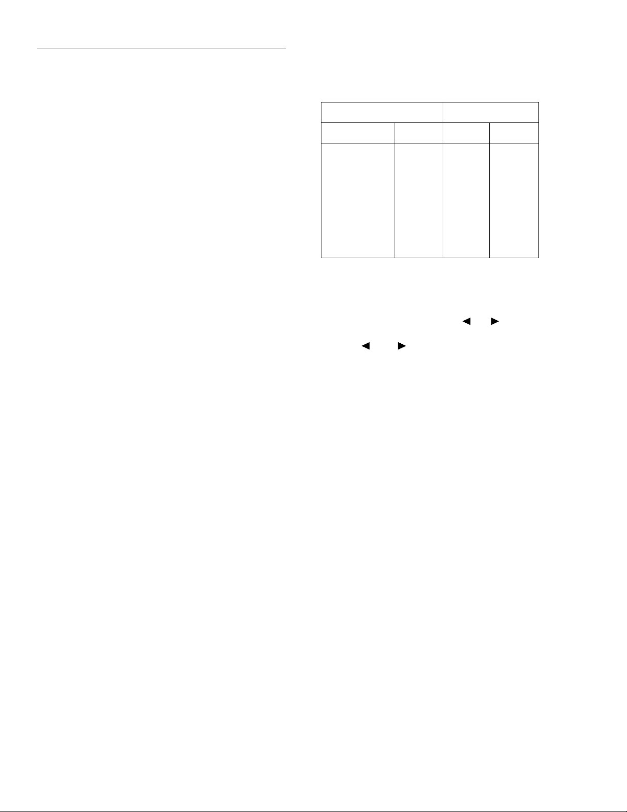
Front Panel Operation
Depending on the installed memory option, either one, five,
or ten user-defined setups can be stored, any one of which
could be selected as the power-on default.
Table 2-30 in paragraph 2.19.1 lists the default conditions
that are set at the factory to optimize bench and GPIB (IEEE-
488) operation.
2.2.5 Warm-up period
The Model 6517A can be used within one minute after it is
turned on. However, the instrument should be turned on and
allowed to warm up for at least one hour before use to
achieve rated accuracy.
2.2.6 IEEE-488 primary address
The IEEE-488 primary address of the instrument must be the
same as the primary address you specify in the controller's
programming language. The default primary address of the
instrument is 27, but you can set the address to any value
from 0 to 30 by using the MENU key. Refer to paragraph
2.19.2 for step-by-step instructions on setting the primary
address.
Table 2-4
Typical display exponent values
Engineering units Scientific notation
Value Display Value Display
Picoamperes
Nanocoulombs
Microamperes
Milliamps
Kilo-ohms
Mega-ohms
Giga-ohms
Tera-ohms
Peta-ohms
pA
nC
µA
mA
kΩ
MΩ
GΩ
TΩ
PΩ
-12
10
10-9C
10-6A
10-3A
103Ω
106Ω
109Ω
1012Ω
1015Ω
A
e-12A
e-9C
e-6A
e-3A
e3Ω
e6Ω
e9Ω
e12Ω
e15Ω
2.3.2 Information messages
Press the INFO key to view context-sensitive information
from most of the displays. An arrow ( or ) on the bottom line indicates that there is more information. Use the
cursor keys ( and ) to view the complete line. To exit
an INFO display, just press INFO, ENTER, EXIT or a function key.
Range messages
2.3 Display
The display of the Model 6517A is primarily used to display
readings along with the units and type of measurement.
When not displaying readings, it is used for informational
messages, such as menu headings and selections. At the top
of the display are annunciators to indicate various states of
operation.
2.3.1 Exponent mode (Engineering or Scientific)
Readings on the display can be expressed in engineering
units or in scientific notation as shown in Table 2-4. In the
scientific mode, the exponent can be fixed to a specified value, or it can be floating. In the floating mode, the instrument
will automatically select the exponent value.
All exponent mode selections are performed from the DISPLAY option of the GENERAL menu, which is part of the
MAIN MENU (see paragraph 2.19.7 for details).
The following display messages may occur when making
measurements:
OVERFLOW — This message is displayed when the integrated (average) input signal level (voltage, current, or
charge) exceeds 105% of full scale for the selected measurement range. For example, on the 20nA measurement range,
the OVERFLOW message occurs when the integrated input
level exceeds 21nA.
An OVERFLOW condition can be resolved by selecting a
higher measurement range, using AUTO range, or reducing
the magnitude of the input signal.
The OVERFLOW message will NOT occur during resistance or resistivity measurements.
UNDERFLOW — This condition is similar to OVERFLOW but pertains to resistance and resistivity measurements. An ohms measurement is performed by sourcing
voltage and measuring current. An ohms measurement that is
too low causes the current to exceed full scale. Thus, the
message UNDERFLOW is used to indicate that the measured resistance or resistivity is lower than the lo wer limit of
the selected range.
2-4
Page 26
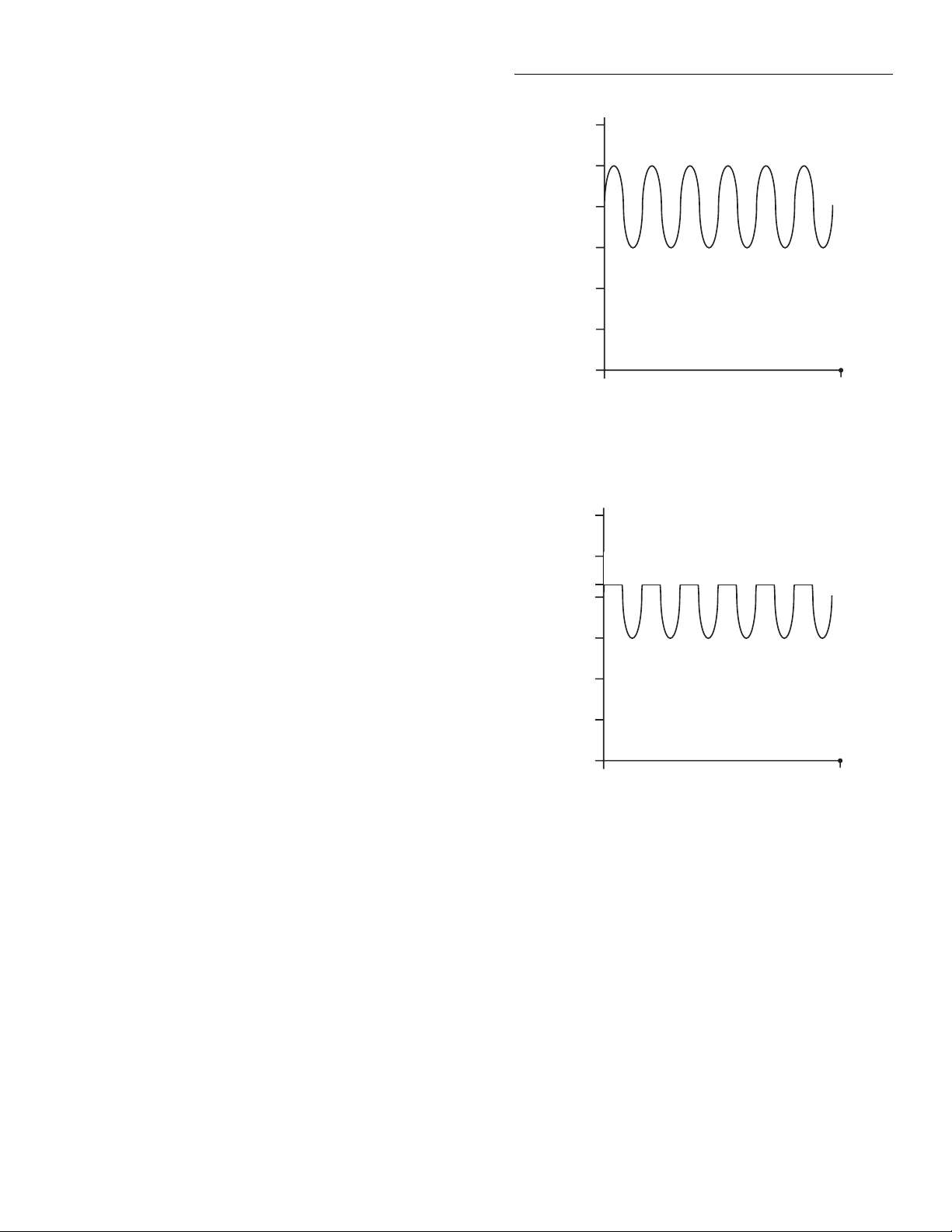
Front Panel Operation
The UNDERFLOW condition can usually be resolved by selecting a lower ohms range or by using AUTO range. Paragraph 2.7 (Ohms Ranges) covers range limits and explains
how to select the optimum range for ohms measurements.
OUT OF LIMITS — This message indicates that a momentary or transient out-of-range condition appeared at the input,
even though the integrated (or average) signal was within the
full scale range of the A/D con v erter. It usually indicates that
there is too much noise on the input signal for a valid measurement.
Generally, the OUT OF LIMITS condition can be eliminated
by better shielding of the signal source or by using other
noise reduction methods. Another solution is to select the
next higher range (or lower R range) to keep the transients
less than full scale.
The 2nA, 20nA, and 200nA ranges (and the R measurements
that use these current ranges) are particularly susceptible to
this condition because of the combination of speed and sensitivity.
A sine wave signal riding on a dc bias level is used to demonstrate an OUT OF LIMIT reading. Figure 2-A shows a
sine wave riding on a 20nA bias level. If this signal is measured on the 200nA range at normal speed, it would simply
read 20nA (which is the dc average). If howe v er, you use the
20nA range, the positive peaks of the sine wave will be
clipped as shown in Figure 2-B. Clipping occurs at 110% of
full range (22nA on the 20nA range). Because of clipping,
the measurement of the input signal is significantly less than
20nA. To avoid these bad readings, the Model 6517A displays the OUT OF LIMITS message instead of the inaccurate reading.
30
25
20
nA
15
10
Figure 2-A
Input signal
30
25
22
20
nA
15
10
DCA Reading on 200 nA range = 20nA
5
0
0
5
time 16.67ms
DCA Reading = <20nA
Note that the positive peaks of the input signal (which exceed
full scale) will not cause an OVERFLOW condition on the
20nA range since the average reading over the 16.67ms integration period is less than full scale.
The A/D hardware limit detection circuit can be disabled,
which in turn disables the OUT OF LIMITS message. However, the presence of OUT OF LIMIT readings may result in
measurements that are slightly, severely, or totally inaccurate. Paragraph 2.19.7 explains how to disable the OUT OF
LIMIT message.
When both OVERFLOW and OUT OF LIMITS conditions
occur, the OVERFLOW message will be displayed.
0
0
time 16.67ms
Figure 2-B
Measurement on 20nA range
2.3.3 Status and error messages
During Model 6517A operation and programming, you will
encounter a number of front panel messages. T ypical messages are either of status or error variety, as listed in Table 2-5.
The most recent status or error messages can be momentarily
displayed. Just enter a configuration menu or the main menu,
and press the PREV range key. (The display is blank if no
message is queued.)
2-5
Page 27

Front Panel Operation
Table 2-5
Status and error messages
Number Description Event
-440
-430
-420
-410
-350
-330
-314
-285
-284
-282
-281
-260
-241
-230
-224
-223
-222
-221
-220
-215
-214
-213
-212
-211
-210
-202
-201
-200
-178
-171
-170
-168
-161
-160
-158
-154
-151
-150
-148
-144
-141
-140
-128
-124
-123
“Query UNTERMINATED after
indefinite response”
“Query DEADLOCKED”
“Query UNTERMINATED”
“Query INTERRUPTED”
“Queue overflow”
“Self T est failed”
“Save/recall memory lost”
“Program syntax error”
“Program currently running”
“Illegal program name”
“Cannot create program”
“Expression Error”
“Hardware missing”
“Data corrupt or stale”
“Illegal parameter value”
“Too much data”
“Parameter data out of range”
“Settings conflict”
“Parameter Error”
“Arm deadlock”
“Trigger deadlock”
“Init ignored”
“Arm ignored”
“Trigger ignored”
“Trigger error”
“Settings lost due to rtl”
“Invalid while in local”
“Execution error”
“Expression data not allowed”
“Invalid expression”
“Expression error”
“Block data not allowed”
“Invalid block data”
“Block data error”
“String data not allowed”
“String too long”
“Invalid string data”
“String data error”
“Character data not allowed”
“Character data too long”
“Invalid character data”
“Character data error”
“Numeric data not allowed”
“Too many digits in number”
“Exponent too large”
EE
EE
EE
EE
EE
EE
EE
EE
EE
EE
EE
EE
EE
EE
EE
EE
EE
EE
EE
EE
EE
EE
EE
EE
EE
EE
EE
EE
EE
EE
EE
EE
EE
EE
EE
EE
EE
EE
EE
EE
EE
EE
EE
EE
EE
Table 2-5 (cont.)
Status and error messages
Number Description Event
-121
-120
-114
-113
-112
-111
-110
-109
-108
-105
-104
-103
-102
-101
-100
000 “No Error” SE
+101
+121
+122
+123
+124
+125
+126
+161
+171
+172
+173
+174
+301
+302
+303
+304
+305
+306
+307
+308
+309
+310
+311
+312
+313
+315
+320
+321
+322
“Invalid character in number”
“Numeric data error”
“Header suffix out of range”
“Undefined header”
“Program mnemonic too long”
“Command Header Separator Error”
“Command Header Error”
“Missing Parameter”
“Parameter not allowed”
“GET not allowed.”
“Data T ype Error”
“Invalid Separator”
“Syntax Error”
“Invalid Character”
“Command Error”
“Operation Complete”
“Device calibrating”
“Device settling”
“Device ranging”
“Device sweeping”
“Device measuring”
“Device calculating”
“Program running”
“Waiting in trigger Layer”
“Waiting in arm layer 1”
“Waiting in arm layer 2”
“Re-entering the idle layer”
“Reading overflow”
“Low limit 1 event”
“High limit 1 event”
“Low limit 2 event”
“High limit 2 event”
“Reading A vailable”
“Voltmeter Complete”
“Buffer A v ailable”
“Buffer half full”
“Buffer full”
“Buffer Overflow”
“Buffer Pretriggered”
“Reading out of Limit”
“V-Source compliance detected”
“Buffer & Format element mismatch”
“Buffer Sizing error; set to MAX”
“Buffer Sizing error; set to MIN”
EE
EE
EE
EE
EE
EE
EE
EE
EE
EE
EE
EE
EE
EE
EE
SE
SE
SE
SE
SE
SE
SE
SE
SE
SE
SE
SE
SE
SE
SE
SE
SE
SE
SE
SE
SE
SE
SE
SE
SE
SE
EE
EE
EE
2-6
Page 28
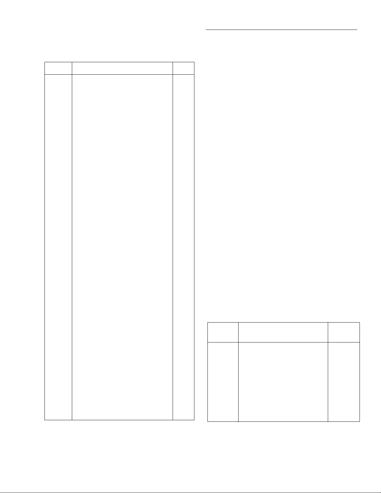
Front Panel Operation
Table 2-5 (cont.)
Status and error messages
Number Description Event
+350 to
427
+510
+511
+512
+513
+514
+515
+516
+517
+518
+519
+520
+521
+522
+610
+611
+612
+617
+618
Calibration commands (see Model
6517 Service Manual)
“Reading buffer data lost”
“GPIB address lost”
“Power-on state lost”
“Calibration data lost”
“Calibration dates lost”
“Calibration tolerances lost”
“Calibration tables lost”
“Voltage Offset lost”
“Current Offset lost”
“Installed option id lost”
“Option card not supported”
“Cal Card Data Error”
“GPIB communication language lost”
“Questionable Calibration”
“Questionable T emperature”
“Questionable Humidity”
“Questionable T est Sequence”
“Resistivity:I OutOfLimit”
EE
EE
EE
EE
EE
EE
EE
EE
EE
EE
EE
EE
EE
SE
SE
SE
SE
EE
+700 “Low Battery detected” EE
+800
+801
+802
+803
+804
+805
+806
+807
+808
+850
+851
+860
+861
“RS-232 Framing Error detected”
“RS-232 Parity Error detected”
“RS-232 Overrun detected”
“RS-232 Break detected”
“RS-232 Noise detected”
“Invalid system communication”
“RS-232 Settings Lost”
“RS-232 OFLO: Characters Lost”
“ASCII only with RS-232”
“Invalid Test Sequence Setting”
“Test Sequence Running”
“Interlock Violation Error”
"Vsource Limit too low for auto"
EE
EE
EE
EE
EE
EE
EE
EE
EE
EE
SE
EE
EE
+900 “Internal System Error” EE
+950
+951
+952
+953
+954
+955
+956
+957
+958
SE = Status event
EE = Error event
“DDC Reading overflow”
“DDC Reading Available”
“DDC Buffer full”
“DDC Mode IDDC Error”
“DDC Mode IDDCO Error”
“DDC Trigger Overrun Error”
“DDC No Remote Error”
“DDC Number Error”
“DDC Ready”
SE
SE
SE
EE
EE
EE
EE
EE
SE
2.3.4 Multiple displays
Each measurement function has its own set of “multiple displays” shown in the bottom line of the front panel display.
The PREVious and NEXT DISPLAY keys scroll through the
selections for the present function.
The multiple displays can show a reading in a different form,
or give additional information about the reading, for example:
•Top line shows a reading; bottom line shows a zero-center bar graph with adjustable limits.
To scroll through the multiple displays available for each
measurement functions, repeatedly press and release the
NEXT DISPLAY key. The same action with the PREVious
DISPLAY key does a reverse scroll through the displays. To
return to the default reading display, just press and hold either key.
Multiple displays that are specific to a particular function or
operation are discussed later in this section, such as the calculations display in math (see Table 2-6 for paragraph references). Some of the displays that are common to all
measurement functions are discussed here.
Time/Day/Date
This display provides the time, day of week, and the date.
The time, date and format (12-hour or 24-hour) are set from
the CLOCK option of the GENERAL MENU (which is selected from the MAIN MENU). See paragraph 2.19.7
(CLOCK) for details.
Table 2-6
Multiple (Next) displays by function
Paragraph
Function Next display
All Time, day and date
Bar graph
Zero-centered bar graph
Maximum and minimum values
Relative and actual values
Calculated and actual values
Limits bar graph
Relative humidity and external
temperature stamp
R Source (V) and measure (I) values 2.7.4
reference
2.3.4
2.3.4
2.3.4
2.3.4
2.13.3
2.18.7
2.19.5
2.3.4
2-7
Page 29
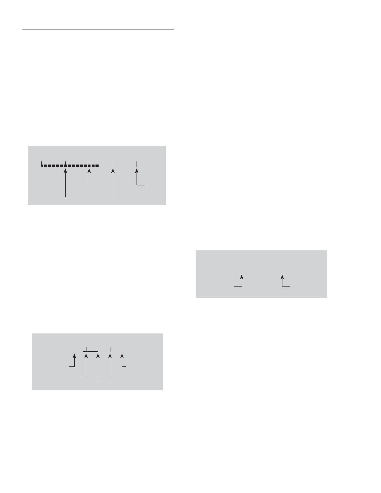
Front Panel Operation
Bar graph
The “normal” bar graph, with a zero at the left end, is a
graphical representation of a reading as a portion of a range.
(See Figure 2-2.) The vertical lines displayed along the bar
designate 0%, 25%, 50%, 75%, and 100% of full scale. Each
full segment of the bar represents approximately 4% of the
range limit.
The right endpoint of the bar graph is plus full scale of the
present range for positive readings, and minus full scale for
negative readings. When the 100% line changes to an arrow,
the reading exceeds the present range.
-11.9685
0
25% of
full range
V
-20V
Full
Range
50% of
full range
75% of full range
Figure 2-2
Bar graph (zero-at-left) multiple display
Zero-centered bar graph
wise, values greater than 1% (such as 1.67%) are shown
rounded to the nearest integer percent.
Perform the following to view or change the plus and minus
percentage of range:
1. From a measurement function, press CONFIG and then
NEXT or PREV DISPLAY . The follo wing is displayed:
ZERO-BARGRAPH+/-50.00%
2. Change the percentage by using the cursor keys and the
RANGE ▲ and ▼ keys to enter a numeric value (0.01 -
99.99%). Press ENTER when done.
Maximum and minimum
The maximum and minimum multiple display shows the
maximum and minimum readings since the display was entered. (See Figure 2-4.) The maximum and minimum values
are reset by the following:
• Pressing the present function key.
• Leaving the display by changing function or entering a
menu.
The resolution, units, and prefix on the bottom line are the
same as shown for top line reading.
The zero-centered bar graph is a graphical representation of
a reading with plus and minus limits. (See Figure 2-3.) The
limits are expressed in a user-selectable percentage of range.
The vertical lines displayed along the bar designate the plus
and minus limits, zero, and halfway to either limit. There are
ten full segments between zero and each end, so each full
segment represents 10% of the limit. When a line at the limit
changes to an arrow, the reading exceeds the programmed
range.
-05.9577
50%
-50% of range
-25% of range
V
+50V
+50% of range
25% of range
0%
Figure 2-3
Zero-centered bar graph multiple display
The plus and minus percentage of range that is programmed
(0.01 - 99.99%) applies to all functions. Because of rounding, values greater than 99.5% are shown as 100% and, like-
-15.8286
Max = -05.7460
Maximum
value
V
Min = -15.8286
Minimum
value
Figure 2-4
Maximum and minimum multiple display
Relative humidity and external temperature
This display provides the relative humidity and the external
temperature readings. Note that the appropriate sensors have
to be connected to instrument, and they have to be enabled in
order to get valid readings. (See paragraph 2.22 for details.)
2.3.5 Navigating menus
There are basically two types of menu structures; the Main
Menu and the Configure menus. The Main Menu accesses
items for which there are no dedicated keys, and Configure
menus are used to configure measurement functions and other instrument operations.
2-8
Page 30

Front Panel Operation
Use the following rules to navigate through the menu structure:
1. The top level of the Main Menu is accessed by pressing
the MENU key. A Configuration menu is accessed by
pressing CONFIG and then the desired function (V, I,
etc.) or operation (TRIG, STORE, etc.).
2. A menu item is selected by placing the cursor on it and
pressing ENTER. Cursor position is denoted by the
blinking menu item or parameter. The cursor keys (
and ) control cursor position.
3. A displayed arrow ( and ) on the bottom line indicates that there are one or more additional items (messages) to select from. Use the appropriate cursor key to
display them.
4. A numeric parameter is keyed in by placing the cursor
on the digit to be changed and using the RANGE ▲ or
▼ key to increment or decrement the digit.
5. A change is only executed when ENTER is pressed. Entering an invalid parameter generates an error and the
entry is ignored.
6. The EXIT key is used to back out of the menu structure.
Any change that is not entered is cancelled when EXIT
is pressed. The EXIT key has additional actions and are
summarized in Table 2-7.
7. The VOL T A GE SOURCE ▼ and ▲ keys are used adjust
the V-Source value. The V-Source is decremented or incremented by placing the cursor on the desired digit and
pressing ▼ or ▲. With the cursor on the polarity sign,
pressing ▼ or ▲ toggles the polarity. Pressing CONFIG
and then ▼ or ▲ displays the CONFIGURE VSOURCE menu.
2.4 Connections — electrometer, highresistance meter , and V -source
ing. The concepts of guarding and floating circuits are
introduced here.
NOTE
Detailed connection schemes are included
with the measurement procedures (see
paragraphs 2.5.1, 2.6.1, 2.7.1 and 2.8.1).
2.4.1 Electrometer input connector
The rear panel triax INPUT connector is a 3-lug female triax
connector that will mate to a cable terminated with a 3-slot
male triax connector.
Input configurations — As shown in Figure 2-5, the input
connector can be configured in two ways. With GUARD off
(Figure 2-5A), input low is connected to the inner shell of the
connector. This configuration is used for current, resistance,
coulombs and unguarded voltage measurements.
NOTE
Where possible, make input low connections directly to the INPUT connector low
terminal instead of using COMMON to
avoid internal voltage drops that may affect measurement accuracy.
With GU ARD on (Figure 2-5B), guard is connected to the inner shell of the triax connector. Input low is accessed via the
COMMON binding post through an internal 1Ω resistor.
This configuration is used for guarded voltage measurements
only. Note that guard can only be enabled (on) for the volts
function. For ohms, amps and coulombs, guard is always disabled (off). For voltage measurements, guard is enabled or
disabled from the Configure Voltage menu structure as explained in paragraph 2.5.2.
The following information provides basic information on
electrometer, high-resistance meter, and V-source connections. Also co vered is the use of lo w-noise cables and shield-
Table 2-7
EXIT key actions
Condition EXIT key action
Temporary message displayed
(e.g., TRIGGERS HAL TED)
INFO message displayed
Reading display hold
Scanning
Data storage
Cancels display of temporary message.
Cancels INFO message, returns to menu or normal reading display.
Cancels reading display hold, resumes normal reading display.
Disables scanning. Also stops data storage if enabled.
Stops data storage. Temporary message STORAGE INTERRUPTED
is displayed.
The INPUT triax connector is also used for the Force Voltage
Measure Current configuration. This configuration utilizes
the V-source to make resistance measurements (see paragraph 2.4.2) and current measurements (see paragraph
2.4.3).
2-9
Page 31

Front Panel Operation
INPUT
250V PEAK
Volts, Amps, Ohms & Coulombs
A. Unguarded (GUARD off)
Input High
Guard
Chassis
INPUT
250V PEAK
Volts only
Ground
B. Guarded (GUARD on)
Figure 2-5
Input connector configurations
Input High
Input Low
Chassis Ground
COMMON
1Ω
Input Low
Input High
Input Low
Chassis Ground
* Max Input Signal - 250VRMS, DC to 60Hz sine wave
(10 seconds maximum in mA ranges).
Figure 2-6
Maximum input levels
S
V
Max Input Signal *
500V Peak
Capacitor
Under Test
500V Peak
6517A
A
Ammeter
Maximum input levels — The maximum input lev els to the
Model 6517A are summarized in Figure 2-6.
WARNING
The maximum common-mode input
voltage (the voltage between input low
and chassis ground) is 500V peak. Exceeding this value may create a shock
hazard.
CAUTION
Connecting PREAMP OUTPUT, COMMON, or 2V ANALOG OUTPUT to
earth while floating the input may damage the instrument.
Input protection — The Model 6517A incorporates protec-
tion circuitry against nominal overload conditions. Howe ver ,
a high voltage (>250V) and resultant current surge could
damage the input circuitry. A typical test circuit to measure
the leakage current of a capacitor is shown in Figure 2-7.
When Switch S is closed, an initial surge of charging current
will flow and the high voltage will be seen across the input
of the Model 6517A.
Figure 2-7
Capacitor test circuit without protection
Adding a resistor and two diodes (1N3595) as shown in Figure 2-8 will provide considerable extra protection. The resistor must be large enough to limit the current through the
diodes to 10mA or less. It must also be large enough to withstand the supply voltage. The protection circuit should be enclosed in a light-tight conductive shield.
This same protection circuit is useful when measuring the insulation resistance of films or high-voltage cables. Without
such added protection, a pinhole or other defect could cause
an arc, destroying the electrometer input.
Protection Circuit
S
Capacitor
Under Test
V
R
D1 D2
HI
A
LO
6517A
Ammeter
Figure 2-8
Capacitor test circuit with protection
2-10
Page 32

Front Panel Operation
Figure 2-10
V-source output
2.4.2 High-resistance meter connections
The Model 6517A uses the Force Voltage Measure Current
(FVMI) configuration to measure resistance. From the
known voltage and measured current, the resistance is calculated (R = V/I) and displayed.
The resistance to be measured is connected to the center conductor of the INPUT triax connector and the V SOURCE
OUT HI binding post as shown in Figure 2-9A. This configuration assumes that V-Source LO is internally connected to
ammeter LO via the METER-CONNECT option of the
CONFIGURE V-SOURCE menu structure (see paragraph
2.9.1). The equivalent circuit for this configuration is shown
in Figure 2-9B.
WARNING
The maximum common-mode voltage
(the voltage between V-Source/Electrometer LO and chassis ground) is
500V peak. Exceeding this value may
create a shock hazard.
2.4.3 Voltage source output connections
The voltage source output is accessed at the rear panel V
SOURCE OUT HI and LO binding posts as shown in Figure
2-10A. Using these terminals simply places the independent
V-Source in series with the external circuit (RL) as shown in
Figure 2-10B.
The V-Source can also be used be with the Electrometer to
form the Force Voltage Measure Current (FVMI) configuration as shown in Figure 2-9. This configuration is used for resistance measurements (see paragraph 2.4.2) and current
measurements. For these measurements, V-Source LO and
ammeter input LO can be connected internally via the
METER-CONNECT option of the CONFIGURE VSOURCE menu (see paragraph 2.9.1).
WARNING
The maximum common-mode voltage
(the voltage between voltage source low
and chassis ground) is 750V peak. Exceeding this value may create a shock
hazard.
LO
INPUT
250V PEAK
Note: V-SOURCE LO connected to ammeter input LO
via METER-CONNECT option of CONFIGURE
V-SOURCE Menu.
A. Basic connections
Ammeter
LO
A
B. Equivalent circuit
Figure 2-9
Force voltage measure current
R
V-Source
R
V SOURCE
OUT
HI
LO
V-Source Out
R
L
A. Basic connections
V-Source
HIHI
LO HI
R
L
B. Equivalent Circuit
HI
2-11
Page 33

Front Panel Operation
V-source probes and cables
The following probe and cable sets are available from Keithley as options:
• Model 8606 High Performance Probe Tip Kit: Con-
sists of two spade lugs, two alligator clips, and two
spring hook test probes. (The spade lugs and alligator
clips are rated at 30V RMS, 42.4V peak; the test probes
are rated at 1000V.) These components are designed to
be used with high performance test leads terminated
with banana plugs, such as the Model 8607 Performance Banana Cables.
• Model 8607 High Performance Banana Cables: Con-
sists of two high voltage (1000V) banana cables. The
cables are terminated with banana plugs that have retractable sheaths.
2.4.4 Low noise cables, shielding, and guarding
When making precision measurements, you should always
use low noise cables and, when feasible, utilize proper
shielding and guarding techniques.
Low noise input cables
Triax cables can generate enough triboelectric currents to
corrupt the measurement. These currents are caused by friction between the center conductor and the inner shield when
the cable is flexed or allowed to mo ve around. The use of lo w
noise cables help minimize these triboelectric currents. See
paragraph 2.21.2 for more information on minimizing triboelectric currents.
The following low noise cables are recommended for use
with the Model 6517:
• Model 237-ALG-2 — This 2-meter low noise triax cable is terminated with a 3-slot male triax connector on
one end and three alligator clips on the other end. The
alligator clip with the red boot is connected to the center
conductor (input high). The black booted clip is connected to the inner shield (input low or guard). The
green booted clip is connected to the outer shield (chassis ground).
• Model 7078-TRX-3 — This 3-foot low noise triax cable is terminated with a 3-slot male triax connector on
either end.
• Model 7078-TRX-10 — This is the same as the Model
7078-TRX-3 except that it is 10 feet in length.
• Model 7078-TRX-20 — This is the same as the Model
7078-TRX-3 except that it is 20 feet in length.
Notes:
1. For voltage measurements, the increased input capacitance caused by a long input cable can significantly slow
down the reading response. To minimize this problem,
always use the shortest possible triax input cable and/or
use guarding.
2. For current and resistance measurements, the increased
input capacitance caused by a long input cable can result
in noisy readings. T o minimize this problem, al ways use
the shortest possible triax input cable and/or enable
damping (see paragraphs 2.6.2 and 2.7.2). Damping will
reduce the noise but it will also slow do wn the response
time of the measurement.
Shielding and guarding
The following information covers the basics on using noise
shields, guard shields and safety shields.
Noise shield — A noise shield is used to prevent unwanted
signals from being induced on the electrometer input. Effective shielding encloses the device or circuit under test and e xtends to the electrometer input via a triax cable. The generic
connection for the noise shield is shown in Figure 2-11
which also summarizes the measurements that may benefit
from it.
Metal Noise Shield
Connect to 6517A LO, chassis ground
Device or
Circuit
Under
Test
or both (via triax cable)
Use Noise shield for:
1) Unguarded voltage measurements
2) Unguarded current measurements
(below 1µA)
3) Low level charge measurements
Figure 2-11
Noise shield
Typically, the noise shield is connected to electrometer input
LO. However, sometimes better noise performance can be
achieved by instead connecting the noise shield to both electrometer LO and chassis ground. Electrometer LO can be
connected to chassis ground at the rear panel of the Model
6517 by installing the ground link between the COMMON
binding post and the chassis ground binding post. You may
have to experiment to determine which method provides the
best noise performance.
2-12
Page 34

Front Panel Operation
Use safety shielding whenever
≥30V is present on the guard or
noise shield. Guarded measurements and floating measurements
can place hazardous voltages on
the guard/noise shield.
Connect to 6517A chassis
ground (via triax cable)
Device or
Circuit
Under
Test
Noise or Guard Shield
Safety
Earth
Ground
Metal
Safety
Shield
* Connect the safety shield to safety earth ground
using #18 AWG wire or larger.
Figure 2-13
Safety shield
CAUTION
Do not make floating measurements
with electrometer LO connected to chassis ground. If the rear panel ground link
is installed between COMMON and
chassis ground, remove it before floating
the instrument.
Guard shield — Guarding is used to greatly reduce leakage
current in a high impedance test circuit. Leakage resistance
exists in the input cable (between conductor paths) and in the
test fixture (at connectors and insulators). The concept of
guarding is to surround the input high node or DUT with a
guard shield that is at the same potential. Current cannot flow
through a leakage resistance that has a 0V drop across it. The
generic connection for the guard shield is shown in Figure 212, which also summarizes the measurements that guard is
used for. Notice that a safety shield is also used since guarded measurements can place hazardous voltages on the guard
shield (see Safety Shield).
Metal Safety Shield
Metal Guard Shield
For floating current measurements, a unique guard technique
is used in a high impedance test circuit where significant
leakage current may exist between the ammeter input and
test circuit common. This unique guard technique for floating current measurements is explained in paragraph 2.6.3
(Guarding) and is shown in Figure 2-31.
Safety shield — A safety shield is required whenever a hazardous voltage is present on the noise shield or guard shield,
or when a test circuit is floated above earth ground at a hazardous voltage level (see paragraph 2.4.5). A shock hazard
exists at a voltage level equal to or greater than 30V rms.
Hazardous voltages up to 500V may appear on the noise/
guard shield when performing floating measurements or
guarded measurements.
The generic connections for the safety shield are shown in
Figure 2-13. The metal safety shield must completely surround the noise or guard shield, and must be connected to
safety earth ground using #18 AWG or larger wire.
Device or
Circuit
Under
Test
Safety
Earth
Ground
Use Guard for:
1) Guarded voltage measurement
2) Guarded, floating current measurements
Connect to 6517A Guard
(via triax cable)
Figure 2-12
Guard shield
For voltage measurements, guarding should be used when
the test circuit impedance is ≥1GΩ or when long input cables
are used. Guard is enabled from the Configure Voltage menu
structure (see paragraph 2.5.2). When enabled, the guard potential is placed on the inner shield of the triax input cable.
Figure 2-21 in paragraph 2.5.1 shows detailed connections
for guarded voltage measurements. See paragraph 2.5.3
(Guarding) for more information on guard.
For current measurements, guarding should be used when
the test circuit impedance ≥1GΩ. Significant leakage could
occur across a DUT through insulators and corrupt the measurement. Input LO (inner shield of the input triax cable) is
used as the guard. Paragraph 2.6.3 (Guarding) explains how
guarding affects high impedance current measurements and
is shown in Figure 2-30.
2.4.5 Floating circuits
Many measurements are performed above earth ground and,
in some test situations, can result in safety concerns. Figure
2-14 shows two examples where the Model 6517A floats at
a hazardous voltage level. In Figure 2-14A, a shock hazard
(100V) exists between meter input LO and chassis ground. If
meter input LO is connected to a noise shield, then the shock
hazard will also be present on that shield. In Figure 2-14B, a
shock hazard (200V) exists between the meter input (HI and
LO) and chassis ground. If meter input LO is connected to a
noise or guard shield, then the shock hazard will also be
present on that shield.
2-13
Page 35

Front Panel Operation
+
R
200V
-
(R
= R2)
1
A. Voltage measurement
+
200V
-
R
B. Current measurement
Figure 2-14
Floating measurements
HI
6517A
V
1
Voltmeter
LO
The maximum voltage (common-mode)
between electrometer LO and chassis
ground is 500V. The maximum voltage
WARNING
between V-Source LO and earth (chas-
R
2
100V
sis) ground is 750V. Exceeding these values may create a shock hazard.
WARNING
When floating input LO above 30V from
earth (chassis) ground, hazardous voltage will be present at the analog outputs
6517A
R
1
R
A
Ammeter
3
(PREAMP OUTPUT and 2V ANALOG
OUTPUT). Hazardous voltage may also
be present when the input voltage exceeds 30V in the volts function.
2
200V
CAUTION
Connecting PREAMP OUTPUT, COMMON or 2V ANALOG OUTPUT to
earth (chassis) ground while floating the
input may damage the instrument.
The V-Source of the Model 6517A can also be operated
above earth ground as shown in Figure 2-15. In this circuit,
the V-Source is floating 100V above ground. Thus, a shock
hazard (100V) exists between V-Source LO and chassis
ground. A shock hazard exists at a voltage level equal to or
greater than 30V rms. To avoid possible shock hazards, always surround exposed floating circuits and shields with a
safety shield as explained in paragraph 2.4.4 (Safety Shield).
100V
Figure 2-15
Floating V-sour ce
HI
LO
100kΩ
6517A
V-Source
200V
100kΩ
2-14
Page 36

Front Panel Operation
2.4.6 T est fixtures
Whenever possible, use shielded, low leakage test fixtures to
make precision measurements.
Keithley test fixtures
Keithley offers a variety of different test fixtures. The ones
that are typically used with the Model 6517A are described
as follows.
Model 8002A High Resistance Test Fixture — This test fixtures allows resistance measurements as high as 1015Ω. Features include:
•A 3-lug triax connector and dual binding posts make
connections to the Model 6517A simple.
•Two in-line DUT connection posts that are mounted on
a guard plate.
• Light-free environment for light sensitive DUT.
• Safety Interlock. When connected to the Model 6517A,
voltage cannot be sourced to the test fixture when the lid
is open.
• Screw terminal on test fixture chassis for connection to
safety earth ground.
Note: Figure 2-33 in paragraph 2.7.1 shows connections to
the Model 6517A and the equivalent circuit.
Model 8009 Resistivity Test Fixture — This test fixture allows volume resistivity in the range from 103 to 1018Ω-cm,
and surface resistivity in the range from 103 to 1017Ω/sq.
Features include:
•A 3-lug triax connector and dual binding posts make
connections to the Model 6517A simple.
• Guarded electrodes that can accommodate samples up
the ⅛" thick and 4" × 4".
• Safety Interlock. When connected to the Model 6517A,
the V-Source goes into standby when the test fixture lid
is open.
• Screw terminal on test fixture chassis for connection to
safety earth ground.
Note: Figure 2-37 in paragraph 2.7.1 shows connections to
the Model 6517A and the equivalent circuit.
Custom built test fixtures
Two examples of custom built test fixtures are shown in Figures 2-16 and 2-17. The first is a dedicated test fixture to
source voltage and measure current to a single DUT (resistance measurements). The second is a multi-purpose test fixture that can be used to make any Model 6517A measurement.
These two examples illustrate the basic techniques that should
be applied when building a test fixture. These same basic techniques should be used if you need to build a more complex test
fixture to accommodate your test measurement requirements.
The test fixture in Figure 2-16 assumes that ammeter input
LO is connected to V-Source LO inside the Model 6517A.
This LO-to-LO connection is controlled from the METER
CONNECT selection in the CONFIGURE V-SOURCE
menu (see paragraph 2.9.1).
The following requirements, recommendations and guidelines are provided in order to build a quality test fixture that
is safe to use.
NOTE
After building a test fixture you should
clean it (see Handling and Cleaning Test
Fixtures).
Test fixture chassis
1. The chassis of the test fixture should be metal so that it
can function as a shield for the DUT or test circuit
mounted inside. The chassis of the test fixture will be
connected to chassis ground of the Model 6517A via the
triax cable.
2. The test box must have a lid that closes to prevent contact with live circuitry inside.
WARNING
Safe operation requires that a safety interlock switch be used to place the VSource in standby when the test fixture
lid is open or ajar (see Interlock).
3. The test fixture chassis must have a screw terminal that
is used exclusively for connection to safety earth
ground.
WARNING
To provide protection from shock hazards, the test fixture chassis must be
properly connected to safety earth
ground. A grounding wire (#18 AWG or
larger) must be attached securely to the
test fixture at a screw terminal designed
for safety grounding. The other end of
the ground wire must be attached to a
known safety earth ground.
2-15
Page 37

Front Panel Operation
Guard plate
A metal guard plate will provide guarding or noise shielding
for the DUT or test circuit. It will also serve as a mounting
panel for DUT or test circuits. The guard plate must be insulated with 1000V spacing from the chassis of the test fixture.
Connectors, terminals and internal wiring
Figures 2-16 and 2-17 show the types of connectors needed
to use the test fixtures with the Model 6517A. All connectors,
except the triax connector, must be insulated from the chassis
of the test fixture. The outer shell of the triax connector must
be referenced to chassis ground. Thus, DO NOT insulate the
outer shell of the triax connector from the metal chassis of
the test fixture.
DUT and test circuits are to be mounted on the guard plate
using insulated terminals. T o minimize leakage, select terminals that use virgin Teflon insulators.
Inside the chassis of the test fixture, you may use coaxial cable to extend guard from the triax connector to the DUT . The
shield (guard) of the cable should extend as far as possible to
the DUT.
graph 2.9.4 for more information on the interlock feature of
the Model 6517A.
NOTE
An "Interlock Violation Error" message
will be displayed when the interlock is
open.
The switch must be mounted inside the test box such that it
will be closed when the lid of the test fixture is closed. Opening the lid must cause the interlock switch to open. There
must never be enough clearance to allow finger access inside
the box while the switch is closed. The interlock must be designed so that it cannot be defeated.
By using an appropriate bulkhead connector on the test fixture, the Keithley Model 6517-ILC-3 Interlock cable can be
used to connect the interlock switch to the Model 6517A (see
Figure 2-18A). The connector needed is shown in Figure 218C. Figure 2-18B shows the dimensions of the hole that
must be cut into the test fixture chassis to mount the connector. Figure 2-18D sho ws how to wire the connector to the test
fixture interlock switch.
Interlock
When a normally-open, SPST momentary switch is properly
implemented as a safety interlock, the V-Source will go into
standby whenever the test fixture lid is open or ajar . See para-
Interlock Switch
1
To 6517A
Interlock
To 6517A
V Source
Out HI
To 6517A
Input
2
A
3
4
B
C
A
B
C
Open Lid = Open Switch
DUT
Guard Plate
Interlock Connector
Banana Jack
3-Lug Female Triax Connector
As an alternative, you can remove one of the plugs from the
Model 6517-ILC-3 and hard wire the interlock cable directly
to the interlock switch of the test fixture as shown in Figure
2-19.
Insulated
Terminal
Post (2)
Screw Terminal for
Safety Earth Ground
Warning: Test fixture must
be connected to safety earth
ground using #18 AWG wire
or larger.
Figure 2-16
Test fixture to source voltage, measure current (resistance measurements)
2-16
Page 38

To 6517A
Interlock
To 6517A
V Source
Out
Front Panel Operation
Interlock Switch
1
2
A
3
4
B
Open Lid = Open Switch
Guard Plate
Insulated
Terminal
Post (5)
Figure 2-17
Multi-purpose test fixture
To 6517A
Input
To 6517A
Common
C
D
6517A
DUT
or
Test
Circuit
Interlock Connector
A
Dual Banana Jacks
B
3-Lug Female Triax Connector
C
Banana Jack
D
Screw Terminal for
Safety Earth Ground
Warning: Test fixture must
be connected to safety earth
ground using #18 AWG wire
or larger.
Figure 2-18
Interlock connections
Interlock
+.004
.444
-.000
+.004
.196
.422
-.000
B. Panel cutout dimensions
Interlock Cable
A. Interlock Connection to Unit
#3
Side View
#4
View from inside
of test box
Keithley P/N : CS-659 (3-pin)
CS-459 (4-pin)
Switchcraft P/N :
TB3M (3-pin)
TB4M (4-pin)
Interlock
Connector
#1
#2
Test Fixture
Normally-open SPST
Momentary Switch
Open lid = Open Switch
D. Interlock WiringC. Interlock Connector:
2-17
Page 39

Front Panel Operation
Interlock
6517-ILC-3 Cable*
6517A
* Plug at test fixture end of cable removed
Strain relief for cable
Clear
Black
Test Fixture
Normally-Open
SPST Momentary
Switch
Figure 2-19
Hard-wired interlock
Handling and cleaning test fixtures
Dust, body oil, solder flux and other contaminants on connector and terminal insulators can significantly decrease the
leakage resistance resulting in excessive leakage currents.
Also, contaminants on DUT and test circuit components can
create a leakage path. These leakage currents may be large
enough to corrupt low-level measurements.
Handling tips:
• Do not touch the bodies of DUT or test circuit components. If you cannot handle them only by their leads, use
clean cotton gloves to install them in the test fixture.
• Do not touch any connector or terminal insulator.
• If installing a test circuit that is on a pc-board, handle
the board only by the edges. Do not touch any board
traces or components.
Cleaning tips:
• Use dry nitrogen gas to clean dust off of connector and
terminal insulators, DUT and other test circuit components.
• If you have just built the test fixture, remo ve any solder
flux using methanol along with clean foam-tipped
swabs or a clean soft brush. Clean the areas as explained
in the next tip.
•To clean contaminated areas, use methanol and clean
foam-tipped swabs. After cleaning a large area, you
may want to flush the area with methanol. Blow dry the
test fixture with dry nitrogen gas.
• After cleaning, the test fixture (and any other cleaned
devices or test circuits) should be allowed to dry in a
50°C low-humidity environment for several hours.
2.5 Voltage measurements
The Model 6517A can make unguarded or guarded voltage
measurements from 1µV to 210V. Guard should be used if response time or leakage resistance is a consideration. The concepts of guarding are discussed in paragraphs 2.4.4 and 2.5.3.
2.5.1 Basic measurement procedure
The voltage measurement procedure is summarized as follows:
NOTE
To ensure proper operation, always enable
zero check ("ZeroCheck" displayed) before changing functions (V, I, R, or Q).
The Z-CHK key controls zero check.
1. With zero check enabled (“ZeroCheck” displayed), select the volts (V) function. The Z-CHK key toggles zero
check between the on and off states.
NOTE
The input circuit configuration changes
with zero check enabled. See paragraph
2.13 for details.
2. Enable or disable guard as needed. Guard is controlled
from the GUARD option of the Voltage Configuration
menu (see paragraph 2.5.2).
NOTE
The “Grd” message on the display indicates that guard is enabled (on).
3. To achieve optimum accuracy for low voltage measurements, it is recommended that you zero correct the instrument. To do so, select the lowest measurement range (2V)
and press REL. The REL indicator turns on and the
“ZCor” message is displayed. Correcting zero on the lowest range will correct all ranges because of internal scaling.
NOTE
If guard is enabled, the “ZCor” message
will replace the “Grd” message. Keep in
mind that guard is still enabled even
though the “Grd” message is not displayed.
2-18
Page 40

Front Panel Operation
Red (HI)
Black (LO)
6517A
Shield (Optional)
Vs
Measured
Voltage
+
-
CAUTION:FOR CONTINUED PROTECTION AGAINST FIRE HAZARD,REPLACE FUSE WITH SAME TYPE AND RATING.
CAUTION:FOR CONTINUED PROTECTION AGAINST FIRE HAZARD,REPLACE FUSE WITH SAME TYPE AND RATING.
WARNING:NO INTERNAL OPERATOR SERVICABLE PARTS,SERVICE BY QUALIFIED PERSONNEL ONLY.
WARNING:NO INTERNAL OPERATOR SERVICABLE PARTS,SERVICE BY QUALIFIED PERSONNEL ONLY.
237-ALG-2
Cable
INPUT
250V PEAK
COMMON
TRIGGER
LINK
IN OUT
!
LINE RATING
90-134VAC
180-250VAC
50, 60, 400HZ
55VA MAX
LINE FU
SLOWBL
1/2A, 250
IEEE-488
(CHANGE IEEE ADDRESS
WITH FRONT PANEL MENU)
A. Connections
B. Equivalent circuit
Figure 2-20
Typical connections for unguarded voltage measurements
4. Select a manual measurement range that is consistent
with the expected reading, or enable auto range (see
paragraph 2.12 for detailed range information).
5. Connect the Model 6517A to the voltage to be measured. Figure 2-20 shows typical connections for unguarded measurements, and Figure 2-21 shows typical
connections for guarded measurements.
WARNING
Hazardous voltage may be present on
the inner shield of the triax cable when
GUARD is on. A safety shield connect-
ed to safety earth ground (as shown in
Figure 2-21) should be used for voltage
measurements at or above 30V.
6. Press Z-CHK to disable zero check and take a reading
from the display.
NOTE
To disable zero correct, enable zero check
and press REL.
+
Vs
-
HI
LO
+
-
GND
S
PREAMP OUTPUT
COMMON
2V ANALOG OUTPUT
1Ω
Ranging
Amp
To A/D
+
S
S
Converter
2-19
Page 41

Front Panel Operation
CAUTION:FOR CONTINUED PROTECTION AGAINST FIRE HAZARD,REPLACE FUSE WITH SAME TYPE AND RATING.
CAUTION:FOR CONTINUED PROTECTION AGAINST FIRE HAZARD,REPLACE FUSE WITH SAME TYPE AND RATING.
WARNING:NO INTERNAL OPERATOR SERVICABLE PARTS,SERVICE BY QUALIFIED PERSONNEL ONLY.
WARNING:NO INTERNAL OPERATOR SERVICABLE PARTS,SERVICE BY QUALIFIED PERSONNEL ONLY.
-
E
P
Measured
Voltage
6517A
237-ALG-2
Red (HI)
+
-
Black (LO)
Vs
Green
(LO)
Cable
!
INPUT
250V PEAK
COMMON
IN OUT
TRIGGER
LINK
LINE RATING
90-134VAC
180-250VAC
50, 60, 400HZ
55VA MAX
(CHANGE IE
WITH FRONT
IEEE
Safety
Earth
Ground
A. Connections
B. Equivalent circuit
Guard
+
Vs
-
Safety Shield
Input
HI
GUARD
GND
150kΩ
PREAMP OUTPUT
COMMON
1Ω
2V ANALOG OUTPUT
+
-
Input
Amp
Ranging
Amp
-
+
S
S
To A/D
Converter
Figure 2-21
Typical connections for guarded voltage measurements
2-20
Page 42

Front Panel Operation
Table 2-7
CONFIGURE VOLTS menu structure
Menu item Description
GUARD Enable or disable guard.
EXT-FDBK Enable or disable external feedback mode.
SPEED
NORMAL
FAST
MEDIUM
HIACCURACY
SET-SPEED-EXACTLY
SET-BY-RSLN
Measurement speed (integration time) menu:
Select 1 PLC (power line cycle, 16.67msec for 60Hz, 20msec for 50Hz and 400Hz).
Select 0.01 PLC.
Select 0.1 PLC.
Select 10 PLC.
Set integration in PLC (0.01-10).
Default to setting appropriate for resolution.
FILTER
AVERAGING
TYPE
NONE
AVERAGING
ADVANCED
AVERAGING-MODE
MEDIAN
DISABLE
ENABLE
Filter menu:
Configure digital averaging filter:
Select type of average filter:
No average filtering performed.
Program a simple average filter (1-100 rdgs).
Program a simple average filter (1-100 rdgs). with noise tolerance window (0-
100% of range).
Select moving average or repeating average mode.
Configure median filter:
Disable median filter.
Enable median filter and specify range (1-5).
RESOLUTION
AUTO
3.5d, 4.5d, 5.5d, 6.5d
Display resolution menu:
Default to resolution appropriate for integration time.
Select a specific resolution.
2.5.2 Volts configuration
The following information explains the various configuration options for the volts function. The configuration menu is
summarized in Table 2-8. This menu is accessed by pressing
CONFIG and then V. Paragraph 2.3.5 summarizes the rules
for navigating through the menu structure.
Note that a function does not have to be selected in order to
be configured. When the function is selected, it will assume
the programmed status.
GUARD
The GUARD option is used to enable or disable guard. When
disabled, the inner shell (shield) of the triax connector (and
cable) is connected to meter input LO. This mode is used for
unguarded voltage, current and charge measurements. When
enabled, the inner shell (shield) of the triax connector (and
cable) is connected to guard, which follows the potential of
meter input HI. This mode is used for guarded voltage measurements. Guarding is explained in paragraphs 2.4.4 and
2.5.4.
Guard is only in effect when the instrument is in the volts
function. In any other function, guard is not used. The following menu items are used to control GUARD:
ON: Enable guard
OFF: Disable guard
2-21
Page 43

Front Panel Operation
EXT-FDBK
This option is used to enable or disable the external feedback
mode. External feedback is explained in paragraph 2.11. The
following menu items are used to control external feedback:
OFF: Disable external feedback
ON: Enable external feedback
SPEED
The speed parameter sets the integration time of the A/D
converter , the period of time the input signal is measured (also known as aperture). The integration time affects the usable resolution, the amount of reading noise, as well as the
ultimate reading rate of the instrument. An y triggers received
while the instrument is processing a reading are ignored.
From the front panel, the integration time is specified in parameters based on a number of power line cycles (NPLC),
where 1 PLC for 60Hz is 16.67msec and 1 PLC for 50Hz and
400Hz is 20msec.
The SPEED parameters for all functions (except frequency)
are explained as follows:
FAST: Sets integration time to 0.01 PLC. Use FAST if speed
is of primary importance at the expense of increased reading
noise and less usable resolution.
FILTER
Use this menu item to configure the two basic filter types: averaging and median. Note that you can use either the averaging filter, the median filter, or both.
The filter menu is available from the function configuration
menus (i.e. press CONFIG V) or by pressing CONFIG FILTER with the desired function already selected. All of the parameters (menu items) for FILTER are explained in
paragraph 2.17.
RESOLUTION
All functions can operate with 3.5 to 6.5-digit resolution, or
they can default to a setting appropriate for the selected integration time.
3.5d, 4.5d, 5.5d or 6.5d: Sets resolution to the specified number of digits.
AUTO: Optimizes the resolution for the present integration
time setting. See Table 2-19 for the default resolutions of the
volts, amps, ohms and coulombs functions.
2.5.3 Voltage measurement considerations
MEDIUM: Sets integration time to 0.1 PLC. Use MEDIUM
when a compromise between noise performance and speed is
acceptable.
NORMAL: Sets integration time to 1 PLC. A compromise
like MEDIUM, but NORMAL provides better noise performance at the expense of speed.
HIACCURACY: Sets integration time to 10 PLC. Use HIACCURACY when high common-mode and normal-mode
rejection is required.
SET-SPEED-EXACTLY: When this parameter is selected,
the present PLC value is displayed. By using the cursor keys
( and ) and the RANGE ▲ and ▼ keys, you can enter
any PLC value from 0.01 to 10. Be sure to press ENTER after keying in a new v alue. Note that an integer PLC value will
increase noise rejection.
SET-BY-RSLN: This parameter optimizes the integration
time for the present resolution setting. See Table 2-18 for the
default integration times for the volts, ohms, amps and coulombs functions.
Some considerations for making accurate voltage measurements are summarized in the following paragraphs. Additional measurement considerations are summarized in
paragraph 2.21. For comprehensive information on precision
measurements, refer to the Low Level Measurements handbook, which is available from Keithley.
LOADING EFFECTS
Circuit loading can be detrimental to high-impedance voltage measurements. To see how meter loading can affect accuracy, refer to Figure 2-22. RS represents the resistance
component of the source, while RIN represents the input resistance of the meter. The percent error due to loading can be
calculated using the formula in the illustration. To keep the
error under 0.1%, the input resistance (RIN) must be about
1000 times the value of the source resistance (RS). The input
resistance of the Model 6517A is >2 × 10E14Ω. Thus, to keep
the error under 0.1%, the source resistance of the measured
voltage must be <2 × 10E11Ω.
2-22
Page 44

Front Panel Operation
Source
E
s
R
s
100R
% Error =
RS + R
S
IN
Meter
R
IN
V
Figure 2-22
Meter loading
CABLE LEAKAGE RESISTANCE
In an unguarded voltage measurement, leakage current occurs in the input triax cable between the center conductor
(HI) and the inner shield (LO). This leakage resistance
shunts the voltage source to be measured. If the resistance of
the source is not significantly less than the leakage resistance
of the cable, then measurement errors will occur.
The effects of leakage resistance can be eliminated by using
guard to make high impedance voltage measurements. See
GUARDING for more information. In general, guarding
should be used when the resistance of the voltage source is
9
Ω or greater.
10
cables. The basic procedure to make guarded voltage measurements is provided in paragraph 2.5.1.
To understand the concept of guarding, let us first review the
unguarded circuit shown in Figure 2-23. ES and RS represents the resistance and voltage components of the source,
and RL and CL represents the leakage resistance and cable
capacitance of the triax input cable. The equivalent circuit
shows the divider that is formed. If RS is large enough, the
divider will significantly attenuate the voltage seen at the input of the Model 6517A (see CABLE LEAKAGE RESISTANCE). Also, RS and the cable capacitance (CL) could
create a long RC time constant resulting in a slow measurement response (see INPUT CAPACITANCE).
Center
Source
Triax Cable
R
C
L
R
S
E
S
R
S
L
Conductor
Inner Shield
HI
To 6517A
LO
HI
Input
INPUT CAPACITANCE
At very high resistance levels, the very large time constants
created by even a minimal amount of capacitance can slow
down response time considerably. For example, measuring a
source with an internal resistance of 100GΩ, would result in
an RC time constant of one second when measured through
a cable with a nominal capacitance of 10pF. If 1% accuracy
is required, a single measurement would require at least five
seconds.
Basically, there are two ways to minimize this problem: (1)
keep the input cable as short as possible, and (2) use guarding. Of course there is a limit to how short the cable can be.
Using guard can reduce these effects by up to a factor of
1000 (see Guarding).
GUARDING
Guarding should be used for high-impedance voltage measurements and for voltage measurements that use long input
E
S
R
Equivalent Circuit
C
L
L
To 6517A
Input
LO
Figure 2-23
Unguarded voltage measurements
Guarding the circuit minimizes these effects by driving the
inner shield of the triax cable at signal potential, as shown in
Figure 2-24. Here, a unity gain amplifier with a high input
impedance and low output impedance is used. Since the center conductor (HI) and the inner shield (Guard) of the cable
are at virtually the same potential, the potential across RL is
zero, so no current flows. Also, with a zero potential across
CL, there is no capacitor charging process to slow down the
measurement response.
2-23
Page 45

Front Panel Operation
Not shown in Figure 2-24 is the outer shield of the triax cable
which is connected to chassis ground. The leakage between
the inner shield and the outer shield is of no consequence
since that current is supplied by the low impedance source,
rather than by the signal itself.
Center
Source
Triax Cable
R
C
L
R
S
E
S
L
Inner Shield
Conductor
HI
LO
A = I
6517A Input
15kΩ
Guard
Figure 2-24
Guarded voltage measurements
2.6 Current measurements
The Model 6517A can make current measurements from
10aA to 21mA.
NOTE
To ensure proper operation, always enable
zero check ("ZeroCheck" displayed) before changing functions (V, I, R, or Q).
The Z-CHK key controls zero check.
1. With zero check enabled (“ZeroCheck” displayed), select the amps (I) function. The Z-CHK key toggles zero
check between the on and off states.
NOTE
The input circuit configuration changes
with zero check enabled. See paragraph
2.13 for details.
2. To achieve optimum accuracy for low current measurements, it is recommended that you zero correct the instrument. T o do so, select the lo west measurement range
(20pA) and press REL. The REL indicator turns on and
the “ZCor” message is displayed. Correcting zero on the
lowest range will correct all ranges because of internal
scaling.
3. Select a manual measurement range that is consistent
with the expected reading, or enable auto range (see
paragraph 2.12 for detailed range information).
4. Connect the Model 6517A to the current to be measured. Figure 2-25 shows typical connections for current
measurements.
2.6.1 Basic measurement procedure
To achieve optimum precision for low-level current measurements, input bias current and voltage burden can be minimized by performing the offset adjustment procedures in
paragraph 2.19.3 (OFFSET-ADJ).
NOTE
After measuring high voltage in the volts
function, it may take a number of minutes
for input current to drop to within specified limits. Input current can be verified by
placing the protection cap on the INPUT
triax connector and then connecting a
jumper between COMMON and chassis
ground. With the instrument on the 20pA
range and zero check disabled, allow the
reading to settle until the input bias current
is within specifications.
Perform the following steps to measure current:
NOTE
If measuring current in a floating circuit
where significant leakage may exist between the ammeter input and circuit low,
connect the Model 6517A to the circuit as
shown in Figure 2-26. Notice that ammeter input LO is connected to circuit high.
Paragraph 2.6.3 (Guarding; Floating Current Measurements) explains how this
guarding technique affects the measurement. Also note that a safety shield should
be used if the input of the ammeter is floating at a hazardous voltage level
(VF≤30V).
5. Press Z-CHK to disable zero check and take a reading
from the display.
NOTE
To disable zero correct, enable zero check
and press REL.
2-24
Page 46

A. Connections
CAUTION:FOR CONTINUED PROTECTION AGAINST FIRE HAZARD,REPLACE FUSE WITH SAME TYPE AND RATING.
CAUTION:FOR CONTINUED PROTECTION AGAINST FIRE HAZARD,REPLACE FUSE WITH SAME TYPE AND RATING.
WARNING:NO INTERNAL OPERATOR SERVICABLE PARTS,SERVICE BY QUALIFIED PERSONNEL ONLY.
WARNING:NO INTERNAL OPERATOR SERVICABLE PARTS,SERVICE BY QUALIFIED PERSONNEL ONLY.
Measured
Current
Shield (Recommended
below 1µA)
I
s
I
Red (HI)
s
237-ALG-2
Cable
Black (LO)
Input low connected
to shield
Input
HI
LO
GND
S
6517A
!
INPUT
250V PEAK
Input
Amplifier
R
F
-
+
COMMON
S
Ranging
Amp
-
+
IN OUT
TRIGGER
LINK
Front Panel Operation
LINE RATING
90-134VAC
180-250VAC
50, 60, 400HZ
55VA MAX
To A/D
Converter
LINE FUSE
SLOWBLOW
IEEE-488
(CHANGE IEEE ADDRESS
WITH FRONT PANEL MENU)
1/2A, 250V
B. Equivalent circuit
Figure 2-25
Typical connections for current measurements
PREAMP OUTPUT
COMMON
2V ANALOG OUTPUT
1Ω
S
2-25
Page 47

Front Panel Operation
CAUTION:FOR CONTINUED PROTECTION AGAINST FIRE HAZARD,REPLACE FUSE WITH SA
CAUTION:FOR CONTINUED PROTECTION AGAINST FIRE HAZARD,REPLACE FUSE WITH SA
WARNING:NO INTERNAL OPERATOR SERVICABLE PARTS,SERVICE BY QUALIFIED
WARNING:NO INTERNAL OPERATOR SERVICABLE PARTS,SERVICE BY QUALIFIED
T
Measured
Current
Safety Shield
Guard Shield
Black (LO)
237-ALG-2
Cable
6517A
!
INPUT
250V PEAK
PREAMP OUT
250V PEAK
COMMON
Red (HI)
V
±
F
Green (GND)
Safety
Earth
Ground
Figure 2-26
Connections for guarded, floating current measurements
Note: Use for floating circuit where
leakage from ammeter input
to circuit low is a consideration.
IN OU
TRIGGER
LINK
2-26
Page 48

Front Panel Operation
2.6.2 Amps configuration
The following information explains the various configuration options for the amps function. The configuration menu
is summarized in Table 2-9. This menu is accessed by pressing CONFIG and then I. Paragraph 2.3.5 summarizes the
rules for navigating through the menu structure.
Note that a function does not have to be selected in order to
be configured. When the function is selected, it will assume
the programmed status.
SPEED
The SPEED parameter sets the integration time of the A/D
converter , the period of time the input signal is measured (also known as aperture). It is discussed in paragraph 2.5.2.
FILTER
Use this menu item to configure the two basic filter types: averaging and median. Note that you can use either the averaging filter, the median filter, or both.
The filter menu is available from the function configuration
menus (i.e. press CONFIG V) or by pressing CONFIG FILTER with the desired function already selected. All of the parameters (menu items) for FILTER are explained in
paragraph 2.17.
RESOLUTION
The RESOLUTION parameter sets the display resolution. It
is discussed in paragraph 2.5.2 and 2.12.
er measurement ranges. For example, if you know that readings will not exceed 1µA, you can specify the 2µA range to
be the maximum range. When the instrument autoranges (assuming A UT O RANGE is enabled), it will not search into the
current ranges above 2µA.
NOTE
Allow sufficient time for settling when
autoranging over multiple ranges or down
to the lower current ranges, or erroneous
readings may occur.
USE-ALL-RANGES: With this selection, all current ranges
are used in the autoranging search process.
SET -LIMITS: This selection allo ws you to specify minimum
and maximum ranges in the autoranging search process:
• MIN-AUTO — Use to select the lowest range that you
want the instrument to autorange to.
• MAX-AUT O — Use to select the highest range that you
want the instrument to autorange to.
DAMPING
High capacitance seen at the input will increase reading
noise. This capacitance can be attributed to a long input cable
or to the capacitance of the source, or a combination of both.
Enabling damping will reduce this type of noise. However,
damping will also slow down the response of the measurement.
AUTO-RANGE
The AUTO-RANGE option is used to configure autorange
for the amps function. This option allows you to speed up the
autoranging search process by eliminating upper and/or low-
Do not confuse damping with filtering. Damping is used to
reduce noise caused by input capacitance, while filtering is
used to reduce noise caused by a noisy input signal.
ON: Enable current damping
OFF: Disable current damping
2-27
Page 49

Front Panel Operation
Table 2-9
CONFIGURE AMPS menu structure
Menu item Description
SPEED
NORMAL
FAST
MEDIUM
HIACCURACY
SET-SPEED-EXACTLY
SET-BY-RSLN
FILTER
AVERAGING
TYPE
NONE
AVERAGING
ADVANCED
AVERAGING-MODE
MEDIAN
DISABLE
ENABLE
RESOLUTION
AUTO
3.5d, 4.5d, 5.5d, 6.5d
AUTO-RANGE
USE-ALL-RANGES
SET-LIMITS
MIN-AUTO
MAX-AUTO
DAMPING Enable or disable damping.
Measurement speed (integration time) menu:
Select 1 PLC (power line cycle, 16.67msec for 60Hz, 20msec for 50Hz and 400Hz).
Select 0.01 PLC.
Select 0.1 PLC.
Select 10 PLC.
Set integration in PLC (0.01-10).
Default to setting appropriate for resolution.
Filter menu:
Configure digital averaging filter:
Select type of average filter:
No average filtering performed.
Program a simple average filter (1-100 rdgs.).
Program a simple average filter (1-100 rdgs.) with noise tolerance window (0-
100% of range).
Select moving average or repeating average mode.
Configure median filter:
Disable median filter.
Enable median filter and specify rank (1-5).
Display resolution menu:
Default to resolution appropriate for integration time.
Select a specific resolution.
Autorange menu:
Use all ranges when autoranging.
Limit the ranges used in the autorange search:
Specify the minimum range in the search.
Specify the maximum range in the search.
2.6.3 Current measurement considerations
Some considerations for making accurate current measurements are summarized in the following paragraphs. Additional measurement considerations are summarized in
paragraph 2.21. For comprehensive information on precision
measurements, refer to the Low Level Measurements handbook, which is available from Keithley.
2-28
INPUT BIAS CURRENT
An ideal ammeter would read 0A with an open input. In
practice, however , ammeters do ha ve some current that flo ws
when the input is open. This current is known as the input
bias (offset) current and may be large enough to corrupt lo w
current measurements.
The input bias current for the Model 6517A is listed in the
specifications. Input bias current may be reduced by performing the offset adjustment procedure explained in paragraph 2.19.3 (OFFSET-ADJ).
Page 50

Front Panel Operation
OutputV
NOISE
InputV
NOISE
1RFRS⁄+()=
VOLTAGE BURDEN
The input resistance of the ammeter causes a small voltage
drop across the input terminals. This voltage is known as the
voltage burden. If the voltage burden is large in relation to
the voltage of the measured circuit, then significant measurement errors will occur.
Refer to Figure 2-27 to see how voltage burden affects current measurements. Assume VS is 5mV and RS is 5kΩ to
configure a 1µA current source (5mV/5kΩ = 1µA). An ideal
ammeter with zero voltage burden would measure the current source as follows:
E
5mV
I
S
-----R
S
------------ 1m A== =
5kΩ
M
In practice however, every ammeter has a voltage burden. If
the voltage burden (VB) is 1mV, the current will be measured
as follows:
VSVB–
------------------
I
M
R
5mV 1mV–
---------------------------- -0.8mA== =
S
5kΩ
The 1mV voltage burden caused a 20% measurement error.
Percent error in a measured reading (IM) due to voltage burden can be calculated as follows:
I
M
%error
100%
-----------------------=
⁄()
V
SVB
The voltage burden of the Model 6517A depends on the selected range (see specifications). Voltage burden may be reduced by performing the offset adjustment procedure
explained in paragraph 2.19.3 (OFFSET-ADJ).
NOISE
Noise can seriously affect sensitive current measurements.
The following paragraphs discuss how source resistance and
input capacitance affect noise performance.
Source resistance
The source resistance of the DUT will affect the noise performance of current measurements. As the source resistance
is reduced, the noise gain of the ammeter will increase, as we
will now discuss.
Figure 2-28 shows a simplified model of the feedback ammeter. RS and CS represents the source resistance and source capacitance, V
voltage. Finally, R
is the source voltage, and V
S
and CF are the feedback resistance and
F
NOISE
is the noise
capacitance respectively.
The source noise gain of the circuit can be given by the following equation:
Note that as RS decreases in value, the output noise increases. For example, when RF = RS, the input noise is multiplied
by a factor of two. Since decreasing the source, resistance
can have a detrimental effect on noise performance, there are
usually minimum recommended source resistance values
based on measurement range. Table 2-10 summarizes minimum recommended source resistance values for various
measurement ranges. Note that the recommended source resistance varies by measurement range because the RF value
also depends on the measurement range.
Table 2-10
Minimum recommended source resistance values
Source
R
s
+
V
s
-
I
Figure 2-27
Voltage burden considerations
Meter
Range
pA
+
V
B
(Voltage
Burden)
VS - V
I
=
M
B
R
S
nA
µA
mA
Minimum recommended
source resistance
1GΩ to 100 GΩ
1MΩ to 100 MΩ
1kΩ to 100 kΩ
1 Ω to 100 Ω
2-29
Page 51

Front Panel Operation
Source capacitance
DUT source capacitance will also affect the noise performance of the Model 6517A ammeter. In general, as source
capacitance increases, the noise also increases. To see how
changes in source capacitance can affect noise gain, let us
again refer to the simplified ammeter model in Figure 2-28.
The elements of interest for this discussion are the source capacitance, CS and the feedback capacitance CF. Taking into
account the capacitive reactance of these two elements, our
previous noise gain formula must be modified as follows:
OutputV
NOISE
InputV
NOISEZFZS
⁄()=
Here, ZF represents the feedback impedance made up of C
and RF, while ZS is the source impedance formed by RS and
CS. Furthermore,
R
---------------------------------------------=
Z
F
F
2πfRFC
()
2
1+
F
and,
R
---------------------------------------------=
Z
S
S
2πfRSC
()
2
1+
S
C
F
R
F
C
S
-
Z
S
F
Current Source
R
S
V
S
+
V
noise
Model 6517A Ammeter
Figure 2-28
Source resistance and capacitance
GUARDING
For current measurements, guarding is used to drastically reduce leakage currents in high impedance test circuits. Ammeter input LO (inner shield of the triax cable) is used as the
guard.
Z
F
V
O
Note that as CS increases in value, ZS decreases in value,
thereby increasing the noise gain. Again, at the point where
ZS=ZF, the input noise is amplified by a factor of two.
The maximum value of source capacitance (CS) for the Model 6517A ammeter is 10,000pF. You can, however, usually
measure at higher source capacitance values by inserting a
resistor in series with the ammeter input, but remember that
any series resistance will increase the voltage burden by a
factor of IIN * R
. For example, the range of resistance
SERIES
listed in T able 2-10 will result in v oltage burden v alues in the
range of 1mV to 1V. A useful alternative to a series resistor
is a series diode, or two diodes in parallel back-to-back. The
diodes can be small-signal types and should be in a lighttight enclosure.
High impedance current measurements — Significant
leakage could occur across a high impedance (≤1GΩ) DUT
through the insulators as shown in Figure 2-29A where R
L1
and RL2 represent the leakage resistance. So instead of measuring just the current (IR) through R, you are also measuring
the leakage current (IL). The current measured by the ammeter is IR + IL.
By connecting ammeter input LO to the metal mounting
(guard) plate as shown in Figure 2-29B, the leakage current
(I
) is shunted to ammeter input LO and is not measured by
L
the ammeter. Thus, the ammeter only measures IR.
2-30
Page 52

Front Panel Operation
E
A. Unguarded
E
*R = ≥1GΩ
B. Guarded
R
L1
Metal Mounting Plate
R
L1
Metal Guard Plate
I
R
R*
I
L
Insulators
I
R
R*
R
L2
I
L
IM = IR + I
HI
6517A
HI
6517A
A
IM = I
A
LO
LO
L
Figure 2-30B shows the guarded version of the same circuit.
Notice that the only difference is that the connections to the
electrometer are reversed. Resistor RL now represents the
leakage from ammeter input HI to ammeter input LO, and resistor RG represents the leakage from ammeter input LO
(guard) to test circuit common. As pre viously mentioned, the
ammeter drops <1mV. It then follows that there is a <1mV
drop across RL. Thus, the current through RL is <1pA
(<1mV/1GΩ = <1pA). The current that is measured by the
Model 6517A is the sum of the two currents (I = IR + <1pA).
The use of guarding reduced the leakage current from 10nA
to <1pA. Note that the 10nA leakage current (IG) from ammeter input LO to test circuit low still exists, but it is of no
R
consequence since it is not measured by the Model 6517A.
+10V
HI
6517A
I = IR + 10nA
A
10V
I
R
R
R
1GΩ
LO
L
10V
I
=
L
1GΩ
= 10nA
Figure 2-29
High impedance current measurements
Floating current measurements — As discussed in paragraph 2.5.4 for voltage measurements, guarding uses a conductor at essentially the same potential as the sensitive input
to drastically reduce leakage currents in high impedance test
circuits. No current can flow when there is a 0V drop across
a leakage resistance.
For floating current measurements, ammeter input low is
used as the guard since it totally surrounds input high (via the
input triax cable), and it is at nearly the same potential as input high. In reality, the ammeter drops <1mV and is known
as the voltage burden.
Figure 2-30A shows an unguarded floating current measurement in a high impedance circuit. The goal is to measure the
current (I
) through resistor R. However , a leakage path (RL)
R
exists from ammeter input LO to test circuit common. Since
the ammeter drops <1mV, approximately 10V is dropped by
RL. The current through RL will be approximately 10nA
(10V/1GΩ = 10nA). Thus, the current that is measured by
the Model 6517A is the sum of the two currents (I = IR +
10nA). Obviously, if IR is a low lev el current, then the 10nA
leakage current will corrupt the measurement.
A) Unguarded
A. Unguarded
+10V
I
10V
B) Guarded
R
R
R
L
1GΩ
R
G
1GΩ
B. Guarded
Figure 2-30
Floating current measurements
LO
I = IR + <1pA
A
HI
I
L
IG =
=
6517A
<1mV
1GΩ
10V
1GΩ
= <1pA
= 10nA
2-31
Page 53

Front Panel Operation
2.7 Resistance and resistivity measurements
The Model 6517A can make resistance measurements and
resistivity measurements (surface and volume). High resistance measurements (above 1MΩ) may exhibit problematic
background currents and can be improved using the Alternating Polarity Test Sequence (see paragraph 2.14).
Auto V-Source
The Model 6517A has an auto V-Source mode for resistance
and resistivity measurements. With AUTO V-Source selected, the Model 6517A will automatically set the V-Source to
an optimum test voltage level; either 40V or 400V. The selected test voltage and current measurement range depends
on which ohms measurement range is being used (see Table
2-11). W ith AUTO V-Source selected, the Model 6517A will
display the ohms measurement range and the V-Source value. Note that with AUTO V-Source selected, you will not be
able to manually adjust the V-Source or change the V-Source
range when in the ohms function.
NOTE
If AUTO V-source ohms is on, the voltage
limit of the V-source is <400V, an ohms
range that requires 400V is selected, an error message will occur, and the voltage
source will be turned off. See “Setting a
Voltage Limit” in paragraph 2.9.3 to
change the voltage limit value.
The published specifications for ohms only
apply for the specified AUTO V-Source
test voltages. If using the MANUAL VSource setting, you must add the V-Source
errors to the amps measurement range errors to determine the total ohms errors.
With the MANUAL V-Source setting selected, you can set
the V-Source to any value and change the V-Source range
while in the ohms function. The Model 6517A will display
the amps range that is being used for the measurement and
the V -Source value.
WARNING
A hazardous voltage (400V) may automatically be set for the ohms function when
AUTO V-Source is selected. Table 2-11
identifies the ohms ranges that use 400V.
The V-Source setting (AUT O or MANU AL) is selected from
the VSOURCE item of CONFIGURE OHMS menu (see
paragraph 2.7.3 for details).
Ohms Ranges
Each measurement range for the ohms function has a lower
reading limit that is one decade below the selected range.
For example, the 20MΩ range has a lower reading limit of
2MΩ. The reading ranges for the ohms function are listed in
Table 2-11.
Ohms measurements are performed by sourcing voltage and
measuring current. Thus, ohms ranges are actually current
ranges with ohms displayed.
When the resistance of the DUT (device under test) is too
low for the selected ohms range, the resultant current will exceed full scale and cause the UNDERFLOW message to be
displayed. This message indicates that the measured resistance is below the lower reading limit of the selected range.
This problem can be resolved by manually selecting the next
lower range or by using AUTO range.
There are three ways you can be assured of optimum range
selection:
• Use AUT O range.
• Select the next lower range when UNDERFLO W is displayed.
•With the MANUAL V-Source selected, use the multiple
(NEXT) display that provides the actual measured current. This allows you to check that the selected amps
range is the lowest range that can handle the measured
current.
Note that with AUTO range selected, the instrument cannot
go to the 2TΩ, 20TΩ, or 200TΩ ranges since a hazardous
voltage level (400V) may be selected by the instrument. You
must select these ranges manually. To speed up the auto
range process, you can set upper and/or lower range limits.
Eliminating ranges in the auto range search speeds up the
measurement process. See paragraph 2.7.3 (AUT ORNG) for
details.
With AUTO V-Source selected, the Model 6517A will display the ohms measurement range and the V-Source value.
With MANUAL V-Source selected, the amps range for the
measurement and the V-Source value will be displayed.
NOTE
Since AUTO ohms uses the Source V,
Measure I measurement method, a current measurement overflow will result in
an UNDERFLOW error. Conversely, a
0A measured current will result in an
OVERFLOW error. To avoid confusion,
use NEXT to show the measured current
on the secondary display.
2-32
Page 54

Front Panel Operation
Table 2-11
Ohms reading ranges and AUTO V-Source
AUTO V-Source
Reading range
200kΩ – 2MΩ
2MΩ – 20MΩ
20MΩ – 200MΩ
200MΩ – 2GΩ
2GΩ – 20GΩ
20GΩ – 200GΩ
200GΩ – 2TΩ
2TΩ – 20TΩ
20TΩ – 200TΩ
Test
voltage
40V
40V
40V
40V
40V
40V
400V
400V
400V
Amps
range
200µA
20µA
2µA
200nA
20nA
2nA
2nA
200pA
20pA
2.7.1 Resistance measurements
The Model 6517A can make resistance measurements up to
1017Ω using the force voltage measure current (FVMI) technique. From the known sourced voltage and measured current, the Model 6517A calculates and displays the resultant
resistance (R = V/I). The V-Source level can be set automatically by the Model 6517A or it can be manually set by the
user.
The following steps summarize the basic steps to measure resistance:
WARNING
Make sure the V -Source is in standby. In
standby, the OPERATE indicator is off.
The OPER key toggles the V-Source between standby and operate.
NOTE
To ensure proper operation, always enable
zero check ("ZeroCheck" displayed) before changing functions (V, I, R, or Q).
The Z-CHK key controls zero check.
1. Enable zero check by pressing Z-CHK.
2. Select RESISTANCE from the MEAS-TYPE selection
of the ohms configuration menu. The ohms configuration menu is accessed by pressing CONFIG and the R
(see paragraph 2.7.3 for details).
NOTE
Step 2 can be skipped if the instrument is
already in the resistance measurement
mode.
3. Select the V-Source adjustment mode. With AUTO VSource selected, the instrument will automatically select
the optimum V-Source value (40V or 400V) for the measurement range. W ith MANUAL V-Source selected, you
select the V-Source range and value. The V-Source adjustment mode is selected from the VSOURCE item of
the CONFIGURE OHMS menu. See paragraphs 2.7
(Auto V-Source) and 2.7.3 (VSOURCE) for details.
4. Connect the resistance to be measured to the Model
6517A. Figure 2-31 shows typical connections while
Figure 2-32 shows connections using the Model 8002A
High Resistance Test Fixture.
NOTE
The connections in Figure 2-33 assume
that V-Source LO is internally connected
to ammeter LO. This internal connection
is controlled from the METER-CONNECT option of the CONFIGURE VSOURCE menu (see paragraph 2.9.1).
This LO-to-LO connection can instead be
made by using an external cable to connect
V-Source LO to ammeter LO.
5. Select the ohms function by pressing the R key.
6. If the manual V-Source adjustment mode is selected, use
the , , and the VOLTAGE SOURCE ▲ and ▼
keys to set the voltage level. The V-Source range can be
changed from the RANGE item of the CONFIGURE VSOURCE menu. See paragraph 2.9.2 for details on setting range and level for the V-Source. Note that you will
not be able to adjust the V-Source if AUTO V-Source is
selected.
WARNING
To avoid a possible shock hazard, do not
use a voltage level that exceeds the maximum input voltage rating of the test fixture. For example, the maximum input
voltage to the Model 8002A High Resistance Test Fixture must not exceed
200V peak.
7. Use the ▲ and ▼ RANGE keys to select the resistance
measurement range, or select AUTO range. Note that
with AUTO range selected, the instrument will not go to
the 2TΩ, 20TΩ and 200TΩ ranges.
NOTE
For optimum accuracy , leakage currents in
the test fixture can be cancelled by performing REL on the current component of
the measurement. To cancel leakage current, perform “Cancelling Test Fixture
Leakage Current” which follows Step 9 of
this procedure.
2-33
Page 55

Front Panel Operation
CAUTION:FOR CONTINUED PROTECTION AGAINST FIRE HAZARD,REPLACE FUSE WITH SAME TYPE AND RATING.
CAUTION:FOR CONTINUED PROTECTION AGAINST FIRE HAZARD,REPLACE FUSE WITH SAME TYPE AND RATING.
WARNING:NO INTERNAL OPERATOR SERVICABLE PARTS,SERVICE BY QUALIFIED PERSONNEL ONLY.
WARNING:NO INTERNAL OPERATOR SERVICABLE PARTS,SERVICE BY QUALIFIED PERSONNEL ONLY.
8. Disable zero check by again pressing Z-CHK and press
OPER to source voltage to the DUT.
NOTE
A flashing VOLTAGE SOURCE OPERATE LED indicates that the V-Source has
gone into current limit. The programmed
voltage is not being applied to the load. In
this situation, try using a lower voltage for
the measurement.
237-ALG-2
Cable
Measured
Resistance
Shield (Optional)
Red
Black
R
X
LO connected
to shield
9. Take the reading from the display.
WARNING
Place the V-Source in standby before
making or breaking connections to the
test fixture or DUT.
6517A
LO HI
COMMON
PREAMP OUT
!
Note: V-Source low internally
connected to electrometer
low.
INPUT
250V PEAK
250V PEAK
V SOURCE
IN OUT
TRIGGER
LINK
LINE RATING
90-134VAC
180-250VAC
50, 60, 400HZ
55VA MAX
IEEE-488
(CHANGE IEEE ADDRESS
WITH FRONT PANEL MENU)
LINE FUSE
SLOWBLOW
1/2A, 250V
A. Connections
Triax
Input
R
X
S
HI
Output
LO
V
Source
PREAMP OUTPUT
COMMON
2V ANALOG OUTPUT
B) Equivalent Circuit
B. Equivalent circuit
Figure 2-31
Typical connections for resistance measurements
A) Connections
Input
Amplifier
R
F
-
+
Meter
Connect
Relay
1Ω
S
Ranging
Amp
-
+
S
To A/D
Converter
2-34
Page 56

CAUTION:FOR CONTINUED PROTECTION AGAINST FIRE HAZARD,REPLACE FUSE WITH SAME TYPE AND RATING.
CAUTION:FOR CONTINUED PROTECTION AGAINST FIRE HAZARD,REPLACE FUSE WITH SAME TYPE AND RATING.
WARNING:NO INTERNAL OPERATOR SERVICABLE PARTS,SERVICE BY QUALIFIED PERSONNEL ONLY.
WARNING:NO INTERNAL OPERATOR SERVICABLE PARTS,SERVICE BY QUALIFIED PERSONNEL ONLY.
8
D
E
8002-ILC-3 Interlock Cable
Front Panel Operation
8002A HIGH RESISTANCE TEST FIXTURE
7078-TRX-3 Triax Cable
Note: Set fixture mode switch
to picoammeter operation.
Warning: Connect of fixture
to safety earth ground using
safety ground wire (supplied
with 8002A test fixture).
Guard Plate
R
X
Input
8607 Banana Plug Cables
A) Connections
Input
Amplifier
R
HI
LO
GND
S
LO HI
INPUT
250V PEAK
PREAMP OUT
250V PEAK
!
COMMON
V SOURCE
!
INTERLOCK
LINE RATING
90-134VAC
180-250VAC
50, 60, 400HZ
55VA MAX
IEEE-48
(CHANGE IEEE A
WITH FRONT PAN
OUT
Model 6517A
Ranging
S
Amplifier
-
+
To A/D
Converter
F
-
+
HI
V-Source
Out
V Source
LO
Lid Interlock
8002A Test
Fixture
Interlock
PREAMP OUTPUT
COMMON
To Interlock
Detection Circuits
S
2V ANALOG OUTPUT
B) Equivalent Circuit
Figure 2-32
Connections for resistance measurements using Model 8002A test fixture
1Ω
S
2-35
Page 57

Front Panel Operation
Cancelling test fixture leakage current
Significant leakage in the test fixture can corrupt a resistance
measurement. This leakage current can be cancelled by performing a REL on the current component of the resistance
measurement. Perform the following steps to cancel leakage
current:
NOTE
The following procedure assumes that
steps 1 through 7 of the preceding resistance measurement procedure has been
performed.
1. With the V-Source in standby, remo ve the DUT from the
test fixture.
2. Select the amps function (I) and then disable zero check.
Also make sure that REL is disabled (REL indicator
off).
3. Press OPER to source the programmed V-Source level
to the test fixture.
4. Select the lowest possible measurement range to display
the current reading. This reading is the leakage current
in the test fixture.
5. Press REL to zero the reading. This cancels the leakage
current reading.
6. Press OPER to place the V-Source in standby and enable
zero check.
7. Perform the following steps to establish the amps REL
value for the ohms function:
A. Press CONFIG and then R to display the CONFIG-
URE OHMS menu.
B. Select the AMPSREL menu item.
C. Select YES to establish the amps REL value.
D. Use the EXIT key to back out of the menu structure.
8. Re-install the DUT in the test fixture.
9. Select the ohms function (R) and proceed to step 8 of the
resistance measurement procedure.
2.7.2 Resistivity measurements
The Model 6517A can make surface resistivity measurements from 103 to 1017 ohms and volume resistivity measurements from 103 to 1018 ohm-cm.
NOTE
When using the Model 8009 test fixture,
you do not have to make any calculations.
For volume resistivity, you only need to
know the thickness (in mm.) of the sample. The Model 6517A will automatically
perform the calculation and display the
reading.
Surface Resistivity — Surface resistivity is defined as the
electrical resistance of the surface of an insulator material. It
is measured from electrode to electrode along the surface of
the insulator sample. Since the surface length is fixed, the
measurement is independent of the physical dimensions (i.e.
thickness and diameter) of the insulator sample.
Surface resistivity is measured by applying a voltage potential across the surface of the insulator sample and measuring
the resultant current as shown in Figure 2-33. The Model
6517A automatically performs the following calculation and
displays the surface resistivity reading:
ρSKSR=
ρS = Surface resistivity (per square).
R = Measured resistance in ohms (V/I).
KS = P/g
where: P = The effective perimeter of the guarded electrode
(mm).
g = Distance between the guarded electrode and the
ring electrode (mm). Refer to Figure 2-34 to determine dimension g.
Guard
To p
Electrode
Ring
Electrode
HI
LO
6517A
V-Source
Sample
Guarded
Electrode
HI
A
Picoammeter
LO
6517A
Typical resistivity test fixtures (such as the Model 8009) use
circular electrodes. In order to use these test fixtures, the insulator sample must be large enough such that all the surfaces of the electrodes make contact with the sample.
2-36
Figure 2-33
Surface resistivity measurement technique
Page 58

Front Panel Operation
ρ
V
K
V
τ
-------
R=
KVπ
D
1
2
------ B
g
2
-- -
+
2
=
For circular electrodes:
P πD
=
0
D0 = D1 + g (refer to Figure 2-34 to determine dimension
D0).
Ring
Electrode
Guarded
Electrode
g
D
2
D
0
D
1
Sample
Guarded Electrode
g
D0D
D
1
Ring Electrode
2
Volume resistivity is measured by applying a voltage potential across opposite sides of the insulator sample and measuring the resultant current through the sample as shown in
Figure 2-35. The Model 6517A automatically performs the
following calculation and displays the volume resistivity
reading:
ρV = Volume resistivity.
KV = The effective area of the guarded electrode for the particular electrode arrangement employed.
τ = Average thickness of the sample (mm).
R = Measured resistance in ohms (V/I).
For circular electrodes:
D1 = Outside diameter of guarded electrode.
g = Distance between the guarded electrode and the ring
electrode.
B = Effective area coefficient.
D1 - D
2
g =
D
D
D
g
2
Dimensions (cm)
1
0
2
D0 = D1 + g
Test Fixture
Model 8009
2.000 in
2.125 in
2.250 in
0.125 in
Figure 2-34
Circular electrode dimensions
Volume Resistivity — Volume resistivity is defined as the
electrical resistance through a cube of insulating material.
When expressed in ohm-centimeters, it would be the electrical resistance through a one-centimeter cube of insulating
material. If expressed in ohm-inches, it would be the electrical resistance through a one-inch cube of insulating material.
To p
Electrode
Ring
Electrode
HI
A
LO
6517A
Picoammeter
HI
V-Source
LO
Sample
Guarded
Electrode
6517A
Guard
Figure 2-35
Volume resistivity measurement technique
Notes:
1. Refer to Figure 2-34 to determine dimensions D1 and g.
2. An effective area of coef ficient (B) of 0 is typically used
for volume resistivity.
2-37
Page 59

Front Panel Operation
General measurement procedure
The following steps summarize the basic steps to measure resistivity:
NOTE
To ensure proper operation, always enable
zero check ("ZeroCheck" displayed) before changing functions (V, I, R, or Q).
The Z-CHK key controls zero check.
WARNING
Make sure the V -Source is in standby. In
standby, the OPERATE indicator is off.
The OPER key toggles the V-Source between standby and operate.
1. Enable zero check by pressing Z-CHK.
2. Select and configure the desired resistivity measurement
type from the MEAS-TYPE (RESISTIVITY) option of
the ohms configuration menu as explained in paragraph
2.7.3.
3. Select the V-Source adjustment mode. With AUTO VSource selected, the instrument will automatically select
the optimum V-Source value (40V or 400V) for the measurement range. W ith MANUAL V-Source selected, you
select the V-Source range and value. The V-Source adjustment mode is selected from the V-SOURCE item of
the CONFIGURE OHMS menu. See paragraphs 2.7
(Auto V-Source) and 2.7.3 (V-SOURCE) for details.
4. Connect the sample to be measured to the Model
6517A. Figure 2-36 shows the connections to the Model
8009 for surface and volume resistivity measurements.
5. Select the ohms function by pressing R.
6. If the manual V-Source adjustment mode is selected, use
the , , and the VOLTAGE SOURCE ▲ and ▼
keys to set the voltage level. The V-Source range can be
changed from the RANGE item of the CONFIGURE VSOURCE menu. See paragraph 2.9.2 for details on setting range and level for the V-Source. Note that you will
not be able to adjust the V-Source if AUTO V-Source is
selected.
7. Use the ▲ and ▼ RANGE keys to select the ohms mea-
surement range, or select AUTO range. Note that with
AUTO range selected, the instrument will not go the
2TΩ, 20TΩ and 200TΩ ranges.
8. Disable zero check by again pressing Z-CHK.
9. Press OPER to place the V-Source in operate and after
an appropriate electrification period (bias time), note the
resistivity reading. Typically, an electrification period of
60 seconds is used. See paragraph 2.7.5 (Electrification
Time) for details.
NOTE
A flashing VOLTAGE SOURCE OPERATE LED indicates that the V-Source has
gone into current limit. The programmed
voltage is not being applied to the load. In
this situation, try using a lower voltage for
the measurement.
10. Place the V-Source in standby by again pressing OPER
and enable zero check.
WARNING
Place the V-Source in standby before
making or breaking connections to the
test fixture or DUT.
2-38
Page 60

CAUTION:FOR CONTINUED PROTECTION AGAINST FIRE HAZARD,REPLACE FUSE WITH SAME TYPE AND RATING.
CAUTION:FOR CONTINUED PROTECTION AGAINST FIRE HAZARD,REPLACE FUSE WITH SAME TYPE AND RATING.
WARNING:NO INTERNAL OPERATOR SERVICABLE PARTS,SERVICE BY QUALIFIED PERSONNEL ONLY.
WARNING:NO INTERNAL OPERATOR SERVICABLE PARTS,SERVICE BY QUALIFIED PERSONNEL ONLY.
F
B
2
Model 8009
!
MAX INPUT
1100V
LID
INTERLOCK
METER SOURCE
TRIAX
250 MAX
HI-LO
7078-TRX-3 Triax Cable
Warning: Connect of fixture
to safety earth ground using
safety ground wire (supplied
with 8002A test fixture).
6517-ILC-3 Interlock Cable
!
8607 Banana Plug Cables
INPUT
250V PEAK
PREAMP OUT
250V PEAK
COMMON
LO HI
V SOURCE
Model 6517A
Front Panel Operation
LINE RATING
90-134VAC
180-250VAC
50, 60, 400HZ
55VA MAX
!
INTERLOCK
OUT
LINE
SLOW
IEEE-488
(CHANGE IEEE ADDRESS
WITH FRONT PANEL MENU)
1/2A,
Figure 2-36
Connections for measurements using Model 8009 test fixture
2.7.3 Ohms configuration
The following information explains the various configuration options for the ohms function. The configuration menu
is summarized in T able 2-12. This menu is accessed by pressing CONFIG and then R. Paragraph 2.3.5 summarizes the
rules for navigating through the menu structure.
Note that a function does not have to be selected in order to
be configured. When the function is selected, it will assume
the programmed status.
SPEED
The SPEED parameter sets the integration time of the A/D
converter , the period of time the input signal is measured (also known as aperture). It is discussed in paragraph 2.5.2.
FILTER
Use this menu item to configure the two basic filter types; averaging and median. Note that you can use either the averaging filter, the median filter, or both.
The filter menu is available from the function configuration
menus (i.e. press CONFIG V) or by pressing CONFIG FILTER with the desired function already selected. All of the pa-
rameters (menu items) for FILTER are explained in
paragraph 2.17.
RESOLUTION
The RESOLUTION parameter sets the display resolution. It
is discussed in paragraphs 2.5.2 and 2.12.
AMPSREL
Leakage current in a test fixture can corrupt a resistance measurement. This leakage current can be cancelled by performing a REL on the current component of the measurement.
With this menu item, you can use the established amps REL
value for the resistance measurement. See “Cancelling Test
Fixture Leakage Current” in paragraph 2.7.1.
ENABLED: Use this option to use the amps REL value. After this option is selected, the instrument will display the status of REL for the ohms function and for the amps function.
If REL for the amps function is disabled, then no amps REL
operation will be performed on the measurement.
DISABLED: Use this option if you do not wish to use the
amps REL value for resistance measurements.
2-39
Page 61

Front Panel Operation
AUTORNG
The A UT ORNG option is used to configure autorange for the
ohms function. This option allows you to speed up the autoranging search process by eliminating upper and/or lower
measurement ranges. For example, if you know that readings
Table 2-12
CONFIGURE OHMS menu structure
Menu item Description
SPEED
NORMAL
FAST
MEDIUM
HIACCURACY
SET-SPEED-EXACTLY
SET-BY-RSLN
FILTER
AVERAGING
TYPE
NONE
AVERAGING
ADVANCED
AVERAGING-MODE
MEDIAN
DISABLE
ENABLE
RESOLUTION
AUTO
3.5d, 4.5d, 5.5d, 6.5d
AMPSREL Enable or disable amps REL.
AUTORNG
USE-ALL-RANGES
SET-LIMITS
MIN-AUTO
MAX-AUTO
DAMP Enable or disable damping.
MEAS-TYPE
RESISTANCE
RESISTIVITY
SURFACE
VOLUME
VSOURCE Select AUTO or MANUAL V-Source.
Measurement speed (integration time) menu:
Select 1 PLC (power line cycle, 16.67msec for 60Hz, 20msec for 50Hz and 400Hz).
Select 0.01 PLC.
Select 0.1 PLC.
Select 10 PLC.
Set integration time in PLC (0.01-10).
Default to setting appropriate for resolution.
Filter menu:
Configure digital averaging filter:
Select type of average filter:
No average filtering performed.
Program a simple average filter (1-100 rdgs.).
Program a simple average filter (1-100 rdgs.) with noise tolerance window (0-100%
of range).
Select moving average or repeating average mode.
Configure median filter:
Disable median filter.
Enable median filter and specify range (1-5).
Display resolution menu:
Default to resolution appropriate for integration time.
Select a specific resolution.
Autorange menu:
Use all ranges when autoranging.
Limit the ranges used in the autorange search:
Specify the minimum range in the search.
Specify the maximum range in the search.
Resistance measurement type menu:
Select the resistance measurement mode.
Select the resistivity measurement mode:
Configure surface resistivity measurements.
Configure volume resistivity measurements.
will not exceed 1GΩ, you can specify the 2GΩ range to be
the maximum range. When the instrument autoranges (assuming AUTO range is enabled), it will not search into the
ohms ranges above 2GΩ. Note that the 2TΩ, 20TΩ and
200TΩ ranges are not available for AUTO range.
2-40
Page 62

Front Panel Operation
USE-ALL-RANGES: With this selection, all ohms ranges
(except the 2TΩ, 20TΩ and 200TΩ ranges) are used in the
autoranging search process.
SET -LIMITS: This selection allo ws you to specify minimum
and maximum ranges in the autoranging search process:
• MIN-AUTO — Use to select the lowest range that you
want the instrument to autorange to.
• MAX-AUT O — Use to select the highest range that you
want the instrument to autorange to.
DAMP
High capacitance seen at the input will increase reading
noise. This capacitance can be attributed to a long input cable
or to the capacitance of the source, or a combination of both.
Enabling damping will reduce this type of noise. However,
damping will also slow down the response of the measurement.
Don't confuse damping with filtering. Damping is used to reduce noise caused by input capacitance, while filtering is
used to reduce noise caused by a noisy input signal.
ON: Enable current damping
OFF: Disable current damping
MEAS-TYPE
The MEAS-TYPE option is used to select and configure the
measurement type for the ohms function.
RESISTANCE: Use this menu item to configure the ohms
function to make normal resistance measurements.
RESISTIVITY: Use this menu item to configure the ohms
function to make surface or volume resistivity measurements:
SURFACE — Select this option to make surface resistivity
measurements. After the option is selected, the following
menu items are used to configure the resistivity measurement:
MODEL-8009: Use this option if you are using the Model
8009 Resistivity Test Fixture. This option automatically sets
the parameters for the surface resistivity calculation (see
paragraph 2.7.2) since the electrode dimensions are known.
USER: Use this option if using another manufacturer’s test
fixture or a custom-built test fixture. After selecting this option you will be prompted to enter the value for Ks. Paragraph 2.7.2 explains how to calculate Ks.
VOLUME — Select this option to make volume resistivity
measurements. After the option is selected, the following
menu items are used to configure the resistivity measurement:
THICKNESS: Use to specify (in millimeters) the thickness
of the sample.
FIXTURE-MODEL: Use this menu item to select the test
fixture that you are going to use:
• MODEL-8009 — Select this option if using the Model
8009 Resistivity T est Fixture. This option automatically
sets the parameters for the volume resistivity calculation (see paragraph 2.7.2) since the electrode dimensions are known.
• USER — Use this option if using another manufacturer’s test fixture, or a custom-built test fixture. This option is also used for the Model 8009 test fixture if using
an effective area coefficient less than one (B < 1). After
selecting this option you will be prompted to enter the
value for Kv. Paragraph 2.7.2 explains how to calculate
Kv.
NOTE
If the Model 6517A is already configured
to use the Model 8009 Resistivity Test
Fixture (see FIXTURE-MODEL) then the
interlock cable MUST be connected to
that test fixture. Measurement type (surface or volume) is automatically selected
by the switch position on the test fixture.
Attempts to change measurement type
from the menu will be ignored. If the interlock cable is not connected, then the settings for volume or surface will not work
properly, and you will not be able to
change measurement type from the menu.
VSOURCE
The VSOURCE menu item is used to select either AUTO VSource or MANUAL V-source:
• MANUAL — Select this option if you wish to manually
set the V-Source range and level for the ohms function.
•AUTO — Select this option if you wish the Model
6517A to automatically select the optimum V-Source
range and level for the ohms function; 40.000V for the
2MΩ through 200GΩ ranges, and 400.00V for the 2TΩ
through 200TΩ ranges. With A UTO V-Source selected,
you will not be able to manually set the V-Source range
or level while in the ohms function.
2-41
Page 63

Front Panel Operation
WARNING
A hazardous voltage (400V) may automatically be set for the ohms function
when AUTO V-Source is selected. Table
2-11 identifies the ohms ranges that use
the high voltage.
2.7.4 Multiple display
There is one multiple display that is unique to the ohms function.
Measure/Source: When this NEXT display is selected, the
amps measurement and V-Source value are shown on the
secondary display. The resistance measurement is shown on
the primary display.
2.7.5 Ohms measurement considerations
Some considerations for making accurate resistance and resistivity measurements are summarized in the following
paragraphs. High resistance measurements (above 1MΩ)
may exhibit problematic background currents (see paragraph
2.21) and can be improved by using the Alternating Polarity
Test Sequence (see paragraph 2.14). Additional measurement considerations are summarized in paragraph 2.21. For
comprehensive information on precision measurements, refer to the Low Level Measurements handbook, which is
available from Keithley.
LEAKAGE RESISTANCE
The Model 6517A can be used to characterize such resistance changes by measuring the resistance with a number of
different applied voltages. Once the variations are known,
the voltage coefficient of the resistor being tested can be determined.
TEST VOLTAGE and ELECTRIFICATION TIME
Test Voltage — Typically specified test voltages to be ap-
plied to the insulator sample are 100V, 250V and 1000V.
Higher test voltages are sometimes used, however the maximum voltage that can be applied to the Model 8009 is 1000V,
which is the maximum output of the Model 6517A V-Source.
Unless otherwise specified, the applied direct voltage to the
insulator sample should be 500V.
Electrification Time — Electrification time (also known as
bias time) is the total time that the specified voltage is applied to the insulator sample when the measurement is taken.
For example, for an electrification time of 60 seconds, the
measurement is to be taken after the insulator sample is subjected to the applied test voltage for 60 seconds. The con ventional arbitrary electrification time is 60 seconds. Keep in
mind that special studies or experimentation may dictate a
different electrification time.
CURRENT MEASUREMENT CONSIDERA TIONS
Ohms measurements are performed by forcing voltage and
measuring current (FVMI). Thus, accurate measurements require accurate current measurements. Current measurement
considerations are covered in paragraph 2.6.3.
Even though the FVMI method for resistance measurements
minimizes the effects of leakage resistance, there some cases
where leakage can affect the measurement. For example, test
fixture leakage paths may appear in parallel with the device
being measured, introducing errors in the measurement.
These errors can be minimized by using proper insulating
materials (such as Teflon) in test fixture terminals and keeping them clean and moisture free.
Leakage currents in the test fixture can be cancelled by performing a REL on the current component of the measurement (see Cancelling Test Fixture Leakage Current in
paragraph 2.7.1).
VOLTAGE COEFFICIENT
The measured value of a high-megohm resistor will often
vary with the applied voltage. Such v ariation in resistance is
known as the voltage coef ficient, and is usually expressed in
percent/volt or ppm/volt values. To obtain consistent test results, these resistors should always be biased at the same
voltage.
NOTE
Capacitive inputs will increase preamplifier
noise, resulting in increased noise across the
voltage source terminals. See page 2-29 for
details.
2.8 Charge measurements (Q)
The Model 6517A is equipped with four coulombs ranges to
resolve charges as low as 10fC (10
as 2.1µC. In the coulombs function, an accurately known capacitor is placed in the feedback loop of the amplifier so that
the voltage developed is proportional to the inte gral of the input current in accordance with the formula:
--- -
V
C
The voltage is scaled and displayed as charge.
-14
C) and measure as high
1
Q
S
------ -==
idt
∫
C
2-42
Page 64

Front Panel Operation
2.8.1 Basic measurement procedure
NOTE
After measuring high voltage in the volts
function, it may take a number of minutes
for input current to drop to within specified limits. Input current can be verified by
placing the protection cap on the INPUT
triax connector and then connecting a
jumper between COMMON and chassis
ground. With the instrument on the 20pA
range and zero check disabled, allow the
reading to settle until the input bias current
is within specifications.
Auto Discharge — The Model 6517A has an auto dischar ge
feature for the coulombs function. When enabled, auto discharge resets the charge reading to zero when the charge
reading reaches the specified level.
After the integrator resets, the charge measurement process
simply restarts at zero. For more details and the procedure to
configure auto discharge, see paragraph 2.8.2.
Use the following basic procedure to make charge measurements:
NOTE
To ensure proper operation, always enable
zero check ("ZeroCheck" displayed) before changing functions (V, I, R, or Q).
The Z-CHK key controls zero check.
2.8.2 Coulombs configuration
The following information explains the various configuration options for the coulombs function. The configuration
menu is summarized in T able 2-13. This menu is accessed by
pressing CONFIG and then Q. Paragraph 2.3.5 summarizes
the rules for navigating through the menu structure.
Note that a function does not have to be selected in order to
be configured. When the function is selected, it will assume
the programmed status.
SPEED
The SPEED parameter sets the integration time of the A/D
converter , the period of time the input signal is measure (also
known as aperture). It is discussed in paragraph 2.5.2.
FILTER
Use this menu item to configure the two basic filter types; averaging and median. Note that you can use either the averaging filter, the median filter, or both.
The filter menu is available from the function configuration
menus (i.e., press CONFIG V) or by pressing CONFIG FILTER with the desired function already selected. All of the parameters (menu items) for FILTER are explained in
paragraph 2.17.
RESOLUTION
The RESOLUTION parameter sets the display resolution. It
is discussed in paragraph 2.5.2.
AUTO-DISCHARGE
1. Enable zero check by pressing Z-CHK.
2. Select the coulombs function and select the desired
manual measurement range or auto range.
3. Auto discharge is configured from the Coulombs Configuration menu. Refer to paragraph 2.8.2 to check or
change its configuration.
4. Connect the test cable to the Model 6517A. W ith the input open, disable zero check and enable REL to zero the
instrument.
5. Connect the circuit to the INPUT of the Model 6517A
as shown in Figure 2-37.
NOTE
Do not connect the circuit to the instrument with zero check enabled.
6. Take the charge reading from the display.
The A UT O-DISCHARGE option is used to enable or disable
auto discharge. When enabled, auto discharge resets the
charge reading to zero at the specified level. After the integrator resets, the charge measurement process simply restarts at zero.
The AUTO-DISCHARGE selections are as follows:
OFF: Use this selection to disable auto discharge. With auto
discharge disabled, you can use zero check to reset the integrator.
ON: Use this selection to enable auto discharge. After selecting ON, you will be prompted to enter the discharge level.
The charge reading will reset every time the specified char ge
level is reached. Note that if you specify a level that exceeds
the measurement range, the display will overflow before the
integrator resets.
2-43
Page 65

Front Panel Operation
CAUTION:FOR CONTINUED PROTECTION AGAINST FIRE HAZARD,REPLACE FUSE WITH SAME TYPE AND RATING.
CAUTION:FOR CONTINUED PROTECTION AGAINST FIRE HAZARD,REPLACE FUSE WITH SAME TYPE AND RATING.
WARNING:NO INTERNAL OPERATOR SERVICABLE PARTS,SERVICE BY QUALIFIED PERSONNEL ONLY.
WARNING:NO INTERNAL OPERATOR SERVICABLE PARTS,SERVICE BY QUALIFIED PERSONNEL ONLY.
E
E
O
AUTORANGE
The A UT ORANGE option is used to configure autorange for
the coulombs function. This option allows you to speed up
the autoranging search process by eliminating the low (2nC
and 20nC) or high (200nC and 2µC) measurement ranges.
For example, if you know that the readings will not exceed
10nC, you can select LO autorange limits. When the instru-
237-ALG-2
Black (LO)
Measured
Charge
Shield (Optional)
Q
Red (HI)
s
Input low connected
to shield
Cable
ment autoranges (assuming AUTO range is enabled), it will
not search into the high ranges.
LO(2nC-20nC): Use this option to limit the autorange search
to the low measurement ranges.
HIGH(200nC-2µC): Use this option to limit the autorange
search to the high measurement ranges.
6517A
!
INPUT
250V PEAK
COMMON
IN OUT
TRIGGER
LINK
LINE RATING
90-134VAC
180-250VAC
50, 60, 400HZ
55VA MAX
(CHANG
WITH FR
I
A. Connections
Triax
Q
s
Input
B. Equivalent circuit
Figure 2-37
Typical connections for charge measurements
A) Connections
Input Amplifier
C
F
HI
LO
GND
-
+
S
PREAMP OUTPUT
COMMON
2V ANALOG OUTPUT
B) Equivalent Circuit
1Ω
Ranging
Amp
-
+
S
S
To A/D
Converter
2-44
Page 66

Table 2-13
CONFIGURE COULOMBS menu structure
Menu item Description
Front Panel Operation
SPEED
NORMAL
FAST
MEDIUM
HIACCURACY
SET-SPEED-EXACTLY
SET-BY-RSLN
FILTER
AVERAGING
TYPE
NONE
AVERAGING
ADVANCED
AVERAGING-MODE
MEDIAN
DISABLE
ENABLE
RESOLUTION
AUTO
3.5d, 4.5d, 5.5d, 6.5d
AUTO-DISCHARGE
AUTORANGE
Measurement speed (integration time) menu:
Select 1 PLC (power line cycle, 16.67msec for 60Hz, 20msec for 50Hz and 400Hz).
Select 0.01 PLC.
Select 0.1 PLC.
Select 10 PLC.
Set integration time in PLC (0.01-10).
Default to setting appropriate for resolution.
Filter menu:
Configure digital averaging filter:
Select type of average filter:
No average filtering performed.
Program a simple average filter (1-100 rdgs).
Program a simple average filter (1-100 rdgs) with noise tolerance window (0-100% of
range).
Select moving average or repeating average mode.
Configure median filter:
Disable median filter.
Enable median filter and specify rank (1-5).
Display resolution menu:
Default to resolution appropriate for integration time.
Select a specific resolution.
Enable (specify level) or disable auto discharge.
Select autorange limits (high or low).
2.8.3 Charge measurement considerations
Some considerations for making accurate charge measurements are summarized in the following paragraphs. Additional measurement considerations are summarized in
paragraph 2.21. For comprehensive information on precision
measurements, refer to the Low Level Measurements handbook, which is available from Keithley.
INPUT BIAS CURRENT
A primary consideration when making charge measurements
is the input bias (offset) current of the integrating amplifier.
Any such current is integrated along with the input signal
and reflected in the final reading. The Model 6517A has a
maximum input bias of 4fA (4 × 10
This input offset translates into a charge of 4fC per second at
a temperature of 23°C. This value must be subtracted from
the final reading to obtain the correct value.
Input bias current may be reduced by performing the offset
adjustment procedure explained in paragraph 2.19.3 (OFFSET-ADJ).
-15
A) for change at 23°C.
EXTERNAL VOLTAGE SOURCE
When using an external voltage source, the input current
should be limited to less than 1mA by placing a resistor in series with the high input lead. The value of this resistor should
be at least:
R = 1000 × V (ohms)
where; V is the v oltage across the resistor , or the compliance
of the current being integrated.
MEASUREMENT TIMES
Long measurement times may degrade charge measurement
accuracy. See the Model 6517A coulombs specifications in
Appendix A.
2-45
Page 67

Front Panel Operation
ZERO CHECK HOP and AUTO DISCHARGE HOP
Using the zero check feature (going from the enabled state to
the disabled state) causes a sudden change in the charge
reading and is known as zero check hop. This sudden change
in charge also occurs when the auto discharge feature resets
the charge reading to zero. This hop in charge can be eliminated by taking a reading the instant zero check is disabled
or when an auto discharge occurs, and subtracting it from all
subsequent readings. A better way to deal with this hop in
charge is to enable REL immediately after zero check is disabled or when auto discharge resets the charge reading. This
action nulls out the charge reading caused by the hop.
2.9 Voltage source
The built-in, bipolar, 1W v oltage source of the Model 6517A
can source up to ±1000V (the V-Source may reach ±1010V
if it is uncalibrated). The two voltage ranges of the voltage
source are summarized in Table 2-14.
Table 2-14
V-Source ranges
Maximum output
Range
100V
1000V
The maximum common-mode voltage for
the V-Source is 750V peak. That is, the
voltage between V-Source LO and earth
(chassis) ground must never exceed 750V
peak, and the voltage between V -Source HI
and earth (chassis) ground must never exceed 1760V peak. Exceeding these values
may create a shock hazard. See paragraph
2.4.5 for information on floating the VSource.
±100V
±1000V
WARNINGS
±10mA
±1mA
Step sizeVoltage Current
5mV
50mV
cator light is on. To place the voltage
source in standby, press the OPER key.
This key toggles the V-Source between operate and standby.
NOTE
Capacitive inputs increase preamplifier
noise, resulting in noise across the voltage
source terminals. See page 2-29 for details,
V-Source configuration
Operations to configure the V-Source are performed from the
V-Source configuration menu which is summarized in Table
2-15. The CONFigure V-SOURCE menu is displayed by
pressing CONFIG and then OPER (or ▲ or ▼). Paragraph
2.3.5 summarizes the rules for navigating through the menu
structure. The various items of this configuration menu are
explained in the following paragraphs.
Table 2-15
CONFIGURE V-Source menu structure
Menu item Description
RANGE Select V-Source range (100V or
1000V).
V-LIMIT
CONTROL
LIMIT-VALUE
RESISTIVE-LIMIT Enable or disable resistive I-Limit.
METER-CONNECT Enable or disable internal V-Source
Voltage limit menu:
Use to enable or disable V-Limit.
Set maximum absolute output
limit.
LO to ammeter LO connection.
2.9.1 Sourcing options
The voltage source can be used as an independent source or
it can be internally connected to the ammeter to force voltage
measure current (FVMI).
With the voltage source in operate, the programmed voltage value (possibly hazardous) will be applied to the output terminals
of the voltage source. Keep the voltage
source in standby until ready to safely
source voltage. NEVER make or break any
connections with the instrument in operate. The voltage source is in operate when
the VOLTAGE SOURCE OPERATE indi-
2-46
Independent source — When used as an independent
source, voltage is available at the V-SOURCE HI and LO terminals on the rear panel (see Figure 2-38). In this configuration, the V-Source functions as a stand-alone voltage source.
The V-Source is isolated (>1GΩ) from the measurement circuits of the Model 6517A when V-Source LO is not internally connected to ammeter LO (see Ammeter LO to V-Source
LO Connection).
Page 68

Front Panel Operation
CAUTION:FOR CONTINUED PROTECTION AGAINST FIRE HAZARD,REPLACE FUSE WITH SAME TYPE AND RATING.
CAUTION:FOR CONTINUED PROTECTION AGAINST FIRE HAZARD,REPLACE FUSE WITH SAME TYPE AND RATING.
WARNING:NO INTERNAL OPERATOR SERVICABLE PARTS,SERVICE BY QUALIFIED PERSONNEL ONLY.
WARNING:NO INTERNAL OPERATOR SERVICABLE PARTS,SERVICE BY QUALIFIED PERSONNEL ONLY.
LO HI
INPUT
250V PEAK
PREAMP OUT
250V PEAK
!
R
L
COMMON
Model 6517A
Connections
6517A
HI
V SOURCE
!
INTERLOCK
OUT
LINE RATING
90-134VAC
180-250VAC
50, 60, 400HZ
55VA MAX
(CHANGE IEEE ADDRESS
WITH FRONT PANEL MENU)
IEEE-488
LINE FUSE
SLOWBLOW
1/2A, 250V
R
L
LO
Equivalent Circuit
Figure 2-38
V-source (independent configuration)
FVMI source — When used to force voltage measure current (FVMI), V-Source LO is connected to ammeter LO as
shown in Figure 2-39. Notice that the V-SOURCE HI and
INPUT HI terminals are used for this configuration. The VSource LO to ammeter LO connection can be controlled
from the METER CONNECT option of the CONFigure VSOURCE menu (see Ammeter LO to V-Source LO Connection).
V-Source
2-47
Page 69

Front Panel Operation
CAUTION:FOR CONTINUED PROTECTION AGAINST FIRE HAZARD,REPLACE FUSE WITH SAME TYPE AND RATING.
CAUTION:FOR CONTINUED PROTECTION AGAINST FIRE HAZARD,REPLACE FUSE WITH SAME TYPE AND RATING.
WARNING:NO INTERNAL OPERATOR SERVICABLE PARTS,SERVICE BY QUALIFIED PERSONNEL ONLY.
WARNING:NO INTERNAL OPERATOR SERVICABLE PARTS,SERVICE BY QUALIFIED PERSONNEL ONLY.
Triax
Cable
COMMON
HI
R
L
PREAMP OUT
!
INPUT
250V PEAK
250V PEAK
LO HI
V SOURCE
!
INTERLOCK
OUT
LINE RATING
90-134VAC
180-250VAC
50, 60, 400HZ
55VA MAX
IEEE-488
(CHANGE IEEE ADDRESS
WITH FRONT PANEL MENU)
LINE FUSE
SLOWBLOW
1/2A, 250V
Model 6517A
Connections
6517A
HI
R
L
V-Source
LO
A
HI
LO
Ammeter
Equivalent Circuit
Note: Ammeter LO internally connected to V-Source LO
via METER Connect option of CONFIG V-Source
menu.
When the voltage source is connected to a
capacitor, the inherent noise of the preamplifier
is amplified. This is expected performance. Adding
a series resistance will not decrease the noise.
However shunting the output of the V SOURCE
(HI to LO) with a 0.1µF capacitor will recude this
noise.
Figure 2-39
V-source (FVMI configuration)
Ammeter LO to V-Source LO connection
The METER CONNECT option of the CONFIG V-SOURCE
menu (see Table 2-15) is used to make or break the internal
connection between V-Source LO and ammeter LO and is
summarized as follows:
1. From the CONFIG V-SOURCE menu, select METER
CONNECT to display the connection options (on or off).
2. T o connect meter LO to V -Source LO, place the cursor on
the ON option and press ENTER. Conversely, to disconnect meter LO from V-Source LO, place the cursor on
OFF and press ENTER.
3. Use the EXIT key to back out of the menu structure.
2.9.2 Setting voltage source value
The following information covers the V-Source display, and
explains how to select range and set the voltage value.
Displaying voltage source value
With the instrument in the normal measurement display
state, the programmed voltage source value is displayed on
the right hand side of the secondary display. If in another display state, you can display the voltage source as follows:
• If a multiple (NEXT) display is currently being displayed, press and hold in the NEXT key (or PREV key)
until the NEXT display state is cancelled.
• If in a menu structure, use the EXIT key to back out of it.
2-48
Page 70

Front Panel Operation
While in the multiple (NEXT) display state, you can temporarily display the voltage source value by pressing the ▲ or
▼ key. The voltage source value will appear on the secondary display for three seconds, unless an editing operation is
performed (see Adjusting Voltage Source Value).
Selecting voltage source range
NOTE
The voltage source range cannot be
changed while in Auto V-Source Ohms
(see “Auto V-Source” in paragraph 2.7).
With the voltage source value displayed, the position of the
decimal point denotes the currently selected range. For example, a reading of 000.000V is 0V on the 100V range,
while a reading of 0000.00V is 0V on the 1000V range. The
RANGE option of the CONFIG V-SOURCE menu is used to
change the V-Source range and is summarized in T able 2-15.
1. From the CONFIG V-SOURCE menu, select RANGE
to display the range options (±100V or ±1000V). Note
that the 100V range provides better resolution; 5mV vs.
50mV for the 1000V range.
2. Place the cursor on the desired range and press ENTER.
3. Use the EXIT key to back out of the menu structure.
Adjusting voltage source value
NOTE
The voltage source value cannot be
changed while in Auto V-Source Ohms
(see “Auto V-Source” in paragraph 2.7).
The voltage source value can be changed
while in operate. While in operate, the output voltage will immediately update to reflect the displayed value.
1. Select the voltage source edit mode by pressing the ▲,
▼, or key. The EDIT annunciator turns on and
the cursor position for the voltage source value is denoted by the flashing digit. Note that the voltage source edit
mode will be cancelled if no edit operations are performed within any three second period.
2. Using the keys, place the cursor on the digit to be
changed use the ▲ or ▼ key to increment or decrement
the value.
3. Polarity changes can be made in two ways:
4. When finished, the voltage source edit mode will cancel
(EDIT annunciator off) after three seconds.
2.9.3 Voltage and current limit
The V-Source has a 1mA current limit for the 1000V range,
a 10mA limit for the 100V range, and an adjustable voltage
limit. If the current limit is reached, the VOLTAGE
SOURCE OPERATE indicator flashes. While in current limit, the programmed voltage value is not being sourced. For
example, assume the voltage source is programmed to source
200V to a 100kΩ load. In this situation, current limit occurs
at approximately 100V (100kΩ × 1mA = 100V). Thus, the
voltage source will only output 100V.
A resistive current limit is also available for the V-Source.
When selected, a 20MΩ resistor is placed in series with the
V-Source HI lead. This allows current to be limited. For example, with a programmed voltage of 100V, current will be
limited to 5µA (100V/20MΩ = 5µA).
Setting a voltage limit
NOTE
While in Auto V-Source Ohms, the voltage
limit of the V-Source can only be set to a
value that is >400V (see “Auto V-Source”
in paragraph 2.7).
The V-Source can be set to a maximum absolute value of
voltage that can be sourced. For example, setting a value of
30V limits the voltage output from -30V to +30V. The VLIMIT option of the CONFigure V-SOURCE menu is used
to set the V-Source voltage limit and is summarized in Table
2-15.
1. From the CONFigure V-SOURCE menu, select V-LIMIT to display the voltage limit selections:
CONTROL — Use this selection to enable (ON) or disable (OFF) the voltage limit. When enabled, the VSource will be limited to the specified voltage limit value (see LIMIT VALUE).
LIMIT VALUE — Use this selection to set the voltage
limit using the ▲, ▼, and keys. Make sure to
press ENTER after changing the value.
2. Use the EXIT key to back out of the menu structure.
• Increment or decrement the reading past 0V to change
polarity.
• Place the cursor on the polarity sign (+ or -) and press
▲ or ▼ to toggle polarity.
Selecting resistive current limit
Selecting the resistive current limit places a 20MΩ resistor in
series with the HI lead of the V-Source. The RESISTIVE
LIMIT option of the CONFIGURE V-SOURCE menu is
2-49
Page 71

Front Panel Operation
used to enable or disable resistive current limit, and is summarized in Table 2-15.
1. From the CONFigure V-SOURCE menu, select RESISTIVE LIMIT to display the options (on or off).
2. To select resistive current limiting, place the cursor on
the ON option and press ENTER. Conversely, to de-select resistive current limiting, place the cursor on OFF
and press ENTER.
3. Use the EXIT key to back out of the menu structure.
2.9.4 Interlock and test fixtures
The voltage source should be used with a test fixture that incorporates a safety interlock switch, such as the Keithley
Model 8002A High Resistance Test Fixture or the Keithley
Model 8009 Resistivity Test Fixture. By using the interlock
feature, the Model 6517A cannot source voltage when the lid
of the test fixture is open or ajar.
Interlock is automatically enabled when the appropriate interlock cable is connected to the Model 6517A. When used
with the Model 8002A or 8009, the V-Source will go into
standby whenever the lid of the test fixture is open or ajar.
When using the V-Source with the Model 8009 Resistivity
Test Fixture, use the Model 6517-ILC-3 Interlock Cable as
shown in Figure 2-36. This cable uses an extra line to detect
which resistivity measurement type is selected at the test fixture (surface or volume).
When using the V-Source with the Model 8002A High Resistance Test Fixture, use the Model 8002-ILC-3 Interlock
Cable as shown in Figure 2-32. This cable provides the 4-pin
to 3-pin conversion required for the Model 8002A. More information on the Model 8002A and 8009 test fixtures is provided in paragraph 2.4.6.
2.9.5 Operate
WARNING
With the instrument in operate (OPERATE indicator on), the displayed voltage level (possibly hazardous) will be
applied to the output terminals of the
V-Source. The V-Source should be kept
in standby until ready to safely source
voltage to a load.
The OPER key toggles the output between standby and operate. In standby, the v oltage source is remov ed from the rear
panel output terminals. In operate (VOLTAGE SOURCE
OPERATE indicator on), the voltage source is applied to the
output terminals.
A flashing VOLTAGE SOURCE OPERATE indicator denotes that the voltage source is in current limit as explained
in paragraph 2.9.3.
CAUTION
A relay switch, in series with OUTPUT
HI, is opened when the voltage source is
placed in standby. The transition to an
open output creates a potential for noise
spikes. The open output allows dielectric absorption to recharge capacitors to
unexpected voltage levels.
2.10 Analog outputs
The Model 6517A has two analog outputs on the rear panel.
The 2V ANALOG OUTPUT provides a scaled 0-2V output
with a value of 2V corresponding to full-range input. The
PREAMP OUT is especially useful in situations requiring
buffering. These two analog outputs are discussed in the following paragraphs.
2-50
WARNING
Do not connect the interlock of the
Model 6517A to the interlock of another
instrument. The interlock is designed to
be connected to a single-pole interlock
switch of a test fixture. If connecting two
or more Model 6517As to a single test
fixture, an isolated interlock switch for
each instrument is required. Connecting
multiple instrument interlocks to the
same switch could cause the safety interlock system to fail.
WARNING
When floating input Low above 30V
RMS from earth ground, hazardous
voltage will be present at the analog outputs. Hazardous voltage may also be
present when the input voltage exceeds
30V RMS in the volts function, or when
input currents exceed 30pA in the amps
function.
CAUTION
Connecting PREAMP OUT, COMMON, or 2V ANALOG OUTPUT to
earth while floating the input may damage the instrument.
Page 72

Front Panel Operation
RL = Input Resistance of
measuring device
Input from
Prescaler
COM
S
B. Equivalent Circuit
+
-
S
24.9kΩ
1Ω
10kΩ
R
F
= 4.99kΩ
Model 6517A
Measuring Device
(Example: Chart recorder)
2V Analog Output
Model 6517A
A. Connections
Model 1683
Test Lead kit
LO
HI
WARNING:
NO INTERNAL OPERATOR SERVICABLE PARTS,SERVICE BY QUALIFIED PERSONNEL ONLY.
WARNING:
NO INTERNAL OPERATOR SERVICABLE PARTS,SERVICE BY QUALIFIED PERSONNEL ONLY.
CAUTION:
FOR CONTINUED PROTECTION AGAINST FIRE HAZARD,REPLACE FUSE WITH SAME TYPE AND RATING.
CAUTION:
FOR CONTINUED PROTECTION AGAINST FIRE HAZARD,REPLACE FUSE WITH SAME TYPE AND RATING.
INPUT
250V PEAK
!
LINE RATING
50-60HZ
50VA MAX
AC ONLY
LINE FUSE
SLOWBLOW
1/2A 90-125V
1/4A 180-250V
IEEE-488
(CHANGE IEEE ADDRESS
WITH FRONT PANEL MENU)
DIGITAL
I/O
TRIG LINK
115V
Figure 2-40
Typical 2V analog output connections
2.10.1 2V analog output
The 2V ANALOG OUTPUT provides a scaled 0-2V output
that is non-inverting in the v olts mode. Connections for using
this output are shown in Figure 2-40. For a full-range input,
the output will be 2V; typical examples are listed in
Table 2-16. The 2V ANALOG OUTPUT signal is not
corrected during calibration. Gain errors of up to 15% may
appear at this output, depending on function and range
selection.
Note that the output impedance is 10kΩ; to minimize the
effects of loading, the input impedance of the device
connected to the 2V ANALOG OUTPUT should be as high
as possible. For example, with a device with an input
impedance of 10MΩ, the error due to loading will be
approximately 0.1%.
Table 2-16
Typical 2V analog output values
Nominal 2V analog
Range Applied signal
20pA
2µA
200V
20nC
*Output values within ±15% of nominal value.
10.4pA
1.65µA
35V
19nC
output value*
-1.04V
-1.65V
0.35V
-1.9V
2-51
Page 73

Front Panel Operation
2.10.2 Preamp out
The PREAMP OUT of the Model 6517A follows the signal
amplitude applied to the INPUT terminal. Some possible
uses for the inverting PREAMP OUT include buffering of
the input signal, as well as for guarding in the volts mode.
Connections and equivalent circuits for the preamp output
are shown in Figure 2-41. Full-range outputs for various
functions and ranges are listed in Table 2-17. Since the
PREAMP OUT signal is not corrected during calibration,
gain error of up to 15% may appear at this output, depending
on function and range selection. For all volts range,
PREAMP OUTPUT accuracy is typically 10ppm.
WARNING
High voltage may be present between
the PREAMP OUT and COMMON terminals depending on the input signal
(see Table 2-17).
CAUTION
Connecting PREAMP OUT, COMMON, or 2V ANALOG OUTPUT to
earth while floating input may damage
the instrument.
Note that the PREAMP OUT output resistance is 1Ω. The
output resistance appears between Input Low and Analog
Output Low to keep the resistor out of the loop when using
external feedback elements. To keep loading errors under
0.1%, the device connected to the PREAMP OUT should
have a minimum input impedance of 100kΩ.
CAUTION
To prevent damage to the Model 6517A,
do not connect a device to PREAMP
OUT that will draw more than ±100µA.
For example, at 200V, the impedance
connected to PREAMP OUT must be at
least 2MΩ (200V/100µA = 2MΩ).
Table 2-17
Full-range PREAMP OUT values
Full-range
Function* Range
Volts
2V
20V
200V
Amps
2nA, 2µA, 2mA
20pA, 20nA, 20µA, 20mA
200pA, 200nA, 200µA
Coulombs
2nC, 20nC, 200nC
2µC
*PREAMP OUT value for the Ohms function corresponds to the
value for the Amps range that is being used to make the measurement.
value
2V
20V
200V
2V
20V
200V
20V
200V
2-52
Page 74

Front Panel Operation
WARNING:
NO INTERNAL OPERATOR SERVICABLE PARTS,SERVICE BY QUALIFIED PERSONNEL ONLY.
WARNING:
NO INTERNAL OPERATOR SERVICABLE PARTS,SERVICE BY QUALIFIED PERSONNEL ONLY.
CAUTION:
FOR CONTINUED PROTECTION AGAINST FIRE HAZARD,REPLACE FUSE WITH SAME TYPE AND RATING.
CAUTION:
FOR CONTINUED PROTECTION AGAINST FIRE HAZARD,REPLACE FUSE WITH SAME TYPE AND RATING.
!
250V PEAK
INPUT
DIGITAL
TRIG LINK
I/O
115V
LINE RATING
50-60HZ
50VA MAX
AC ONLY
(CHANGE IEEE ADDRESS
WITH FRONT PANEL MENU)
IEEE-488
LINE FUSE
SLOWBLOW
1/2A 90-125V
1/4A 180-250V
HI
LO
Model 6517A
Model 1683
Test Lead kit
Measuring Device
A. Connections
R
F
HI
+
-
V
IN
LO
= V
V
Out
Preamp Out
Common
IN
I
IN
R
L
S
GND
1Ω
S
Volts
C
F
HI
Q
IN
LO
+
Preamp Out
S
HI
LO
GND
V
= Q
Out
Common
+
S
Amps and Ohms
IN
C
F
R
L
V
Out
Preamp Out
1Ω
= -IINR
Common
S
F
R
L
Figure 2-41
Typical preamp out connections
GND
B. Equivalent Circuits
1Ω
S
Coulombs
2-53
Page 75

Front Panel Operation
2.11 Using external feedback
The external feedback function provides a means to extend
the capabilities of the Model 6517A Electrometer to such
uses as logarithmic currents, non-decade current ranges, as
well as non-standard coulombs ranges. The following paragraphs discuss the basic electrometer input circuitry and
methods to implement these functions.
2.11.1 Electrometer input circuitry
A simplified diagram of the electrometer input in the external
feedback mode is shown in Figure 2-42. An input current applied to the inverting (-) input of the op amp is nulled by a
current feedback through the internal feedback network
made up of R
appears at the PREAMP OUT, this internal network can be
replaced by an external network connected between the
preamp output and Input HI connections. When using external feedback, the following factors must be taken into account:
HI
Input
LO
Common
Preamp Out
and CFB. Because the output of the op amp
FB
C
FB
R
FB
Zero Check
+
1Ω
100MΩ
Op Amp
S
To Ranging
Amplifier
4. The maximum current value that can be supplied by the
preamp output is 20mA in amps and ohms (1mA in
volts). The maximum voltage span in external feedback
is ±20V.
5. The input impedance in the external feedback mode is
given by the relationship Z
= ZFB/AV, where: ZFB is
IN
the impedance of the external feedback network, and A
is the open-loop gain of the electrometer (typically
6
×
Ω || Z
10
). Note that the input impedance is
when zero check is enabled.
FB
greater than 55
= 10M
Z
IN
6. The voltage at the PREAMP OUT terminal is given by
the formula:
V = -IZ
FB
7. Any feedback elements should be housed in a suitable
shielded enclosure (see paragraph 2.11.2 below). Insulators connected to Input HI should be made of Teflon or
other high-quality insulating material and should be
thoroughly cleaned to maintain the high input impedance and low input current of the Model 6517A. If these
insulators become contaminated, they can be cleaned
with methanol and then with clean, pressurized air.
2.11.2 Shielded fixture construction
Since shielding is so critical for proper operation of external
feedback, it is recommended that a shielded fixture similar to
the one shown in Figure 2-43 be used to house the feedback
element. The fixture is constructed of a commercially available shielded fixture modified with the standard BNC connectors replaced with triaxial female connectors. For
convenience, a banana jack can be mounted on the box to
make the necessary PREAMP OUT connection.
Alternately, a wire could be run through a rubber grommet
mounted in a hole in the side of the box. Note that input low
is connected to chassis ground within the shielded box. This
connection can be made by using a small solder lug secured
with a screw.
V
(Chassis)
Figure 2-42
Electrometer input circuitry (external feedback mode)
2-54
Page 76

Front Panel Operation
Input LO (Inner Shield)
HI
LO
GND
5
To 6517A
input
237-ALG-2
Cable
LO
2
HI
To Preamp Out
Feedback
Element
Shielded
Fixture
Parts List
Solder Lug
1
Feedback Element
3
A. Construction
Preamp Out
HI
LO
GND
7078-TRX-3
Cable
B. Equivalent Circuits
Input HI (Center Conductor)
2
From Signal
+
6517A Input
S
Amp
4
To Ranging
Amp and A/D
Item Description
1 Shielded Fixture
2 Female Triaxial
3 Banana Jack
4 Triaxial Cable
5 Triaxial Cable
MFR Part Number
Pomona #2390
Keithley 7078-TRX-TBC
Keithley BI-9-2
Keithley 237-ALG-2
Keithley 7078-TRX-3
Figure 2-43
Shielded fixture construction
2.11.3 External feedback procedure
Use the following procedure to operate the Model 6517A in
the external feedback mode.
1. Connect the feedback element between the PREAMP
OUT terminal and the Input High terminal.
2. Select the volts (V) function.
3. Select external feedback as follows:
E. Press CONFIG V to display the CONFIGURE DCV
menu.
F. Place the cursor on EXT-FDBK and press ENTER.
G. Place the cursor on ON and press ENTER.
H. Use the EXIT key to back out of the menu.
4. The display will shown the voltage measured at the output of the input preamplifier (PREAMP OUT).
2-55
Page 77

Front Panel Operation
2.11.4 Non-standard coulombs ranges
In its standard form, the Model 6517A has four coulombs
ranges allowing it to measure charge between 10fC and
2.1µC. Different charge measurement ranges can be used by
placing an external feedback capacitor between the
PREAMP OUT and Input HI and then placing the instrument
in the external feedback mode.
Charge is related to capacitance and voltage by the formula:
Q=CV, where Q is the charge in coulombs, C is the capaci-
tance in farads, and V is the voltage in volts. The Model
6517A display will read charge directly in units determined
by the value of C. For example, a 10µF capacitor will result
in a displayed reading of 10µC/V.
In practice, the feedback capacitor should be greater than
100pF for feedback stability and of suitable dielectric material to ensure low leakage and low dielectric absorption.
Polystyrene, polypropylene, and Teflon dielectric capacitors
are examples of capacitor types with these desirable characteristics. The capacitor should be mounted in a shielded fixture like the one in Figure 2-43.
To discharge the external feedback capacitor, enable zero
check. The discharge time constant will be given by: t =
Ω
) (C
(10M
within 1% of final value.
). Allow five time constants for discharge to
FB
A solution to these constraints is to use a transistor configured as a “transdiode” in the feedback path, as shown in Figure 2-44. Analyzing the transistor in this configuration leads
to the relationship:
where h
V = kT/q[ln(I/I
is the current gain of the transistor.
FE
) - ln(h
O
/(1 + h
FE
FE
))]
From this equation, proper selection of Q1 would require a
device with high current gain (h
), which is maintained
FE
over a wide range of emitter currents. Suitable devices for
this application include Analog Devices AD812 and Precision Monolithics MAT-01. Use the enclosure in Figure 2-43
to shield the device.
Frequency compensation/stabilization is accomplished by
adding a feedback capacitor, C
. The value of this capacitor
FB
depends on the particular transistor being used and the maximum current level expected. Compensation at maximum
current is required because the dynamic impedance will be
minimum at this point. It should be noted that the response
speed at lower currents will be compromised due to the increasing dynamic impedance, which is given by the following formula:
dV
Z
-------- kT/qI = 0.026/I(@25°C)==
dI
2.11.5 Logarithmic currents
The use of a diode junction in the external feedback path permits a logarithmic current-to-voltage conversion. This relationship for a junction diode is given by the equation:
V = mkT/q ln(I/I
Where: q = unit of charge (1.6022
k = Boltzmann’s constant (1.3806
T = temperature (K).
The limitations in this equation center on the factors I
and RB. I
is the extrapolated current for V
O
proportional constant, m, accounts for the different character
current conduction (recombination and diffusion mechanisms) within the junction, typically varying between 1 and
2. Finally, RB constitutes the ohmic b ulk resistance of the diode junction material. I
and RB limit the usefulness of the
O
junction diode at low and high currents respectively. The factor m introduces non-linearities between those two extremes.
Because of these limitations, most diodes have a limited
range of logarithmic behavior.
O
) + I
×
10
RB
-19
)
×
10
. An empirical
O
-23
)
, m,
O
Using the above transistors, a minimum RC time constant of
100µsec at maximum input current would be used. At I
IN
(max) of 100µA, this value would correspond to 0.4µF. Note
that at 100nA, this value would increase the RC response
time constant to 100msec. A minimum capacitance of 100pF
is recommended.
Although the input signal to this particular circuit is assumed
to be a current, conversion to voltage input could be performed by placing a shunt resistor across the input. However ,
the nominal voltage burden of 1mV must be considered as an
error signal that must be taken into account.
Further processing of the current response can be achieved
by using the suppress feature. For example, REL could be
enabled with a reference input current applied. For all subsequent currents, the natural logarithm of the ratio of the measured current to the suppressed current would then be
displayed:
V
= V
DISP
= kT/q (ln (I
= 0.26/I (ln (I
kT/q (ln (I
REL
READ
READ
READ
/I
REL
/I
REL
/I
) - ln (I
O
))
)) @ 25°C
REL
/I
))
O
2-56
Page 78

Input
HI
Current
Input
Common
Preamp
Out
Op Amp
+
-
Zero
Check
1Ω
(Chassis)
LO
S
To Ranging
Amplifier
S
Q1
10MΩ
Model 6517A
Figure 2-44
“Transdiode” logarithmic current configuration
Front Panel Operation
NOTE
The circuit topology of Figure 2-44 works
for positive input currents only. For bipolar input signals, an external offset bias
must be applied, or use a PNP transistor
for Q1.
2.11.6 Non-decade current gains
The Model 6517A electrometer input uses internal decade
resistance feedback networks for the current ranges. In some
applications, non-decade current gains may be desirable. As
shown in Figure 2-45, an external feedback resistor , R
FB
, can
be used to serve this purpose. Limitations on the magnitude
of the feedback current require that the value of R
2
Ω
greater than 10
.
FB
be
2.12 Range and resolution
The range and resolution setting (fixed or auto) for each measurement function are saved when changing functions.
signal level is still within the selected range). For details on
these display messages, see paragraph 2.3.2.
For the ohms function, each measurement range has a lower
reading limit that is one decade below the selected range. For
example, the 20M Ω
Measuring a device that is less than 2M
range has a lower reading limit of 2M Ω
Ω will cause the UN-
DERFLOW message to be displayed. See paragraphs 2.3.2
and 2.7 (Ohms Ranges) for more information.
With AUTO range selected, the instrument will automatically go to the most sensitive (optimum) range to make the measurement. Note that with AUTO range selected for the ohms
Ω
, 20T Ω
function, the instrument cannot go to the 2T
200T Ω
ranges since a hazardous voltage level (400V) may
or
be selected by the instrument. You must select these ohms
ranges manually.
For the amps, ohms and coulombs function, you can set autorange limits to speed up the autoranging process. Setting
limits eliminates upper and/or lower ranges from the autorange search. This speeds up the measurement process. These
limits are set from the A UT ORANGE option of the appropriate function configuration menu.
.
2.12.1 Measurement range
The measurement range affects the accuracy of the measurement as well as the maximum signal that can be measured.
The measurement ranges for each function are listed in the
specifications. The maximum input signal level for voltage,
current, and charge measurements is 105% of the measurement range. For example, the maximum signal level on the
×
2V range is 2.1V (2V
(average) input level exceeds the selected range, the OVERFLOW message will be displayed. However, if a stray out of
range transient (such as a noise spike) occurs, the message
OUT OF LIMIT will be displayed (assuming the integrated
1.05 = 2.1V). When the integrated
2.12.2 Display resolution
The Model 6517A can display readings at 3.5, 4.5, 5.5 or 6.5
digit resolution. The display resolution of a reading depends
on the selected resolution setting (fixed or auto). The default
display resolution for every function is 5.5 digits. Table 2-18
summarizes the relationship between speed (SET-BY-RSLN
setting) and the selected resolution setting. W ith auto resolution selected, the instrument selects the optimum resolution
for the present speed (integration period setting). See Table
2-19. See paragraphs 2.5.2 (volts), 2.6.2 (amps), 2.7.2
(ohms) and 2.8.2 (coulombs) to set display resolution and
speed.
2-57
Page 79

Front Panel Operation
Current
Input
R
FB
Input
HI
LO
Common
1Ω
10MΩ
Zero
Check
+
Op Amp
To Ranging
Amplifier
S
Preamp
Out
Figure 2-45
Non-decade current gains
The display resolution for ohms readings may be less than
what was selected. For example, assume for an ohms measurement that the measured current is 00.100pA (20pA
range, 4½ digit resolution). If you discount the leading zeroes, the amps reading actually has a usable resolution of 2
½
digits (.100pA). Since the current measurement only uses
2
½
digits, the resolution of the ohms display will also be
limited to 2
½
digits.
Table 2-18
Integration times set-by-resolution (all functions)
Resolution Integration time
Auto*
3.5d
4.5d
5.5d
6.5d
*With AUTO resolution selected, display resolution is set to 6.5 digits.
1.00 PLC
0.01 PLC
0.02 PLC
0.20 PLC
2.00 PLC
(Chassis)
2.13 Zero check, relative, and zero correct
2.13.1 Zero check
When zero check is enabled (on), the input amplifier is reconfigured to shunt the input signal to low as shown in Figure 2-46. When you enable or disable zero check, that state
is assumed regardless of which function you select. In other
words, you cannot set a unique zero check state (on or off)
for each function.
Zero check is enabled by pressing the Z-CHK key . When enabled, the “Zerocheck” message is displayed. Pressing ZCHK a second time disables zero check.
NOTE
To ensure proper operation, always enable
zero check before changing functions (V,
I, R, or Q).
2-58
Table 2-19
Auto resolution (all functions)
Resolution Integration time
3.5d
4.5d
5.5d
6.5d
NOTE: If SET-BY-RSLN integration is selected,
display resolution will be 6.5 digits and the integration time 1.0 PLC.
0.01 to <0.02 PLC
0.02 to <0.20 PLC
0.20 to <2.00 PLC
2.00 to 10.00 PLC
In coulombs, enabling zero check dissipates the charge. That
is, the charge reading is reset to zero. When zero check is disabled, a sudden change in the charge reading (zero check
hop) occurs. This effect can be cancelled by enabling REL
immediately after zero check is disabled. REL is explained
in paragraph 2.13.2.
For voltage, current and resistance measurements, leav e zero
check enabled when connecting or disconnecting input signals. For charge measurements, disable zero check before
connecting the input signal. If zero check is left enabled
when you connect the input signal, the charge will dissipate
through the 10M
Ω
resistor (see Figure 2-46).
Page 80

Configuring rel
▼
Front Panel Operation
C
IN
C
IN
C
IN
10MΩ
Volts
10MΩ
Amps and Ohms
10MΩ
Coulombs
Z
F
1000pF
Input
CIN = 20pF
Z
= 100Ω (mA)
F
100kΩ || 1000pF (µA)
100MΩ || 220pF (nA)
100GΩ || 5pF (pA)
Input
CIN = 20pF
Input
CIN = 20pF
Figure 2-46
Equivalent input impedance with zero check enabled
Pressing CONFigure REL displays the rel value for the
present measurement function. You can change the rel value
using the cursor keys ( and ) and the RANGE ▲ and
keys. When ENTER is pressed, the instrument returns to
the measurement display state with that value of rel enabled.
If you try to enter an invalid rel value, a message indicating
the rel limit will be displayed and the rel operation will be
cancelled.
Note that a bench or GPIB reset clears any stored rel values
and disables rel for all functions.
Enabling rel
From the normal reading display, the REL k ey toggles the rel
operation on and off. Each time rel is enabled by the REL
key, the present reading becomes the new rel value for that
function. You cannot rel an overflow reading. To make a new
reading the rel value, rel must first be disabled and then enabled again. Disabling rel does not clear any stored rel value.
When rel is enabled, the resulting reading is the algebraic
difference between the actual input value and the rel value:
rel’d reading = actual value - relative value
2.13.2 Relative (REL)
The rel (relative) operation subtracts a reference value from
actual readings. When rel is enabled by the REL key, the instrument uses the present reading as a relative value. Subsequent readings will be the difference between the actual
input value and the rel value. You can also enter and enable a
relative value from the CONFIG-REL display (see configuring rel).
A rel value can be established for each measurement function. The state and value of rel for each measurement function are saved when changing functions.
Once a rel value is established for a measurement function,
the value is the same for all ranges. For example, if 15V is
set as a rel value on the 20V range, the rel is also 15V on the
200V and 2V ranges.
A relative value can be as lar ge as the highest allow able reading for the particular function.
Selecting a range that cannot accommodate the rel value
does not cause an overflow condition, b ut it also does not increase the maximum allowable input for that range. For example, on the 2mA range, the Model 6517A still overflows
for a 2.1mA input.
With math enabled, the rel’d reading is acted on by the math
operation:
displayed reading = math operation (rel’d reading)
WARNING
With rel enabled, the voltage on the input may be significantly larger than the
displayed value. For example, if a 150V
rel value is stored, an applied voltage of
+175V will result in a displayed value of
only +25V.
Multiple display of rel
One of the “multiple displays” allows you to view the reading without rel applied on the bottom line of the display and
the rel’d reading on the top line. The display is available by
repeatedly pressing either the NEXT or PREVious DISPLAY key to scroll through the multiple displays of the particular function. The following is a typical message for a rel
multiple display:
+000.012 mA
Actual=+001.012 (without REL)
2-59
Page 81

Front Panel Operation
2.13.3 Zero correct
The Z-CHK and REL keys work together to cancel (zero correct) any internal offsets that might upset accuracy for volts
and amps measurements.
Perform the following steps to zero correct the volts or amps
function:
1. Select the V or I function.
2. Press Z-CHK to enable Zero Check.
3. Select the range that will be used for the measurement.
4. Press REL to zero correct the instrument (REL indicator
will be lit and "Zcor" displayed).
NOTE
For the volts function, the "Zcor" message
will not be displayed if guard was already
enabled ("Grd" displayed).
5. Press Z-CHK to disable zero check.
6. Readings can now be taken in the normal manner.
Note that the instrument will remain zeroed even if the instrument is upranged. If downranged, re-zero the instrument.
To disable zero correct, press REL with zero check enabled.
2.13.4 "Properly zeroed"
specifications)
For taking measurements "when properly zeroed", per
instrument specifications:
1. Perform the zero correct procedure described in
section 2.13.3.
2. Provide a zero input from a calibration source, or short
leads in V function, open leads in I function.
3. Press REL to null remaining measurement offsets.
4. Readings can now be taken in the normal manner. (REL
indicator will remain on.)
Repeat steps 1 through 4 whenever the
measurement range is changed.
To disable REL mode, press REL with zero check not
enabled.
(as defined for instrument
NOTE
2.14 T est sequences
The Model 6517A has the following built-in test sequences:
•Device Characterization Tests:
Diode Leakage Current
Capacitor Leakage
Cable Insulation Resistance
Resistor Voltage Coefficient
• Resistivity Tests:
Normal (Surface and volume)
Alternating Polarity
• Surface Insulation Resistance (SIR) Test
• Sweep T ests:
Square-wave
Staircase
2.14.1 T est descriptions
The following information describes each test, shows the
connections to the Model 6517A, and explains how to set up
the Model 6517A for the measurements.
The results of a test are stored in the buffer. If, for example,
a test performs 10 measurements, those 10 readings will be
stored in the buffer at locations 0 through 9. If a test only performs one measurement, then that single reading will be
stored at memory location 0. Note that when a test is performed, previous data stored in the buffer will be lost.
Diode leakage current test
This test is used to measure the leakage current for a diode.
Figure 2-47 shows the connections and the simplified schematic. By sourcing a positive voltage, the leakage current
through the diode will be measured. Note that if you source
a negative voltage, you will forward bias the diode. Resistor
R is used to limit current in the event that the diode shorts out
or it becomes forward biased. Select a value of R that will
limit current to 20mA or less.
This test allows you to measure the current at various v oltage
levels. When the test is configured, you specify the start v oltage (START V), the step voltage (STEP V), the stop voltage
(STOP V) and the DELAY between steps. Figure 2-48 shows
an example using the default test parameters. When the test is
run, 10 current measurements will be performed (one at each
voltage step) and stored in the buf fer. This test is selected and
configured from the CONFIGURE SEQUENCE menu
(DEV-CHAR; DIODE). See paragraph 2.14.2 for details.
Capacitor leakage current test
This test is used to measure the leakage current for a capacitor. The magnitude of the leakage is dependent on the type of
dielectric and the applied voltage. Figure 2-49 shows the
connections for this test. A resistor and a diode are used to
limit noise for the measurement.
For this test, a fixed voltage (BIAS V) is applied to the capacitor for specified time intervals to allow the capacitor to
charge (current decays exponentially with time). The leakage
current is measured at each interval and stored in the buffer.
This test is selected and configured from the CONFigure SEQUENCE menu (DEV-CHAR; CAPACITOR). See paragraph 2.14.2 for details.
2-60
Page 82

6517A
CAUTION:FOR CONTINUED PROTECTION AGAINST FIRE HAZARD,REPLACE FUSE WITH SAME TYPE AND RATING.
CAUTION:FOR CONTINUED PROTECTION AGAINST FIRE HAZARD,REPLACE FUSE WITH SAME TYPE AND RATING.
WARNING:NO INTERNAL OPERATOR SERVICABLE PARTS,SERVICE BY QUALIFIED PERSONNEL ONLY.
WARNING:NO INTERNAL OPERATOR SERVICABLE PARTS,SERVICE BY QUALIFIED PERSONNEL ONLY.
S
O
V
Front Panel Operation
Diode
DUT
HI
7078-TRX Cable
R
Note: Ammeter LO internally
connected to V-Source
LO (See Paragraph 2.9.1).
+
6517A
V-Source
HI
-
LO
!
INPUT
250V PEAK
A) Connections
R
Diode
PREAMP OUT
250V PEAK
HI
LO
COMMON
A
6517A
Ammeter
LO HI
V SOURCE
IN OUT
TRIGGER
LINK
LINE RATING
90-134VAC
180-250VAC
50, 60, 400HZ
55VA MAX
(CHANGE IEEE ADDRESS
WITH FRONT PANEL MENU)
IEEE-488
LINE FU
SLOWBL
1/2A, 250
B) Equivalent Circuit
Figure 2-47
Connections; diode leakage current test
10
9
8
7
6
5
Volts
4
3
2
1
2345678910
1
Figure 2-48
Default measurement points; diode leakage current test
= Measurement
Delay in seconds
Test Parameters:
Start V = +1V
Stop V = +10V
Step V = +1V
Delay = 1 sec
2-61
Page 83

Front Panel Operation
CAUTION:FOR CONTINUED PROTECTION AGAINST FIRE HAZARD,REPLACE FUSE WITH SAME TYPE AND RATING.
CAUTION:FOR CONTINUED PROTECTION AGAINST FIRE HAZARD,REPLACE FUSE WITH SAME TYPE AND RATING.
WARNING:NO INTERNAL OPERATOR SERVICABLE PARTS,SERVICE BY QUALIFIED PERSONNEL ONLY.
WARNING:NO INTERNAL OPERATOR SERVICABLE PARTS,SERVICE BY QUALIFIED PERSONNEL ONLY.
6517A
Diode
Capacitor
DUT
Resistor
7078-TRX Cable
HI
LO
Note: Ammeter LO internally
connected to V-Source
LO (See Paragraph 2.9.1).
+
6517A
V-Source
HI
-
LO
!
INPUT
250V PEAK
A) Connections
PREAMP OUT
250V PEAK
COMMON
HI
LO
A
6517A
Ammeter
LO HI
V SOURCE
IN OUT
TRIGGER
LINK
LINE RATING
90-134VAC
180-250VAC
50, 60, 400HZ
55VA MAX
(CHANGE IEEE ADDRESS
WITH FRONT PANEL MENU)
IEEE-488
LINE FUSE
SLOWBLOW
1/2A, 250V
B) Equivalent Circuit
Figure 2-49
Connections; capacitor leakage current test
Cable insulation resistance test
This test is used to measure the insulation resistance of a cable. Figure 2-50 shows the connections for this test. The resistance of the insulator between the shield and the inner
conductor is being measured. The cable sample should be
kept as short as possible to minimize input capacitance to the
ammeter.
For this test a fixed voltage (BIAS V) is applied across the insulator for a specified time to allow the charging effects of
cable capacitance to stabilize. The resistance is then measured and stored in the buffer. This test is selected and configured from the CONFIGURE SEQUENCE menu (DEVCHAR; CABLE). See paragraph 2.14.2 for details.
Resistor voltage coefficient test
High valued resistors often have a change in resistance with
applied voltage. This change in resistance is characterized as
the voltage coefficient. Voltage coefficient is defined as the
percent change in resistance per unit change in applied voltage:
Voltage Coefficient
R1 R2–
------------------- -
R1
------------------- -
×=
V2 V1–
1
This test makes two resistance measurements at two different
voltage levels, and calculates the v oltage coefficient. The test
circuit is shown in Figure 2-51. The resistor should be placed
in a shielded test fixture that is designed to minimize leakage
resistance, such as the Model 8002A test fixture. If using the
Model 8002A, refer to Figure 2-32 for connection information. If using a different test fixture, refer to Figure 2-31 for
basic connection information.
For this test, the first specified voltage (SOURCE V1) is applied to the resistor and, after the specified delay (DELA Y 1),
a resistance measurement is made. The second voltage
2-62
Page 84

Front Panel Operation
6517A
HI
6517A
V-Source
A
+
-
6517A
Ammeter
CAUTION:FOR CONTINUED PROTECTION AGAINST FIRE HAZARD,REPLACE FUSE WITH SAME TYPE AND RATING.
CAUTION:FOR CONTINUED PROTECTION AGAINST FIRE HAZARD,REPLACE FUSE WITH SAME TYPE AND RATING.
WARNING:NO INTERNAL OPERATOR SERVICABLE PARTS,SERVICE BY QUALIFIED PERSONNEL ONLY.
WARNING:NO INTERNAL OPERATOR SERVICABLE PARTS,SERVICE BY QUALIFIED PERSONNEL ONLY.
7078-TRX Cable
INPUT
250V PEAK
COMMON
TRIGGER
LINK
IN OUT
!
LINE RATING
90-134VAC
180-250VAC
50, 60, 400HZ
55VA MAX
LINE FU
SLOWBL
1/2A, 25
IEEE-488
(CHANGE IEEE ADDRESS
WITH FRONT PANEL MENU)
PREAMP OUT
250V PEAK
V SOURCE
LO HI
Note: Ammeter LO internally
connected to V-Source
LO (See Paragraph 2.9.1).
A) Connections
HI
LO
HI
LO
B) Equivalent Circuit
Cable
Shield
Insulator
Center
Conductor
Cable
Resistance
Figure 2-50
Connections; cable insulation resistance test
(SOURCE V2) is then applied and, after the next delay (DELAY 2), a second resistance measurement is made. The
Model 6517A then automatically calculates the voltage coefficient and stores it in the buffer . This test is selected and con-
figured from the CONFigure SEQUENCE menu (DEVCHAR; RESISTOR). See paragraph 2.14.2 for details.
2-63
Page 85

Front Panel Operation
CAUTION:FOR CONTINUED PROTECTION AGAINST FIRE HAZARD,REPLACE FUSE WITH SAME TYPE AND RATING.
CAUTION:FOR CONTINUED PROTECTION AGAINST FIRE HAZARD,REPLACE FUSE WITH SAME TYPE AND RATING.
WARNING:NO INTERNAL OPERATOR SERVICABLE PARTS,SERVICE BY QUALIFIED PERSONNEL ONLY.
WARNING:NO INTERNAL OPERATOR SERVICABLE PARTS,SERVICE BY QUALIFIED PERSONNEL ONLY.
6517A
Resistor
Shield
HI
LO
7078-TRX
A) Connections
6517A
V-Source
Cable
+
-
INPUT
250V PEAK
PREAMP OUT
250V PEAK
!
Note: Ammeter LO internally
connected to V-source LO
(see paragraph 2.9.1).
Resistor
HI
DUT
LO
COMMON
Shield
LO HI
HI
A
Ammeter
LO
V SOURCE
6517A
IN OUT
TRIGGER
LINK
LINE RATING
90-134VAC
180-250VAC
50, 60, 400HZ
55VA MAX
(CHANGE IEEE ADDRESS
WITH FRONT PANEL MENU)
IEEE-488
LINE FUSE
SLOWBLOW
1/2A, 250V
B) Equivalent Circuit
Figure 2-51
Test circuit; resistor voltage coefficient test
Standard Method Resistivity tests (Surface and V olume)
This test is used to measure the resistivity (surface or volume) of an insulator sample. When used with the Model
8009 Resistivity Test Fixture, the test conforms to the ASTM
D-257 standard. For detailed information on resistivity measurements, refer to paragraph 2.7.2. Figures 2-33 and 2-35
show the test circuits for the respective measurement, and
Figure 2-36 shows the connections to the Model 8009. Refer
to the instruction manual for the Model 8009 to install the insulator sample in the test fixture.
When this test is run, the V-Source will initially be set to
source 0V for a specified time (PRE-DISCH time) to allow
any charge to dissipate. The V-Source will then apply a specified voltage (BIAS V) to the electrodes of the test fixture for
a specified time (BIAS-TIME). This “bias” period allows
currents in the test circuit to stabilize. The V-Source then applies the test voltage (MEAS-V) and, after a specified delay
(MEAS-TIME), the Model 6517A measures the resistivity
of the sample and stores the reading in the buffer. Note that
the test voltage (MEAS-V) is typically at the same level as
the bias voltage (BIAS V).
The Surface Resistivity Test and the Volume Resistivity Test
are selected and configured from the CONFIGURE SEQUENCE menu (R/RESISTIVITY; NORMAL; SURFACE
and VOLUME). See paragraph 2.14.2 for details.
Alternating Polarity Resistance/Resistivity test
The Alternating Polarity Resistance/Resistivity test is designed to improve high resistance/resistivity measurements.
These measurements are prone to large errors due to background currents. By using an alternating stimulus voltage, it
is possible to eliminate the effects of these background currents. This test will measure Surface or Volume resistivity, or
Resistance, as selected in the CONFIGURE RESISTANCE
menu. For detailed information on resistivity measurements,
refer to paragraph 2.7.2. Figures 2-33 and 2-35 show the test
circuits for the respective measurements, and Figure 2-36
shows the connections to the Model 8009. Refer to the Model 8009 Instruction Manual for information on installing the
sample in the test fixture.
When this test is run, the V-Source will alternate between two
voltages (V-OFS + V-AL T) and (V-OFS - V -ALT) at timed inter-
2-64
Page 86

Front Panel Operation
vals (MEAS-TIME). Current measurements are taken at the end
of each of these alternations and after calculation of I
tance values are computed. I
is a weighted average of the latest
calc
calc
resis-
four current measurements, each at the end of a separate alternation. The resistance value is then con verted to a resisti vity value if
the meter has been configured for resistivity measurements. The
first few readings can be rejected (DISCARD XXX RDGS) as
the sample or resistance achieves a steady-state response to the alternating voltage. After this, the alternation will continue until a
specified number of readings (STORE XXX RDGS) have been
stored in the buffer. The time required to complete a sequence is
(STORE + DISCARD + 4) * MEAS-TIME. For example, a sequence alternating at 15 second intervals, discarding 3 readings,
and storing 3 readings will take 2.5 minutes.
Figure 2-52 shows an example of the Alternating Polarity test
using the test parameters shown and the resulting sample current from a typical high resistance sample. Note that the sample
currents shown exhibit some capacitiv e decay , as many high resistance samples also tend to have significant capacitance.
When the Alternating Polarity sequence is first armed by
pressing SEQuence and then ENTER, the settings for the
current measurements made internally to the sequence
are preset to the settings for the amps function. If the amps
function is set to a specific range, the sequence defaults to
that range. If the amps function is autoranging, the sequence
will default to autoranging. The range can be changed after
the sequence is armed by pressing the ▲,▼, or auto keys.
The Alternating Polarity sequence will not autorange past the
2nA range. If the resistance/resistivity to be measured is high
and a more sensitive range is required, the user must set this
range manually using the ▲ or ▼ keys. (For the 20 pA and
200 pA ranges, use a measure time of at least 15 seconds).
While in the armed condition, the sequence parameters may
be changed (CONFIG-SEQ . . .), the range may be changed,
the output result type may be changed (resistance, surface of
volume resistivity), and the resistivity parameters edited. To
run the sequence, press TRIG after arming. Pressing EXIT
after arming disarms the sequence, and returns the Model
6517A to the function in use when it was armed.
During execution, the sequence will show “--------” until the
first reading becomes available and is sent to the buf fer . After
this, the latest calculated value will be displayed. If, at the
end of any alteration the current exceeds the amps range in
use, the error +618 Resistivity:I OutOfLimit will occur and
the sequence will abort, returning it to the function in use before it was last armed. If the Alternating Polarity sequence
calculates a current of zero, “<Infinity>” will be displayed,
but the sequence will continue. A lower current range should
be selected.
The Alternating Polarity Test is selected and configured
from the CONFIGURE SEQUENCE menu (APPLICATIONS; R/RESISTIVITY; ALT-POLARITY). See paragraph 2.14.2 for details.
Surface Insulation Resistance (SIR) test
This test is used to measure the insulation resistance between
PC-board traces. Figure 2-53 shows the connections and the
equivalent circuit. Note that the drawing sho ws a “Y” test pattern
for the measurement. This is a typical test pattern for SIR tests.
When this test is run, a specified voltage (BIAS V) is applied
to the test pattern for a specified time (BIAS-TIME). This
“bias” period is used to polarize the test pattern. The test
15
10
5
Current
(pA)
0
-5
-10
-15
-20
0 30 60 90 120
Figure 2-52
Alternating polarity resistance/resistivity test
Icalc
Imeas
Background
Voltage
+50V
-50V
2-65
Page 87

Front Panel Operation
CAUTION:FOR CONTINUED PROTECTION AGAINST FIRE HAZARD,REPLACE FUSE WITH SAME TYPE AND RATING.
CAUTION:FOR CONTINUED PROTECTION AGAINST FIRE HAZARD,REPLACE FUSE WITH SAME TYPE AND RATING.
WARNING:NO INTERNAL OPERATOR SERVICABLE PARTS,SERVICE BY QUALIFIED PERSONNEL ONLY.
WARNING:NO INTERNAL OPERATOR SERVICABLE PARTS,SERVICE BY QUALIFIED PERSONNEL ONLY.
6517A
PC-Board
Test Pattern
HI
7078-TRX Cable
A) Connections
!
INPUT
250V PEAK
PC-Board
Test Pattern
COMMON
PREAMP OUT
250V PEAK
Note: Ammeter LO internally
connected to V-Source
LO (See Paragraph 2.9.1).
LO HI
V SOURCE
IN OUT
TRIGGER
LINK
LINE RATING
90-134VAC
180-250VAC
50, 60, 400HZ
55VA MAX
(CHANGE IEEE ADDRESS
WITH FRONT PANEL MENU)
IEEE-488
LINE FUSE
SLOWBLOW
1/2A, 250V
+
6517A
V-Source
HI
-
LO
B) Equivalent Circuit
Figure 2-53
Connections; surface insulation resistance test
voltage (MEAS-V) is then applied and, after a specified time
(MEAS-TIME), the Model 6517A measures the resistance
and stores the reading in the buffer.
This test is selected and configured from the CONFIGURE
SEQUENCE menu (SIR). See paragraph 2.14.2 for details.
Sweep Tests (Square Wave and Staircase)
The sweep tests are not geared to any specific application. These
voltage/measure sweeps can be used for any type of measurement; volts, amps, ohms or coulombs. Thus, make sure to select
the measurement function before running one of these tests.
The Square Wave Sweep T est allows you to make a series of
measurements at an alternating high and low voltage level.
When the test is configured, you specify the high voltage level (HI-LEVEL), the time spent at the high level (HI-TIME),
the low level v oltage (LO-LEVEL), the time spent at the lo w
level (LO-TIME), and the number of cycles to repeat (CY-
HI
6517A
A
Picommeter
LO
CLE COUNT). Figure 2-54 shows an example using the default test parameters. When the test is run, 20 measurements
will be performed (at each high and low level) and stored in
the buffer. This test is selected and configured from the
CONFIGURE SEQUENCE menu (SWEEP; STAIRCASE).
See paragraph 2.14.2 for details.
The Staircase Sweep Test allows you to make measurements
at staircased voltage levels. When the test is configured, you
specify the ST ART voltage, the STEP voltage, the STOP voltage and the delay (STEP TIME) between steps. Figure 2-55
shows an example using the default test parameters.
When the test is run, 10 measurements will be performed
(one at each voltage step) and stored in the buffer. This test
is selected and configured from the CONFigure SEQUENCE menu (SWEEP; STAIRCASE). See paragraph
2.14.2 for details.
2-66
Page 88

Front Panel Operation
Cycle:
+1V
0V
-1V
123 10
1sec
= Measurements
Figure 2-54
Default measurement points; square wave sweep test
10
9
8
Test Parameters:
HI-Level = +1V
HI-Time = 1sec
LO Level = -1V
LO-Time = 1sec
Cycle Count = 10
7
6
5
Volts
4
3
2
1
2345678910
1
Figure 2-55
Default measurement points; staircase sweep test
Test Parameters:
Start = +1V
Stop = +10V
Step = +1V
Step Time = 1 sec
= Measurement
Delay in seconds
2-67
Page 89

Front Panel Operation
2.14.2 Configure T est Sequence
The CONFIGURE SEQUENCE menu is used to select and
configure a test sequences and is summarized in Table 2-20.
The top level of the menu is displayed by pressing CONFIG
and then SEQ.
General rules to navigate the menu levels are provided in
paragraph 2.3.5.
APPLICATIONS
This menu item is used to select the application:
DEV-CHAR: Use this menu item to select and configure
one of the device characterization tests:
DIODE — Use this option to select and configure the Diode
Leakage Current T est. After selecting LEAKAGE-CURRENT,
you will be prompted to enter the start voltage, stop voltage,
step voltage and the delay . After entering these test parameters,
use the EXIT key to back out of the menu structure.
CAPACITOR — Use this option to select and configure the
Capacitor Leakage Current T est. After selecting LEAKA GECURRENT, you will be prompted to enter the bias voltage,
number of readings, and the time interval. After entering
these test parameters, use the EXIT key to back out of the
menu structure.
CABLE — Use this option to select and configure the Cable
Insulation Resistance Test. After selecting INSULATIONRESISTANCE, you will be prompted to enter the bias voltage, number of readings, and time interval. After entering
these test parameters, use the EXIT key to back out of the
menu structure.
RESISTOR — Use this option to select and configure the
Resistor Voltage Coefficient Test. After selecting VOLTAGE-COEFFICIENT, you will be prompted to enter the first
voltage, first delay, second voltage, and second delay. After
entering these test parameters, use the EXIT key to back out
of the menu structure.
RESISTIVITY: Use this menu item to select and configure
one of the standard method resistivity tests or the alternating
polarity test:
NORMAL: Use this menu item to select and configure one
of the standard method Resistivity Tests:
SURF A CE — Use this option to select and configure the Sur face Resistivity Test. You will be prompted to enter the predischarge time, bias voltage, bias time, measure voltage, measure time, and discharge time. After entering these test parameters, use the EXIT key to back out of the menu structure.
VOLUME — Use this option to select and configure the V olume Resistivity Test. You will be prompted to enter the pre-
discharge time, bias voltage, bias time, measure voltage, measure time, and discharge time. After entering these test parameters, use the EXIT key to back out of the menu structure.
ALT POLARITY: Use this menu to select and configure the
Alternating Polarity Resistance/Resistivity Test. You will be
prompted to enter the offset voltage, alternating voltage, measure time, readings to discard, and readings to store. After entering these test parameters, use the EXIT key to back out of
the menu structure. (See paragraph 2.14.1 for more details.)
SIR: Use this menu item to select and configure the Surface
Insulation Resistance Test. After selecting SUR-INSULRES-TEST, you will be prompted to enter the bias voltage,
bias time, measure voltage, and measure time. After entering
these test parameters, use the EXIT key to back out of the
menu structure.
SWEEP: Use this menu item to select and configure one of
the sweep tests:
SQUARE-WAVE — Use this option to select and configure
the Square Wave Sweep Test. You will be prompted to enter
the high level voltage, time at the high level, low level voltage, and time at the low level. After entering these test parameters, use the EXIT key to back out of the menu structure.
STAIRCASE — Use this option to select and configure the
Staircase Sweep T est. You will be prompted to enter the start
voltage, stop voltage, step voltage, and the step time. After
entering these test parameters, use the EXIT key to back out
of the menu structure.
CONTROL
This menu item is used to select the trigger source that will
start the armed test. The SEQ key is used to arm the selected
test (see paragraph 2.14.3).
MANUAL: Use this option to select the manual trigger
source. Once the test is armed, it will start when the TRIG
key is pressed.
IMMEDIATE: Use this option to select the immediate trigger source. The test will start as soon as it is armed.
LID-CLOSURE: Use this option to select the lid of the Model
8009 or 8002A test fixture as the trigger source. Once the test
is armed, it will start when the lid of the test fixture is closed.
GPIB: Use this option to select the GPIB trigger source.
Once the test is armed, it will start when the Model 6517A
receives a bus trigger (GET or *TRG). Note that the TRIG
key can instead be used to start the test.
EXTERNAL: Use this option to select the external trigger
source. Once the test is armed, it will start when the Model
6517A receives an external trigger via the EXT TRIG IN
connector. Note that the TRIG key can instead be used to
start the test.
2-68
Page 90

Front Panel Operation
TRIGLINK: Use this option to select the trigger link trigger
source. After selecting TRIGLINK you will be prompted to
select the trigger link line. Once the test is armed, it will start
Table 2-20
CONFIGURE SEQUENCE menu structure
Menu item Description
APPLICATIONS
DEV-CHAR
DIODE
LEAKAGE-CURRENT
ST AR T V
STOP V
STEP V
DELAY
CAPACITOR
LEAKAGE-CURRENT
BIAS V
STORE nnnnn READINGS
INTERVAL
CABLE
INSULATION-RESISTANCE
BIAS V
STORE READINGS
INTERVAL
RESISTOR
VOLTAGE-COEFFICIENT
SOURCE V1
DELAY 1
SOURCE V2
DELAY 2
R/RESISTIVITY
NORMAL
SURFACE
PRE-DISCH
BIAS V
BIAS-TIME
MEAS-V
MEAS-TIME
DISCHARGE
VOLUME
PRE-DISCH
BIAS V
BIAS-TIME
MEAS-V
MEAS-TIME
DISCHARGE
when the Model 6517A receives a trigger via the selected
trigger link line. Note that the TRIG key can instead be used
to start the test.
Default
parameter
Select type of test:
Device Characterization Tests:
Diode Leakage Current Test:
Specify start voltage.
Specify stop voltage.
Specify step voltage.
Specify delay.
Capacitor Leakage Current Test:
Specify bias voltage.
Specify number of readings.
Specify time interval.
Cable Insulation Resistance Test:
Specify bias voltage.
Specify number of readings.
Specify time interval.
Resistor Voltage Coefficient Test:
Specify 1st test voltage.
Specify 1st delay.
Specify 2nd test voltage.
Specify 2nd delay.
Resistance/Resistivity Tests:
Standard Method Resistivity Tests:
Surface Resistivity Test:
Specify pre-discharge time.
Specify bias voltage.
Specify bias time.
Specify measurement voltage.
Specify measurement time.
Specify discharge time.
Volume Resistivity Test:
Specify pre-discharge time.
Specify bias voltage.
Specify bias time.
Specify measurement voltage.
Specify measurement time.
Specify discharge time.
+1V
+10V
+1V
1sec
+1V
10
1 sec
+1V
5
1 sec
+1V
1sec
+2V
1 sec
0.2 sec
+500V
1 sec
+500V
0 sec
2 sec
10 sec
+500V
1 sec
+500V
0 sec
2 sec
2-69
Page 91

Front Panel Operation
Table 2-20 (cont.)
CONFIGURE SEQUENCE menu structure
Menu item Description
Default
parameter
ALT-POLARITY
V-OFS
V-ALT
MEAS-TIME
DISCARD RDGS
STORE RDGS
SIR
SUR-INSUL-RES-TEST
BIAS V
BIAS-TIME
MEAS-V
MEAS-TIME
SWEEP
SQUARE-WAVE
HI-LEVEL
HI-TIME
LO-LEVEL
LO-TIME
CYCLE COUNT
STAIRCASE
START
STOP
STEP
STEP TIME
CONTROL
MANUAL
IMMEDIATE
LID-CLOSURE
GPIB
EXTERNAL
TRIGLINK
Alternate Polarity Test:
Specify offset voltage.
Specify alternating voltage.
Specify measurement time.
Specify discarded readings.
Specify readings to store.
Surface Insulation Resistance Test:
Specify bias voltage.
Specify bias time.
Specify measurement voltage
Specify measurement time.
Sweep T ests:
Square W a ve Sweep T est:
Specify high level voltage.
Specify time at high level.
Specify low level voltage.
Specify time at low level.
Specify number of cycles.
Staircase Sweep Test:
Specify start voltage.
Specify stop voltage.
Specify step voltage.
Specify step time.
Select trigger source to start test:
Start when TRIG key pressed.
Start immediately.
Start when test fixture lid closed.
Start on GPIB trigger (GET or *TRG).
Start when external trigger received.
Start when trigger is received via the speci-
fied Trigger Link line.
0V
10V
15 sec
3
1
+50V
1 sec
+100V
1sec
+1V
1sec
-1V
1sec
10
+1V
+10V
+1V
1sec
Manual
Line #1
2.14.3 Running the selected test
Perform the following steps to run the selected test:
1. Enable zero check and make sure the V-Source is in
standby (OPERATE LED off).
2. Connect and configure the Model 6517A for the desired
test as explained in paragraph 2.14.1.
3. Select and configure the desired test as explained in
paragraph 2.14.2.
4. Press the SEQ key. The selected test will be displayed.
5. Press ENTER to arm the test. When the selected trigger
source event occurs, zero check will disable and the test
will run.
2-70
6. When the test is finished, zero check will stay disabled
and the V-Source will go into standby.
7. The measured readings for the test are stored in the buffer. To access these readings, press RECALL.
Notes:
1. If the IMMEDIATE trigger source is selected, the test
will start immediately after it is armed. With any other
trigger source (except LID CLOSURE) selected, the test
can be started by pressing TRIG.
2. While a test is armed or running, the flashing “SEQ”
message is displayed on the Model 6517A.
Page 92

Front Panel Operation
Table 2-21
CONFIGURE TRIGGER menu structure
Menu item Description
BASIC
MODE
CONTINUOUS
ONE-SHOT
SOURCE
IMMEDIATE
MANUAL
GPIB
EXT
TIMER
Select and configure basic triggering:
Select trigger mode:
Use for continuous triggering.
Use for one-shot triggering.
Select source of triggers:
Use to make measurements immediately.
Use TRIG key to control measuring.
Use bus triggers to control measuring.
Use external triggers to control measuring.
Use a timer to control measuring. Enter trigger interval (0.001 - 999999.999 sec.).
ADVANCED
MEASURE
SOURCE
IMMEDIATE
EXTERNAL
MANUAL
GPIB
TRIGLINK
TIMER
HOLD
DELAY
COUNT
INFINITE
ENTER-CHAN-COUNT
CONTROL
SOURCE
ACCEPTOR
Select and configure advanced triggering:
Measure layer menu:
Select measure source:
Use to make measurements immediately.
Use external trigger to control measuring.
Use TRIG key to control measuring.
Use bus triggers to control measuring.
Use Trigger Link triggers to control measuring. Enter Trigger Link mode and
lines.
Use a timer to control measuring and enter interval between triggers (0.001 -
999999.999 sec.).
Use to hold up the measurement in the measure layer.
Use to delay measurement in the measure layer (0.001 - 999999.999 sec.).
Define number of measurements to make:
Repeat measuring indefinitely.
Specify count (1 - 99999).
Select trigger control mode:
Enable Source Bypass.
Disable Source Bypass.
3. Readings are automatically stored in the buffer starting
at memory location (reading #) zero.
4. The Alternating Polarity test will be re-armed upon
completion of a sequence. When the selected trigger
source event occurs, the test will re-run. Readings may
be recalled, or the sequence re-configured while the
6517A awaits the trigger. When the sequence is armed
the first time, trigger source is set to manual but can be
re-configured to any other trigger source. To end the sequences, press EXIT to return to normal operation.
2.15 T riggers
The following paragraphs discuss front panel triggering, trigger
configuration and external triggering, including example setups.
Model 6517A triggers are set up from the CONFIGURE
TRIGGER menu. The menu structure is shown and summarized in Table 2-21.
Notice from Table 2-21 that there are two trigger configuration structures; BASIC and ADVANCED. The basic menu
structure can be used when simple trigger operations will
suffice. The advanced menu structure must be used when
more sophisticated trigger operations (such as scanning) are
required. The differences between basic and advanced triggering are explained in the next paragraph.
2-71
Page 93

Front Panel Operation
Table 2-21 (cont.)
CONFIGURE TRIGGER menu structure
Menu item Description
SCAN
ARM
INIT
HALT
SOURCE
IMMEDIATE
EXTERNAL
MANUAL
GPIB
TRIGLINK
TIMER
HOLD
DELAY
COUNT
INFINITE
ENTER-SCAN-COUNT
CONTROL
SOURCE
ACCEPTOR
SOURCE
IMMEDIATE
EXTERNAL
MANUAL
GPIB
TRIGLINK
RT-CLOCK
HOLD
COUNT
INFINITE
ENTER-ARM-COUNT
CONTROL
SOURCE
ACCEPTOR
Scan layer menu:
Select scan source:
Use to pass operation immediately into the measure layer.
Use external triggers to control scanning.
Use TRIG key to control scanning.
Use bus triggers to control scanning.
Use Trigger Link triggers to control scanning. Enter Trigger Link lines.
Use a timer to control scanning and enter interval between scans (0.001 -
999999.999 sec.).
Use to hold up the measurement in the scan layer.
Use to delay scan in the layer (0.001 - 999999.999 sec.).
Define number of scans to be performed:
Repeat scanning indefinitely.
Specify count (1 - 99999).
Select trigger control mode:
Enable Source Bypass.
Disable Source Bypass.
Arm layer menu:
Select arm source:
Use to arm meter immediately and pass operation into the scan layer.
Use external triggers to arm meter.
Use TRIG key to arm meter.
Use bus triggers to arm meter.
Use Trigger Link triggers to arm meter. Enter Trigger Link lines.
Use clock to arm instrument. Enter time and date.
Use to hold up the measurement in the arm layer.
Define number of times to arm meter:
Continuously re-arm meter.
Specify count (1 - 99999).
Select trigger control mode:
Enable Source Bypass.
Disable Source Bypass.
Enable or disable continuous initiation.
Use to halt triggers. Press TRIG key to resume triggering.
2-72
Page 94

Front Panel Operation
2.15.1 T rigger model
The following information describes triggering of the Model
6517A from the front panel. The flowchart of Figure 2-56,
which is the simplified trigger model, summarizes basic
front panel triggering. The flowchart of Figure 2-57, which
is the complete trigger model, summarizes advanced front
panel triggering.
Idle
MODEMODE
One
Shot
Control
Source
Immediate
Manual
GPIB
External
Timer
Event
Detection
Figure 2-56
Basic trigger model
BASIC TRIGGER MODEL
As shown in Figure 2-56, the basic trigger model provides
the fundamental trigger options needed for many instrument
operations.
Basic triggering is selected and configured from the BASIC
menu item of the CONFIGURE TRIGGER menu. Refer to
Figure 2-56 for the following explanation of the basic trigger
model.
Continuous
Device
Action
Output Trigger
ments (device action). This trigger mode provides
continuous reading conversions.
With the one-shot trigger mode selected, operation waits for
the selected control source event to occur before making a
measurement (device action). A measurement occurs every
time the source event is detected (see Control Sources).
The trigger mode is selected from the BASIC (MODE) option of the CONFIGURE TRIGGER menu.
Control Sources
With the one-shot trigger mode selected, a measurement (device action) does not occur until the selected control source
event is detected. The control sources are explained as follows:
• Immediate — With this control source selected, event
detection is immediately satisfied allowing operation to
continue. Using this selection is effectively the same as
using the continuous trigger mode.
• Manual — Event detection is satisfied by pressing the
TRIG key. Note that the Model 6517A must be taken
out of remote before it will respond to the TRIG key.
Pressing LOCAL takes the instrument out of remote.
• GPIB — Event detection is satisfied when a bus trigger
(GET or *TRG) is received by the Model 6517A.
• External — Event detection is satisfied when an input
trigger via the EXTERNAL TRIGGER connector is received by the Model 6517A.
•Timer — Event detection is immediately satisfied on
the initial pass through the layer. Each subsequent detection is satisfied when the programmed timer interval
(1 to 999999.999 seconds) elapses.
Output Triggers
After every measurement (device action) a trigger pulse is
applied to the METER COMPLETE connector on the rear
panel of the instrument. This out-going trigger pulse can be
used to trigger another instrument to perform an operation
(see paragraph 2.15.4 External Triggering).
Idle
While in the idle state, the instrument cannot perform measurements. The front panel ARM indicator is off when the instrument is in idle. Pressing TRIG takes the instrument out
of idle (ARM indicator turns on).
Trigger Mode
With the continuous trigger mode selected, operation continuously loops around the control source to make measure-
ADVANCED TRIGGER MODEL
As shown in Figure 2-57, the advanced trigger model provides more triggering options, which are programmed from
the ADVANCED menu item of the CONFIGURE TRIGGER menu. Note that scanning operations use this trigger
model.
Advanced triggering is selected and configured from the
ADVANCED menu item of the CONFIGURE TRIGGER
menu. Refer to Figure 2-57 for the following explanation of
the advanced trigger model.
2-73
Page 95

Front Panel Operation
Halt triggers, or
enable scanning
Idle
Arm Layer
(Arm Layer 1)
Scan Layer
(Arm Layer 2)
Control
Source
Immediate
External
Manual
GPIB
Triglink
RT-Clock
Hold
Control
Source
Immediate
External
Manual
GPIB
Triglink
Timer
Hold
Idle
TRIG (or SCAN)
Arm Trigger Control = Source
(Source Bypass Enabled)*
Arm Event
Detection
Scan Trigger Control = Source
(Source Bypass Enabled)*
Scan Event
Detection
Yes
Yes
No
Another
Output
Trigger
Source
No
Bypass
Enabled
Another
Output
Trigger
Source
No
Bypass
Enabled
Arm
?
?
Scan
?
?
Arm Count
Yes
No
Scan Count
Yes
Measure Layer
(Trigger Layer)
Figure 2-57
Advanced trigger model
Scan Delay
Control
Source
Immediate
External
Manual
GPIB
Triglink
Timer
Hold
Measure Delay
Delay
Measure Trigger Control = Source
(Source Bypass Enabled)*
Measure Event
Detection
Delay
* Take bypass path the first time a layer is entered
Device
Action
Yes
No
Another
Measure
?
Output
Trigger
Measure Count
2-74
Page 96

Front Panel Operation
Idle
The instrument is considered to be in the idle state whenever
it is not operating within one of the three layers of the trigger
model. The front panel ARM indicator is off when the instrument is in the idle state. While in the idle state, the instrument
cannot perform any measurement or scanning functions.
From the front panel there are three ways to put the instrument into idle:
• Select RESET GPIB from the SAVESETUP option of
the main menu. Press the TRIG key to take a reading.
After each reading, the instrument returns to the idle
state.
• Select HALT from the ADVANCED item of CONFIGURE TRIGGER menu. Press the TRIG key to resume
triggering. The INIT (ON) option of the ADVANCED
trigger menu structure will also take the instrument out
of idle.
• Press the OPTION CARD key to place the Model
6517A in the scan mode. Triggering will resume when
the scan is started or if the scan is aborted by pressing
EXIT.
Trigger Model Layers
As can be seen in Figure 2-57, the trigger model uses three
layers: the Arm Layer, Scan Layer and Measure Layer. For
IEEE-488 bus operation, these layers are known as Arm Layer 1, Arm Layer 2 and the Trigger Layer.
Once the Model 6517A is taken out of the idle state, operation proceeds through the layers of the trigger model down
to the device action where a measurement occurs.
•Timer — Event detection is immediately satisfied on
the initial pass through the layer. Each subsequent detection is satisfied when the programmed timer interval
(1 to 999999.999 seconds) elapses. A timer resets to its
initial state when operation loops back to a higher layer
(or idle). Note that a timer is not available in the Arm
Layer.
• External — Event detection is satisfied when an input
trigger via the EXTERNAL TRIGGER connector is received by the Model 6517A.
•Triglink — Event detection is satisfied when an input
trigger via the TRIGGER LINK is received by the Model 6517A.
• Hold — W ith this selection, ev ent detection is not satisfied by any of the above control source e vents and oper ation is held up.
Source Bypasses — As can be seen in the flowchart, each
layer has a path that allows operation to loop around the control source. Each path is called a source bypass.
When a source bypass is enabled, and the external or trigger
link (triglink) control source is selected, operation loops
around the control source on the initial pass through the layer. If programmed for another event detection in the layer,
the bypass loop will not be in effect though it is still enabled.
The bypass loop resets (be in effect) if operation loops back
to a higher layer (or idle).
In the Arm Layer and Scan Layer, enabling a source bypass
also enables the respective output trigger . In the Trigger Layer, its output trigger is always enabled and occurs after e v ery
device action. See Output Triggers for more information.
Control Sources — In general, each layer contains a control
source which holds up operation until the programmed event
occurs. The control sources are described as follows:
• Immediate — With this control source selected, event
detection is immediately satisfied allowing operation to
continue.
• Manual — Event detection is satisfied by pressing the
TRIG key. Note that the Model 6517A must be taken
out of remote before it will respond to the TRIG key.
Pressing LOCAL takes the instrument out of remote.
• GPIB — Event detection is satisfied when a bus trigger
(GET or *TRG) is received by the Model 6517A.
•RT-Clock — Event detection in the Arm Layer is satisfied when the programmed time and date occurs. The
real-time clock control source is not available in the
Scan Layer and Measure Layer.
Delays — The Scan Layer and the Measure Layer have a
programmable delay (0 to 999999.999 seconds) that is enforced after an event detection.
Device Action — The primary device action is a measurement. However, the device action could include a function
change and a channel scan (if scanner is enabled). A channel
is scanned (closed) before a measurement is made. When
scanning internal channels, the previous channel opens and
the next channel closes (break-before-make). Also included
in the device action is the internal settling time delay for the
relay.
Output Triggers — In the Arm Layer and Scan Layer the
output triggers are enabled only if their respective source bypasses are also enabled. If a trigger link (triglink) control
source is selected, the output trigger pulse is available on the
selected TRIGGER LINK output line. For all other control
2-75
Page 97

Front Panel Operation
source selections, the trigger pulse is available at the
METER COMPLETE connector.
In the Measure Layer, the output trigger is always enabled
and occurs after every device action. If the control source is
set for external, immediate, manual, GPIB or timer, the output trigger pulse is available at the METER COMPLETE
connector. If the trigger link (triglink) control source is selected, output trigger action occurs on the selected TRIGGER LINK output line as follows:
• If the asynchronous Trigger Link mode is selected, the
output trigger pulse is available on the programmed
output line.
• If the semi-synchronous Trigger Link mode is selected
and the source bypass is disabled, the Trigger Link line
is released (goes high).
• If the semi-synchronous Trigger Link mode is selected
and the source bypass is enabled, the Trigger Link line
is pulled down low and then released.
Counters — All three layers use programmable counters
which allow operation to return to or stay in the respective
layer. F or example, programming the Measure Layer counter
for infinity keeps operation in the Measure Layer. After each
device action and subsequent output trigger, operation loops
back to the Trigger Layer control source. A counter resets
when operation loops back to a higher layer (or idle).
2.15.2 Basic trigger configuration
The following information explains how to configure the
Model 6517A for basic triggering. If you instead wish to use
advance triggering, refer to paragraph 2.15.3. Basic triggering is configured from the BASIC item of the CONFIGURE
TRIGGER menu (see Table 2-21), which is displayed by
pressing the CONFIG key and then the TRIG key. General
rules for navigating the menu structure is provided in paragraph 2.3.5.
The BASIC TRIGGERING menu items are e xplained as follows:
MODE
Use this menu item to select the trigger mode for basic triggering.
ment waits for the selected control source event to occur before making a measurement (see SOURCE).
SOURCE
Use this menu item to select the control source event for oneshot triggering.
IMMEDIATE: With this selection, events (such as TIMER
and EXTERNAL triggers) do not control the measurement
interval. Once the Model 6517A starts measuring, it will take
readings as fast as its measurement configuration allows.
MANUAL: With this selection, the front panel TRIG key
controls the measure source. A device action is performed
when the TRIG key is pressed.
NOTE
The front panel TRIG key is active when
EXT, GPIB, or TIMER is selected.
GPIB: With this selection, bus triggers control the measurement interval. When the Model 6517A recei v es a b us trigger
(GET or *TRG), it performs a measurement. See Section 3
for detailed information on bus triggers.
NOTE
The front panel TRIG key (see MANUAL) is active with bus triggering selected.
Pressing the TRIG key performs a measurement.
EXT: With this selection, e xternal triggers are used to control
the measurement interval. Each trigger stimulus applied to
the Model 6517A results in a measurement.
The external trigger is applied to the rear panel “EXTERNAL TRIGGER” BNC connector. See paragraph 2.15.4 for
detailed information on external triggering.
NOTE
The front panel TRIG key (see MANUAL) is active with external triggering selected. Pressing the TRIG key performs a
device action.
CONTINUOUS: Use this trigger mode to place the instrument in the continuous measurement mode.
ONE-SHOT : Use this trigger mode to place the instrument in
the one-shot measurement mode. In this mode, the instru-
2-76
TIMER: Use the timer to control the time interval between
measurements. The timer can be set for an interval from
0.001 seconds (1msec) to 999999.999 seconds with 1msec
resolution.
Page 98

Front Panel Operation
The first measurement occurs immediately, while all subsequent measurements occur at the end of the programmed
timer interval. If however, the programmed timer interval is
shorter than the time it takes to complete a single measurement, the next measurement will not start until the previous
one is done.
NOTE
The front panel TRIG key (see MANUAL) is active with the time selected. Pressing the TRIG key after the completion of a
measurement starts the next measurement.
2.15.3 Advanced trigger configuration
The following information explains how to configure the
Model 6517A for advanced triggering. If you instead wish to
use basic triggering, refer to paragraph 2.15.2. Advanced
triggering is configured from the ADVANCED item of the
CONFIGURE TRIGGER menu (see Table 2-21), which is
displayed by pressing the CONFIG key and then the TRIG
key. General rules for navigating the menu structure are provided in paragraph 2.3.5.
clude range changing, filtering, calculations, data storing,
scanning, and other operations.
The external trigger is applied to the rear panel “EXTERNAL TRIGGER” BNC connector. See paragraph 2.15.4 for
detailed information on external triggering.
NOTE
The front panel TRIG key (see MANUAL) is active with external triggering selected. Pressing the TRIG key performs a
device action.
MANUAL: With this selection, the front panel TRIG key
controls the measure source. A device action is performed
when the TRIG key is pressed.
NOTE
The front panel TRIG key is active when
EXTERNAL, GPIB, TRIGLINK, or TIMER is selected.
Configuring measure layer
The measure layer is used for the following operations:
•To select the measuring event (SOURCE) for the instrument.
•To delay operation in the measure layer.
•To designate the number of measurements the instrument will make (COUNT).
•To enable or disable the Source Bypass.
The measure layer is configured from the MEASURE item
of the ADVANCED TRIGGERING menu.
SOURCE
This menu item selects the event that controls the measure
source.
IMMEDIATE: With this selection, events (such as TIMER
and EXTERNAL triggers) do not control the measurement
interval. Once the Model 6517A starts measuring, it will take
readings as fast as its measurement configuration allows.
EXTERNAL: With this selection, external triggers are used
to control the measure source. Each trigger stimulus applied
to the Model 6517A performs a device action, as defined by
the trigger model. In addition to a measurement, this may in-
GPIB: With this selection, bus triggers control the measure
source. When the Model 6517A receives a bus trigger (GET
or *TRG), it performs a device action, as defined by the trigger model. In addition to a measurement, this may include
range changing, filtering, calculations, data storing, scanning
and other operations. See Section 3 for detailed information
on bus triggers.
NOTE
The front panel TRIG key (see MANUAL) is active with bus triggering selected.
Pressing the TRIG key performs a device
action.
TRIGLINK: With this selection, the measure source is controlled by the Trigger Link of the Model 6517A. Trigger
Link is an enhanced trigger system that uses up to six lines
to direct trigger pulses to an from other instruments.
When the Model 6517A receives a trigger over the Trigger
Link, it performs a device action, as defined by the trigger
model. In addition to a measurement, this may include range
changing, filtering, calculations, data storing, scanning, and
other operations.
See paragraph 2.15.5 for details on using the Trigger Link.
2-77
Page 99

Front Panel Operation
NOTE
The front panel TRIG key (see MANUAL) is active with the Trigger Link selected, Pressing the TRIG key performs a
device action.
After selecting TRIGLINK as the measurement event, select
one of the following trigger link modes:
• ASYNCHRONOUS — The asynchronous trigger link
mode is used for trigger configurations that require input and output triggers to be routed on separate lines.
After selecting this trigger link mode, you will be
prompted to select an input line and then an output line.
Note that you cannot use the same trigger line for both
input and output.
• SEMI-SYNCHRONOUS — In this mode, the input and
output triggers for the Model 6517A are assigned to the
same line. After selecting this trigger link mode, you
will be prompted to select the trigger line.
TIMER: Use the timer to control the time interval between
measurements. The timer can be set for an interval from
0.001 seconds (1msec) to 999999.999 seconds with 1msec
resolution.
The first measurement occurs immediately, while all subsequent measurements occur at the end of the programmed
timer interval. If however, the programmed timer interval is
shorter than the time it takes to complete a single measurement, the next measurement will not start until the previous
one is done.
NOTE
The front panel TRIG key (see MANUAL) is active with the time selected. Pressing the TRIG key after the completion of a
measurement starts the next measurement
(assuming the Model 6517A is programmed for another measurement; see
COUNT).
HOLD: When HOLD is selected, the measure source is suppressed. As a result, measuring is stopped and does not continue until HOLD is cancelled by selecting one of the other
measure source selections. Select HOLD from the SELECT
MEASURE SRC menu by pressing the cursor on HOLD and
pressing ENTER. The instrument returns to the SETUP measure layer menu.
DELAY
This delay is used to hold up operation in the measure layer.
After the measure event occurs, the instrument waits until the
delay period times out (0 - 999999.999 sec.) before performing a device action.
COUNT
With this selection, you determine the number (count) of
measurements per scan sequence. The user programmed
count can be smaller, equal to, or larger than the number of
channels in the scan list. For example, if the scan list is made
up of four channels, you can program a count of 12. W ith this
count value, the instrument repeats the scan three times. An
advantage of repeating channels (rather than scans) is that
delays in the scan layer of operation are avoided. The measure layer delays among all 12 channels are the same.
INFINITE: Use this selection to continuously repeat measurements (and looping in the measure layer).
ENTER-CHAN-COUNT: W ith this selection, the user determines the number of readings per scan. You can program the
Model 6517 to measure up to 99999 times.
CONTROL
Use this menu item to enable or disable the source bypass.
The source bypass is used to bypass the measure event on the
first pass through the measure layer.
SOURCE: With this selection, the source bypass is enabled.
The measure event will be bypassed on the first pass through
the scan layer. This allows operation to proceed to the Delay
and Device Action without having to wait for the programmed event.
ACCEPTOR: With this selection, the source bypass is disabled.
Configuring scan layer
The scan layer is used for the following operations:
•To select the scanning event (SOURCE) for the instrument.
•To delay operation in the scan layer.
•To designate the number of scan sequences the instrument will perform (COUNT).
•To enable or disable the Source Bypass.
The scan layer is configured from the SCAN item of the ADVANCED menu.
2-78
Page 100

Front Panel Operation
SOURCE: This menu item selects the event that controls the
scan source.
IMMEDIA TE: W ith this selection, operation passes immediately into the measure layer.
EXTERNAL: With this selection, external triggers are used
to control the scan source. A trigger stimulus applied to the
Model 6517A passes operation into the measure layer. The
external trigger is applied to the rear panel “EXTERNAL
TRIGGER” BNC connector. See paragraph 2.15.4 for detailed information on external triggering.
NOTE
The front panel TRIG key (see MANUAL) is active with external triggering selected. Pressing the TRIG key passes
operation into the measure layer.
MANUAL: With this selection, the front panel TRIG key
controls the scan source. Operation passes into the measure
layer when the TRIG key is pressed.
NOTE
The front panel TRIG key is active when
EXTERNAL, GPIB, TRIGLINK, or TIMER is selected.
GPIB: With this selection, bus triggers control the scan
source. Operation passes immediately into the measure layer
when a bus trigger (GET or *TRG) is received by the Model
6517A. See Section 3 for detailed information on bus triggers.
NOTE
The front panel TRIG key (see MANUAL) is active with bus triggering selected.
Pressing the TRIG key passes operation
into the measure layer.
TRIGLINK: With this selection, the scan source is controlled by the Trigger Link of the Model 6517A. Trigger
Link is an enhanced trigger system that uses up to six lines
to direct trigger pulses to and from other instruments. Operation passes into the measure layer when the Model 6517A
receives a trigger over the Trigger Link. See paragraph
2.15.5 for details on using the Trigger Link.
NOTE
The front panel TRIG key (see MANUAL) is active with the Trigger Link selected. Pressing the TRIG key passes
operation into the measure layer.
After selecting TRIGLINK, you will be prompted to select
an input line and then an output line. Note that you cannot
use the same trigger line for both input and output.
TIMER: Use the timer feature to control the time interval between scan sequences when scanning. The timer can be set
for an interval from 0.001 seconds (1msec) to 999999.999
seconds with 1msec resolution.
The first scan sequence occurs immediately, while all subsequent scans start at the end of the programmed timer interval.
If, however, the programmed timer interval is shorter than
the time it takes to complete a single scan, the next scan will
not start until the previous one is done.
NOTE
The front panel TRIG key (see MANUAL) is active with the timer selected.
Pressing the TRIG key after the completion of a scan sequence starts the next scan
sequence (assuming the Model 6517A is
programmed for another scan sequence;
see COUNT).
HOLD: When HOLD is selected, the scan source is suppressed. As a result, operation does not pass into the measure
layer until HOLD is cancelled by selecting one of the other
scan source selections. Select HOLD from the SELECT
SCAN SOURCE menu by placing the cursor on HOLD and
pressing ENTER. The instrument returns to the SETUP
SCAN LAYER menu.
DELAY
This delay is used to hold up operation in the scan layer. After the scan event occurs, the instrument waits until the delay
period times out (0 to 999999.999 sec.) before proceeding to
the measure layer.
COUNT
This menu item defines the number of times operation returns to the scan layer.
INFINITE: Use this selection to continuously return operation to the scan layer.
2-79
 Loading...