


Model 6514 System Electrometer
Quick Results Guide
A GREATER MEASURE OF CONFIDENCE

WARRANTY
Keithley Instruments, Inc. warrants this product to be free from defects in material and workmanship for a
period of 1 year from date of shipment.
Keithley Instruments, Inc. warrants the following items for 90 days from the date of shipment: probes, cables,
rechargeable batteries, diskettes, and documentation.
During the warranty period, we will, at our option, either repair or replace any product that proves to be defective.
To exercise this warranty, write or call your local Keithley representative, or contact Keithley headquarters in
Cleveland, Ohio. You will be given prompt assistance and return instructions. Send the product, transportation
prepaid, to the indicated service facility. Repairs will be made and the product returned, transportation prepaid.
Repaired or replaced products are warranted for the balance of the original warranty period, or at least 90 days.
LIMITATION OF WARRANTY
This warranty does not apply to defects resulting from product modification without Keithley’s express written
consent, or misuse of any product or part. This warranty also does not apply to fuses, software, non-rechargeable
batteries, damage from battery leakage, or problems arising from normal wear or failure to follow instructions.
THIS WARRANTY IS IN LIEU OF ALL OTHER WARRANTIES, EXPRESSED OR IMPLIED, INCLUDING ANY IMPLIED WARRANTY OF MERCHANTABILITY OR FITNESS FOR A PARTICULAR USE.
THE REMEDIES PROVIDED HEREIN ARE BUYER’S SOLE AND EXCLUSIVE REMEDIES.
NEITHER KEITHLEY INSTRUMENTS, INC. NOR ANY OF ITS EMPLOYEES SHALL BE LIABLE FOR
ANY DIRECT, INDIRECT, SPECIAL, INCIDENTAL OR CONSEQUENTIAL DAMAGES ARISING OUT OF
THE USE OF ITS INSTRUMENTS AND SOFTWARE EVEN IF KEITHLEY INSTRUMENTS, INC., HAS
BEEN ADVISED IN ADVANCE OF THE POSSIBILITY OF SUCH DAMAGES. SUCH EXCLUDED DAMAGES SHALL INCLUDE, BUT ARE NOT LIMITED TO: COSTS OF REMOVAL AND INSTALLATION,
LOSSES SUSTAINED AS THE RESULT OF INJURY TO ANY PERSON, OR DAMAGE TO PROPERTY.
Keithley Instruments, Inc.
Sales Offices: BELGIUM:
CHINA:
Yuan Chen Xin Building, Room 705 • 12 Yumin Road, Dewai, Madian • Beijing 100029 • 8610-82251886 • Fax: 8610-82251892
FINLAND:
FRANCE:
GERMANY:
GREAT BRITAIN:
INDIA:
1/5, Eagles Street • Langford Town • Bangalore 560 025 • 080 212 80-27 • Fax: 080 212 80 05
ITALY:
Viale San Gimignano, 38 • 20146 Milano • 02-48 39 16 01 • Fax: 02-48 30 22 74
JAPAN:
New Pier Takeshiba North Tower 13F • 11-1, Kaigan 1-chome • Minato-ku, Tokyo 105-0022 • 81-3-5733-7555 • Fax: 81-3-5733-7556
KOREA:
2FL., URI Building • 2-14 Yangjae-Dong • Seocho-Gu, Seoul 137-888 • 82-2-574-7778 • Fax: 82-2-574-7838
NETHERLANDS:
SWEDEN:
TAIWAN:
28775 Aurora Road • Cleveland, Ohio 44139 • 440-248-0400 • Fax: 440-248-6168
1-888-KEITHLEY (534-8453) • www.keithley.com
Bergensesteenweg 709 • B-1600 Sint-Pieters-Leeuw • 02-363 00 40 • Fax: 02-363 00 64
Halsuantie 2 • 00420 Helsinki, Finland • 09-53 06 65 60 • Fax: 09-53 06 65 65
3, allée des Garays • 91127 Palaiseau Cédex • 01-64 53 20 20 • Fax: 01-60 11 77 26
Landsberger Strasse 65 • 82110 Germering • 089-84 93 07-40 • Fax: 089-84 93 07-34
Unit 2 Commerce Park, Brunel Road • Theale, Berkshire RG7 4AB • 0118 -929 75 00 • Fax: 0118- 929 75 19
Postbus 559 • 4200 AN Gorinchem • 0183-63 53 33 • Fax: 0183-63 08 21
c/o Regus Business Centre • Frosundaviks Allé 15, 4tr • 16970 Solna • 08-50 90 46 00 • Fax: 08-655 26 10
13F-3, NO. 6, Lane 99, Pu-Ding Road, Hsinchu, Taiwan, ROC. • 886-3-572-9077• Fax: 886-3-572-9031
5/03

Model 6514 System Electrometer
Quick Results Guide
©2003, Keithley Instruments, Inc.
All rights reserved.
Cleveland, Ohio, U.S.A.
First Printing, May 2003
Document Number: 6514-903-01 Rev. A

Manual Print History
The print history shown below lists the printing dates of all Revisions and Addenda created
for this manual. The Revision Level letter increases alphabetically as the manual undergoes
subsequent updates. Addenda, which are released between Revisions, contain important
change information that the user should incorporate immediately into the manual. Addenda
are numbered sequentially. When a new Revision is created, all Addenda associated with the
previous Revision of the manual are incorporated into the new Revision of the manual. Each
new Revision includes a revised copy of this print history page.
Revision A (Document Number 6514-903-01)................................................................August 2003
All Keithley product names are trademarks or registered trademarks of Keithley Instruments, Inc.
Other brand names are trademarks or registered trademarks of their respective holders.

S
afety Precautions
The following safety precautions should be observed before using this product and any associated instrumentation. Although
some instruments and accessories would normally be used with non-hazardous voltages, there are situations where hazardous
conditions may be present.
This product is intended for use by qualified personnel who recognize shock hazards and are familiar with the safety precautions
required to avoid possible injury. Read and follow all installation, operation, and maintenance information carefully before using the product. Refer to the manual for complete product specifications.
If the product is used in a manner not specified, the protection provided by the product may be impaired.
The types of product users are:
Responsible body
ment is operated within its specifications and operating limits, and for ensuring that operators are adequately trained.
Operators
instrument. They must be protected from electric shock and contact with hazardous live circuits.
Maintenance personnel
voltage or replacing consumable materials. Maintenance procedures are described in the manual. The procedures explicitly state
if the operator may perform them. Otherwise, they should be performed only by service personnel.
Service personnel
trained service personnel may perform installation and service procedures.
Keithley products are designed for use with electrical signals that are rated Measurement Category I and Measurement Category
II, as described in the International Electrotechnical Commission (IEC) Standard IEC 60664. Most measurement, control, and
data I/O signals are Measurement Category I and must not be directly connected to mains voltage or to voltage sources with
high transient over-voltages. Measurement Category II connections require protection for high transient over-voltages often associated with local AC mains connections. Assume all measurement, control, and data I/O connections are for connection to
Category I sources unless otherwise marked or described in the Manual.
Exercise extreme caution when a shock hazard is present. Lethal voltage may be present on cable connector jacks or test fixtures.
The American National Standards Institute (ANSI) states that a shock hazard exists when voltage levels greater than 30V RMS,
42.4V peak, or 60VDC are present.
circuit before measuring.
Operators of this product must be protected from electric shock at all times. The responsible body must ensure that operators
are prevented access and/or insulated from every connection point. In some cases, connections must be exposed to potential
human contact. Product operators in these circumstances must be trained to protect themselves from the risk of electric shock.
If the circuit is capable of operating at or above 1000 volts,
Do not connect switching cards directly to unlimited power circuits. They are intended to be used with impedance limited sources. NEVER connect switching cards directly to AC mains. When connecting sources to switching cards, install protective devices to limit fault current and voltage to the card.
Before operating an instrument, make sure the line cord is connected to a properly grounded power receptacle. Inspect the connecting cables, test leads, and jumpers for possible wear, cracks, or breaks before each use.
When installing equipment where access to the main power cord is restricted, such as rack mounting, a separate main input power disconnect device must be provided, in close proximity to the equipment and within easy reach of the operator.
For maximum safety, do not touch the product, test cables, or any other instruments while power is applied to the circuit under
test. ALWAYS remove power from the entire test system and discharge any capacitors before: connecting or disconnecting ca-
is the individual or group responsible for the use and maintenance of equipment, for ensuring that the equip-
use the product for its intended function. They must be trained in electrical safety procedures and proper use of the
perform routine procedures on the product to keep it operating properly, for example, setting the line
are trained to work on live circuits, and perform safe installations and repairs of products. Only properly
A good safety practice is to expect that hazardous voltage is present in any unknown
no conductive part of the circuit may be exposed.
5/03
bles or jumpers, installing or removing switching cards, or making internal changes, such as installing or removing jumpers.
Do not touch any object that could provide a current path to the common side of the circuit under test or power line (earth) ground. Always make measurements with dry hands while standing on a dry, insulated surface capable of withstanding the voltage being measured.
The instrument and accessories must be used in accordance with its specifications and operating instructions or the safety of the
equipment may be impaired.
Do not exceed the maximum signal levels of the instruments and accessories, as defined in the specifications and operating information, and as shown on the instrument or test fixture panels, or switching card.
When fuses are used in a product, replace with same type and rating for continued protection against fire hazard.
Chassis connections must only be used as shield connections for measuring circuits, NOT as safety earth ground connections.
If you are using a test fixture, keep the lid closed while power is applied to the device under test. Safe operation requires the use
of a lid interlock.
If a screw is present, connect it to safety earth ground using the wire recommended in the user documentation.
!
The symbol on an instrument indicates that the user should refer to the operating instructions located in the manual.
The symbol on an instrument shows that it can source or measure 1000 volts or more, including the combined effect of
normal and common mode voltages. Use standard safety precautions to avoid personal contact with these voltages.
The symbol indicates a connection terminal to the equipment frame.
The
WARNING
information very carefully before performing the indicated procedure.
The
CAUTION
ranty.
Instrumentation and accessories shall not be connected to humans.
Before performing any maintenance, disconnect the line cord and all test cables.
To maintain protection from electric shock and fire, replacement components in mains circuits, including the power transformer,
test leads, and input jacks, must be purchased from Keithley Instruments. Standard fuses, with applicable national safety approvals, may be used if the rating and type are the same. Other components that are not safety related may be purchased from
other suppliers as long as they are equivalent to the original component. (Note that selected parts should be purchased only
through Keithley Instruments to maintain accuracy and functionality of the product.) If you are unsure about the applicability
of a replacement component, call a Keithley Instruments office for information.
To clean an instrument, use a damp cloth or mild, water based cleaner. Clean the exterior of the instrument only. Do not apply
cleaner directly to the instrument or allow liquids to enter or spill on the instrument. Products that consist of a circuit board with
no case or chassis (e.g., data acquisition board for installation into a computer) should never require cleaning if handled according to instructions. If the board becomes contaminated and operation is affected, the board should be returned to the factory for
proper cleaning/servicing.
heading in a manual explains dangers that might result in personal injury or death. Always read the associated
heading in a manual explains hazards that could damage the instrument. Such damage may invalidate the war-

Table of Contents
Introduction ................................................................................... 1
Measurement capabilities .............................................................. 1
Front and rear panels ..................................................................... 2
Basic connections .......................................................................... 3
Input connector ...................................................................... 3
Low noise input cables ........................................................... 3
Basic connections to DUT ..................................................... 4
Basic operation .............................................................................. 6
Selecting operating modes ..................................................... 6
Making volts and ohms measurements .................................. 6
Making amps measurements .................................................. 7
Making charge measurements ................................................ 7
Measurement considerations .................................................. 8
Remote command programming ............................................ 8
Settings to optimize performance ............................................... 10
Range ................................................................................... 10
Rate ...................................................................................... 11
Digits .................................................................................... 11
Filter ..................................................................................... 11
REL key ............................................................................... 12
Remote command programming .......................................... 13
Features to enhance DUT testing ............................................... 14
Buffer ................................................................................... 14
Limit testing ......................................................................... 16
Math operations ................................................................... 18

List of Illustrations
1 Quick Results Guide
Figure 1-1 Front panel ................................................................................ 2
Figure 1-2 Rear panel ................................................................................. 2
Figure 1-3 Input connector ......................................................................... 4
Figure 1-4 Basic connections for unguarded
measurements ........................................................................... 4
Figure 1-5 Basic connections for guarded measurements .......................... 5

List of Tables
1 Quick Results Guide
Table 1-1 Volts and ohms measurement procedure .................................. 6
Table 1-2 Amps measurement procedure .................................................. 7
Table 1-3 Charge measurement procedure ................................................ 7
Table 1-4 SCPI commands for basic measurements ................................. 9
Table 1-5 Command sequence for volts measurement example ............... 9
Table 1-6 Command sequence for amps measurement example ............ 10
Table 1-7 SCPI commands: rate, digits, filter, and rel ............................ 13
Table 1-8 SCPI commands: buffer .......................................................... 15
Table 1-9 Command sequence for buffer example ................................. 16
Table 1-10 Limit test display messages .................................................... 16
Table 1-11 SCPI commands: basic limit testing ....................................... 17
Table 1-12 Command sequence for limit test example ............................. 18
Table 1-13 SCPI commands; mX+b and percent ...................................... 19
Table 1-14 Command sequence for mX+b measurement example .......... 19

System Electrometer
Introduction
This guide is designed to familiarize users with fundamental operation (front panel and
remote) of the Keithley Model 6514 System Electrometer. For comprehensive information
on all aspects of Electrometer operation, refer to the Model 6514 Instruction Manual.
Operation information in this guide is divided into three parts: (1) basic operation,
(2) Settings to optimize performance, and (3) Features to enhance DUT testing.This
format allows a new user to easily progress from basic simple operation to more complex
procedures.
Model 6514
Quick Results Guide
Remote command programming
in this guide, the related SCPI commands for remote operation are summarized in tables.
Most commands have a query form. For example, FUNC ‘VOLT’ selects the voltage
measurement function, while :FUNC? requests the present measurement function. Note
that the Model 6514 must be addressed to talk after sending a query command.
For operations where command sequence is important, programming examples are
provided. The exact programming syntax will depend on the test program language.
Measurement capabilities
• Voltage from ±10µV to ±210V.
• Current from ±100aA to ±21mA.
• Ohms from 10mΩ to 210GΩ.
• Coulombs from 10fC to 21µC.
- For the various Model 6514 operating modes covered
2 Model 6514 Quick Results Guide
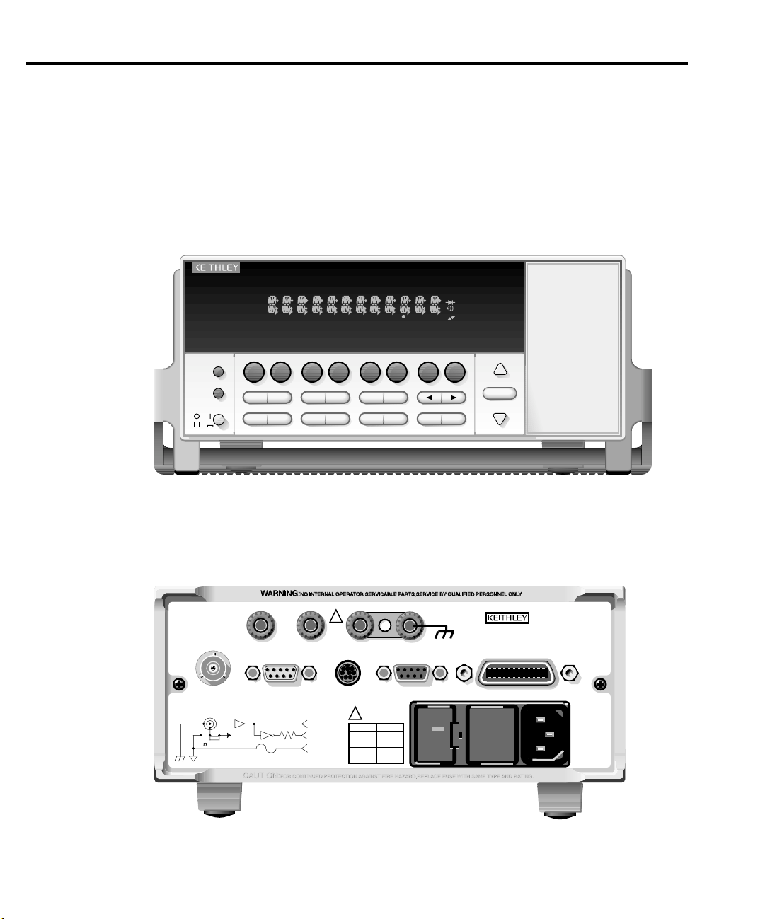
Front and rear panels
The front and rear panels of the Model 6514 are shown in Figures 1 and 2. The use of the
various instrument controls and connectors will be explained throughout this guide.
Figure 1
Front panel
SHIFT
LOCAL
POWER
Figure 2
Rear panel
INPUT 250V PK
INPUT PREAMP
OFF
V, GUARD
(PROGRAMMABLE)
ON
CH1REM
SCAN
STEP CH2 CH3 CH4 CH5 CH6 CH7 CH8 CH9 CH10
TALK
LSTN
SRQ
SHIFT
HOLD TRIG FAST MED SLOW AUTO ERR
TIMER
V
I
%
MX+B
AVG
MEDN
TEST CAL
STORE
RCLL
V-DROP
AUTO-DIS
Ω
VAL
REL LIMIT
SAVE SETUP
DELAY DAMP
REL FILT
Q
CONF-LIM
!
PREAMP OUT
GUARD
(FOLLOWS
INPUT)
250V PK
(INTERNAL)
2V ANALOG
10K
OUTPUT
PREAMP
2V ANALOG
COM
COMMON CHASSIS
TRIGGER LINK
OUT
OUTPUT
!
630mA
315mAT
GPIB
XFBK ZCHK
UNITS
CONF-TRIG
CONF-ARM
LINE RATING
50, 60Hz
60 VA MAX
FUSE LINE
T
100 VAC
(SB)
120 VAC
220 VAC
240 VAC
(SB)
MATH
REAR
4W
BUFFER
STAT
6514 SYSTEM ELECTROMETER
RS-232
ZCOR
GRD
NPLC
RATEDIGIT
EXIT ENTERHALT TRIG
RS232DIGITAL I/O
120
RANGE
AUTO
RANGE
MADE IN
IEEE-488
(CHANGE IEEE ADDRESS
WITH FRONT PANEL MENU)
U.S.A.

Basic connections
Model 6514 Quick Results Guide 3
WARNING
CAUTION
The maximum common-mode input voltage, which is the voltage
between the input (HI or LO) and chassis ground, is 500V peak.
Exceeding this value may create a shock hazard.
Connecting PREAMP OUT, COMMON, or 2V ANALOG OUTPUT to
earth while floating the input may damage the instrument.
Input connector
The rear panel INPUT connector is a 3-lug female triax connector that will mate to a cable
terminated with a male triax connector. As shown in Figure 3, the input connector can be
configured with guard off or guard on. The guarded configuration is used for guarded Volts
and guarded Ohms measurements only. The GRD key toggles guard on and off.
NO T E
Low noise input cables
When making precision measurements, you should always use low noise cables. The
following low noise cables are recommended for use with the Model 6514:
The state of guard (on or off) has no affect on the Amps and
Coulombs functions. The unguarded configuration is always
selected for the Amps and Coulombs functions.
•
Model 237-ALG-2
input connector of Model 6514 and is terminated with alligator clips on the other
end.
•
Model 7078-TRX-x cables
3-slot triax connectors on both ends.
NO T E
— This 2-meter low noise triax cable mates directly to the
— These low noise triax cables are terminated with
As a general rule, always use the shortest possible cable for volts,
amps and ohms measurements.

4 Model 6514 Quick Results Guide
Figure 3
Input connector
Input High
Input Low
INPUT
250V PEAK
Volts, Amps, Ohms & Coulombs
A. Unguarded (GRD off)
Input High
Guard
Chassis
INPUT
250V PEAK
Volts and Ohms only
B. Guarded (GRD on)
Ground
Basic connections to DUT
Unguarded connections
Basic unguarded connections are shown in Figure 4. The DUT is the voltage, current,
resistance, or charge to be measured. For unguarded volts and ohms measurements, the
driven guard (GRD) must be off.
Chassis Ground
COMMON
0.1Ω
Fuse
Input Low
Figure 4
Basic connections for unguarded
measurements
HI
DUT
INPUT
250V PK
NOTE:
LO
For Volts and Ohms,
GRD must be off.

Model 6514 Quick Results Guide 5
Guarded connections
The basic guarded connections for volts and ohms are shown in Figure 5. With guard
(GRD) on, the driven guard is available at the inner shell of the triax connector which is
connected to the metal guard plate. The driven guard is used to eliminate leakage current
and capacitance in high impedance circuits that could corrupt the volts or ohms
measurement.
WARNING
WARNING
The guard voltage is at the same potential as the input. Therefore, hazardous voltage on the input will also be present on the guard plate. To
prevent electric shock, always use a metal safety shield (as shown in
Figure 5) for guarded voltage measurements above 30Vrms (42V
peak). The metal safety shield must be connected to safety earth
ground using #18 AWG or larger wire.
With an open input, up to 250V peak may be present on the guard terminals while in Volts or Ohms. To prevent a safety hazard, enable zero
check whenever the input is open.
Figure 5
Basic connections for guarded measurements
HI
Measure Volts
INPUT
250V PK
COMMON
Chassis
Ground
GRD
LO
Metal Guard Plate
Metal Safety Shield
V
Safety
Earth
Ground
Measure Ohms
INPUT
250V PK
COMMON
NOTE: GRD must be on.
HI
Chassis
Ground
GRD
LO
Metal Guard Plate
Ω
Safety
Earth
Ground
Metal Safety Shield

6 Model 6514 Quick Results Guide
Basic operation
Selecting operating modes
Most front panel keys have a dual operation or function. The nomenclature on a key
indicates its primary or unshifted function or operation. The nomenclature above a key
indicates its shifted function or operation. To select a primary function press the
corresponding key. To select a shifted function, press SHIFT first and then the desired key.
For example, press AVG to select the digital filter. Press SHIFT then MX+B to choose the
mX + b function.
Making volts and ohms measurements
The basic procedure to make volts and ohms measurements is provided in Table 1.
Table 1
Volts and ohms measurement procedure
Procedure Details
1. Enable zero check. Press ZCHK to enable zero check before making
2. Select function. Press V to measure voltage.
3. Enable or disable guard. Use the GRD key to select depending on guarded
4. Perform zero correct (volts only). Press ZCOR to zero correct 6514 for maximum
5. Select range. Use RANGE 5 and 6 keys to manually
6. Connect DUT to 6514 input. See Figure 4 (unguarded) or Figure 5 (guarded).
7. Disable zero check. Press ZCHK to disable zero check in order to
8. Take readings from display. Observe the volts or ohms reading on the front
connection changes or selecting function.
Press Ω to measure ohms.
or unguarded connections.
volts accuracy.
select range. Or press AUTO RANGE (AUTO
annunciator on) to enable auto range.
make measurements.
panel display.

Making amps measurements
The basic procedure to make amps measurements is provided in Table 2.
Table 2
Amps measurement procedure
Procedure Details
1. Enable zero check.
2. Select amps function. Press I to measure current.
3. Perform zero correct. Press ZCOR to zero correct 6514 for maximum
4. Select range. Use RANGE 5 and 6 keys to manually
5. Connect DUT to 6514 input. See Figure 4.
6. Disable zero check. Press ZCHK to disable zero check in order to
7. Take readings from display. Observe the amps reading on the front panel
Model 6514 Quick Results Guide 7
Press ZCHK to enable zero check before making
connection changes or selecting function.
accuracy.
select range. Or press AUTO RANGE (AUTO
annunciator on) to enable auto range.
make measurements.
display.
Making charge measurements
The basic procedure to make charge measurements is provided in Table 3.
Table 3
Charge measurement procedure
Procedure Details
1. Enable zero check. Press ZCHK to enable zero check before making
2. Select coulombs function. Press Q to measure charge in coulombs.
3. Select range. Use RANGE 5 and 6 keys to manually
4. Connect input cable to 6514. Do not connect DUT to cable (open input).
5. Disable zero check, enable relative. Press ZCHK to disable zero check, then press
6. Connect DUT to 6514 input. See Figure 4.
7. Take readings from display. Observe the coulombs reading on the front panel
connection changes or selecting function.
select range. Or press AUTO RANGE (AUTO
annunciator on) to enable auto range.
REL.
display.

8 Model 6514 Quick Results Guide
Measurement considerations
For sensitive measurements, keep these points in mind to maximize measurement
accuracy:
• Use only low noise triax cable for input connections.
• Use zero correct with zero check enabled to null internal offsets.
• Keep the Model 6514 and test circuit away from electrical noise sources, and shield
if necessary.
Remote command programming
Data string
The :READ? command is typically used to trigger a reading and request the data string.
The data string is sent to the computer when the Model 6514 is addressed to talk. The data
string can be made of up to three elements separated by commas. The first element is the
voltage, current, resistance, or charge reading, the second is the timestamp, and the third is
status. A three-element data string is the default condition. See Section 16,
subsystem,
format.
of the Model 6514 Instruction Manual for details on all aspects of the data
FORMat
Command characters
Commands characters enclosed in brackets [] are optional and are not required. Do not
include the brackets when programming the Model 6514. Portions of commands in uppercase indicate the command short form; lower-case command characters are optional and
need not be included in the command string. See Section 12 of the Model 6514 Instruction
Manual for more information on programming syntax.

Model 6514 Quick Results Guide 9
SCPI commands
SCPI commands to make basic measurements are provided in Table 4.
Table 4
SCPI commands for basic measurements
Command* Description
[:SENSe[1]]:FUNCtion <name> Select function: ‘VOLTage’, ‘CURRent’,
‘RESistance’, or ‘CHARge’.
[:SENSe[1]]:XXX:RANGe <n> Select measure range; <n> = range.
[:SENSe[1]]:XXX:RANGe:AUTO <b> Enable/disable auto range; (ON or OFF).
[:SENSe[1]]:VOLTage:GUARd <b> Enable (ON) or disable (OFF) guard for volts.
[:SENSe[1]]:RESistance:GUARd <b> Enable (ON) or disable (OFF) guard for ohms.
:SYSTem:ZCHeck <b> Enable (ON) or disable (OFF) zero check.
:READ? Trigger and acquire one data string.
* XXX = VOLTage, CURRent, RESistance, or CHARge, depending on function.
Programming examples
Volts measurement example
— Table 5 shows a typical command sequence to measure
volts on the 20V range with guard enabled.
Amps measurement example
— Table 6 shows a typical command sequence to measure
amps using auto range.
Table 5
Command sequence for volts measurement example
Command* Comments
*RST Restore GPIB defaults.
SENS:FUNC ‘VOLT’ Select volts measurement function.
SENS:VOLT:RANG 20 Select 20V range.
SENS:VOLT:GUAR ON Enable guard mode.
SYST:ZCH OFF Disable zero check.
READ? Trigger and acquire one voltage reading.
*Model 6514 must be addressed to talk after sending :READ? to trigger and acquire data.
10 Model 6514 Quick Results Guide
Table 6
Command sequence for amps measurement example
Command* Comments
*RST Restore GPIB defaults.
SENS:FUNC ‘CURR’ Select amps measurement function.
SENS:CURR:RANG:AUTO ON Enable auto range.
SYST:ZCH OFF Disable zero check.
READ? Trigger and acquire one current reading.
*Model 6514 must be addressed to talk after sending :READ? to trigger and acquire data.
Settings to optimize performance
Range
To achieve best accuracy, the Model 6514 should be on the lowest possible measurement
range. In most situations, auto range can be used to automatically select the best range.
Auto range is controlled (enabled/disabled) by the AUTO range key (AUTO annunciator
indicates auto range is enabled).
The RANGE 5 and 6 keys are used for manual range selection. Note that pressing
either of these keys disables auto range.
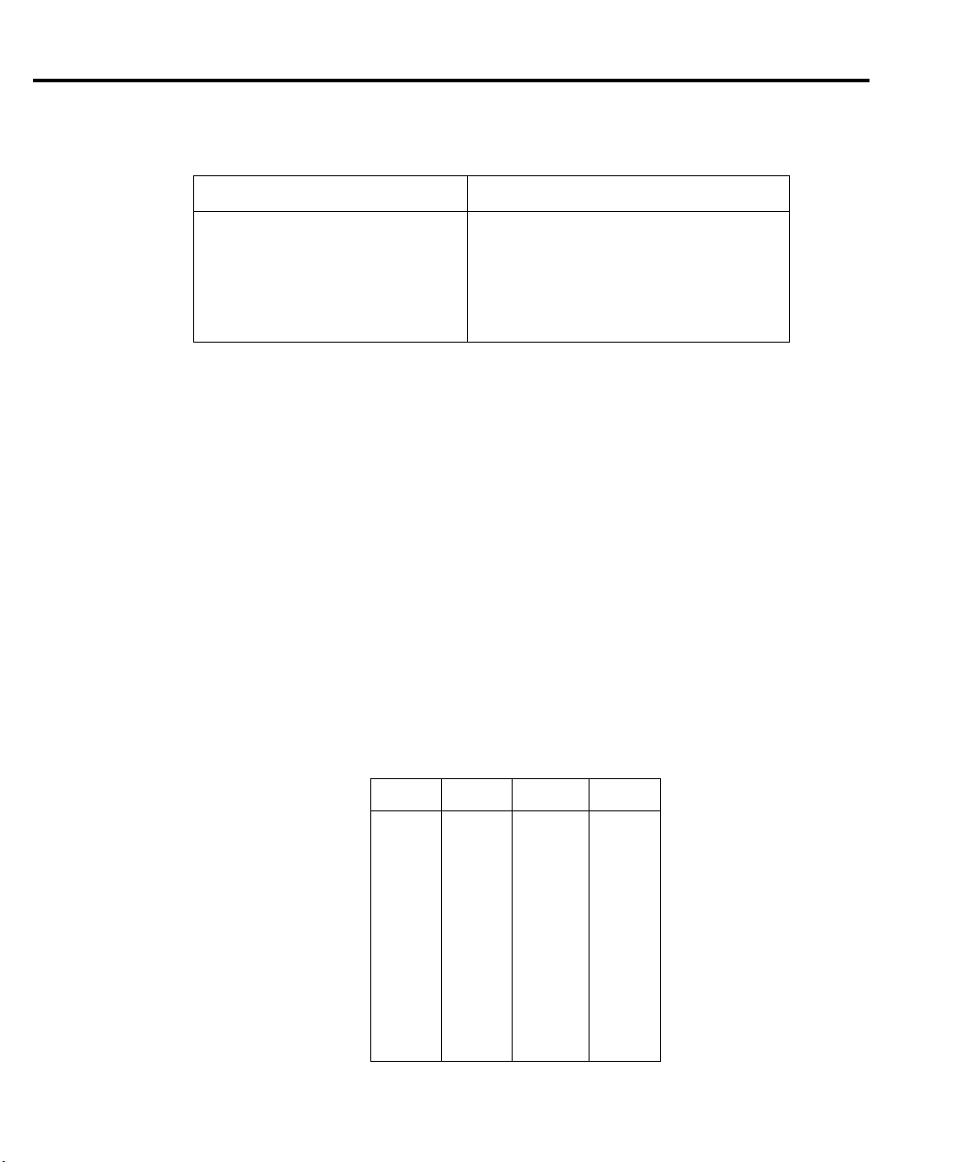
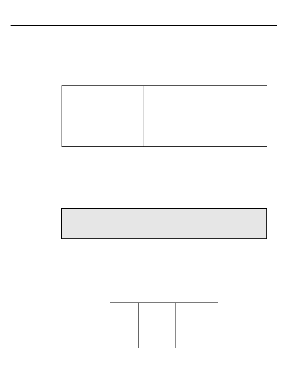
The ranges for each measurement function are listed in Table 7. The range setting (fixed or
AUTO) is remembered by each function. The full scale readings for every measurement
range are 5% over range.
Table 7
Measurement ranges
V I
2V 20pA 2k
20V 200pA 20k
200V 2nA 200k
20nA 2M
200nA 20M
2µA
20µA 2G
200µA 20G
2mA
20mA
Ω
Ω
Ω
Ω
200M
Ω
200G
Q
20nC
200nC
2µC
Ω
20µC
Ω
Ω
Ω
Ω

Rate
Model 6514 Quick Results Guide 11
The RATE key selects the integration time of the A/D converter. This is the period of time
the input signal is measured. The integration time affects the amount of reading noise, as
well as the ultimate reading rate of the instrument. The integration time is specified in
parameters based on a number of power line cycles (NPLC), where 1 PLC for 60Hz is
16.67msec (1/60) and 1 PLC for 50Hz (and 400Hz) is 20msec (1/50).
The rate setting is global for all measurement functions. Therefore, it does not matter what
function is presently selected when you set rate. There are two ways to set rate. You can
select slow, medium, or fast by using the RATE key, or you can set the number of power
cycles from the NPLC menu that is accessed by pressing SHIFT and then NPLC.
To change the rate setting, press (and release) the RATE key until the desired rate
annunciator (SLOW, MED, or FAST) is displayed:
• SLOW — Selects the slowest front panel integration time (6 PLC for 60 Hz or
5 PLC for 50 Hz) and sets display resolution to 5½-digit resolution. The SLOW
rate provides better noise performance at the expense of speed.
• MED — Selects the medium integration time (1 PLC) and sets display resolution
to 5½-digit resolution. Select the MED rate when a compromise between noise
performance and speed is acceptable.
• FAST — Selects the fastest front panel integration time (0.1 PLC) and sets display
resolution to 4½-digit resolution. Select the FAST rate if speed is of primary
importance (at the expense of increased reading noise).
Digits
Filter
The DIGIT key sets display resolution for Model 6514. Display resolution can be set from
3½ to 6½ digits. This single global setting affects display resolution for all measurement
functions. To set display resolution, press (and release) the DIGIT key until the desired
number of digits is displayed.
NO TE
Filtering stabilizes noisy measurements caused by noisy input signals. The Model 6514
uses two types of filters: median and digital. Note that both the median and digital filters
can be in effect at the same time.
Changing the integration rate changes display resolution, but changing
display resolution does not change the rate setting (see RATE for
details).

12 Model 6514 Quick Results Guide
With both filters enabled, the median filter operation is performed first. After the median
filter yields a reading, it is sent to the stack of the digital filter. Therefore, a filtered reading
will not be displayed until both filter operations are completed.
The settings for the filter are global. Therefore, the filter configuration applies to all four
measurement functions. The MEDN key is used to configure and control the median filter,
and the AVG key is used to configure and control the digital filter. When either the median
or digital filter is enabled, the FILT annunciator is on.
Median filter
The median filter is used to determine the “middle-most” reading from a group of readings
that are arranged according to size. The number of sample readings used for the median
calculation is determined by the selected rank (1 to 5) as follows:
Sample readings = (2 × R) + 1
where: R is the selected rank (1 to 5)
To configure the median filter, press the MEDN key to display the present filter rank. Then
use the RANGE keys to display the desired rank (1 to 5), and press ENTER.
Digital filter
REL key
The digital filter type can be either moving or repeating. With the moving filter, each time
a reading conversion occurs, the readings in the stack are averaged to yield a single filtered
reading. The stack type is first-in, first-out. After the stack fills, the newest reading
conversion replaces the oldest. Note that the instrument does not wait for the stack to fill
before releasing readings. With the repeating filter, the unit takes a selected number of
reading conversions, averages them, and yields a reading. It then flushes its stack and
starts over.
To configure the digital filter, press the AVG key, (the set the number of readings to
average (1-100)). Choose the repeat or moving average type, then press ENTER.
The REL key nulls an offset or subtracts a baseline value from future readings. Note that
the rel value is the same for each measurement range. For example, a rel value of 1V on
the 2V range is also 1V on the 20V and 200V ranges.
Perform the following steps to set a rel value:
1. Display the reading you want as the rel value. This could be a zero offset reading
that you want to null out, or it could be an applied level that you want to use as a
baseline.
2. Press REL. The REL annunciator turns on, and subsequent readings will be the difference between the actual input and the rel value.
3. To disable REL, press the REL key a second time. The REL annunciator turns off.

Remote command programming
The SCPI commands for speed, digits, filter, and rel are listed in Table 8. The commands
for ranging are listed in Table 4.
Table 8
SCPI commands: rate, digits, filter, and rel
Command Description
Rate commands:
[:SENSe[1]]:VOLTage:NPLCycles <n> Set voltage rate in PLCs: 0.01 to 10.
[:SENSe[1]]:CURRent:NPLCycles <n> Set current rate in PLCs: 0.01 to 10.
[:SENSe[1]]:RESistance:NPLCycles <n> Set resistance rate in PLCs: 0.01 to 10.
[:SENSe[1]]:CHARge:NPLCycles <n> Set charge rate in PLCs: 0.01 to 10.
Digits command:
:DISPlay:DIGits <n> Set display resolution: 4 to 7.
Median filter commands:
[:SENSe[1]]:MEDian:RANK <n> Set median filter rank: 1 to 5.
[:SENSe[1]]:MEDian[:STATe] <b> Enable or disable median filter.
Model 6514 Quick Results Guide 13
Digital filter commands:
[:SENSe[1]]:AVERage:TCONtrol <name> Select filter control: MOVing or REPeat.
[:SENSe[1]]:AVERage:COUNt <n> Set filter count: 1 to 100.
[:SENSe[1]]:AVERage[:STATe] <b> Enable or disable digital filter.
Rel command:*
:CALCulate2:NULL:STATe <b> Enable/disable rel.
* Does not include commands to set and acquire rel values. See Section 7 of Model 6514 Instruction Manual.

14 Model 6514 Quick Results Guide
Features to enhance DUT testing
Buffer
The Model 6514 has a buffer to store from one to 2500 readings. It also stores overflow
readings and includes a timestamp. In addition, recalled data includes statistical
information (minimum, maximum, peak-to-peak, average, and standard deviation). The
buffer fills with the specified number of readings and stops. Readings are placed in the
buffer after any math operations are performed. Math operations include mX+b, percent,
or limits.
Storing readings
To store readings, press the STORE, key in the number of readings to store, and press
ENTER. The star (*) annunciator indicates that the buffer is enabled. If in the immediate
trigger mode, the storage process will start immediately. If in the external trigger mode,
each input trigger (or press of TRIG key) will store a reading. The star (*) indicator will go
off when the buffer is full.
Recalling readings
To recall readings, press the RCLL key. The message “RDG NO 1” is displayed. The arrow
annunciator (↔) also turns on to indicate additional data is available for viewing. Use the
RANGE and cursor keys to navigate through the reading numbers, reading values,
timestamps, and buffer statistics. To return to the normal display, press EXIT.
Buffer statistics
• MIN and MAX provides the minimum and maximum readings stored in the buffer.
It also indicates the buffer location of these readings.
• The PK-PK (peak-to-peak) reading is the absolute value of the difference between
the MAX and MIN readings. It is calculated as follows:
Peak-to-Peak = |MAX - MIN|
• Average is the mean of the buffer readings. Mean is calculated as follows:
n
X
∑
i
i1=
-----------------=
y
n
where: Xi is a stored reading.
n is the number of stored readings.
Model 6514 Quick Results Guide 15
• The STD DEV value is the standard deviation of the buffered readings. The equa-
tion used to calculate the standard deviation is:
n
2
X
∑
y =
i
i1=
--------------------------------------------------------------
n
1
---X
–
n
i1=
n-1
∑
2
i
where: Xi is a stored reading.
n is the number of stored readings.
NO T E The Model 6514 uses IEEE-754 floating point format for math
calculations.
Remote buffer programming
SCPI commands
SCPI commands to configure and control the buffer and buffer statistics are listed in Table 9.
Table 9
SCPI commands: buffer
Command Description
:TRACe:CLEar Clear readings from buffer.
:TRACe FREE? Query bytes available and bytes in use.
:TRACe:POINts <n> Specify number of readings to store: 1 to 2500.
:TRACe:FEED <name> Select source of readings: SENSe[1], CALCu-
late[1], or CALCulate2.
:TRACe:FEED:CONTrol <name> Select buffer control mode: NEVer or NEXT.
:TRACe:TSTamp:FORMat <name> Select timestamp format: ABSolute or DELta.
:TRACe:DATA? Read all readings in buffer.
:FORMat:ELEMents <list> Specify buffer data elements: READing, TIME,
and STATus.
:CALCulate3:FORMat <name>
Select buffer statistic: MINimum, MAXimum,
MEAN, SDEViation, or PKPK.
:CALCulate3:DATA? Read selected buffer statistic.
16 Model 6514 Quick Results Guide
Programming example
Table 10 shows a typical command sequence to store and recall readings and mean buffer
statistics.
Table 10
Command sequence for buffer example
Command* Comments
:TRAC:POIN 20 Set buffer size to 20,
:TRAC:FEED SENS Set to store raw readings.
:TRAC:FEED:CONT NEXT Start storing readings.
:TRAC:DATA? Request all stored readings.*
:CALC3:FORM MEAN Select mean calculation.
:CALC3:DATA? Perform calculation and request result.*
*Model 6514 must be addressed to talk after sending :TRAC:DATA? and :CALC3:DATA? to acquire data.
Limit testing
Limit operations set and control the values that determine the pass/fail status of
subsequent measurements. The limit test is performed on the result of an enabled Rel,
mX+b, or Percent operation.
NO T E This guide contains basic information on limit testing. See
Section 10 of the Model 6514 Instruction Manual for complete
details on limit testing, including information on binning and using
a component handler.
There are two sets of limit tests, Limit 1 and Limit 2. Both limits use high and low values.
Factory defaults for both limit tests are +1 (high) and -1 (low). Table 11 lists limit test
display messages depending on pass/fail status.
Table 11
Limit test display messages
Display
Message
:OK Pass Pass
:L1 Fail Not Performed
:L2 Pass Fail
Limit 1
Test Result
Limit 2
Test Result

Model 6514 Quick Results Guide 17
Configuring limit tests
Press SHIFT then CONF-LIM, then select LIMIT 1 or LIMIT 2. Use CONTROL to
enable the test, then enter your HILIM and LOLIM values (-9.999999T to +9.999999T).
(Place the cursor on the + or - keys to change polarity or the desired range symbol to
change range.)
Once limit tests are configured, use the LIMIT key to start and stop the limit test. Results
are displayed as summarized in Table 11.
Remote limits programming
SCPI commands
Basic SCPI commands for basic limit testing are listed in Table 12. See Section 10 of the
Model 6514 Instruction Manual for additional limit test commands.
Table 12
SCPI commands: basic limit testing
Command Description
:CALCulate2:LIMit:STATe <b> Enable/disable Limit 1 test: <b> = ON or OFF.
:CALCulate2:LIMit:LOWer <n> Set lower limit for Limit 1: <n> = limit:
-9.99999e20 to 9.99999e20.
:CALCulate2:LIMit:UPPer <n> Set upper limit for Limit 1: <n> = limit;
-9.99999e20 to 9.99999e20.
:CALCulate2:LIMit:FAIL? Query Limit 1 test result (0 = pass, 1 = fail).
:CALCulate2:LIMit2:STATe <b> Enable/disable Limit 2 test: <b> = ON or OFF.
:CALCulate2:LIMit2:LOWer <n> Set lower limit for Limit 2: <n> = limit:
-9.99999e20 to 9.99999e20.
:CALCulate2:LIMit2:UPPer <n> Set upper limit for Limit 2: <n> = limit:
-9.99999e20 to 9.99999e20.
:CALCulate2:LIMit2:FAIL? Query Limit 2 test result (0 = pass, 1 = fail).
Programming example
The programming example in Table 12 tests limits on a voltage. Limit 1 values are ±1, and
Limit 2 values are ±0.1.

18 Model 6514 Quick Results Guide
Table 13
Command sequence for limit test example
Command* Comments
*RST Restore GPIB defaults.
:CALC2:LIM:LOW -1 Set Limit 1 lower limit to -1.
:CALC2:LIM:UPP 1 Set Limit 1upper limit to 1.
:CALC2:LIM:STAT ON Enable Limit 1 test.
:CALC2:LIM2:LOW -0.1 Set Limit 2 lower limit to -0.1.
:CALC2:LIM2:UPP 0.1 Set Limit 2 upper limit to 0.1.
:CALC2:LIM2:STAT ON Enable Limit 2 test.
:READ? Trigger and request a reading.*
:CALC2:LIM:FAIL? Request Limit 1 test result.*
:CALC2:LIM2:FAIL? Request Limit 2 test result.*
*Model 6514 must be addressed to talk after sending :READ?, :CALC2:LIM:FAIL? and
:CALC2:LIM2:FAIL? to acquire test result.
Math operations
Model 6514 math operations include mX + b and percent.
mX+b
This math operation manipulates normal display readings (X) mathematically according
to the following calculation:
Y = mX+b
where: X is the normal display reading
m and b are user-entered constants for scale factor and offset
Y is the displayed result
To configure and enable mX + b, press SHIFT and then MX+B to display the present scale
factor. Enter the desired M, B, and UNITS values at the prompts, and press ENTER. The
MATH annunciator will turn on to indicate that mX+b is enabled. Press SHIFT then
MX+B again to disable the function. The MATH annunciator will turn off.
Percent (%)
This math function determines percent deviation from a specified reference value. The
percent calculation is performed as follows:
Percent = –––––––––––––––– × 100%
Reference
where: Input is the normal display reading.
Input – Reference
Reference is the user entered constant.
Percent is the displayed result.

Model 6514 Quick Results Guide 19
To configure and enable the percent function, press SHIFT then %. Enter the desired
reference value, then press ENTER. The MATH annunciator will turn on to indicate that
percent is enabled. Press SHIFT then % again to disable the function. The MATH
annunciator will turn off.
Remote mX+b and percent programming
SCPI commands
Table 14 summarizes commands used for mX+b and percent.
Table 14
SCPI commands; mX+b and percent
Command Description
:CALCulate:FORMat <name> Select calculation; MXB or PERCent.
:CALCulate:KMATh:MMFactor <n> Specify scale factor (M) for mX+b: -9.99999e20 to
9.99999e20.
:CALCulate:KMATh:MBFactor <n> Specify offset (B) for mX+b: -9.99999e20 to 9.99999e20.
:CALCulate:KMATh:MUNits <name> Specify units for mX+b (one or two characters enclosed in
single or double quotes).
:CALCulate:KMATh:PERcent <n> Specify reference value for Percent: -9.99999e20 to
9.99999e20.
:CALCulate:KMATh:PERcent:ACQuir Use input signal as reference value.
:CALCulate:STATe <b> Enable or disable the selected calculation.
:CALCulate:DATA? Query calculation result.
Programming example
The command sequence in Table 15 programs the mX+b function and requests the result.
Table 15
Command sequence for mX+b measurement example
Command* Comments
:CALC:FORM MXB Select mX+b function.
:CALC:KMAT:MMF 2 M = 2.
:CALC:KMAT:MBF 0.5 B = 0.5
:CALC:STAT ON Enable mX+b.
:INIT Trigger reading and calculation.
:CALC:DATA? Request mX+b result.
*Model 6514 must be addressed to talk after sending :CALC:DATA? to acquire reading.

Index
B
Buffer statistics 14
M
mX+b 18
P
Percent (%) 18
R
Ratio programming example 19
REL Key 12

Specifications are subject to change without notice.
All Keithley trademarks and trade names are the property of Keithley Instruments, Inc.
All other trademarks and trade names are the property of their respective companies.
Keithley Instruments, Inc. 28775 Aurora Road • Cleveland, Ohio 44139 • 440-248-0400 • Fax: 440-248-6168
1-888-KEITHLEY (534-8453) • www.keithley.com
Sales Offices: BELGIUM: Bergensesteenweg 709 • B-1600 Sint-Pieters-Leeuw • 02-363 00 40 • Fax: 02-363 00 64
CHINA: Yuan Chen Xin Building, Room 705 • 12 Yumin Road, Dewai, Madian • Beijing 100029 • 8610-82251886 • Fax: 8610-82251892
FINLAND: Halsuantie 2 • 00420 Helsinki, Finland • 09-53 06 65 60 • Fax: 09-53 06 65 65
FRANCE: 3, allée des Garays • 91127 Palaiseau Cédex • 01-64 53 20 20 • Fax: 01-60 11 77 26
GERMANY: Landsberger Strasse 65 • 82110 Germering • 089-84 93 07-40 • Fax: 089-84 93 07-34
GREAT BRITAIN: Unit 2 Commerce Park, Brunel Road • Theale, Berkshire RG7 4AB • 0118 -929 75 00 • Fax: 0118- 929 75 19
INDIA: 1/5, Eagles Street • Langford Town • Bangalore 560 025 • 080 212 80-27 • Fax: 080 212 80 05
ITALY: Viale San Gimignano, 38 • 20146 Milano • 02-48 39 16 01 • Fax: 02-48 30 22 74
JAPAN: New Pier Takeshiba North Tower 13F • 11-1, Kaigan 1-chome • Minato-ku, Tokyo 105-0022 • 81-3-5733-7555 • Fax: 81-3-5733-7556
KOREA: 2FL., URI Building • 2-14 Yangjae-Dong • Seocho-Gu, Seoul 137-888 • 82-2-574-7778 • Fax: 82-2-574-7838
NETHERLANDS: Postbus 559 • 4200 AN Gorinchem • 0183-63 53 33 • Fax: 0183-63 08 21
SWEDEN: c/o Regus Business Centre • Frosundaviks Allé 15, 4tr • 16970 Solna • 08-50 90 46 00 • Fax: 08-655 26 10
TAIWAN: 13F-3, NO. 6, Lane 99, Pu-Ding Road, Hsinchu, Taiwan, ROC. • 886-3-572-9077• Fax: 886-3-572-9031
© Copyright 2003 Keithley Instruments, Inc.
Printed in the U.S.A.
5/03
 Loading...