

Page 1

Model 6430 Sub-Femtoamp Remote SourceMeter
Instruction Manual
A GREATER MEASURE OF CONFIDENCE
Page 2

WARRANTY
Keithley Instruments, Inc. warrants this product to be free from defects in material and workmanship for a
period of 1 year from date of shipment.
Keithley Instruments, Inc. warrants the following items for 90 days from the date of shipment: probes, cables,
rechargeable batteries, diskettes, and documentation.
During the warranty period, we will, at our option, either repair or replace any product that proves to be
defective.
To exercise this warranty, write or call your local Keithley representative, or contact Keithley headquarters in
Cleveland, Ohio. You will be given prompt assistance and return instructions. Send the product, transportation
prepaid, to the indicated service facility. Repairs will be made and the product returned, transportation prepaid.
Repaired or replaced products are warranted for the balance of the original warranty period, or at least 90 days.
LIMITATION OF WARRANTY
This warranty does not apply to defects resulting from product modification without Keithley’s express written
consent, or misuse of any product or part. This warranty also does not apply to fuses, software, nonrechargeable batteries, damage from battery leakage, or problems arising from normal wear or failure to follow
instructions.
THIS WARRANTY IS IN LIEU OF ALL OTHER WARRANTIES, EXPRESSED OR IMPLIED, INCLUDING ANY IMPLIED WARRANTY OF MERCHANTABILITY OR FITNESS FOR A PARTICULAR USE.
THE REMEDIES PROVIDED HEREIN ARE BUYER’S SOLE AND EXCLUSIVE REMEDIES.
NEITHER KEITHLEY INSTRUMENTS, INC. NOR ANY OF ITS EMPLOYEES SHALL BE LIABLE FOR
ANY DIRECT, INDIRECT, SPECIAL, INCIDENTAL OR CONSEQUENTIAL DAMAGES ARISING OUT OF
THE USE OF ITS INSTRUMENTS AND SOFTWARE EVEN IF KEITHLEY INSTRUMENTS, INC., HAS
BEEN ADVISED IN ADVANCE OF THE POSSIBILITY OF SUCH DAMAGES. SUCH EXCLUDED DAMAGES SHALL INCLUDE, BUT ARE NOT LIMITED TO: COSTS OF REMOVAL AND INSTALLATION,
LOSSES SUSTAINED AS THE RESULT OF INJURY T O ANY PERSON, OR DAMAGE T O PROPERTY.
Keithley Instruments, Inc. • 28775 Aurora Road • Cleveland, OH 44139 • 440-248-0400 • Fax: 440-248-6168 • http://www.keithley.com
BELGIUM: Keithley Instruments B.V. Bergensesteenweg 709 • B-1600 Sint-Pieters-Leeuw • 02/363 00 40 • Fax: 02/363 00 64
CHINA: Keithley Instruments China Y uan Chen Xin Building, Room 705 • 12 Yumin Road, Dewai, Madian • Beijing 100029 • 8610-62022886 • Fax: 8610-62022892
FRANCE: Keithley Instruments Sarl 3, allée des Garays • 91127 Palaiseau Cedex • 01-64 53 20 20 • Fax: 01-60 11 77 26
GERMANY: Keithley Instruments GmbH Landsberger Strasse 65 • 82110 Germering • 089/84 93 07-40 • Fax: 089/84 93 07-34
GREAT BRITAIN: Keithley Instruments Ltd Unit 2 Commerce Park, Brunel Road • Theale • Reading • Berkshire RG7 4AB • 0118 929 7500 • Fax: 0118 929 7519
INDIA: Keithley Instruments GmbH Flat 2B, WILOCRISSA • 14, Rest House Crescent • Bangalore 560 001 • 91-80-509-1320/21 • Fax: 91-80-509-1322
ITALY: Keithley Instruments s.r.l. Viale S. Gimignano, 38 • 20146 Milano • 02-48 39 16 01 • Fax: 02-48 30 22 74
NETHERLANDS: Keithley Instruments B.V. Postbus 559 • 4200 AN Gorinchem • 0183-635333 • Fax: 0183-630821
SWITZERLAND: Keithley Instruments SA Kriesbachstrasse 4 • 8600 Dübendorf • 01-821 94 44 • Fax: 01-820 30 81
TAIWAN: Keithley Instruments Taiwan 1 Fl. 85 Po Ai Street • Hsinchu, Taiwan, R.O.C. • 886-3572-9077 • Fax: 886-3572-903
4/01
Page 3

Model 6430 Sub-Femtoamp Remote SourceMeter
Instruction Manual
©1999, Keithley Instruments, Inc.
All rights reserved.
Cleveland, Ohio, U.S.A.
Fourth Printing, June 2001
Document Number: 6430-901-01 Rev. D
Page 4

Manual Print History
The print history shown below lists the printing dates of all Revisions and Addenda
created for this manual. The Revision Level letter increases alphabetically as the manual
undergoes subsequent updates. Addenda, which are released between Revisions, contain
important change information that the user should incorporate immediately into the
manual. Addenda are numbered sequentially. When a new Revision is created, all Addenda
associated with the previous Revision of the manual are incorporated into the new Revision
of the manual. Each new Revision includes a revised copy of this print history page.
Revision A (Document Number 6430-901-01) ................................................................ May 1999
Addendum A (Document Number 6430-901-02) ............................................................ June 1999
Revision B (Document Number 6430-901-01) ...................................................... September 1999
Addendum B (Document Number 6430-901-02) .................................................. November 1999
Revision C (Document Number 6430-901-01) ........................................................... January 2000
Revision D (Document Number 6430-901-01) ............................................................... June 2001
All Keithley product names are trademarks or registered trademarks of Keithley Instruments, Inc.
Other brand names are trademarks or registered trademarks of their respective holders.
Page 5

Safety Precautions
The following safety precautions should be observed before using this product and any associated instrumentation. Although some instruments and accessories would normally be used with non-hazardous
voltages, there are situations where hazardous conditions may be present.
This product is intended for use by qualified personnel who recognize shock hazards and are familiar
with the safety precautions required to avoid possible injury. Read the operating information carefully
before using the product.
The types of product users are:
Responsible body is the individual or group responsible for the use and maintenance of equipment, for
ensuring that the equipment is operated within its specifications and operating limits, and for ensuring
that operators are adequately trained.
Operators use the product for its intended function. They must be trained in electrical safety procedures
and proper use of the instrument. They must be protected from electric shock and contact with hazardous
live circuits.
Maintenance personnel perform routine procedures on the product to keep it operating, for example,
setting the line voltage or replacing consumable materials. Maintenance procedures are described in the
manual. The procedures explicitly state if the operator may perform them. Otherwise, they should be
performed only by service personnel.
Service personnel are trained to w ork on li v e circuits, and perform safe installations and repairs of products. Only properly trained service personnel may perform installation and service procedures.
Keithley products are designed for use with electrical signals that are rated Installation Category I and
Installation Category II, as described in the International Electrotechnical Commission (IEC) Standard
IEC 60664. Most measurement, control, and data I/O signals are Installation Category I and must not
be directly connected to mains voltage or to voltage sources with high transient over-voltages. Installation Category II connections require protection for high transient o v er -v oltages often associated with local AC mains connections. The user should assume all measurement, control, and data I/O connections
are for connection to Category I sources unless otherwise marked or described in the Manual.
Exercise extreme caution when a shock hazard is present. Lethal voltage may be present on cable connector jacks or test fixtures. The American National Standards Institute (ANSI) states that a shock hazard exists when voltage levels greater than 30V RMS, 42.4V peak, or 60VDC are present. A good safety
practice is to expect that hazardous voltage is present in any unknown circuit before measuring.
Users of this product must be protected from electric shock at all times. The responsible body must ensure that users are prevented access and/or insulated from every connection point. In some cases, connections must be exposed to potential human contact. Product users in these circumstances must be
trained to protect themselves from the risk of electric shock. If the circuit is capable of operating at or
above 1000 volts, no conductive part of the circuit may be exposed.
Do not connect switching cards directly to unlimited power circuits. They are intended to be used with
impedance limited sources. NEVER connect switching cards directly to AC mains. When connecting
sources to switching cards, install protective devices to limit fault current and voltage to the card.
Before operating an instrument, make sure the line cord is connected to a properly grounded power receptacle. Inspect the connecting cables, test leads, and jumpers for possible wear, cracks, or breaks before each use.
When installing equipment where access to the main power cord is restricted, such as rack mounting, a
separate main input power disconnect device must be provided, in close proximity to the equipment and
within easy reach of the operator.
Page 6
For maximum safety, do not touch the product, test cables, or any other instruments while power is applied to
the circuit under test. AL WAYS remove power from the entire test system and discharge any capacitors before:
connecting or disconnecting cables or jumpers, installing or removing switching cards, or making internal
changes, such as installing or removing jumpers.
Do not touch any object that could provide a current path to the common side of the circuit under test or power
line (earth) ground. Always make measurements with dry hands while standing on a dry, insulated surface capable of withstanding the voltage being measured.
The instrument and accessories must be used in accordance with its specifications and operating instructions
or the safety of the equipment may be impaired.
Do not exceed the maximum signal levels of the instruments and accessories, as defined in the specifications
and operating information, and as shown on the instrument or test fixture panels, or switching card.
When fuses are used in a product, replace with same type and rating for continued protection against fire hazard.
Chassis connections must only be used as shield connections for measuring circuits, NOT as safety earth
ground connections.
If you are using a test fixture, keep the lid closed while power is applied to the device under test. Safe operation
requires the use of a lid interlock.
If a scre w is present, connect it to safety earth ground using the wire recommended in the user documentation.
!
The symbol on an instrument indicates that the user should refer to the operating instructions located in
the manual.
The symbol on an instrument shows that it can source or measure 1000 volts or more, including the combined effect of normal and common mode voltages. Use standard safety precautions to a v oid personal contact
with these voltages.
The WARNING heading in a manual explains dangers that might result in personal injury or death. Always
read the associated information very carefully before performing the indicated procedure.
The CAUTION heading in a manual explains hazards that could damage the instrument. Such damage may
invalidate the warranty .
Instrumentation and accessories shall not be connected to humans.
Before performing any maintenance, disconnect the line cord and all test cables.
To maintain protection from electric shock and fire, replacement components in mains circuits, including the
power transformer, test leads, and input jacks, must be purchased from Keithley Instruments. Standard fuses,
with applicable national safety approvals, may be used if the rating and type are the same. Other components
that are not safety related may be purchased from other suppliers as long as they are equivalent to the original
component. (Note that selected parts should be purchased only through Keithley Instruments to maintain accuracy and functionality of the product.) If you are unsure about the applicability of a replacement component,
call a Keithley Instruments office for information.
To clean an instrument, use a damp cloth or mild, water based cleaner. Clean the exterior of the instrument
only. Do not apply cleaner directly to the instrument or allow liquids to enter or spill on the instrument. Products that consist of a circuit board with no case or chassis (e.g., data acquisition board for installation into a
computer) should never require cleaning if handled according to instructions. If the board becomes contaminated and operation is affected, the board should be returned to the factory for proper cleaning/servicing.
Rev . 2/01
Page 7

Table of Contents
1 Getting Started
General information ................................................................... 1-2
Warranty information .......................................................... 1-2
Contact information ............................................................ 1-2
Manual addenda .................................................................. 1-2
Safety symbols and terms ................................................... 1-2
Inspection ............................................................................ 1-3
Options and accessories ...................................................... 1-3
Product overview ........................................................................ 1-6
Mainframe and Remote PreAmp familiarization ....................... 1-7
Mainframe front panel summary ........................................ 1-7
Mainframe rear panel summary .......................................... 1-9
Remote PreAmp summary ................................................ 1-10
Power-up .................................................................................. 1-12
Line power connection ...................................................... 1-12
Power-up sequence ........................................................... 1-13
System identification ......................................................... 1-13
Line frequency setting ....................................................... 1-13
Fuse replacement .............................................................. 1-14
Display ..................................................................................... 1-15
Display format .................................................................. 1-15
EDIT key ........................................................................... 1-15
TOGGLE key .................................................................... 1-15
Status and error messages ................................................. 1-16
Remote display programming ........................................... 1-16
Front panel tests ................................................................ 1-16
Disabling front panel display ............................................ 1-16
Default settings ......................................................................... 1-17
Saving and restoring user setups ....................................... 1-17
Power-on configuration ..................................................... 1-18
Factory default settings ..................................................... 1-18
Remote setups ................................................................... 1-20
Menus ....................................................................................... 1-21
Main menu ........................................................................ 1-21
Rules to navigate menus ................................................... 1-24
Editing source and compliance values .............................. 1-25
Toggling the source and measure display fields ................ 1-25
Configuration menus ......................................................... 1-26
Page 8

2 Connections
Connection overview .................................................................. 2-2
Connecting Remote PreAmp to the mainframe .................. 2-2
Source-measure terminals ................................................... 2-3
Test fixture interlock ............................................................ 2-5
Connections to DUT ................................................................... 2-6
Sensing methods .................................................................. 2-6
Guarding methods ...................................................................... 2-9
Cable guard ......................................................................... 2-9
Ohms guard ....................................................................... 2-10
Guard selection .................................................................. 2-13
3 Basic Source-Measure Operation
CAUTION .................................................................................. 3-2
Operation overview .................................................................... 3-3
Source-measure capabilities ................................................ 3-3
Compliance limit ................................................................. 3-4
Setting the compliance limit ................................................ 3-5
Basic circuit configuration .................................................. 3-6
Operation considerations ............................................................ 3-6
Warm-up .............................................................................. 3-6
Auto zero ............................................................................. 3-6
NPLC caching ..................................................................... 3-7
V-source protection ............................................................. 3-8
Source delay ........................................................................ 3-9
Basic source-measure procedure .............................................. 3-10
Output control ................................................................... 3-10
Current measurements and capacitive loads ...................... 3-11
Front panel source-measure procedure ............................. 3-12
Remote command source-measure procedure ................... 3-15
Measure only ............................................................................ 3-17
Front panel measure only .................................................. 3-17
Remote command measure only ....................................... 3-18
Sink operation ........................................................................... 3-19
Overview ........................................................................... 3-19
Sink programming example .............................................. 3-19
Page 9

4 Ohms Measurements
Ohms configuration menu .......................................................... 4-2
Ohms measurement methods ..................................................... 4-3
Selecting ohms measurement method ................................. 4-4
Auto ohms measurements ................................................... 4-4
Manual ohms measurements ............................................... 4-5
Ohms sensing ............................................................................. 4-6
Offset-compensated ohms .......................................................... 4-7
Measuring high resistance devices ...................................... 4-7
Enabling/disabling offset-compensated ohms .................... 4-8
Offset-compensated ohms procedure .................................. 4-8
Ohms source readback ............................................................... 4-9
6-wire ohms measurements ........................................................ 4-9
Remote ohms programming ..................................................... 4-10
Remote ohms commands .................................................. 4-10
Ohms programming example ............................................ 4-10
5 Source-Measure Concepts
Compliance limit ........................................................................ 5-2
Types of compliance ........................................................... 5-2
Maximum compliance values ............................................. 5-3
Compliance examples ......................................................... 5-3
Compliance principles ........................................................ 5-4
Determining compliance limit ............................................ 5-4
Overheating protection ............................................................... 5-5
Source-delay-measure cycle ....................................................... 5-6
Sweep waveforms ............................................................... 5-8
Operating boundaries ................................................................. 5-9
Source or sink ..................................................................... 5-9
I -Source operating boundaries ......................................... 5-10
V-Source operating boundaries ......................................... 5-14
Source I measure I and source V measure V .................... 5-18
Basic circuit configurations ...................................................... 5-18
Source I ............................................................................. 5-18
Source V ............................................................................ 5-20
Measure only (V or I) ....................................................... 5-21
Guard ........................................................................................ 5-22
Cable guard ....................................................................... 5-22
Ohms guard ....................................................................... 5-24
Guard sense ....................................................................... 5-24
Data flow .................................................................................. 5-26
Buffer considerations ........................................................ 5-28
Page 10

6 Range, Digits, Speed, and Filters
Range and digits ......................................................................... 6-2
Range ................................................................................... 6-2
Digits ................................................................................... 6-5
Remote range and digits programming ............................... 6-6
Speed .......................................................................................... 6-7
Setting speed ....................................................................... 6-7
Remote speed programming ................................................ 6-8
Filters .......................................................................................... 6-9
Filter stages ......................................................................... 6-9
Auto filter .......................................................................... 6-13
Filter configuration ............................................................ 6-15
Filter control ...................................................................... 6-16
Remote filter programming ............................................... 6-16
7 Relative and Math
Relative ....................................................................................... 7-2
Front panel rel ..................................................................... 7-2
Remote rel programming .................................................... 7-3
Math operations .......................................................................... 7-4
Math functions ..................................................................... 7-4
Front panel math operations ................................................ 7-7
Remote math operations ...................................................... 7-8
User-defined math functions ............................................. 7-10
8 Data Store
Data store overview .................................................................... 8-2
Front panel data store ................................................................. 8-2
Storing readings ................................................................... 8-2
Recalling readings ............................................................... 8-2
Buffer statistics .................................................................... 8-3
Timestamp format ............................................................... 8-4
Timestamp accuracy ............................................................ 8-4
Buffer considerations .......................................................... 8-5
Remote command data store ...................................................... 8-6
Data store commands .......................................................... 8-6
Data store programming example ....................................... 8-7
Page 11

9 Sweep Operation
Sweep types ................................................................................ 9-2
Linear staircase sweep ........................................................ 9-2
Logarithmic staircase sweep ............................................... 9-3
Custom sweep ..................................................................... 9-4
Source memory sweep ........................................................ 9-5
Configuring and running a sweep ............................................ 9-11
Front panel sweep operation ............................................. 9-11
Performing sweeps ............................................................ 9-13
Remote sweep operation ................................................... 9-18
10 Triggering
Trigger model (front panel operation) ...................................... 10-2
Idle .................................................................................... 10-2
Event detection .................................................................. 10-4
Trigger delay ..................................................................... 10-5
Source, delay, and measure actions ................................... 10-5
Counters ............................................................................ 10-6
Output triggers .................................................................. 10-6
Bench defaults ................................................................... 10-7
Operation summary ........................................................... 10-7
Trigger link ............................................................................... 10-8
Input trigger requirements ................................................. 10-8
Output trigger specifications ............................................. 10-9
External triggering example .............................................. 10-9
Configuring triggering ............................................................ 10-13
CONFIGURE TRIGGER menu ..................................... 10-13
Remote triggering .................................................................. 10-16
Trigger model (remote operation) ................................... 10-16
Idle and initiate ............................................................... 10-16
Event detection ................................................................ 10-18
Arm layer ........................................................................ 10-18
Trigger layer .................................................................... 10-19
Trigger delay ................................................................... 10-20
Source, delay, and measure actions ................................. 10-20
Counters .......................................................................... 10-21
Output triggers ............................................................... 10-21
GPIB defaults .................................................................. 10-22
Operation summary ......................................................... 10-22
Remote trigger commands .............................................. 10-23
Remote trigger example .................................................. 10-24
Page 12

11 Limit Testing
Types of limits .......................................................................... 11-2
Pass/fail information .......................................................... 11-2
Data flow ........................................................................... 11-3
Limit 1 test (compliance) .................................................. 11-3
Limit 2, limit 3, and limit 5-12 tests .................................. 11-3
Limit test modes ................................................................ 11-4
Binning .............................................................................. 11-4
Operation overview .................................................................. 11-4
Grading mode .................................................................... 11-4
Sorting mode ..................................................................... 11-8
Binning systems ...................................................................... 11-10
Handler interface ............................................................. 11-10
Handler types ................................................................... 11-11
Basic binning systems ..................................................... 11-12
Single-element device binning ........................................ 11-12
Multiple-element device binning ..................................... 11-13
Digital output clear pattern ..................................................... 11-14
Auto-clear timing ............................................................ 11-14
Configuring and performing limit tests .................................. 11-15
Configuring limit tests ..................................................... 11-15
Performing limit tests ...................................................... 11-17
Remote limit testing ............................................................... 11-19
Limit commands .............................................................. 11-19
Limit test programming example .................................... 11-20
12 Digital I/O Port, Interlock, and Output Configuration
Digital I/O port ......................................................................... 12-2
Port configuration .............................................................. 12-2
Digital output configuration .............................................. 12-3
Controlling digital output lines ......................................... 12-4
Safety interlock ......................................................................... 12-6
Front panel output configuration .............................................. 12-7
Configure OUTPUT menu ................................................ 12-7
Output-off states ................................................................ 12-8
Output off states and inductive loads ................................ 12-9
Remote output configuration .................................................... 12-9
Output configuration commands ....................................... 12-9
Output configuration programming example .................. 12-10
Page 13

13 Remote Operations
Differences: remote vs. local operation .................................... 13-2
Operation enhancements (remote operation) .................... 13-2
Local-to-remote transition ................................................ 13-2
Remote-to-local transition ................................................ 13-3
Selecting an interface ............................................................... 13-3
GPIB operation ........................................................................ 13-4
GPIB standards ................................................................. 13-4
GPIB connections ............................................................. 13-4
Primary address ................................................................. 13-6
General bus commands ............................................................ 13-6
REN (remote enable) ........................................................ 13-7
IFC (interface clear) .......................................................... 13-7
LLO (local lockout) .......................................................... 13-7
GTL (go to local) .............................................................. 13-7
DCL (device clear) ............................................................ 13-8
SDC (selective device clear) ............................................. 13-8
GET (group execute trigger) ............................................. 13-8
SPE, SPD (serial polling) .................................................. 13-8
Front panel GPIB operation ..................................................... 13-9
Error and status messages ................................................. 13-9
GPIB status indicators ....................................................... 13-9
LOCAL key .................................................................... 13-10
Programming syntax .............................................................. 13-10
Command words ............................................................. 13-10
Query commands ............................................................ 13-12
Case sensitivity ............................................................... 13-12
Long-form and short-form versions ................................ 13-12
Short-form rules .............................................................. 13-13
Program messages ........................................................... 13-13
Response messages ......................................................... 13-15
Message exchange protocol ............................................ 13-16
RS-232 interface operation .................................................... 13-16
Sending and receiving data ............................................. 13-16
Baud rate ......................................................................... 13-17
Data bits and parity ......................................................... 13-17
Terminator ....................................................................... 13-17
Flow control (signal handshaking) .................................. 13-18
RS-232 connections ........................................................ 13-18
Error messages ................................................................ 13-19
Programming example .................................................... 13-20
Page 14

14 Status Structure
Overview .................................................................................. 14-2
Status byte and SRQ .......................................................... 14-2
Status register sets ............................................................. 14-2
Queues ............................................................................... 14-2
Clearing registers and queues ................................................... 14-4
Programming and reading registers .......................................... 14-5
Programming enable registers ........................................... 14-5
Reading registers .............................................................. 14-6
Status byte and service request (SRQ) ..................................... 14-7
Status Byte Register .......................................................... 14-8
Service Request Enable Register ....................................... 14-9
Serial polling and SRQ ...................................................... 14-9
Status byte and service request commands ..................... 14-10
Status register sets .................................................................. 14-11
Register bit descriptions .................................................. 14-11
Condition registers .......................................................... 14-16
Event registers ................................................................. 14-17
Event enable registers ...................................................... 14-17
Queues .................................................................................... 14-19
Output queue ................................................................... 14-19
Error queue ...................................................................... 14-19
15 Common Commands
Command summary .................................................................. 15-2
Command reference .................................................................. 15-3
*IDN? — identification query ........................................... 15-3
*OPC — operation complete ............................................ 15-3
*OPC? — operation complete query ................................ 15-3
*SAV <NRf> — save ........................................................ 15-4
*RCL <NRf> — recall ...................................................... 15-4
*RST — reset .................................................................... 15-5
*TRG — trigger ................................................................ 15-5
*TST? — self-test query ................................................... 15-6
*WAI — wait-to-continue ................................................. 15-6
Page 15

16 SCPI Signal-Oriented Measurement Commands
Command summary ................................................................. 16-2
Configuring measurement function .......................................... 16-2
:CONFigure:<function> .................................................... 16-2
Acquiring readings ................................................................... 16-3
:FETCh? ............................................................................ 16-3
[:SENSe[1]]:DATA[:LATest]? .......................................... 16-4
:READ? ............................................................................. 16-4
:MEASure[:<function>]? .................................................. 16-5
17 SCPI Command Reference
Reference tables ....................................................................... 17-2
Calculate subsystems ............................................................. 17-22
CALCulate[1] ......................................................................... 17-22
Select (create) math expression name ............................. 17-22
Assign unit suffix ............................................................ 17-27
Define math expression ................................................... 17-27
Enable and read math expression result .......................... 17-30
CALCulate2 ........................................................................... 17-31
Select input path .............................................................. 17-31
Null feed reading ............................................................. 17-31
Read CALC2 ................................................................... 17-32
Configure and control limit tests ..................................... 17-33
Composite testing ............................................................ 17-37
Clear test results ............................................................. 17-39
CALCulate3 ........................................................................... 17-40
Select statistic .................................................................. 17-40
Acquire statistic .............................................................. 17-40
:DISPlay subsystem ............................................................... 17-41
Control display ................................................................ 17-41
Read display .................................................................... 17-43
Define :TEXT messages ................................................. 17-43
FORMat subsystem ................................................................ 17-44
Data format ..................................................................... 17-44
Data elements .................................................................. 17-46
CALC data elements ....................................................... 17-50
Byte order ........................................................................ 17-51
Status register format ...................................................... 17-51
OUTPut subsystem ................................................................ 17-52
Turn source on or off ....................................................... 17-52
Interlock control .............................................................. 17-52
Output-off states .............................................................. 17-53
Page 16

SENSe1 subsystem ................................................................. 17-54
Select measurement functions ......................................... 17-54
Select measurement range ............................................... 17-57
Select auto range ............................................................. 17-58
Set compliance limit ........................................................ 17-59
Set measurement speed ................................................... 17-60
Configure and control filters ............................................ 17-60
SOURce subsystem ................................................................ 17-64
SOURce[1] ...................................................................... 17-64
Control source output-off ................................................ 17-64
Select function mode ....................................................... 17-65
Select sourcing mode ...................................................... 17-65
Select range ..................................................................... 17-66
Set amplitude for fixed source ......................................... 17-67
Set voltage limit ............................................................... 17-69
Set delay .......................................................................... 17-70
Configure voltage and current sweeps ............................. 17-71
Configure list ................................................................... 17-76
Configure memory sweep ................................................ 17-77
Set scaling factor ............................................................. 17-79
Sweep and list program examples ................................... 17-80
Soak time ......................................................................... 17-82
SOURce2 ......................................................................... 17-82
Setting digital output ....................................................... 17-82
Clearing digital output ..................................................... 17-84
STATus subsystem .................................................................. 17-86
Read event registers ......................................................... 17-86
Program event enable registers ........................................ 17-86
Read condition registers .................................................. 17-87
Select default conditions ................................................. 17-87
Error queue ...................................................................... 17-87
:SYSTem subsystem ............................................................... 17-89
Default conditions ........................................................... 17-89
Select guard mode ........................................................... 17-90
Initialize memory ............................................................ 17-90
Control beeper ................................................................. 17-91
Control auto zero ............................................................. 17-92
Control NPLC caching .................................................... 17-92
Select power line frequency setting ................................. 17-93
Error queue ...................................................................... 17-94
Simulate key presses ....................................................... 17-95
Read version of SCPI standard ........................................ 17-96
RS-232 interface .............................................................. 17-97
Page 17

Query timestamp ............................................................. 17-97
Reset timestamp .............................................................. 17-98
Auto reset timestamp ...................................................... 17-98
Auto range change mode ................................................ 17-98
:TRACe subsystem ................................................................. 17-99
Read and clear buffer ...................................................... 17-99
Configure and control buffer ........................................... 17-99
Select timestamp format ............................................... 17-101
TRIGger subsystem .............................................................. 17-102
Clear input triggers ....................................................... 17-102
Initiate source/measure cycle ........................................ 17-102
Abort source/measure cycle .......................................... 17-103
Program trigger model .................................................. 17-103
18 Performance Verification
Introduction .............................................................................. 18-2
Verification test requirements ................................................... 18-2
Environmental conditions ................................................. 18-2
Warm-up period ................................................................ 18-3
Line power ........................................................................ 18-3
Recommended test equipment ................................................. 18-3
Test resistor construction ................................................. 18-5
Verification limits ..................................................................... 18-5
Example limits calculation ................................................ 18-5
Resistance limits calculation ............................................. 18-6
Limits calculation with test equipment uncertainty .......... 18-6
Performing the verification test procedures ............................. 18-6
Restoring factory defaults ................................................. 18-6
Test summary .................................................................... 18-7
Test considerations ............................................................ 18-7
Setting the source range and output value ........................ 18-8
Setting the measurement range ......................................... 18-8
Compliance considerations ...................................................... 18-8
Compliance limits ............................................................. 18-8
Types of compliance ......................................................... 18-8
Maximum compliance values ........................................... 18-9
Determining compliance limit ........................................ 18-10
Taking the unit out of compliance ................................... 18-10
Mainframe verification ........................................................... 18-10
Mainframe output voltage accuracy ................................ 18-10
Mainframe voltage measurement accuracy ..................... 18-12
Mainframe output current accuracy ................................ 18-12
Mainframe current measurement accuracy ..................... 18-14
Mainframe resistance measurement accuracy ................ 18-15
Page 18

Remote PreAmp verification .................................................. 18-17
Connecting Remote PreAmp to the mainframe .............. 18-17
Remote PreAmp output voltage accuracy ....................... 18-18
Remote PreAmp voltage measurement accuracy ............ 18-19
Remote PreAmp output current accuracy ....................... 18-20
Remote PreAmp current measurement accuracy ............ 18-24
Remote PreAmp resistance measurement accuracy ........ 18-26
20Ω-200MΩ range accuracy ........................................... 18-26
2GΩ-200GΩ range accuracy ........................................... 18-28
2TΩ and 20TΩ range accuracy ....................................... 18-30
19 Calibration
Introduction .............................................................................. 19-2
Environmental conditions ......................................................... 19-2
T emperature and relativ e humidity .................................... 19-2
Warm-up period ................................................................. 19-2
Line power ......................................................................... 19-2
Calibration considerations ........................................................ 19-3
Calibration cycle ................................................................ 19-3
Recommended calibration equipment ...................................... 19-4
Unlocking calibration ............................................................... 19-5
Mainframe calibration .............................................................. 19-6
Mainframe calibration menu ............................................. 19-6
Mainframe calibration procedure ...................................... 19-6
Remote PreAmp calibration ................................................... 19-14
Connecting Remote PreAmp to the mainframe .............. 19-14
Remote PreAmp calibration menu .................................. 19-14
Remote PreAmp calibration procedure ........................... 19-15
Changing the password ........................................................... 19-21
Resetting the calibration password .................................. 19-21
Viewing calibration dates and calibration count ..................... 19-22
20 Routine Maintenance
Introduction .............................................................................. 20-2
Line fuse replacement ............................................................... 20-2
Front panel tests ........................................................................ 20-3
KEYS test .......................................................................... 20-3
DISPLAY PATTERNS test ............................................... 20-4
CHAR SET test ................................................................. 20-4
Page 19

A Specifications
Accuracy calculations ............................................................... A-7
Measure accuracy ............................................................... A-7
Source accuracy ................................................................. A-7
Source-Delay-Measure (SDM) cycle timing ............................ A-8
Definitions .......................................................................... A-8
Timing diagrams ................................................................ A-9
B Status and Error Messages
Introduction ............................................................................... B-2
Status and error messages ......................................................... B-2
Eliminating common SCPI errors ............................................. B-8
C Data Flow
Introduction ............................................................................... C-2
FETCh? .............................................................................. C-3
CALCulate[1]:DATA? ....................................................... C-3
CALCulate2:DATA? .......................................................... C-3
TRACe:DATA? .................................................................. C-4
CALCulate3:DATA? .......................................................... C-4
D IEEE-488 Bus Overview
Introduction ............................................................................... D-2
Bus description .......................................................................... D-2
Bus lines .................................................................................... D-4
Data lines ........................................................................... D-4
Bus management lines ....................................................... D-5
Handshake lines ................................................................. D-5
Bus commands .......................................................................... D-6
Uniline commands ............................................................. D-7
Universal multiline commands .......................................... D-8
Addressed multiline commands ......................................... D-8
Address commands ............................................................ D-9
Unaddress commands ........................................................ D-9
Common commands .......................................................... D-9
SCPI commands ................................................................. D-9
Command codes ............................................................... D-10
Typical command sequences ............................................ D-12
IEEE command groups .................................................... D-13
Interface function codes .......................................................... D-14
Page 20

E IEEE-488 and SCPI Conformance Information
Introduction ............................................................................... E-2
F Measurement Considerations
Floating measurement safety concerns ...................................... F-2
Low current measurements ........................................................ F-3
Leakage currents and guarding .......................................... F-3
Noise and source impedance .............................................. F-5
Generated currents .............................................................. F-6
Voltage burden .................................................................... F-9
Overload protection .......................................................... F-10
High impedance voltage measurements .................................. F-10
Loading effects ................................................................. F-10
Cable leakage resistance ................................................... F-11
Input capacitance (settling time) ...................................... F-11
High resistance measurements ................................................ F-13
Ohms measurement methods ........................................... F-13
Characteristics of high-valued resistors ........................... F-13
General measurement considerations ...................................... F-14
Ground loops .................................................................... F-14
Light ................................................................................. F-15
Electrostatic interference .................................................. F-15
Magnetic fields ................................................................. F-15
Electromagnetic Interference (EMI) ................................ F-16
G GPIB 488.1 Protocol
Introduction ............................................................................... G-2
Selecting the 488.1 protocol ...................................................... G-2
Protocol differences ................................................................... G-3
Message exchange protocol (MEP) .................................... G-3
Using SCPI-based programs .............................................. G-3
NRFD hold-off ................................................................... G-4
NDAC hold-off ................................................................... G-4
Trigger-on-talk ................................................................... G-5
Message available ............................................................... G-5
General operation notes ...................................................... G-5
GPIB reading speed comparisons .............................................. G-6
Sweep operation ................................................................. G-6
Single-shot operation .......................................................... G-7
Page 21

List of Illustrations
1 Getting Started
Figure 1-1 Front panel ............................................................................. 1-7
Figure 1-2 Model 6430 rear panel ........................................................... 1-9
Figure 1-3 Remote preamp .................................................................... 1-10
Figure 1-4 Triax connectors ................................................................... 1-11
Figure 1-5 Main menu tree .................................................................... 1-23
2 Connections
Figure 2-1 Basic input/output configurations .......................................... 2-4
Figure 2-2 Two-wire sense connections .................................................. 2-6
Figure 2-3 Four-wire sense connections .................................................. 2-7
Figure 2-4 High-impedance guarding ...................................................... 2-9
Figure 2-5 Guarded ohms connections (basic) ...................................... 2-10
Figure 2-6 Guarded ohms connections (guard sense) ........................... 2-11
Figure 2-7 Guarded ohms connections (6-wire ohms) .......................... 2-12
3 Basic Source-Measure Operation
Figure 3-1 Fundamental source-measure configuration .......................... 3-6
4 Ohms Measurements
Figure 4-1 Ohms configuration ............................................................... 4-2
Figure 4-2 menu tree ................................................................................ 4-2
5 Source-Measure Concepts
Figure 5-1 Source-delay-measure (SDM) cycle ...................................... 5-6
Figure 5-2 Simplified trigger model ........................................................ 5-7
Figure 5-3 Three basic sweep waveform types ....................................... 5-8
Figure 5-4 Operating boundaries ........................................................... 5-10
Figure 5-5 I-Source boundaries ............................................................. 5-11
Figure 5-6 I-Source operating boundaries ............................................. 5-13
Figure 5-7 V-Source boundaries ............................................................ 5-15
Figure 5-8 V-Source operating examples .............................................. 5-17
Figure 5-9 Source I ................................................................................ 5-19
Figure 5-10 Source V ............................................................................... 5-20
Figure 5-11 Measure-only (V or I) .......................................................... 5-21
Figure 5-12 High-impedance measurements ........................................... 5-23
Figure 5-13 In-circuit ohms measurements ............................................. 5-24
Figure 5-14 In-circuit ohms measurements using guard sense ................ 5-25
Figure 5-15 Data flow front panel ........................................................... 5-27
Page 22

6 Range, Digits, Speed, and Filters
Figure 6-1 Speed configuration menu tree ............................................... 6-8
Figure 6-2 3-stage filtering ....................................................................... 6-9
Figure 6-3 Repeat filter (count 10) ......................................................... 6-10
Figure 6-4 Median filter (rank 5) ........................................................... 6-11
Figure 6-5 Moving filter (count 10) ....................................................... 6-12
Figure 6-6 Configure filtering menu tree ............................................... 6-15
7 Relative and Math
Figure 7-1 Math configuration menu tree ................................................ 7-7
Figure 7-2 Connections for voltage coefficient tests ................................ 7-9
9 Sweep Operation
Figure 9-1 Linear staircase sweep ............................................................ 9-2
Figure 9-2 Logarithmic staircase sweep (example 5-point sweep
from 1 to 10 volts) ............................................................ 9-3
Figure 9-3 Custom pulse sweep ............................................................... 9-4
Figure 9-4 Custom sweep with different pulse widths ............................ 9-5
Figure 9-5 Six-point test branching example ........................................... 9-8
Figure 9-6 T ypical diode I-V curve and test points (not to scale) ............ 9-9
Figure 9-7 Sweep configuration menu tree ............................................ 9-12
Figure 9-8 Connections for diode I-V tests ............................................ 9-19
Figure 9-9 Diode I-V curve .................................................................... 9-19
10 Triggering
Figure 10-1 Trigger model (front panel operation) .................................. 10-3
Figure 10-2 Rear panel pinout ................................................................. 10-8
Figure 10-3 Trigger link input pulse specifications ................................. 10-8
Figure 10-4 Trigger link output pulse specifications ............................... 10-9
Figure 10-5 DUT test system ................................................................... 10-9
Figure 10-6 Trigger link connections ..................................................... 10-10
Figure 10-7 Operation model for triggering example ............................ 10-12
Figure 10-8 Configure trigger menu tree ............................................... 10-15
Figure 10-9 Trigger model (remote operation) ...................................... 10-17
Figure 10-10 Measure action ................................................................... 10-20
11 Limit Testing
Figure 11-1 Limits tests ........................................................................... 11-2
Figure 11-2 Grading mode limit testing ................................................... 11-5
Figure 11-3 Immediate binning ............................................................... 11-6
Figure 11-4 End binning .......................................................................... 11-6
Figure 11-5 Sorting mode limit testing .................................................... 11-9
Figure 11-6 Handler interface connections ............................................ 11-10
Page 23

Figure 11-7 Binning system - single element devices ........................... 11-12
Figure 11-8 Binning system - multiple element devices ....................... 11-13
Figure 11-9 Digital output auto-clear timing example .......................... 11-15
Figure 11-10 Limits configuration menu tree .......................................... 11-17
Figure 11-11 Diode pass/fail limits ......................................................... 11-20
12 Digital I/O Port, Interlock, and Output Configuration
Figure 12-1 Interlock and digital I/O port ............................................... 12-2
Figure 12-2 Sink operation ...................................................................... 12-3
Figure 12-3 Source operation .................................................................. 12-4
Figure 12-4 Using test fixture interlock ................................................... 12-6
Figure 12-5 Output configuration menu tree ........................................... 12-7
13 Remote Operations
Figure 13-1 IEEE-488 connector ............................................................. 13-4
Figure 13-2 IEEE-488 connections ......................................................... 13-5
Figure 13-3 IEEE-488 connector location ............................................... 13-5
Figure 13-4 RS-232 interface connector ............................................... 13-18
14 Status Structure
Figure 14-1 SourceMeter status register structure ................................... 14-3
Figure 14-2 16-bit status register ............................................................. 14-5
Figure 14-3 Status byte and service request (SRQ) ................................. 14-7
Figure 14-4 Standard event status .......................................................... 14-11
Figure 14-5 Operation event status ........................................................ 14-13
Figure 14-6 Measurement event status .................................................. 14-15
Figure 14-7 Questionable event status ................................................... 14-16
17 SCPI Command Reference
Figure 17-1 ASCII data format .............................................................. 17-45
Figure 17-2 IEEE-754 single precision data format (32 data bits) ........ 17-45
Figure 17-3 Key-press codes ................................................................. 17-96
Page 24

18 Performance Verification
Figure 18-1 Test resistor construction ...................................................... 18-5
Figure 18-2 Connections for mainframe voltage verification tests ........ 18-11
Figure 18-3 Connections for mainframe current verification tests ........ 18-13
Figure 18-4 Connections for mainframe resistance accuracy
verification .................................................................... 18-15
Figure 18-5 Connections for Remote PreAmp voltage
verification tests ............................................................ 18-18
Figure 18-6 Connections for 1µA-100mA range current
verification tests............................................................. 18-21
Figure 18-7 Connections for 1pA-100nA range current
verification tests............................................................. 18-22
Figure 18-8 Connections for Remote PreAmp 20Ω-200MΩ
range verification .......................................................... 18-27
Figure 18-9 Connections for Remote PreAmp 2GΩ-200GΩ
range verification .......................................................... 18-29
Figure 18-10 Connections for Remote PreAmp 2TΩ and 20TΩ
range verification .......................................................... 18-30
19 Calibration
Figure 19-1 Mainframe voltage calibration test connections ................... 19-7
Figure 19-2 Mainframe current calibration connections ....................... 19-10
Figure 19-3 Voltage burden calibration connections ............................. 19-16
Figure 19-4 1µA and 10µA range gain calibration connections ............ 19-17
Figure 19-5 1pA to 100nA range gain calibration connections ............. 19-19
20 Routine Maintenance
Figure 20-1 Rear panel ............................................................................. 20-2
A Specifications
Figure A-1 Case I timing diagram ........................................................... A-9
Figure A-2 Case II timing diagram ........................................................ A-10
Figure A-3 Case III timing diagram ...................................................... A-10
Figure A-4 Case IV timing diagram ...................................................... A-11
Figure A-5 Case V timing diagram ........................................................ A-12
Figure A-6 Case VI timing diagram ...................................................... A-12
C Data Flow
Figure C-1 Data flow block diagram ....................................................... C-2
Page 25

D IEEE-488 Bus Overview
Figure D-1 IEEE-488 bus configuration .................................................. D-3
Figure D-2 IEEE-488 handshake sequence ............................................. D-6
Figure D-3 Command codes .................................................................. D-11
F Measurement Considerations
Figure F-1 Floating measurements .......................................................... F-2
Figure F-2 Guarding an ionization chamber ............................................ F-4
Figure F-3 Voltage burden ....................................................................... F-9
Figure F-4 Overload protection for ammeter input ............................... F-10
Figure F-5 Meter loading ....................................................................... F-11
Figure F-6 Effects of input capacitance ................................................. F-12
Figure F-7 Settling time ......................................................................... F-12
Figure F-8 Power line ground loops ...................................................... F-14
Figure F-9 Eliminating ground loops .................................................... F-14
G GPIB 488.1 Protocol
Figure G-1 IEEE-488 handshake sequence ............................................. G-4
Page 26

Page 27

List of Tables
1 Getting Started
Table 1-1 Line frequency remote commands ....................................... 1-14
Table 1-2 Basic display commands ...................................................... 1-16
Table 1-3 Factory default settings ........................................................ 1-19
Table 1-4 Main menu ........................................................................... 1-21
Table 1-5 Measurement configuration menus ...................................... 1-27
Table 1-6 Source and range configuration menus ................................ 1-28
Table 1-7 Rel, filter, and limit configuration menus ............................ 1-29
Table 1-8 Trigger configuration menu ................................................. 1-30
Table 1-9 Sweep, digits, speed, and data store configuration menus ... 1-31
Table 1-10 Output and display configuration menus ............................. 1-32
2 Connections
T able 2-1 Terminal equivalency between mainframe and
3 Basic Source-Measure Operation
Table 3-1 Compliance limits .................................................................. 3-4
Table 3-2 Compliance commands .......................................................... 3-5
Table 3-3 Typical NPLC cache test times .............................................. 3-8
Table 3-4 Auto source delay .................................................................. 3-9
Table 3-5 Maximum capacitive loads .................................................. 3-11
Table 3-6 Basic source-measure commands ........................................ 3-15
Table 3-7 Basic source-measure command sequence .......................... 3-16
Table 3-8 Measure only programming example .................................. 3-18
Table 3-9 Sink programming example ................................................. 3-19
Remote PreAmp ............................................................... 2-3
4 Ohms Measurements
Table 4-1 Auto ohms default test currents ............................................. 4-3
Table 4-2 Remote commands for basic ohms measurements .............. 4-10
Table 4-3 Commands for ohms programming example ....................... 4-10
5 Source-Measure Concepts
T able 5-1 Maximum compliance values ................................................ 5-3
Table 5-2 Compliance examples ............................................................ 5-5
Table 5-3 Buffer considerations ........................................................... 5-28
Page 28

6 Range, Digits, Speed, and Filters
Table 6-1 Model 6430 ranges ................................................................. 6-2
Table 6-2 Range and digits commands ................................................... 6-6
Table 6-3 Range and digits programming example ................................ 6-7
Table 6-4 Speed commands .................................................................... 6-8
Table 6-5 Auto filter settings where NPLC = 0.01 to 0.10 ................... 6-13
Table 6-6 Auto filter settings where NPLC = 0.11 to 1.00 ................... 6-14
Table 6-7 Auto filter settings where NPLC = 1.01 to 10 ...................... 6-14
Table 6-8 Filter commands ................................................................... 6-16
Table 6-9 Filter programming example ................................................ 6-17
7 Relative and Math
Table 7-1 Rel commands ........................................................................ 7-3
Table 7-2 Rel programming example ..................................................... 7-3
Table 7-3 Math commands ..................................................................... 7-8
Table 7-4 Voltage coefficient programming example ............................. 7-9
Table 7-5 Commands for user-defined math functions ........................ 7-10
Table 7-6 User-defined math function programming example ............. 7-11
8 Data Store
Table 8-1 Data store commands ............................................................. 8-6
Table 8-2 Data store example ................................................................. 8-7
9 Sweep Operation
Table 9-1 Logarithmic sweep points ...................................................... 9-4
Table 9-2 Source memory saved configurations .................................... 9-7
Table 9-3 Linear and log staircase sweep commands .......................... 9-18
Table 9-4 Staircase sweep programming example (diode test) ............ 9-20
Table 9-5 Custom sweep commands .................................................... 9-20
Table 9-6 Custom sweep programming example ................................. 9-21
Table 9-7 Source memory sweep commands ....................................... 9-21
Table 9-8 Source memory sweep programming example .................... 9-22
10 Triggering
Table 10-1 Remote trigger command ................................................... 10-23
Table 10-2 Remote triggering example ................................................ 10-24
11 Limit Testing
Table 11-1 Limit commands ................................................................. 11-19
Table 11-2 Limits test programming example ...................................... 11-21
Table 11-3 Limits test results summary ............................................... 11-21
Page 29

12 Digital I/O Port, Interlock, and Output Configuration
Table 12-1 Digital output line settings ................................................... 12-5
Table 12-2 Output configuration commands .......................................... 12-9
Table 12-3 Output configuration programming example ..................... 12-10
13 Remote Operations
Table 13-1 General bus commands ........................................................ 13-6
Table 13-2 PC serial port pinout .......................................................... 13-19
Table 13-3 RS-232 connector pinout ................................................... 13-19
14 Status Structure
Table 14-1 Common and SCPI commands to reset registers
and clear queues ............................................................. 14-4
Table 14-2 Data format commands for reading status registers ............. 14-7
Table 14-3 Status Byte and Service Request Enable Register
commands .................................................................... 14-10
Table 14-4 Status byte programming example .................................... 14-10
Table 14-5 Event register commands ................................................... 14-17
Table 14-6 Condition register commands ............................................ 14-17
Table 14-7 Program and read register programming example ............. 14-18
Table 14-8 Event enable registers commands ...................................... 14-18
Table 14-9 Error queue commands ...................................................... 14-20
15 Common Commands
Table 15-1 IEEE-488.2 common commands and queries ...................... 15-2
Table 15-2 *OPC programming example .............................................. 15-4
Table 15-3 *SAV, *RCL programming example ................................... 15-5
Table 15-4 *TRG programming example .............................................. 15-6
16 SCPI Signal-Oriented Measurement Commands
Table 16-1 Signal-oriented measurement command summary .............. 16-2
17 SCPI Command Reference
Table 17-1 CALCulate command summary .......................................... 17-3
Table 17-2 DISPlay command summary ............................................... 17-8
Table 17-3 FORMat command summary ............................................... 17-9
Table 17-4 OUTPut command summary ............................................... 17-9
Table 17-5 SENSe command summary ............................................... 17-10
Table 17-6 SOURce command summary ............................................. 17-13
Table 17-7 STATus command summary .............................................. 17-17
Table 17-8 SYSTem command summary ............................................ 17-18
Table 17-9 TRACe command summary .............................................. 17-19
Table 17-10 TRIGger command summary ............................................ 17-20
Page 30

18 Performance Verification
Table 18-1 Recommended verification equipment ................................. 18-4
T able 18-2 Maximum compliance values ............................................... 18-9
Table 18-3 Mainframe output voltage accuracy limits ......................... 18-11
Table 18-4 Mainframe voltage measurement accuracy limits .............. 18-12
Table 18-5 Mainframe output current accuracy limits ......................... 18-13
Table 18-6 Mainframe current measurement accuracy limits .............. 18-14
Table 18-7 Mainframe resistance measurement accuracy limits .......... 18-16
Table 18-8 Remote PreAmp output voltage accuracy limits ................ 18-19
Table 18-9 Remote PreAmp voltage measurement accuracy limits ..... 18-20
Table 18-10 Remote PreAmp 1µA-100mA range output
current accuracy limits ................................................. 18-21
Table 18-11 Remote PreAmp 1pA-100nA range output current
accuracy limits .............................................................. 18-23
Table 18-12 Remote PreAmp 1µA-100mA range measurement
accuracy limits .............................................................. 18-24
Table 18-13 Remote PreAmp 1pA-100nA range measurement
accuracy limits .............................................................. 18-25
Table 18-14 Remote PreAmp 20Ω-200MΩ range measurement
accuracy limits .............................................................. 18-28
Table 18-15 Remote PreAmp 2GΩ-200GΩ range measurement
accuracy limits .............................................................. 18-30
Table 18-16 Remote PreAmp 2TΩ and 20TΩ range measurement
accuracy limits .............................................................. 18-31
19 Calibration
Table 19-1 Recommended calibration equipment .................................. 19-4
Table 19-2 Calibration unlocked states .................................................. 19-5
Table 19-3 Mainframe voltage calibration summary ............................. 19-9
Table 19-4 Mainframe current calibration summary ............................ 19-12
T able 19-5 Standard resistance values for 1pA-100nA
gain calibration ............................................................. 19-20
20 Routine Maintenance
Table 20-1 Power line fuse ..................................................................... 20-3
B Status and Error Messages
Table B-1 Status and error messages ..................................................... B-3
Page 31

D IEEE-488 Bus Overview
Table D-1 IEEE-488 bus command summary ....................................... D-7
Table D-2 Hexadecimal and decimal command codes ........................ D-10
Table D-3 Typical addressed multiline command sequence ................ D-12
Table D-4 Typical addressed common command sequence ................ D-12
Table D-5 IEEE command groups ....................................................... D-13
Table D-6 SourceMeter interface function codes ................................ D-14
E IEEE-488 and SCPI Conformance Information
Table E-1 IEEE-488 documentation requirements ................................. E-3
Table E-2 Coupled commands ............................................................... E-4
F Measurement Considerations
T able F-1 Minimum recommended source resistance values ................ F-5
G GPIB 488.1 Protocol
Table G-1 SCPI/488.1 reading speed comparisons for measure-only
sweep operation (rdgs/sec) .............................................. G-6
Table G-2 SCPI/488.1 reading speed comparisons for source-measure
sweep operation (rdgs/sec) .............................................. G-6
Table G-3 SCPI/488.1 reading speed comparisons for source-memory
sweep operation (rdgs/sec) .............................................. G-7
Table G-4 SCPI/488.1 reading speed comparisons for measure-only
Table G-5 single-shot operation (rdgs/sec) ............................................ G-7
Table G-6 SCPI/488.1 reading speed comparisons for
source-measure-limit test sweep operation (rdgs/sec) .... G-7
Table G-7 SCPI/488.1 reading speed comparisons for
source-measure-limit test single-shot
operation (rdgs/sec) ......................................................... G-8
Table G-8 SCPI/488.1 reading speed comparisons for source-measure
single-shot operation (rdgs/sec) ...................................... G-8
Page 32

Page 33

1
Getting Started
• General Information — Covers general information that includes warranty information, contact information, safety symbols and terms, inspection, and available options
and accessories.
•
Product Overview — Summarizes the features of the Model 6430 Sub-Femtoamp
Remote SourceMeter.
• Mainframe and Remote PreAmp Familiarization — Summarizes the controls and
connectors on the mainframe and Remote PreAmp.
• Power-up — Covers line power connection, line voltage settings, fuse replacement,
and the power-up sequence.
• Display — Provides information about the Model 6430 display.
• Default Settings — Covers factory default setups and saving and recalling user setups.
• Menus — Covers the main and configuration menus as well as rules to navigate menus.
Page 34

1-2 Getting Started
General information
Warranty information
Warranty information is located at the front of this manual. Should your Model 6430 require
warranty service, contact the Keithley representative or authorized repair facility in your area
for further information. When returning the instrument for repair, be sure to fill out and include
the service form at the back of this manual to provide the repair facility with the necessary
information.
Contact information
Worldwide phone numbers are listed at the front of this manual. If you hav e any questions,
please contact your local Keithley representati v e or call one of our Application Engineers at
1-800-348-3735 (U.S. and Canada only).
Manual addenda
Any improvements or changes concerning the instrument or manual will be explained in an
addendum included with the manual. Be sure to note these changes and incorporate them into
the manual.
Safety symbols and terms
The following symbols and terms may be found on the instrument or used in this manual.
!
The symbol on an instrument indicates that the user should refer to the operating
instructions located in the manual.
The symbol on the instrument shows that high voltage may be present on the terminal(s). Use standard safety precautions to avoid personal contact with these voltages.
The WARNING heading used in this manual explains dangers that might result in personal
injury or death. Always read the associated information very carefully before performing the
indicated procedure.
The CAUTION heading used in this manual explains hazards that could damage the instrument. Such damage may invalidate the warranty .
Page 35

Inspection
The SourceMeter was carefully inspected electrically and mechanically before shipment.
After unpacking all items from the shipping carton, check for any obvious signs of physical
damage that may have occurred during transit. (There may be a protective film over the display
lens, which can be removed.) Report any damage to the shipping agent immediately. Save the
original packing carton for possible future shipment. The following items are included with
every Model 6430 Sub-Femtoamp Remote SourceMeter order:
Getting Started 1-3
• SourceMeter mainframe with line cord.
• SourceMeter Remote PreAmp with cable to mainframe.
• 8-inch triax-to-alligator clip cable (part number: 6430-322-1A).
• 5-inch input/output low-to-chassis ground cable (part number: CA-186-1A).
• Safety high voltage dual test leads (Model 8607).
• Accessories as ordered.
• Certificate of calibration.
• Instruction Manual.
• Support Software Disk including TestPoint instrument library for GPIB and LabVIEW
for Windows driver.
• Manual addenda, containing any improv ements or changes to the instrument or manual.
If an additional manual is required, order the appropriate manual package (for example,
6430-901-00). The manual packages include a manual and any pertinent addenda.
Options and accessories
The following options and accessories are available from Keithley for use with the
Model 6430.
Triax cables and adapters (for Remote PreAmp)
Model 6430-322-1A — This low-noise 8-inch cable is terminated with a 3-slot male triax
connector on one end, and three booted alligator clips on the other end.
Model 7078-TRX-1 — This low-noise 12-inch triax cable is terminated at both ends with
3-slot male triax connectors.
Model 237-TRX-BAR Barrel Adapter — This is a barrel adapter that allows you to con-
nect two triax cables together. Both ends of the adapter are terminated with 3-lug female triax
connectors.
CS-1053 Barrel Adapter — This barrel adapter is terminated at both ends with 3-slot male
triax connectors.
Model 237-BNC-TRX Adapter — This is a male BNC to 3-lug female triax adapter (guard
disconnected). It is used to terminate a triax cable with a BNC plug.
Page 36

1-4 Getting Started
Model 237-TRX-T Adapter — This is a 3-slot male to dual 3-lug female triax tee adapter
for use with triax cables.
Model 7078-TRX-BNC Adapter — This is a 3-slot male triax to female BNC adapter. This
adapter lets you connect a BNC cable to the triax input of the Model 6430.
Model 237-TRX-TBC Connector — This is a 3-lug female triax bulkhead connector with
cap for assembly of custom panels and interface connections.
General purpose probes
Model 8605 high performance modular test leads — Consists of two high voltage
(1600V) test probes and leads. The test leads are terminated with a banana plug that has a
retractable sheath on each end.
Model 8606 high performance probe tip kit — Consists of two spade lugs, two alligator
clips, and two spring hook test probes. (The spade lugs and alligator clips are rated at 30V
RMS, 42.4V peak; the test probes are rated at 1000V.) These components are for use with high
performance test leads terminated with banana plugs, such as the Model 8605.
Model 8607 High Performance Banana Cables — Consists of two high voltage (1000V)
banana cables. The cables are terminated with banana plugs that hav e retractable sheaths.
The following test leads and probes are rated at 30V RMS, 42.4V peak:
Models 5805 and 5805-12 Kelvin probes — Consists of two spring-loaded Kelvin test
probes with banana plug termination. Designed for instruments that measure four-terminal
resistance. The Model 5805 is 0.9m long; the Model 5805-12 is 3.6m long.
Model 5806 Kelvin clip lead set — Includes two Kelvin clip test leads (0.9m) with banana
plug termination. Designed for instruments that measure four-terminal resistance. A set of
replacement rubber bands is available (Keithley P/N GA-22).
Model 8604 SMD probe set — Consists of two test leads (0.9m), each terminated with a
surface mount device “grabber clip” on one end and a banana plug with a retractable sheath on
the other end.
Low thermal probes
Model 8610 low thermal shorting plug — Consists of four banana plugs mounted to a
1-inch square circuit board, interconnected to provide a short circuit among all plugs.
Model 8611 low thermal patch leads — Consists of two test leads (0.9m), each with a
banana plug that has a retractable sheath at each end. These leads minimize the thermallyinduced offsets that can be created by test leads.
Model 8612 low thermal spade leads — Consists of two test leads (0.9m), each terminated
with a spade lug on one end and a banana plug that has a retractable sheath on the other end.
These leads minimize the thermally-induced offsets that can be created by test leads.
Page 37

Getting Started 1-5
Cables and adapters
CA-176-1D Preamp Cable — Connects the REMOTE Preamp to the Model 6430
mainframe.
Models 7007-1 and 7007-2 shielded GPIB cables — Connect the SourceMeter to the GPIB
bus using shielded cables and connectors to reduce Electromagnetic Interference (EMI). The
Model 7007-1 is 1m long; the Model 7007-2 is 2m long.
Models 8501-1 and 8501-2 trigger link cables — Connect the SourceMeter to other instruments with Trigger Link connectors (e.g., Model 7001 Switch System). The Model 8501-1 is
1m long; the Model 8501-2 is 2m long.
Model 8502 trigger link adapter — Lets you connect any of the six Trigger Link lines of
the SourceMeter to instruments that use the standard BNC trigger connectors.
Model 8503 DIN to BNC trigger cable — Lets you connect Trigger Link lines one (Voltmeter Complete) and two (External Trigger) of the SourceMeter to instruments that use BNC
trigger connectors. The Model 8503 is 1m long.
Rack mount kits
Model 4288-1 single fixed rack mount kit — Mounts a single SourceMeter in a standard
19-inch rack.
Model 4288-2 side-by-side rack mount kit — Mounts two instruments (Models 182, 428,
486, 487, 2000, 2001, 2002, 2010, 2015, 2400, 2410, 2420, 2430, 6430, 6517, 7001) side-byside in a standard 19-inch rack.
Model 4288-3 side-by-side rack mount kit — Mounts a SourceMeter and a Model 199
side-by-side in a standard 19-inch rack.
Model 4288-4 side-by-side rack mount kit — Mounts a SourceMeter and a 5.25-inch
instrument (Models 195A, 196, 220, 224, 230, 263, 595, 614, 617, 705, 740, 775, etc.) side-byside in a standard 19-inch rack.
Model 4288-5 dual fixed rack mounting kit — Mounts a SourceMeter and another
3½-inch high instrument (Model 182, 428, 486, 487, 2000, 2010, 2400, 2410, 2420, 2430, or
7001) side-by-side in a standard 19-inch rack.
Calibration standards
Model 5156 Electrometer Calibration Standard Set — This calibration fixture contains
standardized resistors and capacitors needed to calibrate the Model 6430.
Carrying case
Model 1050 padded carrying case — A carrying case for a SourceMeter. Includes handles
and a shoulder strap.
Page 38

1-6 Getting Started
Product overview
The SourceMeter combines a precise, low-noise, highly stable DC power supply with a lownoise, highly repeatable, high-impedance multimeter and a remote preamplifier for ultra low
current measurements. It has 0.012% basic accuracy with 5½-digit resolution. At 5½ digits, the
SourceMeter delivers 520 readings/second over the IEEE-488 bus. At 4½ digits, it can read up
to 2000 readings/second into its internal buffer. The unit has broad source and measurement
ranges:
• Source voltage from 5µV to 210V; measure voltage from 1µV to 211V.
• Source current from 0.5fA to 105mA; measure current from 10aA to 105.5mA.
• Measure resistance from 100µΩ (<100µΩ in manual ohms) to 21.1TΩ.
• Maximum source power is 2.2W.
NOTE The Model 6430 is Y2K compliant.
Some additional capabilities of the SourceMeter include:
• Perform measurements at the DUT using the small Remote PreAmp.
• Concurrent measurements of all three functions over the remote interface.
• Source-measure sweep capabilities (linear and logarithmic staircase sweeps, source
sweep list of up to 1000 points, memory sweep of up to 100 instrument setups).
• 6-wire ohms measurement with programmable I-source or V-source with V or I clamp.
• 2.2W, 4-quadrant source and sink operation.
• Up to 11 stages of limit testing with a built-in comparator for pass/fail testing.
• Digital I/O for stand-alone binning operations or interface to component handler.
• Programming language and remote interfaces — The SourceMeter uses the SCPI programming language and two remote interface ports (IEEE-488/GPIB and RS-232C).
• Trigger-Link interface to Keithley Series 7000 switching hardware.
• Math expressions — 5 built-in, up to 5 user-defined (bus only).
• Reading and setup storage — Up to 2500 readings and seven setups (five user defaults,
factory default, *RST default) can be stored and recalled.
• Closed-cover calibration — The instrument can be calibrated either from the front
panel or remote interface.
Page 39

Getting Started 1-7
F
F
Mainframe and Remote PreAmp familiarization
The following information should be reviewed before operating the instrument and is orga-
nized as follows:
• Mainframe front panel summary — Provides an overview of front panel controls and
the display.
• Mainframe rear panel summary — Provides an overview of rear panel connectors.
• Remote PreAmp summary — Covers the Remote PreAmp connectors.
Mainframe front panel summary
The front panel of the Model 6430 is shown in Figure 1-1.
igure 1-1
ront panel
EDIT
DISPLAY
TOGGLE
POWER
V
I
1
LOCAL
REL
67
DIGITS SPEED
MEAS
FCTN
Ω
230
LIMIT
FILTER
89
RECALL
STORE
6430 SUB-FEMTOAMP REMOTE SourceMeter
SOURCE
I
V
4
5
TRIG
SWEEP
+/-
CONFIG MENU
EDIT
EXIT ENTER
RANGE
AUTO
RANGE
®
ON/OFF
OUTPUT
Measurement (MEAS) function keys:
V Measure volts.
I Measure amps.
Ω Measure ohms.
FCTN Perform math functions.
SOURCE function keys:
V Source voltage (V-Source).
I Source current (I-Source).
▲ Increase source or compliance value.
▼ Decrease source or compliance value.
Page 40

1-8 Getting Started
Operation keys:
EDIT Select source or compliance reading for editing.
TOGGLE Toggle display positions of source and measure readings, or display V and I
LOCAL Cancel remote operation.
REL Enable/disable relative reading on present function.
FILTER Display digital filter status for present function and toggle filter on/off.
LIMIT Perform configured limit tests.
TRIG Trigger a measurement from the front panel.
SWEEP Start configured sweep.
DIGITS Change number of digits of display resolution.
SPEED Change measurement speed by selecting accuracy or specifying NPLC.
STORE Set buffer size and enable reading storage.
RECALL Display stored readings and timestamp.
CONFIG Press CONFIG and then appropriate key to configure function or operation.
MENU Access and configure Main Menu selections. When entering numeric data, use to
EXIT Cancels selection. Use to back out of menu structures.
ENTER Accepts selection.
measurements.
▲
and Move through parameter values or selections within functions and operations.
▲
clear reading to minimum absolute value.
RANGE keys:
▲ Moves to next higher range, increments digit, moves to next selection.
▼ Moves to next lower range, decrements digit, moves to previous selection.
AUTO Enables or disables measurement auto range.
Annunciators:
EDIT Instrument in edit mode.
ERR Questionable reading, invalid cal step.
REM Instrument in GPIB remote mode.
TALK Instrument addressed to talk over GPIB.
LSTN Instrument addressed to listen over GPIB.
SRQ Service request over GPIB.
REAR On = Remote Preamp not connected. Off = Remote Preamp connected.
REL Relative measure reading displayed.
FILT Digital filter enabled.
MATH Math function enabled.
4W Remote sensing enabled.
AUTO Autoranging enabled.
ARM Source-measure operations being performed.
TRIG External trigger source selected.
* Reading being stored.
Source control:
ON/OFF Turns the source on or off.
Handle:
Pull out and rotate to desired position.
Page 41

Mainframe rear panel summary
WARNING:
NO INTERNAL OPERATOR SERVICABLE PARTS,SERVICE BY QUALIFIED PERSONNEL ONLY.
WARNING:
NO INTERNAL OPERATOR SERVICABLE PARTS,SERVICE BY QUALIFIED PERSONNEL ONLY.
CAUTION:
FOR CONTINUED PROTECTION AGAINST FIRE HAZARD,REPLACE FUSE WITH SAME TYPE AND RATING.
CAUTION:
FOR CONTINUED PROTECTION AGAINST FIRE HAZARD,REPLACE FUSE WITH SAME TYPE AND RATING.
Figure 1-2
Model 6430
rear panel
The rear panel of the Model 6430 is shown in Figure 1-2.
INPUT/
OUTPUT
5V
PK
250V
PEAK
42V
PEAK
5V
PEAK
V, Ω,
GUARD
GUARD
SENSE
RS232
TRIGGER
LINK
MADE IN
U.S.A.
250V
PEAK
4-WIRE
SENSE
(ENTER IEEE ADDRESS
WITH FRONT PANEL MENU)
HI
5V
PEAK
LO
IEEE-488
Getting Started 1-9
REMOTE
!
PreAmp
LINE FUSE
SLOWBLOW
2.5A, 250V
LINE RATING
100-240VAC
50, 60, HZ
100VA MAX
INTERLOCK-
INTERLOCK-
DIGITAL I/O
DIGITAL I/O
Source-measure connectors:
CAUTION When using the Remote PreAmp, DO NOT use the INPUT/OUTPUT HI
and 4-WIRE SENSE HI banana jacks. Using these source-measure
banana jacks will result in errors and/or noise, and possible damage to the
Remote PreAmp. Use the input/output HI and sense HI terminals on the
Remote PreAmp.
INPUT/OUTPUT HI and LO Use to source-measure volts, amps, and ohms.
4-WIRE SENSE HI and LO Use for 4-wire remote sensing.
V, Ω GUARD Driven guard for guarded measurements.
GUARD SENSE Use to correct for IR drops in Guard Output lead.
Earth (chassis) ground screw.
WARNING INPUT/OUTPUT LO is not internally connected to the chassis and can
float up to 42V peak above chassis ground.
The maximum allowable v oltage dif ferentials between the various terminals are provided on
the rear panel of the mainframe (see Figure 1-2):
Low voltage differentials — The maximum low voltage differentials are 5V peak. How-
ever, to achieve rated accuracy , do not exceed 1V peak on the 100µA through 100mA ranges.
For the lower current ranges (1pA through 10µA), do not exceed the maximum allowable resistance. The maximum resistance for each of these current ranges are provided in Section 2 (see
Connections to DUT, 4-wire sensing specification clarifications).
Page 42
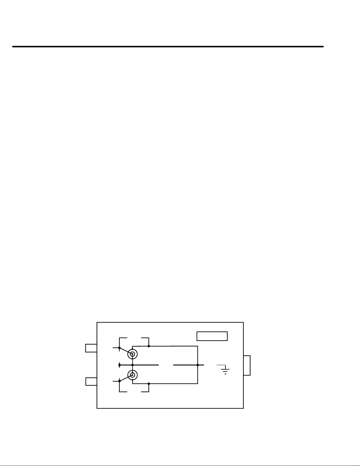
1-10 Getting Started
High voltage differentials — Exceeding the high voltage differentials (42V peak and 250V
peak) could damage the instrument and create a shock hazard.
Remote PreAmp connector:
REMOTE PREAMP Connect the Remote PreAmp to the mainframe using the supplied
Interlock and digital input/output port:
INTERLOCK — DIGITAL I/O Male DB-9 connector for digital output lines, interlock, and
Power module:
Contains the AC line receptacle and the power line fuse.
Trigger link connector:
TRIGGER LINK 8-pin micro-DIN connector for sending and receiving trigger pulses.
preamp cable (CA-176-1D).
component handler signals.
Use a trigger link cable or adapter, such as Models 8501-1, 8501-2,
8502, 8504.
Remote PreAmp summary
Figure 1-3
Remote preamp
RS-232 connector:
RS-232 Connector for RS-232 remote operation. Use a straight through (not
null modem) DB-9 cable such as Keithley Model 7009-5.
GPIB connector:
IEEE-488 INTERFACE Connector for GPIB remote operation. Use a shielded cable
(Model 7007-1 or 7007-2).
The Remote PreAmp is shown in Figure 1-3 and terminal identification for the IN/OUT
HIGH and SENSE triax connectors is provided in Figure 1-4.
SENSE
IN/OUT
HIGH
HI
40V
Peak
40V
Peak
HI
250V
Peak
250V
Peak
GUARD
250V
Peak
IN/OUT
LO
KEITHLEY
42V
Peak
MAINFRAME
REMOTE Preamp
Page 43

Getting Started 1-11
Fi
4
gure 1-
Triax
connectors
(Input/Output High)
HI
GUARD
(Cable Guard)
LO
(Input/Output Low)
IN/OUT HIGH Triax Connector
(4-Wire Sense High)
(Input/Output Low)
SENSE Triax Connector
HI
GUARD
(Cable Guard)
LO
Preamp connector:
MAINFRAME Connect the Remote PreAmp to the mainframe using the supplied preamp cable.
Triax connectors:
CAUTION When using the Remote PreAmp, DO NOT use the INPUT/OUTPUT HI
and 4-WIRE SENSE HI banana jacks on the mainframe. Using these
source-measure banana jacks will result in errors and/or noise, and possible damage to the Remote PreAmp.
IN/OUT HIGH HI Center conductor – Input/Output HI
Guard Inner shell – Driven cable guard for guarded measurements
LO Outer shell – Input/Output LO
SENSE HI Center conductor – 4-wire Sense HI
Guard Inner shell – Driven cable guard for guarded measurements
LO Outer shell – Input/Output LO
NOTE Cable guard is always available on the Guard terminals of IN/OUT HIGH and
SENSE regardless of the guard mode setting. Ohms guard can only be accessed at
the V,
Ω
GUARD banana jack on the mainframe.
The diagram on the Remote PreAmp (Figure 1-3) shows the maximum allowable voltage
differentials between the various terminals. Exceeding the voltage differentials could damage
the SourceMeter and create a shock hazard.
CAUTION Instrument damage caused by excessive voltage differentials is not covered
by the warranty.
Page 44

1-12 Getting Started
Power-up
WARNING To prevent electric shock, power must be off when connecting the Remote
WARNING During the power-up, voltage spikes may appear on the terminals of the
WARNING To prevent electric shock, test connections must be configured such that
PreAmp to the mainframe. If you wish to connect the Remote PreAmp at
this time, proceed to Section 2, Connecting Remote PreAmp to the
mainframe. Important safety precautions are included with the connection
procedure.
SourceMeter. These voltage spikes could be at hazardous levels (>42.4V
peak) and could damage sensitive DUTs. Never touch external circuitry or
the test leads when powering up the SourceMeter. It is good practice to
always disconnect DUTs from the SourceMeter before powering up the
unit.
the user cannot come in contact with conductors or any DUT that is in
contact with the conductors. Safe installation requires proper shields, barriers, and grounding to prevent contact with conductors. Operator protection and safety are the responsibility of the person installing the product.
Line power connection
The SourceMeter operates from a line voltage in the range of 85 to 250V at a frequency of
50 or 60Hz. The SourceMeter will also operate at 400Hz; accuracy specifications are not guaranteed howev er. Line voltage and line frequency are automatically sensed. Therefore, there are
no switches to set. Check to be sure the operating voltage in your area is compatible.
CAUTION Operating the instrument on an incorrect line voltage may cause damage,
possibly voiding the warranty.
Perform the following steps to connect the SourceMeter to line power and turn it on:
1. Before plugging in the power cord, make sure the front panel power switch is in the off
(0) position.
2. Connect the female end of the supplied power cord to the AC receptacle on the rear
panel.
WARNING The power cord supplied with the SourceMeter contains a separate ground
for use with grounded outlets. When proper connections are made, instrument chassis is connected to power line ground through the ground wire in
the power cord. Failure to use a grounded outlet may result in personal
injury or death due to electric shock.
3. Turn on the instrument by pressing the front panel power switch to the on (1) position.
Page 45

Power-up sequence
On power-up, the SourceMeter performs self-tests on its EPROM and RAM and momentarily lights all segments and annunciators. If a failure is detected, the instrument momentarily
displays an error message, and the ERR annunciator turns on. Error messages are listed in
Appendix B.
NOTE If a problem develops while the instrument is under warranty, return it to Keithley
Instruments, Inc., for repair.
If the instrument passes the self-tests, the firmware revision levels are displayed. For
example:
REV A01 A02
where: A01 is the main board ROM revision.
A02 is the display board ROM revision.
Also displayed is the line frequency (50, 60, or 400Hz). (If the wrong frequency is displayed, it can be manually set as covered belo w). The communication interf ace status is briefl y
displayed. If the IEEE-488 bus is the presently selected interface, the identification message
will include the primary address. For example, if the primary address is 24 (factory default), the
“IEEE Addr=24” message is displayed. If the RS-232 interface is selected, the “RS-232” message is displayed.
Getting Started 1-13
After the power-up sequence, the instrument goes to its normal display state with the output
off (red OUTPUT indicator light off). With the output off, the “OFF” message is displayed, and
dashes replace the reading. The “OFF” message indicates that the NORMAL output-off state is
selected. See Section 12, Output configuration for details.
System identification
To obtain the serial number and revision information, use the MENU/GENERAL/SERIAL #
selection or the *IDN? query via remote.
Line frequency setting
At the factory, the SourceMeter is configured to sense the power line frequency and automatically select the frequency setting. If, howev er, the line power source is noisy, the SourceMeter may select the wrong setting on power-up. If this situation occurs, noisy measurement
readings will result, and accuracy may be affected. You can manually set the line frequency
from the front panel or via remote as covered below.
Front panel line frequency
Set the line frequency from the front panel as follows:
1. Press the MENU key to display MAIN MENU.
Page 46

1-14 Getting Started
2. Using the right arrow key, select AD-CTRL then press ENTER to display A/D
3. Select LINE-FREQ, then press ENTER to display LINE FREQUENCY.
4. Place the cursor on 50Hz, 60Hz, or AUTO, and press ENTER. (Use 50Hz for 400Hz
5. Press EXIT to return to normal display.
Remote command line frequency
Table 1-1 summarizes remote commands used to control line frequency. See Section 17 for
additional information on using these commands.
Programming examples
50 or 400Hz operation:
:SYST:LFR 50
Auto frequency operation:
CONTROLS.
operation.)
:SYST:LFR:AUTO ON
Table 1-1
Line frequency remote commands
Commands Description
:SYSTem:LFRequency <freq>
:SYSTem:LFRequency:AUTO <state>
Fuse replacement
A rear panel fuse protects the power line input of the SourceMeter. If the line fuse needs to
be replaced, perform the following steps:
1. The fuse is located in a drawer above the AC receptacle. See Figure 1-2. At the bottom
of the fuse drawer is a small tab. At this location, use a small bladed screwdriver to pry
the fuse drawer open.
2. Slide the fuse drawer out to gain access to the fuse. Note that the fuse drawer does not
pull all the way out of the power module.
CAUTION For continued protection against fire or instrument damage, replace the
Select line frequency (freq = 50 or 60).
Enable/disable auto frequency (state = ON or OFF).
fuse only with the type and rating listed. If the instrument repeatedly
blows fuses, locate and correct the cause of the problem before replacing
the fuse.
3. Snap the fuse out of the drawer and replace it with the same type (250V, 2.5A,
5 × 20mm). The Keithley part number is FU-72.
4. Push the fuse drawer back into the power module.
Page 47

Display
Display format
Getting Started 1-15
The SourceMeter display is used primarily to program source and compliance values and
display measured readings. Annunciators, which are located along the top of the reading/
message display, indicate various states of operation, as covered previously in Front panel
summary.
On power-up, the top (primary) display is used for measurements when the output is on
(with the output off, “OFF” or “ZER” is displayed). The bottom-left display is used for the programmed source value (Vsrc or Isrc), and the bottom-right display is used for the programmed
compliance (Cmpl) limit.
Reading information can be displayed using either engineering units or scientific notation in
either fixed- or floating-point format. Use the GENERAL/NUMBERS selection of the main
MENU to select the display format, as discussed under Menus later in this section.
Engineering units example: 1.23456µA
Scientific notation example: 1.23456e -6
EDIT key
The SourceMeter must be in the edit mode to set source and compliance values. The edit
mode is selected by pressing the EDIT key (EDIT annunciator on). The editing cursor (flashing
digit) appears for the source or compliance reading. If a value is not edited within six seconds,
the edit mode is cancelled. While in the edit mode, the EDIT key toggles between the source
value and compliance value. See Section 3 for details on setting source and compliance values.
TOGGLE key
The TOGGLE key manipulates readings on the top display and on the bottom-left display. It
has no effect on the compliance reading (Cmpl), which is located on the bottom right. Each
press of the TOGGLE key sequences through the display options.
With the voltage (V) or current (I) measurement function selected, the TOGGLE key lets
you display both the current and voltage measurements at the same time. It also allows you to
toggle display positions of the source and measure readings.
With the ohms (Ω) measurement function selected, the ohms measurement is always displayed on the top display. The TOGGLE key lets you display either the programmed source
value, the current measurement, or the voltage measurement on the bottom-left display .
The TOGGLE key is also used to display statistical data on readings stored in the data store.
This function is performed from the data store RECALL mode.
NOTE If FCTN, REL, or Limits is enabled, the TOGGLE key is disabled.
Page 48

1-16 Getting Started
Status and error messages
Status and error messages are displayed momentarily. During SourceMeter operation and
programming, you will encounter a number of front panel messages. Typical messages are
either status or error in nature and are listed in Appendix B.
Remote display programming
The display can also be controlled by various SCPI :DISPlay subsystem commands.
Table 1-2 summarizes basic commands. See :DISPlay subsystem in Section 17 for more information on using these commands and also Disabling front panel display later in this section.
Table 1-2
Basic display commands
Command Description
:DISPlay:ENABle <state> Enable/disable display (state = ON or OFF).
:DISPlay:CNDisplay Return to source-measure display.
:DISPlay:DIGits <n> Set display resolution (n = 4 to 7).
Front panel tests
Use the TEST/DISPLAY TESTS selection of the main MENU to test various aspects of the
front panel. Test selections include:
• KEYS — Front panel keys are tested. Pressing a key displays a message that identifies
that key. Pressing EXIT twice cancels this test.
• DISPLAY PATTERNS — Use this selection to turn on all display pixels and annunciators. Subsequent key presses cycle through tests that turn off annunciators and corner
pixels of each digit, turn on the rows of the top-left display digit, and turn on all annunciators and pixels of each digit in a sequential manner. Press EXIT to cancel this test.
• CHAR SET — This test displays special characters. Press EXIT to cancel the test.
See Menus later in this section for more menu information.
Disabling front panel display
Front panel display circuitry can be disabled to allow the instrument to operate at a higher
speed. While disabled, the display is frozen with the following message:
FRONT PANEL DISABLED
Press LOCAL to resume.
As reported by the message, all front panel controls (except LOCAL, TRIG, and OUTPUT
ON/OFF) are disabled.
Page 49

Getting Started 1-17
Front panel control
Front panel display circuitry is controlled from the DISABLE DISPLAY configuration
menu, which is accessed by pressing CONFIG and then EDIT (or TOGGLE). To select an
option (NOW, NEVER, SWEEP, or STORE), use the and keys to place the cursor on the
desired option, then press ENTER.
The options for DISABLE DISPLAY are explained as follows:
NOW — Select this option to disable the display now.
NEVER — Select this option if you do not want the display to disable.
SWEEP — Select this option if you want the display to disable while performing a sweep.
The display will disable as soon as sweep is started. The display will automatically re-enable
after the sweep is completed.
STORE — Select this option if you want the display to disable when storing source-measure
readings in the buffer. The display will disable as soon as the buffer is enabled. The display
will automatically re-enable after the storage process is completed. Note that with this
option, the display will disable while performing a sweep. Sweep readings are automatically
stored in the buffer.
▲
▲
Remote command programming
Use the following SCPI commands to enable or disable the front panel display circuitry:
:DISPlay:ENABLe OFF Disable the display
:DISPlay:ENABLe ON Enable the display
Default settings
By using appropriate menu selections, you can save and recall various instrument setups,
define the power-on configuration, or restore factory defaults as outlined below.
Saving and restoring user setups
You can save and restore up to five of your own user setups using the following procedures.
Saving setups
1. Select the various instrument operating modes you wish to save.
2. Press the MENU key, select SAVESETUP, then press ENTER.
3. From the SAVESETUP menu, select GLOBAL, then press ENTER.
4. From the GLOBAL SETUP MENU, select SAVE, then press ENTER.
5. Select the setup position (0-4) to save, then press ENTER to complete the process.
Page 50

1-18 Getting Started
Restoring setups
1. Press the MENU key, select SAVESETUP, then press ENTER.
2. From the SAVESETUP menu, select GLOBAL, then press ENTER.
3. From the GLOBAL SETUP MENU, select RESTORE, then press ENTER.
4. Select the setup position (0-4) to restore, then press ENTER to complete the process.
Power-on configuration
You can also define which of the stored setups (factory default or user) the instrument
assumes as the power-on configuration as follows:
1. Press the MENU key, select SAVESETUP, then press ENTER.
2. From the SAVESETUP menu, select GLOBAL, then press ENTER.
3. From the GLOBAL SETUP MENU, select POWERON, then press ENTER.
4. From the SET POWER-ON DEFAULT menu, choose the power-on configuration:
5. If you chose to use a user setup as the power-on configuration, select the user setup
BENCH or GPIB (see below), or USER-SETUP-NUMBER.
number, then press ENTER.
Factory default settings
As summarized in Table 1-3, there are two sets of factory defaults, BENCH (front panel) and
GPIB (remote). You can restore either of these default conditions as follows:
1. Press the MENU key, select SAVESETUP, then press ENTER.
2. From the SAVESETUP menu, select GLOBAL, then press ENTER.
3. From the GLOBAL SETUP MENU, select RESET, then press ENTER.
4. Select BENCH or GPIB defaults as desired, then press ENTER to complete the
process.
Page 51

Table 1-3
Factory default settings
Setting BENCH default GPIB default
A/D Controls:
Auto-zero On On
Line frequency No effect No effect
Beeper On On
Data Store No effect No effect
Digital output* 15 or 7 15 or 7
Digits 5.5 5.5
FCTN Power (off) Power (off)
Filter: On On
Auto filter On On
Moving filter count** 1 1
Advanced filter Off (5% noise tol) Off (5% noise tol)
Median filter rank** 0 0
Repeat filter count** 1 1
GPIB address No effect No effect
Guard Cable Cable
Limit tests:
DigOut:
Size 4-bit 4-bit
Mode: Grading Grading
Binning control Immediate Immediate
Auto clear: Disabled Disabled
Delay 0.00001 sec 0.00001 sec
Clear pattern* 15 or 7 15 or 7
H/W limits:
Control Disabled Disabled
Fail mode: In compliance In compliance
Cmpl pattern* 15 or 7 15 or 7
S/W limits:
Lim 2, 3, 5-12:
Control Disabled Disabled
Low limit: -1.0 -1.0
Low pattern* 15 or 7 15 or 7
High limit: +1.0 +1.0
High pattern* 15 or 7 15 or 7
Pass (all tests):
Pass pattern* 15 or 7 15 or 7
Source memory location Next Next
EOT mode EOT EOT
Numbers No effect No effect
Ohms source mode Manual Manual
Offset compensated ohms Off Off
Output Off Off
Interlock Disabled Disabled
Off state Normal Normal
Auto-off Disabled Disabled
* 15 if digout size is 4-bit, 7 if digout size is 3-bit.
** Changes with range when auto filter is enabled.
Getting Started 1-19
Page 52

1-20 Getting Started
Table 1-3 (cont.)
Factory default settings
Setting BENCH default GPIB default
Power-on default No effect No effect
Ranging (measure):
Auto range Enabled Enabled
Rel Off Off
Value 0.0 0.0
RS-232 No effect No effect
Source delay 3ms 3ms
Auto-delay Disabled Disabled
Speed Hi accuracy (10 PLC) Hi accuracy (10 PLC)
Sweep Linear staircase Linear staircase
Start 0V or 0A 0V or 0A
Stop 0V or 0A 0V or 0A
Step 0V or 0A 0V or 0A
Sweep count 1 1
Sweep Pts 2500 2500
Source ranging Best fixed Best fixed
Voltage protection NONE NONE
Triggered source:
Control Disabled Disabled
Scale factor +1.0 +1.0
Triggering:
Arm layer:
Trigger layer:
Event Immediate Immediate
Count 1 1
Output trigger Line #2, Off Line #2, Off
Event Immediate Immediate
Count 1 1
Output triggers Line #2, All off Line #2, All off
Delay 0.0 sec 0.0 sec
Remote setups
You can also save and recall setups via remote using the following SCPI commands:
• Save and recall user setups using *SAV and *RCL (Section 15).
• Restore GPIB defaults using *RST (Section 15).
• Restore bench defaults using :SYSTem:PRESet (Section 17).
• Save the power-on configuration using :SYSTem:POSetup (Section 17).
Page 53

Menus
Main menu
Table 1-4
Main menu
Getting Started 1-21
The following paragraphs discuss the main menu, configuration menus, and rules to navi-
gate menus.
Use the MENU key to access the Main Menu to select, configure, and/or perform various
instrument operations. These include default setup conditions, communications (GPIB or
RS-232), calibration, front panel tests, digital output states, auto zero and NPLC caching,
timestamp, numeric display format, and the beeper.
The Main Menu structure is summarized in Table 1-4. Use the Rules to navigate menus to
check and/or change menu options. Figure 1-5 shows the main menu tree.
Menu item
SAVESETUP
GLOBAL
SAVE
RESTORE
POWERON
RESET
SOURCE MEMORY
SAVE
RESTORE
COMMUNICATION
GPIB
RS-232
BAUD
BITS
PARITY
TERMINATOR
FLOW CTRL
1
BENCH
GPIB
USER SETUP NUMBER
Description Parameters
Configure setup conditions.
Control instrument settings.
Save present SourceMeter setup to memory location.
Return the SourceMeter to setup saved in memory.
Select the power-on default setup.
Powers-on to BENCH defaults.
Powers-on to GPIB defaults.
Powers-on to user setup.
Returns unit to BENCH or GPIB defaults.
Control memory sweep source setup configurations.
Save present setup configuration to memory location.
2
Return to configuration saved in memory location.
Select and configure remote interface.
Select GPIB (IEEE-488 Bus), set primary address, GPIB
protocol (see Appendix G).
Select the RS-232 interface, set parameters.
Select baud rate.
Select number of data bits.
Select parity.
Select terminator.
Select flow control.
0 to 4
0 to 4
See Table 1-3.
See Table 1-3.
0 to 4
See Table 1-3.
1 to 100
1 to 100
0 to 30
(Default: 24)
57600, 38400,
19200, 9600,
4800, 2400,
1200, 600, 300
7 or 8
NONE, ODD,
EVEN
CR, CR+LF, LF,
or LF+CR
NONE or
XON/XOFF
Page 54

1-22 Getting Started
Table 1-4 (cont.)
Main menu
Menu item
CAL
1
3
TEST
DISPLAY TESTS
KEYS
DISPLAY PATTERNS
CHAR SET
A/D CTRL
AUTO ZERO
5
DISABLE
ENABLE
ONCE
LINE FREQ
NPLC CACHE
DISABLE
ENABLE
REFRESH
RESET
GENERAL
DIGOUT
SERIAL#
TIMESTAMP
NUMBERS
BEEPER
Description Parameters
Calibrate SourceMeter. (See Section 19.)
Perform tests on SourceMeter.
4
Test front panel keys and display digits.
Test front panel keys.
Test display pixels and annunciators.
Test special display characters.
Control auto zero, line frequency, and NPLC caching.
Control auto zero.
Disable auto zero.
Enable auto zero.
Force auto zero immediate update.
Set the line frequency.
50 or 60Hz, or
AUTO
Control NPLC caching.
Disable NPLC caching.
Enable NPLC caching.
Update all NPLC values in cache immediately.
Clear NPLC cache of all NPLC values.
Select general operations.
Set Digital I/O port bit pattern.
Display serial number, firmware revision, SCPI version.
0-15
YES or NO
Reset timestamp.
Select engineering units or scientific notation display
format.
ENGR,
SCIENTIFIC
Enable or disable beeper.
NOTES
1. Top level menu choices indicated in bold. Indentation identifies each lower submenu level.
2. When the remote operation interface selection (GPIB or RS-232) is changed, the SourceMeter performs a power-on reset. To
check or change options of the selected interface, you must re-enter the menu structure.
3. Password is required to unlock calibration. (See Section 19.)
4. Press EXIT key to cancel test.
5. Disabling auto zero will reduce measurement accuracy.
Page 55

Getting Started 1-23
Fi
5
M
gure 1-
ain menu tree
Press MENU key (Use and to select item, then press ENTER)
SAVESETUP
GLOBAL
SAVE
RESTORE
POWERON
RESET
SOURCE MEMORY
SAVE
RESTORE
COMMUNICATION
GPIB
RS-232
BAUD
BITS
PARITY
TERMINATOR
FLOW-CTRL
CAL*
UNLOCK
EXECUTE
VIEW-DATES
SAVE
LOCK
CHANGE-PASSWORD
TEST
DISPLAY-TESTS
KEYS
DISPLAY-PATTERNS
CHAR-SET
A/D CTRL
AUTO-ZERO
LINE-FREQ
NPLC-CACHE
GENERAL
DIGOUT
SERIAL#
TIMESTAMP
NUMBERS
BEEPER
▲
▲
BENCH
GPIB
USER-SETUP-NUMBER
* Without PreAmp connected
Page 56

1-24 Getting Started
Rules to navigate menus
Many source-measure functions and operations are configured from the front panel menus.
Use the following rules to navigate through these configuration menus:
NOTE Rules to edit source and compliance values are found in Section 3, “Basic source-
measure procedure.”
• A menu item is selected by placing the cursor on it and pressing ENTER. Cursor position is denoted by the blinking menu item or option. The left and right arrow keys control cursor position.
• A displayed arrow on the bottom line indicates there are one or more additional items
(or messages) to select from. Use the appropriate cursor key to display them.
• A source or parameter value range is changed by placing the cursor on the range desig-
▲
nator (i.e., k, M, G, etc.) and using the SOURCE
that when the next higher or lower source range is selected, the reading increases or
decreases by a decade.
• A parameter value is k eyed in by placing the cursor on the digit to be changed and using
one of the following methods:
or ▼ or RANGE ▲ or ▼ keys. Note
NOTE You can clear a parameter value by pressing the MENU key.
- Use the SOURCE
digit.
- Use the number keys (0 through 9) to key in the value at the selected digit.
- Use the ± key to change source value polarity, regardless of cursor position.
• Boolean selections (such as ON/OFF and HIGH/LOW) are toggled by placing the cursor on the selection and pressing a SOURCE or RANGE up or down arrow key.
• A change is only executed when ENTER is pressed. Entering an invalid parameter generates an error, and the entry is ignored. Howev er, entering an out-of-range value (too
small or too large) selects the lower or upper limit, respectively.
• The EXIT key is used to back out of the menu structure. Any change that is not entered
is cancelled when EXIT is pressed.
or ▼ or RANGE ▲ or ▼ keys to increment or decrement the
▲
Page 57

Editing source and compliance values
Use the following keys to edit source and compliance values:
• EDIT: selects the source or compliance display field for editing. A blinking cursor will
appear in the field to be edited. If no key is pressed within a few seconds, the edit mode
will be cancelled automatically.
• EDIT and : places the display cursor on the display digit to be changed.
• SOURCE
pressing either of these keys will automatically enable the source edit mode.
• RANGE
• Numeric keys (0-9): allow you to directly enter source or compliance values.
• EXIT: exits the edit mode without waiting for the time-out period.
The basic procedure for editing source and compliance values is outlined below . See Basic
source-measure procedure in Section 3 for more details.
1. Press the EDIT key until the blinking cursor is in either the source or compliance display field to be edited.
2. If desired, use the RANGE
range.
3. T o simply increment or decrement the display value, use the EDIT and keys to
place the blinking cursor on the digit to be changed, then increment or decrement the
value with the SOURCE
be updated immediately; you need not press ENTER to complete the process.
4. T o enter the source or compliance value directly, simply key in the desired value with
the numeric keys while the cursor is blinking. Again, the source or compliance value
will be updated immediately.
▲
▲
or ▼: increments or decrements the source or compliance value. Note that
▲
or ▼: selects the source or compliance range.
▲
and ▼ keys to select the desired source or compliance
▲
and ▼ keys. Note that the source or compliance value will
▲
Getting Started 1-25
▲
▲
Toggling the source and measure display fields
Normally the measured reading value will appear in the upper, main display line, while the
source and compliance values will appear in the left and right fields respectively of the lower
display line. You can toggle the source and measure display fields by pressing the TOGGLE
key to place the source and measure values in the desired positions.
Page 58

1-26 Getting Started
Configuration menus
There are a number of configuration menus that can be accessed by pressing the CONFIG
key followed by the appropriate function or mode key. For example, you can configure the voltage source by pressing CONFIG then SOURCE V. Configuration menus, which are summarized in Table 1-5 through T able 1-10, are available for the following operating modes:
These various configuration menus are covered in detail in the pertinent sections of this
manual.
• Measure functions (Ω, FCTN): Table 1-5.
• SOURCE V, SOURCE I, and RANGE: Table 1-6.
• REL, FILTER, and LIMIT: Table 1-7.
• TRIG: Table 1-8.
• SWEEP, DIGITS, SPEED, and STORE: Table 1-9.
• ON/OFF OUTPUT and Display (EDIT or TOGGLE): Table 1-10.
Page 59

Table 1-5
Measurement configuration menus
Configuration menu item Description
CONFIG MEAS Ω Configure ohms measure.
CONFIG OHMS
SOURCE Select manual or auto source for ohms.
MANUAL
AUTO
GUARD Select ohms or cable guard.
OHMS
CABLE
SRC RDBK Enable/disable source readback.
DISABLE
ENABLE
OFFSET COMPENSATION Enable/disable offset compensation.
DISABLE
ENABLE
Getting Started 1-27
CONFIG FCTN Configure functions.
CONFIGURE FUNCTION
POWER Enable power function.
OFF COMP OHMS Enable offset-compensated ohms, program parameters.
VOLT -COEFF Enable voltage coefficient, program parameters.
VAR ALPHA Enable varistor alpha, program parameters.
%DEV Enable percent deviation, program parameters.
Page 60

1-28 Getting Started
Table 1-6
Source and range configuration menus
Configuration menu item Description
CONFIG SOURCE V Configure V source.
CONFIGURE V SOURCE
PRO TECTION Select voltage protection.
DELAY Program delay between source and measure.
AUTO DELAY Enable/disable auto delay.
GUARD Select ohms or cable guarding.
TRIG Control triggered source.
DISABLE
ENABLE
OHMS
CABLE
CONTROL Enable/disable triggered source.
DISABLE
ENABLE
SCALE FACTOR Program scale factor.
CONFIG SOURCE I Configure I source
CONFIGURE I SOURCE
GUARD Select ohms or cable guarding.
OHMS
CABLE
DELAY Program delay between source and measure.
AUTO DELAY Enable/disable auto delay.
DISABLE
ENABLE
TRIG Control triggered source.
CONTROL Enable/disable triggered source.
DISABLE
ENABLE
SCALE FACTOR Program scale factor.
CONFIG ▲ RANGE Program upper range limit.
CONFIG ▼ RANGE Program lower range limit.
CONFIG AUTO RANGE
AUTO RANGE TYPE Select auto range type.
SINGLE SRC MTR Select single SourceMeter operation.
MULTIPLE Select multiple SourceMeter, program soak time.
Page 61

Getting Started 1-29
Table 1-7
Rel, filter, and limit configuration menus
Configuration menu item Description
CONFIG REL Program REL value.
CONFIG FILTER Configure filter.
AUTO FILTER Enable/disable auto filter.
DISABLE
ENABLE
CONFIG LIMIT Configure limit tests.
CONFIGURE LIMITS MENU
DIGOUT Program Digital I/O bit patterns for pass/fail.
SIZE Select I/O number of bits.
3-BIT 3-bit size
4-BIT 4-bit size
16-BIT 16-bit size (2499-DIGIO option only).
MODE Select Digital I/O mode.
GRADING Pass if within HI/LO limits.
IMMEDIATE Stop test after first failure.
END Stop test at end of sweep.
SORTING Fail if outside limits, program fail pattern.
AUTO CLEAR Enable/disable auto clear.
DISABLE Disable auto clear.
ENABLE Enable auto clear, program pass/fail pattern.
H/W LIMITS Control and set fail mode for Limit 1 (compliance) test.
CONTROL Control Limit 1 test.
DISABLE Disable Limit 1 test.
ENABLE Enable Limit 1 test.
FAIL MODE Select Limit 1 fail mode.
IN Fail when in compliance, program bit pattern.
OUT Fail when out of compliance, program bit pattern.
S/W LIMITS Control LIM2, 3, 5-12 tests limits and bit patterns.
CONTROL Enable/disable limit tests.
DISABLE Disable test.
ENABLE Enable test.
LOLIM Set low limit.
HILIM Set high limit.
PASS Set pass Digital I/O bit pattern.
PASS Set limit test pass conditions.
DIGIO PATTERN Set pass conditions Digital I/O bit pattern.
SRC MEM LOC Set pass conditions next source memory location.
NEXT Use next location.
LOCATION# Specify location number.
EOT MODE Set Digital I/O line 4 to act as EOT or BUSY signal.
BUSY Set line 4 HI while unit is busy (3-bit mode).
/BUSY Set line 4 LO while unit is busy (3-bit mode).
EOT Output line 4 HI pulse at end of test (3-bit mode).
/EOT Output line 4 LO pulse at end of test (3-bit mode).
Page 62

1-30 Getting Started
Table 1-8
Trigger configuration menu
Configuration menu item Description
CONFIG TRIG Configure triggering.
CONFIGURE TRIGGER
ARM LAYER Configure trigger model arm layer.
TRIG LAYER Configure trigger layer of trigger model.
HALT Return unit to idle state.
ARM IN Select arm layer detection event.
IMMEDIATE Immediate event detection.
GPIB GPIB GET or *TRG.
TIMER After timer interval elapses, enter interval.
MANUAL Front panel TRIG key.
TLINK Enter TLINK line and state.
ONCE Bypass event detection once.
NEVER Never bypass event detection.
↓STEST When Digital I/O SOT line is pulsed low.
ONCE Bypass event detection once.
NEVER Never bypass event detection.
↑STEST When Digital I/O SOT is pulsed high.
ONCE Bypass event detection once.
NEVER Never bypass event detection.
↑↓STEST When Digital I/O SOT line is pulsed high or low.
ONCE Bypass event detection once.
NEVER Never bypass event detection.
ARM OUT Configure arm layer output trigger.
LINE Select trigger link output line (1-4).
EVENTS Enable/disable events.
TRIG LAYER EXIT Enable (ON) or disable (OFF) on exiting trigger layer.
TL ENTER Enable (ON) or disable (OFF) on entering trigger layer.
COUNT Specify arm count.
FINITE Programmable count.
INFINITE Never ending count.
TRIGGER IN Select trigger layer detection event.
IMMEDIATE Trigger event occurs immediately.
TRIGGER LINK Select trigger link line as event (1-4).
TRIGGER OUT Configure trigger layer output trigger.
LINE Select trigger link line (1-4).
EVENTS Enable (ON) or disable (OFF) for SOURCE, DELAY,
and MEAS.
DELAY Program trigger delay time.
COUNT Program trigger count.
Page 63

Getting Started 1-31
Table 1-9
Sweep, digits, speed, and data store configuration menus
Configuration menu item Description
CONFIG SWEEP Configure sweeps.
CONFIGURE SWEEPS
TYPE Select sweep type.
STAIR Staircase sweep, program START, STOP, STEP.
LOG Log sweep, program START, STOP, # POINTS.
CUSTOM Custom sweep, program parameters.
# POINTS Program number of sweep points.
ADJUST POINTS Set individual point values.
INIT Set first point value.
SRC MEMORY Source memory sweep, set parameters.
START Set first point value.
# POINTS Set number of points.
SWEEP COUNT Set sweep count.
FINITE Program sweep count value.
INFINITE Never-ending sweep.
SOURCE RANGING Set sweep ranging mode.
BEST FIXED Best fixed range based on maximum value.
AUTO RANGE Auto range during sweep.
FIXED Set fixed source range.
CONFIG DIGITS Set display number of digits.
DISPLAY DIGITS Select 3.5, 4.5, 5.5, or 6.5.
CONFIG SPEED Set measurement speed.
SPEED ACCURACY MENU
FAST Fast speed.
MED Medium speed.
NORMAL Normal.
HI ACCURACY Maximum accuracy.
OTHER Program NPLCs (number power line cycles).
CONFIG STORE Configure data store timestamp.
STORE TIMESTAMP
ABSOLUTE Absolute timestamp.
DELTA Delta timestamp.
Page 64

1-32 Getting Started
Table 1-10
Output and display configuration menus
Configuration menu item Description
CONFIG ON/OFF OUTPUT Configure output.
CONFIGURE OUTPUT
OFF STATE Set up output off state.
AUTO OFF Enable disable auto off mode.
INTERLOCK Enable/disable interlock.
CONFIG EDIT or TOGGLE Enable/disable display.
DISABLE DISPLAY
NOW Disable display immediately.
NEVER Never disable display.
SWEEP Turn display off during sweep.
STORE Turn display off during buffer store.
NORMAL Normal off state.
ZERO Zero off state.
GUARD Guard mode off state.
DISABLE Keep output on.
ENABLE Turn output off after each measurement.
DISABLE Disable interlock.
ENABLE Enable interlock.
Page 65

2
Connections
• Connection Overview — Explains how to connect the Remote PreAmp to the mainframe, provides basic information on the input/output connectors, and discusses using a
test fixture interlock.
• Connections to DUT — Covers various methods for making connections to the DUT ,
including 4-wire remote sensing, 2-wire local sensing, cable and ohms guard, as well as
guard selection.
• Guarding Methods — Discusses different guarding methods including cable guard,
ohms guard, and guard selection.
Page 66

2-2 Connections
Connection overview
WARNING To prevent electric shock, test connections must be configured such that
the user cannot come in contact with conductors or any DUT that is in
contact with the conductors. Safe installation requires proper shields, barriers, and grounding to prevent contact with conductors. Operator protection and safety are the responsibility of the person installing the product.
WARNING During power-up, voltage spikes may appear on the terminals of the
SourceMeter. These voltage spikes could be at hazardous levels (>42.4V
peak) and could damage sensitive DUTs. Never touch external circuitry or
the test leads when powering up the SourceMeter. It is good practice to
always disconnect DUTs from the SourceMeter before powering up the
SourceMeter.
WARNING Up to 210V may be present on the output and guard terminals. To prevent
electrical shock that could cause injury or death, NEVER make or break
connections to the SourceMeter while it is on or is connected to an external
source.
Connecting Remote PreAmp to the mainframe
WARNING Potentially hazardous source voltage is routed from the mainframe to the
Remote PreAmp via the preamp cable. Adhere to the following safety precautions to prevent electric shock:
• The SourceMeter must be turned off before connecting (or disconnecting) the Remote PreAmp to the mainframe.
• When not using the Remote PreAmp, disconnect the preamp cable at
the rear panel of the mainframe. DO NOT leave the preamp cable connected to the mainframe if the other end is not connected to the Remote
PreAmp.
• ALWAYS re-install the plastic safety cover onto the mainframe preamp
connector whenever the Remote PreAmp is not being used.
Use the supplied preamp cable to connect the Remote PreAmp to the mainframe as follows:
1. From the front panel of the SourceMeter, turn the POWER off.
2. Connect the preamp cable to the Remote PreAmp. The preamp connector on the
Remote PreAmp is labeled “MAINFRAME.”
Page 67

3. At the rear panel of the mainframe, remove the plastic safety cover from the preamp
connector. This connector is labeled “REMOTE PreAmp.” The plastic cover is secured
to the connector with two screws. Hold on to the plastic cov er and the retaining screws.
Whenever the Remote PreAmp is not being used, the plastic safety cover must be reinstalled on the mainframe preamp connector.
4. Connect the other end of the preamp cable to the mainframe.
Source-measure terminals
The SourceMeter can be used with or without the Remote PreAmp. However, when not
using the Remote PreAmp, the lower current ranges and higher resistance ranges are not available. The small Remote PreAmp can be positioned near the DUT allowing the use of short triax
cables. Short triax cables help minimize cable capacitance which could adversely affect the
response time of low current measurements.
When not using the Remote PreAmp, all connections to the SourceMeter are made at the
rear panel of the mainframe using cables terminated with banana plugs. These terminals are
summarized in Section 1 (Figure 1-2). When using the Remote PreAmp, not all source-measure terminals are available at the preamp and must be accessed at the mainframe. Table 2-1
lists each mainframe terminal and the equivalent Remote PreAmp terminal.
Connections 2-3
Table 2-1
Terminal equivalency between mainframe and Remote PreAmp
Mainframe terminal Equivalent Remote PreAmp terminal
INPUT/OUTPUT HI
INPUT/OUTPUT LO
4-WIRE SENSE HI
4-WIRE SENSE LO
V, Ω GUARD
GUARD SENSE
Chassis ground (screw)
N/A = Not available at Remote PreAmp.
NOTE Whenever the Remote PreAmp is connected to the mainframe, adhere to the follow-
ing rules to achieve best performance:
• Do not use INPUT/OUTPUT HI and 4-WIRE SENSE HI on the mainframe.
Access these terminals at the Remote PreAmp.
• Access input/output low at the Remote PreAmp or at the mainframe, but not both.
Test circuit common should be tied to one point to avoid ground loops which
could generate error currents.
• Do not use guard from the mainframe and the Remote PreAmp at the same time.
Use one or the other.
IN/OUT HI
IN/OUT LO
SENSE HI
N/A
GUARD (cable guard only)
N/A
N/A
Page 68

2-4 Connections
p
Remote PreAmp triax connectors
conductor of the connector (and triax cable) is HI (input/output or sense), and the inner shield
is cable guard. The outer shield (shell) of each triax connector is input/output LO.
NOTE The 6430-322-1A triax cable (which is a supplied accessory) is terminated with a
floating source-measure operations, a voltage potential will be present on the shells of the triax
connectors. Even with the output of the SourceMeter off, voltage could be applied from the
external test circuit. As a general rule, do not touch the triax cables while any power is present.
WARNING To prevent injury from electric shock, DO NOT touch the triax cables of
The electrical configuration of each triax connector is shown in Figure 2-1A. The center
triax connector on one end and booted alligator clips on the other end. (See Figure
2-1B.) When connected to the Remote PreAmp, the alligator clip with the red boot is
HI, the one with the black boot is GUARD and the one with the green boot is LO.
The outer shells of the triax connectors are connected to Input/Output LO. Therefore, for
the Remote PreAmp while the SourceMeter is turned on or any external
source is turned on.
Figure 2-1
Basic input/output
configurations
Center Conductor
Inner Shield
Outer Shield
A) Remote PreAmp Triax Connector Configuration
6430 Mainframe
INPUT/OUTPUT
Zener
Clamp
Chassis
Ground
Triax to Alligator Clip
HI (center conductor)
Guard (inner shield)
LO (outer shell)
HI (In/Out or Sense)
GUARD (Cable)
LO (In/Out)
HI
LO
42V Peak DC Max
Chassis Ground Screw
or
10.5mA Max
(on Rear Panel)
Red boot
Black boot
Green boot
B) Terminal identification for 6430-322-1A cable
C) Mainframe In
ut/Output Configuration
Page 69

Connections 2-5
Input/output LO and chassis ground
Input/Output LO is not directly connected to chassis ground. For test circuits that require
Input/Output LO connected to chassis ground, you can use the supplied chassis ground plug.
Connect the lug end of the cable to the chassis ground screw on the rear panel of the mainframe, and plug the other end into the INPUT/OUTPUT LO banana jack.
With no Input/Output LO-to-chassis ground connection, floating source-measure operations
(up to 42V peak) can be performed. Inside the mainframe, a zener clamp (Figure 2-1C) is used
to isolate Input/Output LO from the chassis.
WARNING Exceeding 42V between Input/Output LO and chassis ground creates a
shock hazard and could cause damage to the SourceMeter that is not covered by the warranty.
CAUTION Do not connect any external sources between Input/Output LO and chassis
ground. Current exceeding 10.5mA will damage the zener clamp
(Figure 2-1C). Such damage is not covered by the warranty.
Test fixture interlock
A test fixture interlock switch can be used with the SourceMeter to help protect the DUT.
The SourceMeter output will turn off when the lid of the test fixture is opened. However , you
must ALW AYS assume that power is present until you verify that the SourceMeter output is
off.
WARNING To prevent electric shock, test connections must be configured such that
the user cannot come in contact with conductors or any DUT that is in
contact with the conductors. Safe installation requires proper shields, barriers, and grounding to prevent contact with conductors. Operator protection and safety are the responsibility of the person installing the product.
See Section 12 for complete details on using the interlock and output configuration
information.
Page 70

2-6 Connections
Connections to DUT
NOTE Connection drawings in this manual are shown using the Remote PreAmp. If not
using the Remote PreAmp, make connections to the equivalent banana jack terminals on the rear panel of the mainframe.
WARNING To prevent injury from electric shock, DO NOT touch the triax cables of
the Remote PreAmp while the SourceMeter is turned on or is connected to
an external source that is turned on.
CAUTION When using the Remote PreAmp, DO NOT use the INPUT/OUTPUT HI
and 4-WIRE SENSE HI banana jacks on the mainframe. Using these terminals while the Remote PreAmp is plugged in will result in errors and/or
noise, and possible damage to the Remote Amplifier.
Sensing methods
Figure 2-2
Two-wire
sense
connections
Basic source-measure operations are performed using either 2-wire sense connections
(Figure 2-2) or 4-wire sense connections (Figure 2-3). See Section 4, Ohms sensing for
additional information.
*Keithley part number: CA-176-1D.
Preamp Cable*
MAINFRAME
Connect to REMOTE
PreAmp connector on rear
panel of mainframe
HI
DUT
LO
Connect to earth safety
ground using #18 AWG
wire or larger
Noise Shield
Triax Cable
Test
Fixture
WARNING
IN/OUT
HIGH
SENSE
Guard is at the same voltage level as
input/output high. Therefore, if a
hazardous voltage (≥42V peak) is
present on input/output high, it is also
present on the guard terminals of the
Remote PreAmp and mainframe.
KEITHLEY
6430
REMOTE
PreAmp
Page 71

Connections 2-7
WARNING:NO INTERNAL OPERATOR SERVICABLE PARTS,SERVICE BY QUALIFIED PERSONNEL ONLY.
WARNING:NO INTERNAL OPERATOR SERVICABLE PARTS,SERVICE BY QUALIFIED PERSONNEL ONLY.
CAUTION:FOR CONTINUED PROTECTION AGAINST FIRE HAZARD,REPLACE FUSE WITH SAME TYPE AND RATING.
CAUTION:FOR CONTINUED PROTECTION AGAINST FIRE HAZARD,REPLACE FUSE WITH SAME TYPE AND RATING.
Figure 2-3
Four-wire sense
connections
Noise Shield
LO
DUT
Sense
LO
Test
Fixture
Sense HI
Connect to earth safety
ground using #18 AWG
wire or larger
Banana Plug Cable
HI
250V
PEAK
Cable
Cable
4-WIRE
SENSE
Triax
Triax
WARNING
HI
5V
PEAK
LO
INPUT/
OUTPUT
IEEE-488
(ENTER IEEE ADDRESS
WITH FRONT PANEL MENU)
IN/OUT
HIGH
SENSE
Guard is at the same voltage level as
input/output high. Therefore, if a
hazardous voltage (≥42V peak) is
present on input/output high, it is also
present on the guard terminals of the
Remote PreAmp and mainframe.
5V
PK
V, Ω,
GUARD
5V
250V
PEAK
PEAK
GUARD
SENSE
42V
PEAK
RS232
6430 Mainframe
(rear panel connectors)
*Keithley part number: CA-176-1D.
KEITHLEY
Preamp Cable*
6430
REMOTE
PreAmp
TRIGGER
LINK
MADE IN
U.S.A.
MAINFRAME
REMOTE
!
PreAmp
LINE FUSE
SLOWBLOW
2.5A, 250V
LINE RATING
100-240VAC
50, 60, HZ
100VA MAX
INTERLOCK-
DIGITAL I/O
WARNING There is no direct internal connection between earth ground and the
INPUT/OUTPUT LO terminal of the SourceMeter. Therefore, hazardous
voltages (>30V rms) can appear on the LO terminal. Typically, this can
occur when the SourceMeter is operating in any mode where the output
changes rapidly, such as quick, pulsed waveforms that can be generated
using the ZERO, AUTO-OFF output state, or fast pulse sweep operations.
To eliminate the shock hazard, connect the INPUT/OUTPUT LO terminal
to earth ground. You can connect the LO terminal to the chassis ground
screw terminal on the rear panel using the supplied chassis ground plug, or
connect it to a known safety earth ground.
WARNING For floating source-measure operations, voltage will be present on the
outer shell (IN/OUT LO) of the triax cable(s). If IN/OUT LO is connected
to a noise shield as shown in Figures 2-2 and 2-3, the floating voltage will
also be present on the shield. To prevent contact with the floating voltage,
enclose the test circuit in a metal test fixture that is connected to safety
earth ground (as shown in Figures 2-2 and 2-3), and do not touch the triax
cable(s).
Page 72

2-8 Connections
2-wire sensing
drops in the test leads could be significant. The ratio between the test lead resistance and DUT
resistance determines the error that is introduced. If the error introduced by the IR drop of the
test leads is not acceptable, use 4-wire sensing.
When using 2-wire sensing to source and/or measure voltage, the error associated with IR
For example, assume test lead resistance (R
) is 1Ω and the DUT resistance (R
L
DUT
) is
10kΩ. The error is calculated as follows:
Error = R
L
/ R
DUT
= 1Ω / 10kΩ
= 0.0001
= 0.01%
Notice that as the resistance of the DUT increases, the error decreases. For DUT above
1GΩ, guarding should also be used. See Cable guard.
Since current in a series circuit is the same at all points in the loop, remote sensing does not
improve I-Source or I-Measure accuracy . Thus, if sourcing current and measuring current, you
can use local sensing.
NOTE For Measure Only (V or I) operation, 2-wire sensing must be used.
4-wire sensing
Voltage source and measure accuracy are optimized by using 4-wire sense connections.
When sourcing voltage, 4-wire sensing ensures that the programmed voltage is delivered to the
DUT . When measuring voltage, only the voltage drop across the DUT is measured.
Use 4-wire sensing for the following source-measure conditions:
• The error contributed by test lead resistance for local sensing is not acceptable.
• Optimum Ohms, V-Source, and/or V-Measure accuracy are required.
4-wire sensing specification clarifications
• There is no hardware configurations needed to enable 4-wire sense. Simply hook up the
sense wires; otherwise, the Model 6430 will sense the voltage locally through resistors.
• Specified accuracies for both source and measure are only achieved using 4-wire
sensing.
• Sense wires must be no more than 10Ω per lead.
Page 73

• The Model 6430 will perform to rated specification with up to 1V drop per source lead
H
on the 100µA through 100mA ranges. On the 10µA range and below (when using the
Remote PreAmp), the allowable voltage drop in each source lead is limited as follows:
Current range
10µA
1µA
100nA
10nA
1nA
100pA
10pA
1pA
Guarding methods
Connections 2-9
Maximum allowable resistance
per source lead
10Ω
50Ω
500Ω
5kΩ
50kΩ
1MΩ
50MΩ
1GΩ
Cable guard
Use the high-impedance (cable) guard connection scheme shown in Figure 2-4 for the fol-
lowing source-measure condition:
• Test circuit impedance is >1GΩ.
Figure 2-4
igh-impedance
guarding
HI
DUT
Connect to earth
safety ground using
#18 AWG wire or
Guard
LO
larger
Test Fixture
Triax Cable
Guard
Shield
WARNING
IN/OUT
HIGH
SENSE
Guard is at the same voltage level as
input/output high. Therefore, if a
hazardous voltage (≥42V peak) is
present on input/output high, it is also
present on the guard terminals of the
Remote PreAmp and mainframe.
KEITHLEY
6430
REMOTE
PreAmp
Cable guard is always available at the Remote PreAmp. If not using the Remote PreAmp,
use the V, Ω GUARD banana jack on the mainframe with CABLE guard selected. See Guard
selection to select cable guard.
A test fixture is typically used when testing high-impedance devices. The test fixture reduces
noise and protects the user from a potentially hazardous voltage on the guard shield (or plate).
See Section 5, Guard for details on using guard.
*Keithley part number: CA-176-1D.
Preamp Cable*
MAINFRAME
Connect to
REMOTE PreAmp
connector on rear
panel of mainframe
Note that the test fixture chassis is connected to In/Out LO to reduce noise.
Page 74

2-10 Connections
WARNING:NO INTERNAL OPERATOR SERVICABLE PARTS,SERVICE BY QUALIFIED PERSONNEL ONLY.
WARNING:NO INTERNAL OPERATOR SERVICABLE PARTS,SERVICE BY QUALIFIED PERSONNEL ONLY.
CAUTION:FOR CONTINUED PROTECTION AGAINST FIRE HAZARD,REPLACE FUSE WITH SAME TYPE AND RATING.
CAUTION:FOR CONTINUED PROTECTION AGAINST FIRE HAZARD,REPLACE FUSE WITH SAME TYPE AND RATING.
Ohms guard
select ohms guard.
NOTE Ohms guard cannot be accessed from the Remote PreAmp. It is only available at the
single resistor (DUT) in a resistor network. See Section 4, 6-wire ohms measurements and
Section 5, Guard for more information on guarded ohms measurements.
Use ohms guard for the following source-measure operation:
• In-circuit resistance measurements on the DUT where other parasitic leakage devices
are present.
Note that ohms guard must be selected for this connection scheme. See Guard selection to
rear panel of the mainframe.
Figures 2-5, 2-6, and 2-7 show how to make connections to measure the resistance of a
Figure 2-5
Guarded ohms
connections (basic)
Resistor
Network
I
G
R
G
≥1kΩ
DUT
Ohms
Guard
HI
LO
Triax Cable
WARNING
250V
PEAK
4-WIRE
SENSE
(ENTER IEEE ADDRESS
WITH FRONT PANEL MENU)
*Keithley part number: CA-176-1D.
IN/OUT
HIGH
SENSE
KEITHLEY
6430
REMOTE
PreAmp
Guard is at the same voltage level as
input/output high. Therefore, if a
hazardous voltage (≥42V peak) is
present on input/output high, it is also
present on the guard terminals of the
Remote PreAmp and mainframe.
Banana Plug Cable
6430 Mainframe (rear panel connectors)
5V
HI
5V
PEAK
LO
IEEE-488
INPUT/
OUTPUT
PK
V, Ω,
GUARD
5V
250V
PEAK
PEAK
GUARD
SENSE
42V
PEAK
RS232
TRIGGER
LINK
MADE IN
U.S.A.
Preamp
MAINFRAME
REMOTE
!
PreAmp
LINE FUSE
SLOWBLOW
2.5A, 250V
LINE RATING
100-240VAC
50, 60, HZ
100VA MAX
INTERLOCK-
DIGITAL I/O
Cable*
Page 75

Connections 2-11
WARNING:NO INTERNAL OPERATOR SERVICABLE PARTS,SERVICE BY QUALIFIED PERSONNEL ONLY.
WARNING:NO INTERNAL OPERATOR SERVICABLE PARTS,SERVICE BY QUALIFIED PERSONNEL ONLY.
CAUTION:FOR CONTINUED PROTECTION AGAINST FIRE HAZARD,REPLACE FUSE WITH SAME TYPE AND RATING.
CAUTION:FOR CONTINUED PROTECTION AGAINST FIRE HAZARD,REPLACE FUSE WITH SAME TYPE AND RATING.
The basic connection scheme for guarded ohms measurements is shown in Figure 2-5. If the
guard resistance path (R
) is <1kΩ, IR drop in the GUARD test lead could be high enough that
G
the guard voltage at the resistor netw ork is significantly less than the output v oltage at the DUT.
This results in leakage current and will corrupt the measurement. To cancel the effect of IR
drop in the GUARD test lead, connect GUARD SENSE to the resistor network as shown in
Figure 2-6. Guard sense ensures that the guard voltage at the resistor network is the same as the
output voltage at the DUT .
Figure 2-6
Guarded ohms
connections
(guard sense)
Resistor
Network
I
G
R
G
<1kΩ
DUT
Ohms
Guard
Guard
Sense
HI
LO
Triax Cable
WARNING
250V
PEAK
4-WIRE
SENSE
*Keithley part number: CA-176-1D.
IN/OUT
HIGH
SENSE
KEITHLEY
6430
REMOTE
PreAmp
Guard is at the same voltage level as
input/output high. Therefore, if a
hazardous voltage (≥42V peak) is
present on input/output high, it is
also present on the guard terminals
of the Remote PreAmp and mainframe.
Banana Plug Cables
6430 Mainframe (rear panel connectors)
5V
HI
5V
PEAK
LO
INPUT/
OUTPUT
IEEE-488
(ENTER IEEE ADDRESS
WITH FRONT PANEL MENU)
PK
V, Ω,
GUARD
5V
250V
PEAK
PEAK
GUARD
SENSE
42V
PEAK
RS232
TRIGGER
LINK
MADE IN
U.S.A.
Preamp
Cable*
MAINFRAME
REMOTE
!
PreAmp
LINE FUSE
SLOWBLOW
2.5A, 250V
LINE RATING
100-240VAC
50, 60, HZ
100VA MAX
INTERLOCK-
DIGITAL I/O
Page 76

2-12 Connections
WARNING:NO INTERNAL OPERATOR SERVICABLE PARTS,SERVICE BY QUALIFIED PERSONNEL ONLY.
WARNING:NO INTERNAL OPERATOR SERVICABLE PARTS,SERVICE BY QUALIFIED PERSONNEL ONLY.
CAUTION:FOR CONTINUED PROTECTION AGAINST FIRE HAZARD,REPLACE FUSE WITH SAME TYPE AND RATING.
CAUTION:FOR CONTINUED PROTECTION AGAINST FIRE HAZARD,REPLACE FUSE WITH SAME TYPE AND RATING.
ing) by connecting SENSE HI and LO to the DUT (Figure 2-7).
Note that if the DUT is <1kΩ, you should use the 4-wire measurement method (remote sens-
Figure 2-7
Guarded ohms
connections
(6-wire ohms)
Resistor
Network
R
G
<1kΩ
DUT
<1kΩ
Ohms Guard
Guard Sense
HI
Sense HI
Sense LO
LO
Triax
Cable
Triax
Cable
WARNING
250V
PEAK
4-WIRE
SENSE
*Keithley part number: CA-176-1D.
IN/OUT
HIGH
SENSE
KEITHLEY
6430
REMOTE
PreAmp
Guard is at the same voltage level as
input/output high. Therefore, if a
hazardous voltage (≥42V peak) is
present on input/output high, it is also
present on the guard terminals of the
Remote PreAmp and mainframe.
Banana Plug Cables
6430 Mainframe (rear panel connectors)
5V
HI
5V
PEAK
LO
INPUT/
OUTPUT
IEEE-488
(ENTER IEEE ADDRESS
WITH FRONT PANEL MENU)
PK
V, Ω,
GUARD
5V
250V
PEAK
PEAK
GUARD
SENSE
42V
PEAK
RS232
TRIGGER
LINK
MADE IN
U.S.A.
Preamp
Cable*
MAINFRAME
REMOTE
!
PreAmp
LINE FUSE
SLOWBLOW
2.5A, 250V
LINE RATING
100-240VAC
50, 60, HZ
100VA MAX
INTERLOCK-
DIGITAL I/O
NOTE Guard current (I
less than the output voltage and corrupt the measurement.
) must never exceed 50mA. If it does, guard voltage will become
G
Page 77

Guard selection
Cable guard is used for high-impedance guarding for cables (i.e., coax and triax) and test
fixtures. Ohms guard provides a high-current guard output, which allows in-circuit guarded
ohms measurements.
The guard setting (cable or ohms) only applies to mainframe guard (V,Ω GUARD banana
jack). Cable guard is always available at the Remote PreAmp, regardless of the guard setting.
Ohms guard is only available at the mainframe. On power-up, the mainframe defaults to cable
guard.
NOTE When the guard selection is changed, the OUTPUT will turn OFF.
Front panel guard selection
Perform the following steps to check or change the guard selection:
1. Press CONFIG and then the SOURCE V, SOURCE I, or Ω. Changing guard in one con-
figuration menu changes it in all of the others.
2. Using the and keys, place the cursor (flashing menu item) on GUARD and press
ENTER.
▲
Connections 2-13
▲
NOTE Cursor position indicates the present guard selection (OHMS or CABLE). To retain
the present selection, use the EXIT key to back out of the menu structure and skip the
next two steps.
3. To change the guard selection, place the cursor on the alternate selection and press
ENTER.
4. Use the EXIT key to back out of the menu structure.
NOTE Do not connect ohms guard using coaxial cabling, or oscillations may occur.
Remote command guard selection
Use the :SYSTem:GUARd command in Section 17 to choose between cable and ohms guard
mode via remote. For example, send the following command to enable ohms guard:
:SYST:GUAR OHMS
Conversely, send this command to enable cable guard:
:SYST:GUAR CABL
Page 78

2-14 Connections
Page 79

3
Basic Source-Measure
Operation
• Operation Overview — Discusses source-measure capabilities, compliance limit, and
fundamental source-measure configuration.
• Operation Considerations
source delay.
• Basic Source-Measure Procedure
SourceMeter for source-measure operations, including selecting the source function,
output values, and compliance limits; choosing measurement range and function; and
turning the output on and off.
•
Measure Only
• Sink Operation
— Covers how to use the SourceMeter for measurements only.
— Describes sink operation.
— Covers warm-up, auto zero, V-source protection, and
— Describes the basic procedure for setting up the
Page 80

3-2 Basic Source-Measure Operation
CAUTION
Excessive heat could damage the SourceMeter and at the very least, degrade its performance. The SourceMeter must be operated in an environment where the ambient temperature
does not exceed 50°C.
The SourceMeter uses a heat sink to dissipate heat. The left side of the case is cut out to
expose the black, finned heat sink. To prevent damaging heat build-up and thus, ensure specified performance, adhere to the following precautions:
• Keep the heat sink free of dust, dirt, and contaminates, since its ability to dissipate
heat could become impaired.
• Keep the bottom cooling vents from becoming blocked. NEVER remove the plastic
feet and place the SourceMeter directly on a flat surface. NEVER operate the
SourceMeter when it is sitting on a conformable surface (such as a carpet). This
could block the bottom cooling vents.
• Do not position any devices adjacent to the SourceMeter that force air (heated or
unheated) into or onto its surfaces or cooling vents. This additional airflow could
compromise accuracy performance.
• When rack mounting the SourceMeter, make sure there is adequate airflow around
the bottom and sides to ensure proper cooling. Adequate airflow enables air temperatures within approximately one inch of the SourceMeter surfaces to remain within
specified limits under all operating conditions.
• Rack mounting high power dissipation equipment adjacent to the SourceMeter
could cause excessive heating to occur. The specified ambient temperatures must be
maintained around the surfaces of the SourceMeter to specified accuracies.
• A good measure to ensure proper cooling in rack situations with convection cooling
only is to place the hottest equipment (i.e., power supply) at the top of the rack.
Precision equipment, such as the SourceMeter, should be placed as low as possible in
the rack where temperatures are the coolest. Adding spacer panels below the
SourceMeter will help ensure adequate airflow.
Page 81

Operation overview
Source-measure capabilities
From the front panel, the SourceMeter can be configured to perform the following
operations:
Basic Source-Measure Operation 3-3
• Source voltage
• Source current
• Measure resistance
• Measure only (V or I)
Voltage
1fA to 105mA. The V-Meter can measure voltage from ±1µV to ±211V. The V-Source and
V-Meter each have four ranges; 200mV, 2V, 20V, and 200V.
Current
±105mA and limit voltage from 200µV to 210V. The I-Meter can measure current from ±10aA
to ±105.5mA. The I-Source and I-Meter each hav e 12 ranges; 1pA, 10pA, 100pA, 1nA, 10nA,
100nA, 1µA, 10µA, 100µA, 1mA, 10mA, and 100mA.
Without the Remote PreAmp, the 1pA, 10pA, 100pA, 1nA, 10nA, and 100nA ranges are not
available. Therefore, without the Remote PreAmp, the I-Source can output current from ±50pA
to ±105mA and measure current from ±10pA to ±105.5mA.
Resistance
ments from <100µΩ
ohms ranges are available, 20Ω
20GΩ
not select ohms ranges. The ohms reading is the mathematical result of V/I.
Without the Remote PreAmp, the 200MΩ
ranges and, as previously pointed out, the six lowest current ranges are not a v ailable. Therefore,
without the Remote PreAmp, the SourceMeter can measure resistance from <100µΩ
>20MΩ
— The V-Source can output voltage from ±5µV to ±210V and limit current from
— With the Remote PreAmp, the I-Source can output current from ±0.5fA to
— With the Remote PreAmp, the SourceMeter can make resistance measure-
, 200GΩ , 2TΩ , and 20TΩ . When using the manual ohms measurement method, you can-
.
— Display current and/or voltage measurement
— Display voltage and/or current measurement
— Display voltage or current component of measurement
— Display voltage or current measurement
to >20TΩ . When using the auto ohms measurement method, the follo wing
, 200Ω , 2kΩ , 20kΩ , 200kΩ , 2MΩ , 20MΩ , 200MΩ , 2GΩ ,
, 2GΩ , 20GΩ , 200GΩ , 2TΩ , and 20TΩ auto ohms
to
Measure only (V or I)
(V-Meter) or an ammeter (I-Meter). When used as a V-Meter only, the I-Source is set to output
0A. When used as an I-Meter only, the V-Source is set to output 0V.
Range of operation
maximum source levels, you can output 210V at 10.5mA or 21V at 105mA. The full range of
operation is explained in Section 5,
— The SourceMeter can be used exclusively as a voltmeter
— The maximum power output of the SourceMeter is 2.2W. At
Operating boundaries .
Page 82

3-4 Basic Source-Measure Operation
NOTE Load regulation – The voltage specification for V-source mode load changes is
0.01% +100µV. This means that on the 200mV range, the load current can be
changed from zero to full scale with less than 1.02mV of error. Calculation:
error = (0.01% ×
Assuming a 0 to 100mA change in current, the output impedance equates to 1.2mΩ
(0.12mV/100mA = 1.2m W). This level can only be achieved using 4-wire sensing.
Compliance limit
When sourcing voltage, the SourceMeter can be set to limit current (from 1fA to 105mA).
Conversely, when sourcing current, the SourceMeter can be set to limit voltage (from 200µV to
210V). The SourceMeter output will not exceed the compliance limit.
Table 3-1 summarizes compliance limits according to range. See Section 5 for more details
on compliance limits.
Table 3-1
Compliance limits
Measurement range
200mV
002V
020V
200V
0.2V) + 100µV
= 0.02mV + 100µV
= 0.12mV
Maximum compliance
value
210mV
002.1V
021V
210V
001pA*
010pA*
100pA*
001nA*
010nA*
100nA*
001µA
010µA
100µA
001mA
010mA
100mA
* Only available when using the Remote PreAmp.
001.05pA
010.5pA
105pA
001.05nA
010.5nA
105nA
001.05µA
010.5µA
105µA
001.05mA
010.5mA
105mA
Page 83

Setting the compliance limit
Front panel compliance limit
Set the compliance limit from the front panel as follows:
1. Select the desired source and measure functions using the MEAS and SOURCE keys.
2. Press the EDIT key until the cursor flashes in the compliance (Compl:) display field.
3. Select the desired compliance range using the RANGE
4. To increment or decrement the compliance value, use the EDIT and keys to place
the cursor over the digit to be changed, then press the SOURCE
ment or decrement the compliance value.
5. To change the compliance value directly , simply enter the value using the numeric keys
while the cursor is flashing in the compliance display field.
Basic Source-Measure Operation 3-5
▲
▼
and
keys.
▲
▲
▲
▼
or
key to incre-
Remote compliance limit
T able 3-2 summarizes basic commands to program the compliance limit. See Section 17, Set
compliance limit
the command using the desired parameter. For example, the following command sets the current compliance to 50mA:
:SENS:CURR:PROT 50E-3
Similarly, the following command sets the voltage compliance to 4V:
:SENS:VOLT:PROT 4
Table 3-2
Compliance commands
Command Description
:SENSe:CURRent:PROTection <n>
:SENSe:VOLTage:PROTection <n>
for more details on these commands. To program the compliance, simply send
Set current compliance (n = compliance).
Set voltage compliance (n = compliance).
Page 84

3-6 Basic Source-Measure Operation
Basic circuit configuration
The fundamental source-measure configuration for the SourceMeter (with Remote PreAmp)
is shown in Figure 3-1, where the Source is either the V-Source or the I-Source. If not using the
Remote PreAmp, Input/Output HI and LO is accessed at the rear panel of the mainframe.
NOTE
igure 3-1
undamental
ource-measure
onfiguration
When using the Remote PreAmp, nothing should be connected to INPUT/OUTPUT
HI banana jack on the mainframe. If using mainfr ame INPUT/OUTUT HI, the cable
to the Remote PreAmp should be disconnected.
Mainframe
I-Meter
Source
Operation considerations
The following paragraphs discuss warm-up period, auto zero, V-source protection, and
source delay.
Warm-up
V-Meter
A
REMOTE
PreAmp
HI
IN/OUT
HIGH
LO
rated accuracies. See Appendix A for specifications.
Auto zero
measurements. W ith auto zero enabled, all three of these measurements are performed for each
reading to achieve rated accuracy. With auto-zero disabled, zero and reference are not measured. This increases measurement speed, but zero drift will eventually corrupt accuracy. With
auto zero disabled, periodically change measurement speed.
The SourceMeter must be turned on and allowed to warm up for at least one hour to achieve
Every A/D conversion (reading) is calculated from a series of zero, reference, and signal
Page 85

Basic Source-Measure Operation 3-7
Temperature changes across components within the instrument can cause the reference and
zero values for the A/D con v erter to drift due to thermo-electric ef fects. Auto zero acts to ne gate
the effects of drift in order to maintain measurement accuracy over time. Without auto zero
enabled, measurements can drift and become erroneous.
Front panel auto zero
Set the auto zero from the front panel as follows:
1. Press the MENU key.
2. Select A/D CTRL from the main menu, then press ENTER.
3. Select AUTO ZERO, then press ENTER.
4. Select ENABLE or DISABLE as appropriate, then press ENTER.
5. Press EXIT as necessary to return to normal display.
Remote command auto zero
Use the :SYST em:AZERo command to enable or disable auto zero via remote. F or e xample,
send the following command to disable auto zero:
:SYST:AZER ON
Conversely, send this command to disable auto-zero:
:SYST:AZER OFF
NPLC caching
NPLC caching speeds up source memory sweeps by caching A/D reference and zero values.
When NPLC caching is enabled (using the NPLC-CACHE/ENABLE menu selection), the A/D
reference and zero values will be saved for up to the 10 most recent voltage, current, and resistance measurement function settings. Whenever the integration rate is changed via the SPEED
key, a recalled user setup (using the SAVESETUP/RESTORE menu selection), or during a
source memory recall (either with the SOURCE-MEMORY/RESTORE menu or during a
source memory sweep), NPLC caching will occur . If the integration rate is already stored in the
cache, the stored reference and zero values are recalled and used. Otherwise, a reference and
zero value are acquired and stored in the cache. If there are already 10 NPLC v alues stored, the
oldest one will be overwritten by the newest one.
NOTE
Auto zero should be disabled for maximum source memory sweep speed; otherwise
the cache is of little use. With auto zero enabled, new A/D reference and zero values
are taken for every r eading and saved into the cac he, slowing down sweep oper ation.
However, with auto zero disabled, measurements may drift and become erroneous.
To minimize drift when using NPLC caching with auto zero disabled, periodically
select AUTO-ZERO/ONCE in the A/D-CTRL menu to force an immediate auto zero
update.
Page 86

3-8 Basic Source-Measure Operation
NPLC cache setup
Follow the steps below to enable and use NPLC caching with a source memory sweep:
1. Press the MENU key, select A/D-CTRL, then press ENTER.
2. Select AUTO-ZERO, then press ENTER.
3. Choose DISABLE, then press ENTER to disable auto zero.
4. From the A/D CONTROLS menu, select NPLC-CACHE, then press ENTER.
5. Select ENABLE, then press ENTER to enable NPLC caching.
6. Use the EXIT key to back out of the main menu structure.
7. Set up the source memory parameters, and run the source memory sweep. (See
memory sweep
in Section 9.)
Source
Typical NPLC cache test times
Typically, NPLC caching will decrease source memory sweep times by a factor of three.
Table 3-3 shows typical averaged times for a test consisting of 10 sweeps of four source memory locations with NPLC values for successive memory locations set to 10, 1, 0.1, and 0.01
respectively.
Table 3-3
Typical NPLC cache test times
NPLC cache conditions Time
Auto Zero OFF, Caching OFF 5.89s
Auto Zero ON, Caching OFF 5.89s
Auto Zero OFF, Caching ON 2.05s
Auto Zero ON, Caching ON 5.89s
Auto Zero OFF, Caching ON, Cache empty 2.5s
V-source protection
Use V-source protection to select the maximum voltage level the SourceMeter can output.
A vailable limit values include 20V, 40V, 60V , 80V, 100V, 120V, 160V, and NONE (allows voltage >160V). These are absolute values with 5% tolerance. The power-on default is NONE.
WARNING Even with the voltage protection limit set to the lowest value (20V),
NEVER touch the triax cable(s) or anything connected to the terminals of
the SourceMeter when it is on or connected to an external source. Always
assume that a hazardous voltage (>30V rms) is present when the power is
on.
To prevent damage to DUT (devices under test) or external circuitry, DO
NOT program the V-Source to levels that exceed the voltage protection
limit.
Page 87

.
Basic Source-Measure Operation 3-9
Front panel V-source protection
To program V-source protection from the front panel:
1. Press CONFIG then SOURCE V.
2. Select PROTECTION from the displayed choices, then press ENTER.
3. Select the desired protection value, then press ENTER.
4. Press EXIT to return to normal display.
Remote command V-source protection
Use the :SOURce:VOLTage:PROTection command to program the V-source protection
value via remote. See Section 17 for details. For e xample, the following command sets the protection value to 20V:
:SOUR:VOLT:PROT 20
Source delay
The source delay options are used to set the settling time for the source. This source delay is
the delay phase of the Source-delay-measure cycle
rent range dependent (Table 3-4).
Table 3-4
Auto source delay
SourceMeter
I-Range Auto Delay
1pA 1sec
10pA 350msec
100pA 50msec
1nA 35msec
10nA 10msec
100nA 6msec
1µA 5msec
10µA 5msec
100µA 3msec
1mA 3msec
10mA 3msec
100mA 3msec
See Section 5. The auto delay period is cur-
Manual delay can be set from 0000.00000 to 9999.99800 seconds. Manually setting the
delay disables auto delay.
Page 88

3-10 Basic Source-Measure Operation
Front panel source delay
To set the manual source delay from the front panel:
1. Press CONFIG then SOURCE V (or SOURCE I).
2. Select DELAY from the displayed choices, then press ENTER.
3. Enter the desired DELAY value, then press ENTER.
4. Press EXIT to return to normal display.
To set the auto source delay state from the front panel:
1. Press CONFIG then SOURCE V (or SOURCE I).
2. Select AUTO DELAY from the displayed choices, then press ENTER.
3. Select ENABLE or DISABLE as desired, then press ENTER.
4. Press EXIT to return to normal display.
Remote command source delay
Use the :SOURce:DELay or :SOURce:DELay:AUTO commands to program the source
delay via remote. See Section 17 for details. For example, the following command sets the
source delay to 500ms:
:SOUR:DEL 0.5
Similarly, send the following command to enable auto delay:
:SOUR:DEL:AUTO ON
Basic source-measure procedure
Output control
Use the ON/OFF OUTPUT key to turn the SourceMeter output on or off for basic sourcemeasure situations. With the output on, the red ON/OFF OUTPUT indicator light will be on.
The indicator light turns off when the output is turned off.
You can also control the output off state (normal, zero, or guard) and program the instrument
for auto output off operation. See Section 12 for complete details on these aspects.
WARNING To prevent electric shock, do not make or break connections to the
SourceMeter while it is on.
Page 89

Current measurements and capacitive loads
When measuring current in a test circuit that has high capacitance, ringing may occur. Ringing is the fluctuation of current readings that is initiated by a voltage step. This fluctuation
eventually decays to a settled current reading. The higher the capacitance, the more ringing that
will occur.
Table 3-5 lists the maximum capacitive loads that the Model 6430 can accommodate effectively. For the higher current ranges (1nA range and higher), the listed values represent the largest capacitance in which ringing created by a voltage step will decay in less than one po wer line
cycle. For the lower current ranges (100pA and lower), the listed values represent the largest
capacitance that causes ringing that will settle in a reasonable amount of time.
Current measurements can be performed for higher capacitive loads as long as the increased
ringing can be tolerated. Ringing can be reduced by adding a resistor in a series with the load at
the expense of longer settling times. See
information
.
Source capacitance in Appendix F for more
Basic Source-Measure Operation 3-11
Table 3-5
Maximum capacitive loads
Maximum
Current range
100mA 0.2µF
10mA 0.2µF
1mA 0.2µF
100µA 0.04µF
10µA 3300pF
1µA 470pF
100nA 100pF
10nA 100pF
1nA 100pF
100pA 100pF
10pA 100pF
1pA 100pF
Capacitive Load
Page 90

3-12 Basic Source-Measure Operation
Front panel source-measure procedure
Refer to Section 4 to measure ohms.
NOTE
The following procedure assumes that the SourceMeter is already connected to the
DUT as explained in Section 2.
Step 1: Select source.
Press SOURCE V to select the V-Source or press SOURCE I to select the I-Source. The
presently programmed source value (V
SRC
or I
) and compliance level (Cmpl) are
SRC
displayed.
Step 2: Set source level and compliance limit.
The source level is the voltage or current setting of the selected source (V-Source or
I-Source). A compliance limit is set to protect the DUT from damaging currents or voltages.
When using the V-Source, a current compliance is set. When using the I-Source, a voltage compliance is set. Compliance defines the maximum absolute value the SourceMeter can output.
Note that compliance can also be determined by the measurement range. Depending on
which value is lower, compliance occurs at the programmed value (real compliance) or at the
maximum compliance value for the present fixed measurement range (range compliance). For
example, with compliance set to 2V and the 200mV measurement range selected, compliance
will occur at 210mV. On the 20V measurement range, compliance will occur at 2V. See
Section 5, Compliance limit for details on real and range compliance.
NOTE The SourceMeter must be in the edit mode (EDIT annunciator ON) to set source and
compliance values. The edit mode is selected by pressing the EDIT key. The flashing
digit for the source or compliance reading indicates that the SourceMeter is in the
edit mode. If no editing operation is performed within six seconds, the edit mode
times out and is cancelled. To return to the edit mode, press EDIT again. While in the
edit mode, the EDIT key to ggles between the source value and the compliance value.
The SOURCE
▲ and ▼
and and keys also enable the edit mode. They choose
the last selected field.
When editing the source value, the source is updated immediately, allowing you to
adjust the source value while the output is on.
The source value cannot be changed while the SourceMeter is performing a sweep.
This occurs with Output ON and either the SWEEP ke y is pressed, Offset Compensation is enabled under Ohms, or OFF-COMP-OHMS, V OLT-COEFF , or VAR-ALPHA
functions are enabled.
When editing the compliance value, compliance is not updated until ENTER is
pressed or the edit mode is allowed to time out.
EDIT always goes to the source field first, except while sweeping, in which case it
goes into the compliance field.
Source and compliance values cannot be edited in AUTO OHMS mode.
▲
▲
Page 91

Basic Source-Measure Operation 3-13
Perform the following steps to edit the source and compliance values:
1. Press EDIT to enter the edit mode. The flashing digit indicates which reading (source or
compliance) is presently selected for editing. If you wish to edit the other field, press
EDIT again.
2. Use the RANGE
▲ and ▼ keys to select a range that will accommodate the value you
want to set. For best accuracy, use the lowest possible source range.
3. Enter the desired source or compliance value. There are two methods to edit the value:
value adjust and numeric entry.
NOTE To clear the source value to 0V or 0A, press the MENU key while in the edit source
field.
• Value adjust — To adjust the value, use the EDIT cursor keys to place the cursor
at the appropriate position, and use the SOURCE
▲ and ▼ keys to increment or
decrement the value.
• Numeric entry — When the edit mode is entered, the cursor is located on the most
significant digit of the value. From this position, you can ke y in the v alue using the
number keys (0 through 9). After each number is keyed in, the cursor moves one
position to the right. If desired, you can use the EDIT cursor keys to place the cursor on a digit to be changed, and press the appropriate number key. The cursor does
not have to be on the polarity sign of the value to change polarity. If the MENU
key is pressed, the Source Value will be clear to 0V or 0A.
4. To edit the other field, press EDIT to select it, and repeat steps 1 and 2.
5. When finished editing the source and compliance values, press ENTER or wait six seconds to exit from the edit mode.
NOTE When a compliance limit value is entered, the Sour ceMeter automatically goes to the
lowest (most sensitive) compliance range that will accommodate that value.
The lowest compliance levels that can be set are 0.00100pA (1fA) and 000.200mV
(200µV).
Step 3: Select measurement function and range.
Select the desired measurement function by pressing MEAS V (voltage) or MEAS I
(current).
When measuring the source (i.e., Source V Measure V), you cannot select the range using
the measurement RANGE keys. The selected source range determines the measurement range.
When not measuring the source (i.e., Source V Measure I), measurement range selection can
be done manually or automatically. When using manual ranging, use the lowest possible range
for best accuracy . In autorange, the SourceMeter automatically goes to the most sensitive range
to make the measurement.
Page 92

3-14 Basic Source-Measure Operation
Measuring voltage — When sourcing current, you can use the RANGE ▲ and ▼ keys to
manually select the voltage measurement range. You can also press AUTO to select autoranging. When sourcing voltage, the RANGE keys are inoperative.
Measuring current — When sourcing voltage, you can use the RANGE
manually select the current measurement range. You can also press AUTO to select autoranging. When sourcing current, the RANGE keys are inoperative.
NOTE With the 200V V-Source range selected, the highest current measurement range is
10mA. With the 100mA I-Source range selected, the highest voltage measurement
range is 20V.
Measurement range is also limited by the compliance setting. For example, if voltage
compliance is 1V (2V compliance range), the highest voltage measurement range
that can be selected is 2V.
▲ and ▼ keys to
Step 4: Turn output on.
Turn the output on by pressing the ON/OFF OUTPUT k ey. The OUTPUT indicator will turn
on to indicate the output is on.
Step 5: Observe readings on the display.
The SourceMeter is in compliance if the “Cmpl” label or the units label (i.e. “mA”) for the
displayed compliance setting is flashing. If the “Cmpl” label is flashing, real compliance has
occurred. The output is clamped at the displayed compliance value. If the units label is fl ashing,
range compliance has occurred. The output is clamped at the maximum compliance value for
the present fixed measurement range. For example, if presently on the 2V measurement range,
a flashing units label for the voltage compliance value indicates that the output is clamped at
2.1V.
The SourceMeter can be taken out of compliance by going into the edit mode and decreasing the source value or increasing the compliance value. Note that increasing the compliance
limit may compromise protection for the DUT. If in range compliance, selecting a higher measurement range may take the SourceMeter out of compliance.
NOTE See Section 5,“Compliance limit” for details on real and range compliance.
Step 6: Turn output off.
When finished, turn the output off by pressing the ON/OFF OUTPUT key. The OUTPUT
indicator light will turn off.
Page 93

Basic Source-Measure Operation 3-15
Remote command source-measure procedure
Basic source-measurement procedures can also be performed via remote by sending appropriate commands in the right sequence. The following paragraphs summarize the basic commands and give a simple programming example.
Basic source-measure commands
Table 3-6 summarizes basic source-measure commands. See Section 17 for more information on using these commands.
Table 3-6
Basic source-measure commands
Command Description
:SOURce:FUNCtion <function>
:SOURce:CURRent:MODE FIXed
:SOURce:VOLTage:MODE FIXed
:SOURce:CURRent:RANGe <n>
:SOURce:VOLTage:RANGe <n>
:SOURce:CURRent:LEVel <n>
:SOURce:VOLTage:LEVel <n>
:SENSe:FUNCtion <function>
:SENSe:CURRent:PROTection <n>
:SENSe:VOLTage:PROTection <n>
:SENSe:CURRent:RANGe <n>
:SENSe:VOLTage:RANGe <n>
:OUTPut <state>
:READ?
Select source function (function = VOLTage or CURRent).
Select fixed sourcing mode for I-source.
Select fixed sourcing mode for V-source.
Select I-source range (n = range).
Select V-source range (n = range).
Set I-source amplitude (n = amplitude in amps).
Set V-source amplitude (n = amplitude in volts).
Select measure function (function = “VOLTage” or
“CURRent”).
Set current compliance (n = compliance).
Set voltage compliance (n = compliance).
Set current measure range (n = range).
Set voltage measure range (n = range).
Select output state (state = ON or OFF)
Trigger and acquire reading.
Page 94

3-16 Basic Source-Measure Operation
Source-measure programming example
Table 3-7 summarizes the command sequence for a basic source-measure procedure. Note
that the steps correspond to those listed previously in Front panel source-measure procedure.
These commands set up the SourceMeter as follows:
• Source function: volts
• Source mode: fixed
• Source range: 20V
• Source output level: 10V
• Current compliance: 10mA
• Measure function: current
• Measure range: 10mA
Table 3-7
Basic source-measure command sequence
1
Action Commands
Step
2,3
Comments
*RST
1
Select source function,
mode.
2
Set source range,
level, compliance.
:SOUR:FUNC VOLT
:SOUR:VOLT:MODE FIXED
:SOUR:VOLT:RANG 20
:SOUR:VOLT:LEV 10
:SENS:CURR:PROT 10E-3
3
Set measure function,
range.
Turn on output.
4
Read data.
5
Turn off output.
6
1
Steps correspond to front panel steps listed previously in Front panel source-measure procedure.
2
Commands must be sent in order given.
3
Instrument must be addressed to talk after :READ? to acquire data.
:SENS:FUNC “CURR”
:SENS:CURR:RANG 10E-3
:OUTP ON
:READ?
:OUTP OFF
Restore GPIB defaults.
Select voltage source.
Fixed voltage source mode.
Select 20V source range.
Source output = 10V.
10mA compliance.
Current measure function.
10mA measure range.
Output on before measuring.
Trigger, acquire reading.
Page 95

Measure only
Front panel measure only
In addition to being used for conventional source-measure operations, the SourceMeter can
also be used to measure only voltage or current. Perform the following steps to use the
SourceMeter to measure voltage or current:
1. Select source-measure functions.
2. Set source and compliance levels.
Basic Source-Measure Operation 3-17
Measure voltage only (voltmeter) — Press SOURCE I to select the I-Source, and
press MEAS V to select the voltage measurement function.
Measure current only (ammeter) — Press SOURCE V to select the V-Source, and
press MEAS I to select the current measurement function.
Use the editing procedure provided in step 2 of Basic sour ce-measure procedure to edit
the source and compliance levels as follows:
a. Select the lowest source range and set the source level to zero (0.00000pA or
000.000mV).
b. Set compliance to a level that is higher than the expected measurement.
CAUTION When using the SourceMeter as a voltmeter, V-Compliance must be set
higher than the voltage that is being measured. Failure to do this could
result in instrument damage due to excessive current that will flow into the
SourceMeter.
3. Select range.
Use the RANGE ▲ and ▼ keys to select a fixed measurement range that will accommodate the expected reading. Use the lowest possible range for best accuracy.
When measuring current, AUTO range can be used instead. The SourceMeter will automatically go to the most sensitive range. When measuring v oltage, DO NOT use AUTO
range. See the following CAUTION.
CAUTION When using the SourceMeter as a voltmeter only, DO NOT use AUTO
range and NEVER select a measurement range that is below the applied
signal level. For these conditions, high current will be drawn from the
external source. This high current could damage the external source or test
circuit.
4. Connect voltage or current to be measured. Connect the DUT to the SourceMeter using
2-wire connections. See Figure 2-2.
5. Turn output on. Press the ON/OFF key to turn the output on.
6. Take a reading from the display.
7. When finished, turn output off.
Page 96

3-18 Basic Source-Measure Operation
Remote command measure only
Table 3-8 summarizes the basic command sequence for measure only. The steps outlined
correspond to those in the Front panel measure only sequence above. These commands set up
the SourceMeter for measure only voltage measurements up to 20V as follows:
• Measure function: volts
• Source function: current
• Source mode: fixed
• Source range: minimum
• Source value: 0mA
• Measure range: 20V
• Compliance 25V
Table 3-8
Measure only programming example
1
Step
Action Commands
*RST Restore GPIB defaults.
1 Select measure, source functions. :SOUR:FUNC CURR Current source function.
:SOUR:CURR:MODE FIXED Fixed current source mode.
:SENS:FUNC “VOLT” Volts measure function.
2 Set source and compliance. :SOUR:CURR:RANG MIN Lowest source range.
:SOUR:CURR:LEV 0 0µA source level.
:SENS:VOLT:PROT 25 25V compliance.
3 Select volts measure range. :SENS:VOLT:RANG 20 20V range.
5 Turn on output. :OUTP ON Output on before measuring.
6 Read data. :READ? Trigger, acquire reading.
7 Turn off output. :OUTP OFF Output off after measuring.
1
Steps correspond to front panel steps listed previously in Fr ont panel measur e only . DUT should be connected to SourceMeter before
running program.
2
Commands must be sent in order given.
3
Instrument must be addressed to talk after :READ? to acquire data.
2,3
Comments
Page 97

Sink operation
Overview
When operating as a sink (V and I have opposite polarity), the SourceMeter is dissipating
power rather than sourcing it. An e xternal source (i.e., battery) or an ener gy storage de vice (i.e.,
capacitor) can force operation into the sink region.
For example, if a 12V battery is connected to the V-Source (In/Out HI to battery high) that is
programmed for +10V, sink operation will occur in the second quadrant (Source +V and
measure -I).
CAUTION When using the I-Source as a sink, ALWAYS set V-Compliance to a level
NOTE The sink operating limits are shown in Section 5, “Operating boundaries.”
Sink programming example
Basic Source-Measure Operation 3-19
that is higher than the external voltage level. Failure to do so could damage the instrument due to excessive current that will flow into the
SourceMeter.
Table 3-9 lists a command sequence to program the SourceMeter for sink operation. These
commands set up the unit as follows:
• Source function: volts
• Measure function: current
• Source voltage: 0V
• Measure range: auto
• Compliance (discharge current): 100mA
Table 3-9
Sink programming example
Command Description
*RST
:SOUR:FUNC VOLT
:SOUR:VOLT:MODE FIXED
:SENS:FUNC “CURR”
:SENS:CURR:RANG:AUTO ON
:SENS:CURR:PROT 100E-3
:OUTP ON
:READ?
Restore GPIB defaults.
V-source function.
Fixed source mode.
Current measure function.
Auto measure range.
100mA compliance (discharge current).
Turn on output.
Trigger and acquire reading.
Page 98

3-20 Basic Source-Measure Operation
Page 99

4
Ohms Measurements
• Ohms Configuration Menu — Outlines the ohms configuration menu that allows you
to set up various ohms measurement aspects.
• Ohms Measurement Methods — Discusses auto and manual ohms measurement
methods and how to select them.
• Ohms Sensing — Covers 2-wire and 4-wire ohms sensing.
• Offset-compensated ohms — Describes offset-compensated ohms, which can be used
to overcome the effects of offsets when making low-resistance measurements.
• Ohms Source Readback — Covers enabling and disabling ohms source readback.
• 6-wire Ohms Measurements — Describes the basic procedure for setting up the
SourceMeter for 6-wire ohms measurement, which can be used for measuring resistor
networks and hybrid circuits.
• Remote Ohms Programming — Summarizes the basic remote commands required to
program the SourceMeter for ohms measurements and gives several typical programming examples.
Page 100

4-2 Ohms Measurements
Fi
1
Ohms configuration menu
Press CONFIG then Ω to access the ohms configuration menu. Use the Rules to navigate
menus in Section 1 to select the various items in the menu tree, which is shown in Figure 4-1.
Menu items include:
• SOURCE — Select AUTO or MANUAL source mode.
• GUARD — Choose OHMS or CABLE guard.
• SRC RDBK — Enable or disable source readback mode.
• OFFSET COMPENSATION — Enable or disable offset-compensated ohms.
The following paragraphs discuss each of these aspects in detail.
gure 4-
Ohms configuration
menu tree
CONFIG
Ω
SOURCE
MANUALAUTO
GUARD
CABLEOHMS
SRC
RDBK
DISABLEENABLE
OFFSET
COMPENSATION
DISABLEENABLE
 Loading...