

Page 1

Instruction Manual
Model 640
Electrometer
Keithley Instruments, Inc.
Cleveland, Ohio, U.S.A.
Page 2

MODEL 640 ELECIROMETER
1. GENERAL OESCRIPTION------------------------------------------------- 1
2. OPERATION----------------------------------------------------------- 5
CONTENTS
3. CIRC”IT DESCRIPTION-------------------------------------------------
4.
5. SER”ICING----------------------------------------------------------- 20
6.
7.
*CCESSORIES--------------------------------------------------------- 1,
CALIBRATION--------------------------------------------------------- 30
REPLACE&&E PARTS---------------------------------------------------
SCHEMATICS---------------------------------------------------------- 51
14
35
0472B
Page 3

SPECIFICATIONS
MODEL 640 ELECTRO”ETER
AS A MICROVOLTMETER:
RANGE :
ACCURACY: il% of full scale on 30-volt to 300-microZERO DRIFT:
METER NOISE: Less than 0.4 microvolt rm‘m8 (2 microvolts
INPUl’ IMPEDANCE : Greeter than 1016 ohms shunted by
RISE TINS (IO%-90%, with up to 100 megohms source re-
AS AN AMmiTER:
RANGE :
ACCLmcY: 23% of full scale on 3 x 10⁻⁵ to 10-11 am-
METER
DAMPING :
30 microvolts full scale to 30 volts in thir-
teen lx and 3x ranges.
volt ranges, decreasing to 25% on 30-microvalt range.
each succeeding 24-hour period after l-hour warm-up.
Less than 35 wVv/‘C.
p-p) with 1 megohm or less input resistance on most
sensitive range.
less than 2 picofarads.
be selected in four steps from 106 to 1012 ohms.
sistance and no external capecitance): Less than 10
milliseconds on 1-mv and higher ranges, increasing
to 6 seconds on the 30-p’! range.
twenty-two lx and 3x ranges using built-in high-
megoh,,, resistors and range switch.
pere ranges using the smallest recommended multiplier setting; 24% of full scale on 3 x 10-12 to
10-15 ampere ranges. Instrurwnt can be calibrated
to 22% accuracy below IO-9 ampere with external
voltage supply and built-in calibrating circuits.
NOISE:
:;;“li-:&,::,‘:. (5 x lo-16
critically damped.
hour as observed on the 30-millivolt range.
ing with 20 picofarads shunting the high-megohm ra-
seas than 35 6” in the first hour and in
Input reaistsnce may also
10-15 ampere fuL1 scale to 3 x 10⁻⁵ ampere in
mess ,rhan 2 x 10-l’ ampere rms (lo-16
-15 ampere range when overdamped
ampere p-p) when
Less than 24 alpha pulses per
Variable from critical damping to overdamp-
sister.
CURRENT STABILITY:
after stabilization.
lative.
MAX. EXTERNAL CAPACITANCE (Feedback c”rrent ranges):
500 pf.
RISE TIME: Seconds, from 10% to 90%.
Recommended Resistor Damped;
Full-Scale Value, no external
Ranges
10-15 to 3x10-11
10-12 to 3x10⁻⁹ 1010 0.2
10-11 to 3x10⁻⁷ 108 0.05
10-9 to 3x10⁻⁵
AS A CO”LOMS”ETER/C”RRENT INTEGRATOR:
RANGE (recoannended): 2 x lo-14 coulombs full scale to
6 x lo-lo coulombs in ten 2x and 6x ranges.
Setter than 5 x 10-L’ ampere/day
Long-term drift is non-cumu-
ohms
1012
106
Critically Overdamped;
cepeeitenC* capecitance
1.5
0.01
up to
maximum
44
0.5
0.05
0.01
ACCURACY :
+0.25%.
METER NOISE: Less than 3 x Lo-16 coulomb rms (1.5 x
lo-L5 coulomb p-p) on lowest recommended range.
Less than 24 alpha pulses per hour a8 observed on
30-mFllivolt range.
AS AN AMPLIFIER:
RECORDER 0"TPLPl':
scale input.
DOlaritY.
Gain: 6.033 to 3.3 x 10⁴.
Frequency Response (Within 3db): dc to 0.07 cps at
e 9 ain of 3.3 x 10⁴, rising to 35 cps at a gain of
10 or below.
NOiS*:
ified function.
output p-p on the 30-v to lo-mv ranges, increasing
to 10% on the 1-w and lower ranges.
UNITY GAIN ODTPW:
within .Ol% or 10 p’f, excLuaiva of zero drift, for
output C”rre*ts of LOO * or less.
ZERO cHEcx:
low through L kilohm in volt8 position, to feedback
in current or integrate position.
ISOLATION:
than LOgG shunted by 0.05 j.,f. Circuit ground may
be floated up to +LOOV with respect to main case.
Head case is circuit nround. On battery o,,eration,
instrument nay be cc.m;Letely isolated f;om’power
Line and ground.
POIARITY: Meter switch selects Left-zero (wsieive
OK
does not reverse polarity of output.
CONNECTORS : Input: Special type, metes with many
commercially available ion chambers and other accessories (adapter to “SF included). Low: Binding
pst. Recorder output: Amphenol SO-PCZP. “nityGain Output and Case Ground: Binding posts.
PCUER:
Line operation: 105-125 or 210-250 volts (switch
selected), 50 or 60 cps, 20 watts.
Battery Operation: Rechargeable nickel-cadmium 6volt battery pack, S hours full charge to complete
discharge.
ation recomuanded for no more than 6 consecutive
hours before recharge.
DIMENSIONS, WRIGHT:
Power Chassis: 7” high x S-314” wide x LO” deep;
net weight, 14 lbs.
Amplifier Head: 6” high x 5” wide x 6” deep; net
weight, 6 Lbs.
ACCESSORIES SUPPLIED: Connecting Cable: 5’ long, con-
nects head to main chassis. UHF Adapter: adapts
input to UtlF connw.tor. Shield Cap. Mating output
COll”*CtO=.
tery pack and charging circuit.
Integrating capacitance ia 20 picofarads
+l vole at up to 1 ma for full-
output polarity is opposite input
Below 1 cps: same 88 meter noise for spec-
Circuit ground to chassis ground: Greater
W3.StiVa)
Above 1 cps: less than 2% of full
At dc, output ia equal to input
Remote “zero” solenoid shorts input to
or center-zero sce3les. Mete; switch
For maximum battery life, battery oper-
InternaLly mounted nickel-cadmium bat-
LL’LR
Page 4

GENERAL DESCRIPTION
SECTION 1.
l-l.
GENERAL.
Electrometer is an ultra-stable, solid-state microvolt
electrometer.
a. As a Microvoltmeter.
meter, the Model 640 has an input resistance greeter
than 1016 ohms with thirteen ranges from 30 micravolts
full scale to 30 volts.
b. As a Picoammeter.
high-megohm SHUNT RESISTORS, the instrument has twenty
two ranges from lo-l5 ampere full scale to 3 x 10m5
ampere.
C. As a Coulombmeter.
guarded capacitor in rhe feedback loop the instrument
is useful as a coulombmeter or current integrating
amplifier.
ment has ten ranges Pram 2 x lo-14 coulomb full scale
to 6 x l’~?-~~ coulomb.
d. As an Amplifier.
of the instrument as e very stable, variable gain
amplifier.
The Model 640 Vibrating Capacitor
When used as a microvolt-
When used with the built-in,
By switching en accurate
In the CURRENT INTEGRATE mode the instru-
The analog OUTPUT permits we
GENERAL DESCRIPTION
1-2.
FEATURES.
a. Excellent Stability. A stability specified at
better than 5 x lo-11 ampere/day is useful for mass
spectrometer, resistivity, end ion chamber meesure-
menes.
b. Remote Inwt Head.
amplifier permits convenient set up of en experiment.
C. High Input Impedance. Guarding plus the use of
sapphire insulation provides an input resistance
greater then
farads.
d.
Battery or Line Operation. A choice af beteery
or line operation permits complete isolation (in
battery mode) from power line when required.
e.
Built-In Shunt’Resistors. Four high-megahm
shunt resistors ten be switch selected (Input Head)
for shunt or feedback current measurements.
1016
A compact Remote Input pre-
ohms shunted by less than 2 pico-
1170
Page 5

GENERAL DESCRIPTION
MODEL 640 ELECTROMETER
TABLE l-l.
Front Panel Controls.
CO”trOl
POWER Switch (5301)
FINCTION Switch (S402)
RANGE Switch (S403)
METER Switch (S404)
Controls the power to the instrument.
Selects the mode of operation.
Selects the meter sensitivity.
Selects meter polarity, center scale, and meter off.
Functional Description
Paragraph
2-3, a
2-3, b
2-3, c
2-3, d
ZERO Controls
KEDIUM (S407)
FINE (R431)
ZERO CHECK Switch (S401)
Adjusts meter zero.
Adjusts meter zero (fine control).
Permits a meter zero check.
2-3, e
2-3, e
2-3, f
!
TABLE 1-2.
Input Head Controls and Terminals.
Control
SHUNT RESISTOR Switch (5102)
Selects P shunt or feedback resistc.r frw 106 to
Functional Description Paragraph
1Ol2 ohms.
ZERO CHECK Switch (SlOl) Permits a meter zero check.
FEEDBACK Terminal (5103) Useful for unity gain or guarded wsauremsnts.
Input Receptacle (5105) Provides connection to Input High
DAMPING Control (RlOS) Adjusts damping for CURRENT INTEGRATE function.
I
2-2, a
2-2, b
2-2, d
2-2, c
2-2, e
2
1170
Page 6

MODEL 640 ELECTROELETER
FUNCTION
Switch
(5402)
GENERAL DESCRIPTION
POWER
Switch
(S301)
ZERO
Switch
(S407)
METER
Switch
(S404)
FIGURE 2. Front Panel Controls.
FEEDBACK
(5103)
RANGE
Switch
(S403)
ZERO
CHECK
(S401)
SHUNT RESISTOR
1170
FIGURE 3.
Input
(JlO5)
ZERO
CHECK
(SlOl)
Input Head Controls.
3
Page 7
GENERAL DESCRIPTION
CO”tr01 Functional Description Paragraph
MODEL 640 ELECTROMETER
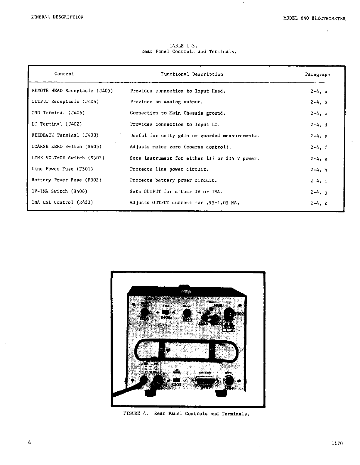
TABLE l-3.
Rear Panel Controls and Terminals.
REMOTE HEAD Receptacle (5405)
OUTPUT Receptacle (5404)
GND Terminal (5406)
LO Terminal (3402)
FEEDBACK Terminal (5403)
COARSE ZERO Switch (S405)
LINE VOLTAGE Switch (S302)
Line Power Fuse (f301)
Battery Power Fuse (F302)
lV-1MA Switch (S406)
IHA CAL Control (R423)
Provides connection to Input Head.
Provides an analog output.
Connection to Main Chassis ground.
Provides connection to Input LO.
Useful for unity gain or guarded measurementa.
Adjusts meter zero (coarse control).
Sets instrument far either 117 or 234 V power.
Protects line power circuit.
Protects battery power circuit.
Sets OUTPUT for either 1V or 1W..
Adjusts OIJTPLW current for .95-1.05 MA.
2-4, a
2-4, b
2-4, c
2-4, d
2-4, e
2-4, f
2-4,
2-4, h
2-4, i
2-4, j
2-4, k
g
FIGURE 4. Rear Panel Controls and Terminals.
4
1170
Page 8

MODEL 640 ELECTROMETER
GENERAL DESCRIPTION
SECTION 2.
2-1.
INPUT CONSIDERATIONS.
Input Head Connections.
a.
Remote Cable. A shielded coaxial cable (5
1.
feet long) is supplied to permit remote location of
the Input Head from the Main Chassis. A” accessory
Model 6401 Cable (25 feet long) also can be used
without degradation of specifications.
2. Mounting.
tom mounted as described in paragraph 2-12.
Input Assembly.
3.
of B” insulated input High terminal (center post)
and a machined housing which is input Low. High in-
put resistance (over 10~6
2 picofarads) is maintained by “se of sapphire in-
sulation.
a.) Custom Connections. The input housing has
been designed to easily adapt for use with ion
chambers and other applications where high input
impedance and low capacitance is required. Dimensions of the input housing are given in Figure 5.
b.) UHF Adapter. The adapter supplied with the
Model 640 is useful when quick connections must
be made using standard UHF cables, However, this
adapter is limited to measurements above lo-l3
ampere or source resistances below lOI4 ohms.
c.) GRg74 (General Radio) Adapter. This accessory adapter is available for use with G&374
Series coaxial accessories. The limitations of
this adapter are similar to those for the UHF
adapter.
b. ~nsulatio”. Use high
riels such as sapphire, teflon, polyethylene or poly-
styrene for insulation of the input circuit.
The Input Head Chassis can be cus-
This assembly (5105) consists
ohms shunted by less than
resistance,
low-loss mate-
OPERATION
NOTE
The input terminal and sapphire insulator
should be protected from contamination so
that the insulation will not be degraded.
Clean, dry connections and cables are very
important to maintain the value of all insulation materials.
tion can be compromised by dust, dirt,
solder, flux, films of oil or water vapor.
A good cleaning agent is methyl alcohol,
which dissolves most common dire without
chemically attacking the insulation.
c. Noise Consideration. The limit of resolution
in voltage and current meaeurements is determined
largely by the noise generated in the source. Stray
low-level noise is present in some form in “early sll
electrical circuits.
guish between stray and signal voltages since it measures the “et voltage.
consider the presence of low-level electrical phenomena such as thermocouples (thermoelectric effect),
flexing of coaxial cables (trioelectric effect),
apparent residual charges on capacitors (die-lectric
absorption), and battery action of two terminals
(gslvanic action).
1. Thermal EMFS.
(thermal emfs) are generated by thermal gradients
between two junctions of dissimilar metals. These
can often be large compared to the signal to be
measured.
To
minimize thg drift caused by thermal
emfs, “se pure copper leads wherever possible in
the source circuit.
m*ine*ining c0**t**t ju*cei0* temperatures especially
by using a large heat sink,“ear the connections.
The Keithley accessory Model 1483 Low Thermal Connection Kit contains all necessary materials for
making very low thermal copper crimp connections for
minimizing thermal effects.
Even the best insula-
The instrument does “ot dtsttn-
When using the microvolt ranges
Thermoelectric potentials
Drift ca” rlso be mL”immLzed by
1170
FIGURE 5.
Dime”sio”s of Input Housing.
2. AC Electric Fields.
The presence of electric
fields generated by power lines or other source8
can have a” effect on instrument operation. AC
voltages which are very large with respect to the
full-scale range sensitivity could drive the ac
amplifier into saturation, thus producing a” erroneous dc output. Proper shielding as described in
paragraph 2-1, d can minimize noise pick-up when
the Fastrument Fa in the presence of large ac fields
or when very sensitive me.ssuremBnta are being made.
3. Magnetic Fields. The presence of strong magnetic fields can be a potential source of BC noise.
Magnetic flux lines which cut a conductor can produce large ac noise especially at power line frequencies. The voltage induced due to magnetic flux
is proportional to the area enclosed by the circuit
as well as the rate of change of magnetic flux. Par
5
Page 9

OPERATION
MODEL
640 ELECTROMETER
example, the motion of a 3-inch diameter loop in the
earth’s magnetic field will induce a signal of several tenths of a microvolt. One way to minimize
magnetic pickup is to arranSe all wiring so that the
loop area enclosed is as small as possible (such as
twisting input leads). A second way to minimize
magnetic pickup is to use shielding aa described in
paragraph 2-1,
d.
d. Shielding.
Electric Fields. Shielding is usually nec-
1.
essary “he” the instrument is in the presence of
very large ac fields or “hen very sensitive measure-
ments are being
ment
circuit and
made.
The shields of the measure-
leads should be connected together
to Sround at only one point. This provides a “tree”
configuration, which minimizes ground loops.
2. Magnetic Fields. Magnetic shielding is useful
where very large magnetic fields are present. Shield-
ing, which is available in the form of plates, foil
or cables, can be used to shield the measuring circuit, the lead wires, or the instrument itself.
e. Moisture.
The Model 640 Inp;t Head is shipped
with a dessicant bag sealed inside. This bag soaks
up the moisture inside the Input Head to insure opti-
mum operation. The dessicant bag, however, will event-
ually become saturated. At this point the Model 640
offset will increase beyond the specified amount.
When this happens take off the bottom cover of the In-
put Head to remove the desaicant bag. Reactivate it
according to the instructions on the bag.
d. FEEDBACK Terminal (51031. This terminal is
used for unity gain or guarded measurements. _
e. DAMPING Control (RlOSl. (Not Shown). This
control permits adjustment of the damping for
INTEGRATE operation.
When the control is set fully
CURRENT
clockwise to “MAX” damping,the rise time is approximately 44 seconds with a 1012 shunt resistor. When
the control ts set fully counter-clockwise to
“MIN”
damping,the rise time corresponds to the critically
damped or CURRENT FAST condition 88 given in the
specifications.
2-3. FRONT PANEL CONTROLS. The front panel controls
are shown in Figures 1 and 2.
The operation of each
control is described 88 follows:
8.
POWER Switch (5301). This switch has four
positions designated AC, OFF, BATTERY, and BATT TEST.
1. AC Position.
This position permits normal
aperacion of the instrument when the power cord is
connected to line power. (The battery charging
circuit operates in this position.)
2. OFF Position.
This position disables both
AC
and BATTERY power to the electrometer circuits except for the battery charging circuit which operates
in this position.
3. BATTERY Position.
normal operation of the
battery
pack
is satisfactorily charged.
This position permits
insteument
when the internal
2-2.
INPLT HEAD CONTROLS AND TESMINALS. The Input
Head is shown in Figures 1 and 3. The operation of
each control or terminal is described aa follows:
a. SHUNT RESISTOR Switch (SlOZ1. This switch selecte 5 positions corresponding to the shunt resistor
(acro88
ment.
and “OPEN”.
input of feedback) require% by the me~8ure.
The switch positions are 10 , lOa, lOlo, 10lz
The “OPEN” position has no resistor
connected.
by 1000 ohms.
c, Input ReceDeecle (JlOSl. This receptacle provides input connection to the Model 640 Input High
and Input Low.
4. BAIT TESTY Position.
This position permits a
check of the battery voltage as indicated by the
meter.
b. FVNCTION Swtich (S4021. This switch has three
positiona designated VOLTAGE,
C”RRENT
INTEGRATE.
CURRENT
FAST, and
1. VOLTAGE Position. This position co,,,,ects the
electrometer .8 8 very sensitive, high impedance
voltmeter with the
SHLMT RESISTORS
connected in
shunt across the input.
2. CDRRENT
FAST.
This position cannects the
electrometer as a feedback pieoammeter which neutralizes the effect of input capacitance and incream response speed.
The SHUNT RESISTORS are
connected in the feedback loop of the amplifier.
3.
CDRRENT INTEGRATE.
This Dosition connects
the 20 picofarad warded caPa&or in the feedback
loop of the ampli ier.
c. RANGE Switch (54031. This switch has thirteen
positions corresponding to full scale voltage sensitivity from 30 microv01ea to 30 volts.
d. METER Swftch (S4041. This switch has 4 poaitions designatad OFF, +, -, and CENTER ZERO.
6
1170
Page 10
SOQEL 640 ELECTROMETER
OPERATION
1. OFF Position.
This position disables the
meter movement to protect against averlaads. This
position has no effect on the OUTPUT voltage when
using a recorder or other instrument.
“i” and ‘I-” Positions. These p0sitiDne select
2.
the polarity af the meter only. The
OUTPUT
voltage
is not affected by these pasitions.
CENTER ZERO. This position sets the meter
3.
circuit so that zero is indicated at center scale
(mid-scale). The deflection of the meter corresponds to one-half RANGE setting, The OUTPUT “oltage is nat affected by this position.
e. ZERO Switch. This switch is a dual-concentric
control.
1. MEDIUM Control (S407). This control is the
cuter knob with eleven pasitions which adjust the
meter-zero.
FINE Confrol (R431). This control is the
2.
inner knob which permits fine meter-zero adjustment.
f. ZERO CHECK (S401). This switch is e normally--
open contact-type switch permitting meter,-zero check.
The ZERO CHECK switch shunts the input HI to input LO
(in voltage function) by 1000 ohms.
ZERO Controls do not provide sufficient range of
CO”tl-01.
g. LINE VOLTAGE Switch (S302). This switch sete
the instrument for either 117 or 234 volt rms linepower. The line-power fuse (F301) should be checked
far proper line voltage rating.
h. Line Power Fuse (F301). This fuse pr~tecee the
power supply circuits when 117-234V line power is
used.
Fuse Racing
117 ”
234 V
1.
Battery Power Fuse (F302). This fuse protects
l/4 smp, 3AG
l/B nmp, 3AG
the power supply circuite when battery power is used.
Fuse rating: 314 amp, 3AG.
j. lv-IMA Switch (5406). This switch sete the
OUTPUT for either 1 volt 0’ 1 mA.
k.
1MA GAL Control (R423). This control permits
adjustment of the
OUTPUT
(with lV-1MA Switch set co
1MA) over the range 0.95 to 1.05 mA.
2-5.
OPERATING CONSIDERATIONS.
REAR PANEL CONTROLS AND TERMINALS. The rear
2-4.
panel controls and terminals sre shown in Figure 4.
The operation of each control or terminal is described
as follows.
a. REMOTE HEAD Receptacle (5405). This receptacle
is a 24-pin cOnnector (Amphenol 57-40240) which mates
with the interconnecting cable between the Main Chas-
is and Input Head (Remote Head). Two “echenical re-
taining clips see provided on the receptacle to Secure
the mating plug (P405).
b.
OUTPUT
Receptacle (5404). This connector pro-
vides en analog output far recording or monitaring
pUrpOSeS. The output is 11 volt at up to 1 “A for
full scale input.
the input palarity.
The output polarity is ~posite
The front panel METER switch has
n0 effect on the polarity of the analog output.
c. GND Terminal (54061. This terminal is connected
to Main Chassis ground and the outside shell of con-
neceor 5405.
With no cOnnection between GND and LO
(shorting link removed), the INPUT LO to Main Chassis
ground isolation is greaterthan 109 : shunted by .05
microfarad,
d. LO Terminal (5402). This terminal is connected
to INPUT LO on INPUT HEAD.
e. FEEDBACK Terminal (5403).
This
terminal is
used for unity gain or guarded measurements. The
terminal (5403) on the Main Chassis is connected to
5103 an the INPuT HEAD by way of the remote cable.
f. COARSE ZERO Switch (5405). This switch hes ten
positions far adjusting the meter-zero circuit. This
switch should only be used when the FINE and MEDIUM
a. Mode of Opereeion.
1. AC Line-Power.
The Model 640 can be operated
using ac line-power at 117V or 234V, 50 .x 60 Hz.
To operete,set LINE VOLTAGE Switch (5302) to 117
or 234, check for proper rated fuse (F301), and
connect the line cord.
Set the POWER Switch (S301)
to “AC” operation.
2. Battery Power.
The Model 640 can be operated
using battery paver supplied by e rechargeable 6-
volt nickel-cadmium battery peck.
a.) To check the battery charge, set the POWER
Switch to “&ATT TEST” position. The meter should
indicate +6V or greeter if charge is sstisfactary.
b.) To recharge the battery pack, connect the
p,yF;z cord to ec power. Set the POWER Switch to
. (The bettery will automatically recharge
when the POWER Switch is in either “AC” or “OFF”
positians).
Battei-y charging-time is approximately 16 hours for full charge after 8 hours of
continuous we.
3. AC Co Battery Switching. The Model 640 ten
be modified so that it will sutomsticallv switch
fro” “AC” operatia t0 “BATTERY” ~peraeibn if the
line power fails.
An explanation of this modifica-
tion is given in paragraph 3-4 in the Circuit Des-
cription section.
b. Warm-UC. If the
instrument
is to be used for
very sensitive measurements,allaw the instrument to
stabilize far an haur or more. The POWER Switch can
be see et either ‘AC” or “BATTERY”.
1170 7
Page 11

OPERATION
MODEL 640 ELECTROMETER
C. Meter zero.
The meter zero circuit utilizes
three conerols PINE, MEDIUM, and COARSE.
1.
After
warm-up, set the METER Switch to CENTER
ZERO.
2. Adjust the MEDIUM ZERO Control for center-
zero meter position.
(The rear panel COARSE ZERO
Switch can be used tf meter reads off scale).
3. Increase sensitivity using the RANGE Switch
and adjust the
FINE
ZERO Control for center-zero
meter indication.
2-h.
VOLTAGE FUNCTION.
a. General.
When the FUNCTION Switch is set to the
VOLTAGE poaition,the Model 640 operates as a high in-
put-impedance electrometer.
The
b. Input Impedance.16
input resistance (HI to
LO) is greater than 10 ohms shunted by less than 2
picofarads. This specification is valid 2 for the
SHUNT RESISTOR Switch sat to “OPEN” with no depreda-
tion of the input HI to input M insulation. ?‘he input resistance can be lowered by se~~ti”gl~lWNUN~RE-
SISTOR
values in four steps from 10 to 10 ,
c. Microvoltmeter Measurements.
1. Theory. The electrometer, when used as a
microvoltmeter, can be illustrated 88 shown in
Figure 6.
In this configuration the instrument is
useful for making sensitive measurements from 30
microvolts full scale to 30 volts. The sensitivity
is adjusted by the RANGE Switch (5403) represented
by RA.
wltage eA is defined by the following expression,
The input voltage is represented by ei.
The
eA = ei (j&)
where K is the amplifier loop gain.
Therefore iA = *A 2 ei where KA is selected by
the RANGE Switch (S403).
XK
2. Voltage “easurement.
a.) High Impedance. Although the electrometer
has a very high input impedance, the useability
of the Model 640 as a micravoltmeter is limited
by the thermal (Johnson) noise generated in the
m impedance.
Refer to paragraph 2-10 for a
complete discussion of thermal notae.
b.) Low Impedance.
The Model 640 can be used
on the more sensitive ranges by setting the SHUNT
RESISTOR Switch to 1012 ohms or lower. The laad-
ing effects should be considered when measuring
high source-impedance.
3. Current Measurement. The Model 640 can be
used for current measurements since the microvolt-
meter measures the volta e ac
resistor selected for 10 , 10 , 1010, or 1012 ohms.
088 a known shunt
k; li
Current can be calculated by the ratio of voltage
reading to shunt resistance. “se this technique
where low noise is important,alehough faster re-
sponse is provided by setting the FUNCTION Switch
to CURRENT FAST as described in paragraph 2-7.
4. Unity Gain Meesurements. The Model 640 can
be used for measuring a potential from B very high
impedance source with .025% accuracy. Connect a
digital voltmeter (or differential) to FEEDBACK and
LO terminals as shown in Figure 7.
SOURCE
VOL’UGE
FEEDBACK -
(INPUT
HEAD)
FIGURE 6. Voltage Function With Shunt Resistor KS
< FEEDBACK
(MAIN CHASSIS)
Page 12
MODEL 640 ELECTROMETER
-
INPUT
OPERATION
LO
FIGURE 7.
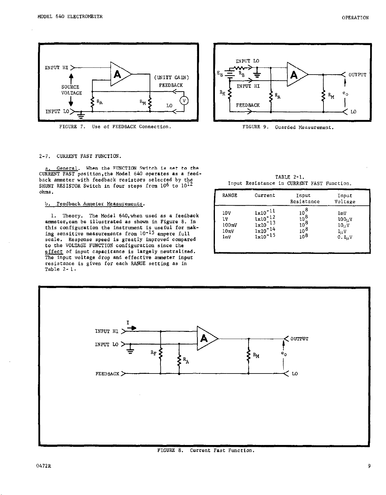
CURRENT FAST FUNCTION.
2-7.
a. General.
CURRENT FAST
“se Of FEEDBACK Connection.
When the FUNCTION Switch is set to the
position,the Model 640 operates es e feedback ammeter with feedback resistors selected by the
SHUNT RESISTOR Switch in four steps from 106 to 1012
ohms.
b. Feedback Aonoeter Measurements.
1. Theory.
The Model 640,when used 8s e feedback
amm?ter,cen be illustrated 88 shown in Figure 8. In
this configuration the instrument is useful for mek-
ing sensitive meesurements from lo-l5 ampere full
scale. Response speed is greatly improved compared
to the VOLTAGE FUNCTION configuration since the
effect of input capacitance is largely neutralized.
The input voltage drop end effective ameter input
resistance is given for each RANGE setting es in
Table 2- 1.
TABLE 2-1.
Inwt Resiacance in CURRENT FAST Function.
RANGE
Current Input
Resistance
1ov 1x10-11
1V
;;:;I$
1OOmV
1OmV
lmv
:g: ::
108
108
108
108
108 O.lvV
Input
Voltage
lmv
1OO~V
1ovv
4Jv
c
0472B
INPUT HI >-+
INPUT LO >
FEEDBACK >
I
I
5
RF
RM
( OUTPUT
t
a0
I
< LO
FIGURE 8.
Current Feet Function.
Page 13

OPERATION
MODEL 640 ELECTROMETER
2. Current
e.) Rise Time.
particular meeeuremene depends on the shunt resistor end residual capacitance ecroes the feedbeck loop.
is given in the specifications for each resistor
value.
stcondition where no external capacitance is
cannected between the FEEDBACK terminal end u
ix
b.) Guarded Measurements. The Model 640 ten
be used for guarded resistance measurements using
the FEEDBACK Terminal and Input HI connections 89
shown in Figure 9. Since EB and RB develop e
known current IB,then the electrometer will indicate the voltege develaped ecrose Rx (un!aowo
resistance).
Rx
CURRRNT INTEGRATE FUNCTION.
2-8.
a. General.
CURRENT INTEGRATE position the Model 640 operates es
e feedback ammeter with damping.
b. Feedback Ammeter Measurements.
1. Theory.
trated es shown in Figure 10. In this configuration
the DAMPING Control is set te WAX” position so thet
a 20 pf cepecitence is connected in the feedback
loop (SHWT RESISTOR Switch set t0 “OPEN”). The
current measured is determined by the following
equation,
Measurement.
The actual rise time for a
The specified rise time (10 to 90%)
These rise times era for a criticallv
, Additional external capacitance ten be
= Eo =
T
When the FUNCTION Switch is eat ta the
The Model 640 operation ten be illus-
%K RB
2-9.
use as en smueter accurate to 20.25%.
10 ) shunt resistors can be accomplished using a
current integrating technique.
voleege eource can be connected in series with the
shunt resistor forming e current source where I =
V/R.
the meter reading EM is e function af cepacitance C
end the integral of the current.
arAEM =
Solving for R,
Where R -
Since the eccuracy of C is +.25% the overall eccurecy
af the calibration will depend on the accurecies of
the voltage swrce V, the meter accuracy EM, end the
time accuracy T.
acy, maesure the enalog OUTPUT using a 0.01% digitel
voltmeter.) Refer to Figure 11 for circuit connec-
tions.
SHUNT RESISTOR CALIBRATION.
8. General. The Model 640 ten be calibrated for
& Theory. Calibration of
With FUNCTION Switch set t0 CURRENT INTEGRATE
c J
$ AT =(!-) AT
shunt resistance, ohms.
V
= eource voltage.
C = integrsting capacitor (20 pf).
E-E0 - chenge in wltage indication.
T-T0 = time ineervel for voltage change.
(To obtain the best possible eccur-
c. Calibretion Procedure.
1. Set the FUNCTION Switch to CURRENT?NTZGRATE.
rhe
high value (lo”,
An
accurately known
where I =
AE
At
2. Variable Damping.
(R108) is adjusted.counter-clockwise,the Model 640
can be used fot current meesuremente with veriable
damping.
10
cm-rent in amperes.
C = feedback capacitance (2 x 10-11).
=
change in the meter resdtng during time
interval
=
time interval of me*aurement.
At.
When the DAMPING Control
2. Set the DAMPING to ‘WAX”.
3. Apply the voltage source between P106 end
input LO. (Remove the Input Heed bottom cover for
access).
4. Zero meter.
5. Select lOlo or 1012 SHUNT RESISTOR.
6. Measure time interval from zero to full scale
an the meter.
7. Calculste the value of R using equation.
Record time interval T-To.
04728
Page 14

MODEL 640 ELECTROMETER OPERATION
INPUT HI
< OUTPUT OUTPUT
INPUT LO
<
1
e. =
l/C
I
LLO LO
--c
FEEDBACK,
>
!
RI.!
1
I
p+k
E -
-
FEEDSACK~
P106
INPUT HI
FIGURE 10.
Equivalent Current Integrator.
-< OUTPUT
RA,
% *o
t
= l/C J E/R dt
‘< Lo
04728
FIGURE 11. Current Integrate - Shunt Resistor Calibration.
11
Page 15

OPERATION
MODEL 640 ELECTROMETER
Z-10.
ANALOG OUTPUTS.
a. OlPPPUT
en analog output for recording or monitoring purposes.
eo161”~“,~i?&,,
full scale input. The-polarity of the output is
opposite the input signal.
Gain: 0.033 eo 3.3 x 10⁴
Frequency Response (Within 3 db): dc to 0.07 cps
at a
of 10
Noise: Below lcps: seme es meter noise for spec-
ified function. Above 1 cp8:
output p-p an the 30-v to lo-mv ranges, increasing
co 10% an the 1-w and lower ranges.
dtit~ the o”tp”t is approximately 1X4 for a full
scale input.
b. onio Gain output.
set to VOLTAGE the FEEDBACK terminal can be used for
measuring a potential from a very high impedance
SO”X.2.
in .01X or 10 M”, exclusive of zero drift, for output
current of 100 pA or less.
Terminal
P
ain of 3.3 x 10 , rising to 35 cps at e gain
3
or below.
1MA Output. With the IV-1”A Switch set to
At dc, the output is equal to the input with-
(54041. This terminal provides
With the l”-WA SWitch (S406) set
is + 1 volt corresponding to a
less than 2% of full
When the FUNCTION Switch is
The peak-to-Peak noise is approximately five times the
rms value (from experimental measurements), therefore
the equation can be expressed as follows.
EPP =
If the ambient temPerat”re is 300°K (room ambient)
then the peak-peak noise can be expressed as follows.
EPP =
C. Typical Example. The Peak-peak thermal noise
generated in an ideal so”rce resistance can be illus-
trated as follows.
Given: Amplifier BandwidthAF = 0.08 *
EPP (typically)
KPP =
*AF =
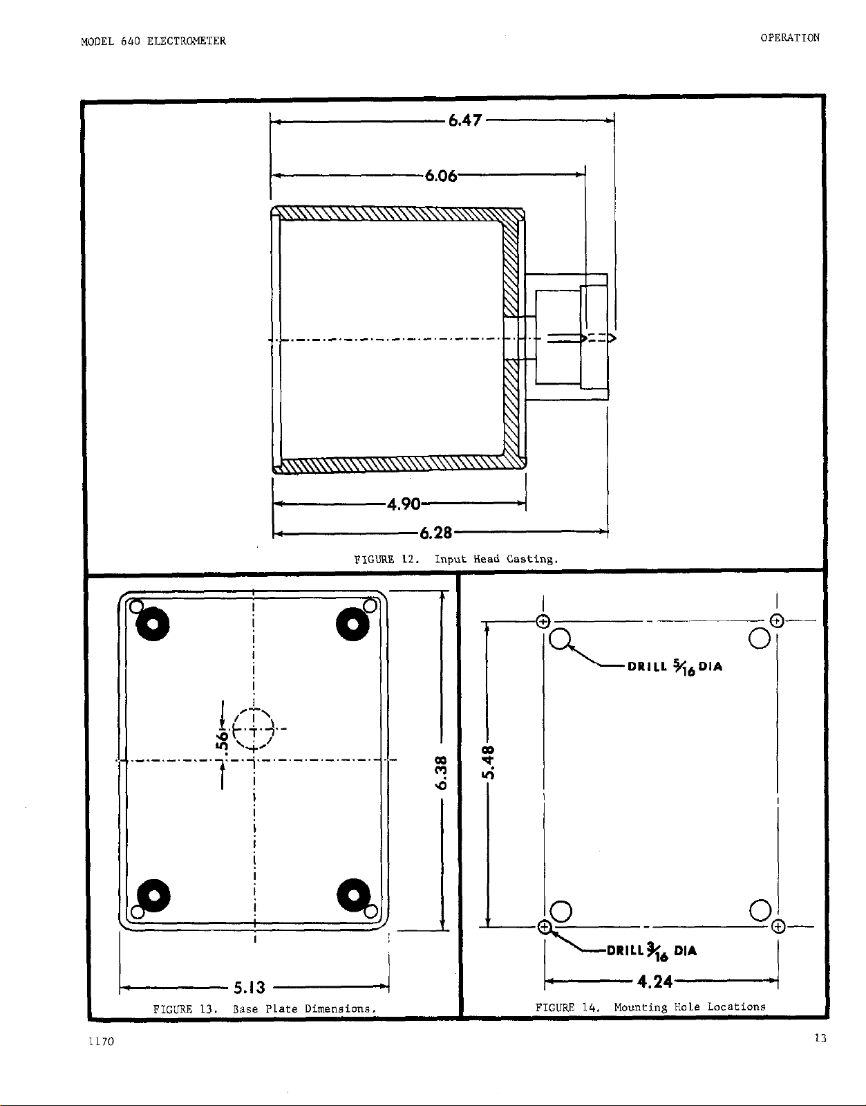
2-12.
8. casting Dimensions.
the Input Head Casting are shown in Figures 12 and
13.
5 x %ms
6.45 x 1O-Lo s
R - 1012 ohms.
RANGE see to 1 MY.
180 vV Peak-Peak
= 6.45 x lo-lo
1
kiK=
MOUNTING DIMENSIONS.
2% lo’& 2 x lo-‘f 2 .OB
The overall dimensions of
2-11. THERMAL NOISE.
e. General. A common limitation of microvoltmeter
measurements from high so”rce impedances is the eherm-
al noise (Johnson noise) generated in the source.
b. Theory. Thermal noise in an w resistance
can be theoretically determined from
noise equation as follows.
%m =
JZXZ
the
Johnson
where
Q-m =
T =
R =
F = amplifier bandwidth, Hz.
K =
rm8 voltage noise generated in the
resistence.
temperature, OK.
ideal resistance, ohms.
soltzmenn CO*Ste”t (1.38 x 10⁻¹ojaulea/4()
b.
Input
loaded with the dimensions from the base 8s shawn in
Figure 12.
c, “auntinn the Base Plate. The Base Plate can be
mounted on a machined surface for custom installation
of the Input Head.
Input Head casting using four type 6-32 x l/4 BCTBWS.
The rubber feet are’attached to the base plate “sing
type 6-32 x l/2 Phillips Heed screws and mating #6
kep nuts.
this hardware).
Casting to e surface Plate.clearance holes must be
drilled in the surface plate as shawn in Figure 14.
The Casting can be fastened to the surface using type
6-32 screwe.
the four 8crews replaced.
ed should provide sufficient clearance for the 6-32
Phillips screw heeds.)
contact. The input COntaCt is spring
The Base Plate is fastened Co the
(The deesicant beg is also attached “sing
In order to mount the Input Head
The rubber feet should be removed and
(Note that the holes drill-
12
04728
Page 16
MODEL 640 ELECTR‘WSTER
1
.I ._.-._.-.-.
:-.i,-‘-‘-‘-‘-‘-.-’
1 i
i
I
i
I
I
FIGURE 12.
6.28
>ut Head Castins.
I”1
4
L5.13 I
FIGURE 13.
1170
Base Plate Dimensions, FIGURE 14.
Mounting Hole Locations
Page 17

CIRCUIT DESCRIPTION
MODEL 640 ELECTROMETER
SECTION 3.
3-l. GENERAL.
Head (Remote Preamplifier) end e Main Chassis (Amplifier end Power Supply).
8. High Impedance Microvoltmeter. When the FLNCTION Switch is set to VOLTAGE,the Model 640 operates
as e very sensitive, stable voltmeter with very high
input Lmpedance .
b. Vibrating Capacitor Electrometer. When the
FUNCTION
Model 640 operates es a stable current enh charge
measuring instrument.
3-2.
amplifier utilizes e vibrating-capacitor input preamplifier end variable-sensitivity emplifier. The
overall amplifier operates es a very sensitive dc
amplifier using e vibrating cepecitor es en input
signal modulator.
amplified end demodulated in the preamplifier circuit.
The dc signal is filtered end amplified further
by the main dc amplifier.
ly to provide gain accuracy end stability, A block
diagram of the overall amplifier is shown in Figure 15.
3-3. INPm HEAD.
Heed contains the input modulator, high-gain ec emplifier, oscillator end demodulator. The Shunt Resistors are connected across the overall amplifierfeedbeck using Switch S102.
Switch is set to either CURRENT position,the
ELECTROMETER AMPLIFIER. The basic electrometer
The Model 640 is composed of an Input
The input signal is modulated,
Feedback is used extensive-
(Remote Preamplifier). The Input
CIRCUIT DESCRIPTION
a. Vibrating Capacitor.
used consisting of two stationary pletes and e vibrating membrane which is excited et e carrier frequency
of approximately 400 kHz. The glass membrane has de-
posited metal surfaces and is sealed in en evacuated
glass “bottle”.
high input-impedance end low drift. When driven et
the carrier frequency (under proper canditions),the
membrane resonates et approximately 6000 Hertz. Since
the carrier (drive) frequency is much higher then the
resonenC
ics does not appreciably effect the amplifier circuit.
b.
to receuescle 5105
is isolated from Main Chassis ground. A 10 megohm
resistor (RIOS) prevents e rapid discharge of the
vibrating capacitor beck ineo the source circuit. The
modulated signal is applied to the first stage ac
amplifier through e guerded, three-terminal air capacitor. (Cl05 which is 20 pF 5 0.25%).
c.
a normally-open control which energizes solenoid RlOl.
When KlOl is energized,a cancect connects input High
to FEEDBACK through a 1000 ohm resistor. The input
source end vibrating cspecitor remain connected in
the circuit during zero check. A loading error will
result in the meter zero reading if the source resistence (RS) is less then 100 K in accordance with the
following equation.
% Error = 100
frequency, the terrier frequency end harmon-
Input circuit. The input High signal is spplied
Zero Check Circuit. The ZERO CHECK control is
RS’1’
This unique capacitor provides very
on
where KS is expressed in kilohms.
A
special capacitor is
the Inwe Heed. The inout LO
r-
-INPUT HEAD -MAIN CHASSIS -INPUT HEAD -MAIN CHASSIS
FEEDBACK FEEDBACK
INPUT INPUT
FIGURE 15. Block Diagram of Model 640
14
1170
Page 18

MODEL 640 El.ECTROMETER
CIRCUIT DESCKIPTION
d. AC Amplifier,
The ac amplifier provides very
high gain through the use of a two-stage amplifier
and a phase splitter amplifier. A" FET (QlOl) provides a high input impedance. A" emitter-follower
stage (transistor Ql02) provfdes impedance matching
between QlOl and transistor Q106. Transistors Q103
9104, Q105 and QlOS are switches providing gain ad-
jwtment to prevent oscillation on the higher ranges.
Transistors Q107, Q109 and QllO form a second stage
ac amplifier. A phase splitter circuit is formed by
transistors Qlll and Q112. A tuned circuit composed
of integ. ckt. QAlOl, inductor LlOl and trimmer cap-
acitor Cl24 provide attenuation of carrier frequency
(6000 Hz) second harmonic noise. The ac signal is
synchronously demodulated by transistors 4506 and
Q507 (locatad in the oscillator circuit).
e. Oscillator Circuit. The high frequency drive
(400 kHz) signal is generated by a tuned circuit consisting of transformer T501, capacitors c502, c503
and C504 and transistor Q501. Capacitor C502 adjusts
the 400 kHz carrier frequency. Pote"tiometer R506
adjusts the gain of the drive circuit. The drive o"tput is developed across transformer T502 and capacitor
C509 to excite vibrating capacitor plates (pins 1 and
The actual signal is a modulated "envelope" as
4).
shown in Figure 28 in Section 6. FET Q503 and inte-
grated circuit QA501 form a wave-shaping circuit far
phase and syrranetry control.
Integrated circuit QA502
is part of a phase control circuit for the demodulator
autput. Potentiometer R517 adjusts the phase of the
demodulator drive. Integrated circuit QA503 is part
of a swmletry control circuit.
Potentiometee S.521
adjusts the hemodulator a" and off times (syrmnetry).
Transistor 9505 controls the switching of demodulat-
ing transistors Q506 and Q507.
3-4. MAIN CHASSIS.
The Main Chassis contains a dc
amplifier circuit, meter circuit, sensitivity switching circuit, power supply circuit, and battery charg-
ing circuit 88 shown on Schematic 213833.
a. DC Amplifier.
A differential input stage is
formed by FET's Q401 and Q402 and transistors Q403
and Q404.
balance.
Potentiometer R404 provides dc amplifier
Capacitors C401, C402, and C403 provide
filtering of the demodulator ripple. FET Q405 and
transistors Q406 and Q409 (Darlingto" amplifier) pro-
vide additional gain for driving the meter circuit
and analog O"TPUT.
Transistor Q4OS provides current
limiting when the output is overloaded. Transistor
4407 provides a constant current for biasing purposes.
b. Meter Circuit.
The meter circuit consists of a
meter switch 5404, a 1-W meter movement (M401), and
various meter circuit adjustments. The Meter switch
has a" OFF position (which shorts o"t the meter movement), "t" and 11-11
polarity positions (which connect
the meter for either positive 01: negative deflection),
and a ZERO CENTER position (which biases the meter
such that center scale represents zero).
POtf?"tiOmeter R421 is an internal adjustment of the ZERO
CENTER meter bias current. Pote"tiameter R455 is an
internal adjustment of the meter calibration.
c. Zero Controls.
Switch,5405 is B COARSE ZERO
adjustment which can select up to 11 positions a" a
divider string (resistors R432 thtough R442). Switch
S407 is a~MSDILIM ZERO adjustment which can select up
to 11 positions a" a divider strinn (resistors R443
through R452).
Potentiometer R431-is a FINE ZERO
adjustment.
1170
Page 19

CIRCUIT DESCRIPTION
d. Sensitivity Switching. SANGE Switch 5403 has
13 positions which connect resistors R457 through
R469.
The range resistors determine the voltmeter
gain or sensitivity from 30 microvolts to 30 volts
full scale.
Power Supply, (As shown on Schematic 213823).
a.
The power for the Model 640 is provided by either a
rechargeable 6-volt battery pack or a recitifier cir-
cuit
operated by 50-60 Hz line power.
S301 selects four positions: “AC” (line power),
Power Switch
“OFF”,
“BATT” (battery power) and “SATT TEST” (battery voltage check).
The power supply utilizes a -6 volt unregulated voltage from the battery pack or a rectifier
circuit composed of transformer T303 secondary (yellow
end green taps) and diodes X317-D318. A 5-volt regu-
later is composed ofcapacitor C321, transistors Q317-
Q319 (Darlington series regulator), and reference
diode D319. Transistors 9321 and Q322 compoee an output sensing amplifier to regulate the series transistor
stage.
Potentiometer R338 is a.” internal adjustment
of the regulated output (approximately -5 volts). The
regulated voltage is applied to an Inverter circuit
consisting of transistors Q301-Q302 end saturable core
transformer T301.
MODEL 640 ELECTROMETER
Line Power to Battery Switching. The Model
5.
640 can be modified so that a failure of line power
(with POWER Switch set to
“AC”)
will ca”se an automatic switching to battery operation to occur. A
diode
(0.75A. 5OV,
Keithley Part No. RF-17) can be
connected at the POWER Switch 88 shown in Figure
When line power is present the diode is turned off
and the battery is not used.
f. Battery Charuinp. Circuit. The charging circuit
functions whenever the POWER switch is eet to “AC”
or “OFF”.
Charging c”rrent is provided
by a
rectifier circuit conslating of diodes 0315-0316 and resi*tor 107.9. Fuse F302 is rated for 314 ampere and
used to protect the battery end circuitry during
charging or discharging.
+ 4OV Supply. Power is tapped from B second-
1.
ary winding on Craneformer T302 (brown/yellow,
brown/white, brown). Diodes D301-0304 and capact-
tars C302-C303 provide + 40 volts for the dc ampli-
fier output stage.
- 2ov supply.
2.
This voltage is not used in
the Model 640.
+ 12” supply. Power is tapped from B eecand-
3.
ary winding
on
transformer T302 (red/yellow, yellow/
white, yellow). Diodes 0307-0310, resistor R304,
and capacitor C307 form a rectifier circuit. A
voltage doubling circuit cdnsisting of capacitors
C305-C306, and diodes D30S-D309 forms a bootstrap
voltage).
Transistors Q303-Q304 form a Darlington
series regulator circuit. Feedback is obtained by
sampling the + and - 12 volt outputs at the junction
of resistors R316 and R317. Transistors Q30S and
Q309 form a differential amplifier which senses a
change in either the + or - outputs. Another dif-
ferential pair (transistors Q306-Q307) drives the
base of transistor 9304 to complete the feedback
100p.
Transistor Q305 provides overload-current
protection by sensing the current through resistor
R305.
-12v Supply. Power is tapped from a aecond-
4.
ary winding on transformer T302 (red, blue/ white,
blue). Diodes D311-0312, resistor R318, and capacitor form a rectifier circuit. Transistors Q310Q311 form e Darlington series regulator circuit.
Feedback is obtained by sampling the -12 volt out-
put et the wiper erm of potentiometer R327. This
potentiometer adjusts the output voltage. Transistors Q114-Q115 form a differential amplifier with
the base of Q314 referenced to diode D314. Transistor 9313 drives the base of Q310 to series regulate the output. Transistor Q312 provides overload
current protection by sensing the current through
resistar R345.
FROM BATTERY
I
FIGURE 17. Line to Battery Switching.
3-5.
VOLTAGE FUNCTION.
set to “VOLTAGE”, the Model 640 operates as a sensitive voltmeter with input “OPEN” or shunted by any
one of four resistors,RlOl through R104.
3-6.
CURRENT FAST FUNCTION.
eet to “CDRRENT FAST”, the Model 640 operates as e
feedback ammeter with a Shunt Resistor connected
acrose the amplifier (from High to Feedback). An
external resistance can be connected ,in place of the
four Shunt Resistors “he,, switch 5102 ie *et to “OPEN”.
This
method minimizes the slowing effect of capacit-
ance across the input.
3-7. CURRENT INTEGRATE
Switch set to “CURRENT INTF.GRATE”,the Model 640
operates ee a feedbaok anmeter or coulomb-meter.
With (1 Shunt Resistor connected,(RlOl through R104)
a 20 pF capacitor (ClO5) shunte the amplifier to
therefore slow the response and filteenoisy signals.
With switch S102 set to “OPEN”,capacitor Cl05 acts
as an integrating capacitor for charge or current
integration measurements. A simplified diagrams of
the current integration amplifier is shown in Figure
11 . When the
INTFJXATE”, switch S4O2 connects -5 volts to
FUNCTION Switch is set to “CURRENT
K102 which in turn closes e contact.
connecte the Damping Control (RlOS) such that Capac-
itor Cl05 is connected in the feedback loop. The
Damping Control adjusts the effective capacitance
connected in the feedback loop and thus controls the
amount of damping. When the Damping Control is ad-
justed fully clockwise the maximum damping (20 pF
+ .25%)
is provided.
With the FUNCTION Switch
With the FUNCTION Switch
FUNCTION.
With the FUNCTION
solenoid
The contact
16
1170
Page 20

MOOEL 640 ELECTROMETER
ACCESSORIES
SECTION 4. ACCESSORIES
4-1. GENERAL.
The follo"ing Keithlsy accessories
can be used with the Model 640 to provide additional
convenience and versatility.
Model 6401 Remote Cable
Description:
The Model 6401 is a shielded coaxial cable with a
Keithley B-195 (male) connector on each end. The
cable is 25 feet long.
Model
Description:
The Model
6402 is
special adapter which replaces the
UHF adapter supplied with the instrument.
Application:
The Model 6402 adapts the Input Receptacle for GR074
series Of coaxial accessories. (General Radio Co.).
This adapter is limited to measurements above
10
-13
amperes or source resistances belo” 1014 ohms. The
adapter can be connected to the Input Head as shown
in the illustration.
4-2. OPERATING INSTRUCTIONS. A separate Ins~ructio"
Manual is supplied with each accessory giving com-
p1ete operating information.
Application:
The Model
6401 permits remote location
Head up to 25 feet from the Main Chassis with no degradation to the specifications.
6402
Adqter
of the Input
Model 399 Isolating Amplifier
Description:
The Model 399 is a unity-gain amplifier which permits
operation with the instrument output floated at up to
1500 volts off ground while the Model 399 output is
grounded or floated up to 100 volts off ground.
1170
Application:
The M,,del 399 can be used for ‘FIFO” operation (float-
ing input, floating output) or when it is necessary
ea break ground loops within a system. The 1 volt at
up to 1 mA output enables use of the Model 399 as a
preamp far driving most analog recorders.
Page 21

ACCESSORIES
Specifications:
MODEL 640 ELECTROMETER
Model 399 Isolating Amplifier (Cant’d.)
GAIN: XI, adjustable 23%.
GAIN ACCIJRACY :
GAIN LINEARITY:
,o,za (as set ae factory).
Within 3 millivolts for signal levels
below I volt.
FREQUENCY RESPONSE (minimum): Fast: dc to 100 Hz
(-3 dB); Slow: dc to 0.3 He (-3 dB).
NOISE: Less than 5 millivolts p-p, .Ol Hz to lk”z;*
less than 0.5 millivolt p-p, .Ol Hz to 0.35 HZ.*
ZERO STABILITY: Setter than 3 millivolts/24 hours at
reasansblv constant ambient temperature.
106
INPOT RESIS+ANCE:
INPUT OFFSET CURRENT:
FULL-SCALE INPUT:
ohms.
mess than
lo-6
ampere.
11 volt with 100% overrange.
MAXIMUM INPUT OVERLOAD: 100 volts.
INPO’I ISOLATION: Greater than 101’ ohms at 50% rela-
tive humdiity and 2PC shunted by less than 100
picofarads.
MAXIMUM COMMON MODE VOLTAGE: 1500 volts peak, dc or
ac.
CMRR: Greater than 120 dS at dc, greater than 100 dB
up to 1 kHz.
OOTPUT :
+l volt at up to 1 milliampere, 100% over-
range.
OUTPUT ISOl.4TION:
Greater than lo* ohms shunted by
less than 0.001 microfarad.
POWER :
105-125 ar 210-250 volts (switch selected),
SO-60 Hz, 5 watts.
DIMENSIONS, WEIGHT:
4-112” high x 4-112” wide x 7”
deep (11 cm x 11 cm x 18 cm); “et weight, 3 pounds
(1.3 kg).
ACCESSORIES PURNISHED:
Model 3991 Input Cable
(to
safely mate Model 399
to most Keithley instruments).
xModulation suikes a few hundredths of B volt D-D
at a IO-kliz. ;ep-rate may be observed with widebind
SyStmS*
Model 370 Recorder
rlescription:
The Model 370
is compatible
is a compact, paper chart recorder which
with most Keithley instruments having a
1 volt; 1 milliampere output.
Application:
The
Model 370 can be used for analog recording applications with inputs floated at up to 500 volts off
ground.
The Model 3701 Input Cable supplied permits
convenient connections to the instrument.
18
1170
Page 22

MODEL 640 ELECTROMETER
ACCESSORIES
Model 4006 Reck Mounting Kit
Description:
The Model 4006 is a rack mounting kit with overall
dimensions, 7 inches high x 19 inches wide. Two top
covers are provided for use with either 10 inch or
13 inch deep instruments.
Application:
The Model 4006 converts the lnetrur,,ent from bench
mounting to rack mounting.
It is suitable for mount-
ing one instrument in one-half of a standard 19-inch
rack.
Pares List:
Item
NO.
OescripCion
1 Top Cover, 10”
2 Panel Adapter Plate
3 Angle Support
4 screw, 1110 x 3/S”
5 connecting Plate
6 screw, ii10 x l/2”
7 Angle
8 Top Cover, 13”
Qcy. Per
Assembly
1
1
1
4
1
4
1
1
Keithley
Pare NO.
200168
19158A
19157A
--19154A
___
191478
200158
Model 4007 Rack Mounting Kit
Description:
The Model 4007 is a rack mounting kit with overall
dimensions, 7 inches high x 19 inches wide. Two top
covers are provided for use with either 10 inch or
13 inch deep instruments.
Application:
The Model 4007 con”erts the instrument from bench
mounting to rack mounting.
It is suitable for mount-
ing two instruments in a standard 19-inch rack.
1170
Parts List:
Item
NO.
Oe.SCriptiO” Assembly Part NO.
1 Top cwer, 10”
screw, n10 x l/2”
4
5 COnneceing Plats
6 screw, ii10 x l/Z”
7 Angle
8 Top Cover, 13”
9 Zee Bracket
10 Plate
Qty. Per
2 200168
s
1 19154A
4 --2 141478
2 200158
1 19167A
1 19700‘4
Keithley
_--
19
Page 23

SERVICING
MODEL 640 ELECTROMETER
SECTION 5.
GENERAL. This section contains procedures for
5-l.
checkout and servicing the instrument.
step-by-step procedures for complete servicing.
SERVICING SCHEDULE. This instrument requires
5-2.
no periodic msintenance
beyond the normal care re-
quired for high-quality electronic equipment.
PARTS KEPLACmT. Refer to the Replaceable
5-3.
parts diet, Section 7, for information regarding corn-
ponent specifications end part numbers.
ponents as indicated using replacement parts which
meet the listed specifications.
Code
etter Instrument Type
Follow the
Replace com-
TABLE 5-l.
Test Equipment.
Specificetion
SEWICiNG
5-4. TROWLESHOOTING.
Test Equipment.
a..
mended test equipment for servicing end calibrating
this instrument.
b. Troubleshootina Guide. Refer to Table 5-2 for
e brief outline of troubleshooting hints. The Table
identifies the Symptoms or Trouble, the Probable
Cause, and the suggested Solution.
If the instrument problem cannot be readily
located or repaired, contact a Keithley representative or the Sales Service Department,
Cleveland, Ohio.
Manufacturer
and Model No.
Refer to Table 5-l for recom-
NOTE
“Se
A
High Voltage Supply
B Nanovolt Source
c
D
E
F
Picoampere Source 10-4 to lo-14A
Megohnrmeter
Differential Voltmeter 1OOmV - 5OOV, .Ol%
Digital Voltmeter
G Function Generator
H
I
J
Oscilloscope
Probes; 1O:l & 1:l
Capacitance Bridge
K “eriable Transformer
& Power Line Meter
L Recorder
o-lOOOV, .01-V steps,
10-10 to 1v
, .25 to .75% accuracy.
.05% accuracy.
, .25 to .l% accuracy.
lo7 to lo13 ohms 220% accuracy.
1wv to lOOOV, 0.1%
1mA sensitivity: .05 8 Rise Time
lo-90%
Keithley, Model 241
Keithley, Model 260
Keithley, Model 261
Keiehley, Model 500
Accuracy checks.
Accuracy checks.
Accuracy checks.
ISOlatio” Resist
ante Check.
Keithley, Model 662
Keithley, Model 163
Wavecek, Type 110
Accuracy checks.
Trouble-shooting
Frequency Respon
Check.
Tektronix 503/5blA
Trouble-shooting
Calibration.
Tektronix
Use with Oscillo
scope.
Generel Radio 1blbA
Variac/RCA
Capacitor checks
Power Supply
Calibration.
Keiehley, Model 370 Drift end Noise
Checks.
20
1170
Page 24

MODEL 640 ELECTROMETER
symptom or Trouble
Probable Cause
TABLE 5-2.
Troubleshaming Guide
SOlUti.3”
SERVICING
Sub-
Assembly Figure
kcessive Voltage Drift
ixcessive Noise at
~UTPIJT or Meter
!xcessive current >ffset or drift
eter Pegs Off-Scale
(all ranges)
DC Amplifier
Vibrating Capacitor
Input PET (QlOl)
Vibrating Capacitor
Defective Insulaeio”
Excessive Humidity
Vibrating capacitor
Power Supplies
AC Amplifier
Oacillatar Circuit
Power Supplies
Replace V.C. (C121).
Check diodes 0405-6 and potentiometer R431.
Replace V.C. (C121).
Replace PET (QlOl).
Replace V.C. (C121).
Check sapphire insulation.
Allow instrument to warm-up. Re-
activate the dessicanc in the
INPUT HEAD.
Calibrate drive circuit as in
para. 6-3.
Check voltages in the INPUT HEAD.
Check for proper gain.
Check drive voltages. Calibrate
as in para. 6-3.
Check voltages on the Main Chassis.
INPUT HEhO
PC-149
PC-150
INPUT
HEAD
PC-151
INPUT HEAD
INPUT HEAD
INPUT HEAD
INPUT HEAD
PC-151
PC-247
23
‘5
24
24
27
(one range only)
1170
DC AmpLifier
Vibrating c*pacieor
RANGE Resistor
Check meter circuit.
Replace V.C. (C121).
Check RANGE switch. Replace RANGE
resistors.
PC-150
INPUT HEAD
S403
25
21
Page 25

SERVICING
MODEL 640 ELECTROMETER
FIGURE 18.
Test Points, PC-148.
22
FIGURE 19.
Test Points,
PC-149.
Page 26

MODEL 640 ELECTROMETER
SERVICING
FIGURE 20.
Chassis, Top view.
23
Page 27

SERVICING
MODEL 640 ELECTROMETER
24
FIGURE 21.
Chassis, mp view.
1170
Page 28

MODEL 640 ELECTROMETER
SERVICING
1170
FIGURE 23.
component layout, PC-149.
25
Page 29

SERVICING
MODEL 640
ELECTROMETER
FIGURE 24.
component Layour, PC-151
FIGURE
component Layout,
25.
PC-150,
1170
Page 30

MODEL 640 ELETROMRTER
SERVICING
1170
FIGURE 26.
Component Layout, ~~-153.
Page 31

SERVICING
MODEL 640 ELECTROElETER
FIGURE 27.
Component Layout, PC-247.
1170
Page 32

MODEL 640 ELECTROMETER
SERVICING
CHECKOUT PROCEDURE.
j-5.
Refer to Table 5-3 for
seep-by-step procedures for instrument checkout.
Use care when troubleshooting an instru-
NOTE
"tent connected to line power and/or with
Power switch an.
Before a step-by-step checkout is started,
inspect the circuits visually to detect
problems such as broken wire, loose parts,
dirty or oily switch contacts, etc.
checks are made, remove all power to
Fnstrument and discharge power supply
capacitors through a law value resistor
(loon).
TABLE 5-3.
Checkout Procedure.
LTS.
.5
Connect the shorting link between GND and LO on
a.
Description
Sub-
Aseembly
Main Chassis
rear panel of Model 640.
Place Dust Cover (20911A) over Input receptacle INPUT HEAD
b.
(To prevent contamination and stray noise pickup)
Check retaining screws on all PC boards in the
c.
INPUT
HEAD
INPUT HEAD. (The LO to case connection is made
through these screws).
d. Check the unregulated voltage an PC-148. Volt- PC-148 18
age should be nominal-11 volts dc with 3 volts
p-p ripple.
"se Oscilloscope (H).
WARNING
whenever resistsme
Tese
FQ"lX POi"?
4
Rear
Panel
-1lV "Iwe*.
CirC"it
Descriptic
Para. 3-4e
Check the regulated voltage on PC-148. Voltage
e.
PC-148 18 -5”
should be nominal -5 volts.
f. Check inverter voltage on X-148. Voltage should PC-148 18 I""erter
be 5V p-p square wave at 1100 Hz.
Check the +4OV unregulated voltages an PC-149.
8.
Check the unregulated voltage at collector of
h.
Q303.
Voltage should be nominal 15 volts dc.
i. Check regulated c12V cm PC-149.
Check regulated -12V on K-149.
j.
PC-149 19
PC-149
PC-149
PC-149
19
19
19 -12v
i4OV pera. 3-4c
+15v ""reg. eara. 3-k
c12v Fara. 3-4e
k. If all power supply voltages are nominal proceed -
to oscillator check.
1.
Check Vibrating Capacitor drive signal an PC-
247.
In.
Check demodulator drive signal on PC-247.
n. Check the dc amplifier circuit on PC-150.
Check meter circuit on PC-149, PC-150.
P.
PC-247
PC-247
PC-150
PC-149,
PC-150
27
27
25
23 eara. 3-4b
25
Pare. 3-4e
ears. 3-k
Pars. 3-48
ears. 3-3e
ears. 3-s
eara. 3-48
1170
29
Page 33

CALIBRATION
MODEL 640 ELECTROMETER
SECTlON 6. CALIBRATION
6-1.
GENERAL.
This section contains procedures for
checking the instrument in order to verify operation
wfrhin specifications.
6-2. TEST EQUIPMENT.
Refer to +able 5-l for recom-
mended teec equipment for servicing and calibrating
this instrument.
CALIBRATION PROCEDURE.
6-3.
Refer to Table 6-1 for
step-by-step procedures for calibrating this instru-
ment.
Calibration Procedures.
eara.
6-3
a.
Specification
or AdjustInent
LO to GND Isolation
Description Measurement
Set Power to “OFF”. Remove shorting LO to GND should Main
link between GND -and Lo an rear be SreaCer than Chassis
pane 1. Measure LO to GND resistance log&
using Megohmeter (D).
Mechanical Zero see meter zero.
b.
Adjust
TABLE 6-1.
NOTE
If proper facilities and equipment are not
available, contact a Keirhley representative
or the Sales Service Department, Cleveland,
Ohio.
Keithley Instruments, Inc. maintains
a compleee repair and calibration facility
with equipment traceable to
the National
Bureau of Standards.
Sub- Test
Assembly Figure PoFnt
4
LO to GND
Hair!
2
Meter
Chassis
Line Voltage Setting Connect Variac and set line voltage
C.
for 115v.
d. -5v Reg. VoltaRe
e.
_ _
Ripple Voltage hleaaure ripple on -5v supply using
Set Power to “AC” Measure -5V Supply Adjust wtentioon PC-148 using Diff. Voltmeter ii,;
Oscilloscope (Ii).
Voltage Checks Check remaining voltages.
f.
SUPPlY.
(Ripple should not exceed
5mv p-p).
+12v Supply. (Ripple should not
exceed 15mV p-p).
-40V Supply, (Ripple should not
exceed 50mV p-p).
+4ov Supply.
(Ripple should not
exceed 5OmV p-p).
!3.
Zero circuit
Check zener voltage an PC-149
using Diff. Voltmeter (E).
Check zener voltage on PC-149 using
Diff. Voltmeter (E).
-12v
115v nominal.
PC-148
meter RI338
-5v +5mv.
for
Ripple to be less PC-148
than
5OOmV
p-p.
Adjust potentio-
meter R327 far
-12v +5mv.
.-
t12v +5oom" PC-149
-40v +2v
+4ov +2v PC-148
D405
voltage
PC-148
PC-149
should be +9V 25%
Noise less
than 0.3mV.
0406
voltage PC-149
should
be -9,
+5%.
Noise less
5han 0.3mV.
22
18,
22
L9,
23
18,
22
18,
22
23
23
30
0472R
Page 34

TABLE 6-1. (cont’d)
Calibration Procedures.
CALIBRATION
Pam.
6-3
h.
Speciftcaeio”
or Adjustment
Battery Charging
circuit
Description
Set Parer to ‘OFP”. With line cord
connected measure the charging
voltage *t K329.
i.
Battery Check Set PWER Switch to “BAT’f TEST”.
Oscillator check
1.
Check waveform on PC-247 using
Oscilloscope (H).
NOTE : Use P 1O:l Probe for the
Oscilloscope in*ut. “se 1:l
Probe
for & T&GER and c~naect
to R521 (wiper).
k. Oscillaeor Recovery
Set Payer to ‘WF” for 10 seconds.
When Power is eet to “‘AC” the
Oecfllator signal should recover.
1.
Oscfllator
Mjustsnt
Adjust variable capacitor C502 to
“start” oecilletor if neceaasry.
Set the Gain Adjust potentimeter
X506 to obtain B stable waveform.
m.
symmtry Adjustint
Set the Sym. Adjust potentiometer
S521 for equal demodulator “ON”
and “ORF” times.
Voltage should be
-22V with less
than 2N p-p
ripple.
Meter should in-
dicate greater
than 6V.
see *igum 28
for desired
Wavefom.
se* Figure 29.
Sub-
Assembly
Main
Chassis
Main
Chessis
PC-247
PC-247
PC-247
FigUCe
27,
28
27
27
8
20
Test
Point
R329
Meter
Oscillator
Waveform
5104
n521
lls21
n.
Phase Adjustment Set Fuse Adjust potenticmeter
ll517 for proper phasins 88 shmm
in Pi& 30. Not*: The amplifier
must be driven into eaturetia, to
obtain e phase petter,,.
lhdty Gain Check
P.
Set FLNCl’IOII to VOLTAGE
FANG?3 to LVOLT
titer
to
Hwga
"+"
to AC
sm RKSISTOR to 106
Connect the Nenovolt Source (II) to
the Model 640 Input using UHF
adapter. Connect the Differenciel
Voltmeter to read the difference
potential between the Input hi@ end
PEKDBACK
terminala of the “ode1 640.
With the Nanwolt Source set to O-O-
0, adjust the Model 640 zero controls
for null on the Diff. Voltmeter
(+lwJ).
and check the Diff.
Apply +L.OOOV to Model 640
The Diff. Voltmeter should indicate
vithin +lOO microvolts.
Voltmeter null.
see Figure 30
for phasir.&
PC-247
INPUT
HKAB
27.
29
R517
- FBEDSACR
TeminaL
on INPUT
HEAD
04728
31
Page 35

CALIBRATION
MODEL 640 ELECTROMETER
TABLE 6-1. (cont’d)
Calibration Procedures.
Meter Cal. for
q.
r.
Full Scale
Meter Cal. far
center Scale
Voltage Range
8.
Accuracy Check
e.
Meter Noise
“*
OUTPUT Noise
Set front panel controls as in 6-3~.
Apply +1 volt using Nanovolt Source Input +1.ooov
(8).
Observe the Model 640 OUTPUT using OUTPUT should
Diff. Voltmeter. be Cl.OOOV +
1omv.
Adjust Meter Cal potentiometer R455
far full scale deflection.
Without readjusting the Zero controls
set the
Meter
for Center Scale. Ad-
just the Center Zero potentiometer
R421 far zero while in ZERO CHECK
mode.
Set front panel controls as in 6-3
p. Check all voltage ranges far
full scale accuracy. “se the Neno-
volt source as input reference.
Accuracy to be +l%
of full scale on
3ov-30o~v ranges.
15% on the 3O,,V
range.
Set front panel controls as in 6-3
Place Dust Cap over the Input.
P.
Observe Meter Noise an the 30 ,,”
Range.
Observe OUTPUT Noise using Oscillo-
scope (H).
Meter Noise to be -
less than 2 pV p-p,
OUTPUT noise to be -
less than 1OOmV
p-p, however occasianal spikes may
exceed 1OOmV.
PC-147
PC-147
-
20
20
R455
R42 1
V.
current Range
w.
current Range
32
Accuracy
(1060 Shunt)
Accuracy
(10&l Shunt)
Set RANGE to 1OV
FUNCTION to CURRENT FAST
METER to “+”
POWER to “AC”
SHUNT RESISTOR eo
106
Check the OUTPUT accuracy with the
Picoampere Source (C) used as Input current reference.
e CURRENT
1ov TT
1v lo-6A
1oonlv 10-7A
1 Om”
lo-BA
1mv lo-PA
Verify OUTPDT accuracy as in 6-a
v.wieh SHUNT RESISTOR set to 10
and RANGE to 1V.
Accuracy
should be -
i3% Of full scale.
Accuracy should be -
+3% of lo-SA full
&ale.
0472R
Page 36

MODEL 640 ELECTROMETER
CALIBRATION
TABLE 6-l. (cont’d)
Calibration Procedures.
Para. Specification
6-3
X.
or Adjustment Description MeamremenC
Current Range
Accuracy
( lOloo Shunt)
Current Range
Y.
Accuracy
( 1012fl Shunt)
Current Rise Time
Z.
as. Frequency Response
Verify 0LrrP”T accuracy with SHUNT
RESISTOR set to 10~~ and RANGE te
1v.
Repeat above using 1hnV RANGE.
(lo-12A).
Verify OoTPUT accuracy with SHUNT
RESISTOR see to 1012 and RANGE to
1v.
See RANGE to 1V
FUNCTION to CURRENT INTEGRATE
METER to OFF
POWER to AC
SHUNT RESISTORS to 1012
Set Damping to MAX: Apply +10-12A
input current using PFcoampere
source. Observe lo-90% rise time
“sing oscilloscope.
Set RANGE t” 1OmV
FUNCTION to VOLTAGE
METER to OFF
POWER to
AC
SHUNT RESISTOR to 106
Accuracy should be
23% of full scale.
Accuracy should be
24% of full scale.
Accuracy should be
24% of full scale.
lo-PO% Rise
Time
to be less then
44 sec.
Sub-
Assembly Figure
-
-
-
Test
Point
bb. Drift Check
Apply 10 Hz sinewave to Input “sing
Function Generator (C). Adjust
signal for 1.6V p-p as observed at
OUTPUT using Oscilloscape (Ii).
Set Function Generator (G) far
1HZ.
Increase the frequency of Function
Generator until OKfP1pp 1s reduced
D l.lV p-p. (3 dB down).
NOTE :
The Model 640 power must be
off far at least 2 hours prior to
this check.
Connect Recorder (L)
co the Model 640 OUTPUT. With o”et
Cover in place allaw a 60 minute
warm-up.
Set RANGE to 100 MICROVOLTS
FUNCTION to VOLTAGE
SHUNT
to 106
NOTE :
Maintain a constant ambient
temperature if passible. Otherwise
monibx temperature change to COW
pensate for 35 PVV/~C drift.
After weno-up period the drift
should not exceed 35 UV per 24
hours.
OUTPUT should remain at 1.6V p-p.
Frequency et 3 dB
down should be 35
Hz or higher.
Drift less then
35 @V per 24
hours.
-
-
0172R
33
Page 37

CALIBRATION
MODEL 640 ELECTROMETER
lYP!CAL WAVEFORM
FIGURE 28. Typical Oscillator Waveform.
34
FIGURE 29.
FIGURE 30.
Proper Symmetry Adjustment
CORRECT
PHASE
INCORRECT
Proper Phase Adjustment.
1170
Page 38

MODEL 640 ELECTROMETER
RBPLACEABLE PARTS
SECTION 7.
7-1. REPULCEABLE PARTS LIST: This section contains
a list of components used in this instrument for
user reference. The Replaceable Parte List describes
the individual pares giving Circuit Designation,
Description, Suggested Manufacturer (Cade Number),
Abbreviations end Symbols
A ampere
CbVar
CerD Ceramic Disc
Cer Trimmer
ComP
DCb
Desig.
PAL
ETB
ETT
Carbon Variable
Ceramic Trimmer
Composition
Deposited Carbon
Designation
Electrolytic, Aluminum
Electrolytic, tubular
Electrolytic, tantalum
F
Fig
GCb
k
11
M
Mfr.
MtF
MY
REPLACEABLE
Manufacturer’s Pert Number, and the Keithley Part
Number.
where applicable. The complete “eme end address of
each Manufacturer is listed in the CODE-TO-NAME
Listing following the parts list.
TABLE 7-1.
farad
Figure
Glass enclosed Carbon
kilo (10 3)
micro (10-6)
Meg (106)
Manufacturer
Metal Film
Mylar
Number
PARTS
Also included is a Figure Reference Number
n
P
PC
Poly
Ref
TC”
V
w
ww
WW”WL
ohm
pica (10-12)
Printed Circuit
Polystyrene
Reference
Tinner Copperweld
volt
watt
Wirewaund
WirewOund Variable
ELECTRICAL SCHEMATICS AND DIAGRAMS. Schematics
7-2.
and diagrams are included to describe the electrical or your nearest Keithley representative.
circuits ee discussed in Section 3. Table 7-2
identifies all schematic pert numbers included. h. When ordering parts, include the following
HO” TO oSE THF. REPLACeABLE PARTS LIST. This
7-3.
Perts List is arranged such that the individual types
of components ere listed in alphabetical order. Main
Chassis perte are listed followed by printed circuit
boards and other subassemblies.
7-4. HOW TO ORDER PARTS.
a. Replaceable pews .may be ordered through the
TABLE 7-2.
Description
Remote Head
Pwer Supply
Switching (Main Chassis)
Circuit Designation
PC-151, W-153, PC-247, PC-249
W-147, PC-148, PC149
PC-150
Sales Service
information.
1. Instrument Model Number.
2. Instrument Serial Number.
3. pert Description.
4. Schematic Circuit Designation.
5. Keithlay Pert Number.
C. All perte listed are maintained in Keithley
Spare Parts Stock. Any pert net listed ce” be made
available upon request. Parts identified by the
Keithley Manufacturing Code Number 80164 should be
ordered directly fram Keithley Instruments, Inc.
Department,
Keithley instruments, Inc.
Schematic Part No.
213818
213823
21383E
1070
3s
Page 39

REPLACEABLE PARTS
MODEL 640 ELECTROMETER
circuit Designation series.
TABLE 7-3.
series
LOO
200
300
400
500
Remote Head, Amplifier
Main Chassis
Description
Pawee supply
Remote Head, Oscillator
circuit oesig.
K-151, PC-153, PC-249
Page NO.
44
PC-153
K-147, K-148, PC-149 41
PC-150 38
PC-247 47
t
TABLE 7-4.
Mechanical Parts List.
F
O~SC~iptiL7ll Per Assembly Part No.
Q”aIltity Keithley
Fig.
NO.
1) Chassis 1 20727C 32
11) Front Panel 1 20725B 31, 32
Top Cover Assembly
12) Cover, Sheet Metal 1
L3) screws 4
Handle Assembly
14) Handle 1
15) Screws #b-32x3/8” R.H. Slotted 2
--_
___
20906C
31
20905C
___
--- 31
HH-18
-__
Bottom Cover Assembly --- 19298C 32
2) ccwer 1 193408
3) Fastener 2 FA-54
Feet Assembly --- --- 32
4) Feet
5) Ball
6)
Screws #8-32x3/8” Phillips. Pan Head 4
Tile Bail Assembly
4 FE-5
4
FE-6
--_
--_ --_
32
7) Bail 1 171478
36
8) Right Assembly 1 192068
9) Left Assembly 1 192058
10) Screws #6-32x1/4” Phillips, Pan Head
2
---
04728
Page 40

MODEL 640 ELECTROMETER
REPLACEABLE PARTS
FIGOF@. 31. Top Cowr Assembly.
1170
FIGURE 32.
Bottom Cover Assembly.
37
Page 41

REPLACEABLE PARTS
MODEL 640 ELECTROMETER
Circuit
oesig.
c401
C402
c403
C404
c405
*NOmilld
Circuit
Desig.
D401
D402
0403
D404
D405
0406
D407
(Refer to Schematic 21383E for circuit designations).
MAIN CHASSIS PARTS LIST
Value Rati"g Type
.a2 p.~ 20 v ETT
4.7 LlF 20 v WI
4.7 WF 20 v ETT
.1 irF 200 v MY
.05 p.F 600 V MY
CAPACITORS
Mfr.
Code
05397 KOR27JZOK CBO-.82M
05397 K4R7JZOK CBO-4.7M
05397 K4R7J20K C80-4.7M
02777 PlZM-C C47-.lM
56289 6PS-S50 C62-.05M
DIODES
Mfr.
Code Part NO. Part No.
12954 IN709 DZ-21 25
01295 lNb45 RF-14 25
01295 113645 RF-14 25
12954 lN715 DZ-22 20
04713 18936 02-5 23
04713 lN936 02-s 23
12954 lN706 DZ-1
Mfr.
Parr NO. Part No.
Mfr.
Keithley
Keithley
Fig.
Ref.
25
25
25
20
Fig.
Ref.
25
3401
5402
5403
5404
-__
J405
P402
5406
-__
S401
___
S402
--_
s403
--_
---
s404
-__
S405
--_
_-_
MISCELLANEOUS FARTS
Conne~eor, 9 pin card-edge
Binding Post
Binding Post, FEEDBACK
Receptacle, Micrcqhone, OUTPUT
Plug, Microphone, mate of 5404
connector, Receptacle
con*ector, mate of 3405
Binding Past, GND
Shorting Link
Push Button Switch, ZERO CHECK
Knob Assembly, Zero Check
Rotary Switch less com~onenta, FUNCTION
Dial Assembly, Function Switch
Rotary Switch less components, RANGE
Rotary Switch with components, Range
Dial Assembly, Range Switch
Rotary Switch leas components, METER
Dial Assembly, Meter Switch
Rotary Switch less components, COARSE
ZERO
Rotary Switch with components, Coarse
Zero
Knob Assembly, Coarse Zero Switch
FINE ZERO Control (R431)
Knob Assembly, Fine Zero
Mfr.
Code Part No.
03612 PSCLSS9
05474 DFZlB~
58474 DFZlBLU
02660 80PCZF
02660 80PCZM
02660 5740240
02660 --58474 DFZlG
24655 938L
80164 _--
80164 ---
80164 ---
80164 --80164 ---
80164 _--
80164 ---
80164 --80164 _-_
80164 _-80164 --80164 _-80164 62JA-IK-2W
80164 _--
Mfr.
Keirhley
Part No. Ref.
cs-175-9
BP-118
BP-11BLU
CS-32
cs-33
CS-196
cs-195
BP-11G
BP-6
SW-223
16373A
SW-227
14838A
SW-228
213368
21200A
SW-225
14838A
SW-224
213618
163738
RP42-1K
16994A
Fig.
20
20
20
4
4
20
4
2
2
2
2
2
2
2
2
2
4
4
4
2
2
38
0472R
Page 42

MODEL 640
ELECTROMETER
REPlACEABLE PARTS
MAIN CHASSIS (cont’d)
MISCELLANEOUS (cont’d)
circuit
Desip;.
5406
s407
_-_
--_
-__
---
M401
circuit
Desig.
R401 500
R402
R403
R404 2
R405 50
R406
R407 12
R408 560
R409 12
R410
Description
Code Pa-t NO.
Slide Switch, LV-LMA 80164
Rotary Switch less components, MEDIUM 80164
ZERO
Rotary Switch with components, Medium 80164
Zero
Dial Assembly, Medium Zero Switch 80164
Mfr. Mfr. Keithley
1 MA CAL Control (R423)
71450 A”-2OK-5” RP34-20K
Knob Assembly, 1 Ma Cal Control 80164
Meter 80164
RESISTORS
Mfr. Mfr.
Value
kfl
68
k0
68
kn
k0
kn
10 kn
k0
kn
k0
27
kO
Rating
lo%, l/2 W
l%, l/2 w
l%, l/2 w
l/4 w
1%. l/2 w
l%, l/2 w
LO%, l/2 w
lO%, l/2 W
lO%, l/2 W
LO%, l/2 W
Type
DCb
DCb
DCb
Cb
DCb
DCb
COIW
corn;
Comp
Code
00327
00327
00327
09569
00327
00327
01121 EB
01121 EB
01121 EB
01121 EB
Part No.
---
-__
--_
---
___
--_
SW-45
SW-209
213358
16993A
16373A
ME-71 20
Keithley
Part NO. Part No.
NllA
812-5OOK
NllA RlZ-68K
NllA
RLZ-b8K
MTC23Ll RP59-2K
NllA RlZ-50K
NllA
RLZ-10K
Rl-12K
Rl-560
Xl-12K
Rl-27K
Fig.
Ref.
4
4
4
4
4
4
FLS.
Ref.
25
25
25
25
25
25
25
25
25
25
R411 100 kfi
R412 1 R413
R414 150
R415 120
R416
R417
R418 3
R419
R420
39
35
820
20
15
:::
n
kn
k0
Cl
kil
k$,
kfl
R42 1 10 ks,
R422 910 R
R423 20
R424
8.6
kfi
kn
R425 1.5 kll
R426 1.5 kn
R427 11 ki-,
R428
11 ki7
R429 80 kn
R430 80
R431
k0
1
kn
R432 1.11 kn
R433
R434
1.11 k0
1.11 kR
R435 1.11 ki,
lO%, l/2 W
lo%, l/2 W
lO%, l/2 W
lO%, l/2 w
LO%, l/2 w
l%, l/2 w
LO%, l/2 W
l%, l/2 w
l%, 1/2 W
l%, l/2 w
20%, 2
0.5%. l/2"
w
10%. 5 w
l%, l/2 w
l%, l/2 w
1%. l/2 w
1%. l/2 w
l%, l/2 W
l%, l/2 w
l%, l/2 w
5%,2
w
l/4%, l/3”
l/4%, 1/3w
l/4%, l/3”
l/4%, 1/3W
camp 01121 EB
Rl-100K
camp 01121 EB Rl-LM
C0Ulp 01121 EB Rl-39K
camp 01121 EB Rl-150
ccmp 01121
DCb
00327
EB RL-12OK
NllA
RlZ-35K
camp 01121 EB Rl-820
DCb
DCb
DCb
ww
MFF
wwvar
DCb
ww
ww
ww
ww
ww
ww
wwvar
WWenc
WWenc
00327
00327
00327
71450
07716
71450
00327
01686 E-30 R58-1.5K
01686
01686
01686
01686
01686
12697
01686
01686
WWenc 01686
WWenc 01686
NllA
NllA
NllA
R12-3K 25
R12-20K 20
RlZ-15K
LNS 115 RPSO-1OK
CEC R61-910
A”
NllA
E-30
E-30
E-30
E-30 R58-80
E-30 R58-80
b2JA
7010
7010
7010
7010
RP34-20K
RLZ-8.6K
R58-1.5K
R58-llK 23
R5S-1lK
RP42-1K
R105-l.llK
R105-l.llK
R105-l.llK
R105-l.llK
25
25
25
25
25
25
25
20
20
20
20
23
23
23
20
20
20
20
20
20
20
0472R
39
Page 43

REPIACFABLE PARTS
MODEL 640 ELECTROMETER
MAIN CHASSIS (conc'd)
RESISTORS (cont'd)
CiX”it
IkSiR.
R436
R437
R438
R439
R441
Value
1.11 kR
1.11 kc2
1.11 kfl
1.11 k0
1.11 kR
Rating
l/4%, l/3 w
l/4%, l/3 w
l/4%, l/3 w
l/4%, l/3 w
114%. l/3 w
R442 1.11 kR L/4%, l/3 w
I1443 320 0 O.l%, l/Z w
R444 320 fl O.l%, l/2 w
R445 320 a o.L%, L/2 w
R446
R447
R448
R449
R450
R451
R452
R453
R454
R455
R456
R457
R45S 9.1 kfi
320 Cl 0.1%. l/2 w wl
320 0
320 0
320 n
320 R
320 I?
320 n
320 n
9.7 kfl
2
k0
500 n
27.3 k0
O.l%, l/2 w ww
0.1%. l/2 w WI
O.l%, l/2 " ww
O.l%, l/2 w ww
0.1%. l/2 w w
O.l%, l/2 w ww
O.l%, l/2 w ww
l%, L/2 w
20%, 2 w ww
l%, l/2 w
0.5%, l/2 w
0.5%, l/2 w
Type Code
Mfr.
Mfr.
Part NO.
Keithley
Part No.
Fig.
Ref.
wwenc 01686 7010 RlOS-l.llK 20
wwenc 01686 7010 R105-l.llK 20
WWC2"C 01686 7010 R105-l.llK 20
wwenc 01686 7010 R105-l.llK 20
wwenc 01686 7010 R105-l.llK 20
wwenc 01686 7010
ww 15905 1142
ww 15909 1142
ww 15909 1142
15909 1142
DCb
DCb
MtF
MtF
15909
15909
15909
15909
15909
15909
15909
00327
71450
00327
07716
07716
1142
1142
1142
1142
1142
1142
1142 R67-320
NllA
1NS 115
NllA
CEC
CEC R61-9.1K
R105-l.llK
R67-320
R67-320
R67-320
R67-320
R67-320
R67-320
R67-320
R67-320
R67-320
R67-320
RlZ-9.7K
RP50-2K
R12-500
R61-27.3K
20
20
TRANSISTORS
Circuif
IJesig.
Q401 N-Channel FET, Case TO-92
Q402 N-Channel FET, Case TO-92
Q403 PNP, Case R-110
Mfr.
Code
01295
Mfr.
Part NO.
SF5043
Keithley
Part No.
TG-40
01295 SF5043 TG-40 }* 2
07263 S17638 x-33 25
Q404 PNP, Case R-110 07263 517638 x-33 25
Q405 N-Channel FET, Case TO-92
Q406 NPN
Q407 NPN
Q408 PNP
Q409 NPN
04713 MB' 103 TG-41 25
73445 A1380 TG-32 25
80164 -_- 21676A 25
02735 2N398A TG-13 25
80164 -_- 21676A 25
*Matched pair, order TG-40 for @r.
Fig.
Ref.
40
0472B
Page 44

MODEL 640 ELECTROMETER
REPL4CEABLE PARTS
(Refer to Schematic No. 21382E for circuit designations).
POWER SUPPLY PARTS
c301
C302
c303
c304
c305
C306
c307
C3OS
C309
c310
.Ol p
50 WF
50 UF
Not Used
100 &lF
50 UF
100 p
Not Used
330 pF
2.2 fl
c311 .02 @
C312 .0022 (LF
c313 .Ol p 600 V
c314 100 @
200 v
50 v
50 v
MY
ETT
ETT
25 V
50 v
25 V
1ooov
50 v
1ooov
1ooov
ETT 37942
EAL 56289 89D226
ce L-D 71590 DD331-10% C22-330P 23
ETB
&k-II
CerD 72982 811000X5F0222 C22-.0022M
CerD
25 V EAL
c315 100 fl 25 V EAL
C316
c317
C318
c319
C320
Not Used
Not Used
.02 p.F
.Ol @
100 pF
1ooov
1ooov
25 V
Get-D
CerD 56289
EAL
Mfr.
Mfr.
Keirhley Fig.
Code Part NO. Parr NO. Ref.
13050
37942
SMlA
TC39
C47-.OlM
c39-5OM
22
22
37942 TC39 C39-50M 22
56289 890226
TC39
C94-100M
C39-SOM
CV4-100"
23
23
23
05397 J2R2J50S C149-2.2M 23
56289 loss-szcl
C22-.02" 23
23
56289 loss-SlO
C22-.OlM 23
56289 890226 c94-1OOM 23
56289 89D226 C94-1OOM 23
56289
56289
loss-s20
loss-SlO
89D226 C94-100M 23
C22-.02M 23
C22-.OlM 23
C321 500 p
C322
.0033 p
C323 500 p
25 V
1ooov
25 V
C324 *loo fl 40 v
EAL
EAL
EAL
24309
56289
56289
73445
JCS10025SP
loss-D33
JCS10025SP
C437ARlGlOO
C211-500M
C22-.0033M
CZll-500M
C150-1OOM
*Nominal
DIODES
CilTUit
rusi*.
D301
Mfr. Mfr. Keithley Fig.
Code Part No. Part NO. Ref.
01295 lN645 RF-14 22
0302 Silicon 01295 lN645 RF-14 22
0303 Silicon 01295 lN645 RF-14 22
0304
SilkOIl
01295 lN645 RF-14 22
0305 Not Used
0306 Not Used
D307 SiliCOll 01295 110645 RF-14 22
D308 Silicon 01295 lN645 RF-14 23
D309
SilkOIl
01295 lN645 RF-14 23
0310 SiliCOlI 01294 lN645 RF-14 23
0311 SFlk0n 01295 18645 w-14 23
0312 Silicon 01295 lN645 RF-14 23
D313 Silicon 01295 lN645 RF-14 23
D314 zener 04713 lN935 DZ-7 23
0315 Silicon 01295 lN645 RF-14 22
D316 Silicon
0317 Silicon
0318
SilkOIl
0319 zener
D320
D321
Silicon
Silicon
D322 zener
0323 SiLiCCSl
01295 lN645 RF-14 22
02735 lN3256 RF-22 22
02735 lN3256 RF-22 22
12954 lN709 DZ-21 22
01295 113645 w-14 22
01295 lN645 RF-14 22
12954 lN709 DZ-21 22
01295 lN645 RF-14 20
22
22
22
04728
41
Page 45

KEPU.CEABLE PARTS MODEL 640 ELECTROMETER
POWER SUPPLY (cont’d)
MISCELLANEOUS PARTS
CirC”it
llesig. Description
ST301 Battery
Assembly
Mfr.
Code
SO164
Mfr. Keithley
Part No. Part NO. Ref.
_--
23731A
F301 (117V) F”SB, .25A, 3 AG 75915 313.250 FU-17
F301 (234V) Fuse, 1*5*, Slow blow
71400 MDL
PU-20
F302 Fuse, Battery, lA, 3 AC 75915 312001 F"-7
--- Fuse Holder 75915 34201 m-3
--_
P301 Cord Set SO164
s301 Rotary Switch less
-_-
---
Fuse Holder 759L5 346001
-_-
Rotary Switch with components, POWER 80164
components,
Dial Assembly, POWER Switch 80164
POWER 80164 --- SW-226
_-_--
m-9
co-5
213378
lS393A
5302 Slide Switch, 117-234 ” 80164 -_- SW-151 4
5301 Connector, PC board 148 03612 PSC4SS2212 cs-m-9 20
5302 connect0 PC board 149 03612 PSC4SS2212 cs-182-Z 20
T301 Transformer SO164
---
TR-102
T302 Transformer 80164 __- TR-101 20
T303 Transformer 80164 --- TR-110 20
RESISTORS
Value
Rating Type
Mfr.
Code Parr No.
Mfr. Keithley
Part
No.
Fig.
20
4
2
Fig.
Ref.
R301
R302
R303
Is.304
R305
R306
R307
R308
R310
R311
R312
R313
R314
Ii315
R316
P.317
R318
R319
R320
R321
R322
R323
R324
R325
R326
R327
R32S
R329
47 n
470 n
10 kn
10 0
4.7 n
4.7 k0
NOC Used
47 kfl
Not Used
100 kn
27 kn
47 kn
47 k0
100 k0
82 kfl
100 kn
100 ka
10 kR
Not Used
4.7 kfi
Not Used
100 n
2.7 k.0
100 ki2
47 kn
22 k0
10 kfl
91 kn
56 iI
2.7 kfi
lO%, l/2 W
lO%, l/2 w
lO%, l/2 w
l%, l/2 w
lO%, l/2 w
lo%, l/2 w
IO%, l/2 w
1%. 112 w
lO%, l/2 W
lO%, l/2 W
lO%, l/2 w
lO%, l/2 w
lO%, l/2 w
I%, l/2 w
l%, l/2 w
l%, l/Z w
lO%, l/2 w
lO%, L/2 w
l%, l/2 w
lO%, l/2 w
lo%, l/2 W
l%, l/2 w
20%, 2 w
l%, l/2 w
10 w
lO%, l/2 W
COTUp
C0lllp
Comp
DCb
C0lllp
ClXlp
camp
DCb
COKtp
DCb
DCb
DCb
camp
DCb
DCb
wwvar
DCb
01121
01121 EB
01121 EB
00327 NllA
01121 ES
01121 EB
01121 EB
00327 NllA
01121 ES
01121 EB
01121 EB
01121 EB
01121 EB
00327 N11A
00327 NllA
00327 NllA
01121 EB
01121 EB
EB
a-47
Rl-470
Rl-1OK
R12-10
u-4.7
u-4.x
Rl-47K
R12-100K
Rl-27K
Rl-47K
Rl-47K
Rl-100K
Rl-SZK
R12-100K
RlZ-100K
R12-10
RI.-4.x
RI-100
00327 NllA R12-2.7K
01121 EB Rl-100K
01121 EB Rl-47K
00327 NllA RlZ-22K
71450 1NS 115 RPSO-1OK
00327 NllA
R12~-91K
91637 HLM-10 R13S-56
01121 EB Rl-2.7K
22
22
23
23
23
23
23
23
23
23
23
23
23
23
23
23
23
23
23
23
23
23
23
23
23
23
42
n472u
Page 46

MODEL 640 ELECTROMETER
REPI&XASLE PARTS
POWER SUPPLY (cont'd)
RESISTORS (cant'd)
R331
R332
R333
R334
R335
R336
R337
R338
R339
R340
R341
R342
R343
R344
R345
Desiz.
Q301
Q302
Q303
Q304
Q305
Value Rating
600 0 I%, l/2 w
1.8 kS?
1
kR l%, l/2 w
2.7 k0
1.8 kfi
2.73 kR
390 n
1
kfl
1.4 k$l
2.2 kfi
3.3 kfl
20 kfl
20 k0.
33 n
4.7 R
l%, l/2 w
lo%, l/2 w
lO%, l/2 w
I%, l/2 w
lo'/,, l/2 w
20,2 w
l%, l/2 w
lO%, l/2 w
lO%, l/2 w
l%, l/2 w
I%, l/2 w
lO%, 1 w
10%. l/2 w
PNP
PNP
NPN, Case TO-5
NPN, Case TO-106
NPN, Case TO-106
Type
Code
DCb 00327
"Cb 00327
DCb 00327
camp 01121
COtlIP 01121
DCb 00327
camp 01121
WW"ar 71450
DCb 00327
camp 01121
COUIP 01121
Mfr.
DCb
DCb
CLXlp
00327
00327
01121
COIlID 01121
TRANSISTORS
Mfr.
Code
02735
02735
02734
07263
07263
Mfr.
Part NO.
NllA
NllA
NllA
EB
EB
NllA
EB
INS 115
NllA
ES
NllA
NllA
GB
EB
Mfr.
Pa'rt No.
2NllS3A
2NllS3A
40317
2N3565
2N3565
Keithley
Part No.
RlZ-600
R12-l.SK
RlZ-1K
Rl-2.7K
Rl-l.SK
RL2-2.73K
Kl-390
RPSO-1K
Rl-1.4K
Kl-2.2K
Kl-3.3K
R12-30K
Rl2-20K
m-33
Rl-4.7
Keithley
Pare No.
TG-31
TG-31
TC-43
TG-39
TC-39
Pig.
Ref.
22
22
22
22
22
22
22
22
22
22
22
22
22
20
23
Fig.
Ref.
22
22
23
23
23
Q306
Q307
Q308
Q309
Q310
Q311
Q312
Q313
Q314
Q315
Q316
Q317
4318
Q319
Q320
Q321
Q322
NPN, Case TO-106
NPN, Case TO-106
NPN, Case TO-106
NPN, Case TO-106
NPN, Case TO-106
NPN, Case TO-5
NPN, Case TO-106
NPN, Caee TO-106
NPN, Case TO-106
NPN, Case TO-106
PNP
PNP
PNP
PNP
PNP, Case R-110
PNP, Case
PNP, Case
R-110
R-110
07263
07263
07263
07263
07263
02734
07263
07263
07263
07263
01295 2N1381
04713
01295
01295
07263
07263
07263
2N3565
2N3565
2N3565
2N3565
2N3565
40317
2N3565
2N3565
2N3565
2N3565
2N1535
2N13Sl
2N13Sl
S17638 TG-33
517638
517638
TG-39
TG-39
TG-39
TG-39
TG-39
w-43
TG-39
TG-39
TG-39
TG-39
X-8
lx-7
TG-8
TG-8
TG-33
TG-33
23
23
23
23
23
23
23
23
23
23
22
20
22
22
22
22
22
0472R 43
Page 47

REPIACEABLE PARTS
MODEL 640 ELECTROMETER
REMOTE HEAD PARTS
(Refer to Schematic 21381E for circuit designations).
Amplifier, PC-151, PC-153, PC-249
CAPACITORS
Value Ratin*
*Cl01
*cl02 6.5 pF
*cl03
Cl04
Cl05 20 pF
150 pF 500 v
--_
___
___
10 pF 20 v
___
CL06 Not Used
Cl07
Cl08
Cl09 2.2 +F
Cl10
2.2 p 20 v
5
PF
1000"
20 v
Not Used
Cl11 .1 UF 50 "
Cl12
Cl13
Cl14 5
Cl15 Not Used
Cl16
Cl17
Cl18
Cl19 .02 pF
Cl20
10 b 20 v
2.2 pF 20 v
PF
1000"
2.2 UF 20 v
.1 'b 50 v
llF 20 v
10
1000"
.02 p
1000"
Cl21 "ibraeine Ca~acieor
Cl22 .OOl fl - : 1ooov
Cl23
Cl24
Cl25
.OOl @
1000"
15-60pF 500 v
100 pF 600 V
Mfr.
Mfr. Keithley
Code Part NO.
Paly 71590
_-_
_--
80164
80164
ETT 05397
_--
ETT
CerD
80164
05397
71590
ETT 05397 KZR2J20K
MY
ETT
84411 601PE
05397
CPR-15OJ
___
--_
KlOJ20K
215578
K2R2JZOK
DD-050-10%
KlOJZOK
ETT 05397 K2RZJZOK
CerD
ETT
MY
ETT
CerD
ce i-D
71590
05397
84411
05397
56289
56289
80164
72982
72982
72902
72982
PD-050-10%
KZR2JZOK
6OlPE
KlOJZOK
10ss-S20
loSs-s2o
-__
801000X5F0102K C22-.O(JlM
801000X5F0102K C22-.OOlM
538-Oil-P3PO-112R
ED-100
Parr NO.
Ref.
C138-15OP
C31-5PhC77-1.5P -
13410A
Fig.
c*o-1OM
26
215578
CEO-2.2M
C22-5P
CEO-2.2M
C41-.lM
CEO-1OM
CEO-2.2M
C22-5P
CEO-2.2M
C41-.lM
CEO-1OM
C22-.02M
c22-.02M
24
24
24
24
24
24
24
24
24
24
24
24
"C-2
C158-15/6OP
c22-1OOP
Cl26
Cl27 100 pF
10 P
Cl28 0.1 @
Cl29
.OOl fl
Cl30 Not Used
Cl31 1.5 pF
* Nominal Value.
l3esi.g.
0101
D102
TVW
Silicon
Sil.ican
D201 Silicon
0202
0203
Siltcon
SilFCOIl
600 V
1000"
50 v
1000"
600 "
71590
71590
84411
72982
TCZ C77-1OM
DD-lOl-10%
601 PE C41-.lM
801000X5F0102K C22-.ODlM
80164 C123-1.5P C123-1.5P
DIODES
Mfr.
Mfr. Keithley Fig.
cock Part NO.
01295 113645
01295 lN645
73445
lN3182
01295 lN914
01295 lN914
c22-1OOP
Part No.
RF-14
RF-14
RF-31
W-28
RF-28
Ref.
26
26
44
0472R
Page 48

MDDEL 640 ELECTROMETER
REPLACEABLE PARTS
RWOTE HEAD (cont’d)
MISCELLANEOUS PARTS
CirCUit
Desig.
JlOl
P401
5102
PI02
5103
5104
J105
--_
---
5106
P106
5107
P107
5108
P108
J109
P109
SlOl
___
Description
Code
Connector, Receptacle (Mfg. No.57-40240) 02660
Mfr.
Connector, Plug, mate of JlOl (Mfg. No.
02660
57-30240)
connector, PlUP. PC-153
connector; Pi”;.mate of .I102
Test Jack, FEEDBACK
Test Jack Connector Pin
Input Connector Contact Assembly
80164
SO164
80164
80164
80164
Input Cup, Adapter Assembly consisting SO164
of an adapter cap, (20569A) a contact
cap (2056SA) and a UHF connector
(U-64)
DUBC cover
connector, Plug
connector Pill, mate of 5106
connector, Plug
Connector Pin, mate of 5107
connector, SlOl
80164
80164
80164
80164
80164
SO164
Connector Pin, mate of 5108 SO164
CantleCtOr, SlOl
Connector Pin, mate of J109
Push Button Switch, ZERO
CHECK
SO164
80164
80164
(input head)
Knob Assembly, Zero Check
80164
Mfr.
Part No.
5740240
5730240
---
-__
--_-_
-__
_-_
---
-_-
-____-_
___
---
-__
___
___
Keithley
Part No.
CS-196
cs-195
cs-197
cs-198
TJ-1
cs-198
20613A
21146B
20911A
cs-197
cs-19s
cs-197
cs-198
cs-197
cs-198
cs-197
cs-19s
SW-223
16373A
Fig.
Ref.
s102
___
Rotary Switch lass components, SHUNT
RESISTOR
Rotary Switch with components, Shunt
Resistor
QAlOl Integrated Circuit
KlOl
Solenoid Assembly
KlO2 Reed Relay
LlOl Choke
Value
RlOl 1
MO
R102 108 n
R103
1010 n
R104 1012 ”
Ratill*
l%, l/2 w
1%
---
---
R105 10 M&-i 10%. l/4 w
RI06
R107 108 R
RlOS
R109 108 n
RllO
Fall
R112 47 kn
R113 12 kn
R114
RI15
1
Ml?
lO%, l/4 w
20%, l/2 w
7.5 Mll
40x, 0.3 w
20%, l/2 w
68.lki7
1.5 kn
l%, l/8 w
lo%, l/4 w
lO%, l/4 w
lO%, l/4 w
5.6 kn lO%, l/4 w
60 kn
IO%, l/4 w
MtF
ComP
GCb
GCb
camp
COBI;
Cb
MtF’
CODb
ComP
80164
80164
12040 IX201
SO164
27682 GPlA650MW RL-31
80164
RESISTORS
Mfr.
Code
07716
03888 HR 1000
63060 Rx-1
63060 Rx-1
44655
44655
75042
71450
75042
07716
44655
44655
01121
44655
01121
--_
___
___
--_
Mfr.
Part No.
CEC
RC07
GBT
SERIES 70
GBT
CEA
RC07
RCO 7
CB
RC07
CB
SW-237
211438
x-2
215538
lx-13
Keithley
Fig.
Part NO. Ref.
R113-1M
R144-10S
RZO-lOlo
R20-1012
R76-1OM
R76-1M
R37-lO*
RP71-7.5M
R37-10B
RBB-6S.lK
R76-1.5K
R76-47K
R76-12K
R76-5.6K
R76-68K
24
24
24
24
24
24
24
24
24
24
04728 45
Page 49

REPtACFABLE PARTS
MODEL 640 ELECTROMETER
REMOTE HEAD (cont'd)
RESISTORS (cont'd)
R116
a117
R118
a119
R120
Rl21
R122
R123
8124
R125
R126
R127
R128
R129
RL30
RI31
R132
Rl33
RI34
R135
R136
R137
R138
R139
R140
Value Rating
12 kn
2.2 k0
8.2 k!,
100 kfi
100 ki?
12 k0
68 k0
68 kSl
68 kn
68 kil
10 MS-2
12 kfl
1 kn
68 kfl
47 kn
270 kG
150 kR
1.5 kR
8.2 kn
100 n
4.7 kn
18 ks,
18 kfi
390 n
10 kn
lO%, l/4 w
10%. l/4 w
lO%, l/4 w
lo%, l/4 w
lO%, l/4 w
10%. 114 w
LO%, l/4 w
IO%, l/4"
lO%, l/4 w
lO%, l/4 w
lO%, l/4 w
lO%, l/4 w
lO%, l/4 w
lo%, l/4 w
IO%, l/4 w
lO%, l/4 w
lO%, l/4 w
10%. l/4 w
lo%, II4 w
lO%, l/4 w
lO%, l/4 w
lO%, l/4 w
lO%, l/4 w
lO%, l/4 "
lO%, l/4 w
Type
camp
ccmp
camp
COUlp
camp
camp
camp
camp
camp
CW+
COTlIP
camp
camp
camp
camp
Code Part No.
01121
44655
44655
44655
44655
01121
01121
01121
01121
01121
44655
01121
01121
44655
44655
COUIP 44655
Mfr. Mfr.
camp
01121
COtlIp 44655
COtUP 44655
camp 44655
camp 44655
camp 44655
camp 44655
camp 44655
Comp 44655
Keithley
Part No.
CB
R76-12K
RC07 R76-2.2R
RC07 R76-8.2K
RC07
RC07
a76-100K
R76-100
CB R76-12K
CB
R76-68K
CB R76-68K
CB
CB
RC07
a76-6BK
R76-6BK
R76-10M
CB R76-12K
CB
R76-1K
RC07 R76-68K
RCO7 R76-47K
RC07
R76-270K
CB R76-150K
hC07 R76-1.5K
RC07 R76-8.2K
RC07
R76-100
RC07 R76-4.7K
RC07 R76-18K
RCO7 R76-1SK
RC07 R76-390
aco7
a76-10K
Fig.
Ref.
24
24
24
24
24
24
24
24
24
24
24
24
24
24
24
24
24
24
24
24
24
24
24
24
24
a141
Rl42
R143
RI44
R145
R146
R147
R148
R149
R150
10 kfl
4.7 kR
100 kO
100 k0
22 kR
180 kll
100 kR
150 kn
390 n
100 kQ
lO%, l/4 w
10%. l/4 w
lO%, l/4 w
10%. l/4 w
lO%, l/4 w
lO%, l/4 w
lO%, l/4 w
10%. l/4 w
10%. 114 w
lO%, l/4 w
COXllp
camp
camp
COiT8P
camp
camp
CCXlP
COtlIP
camp
camp
01121
44655
44655
44655
44655
01121
CB
RCO7 R76-4.7K
RC07 R76-100K
RC07 R76-100K
RC07
CB
44655 RC07
44655
44655
ac07
RC07 R76-390
44655 RC07
a76-1OK
a76-22K
R76-180K
R76-IOOK
a76-150K
R76-100K
TaANSISTOas
circuit
maig.
Mfr.
Code
Mfr. Keithley Fig.
Part No. Part No. Ref.
QlOl N-Channel FET 04713 2N4220 TG-42 21
Q102
Q103
Q104
Q105
Q106
Q107
QlO8
Q109
QllO
Qlll
Qll2 PNP. Case R-110 07263 517638 TG-33 21
NPN, Case TO-92
NPN, Case TO-92
NPN, Case To-92
NPN, Case TO-92
PNP, Case TO-92
N-Channel FET, Case TO-92
NPN, case TO-92
NPN, Case TO-92
PNP, csse TO-92
PNP, Case R-110
04713
04713 2N5089
04713 2N5089
04713
04713
04713
04713 2N5089 TG-62
04713
04713 2N5087
07263
2N5089
2N5089 TG-62
2N5087 TG-61
MPF103 TG-41
2N5089 TG-62
S17638 TG-33
TG-62
TG-62 21
TG-62
TG-61
24
24
24
24
24
24
24
24
24
24
21
21
21
21
21
21
21
21
21
46
04728
Page 50

MODEL 640 ELECTROMETER
RF.PL4CBABl.B PARTS
REMOTE HEAD (cont'd)
08cilletor, PC-247
CAPACITORS
Cik-C"it
Desk+
C501
c502
*c503
c504
c505
Value
10 @
7-25 pF
100 pF
10 pF
5 PF
Rating
35 v
350 v
200 "
500 v
200 v
Type
ETT
T~iU@il~~
Poly
POly
Poly
Mfr.
Code
Mfr. Keithley
Part NO, Part NO.
05397 KlOE35 C170-10M 27
72982 538-011-938 cs9-7-2s 27
84171 ZPJ-10x C108-1OOP 27
71590 cm-1OJ C138-1OP 27
00686 E1013-1 c31-5P 27
C506 47 pF 500 v Poly 71590 CPR-47J C138-47P 27
c507 47 pF 1ooov CerD 71590 DD-470-10% CZZ-47P 27
C5OS l!B 35 v ETT 05397 KlE35 C170-1M 27
*c509 100 GF 200 v Paly 84171 2PJ-10x C108-1OOP 27
c510 .OOl fl
1ooov
CerD 72982
801000X5F0102K C22-.OOlM
c511 10 Is 35 v ETT 05397 KlOE35 c170-1OM 27
C512 .Ol irp
1ooov
ce l-D
56289 loss-SlO
CZZ-.OlM
c513 10 llF 35 v ETT 05397 KlOE35 C170-10M 27
c514 .0047@
c515
C516 10
.Ol p
$ 1ooov &i-D 71590 DD-100-10X c22-1OP 27
c517 .Ol
1ooov
1ooov
200 v MY 13050 SMlA C47-.OlM 27
C518 100 pF 1oooV CerD 71590 c22-1OOP 27
c519 ,047 lip 200 v MY 13050
&k-D
CerD
56289 loss-D47
56289
loss-SlO
z21-10x
C22-.0047M
C22-.OlM
c47-.047M 27
c520 10 @ 35 v ETT 05397 KlOE35 C170-10M 27
CitXUft
Desk?.
Type
Mfr.
Code
Mfr.
Part No.
Keithley
Part No.
Fig.
Ref.
27
27
27
27
Fig.
Ref.
D501
D502
0503
D504
Silicon
SiliCOlI
Silicon
SiliCLX
circuit
Desig.
QA501
QA502
QA503
CirCUit
Desig.
R501
R502
a503
R504
R505
Type
Integrated Circuit
Integrated Circuit
Integrated Circuit
Value ltatingq
10 n 10%. l/4 w
1
l-l*
l%, l/2 w MtF 07716
32.4 KR l%, 1/a w MtF
32.4 KC
9.31 KR
l%, l/8 w MtF 07716
l%, l/S w MtF 07716
*Nominal Value, Selected during calibration.
01295
01295
01295
01295
INTEGRATED CIRCUITS
Mfr.
Code
07263
07263
07263
RESISTORS
Mfr.
Type
ComP
Code
44655 KC07 876-10
07716 CEA ma-475
lN914
lN914
lN914
lN914
Mfr.
Part No.
lJ5B770939X
USB770939X
U5B770939X
Mfr.
w-28
RF-28
KF-28
RF-28
Keithley
Part No.
IC-1
IC-1
IC-1
Keithley
Part No. P&-t No.
CEC R94-1M
WA
RSS-32.4K
CSA RBB-9.31K
27
27
27
27
Fig.
Ref.
27
27
27
Fig.
Ref.
27
27
27
27
27
0472B
47
Page 51

P.RPL4CEASLR PARTS
MODEL 640 ELECTROMETER
REMOTE HFAD (cont'd)
OSCILLATOR
RESISTORS (cont'd)
Mfr.
Code
73138
R506
Value
1 kn
20%, .75 w
l%tYllet
*a507 301 kn l%, l/S w MtF 07716
R508
R509
a510
R511
R512
R513
R514
R515
R516
a517
a51s
R519
R520
a521
R522
R523
R524
R525
R526
R527
R528
a529
a530
10 kC l%, l/8 w MtF 07716
10 a
1
Mi? lO%, l/4 w COIDP
5.62 kn 1%. l/8 w
1.5 kn l%, l/8 W
442 kG l%, l/S w
22.1 kn
2.21 kn l%, l/8 w
22 kfl
10 kn
402 n
442 kn
14.7 kn
10 kn
10 kfl
100 kn
10 kfi
10 k0
49.9 n
1
kC
10%. l/4 w Camp 44655
44655
MtF 07716
l%, l/8 w
MtF
MtF
MtF 07716
07716
07716
MtF 07716
1%. l/8 w
20%, 2 W
1%. l/8 w
l%, l/8 w
l%, 1/a w
20%. 2 w
l%, l/S w
l%, l/8 w
lO%, l/4 w
lO%, l/4 w
MtF 07716
--- 10582
MtF 07716
MtF 07716
MtF 07716
-_- 10582
MtF 07716
MtF 07716
camp 44655
Camp 44655
l%, l/S w MW 07716
l%, l/8 W
Mt.F 07716
10 kn lO%, l/4 w Camp 44655
10 n
10 kn lO%, l/4 w
lO%, l/4 w camp 44655
COIUP 44655
Mfr. Keithley
Part
77 PR
CEA
CEA
ac07
ac07
No.
Part NO.
RP64-1K
RSB-301K
RS&lOK
R76-10
R76-1M
CEA R8S-5.62K
CEA
CEA
R&3-1.5K
RSS-442K
CBA R88-22.1K
CEA RSB-2.21K
CEA
115-117
CEA
CEA
CE4
115-117
CEA
CEA
aco7
RC07
R88-22K
RP58-10K
R88-402
RSB-442K
RBS-14.7K
RP58-10K
a&3-1OK
RSS-100K
R76-10K
R76-10K
CEA R88-49.9
CEA
aco7
ac07
RSS-1K
R76-10K
R76-10
R76-10K
Fig.
Ref.
27
27
27
27
27
27
27
27
27
27
27
27
27
27
27
27
27
27
27
27
27
27
27
27
27
“BSIP;.
T501
T502
CiXUIt,
DBSill.
Q501
4502
9503
9504
Q505
9506
9507
Type
--_-_
Type
Silicon, NPB, Case TO-92
SilLc.on, NPN, Case TO-92
N-Channel FET, Case TO-92
PNP, case R-110
PNP, Case R-110
PNP
PNP
"Nominal Value, Selected during calibration,
TRANSFORMERS
Mfr. Mfr. Keithley
CO&
SO164 TR-132 TR-132
80164 TR-132 TR-132
TRANSISTORS
Mfr. Mfr. Keithley
Code Part No. Part NO. Ref.
04713 2135089
04713 2N5089
04713 MPF103
07263 S17638
07263 517638
01295 2Nl381
01295 2Nl381
Part No. Part No.
X-62 27
TG-62 27
TG-41 27
TO-33 27
TG-33
TG-8 27
E-8 27
Fig.
Ref.
27
27
Fig.
27
48
0472R
Page 52

Page 53

63060
70309
70903
71002
“ictoreen Instrumant co.
5806 Hough Ave.
Cleveland, Ohio 44103
Allied Control Co., Inc.
2 East End Ave.
New York, N.Y.
Belds” Mfg. Co.
415 so. K‘lpsfrisk
Chicago, Ill. 60644
Sirnbaeh Radio Co., Inc.
147 Hudson St.
NB” York, N.Y.
75042
75915
76055
76493
1P.c 1°C.
401 Worth Broad SC.
Philadelphia, PS. 1910s
86684
8,216
90201
90303
PhihO col‘p.
Lansdals Div., Church Rd.
Lensdale, Pa. 19446
11279
71400
71450
71468
71590
71785
72619
72653
,2699
CTS Corp.
1142 W. Besrdsley Aver
Elkhart, I”d.
ITT Cannon lclaetric, Inc.
37.08 H”lnhOlC se.
LOS *ngs1*s, Calif. 90031
Cinch Mfg. co. and
Howard 8. Jones Div.
Chicago, Ill. 60624
76545
77764
79127
60164
SO294
81073
81483
62389
83125
Keiehley I”srr”!m”t*, 1°C.
28775 hurora Road
Clewlend, Ohio 44139
BD”r”S , IDE.
6135 “agnolia Ave.
Riverside. Calif. 92306
91637
91662
9173,
91802
91929
93332
93656
94144
94154
Gremsr Mfg. co., 1°C.
7 Norrh me,
Wakefield, l&w..
72982
73690
74W6
83330
63594
83701
64171
64411
84970
serre* Tarz*e”, Inc.
E. “illefde Dr.
Slohmi”~to”, Tnd.
0670
94310
94696
95346
95712
9,933
99120
Page 54

:
i
6
”
1
I t
-
Page 55

.+--.
15 I
------__-_-_-_I,
Page 56

I I I I I I
 Loading...