

Page 1
INSTRUCTION MANUAL
MODEL 630
POTENTIOMETRIC ELECTROMETER
Page 2
WARRANTY
We warrant each of our products to be free
from defects in material and workmanship. Our
obligation under this warranty is to repair or
replace any instrument or part thereof which,
within a year after shipment, proves defective
upon examination. We will pay domestic
surface freight costs.
To exercise this warranty, call your local
field representative or the Cleveland factory,
DDD 216-248-0400. You will be given assist-
ance and shipping instructions.
REPAIRS AND RECALIBRATION
Keithley Instruments maintains a complete repair service and standards laboratory in Cleveland, and has an authorized field repair facility
in Los Angeles and in all countries outside the
United States having Keithley field representatives.
To insure prompt repair or recalibration service, please contact your local field representative or the plant directly before returning the
instrument.
Estimates for repairs, normal recalibrations,
and calibrations traceable to the National Bu-
reau of Standards are available upon request.
Page 3
MODEL 630 POTENTIOMETRIC ELECTROMETER
CONTENTS
TABLE OF CONTENTS
section
Page
1.
2.
3.
,4.
GENERAL DESCRIPTION . . . . . .
1-L.
Description . . . . . .
1-2.
Operating Modes . . . .
1-3.
Applications. . . . . .
l-4.
Specifications. . . . .
1-5.
Accessories . . . . . .
1-6.
Equipment Shipped . . .
OPERATION . . . . . . . . . . .
2-l.
2-2.
2-3.
2-4.
2-5.
2-6.
2-7.
2-8.
2-9.
Front Panel Controls
and Terminals . . . .
Rear Controls and
Terminals . . . . . . .
Preliminary Procedures. .
Operating Procedures. . ,
Recorder Output . . . . ,
Effective Input Resis-
tance . . . . . . . . .
Null Sensitivity and
Source Resistance . . .
AC Effects on Measurement
Current Measurements. . .
CIRCUIT DESCRIPTION . . . . . .
3-1.
General . . . . . . . .
3-2.
Reference Voltage Supply.
3-3.
Kelvin-Varley Divider . .
3-4.
Null Detector . .
3-5.
Oscillator. . . . .
3-6.
Guarding . . . . .
SERVICING . . , . . .
4-l.
General . . . . . .
4-2.
Servicing Schedule.
4-3.
Parts Replacement .
4-4.
Troubleshooting . .
4-5.
Adjusting Grid Bias
Cathode Follower.
. . . . .
14
. . . . .
15
. . . . .
16
. . . . .
17
. . . . .
17
. . . . .
17
. . . . .
17
. . . . .
17
of
. . . . .
19
4-b.
Zener Diode Replacement . . . 20
4-7.
Meter Adjustment . . . . . . 20
4-a.
Adjusting Quadrature Control. 20
.
.
1
.
.
1
.
.
1
.
.
2
.
.
2
.
.
3
.
.
3
.
.
5
. . 5
6.
ACCESSORIES . . . . . . . . . , . 35
. . 5
. . 6
. . 6
. . 9
6-1.
Model 6301 Guarded Probe. . 35
6-2.
Rack Mounting . . . . . . . 35
6-3.
Placing in Rack . . . . , . 36
6-4.
Model 6013 pH Electrode
Adapter . , . . . . . . . 37
. . 9
. . 11
. . 11
. . 11
. . 13
. . 13
. . 13
. . 14
7.
REPLACEABLE PARTS , . . . . . , . 39
7-l. Replaceable Parts List. . . 39
7-2.
How to Order Parts. . . . . 39
Model 630 Replaceable
Parts List. . . . . . . . 40
Model 6302 Replaceable
Parts List. . . . . . . 48
Model 630 Schematic Diagram
1826lE . . . . . . . . . 51
Green Repair and
Calibration Form . . . . . 53
Section Page
5.
CALIBRATION . . . . . . . ., . . 21
5-l.
General . . . . . . . . . . 21
5-2.
Calibration Schedule. . . . 22
5-3.
Kelvin-Varley Divider . . .
Verification. . , . . . . 22
5-4.
Input Divider Calibration . 23
5-S. Range Calibration , . . . . 23
5-6.
Reference Voltage Supply
Stability Test , . . . . 26
5-7.
Oscillator Adjustment . . .
27
*Change Notice . . . . . . . . . . . Last
Page
*Yellow Change Notice sheet is included
only for instrument modifications affect-
ing the Instruction Manual.
0 168il
Page 4
MODEL 630 POTENTIOMETRIC ELECTROMETER
GENERAL DESCRIPTION
SECTION 1.
GENERAL DESCRIPTION
l-l.
DESCRIPTION
a.
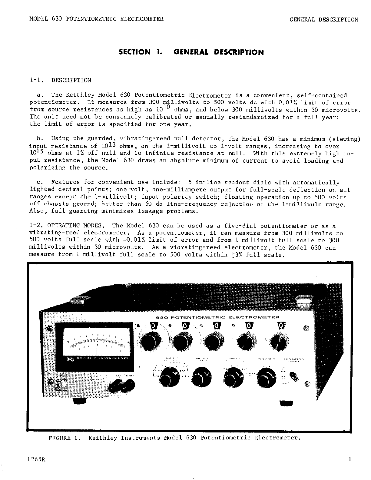
The Keithley Model 630 Potentiometric Electrometer is a convenient, self-contained
potentiometer, It measures from 300 millivolts to 500 volts dc with 0.01% limit of error
from source resistances as high as lOlo ohms,
and below 300 millivolts within 30 microvolts.
The upit need not be constantly calibrated or manually restandardized for a full year;
the limit of error is specified for one year.
in ut resistance of 1013 ohms,
F"'
Using the guarded, vibrating-reed null detector,
the Model 630 has a minimum (slewing)
on the l-millivolt to l-volt ranges, increasing to over
10 5 ohms at 1% off null and to infinite resistance at null.
With this extremely high input resistance , .the Model 630 draws an absolute minimum of current to avoid loading and
polarizing the source.
c.
Features for convenient use include:
5 in-line readout dials with automatically
lighted decimal points; one-volt,
one-milliampere output for full-scale deflection on all
ranges except the l-millivolt; input polarity switch;
floating operation up to 500 volts
off chassis ground; better than 60 db line-frequency rejection on the l-millivolt range.
Also, full guarding minimizes leakage problems.
l-2. OPERATING MODES. The Model 630 can be used as a five-dial potentiometer or as a
vibrating-reed electrometer.
As a potentiometer,
it can measure from 300 millivolts to
500 volts full scale with *O.Ol% limit of error and from 1 millivolt full scale to 300
millivolts within 30 microvolts.
As a vibrating-reed electrometer, the Model 630 can
measure from 1 millivolt full scale to 500 volts within 23% full scale.
FIGURE 1.
Keithley Instruments Model 630 Potentiometric Electrometer.
1265R
1
Page 5
GENERAL DESCRIPTION
MODEL 630 PO'TENTIOMETRIC ELECTROMETER
l-3.
APPLICATIONS.
a.
Due to its very high input resistance,
the Model 630 is very useful in making accurate dc measurements from high resistance sources frequently encountered in electrochemical
and physical-chemical research.
It is especially useful for measuring potentials from
piezo-electric crystals, electro-chemical cells, grids and plates of tubes, biological
cells and pH electrodes.
The Model 630 is also ideally suited for making Hall-effect and
fuel-cell studies,
silicon resistivity and capacitor charge measurements, and for mrasur-
ing gate potentials of field effect transistors.
b.
The null-detector output permits use with potentiometric recorders and digital volt-
meters equipped with automatic print-out.
The Model 630 is
useful
in quality control, pro-
duct development,
inspection and production.
l-4. SPECIFICATIONS.
AS A POTENTIOMETRIC ELECTROMETER:
LIMIT OF ERROR:
?O.Ol% of reading or 30 microvolts, whichever is greater, after 30-min-
ute warm-up.
Accuracy is exclusive of null-detector drift.
LONG-TERM STABILITY:
Will operate within stated limit of error for one year.
TEMPERATURE COEFFICIENT:
Does not exceed 0.001% per OC.
REPEATABILITY:
Within 0.0025% or 30 microvolts, whichever is greater.
MAXIMUM NULL SENSITIVITY:
1 millivolt full scale with 30-microvolt resolution.
INPUT RESISTANCE:
Infinite at null, from 0 to 500 volts.
10 15
ohms at.l% off null frop
0 to 500 volts with DETECTOR INPUT Switch in OPEN position.
FLOATING OPERATION:
500 volts maximum off chassis ground.
INPUT ISOLATION:
Circuit ground to chassis ground: 108 ohms shunted by 0.05 microfarad.
AS A VIBRATING REED ELECTROMETER:
VOLTAGE RANGES:
O-5 volt full scale to 500 volts in four decade ranges.
NULL RANGES:
1 millivolt full scale to 100 volts in six decade ranges.
INPUT RESISTANCE:
1013 ohms or 1010 ohms selectable by switch, L-millivolt to l-volt
ranges; 1010 ohms, 5 to 500-volt ranges.
ELECTROMETER ACCURACY:
f3% of full scale on all ranges, exclusive or noise and drift.
ZERO DRIFT:
Less than 2 millivolts per 24 hours after Z-hour warm-up.
Long term drift is
non-cumulative.
RISE TIME (10% to 90%): Less than 2.5 seconds on any range with 1010 ohm source resistance.
LINE-FREQUENCY REJECTION:
Greater than 60 db on the l-millivolt range, decreasing to 35
db on the 500-volt range.
2
1067R
Page 6
MODEL 630 POTENTIOMETRIC ELECTROMETER
GENERAL DESCRIPTION
GENERAL CHARACTERISTICS:
LINE STABILITY:
Better than 5 ppm for 10% change in line voltage.
RECORDER OUTPUT:
output:
1 volt, 1 milliampere for full-scale meter deflection on all ranges except on
l-millivolt range, where it is 10% less.
Noise:
30 microvolts peak-to-peak referred to input up to 1 cps.
Note: Recorder used must have fully isolated input, lOlo ohms minimum to ground.
POLARITY: Positive or negative, selectable by switch.
CONNECTORS: Input:
Special Triaxial. output: Banana jacks.
POWER:
105-125 or 210-250 volts (switch selected); 50, 60 or 400 cps; 50 watts.
DIMENSIONS, WEIGHT:
5-l/2 inches high x 17-l/2 inches wide x 13-l/2 inches deep; net
weight, 24 pounds.
ACCESSORIES SUPPLIED:
Model 6302 Input Cable consisting of a mating plug and 3-foot
triaxial cable.
l-5.
ACCESSORIES.
a.
Model 6301 Guarded Probe with 3-foot connecting cable allows measurements to be made
more conveniently.
Using the Probe does
not
affect any Model 630 specification.
b.
Model 4000 Rack Mounting Kit, containing two brackets and a top cover, converts the
Model 630 to fit standard 19-inch racks. Rack mounted,
the Model 630 is 5-l/4 inch&s
high x 19 inches wide x 13-l/2 inches deep. Section 6 has assembly instructions.
C. Model 6013 pH Electrode Adapter,which has a Z-foot cable and triaxial connector,
accepts Leeds & Northrop and Beckman pH electrode connectors.
The Adapter allows accurate
and convenient,pH potential measurements with the Model 630.
l-6.
EQUIPMENT SHIPPED. The Model 630 Potentiometric Electrometer is factory-calibrated
and is shipped with all components in place. All units are shipped for bench use. Model
4000 Kit may be ordered for rack mounting;
refer to Section 6 for assembly instructions.
The shipping carton also contains the Instruction Manual and the Model 6302 Mating
Connec-
tor with 3-foot triaxial cable.
016GR
3
Page 7
OPERATION
?4ODEL 630 POTENTIOMETRIC ELECTROMETER
-
Reference Voleage Dials
s303
5304
s305
S-306 It381
DETECTOR INPUT
Swirch (5102)
Receptacle
5103 5104
Switch
CO"tL-01
Switch
SwFtch
.JlOl
(S101) (R122)
(5104)
(5301)
FIGUKlc L.
I'W~~L OJU rronr: .raneL wncrols and Terminals.
The designations refer to the.
Replaceable Parts List and schematic diagram.
1265
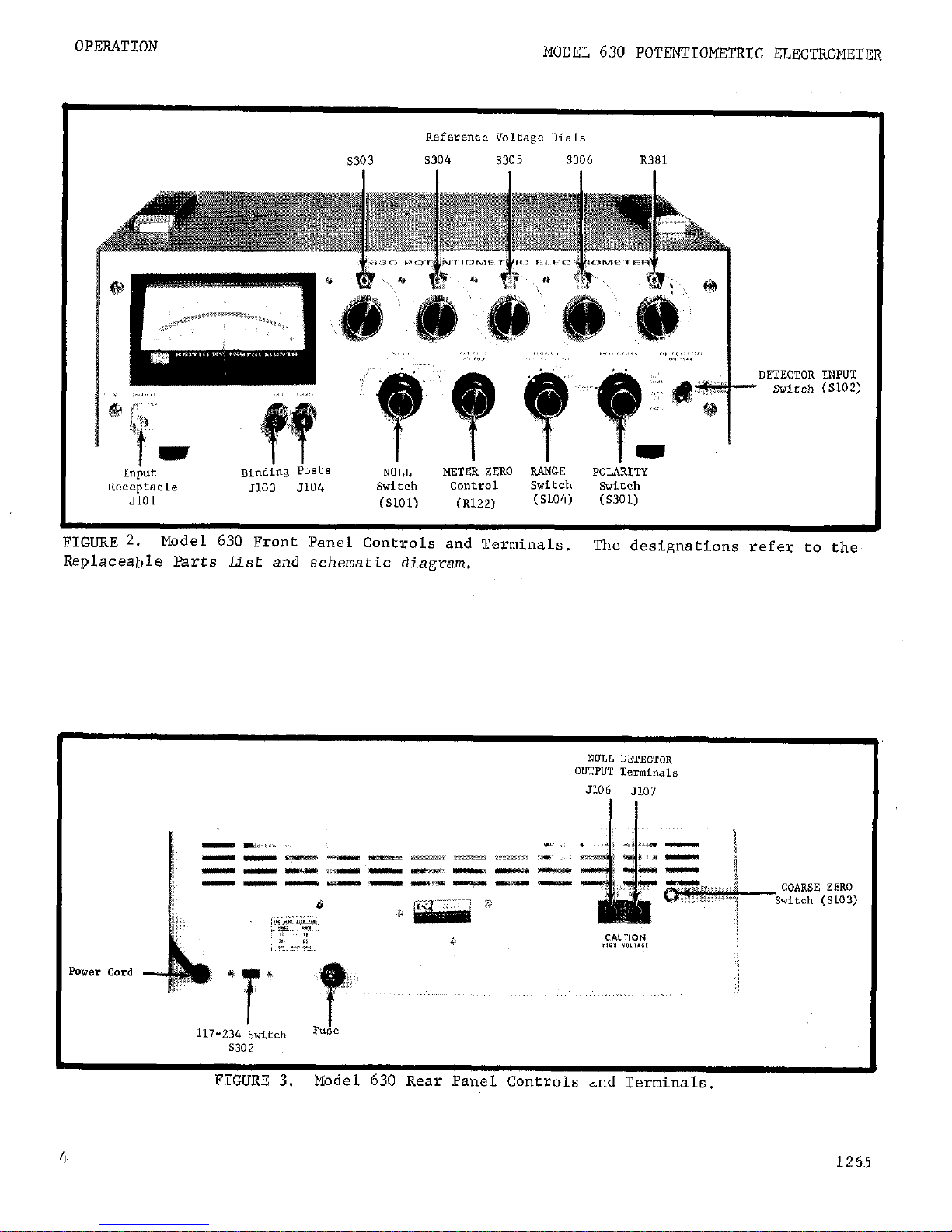
FIGURE 3. Model 630 Rear Panel
Controls
and Tarminzlr.
4
Page 8
MODEL 630 POTENTIOMETRIC ELECTROMETER
OPERATION
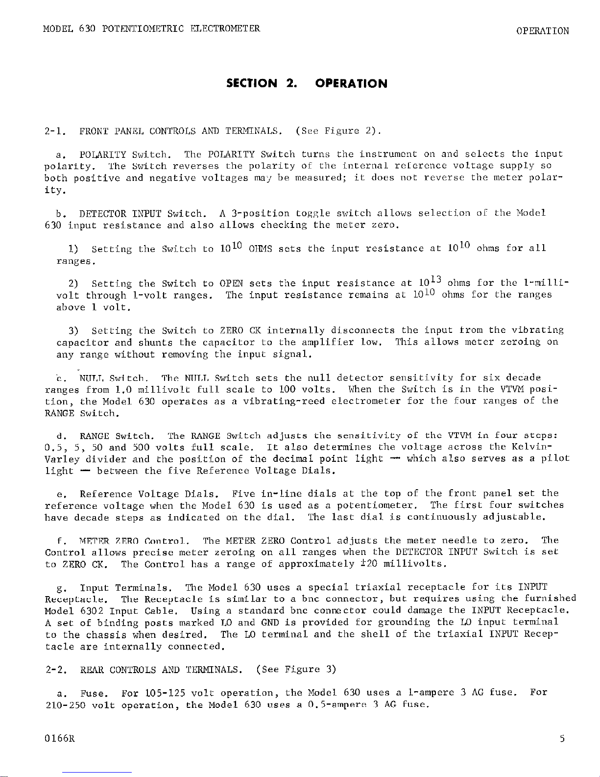
SECTION 2.
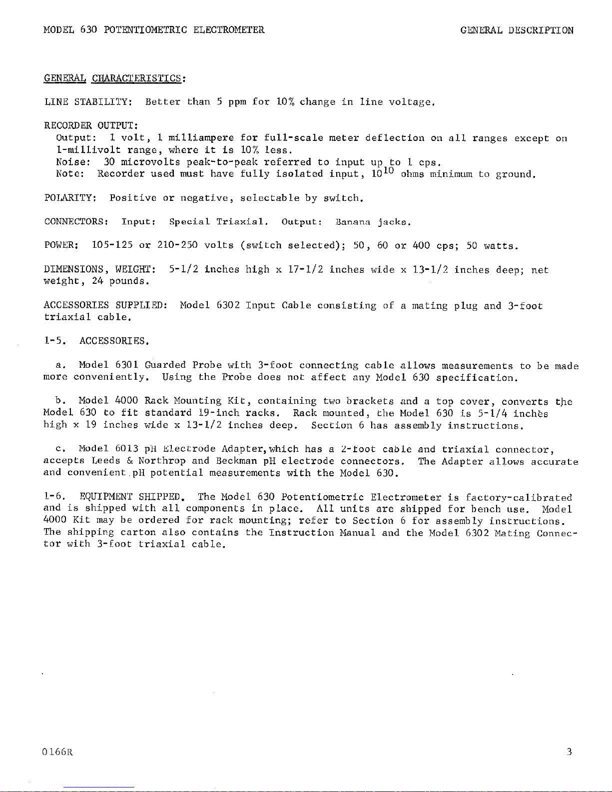
2-1. FRONT PANEL CONTROLS AND TERMINALS.
a.
polarity.
POLARITY Switch.
The Switch reverses the polarity of the internal rc,Ccrcncc voltage supply so
The POLARITY Switch turns the instrument on and sclccts
OPERATION
(See Figure 2).
the
input
both positive and negative voltages may be measured; it does not reverse the meter polar-
ity.
DETECTOR INPUT Switch.
b.
A 3-position toggle switch allows selection of
the
Model
630 input resistance and also allows checking the meter zero.
1) Setting the Switch to 10 10 OIIMS sets the input resistance at 1010 ohms for all
ranges.
Setting the Switch to OPh'N sets the input resistance at 1013 ohms for the l-milli-
2)
volt through l-volt ranges.
The input resistance remains
at
1010 ohms for the ranges
above 1 volt.
3) Setting the Switch to ZERO CK internally disconnects the input from the vibrating
capacitor and shunts the capacitor to the amplifier low. This allows meter zeroing on
any range without removing the input signal.
'c . NULL Switch.
ranges from 1.0 millivolt full scale to 100 volts.
The NULL Switch sets the null detector sensitivity for six decade
When the Switch is in the VTVM position, the Model 630 operates as a vibrating-reed electrometer for the four ranges of the
RANGE Switch.
RANGE Switch.
d.
0.5, 5, 50 and 500 volts full scale.
Varley divider and the position of the decimal point light
The RANGE Switch adjusts the sensitivity of the VTVM in four steps:
It also determines the voltage acrws the Kelvin-
- which also serves as a pilot
light - between the five Reference Voltage Dials.
Reference Voltage Dials. Five in-line dials at the top of the front panel set the
e.
reference voltage when the Model 630 is used as a potentiometer.
have decade steps as indicated on the dial.
METER ZERO Control. The METER ZERO Control adjusts the meter needle to zero. The
f.
The last dial is continuously adjustable.
The first four switches
Control allows precise meter zeroing on all ranges when the DETECTOR INPUT Switch is set
to ZERO CK.
Input Terminals. The Model 630 uses a special triaxial receptacle for its INPUT
g.
Receptacle.
Model 6302 Input Cable.
The Control has a. range of approximately 120 millivolts.
The Receptacle is similar to a bnc connector, but requires using the furnished
Using a standard bnc conmctor could damage the INPUT Receptacle.
A set of binding posts marked LO and GND is provided for grounding the LO input terminal
to the chassis when desired.
The LO terminal and the shell of the triaxial INPUT Recep-
tacle are internally connected.
2-2.
REAR CONTROLS AND TERMlNALS.
a.
Fuse.
For LOS-125 volt operation, the Model 630 uses a l-ampere 3 AG fuse.
210-250 volt operation, the Model 630 uses a 0.5-ampere 3 AG fuse.
0166R
(See Figure 3)
For
5
Page 9
OPERATION
MODEL 630 POTmTIOMETRIC ELECTROMETER
b.
Power Cord.
The Model 630 is designed for a 105-125 volt, 60-cps line source, un-
less otherwise specified on the rear panel.
The 3-wire power cord with the NEMA approved
3-prong plug provides a ground connection for the cabinet. A 3:2 prong adapter is provided.
C.
NULL DETECTOR OUTPUT.
Two terminals, marked + and -,
supply a dc signal from the
null detector.
d.
COARSE ZERO Switch.
A screwdriver adjustment is provided for bucking out the con-
tact potential of the vibrating-reed capacitor.
The Switch has a i-100 millivolt span in
ten ZO-millivolt steps.
e.
117-234 Switch.
The screwdriver-operated slide switch sets the Model 630 for 117
or 234volt ac power lines.
2-3.
PRELIMINARY PROCEDURES.
a.
Check the 117-234 Switch and the Fuse for the proper ac line voltage. Connect the
power cord.
b.
Set the Model 630 front panel controls as follows:
DETECTOR INPUT Switch
ZERO CK
RANGE Switch
500
NULL Switch VTVM
POLARITY Switch
-I.
Reference Voltage Dials
ZWXJ
The decimal light between the third and fourth Dials will light. Allow the instrument
to'warm up 30 minutes to meet the specified accuracy on all ranges.
c.
Set the NULL Switch to 1.0 MV.
Zero the meter with the METER ZERO Control.
Normally, using the COARSE ZERO Control on the rear panel is not necessary. Return the
NULL Switch to VTVM.
Check meter zero periodically.
Null detector drift can be up to 2 millivolts
per day,
which will cause inaccuracies in continuous readings.
Setting the
DETECTOR INPUT Switch to ZERO CK disconnects the input signal source from the
instrument, avoiding polarization.
It is not necessary to disconnect the input.
2-4. OPERATING PROCEDURES,
a.
The Model 630 is used first as a voltmeter to determine the approximate value of
the unknown voltage.
It is then used in the potentiometric mode to determine the voltage
to 10.01%.
6
Vibrating capacitors are extremely sensitive to shock and vibration. when
making a measurement,place the Model 630 on a vibration free, rigid structure
or on some material which will minimize vibration.
Also,
tightly tie down
the input cable and any attached circuitry; any cable flexure will generate
electrostatic charges which the Model 630 will detect.
L265R
Page 10
MODEL 630 POTENTIOMETRIC ELECTROMETER
OPERATION
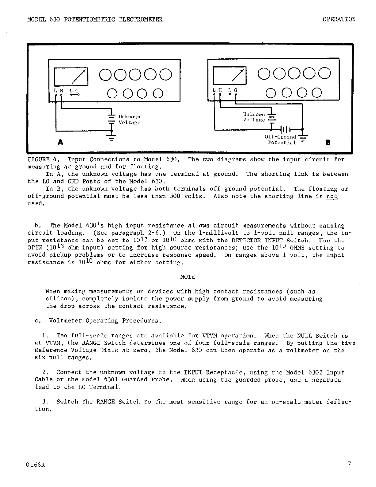
FIGURE 4.
Input Connections to Model 630. The two diagrams show the input circuit for
measuring at ground and for floating.
In A, the unknown voltage has one terminal at ground. The shorting Link is between
the LO and GND Posts of the Model 630.
In B, the unknown voltage has both terminals off ground potential. The floating or
off-ground potential must be less than 500 volts. Also note the shorting line is pe&
used.
b.
The Model 630's high input resistance allows circuit measurements without causing
circuit loading. (See paragraph 2-6.) On the l-millivolt to L-volt null ranges, the input resistance can be set to 1013 er 1010 ohms with the DETECTOR INPUT Switch. Use the
OPEN (1013 ohm input) setting for high source resistances; use the LOLO OHMS setting to
avoid pickup problems or to increase response speed.
resistance is 1010 ohms for either setting.
On ranges above 1 volt, the input
NOTE
When making measurements on devices with high contact resistances (such as
silicon), completely isolate the power supply from ground to avoid measuring
the drop acress the contact resistance.
c. Voltmeter Operating Procedures.
1.
Ten full-scale ranges are available for VTVM operation. When the NULL Switch is
at VTVM, the RANGE Switch determines one of four full-scale ranges.
By putting the five
Reference Voltage Dials at zero,
the Model 630 can then operate as a voltmeter on the
six null ranges.
2.
Connect the unknown voltage to the INPUT Receptacle, using the Model 6302 Input
Cable or the Model 6301 Guarded Probe.
When using the guarded probe, use a separate
lead to the LO Terminal.
3.
Switch the RANGE Switch to the most sensitive range for an on-scale meter deflec-
tion.
7
Page 11
OPERATION
MODEL 630 POTENTIOMETRIC ELECTROMETER
d.
Potentiometric Operating Procedures.
NOTE
Avoid large overload voltages on the null detector. No damage occurs even
with 500~volt overloads, but some open circuit offset will be caused in the
null detector.
The offset will disappear after about 5 minutes.
1.
Leave the RANGE Switch at the last setting used in the voltmeter operation. If
the voltmeter reading is negative, reverse the POLARITY Switch position.
2.
Set the first two Reference Voltage Dials to the first two digits of the unknown
voltage found in the voltmeter operation.
NOTE
When switching between the 50-volt and SOO-volt ranges and when changing the
POLARITY Switch, the meter will sometimes temporarily read off-scale.
This is
due to transients introduced when the circuit is interrupted and it does not
indicate a faulty instrument.
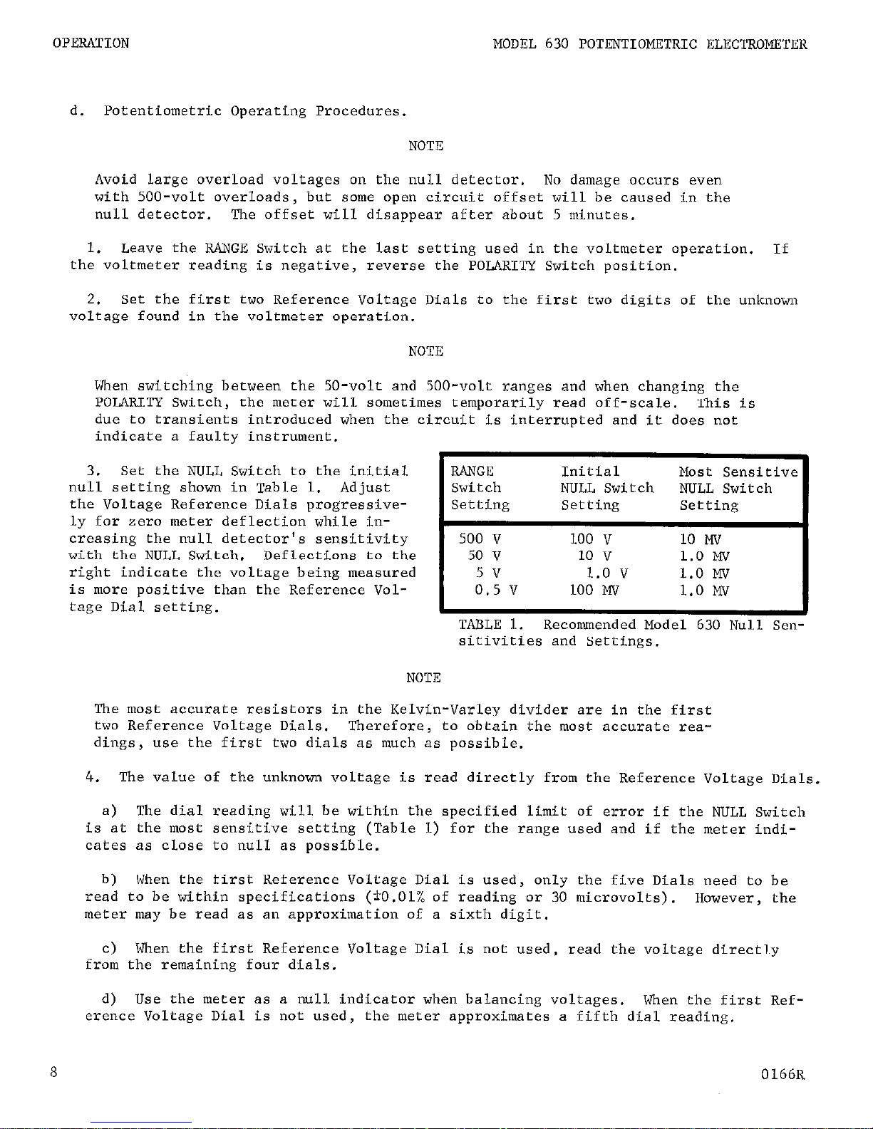
3.
Set the NULL Switch to the initial
null setting shown in Table 1. Adjust
the Voltage Reference Dials progressive-
ly for zero meter deflection while in-
creasing the null detector's sensitivity
with the NULL Switch. Deflections to the
right indicate the voltage being measured
is more positive than the Reference Vol-
I
RANGE
Initial
Most Sensitive
Switch
NULL Switch NULL Switch
Setting Setting Setting
tage Dial setting.
I
TABLE 1. Recommended Model 630 Null Sensitivities and Settings.
I
500 50 0.5 5v v v v 100 100 10 1.0 Mv v v v
1.0 1.0 10 1.0 Mv Mv Mv Mv
NOTE
The most accurate resistors in the Kelvin-Varley divider are in the first
two Reference Voltage Dials. Therefore,
to obtain the most accurate rea-
dings, use the first two dials as much as possible.
4.
The value of the unknown voltage is read directly from the Reference Voltage Dials.
a)
The dial reading will be within the specified limit of error if the NULL Switch
is at the most sensitive setting (Table 1) for the range used and if the meter indicates as close to null as possible.
b) When the first Reference Voltage Dial is used,
only the five Dials need to be
read to be within specifications (*O.Ol% of reading or 30 microvolts).
However, the
meter may be read as an approximation of a sixth digit,
c) When the first Reference Voltage Dial is not used, read the voltage directly
from the remaining four dials.
d) Use the meter as a null indicator when balancing voltages. When the first Ref-
erence Voltage Dial is not used,
the meter approximates a fifth dial reading.
8
0166R
Page 12
MODEL 630 POTENTIOMETRIC ELECTROMETER OPERATION
2-5. RECOFDER OUTPUT.
a.
Recommended recorder for use with the Model 630 is the Keithley Model 370. Any re-
corder used must be able to float 500 volts off ground and its input must be fully isolated
(1010 ohm minimum leakage resistance to ground).
The Model 370 meets these requirements.
b.
before attaching the recorder, set all Reference Voltage Dials to zero. Disconnect
the unknown voltage and short the Model 630 high input to the low. Set the NULL Switch
to 10 MV.
Connect the recorder to the OUTPUT Terminals on the Model 630 rear panel. The
370 Recorder mates directly with the Model 630 using the 3701 Cable.
c.
Set the Reference Voltage Dials to 10 millivolts to apply an accurate lo-millivolt
potential to the null detector on the lo-millivolt null range.
This will provide a full-
scale recorder output of 1 volt at 1 milliampere.
On the l-millivolt null range, the re-
corder may load the Model 630 output. On this range,
output resistance is 100 ohms.
d.
To obtain accurate results and/or
to
prevent ,damage to the instruments, the recorder
must be able to float off-ground with the Model 630. Leakage and pickup between the two
instruments should also be minimized.
The Model 370 meets these requirements.
NOTE
On the l-millivolt range there is a 10% loading error if the recorder draws
1 ma of current. Thus the output for full scale deflection will be .90 volt,
1 ma.
1. Make sure neither recorder terminal is grounded. Use a 3-wire grounded power line
for the recorder.
If a 2-wire line is used,
connect the recorder chassis and the Model
630 chassis with a separate lead.
2. Minimize all sources of leakage between the output terminals, the recorder and
ground. Use polystyrene or Teflon-insulated cable where possible. If the connecting
wires are shielded, connect the shield to the LO Post.
3. Avoid long leads between the Model 630 and the recorder.
Do not short either Model 630 output terminal to the case; this may damage the
Kelvin-Varley divider.
2-6.
EFFECTIVE INPUT RESISTANCE.
a.
The Model 630 input resistance varies. It can be set either 1013 or 1010 ohms for
the l-volt and lower ranges, and it is 1010 ohms for ranges above 1 volt.
These, however,
are not the Model 630's effective input resistances.
Its input resistance is considerably
higher due to the potentiometric principle of operation.
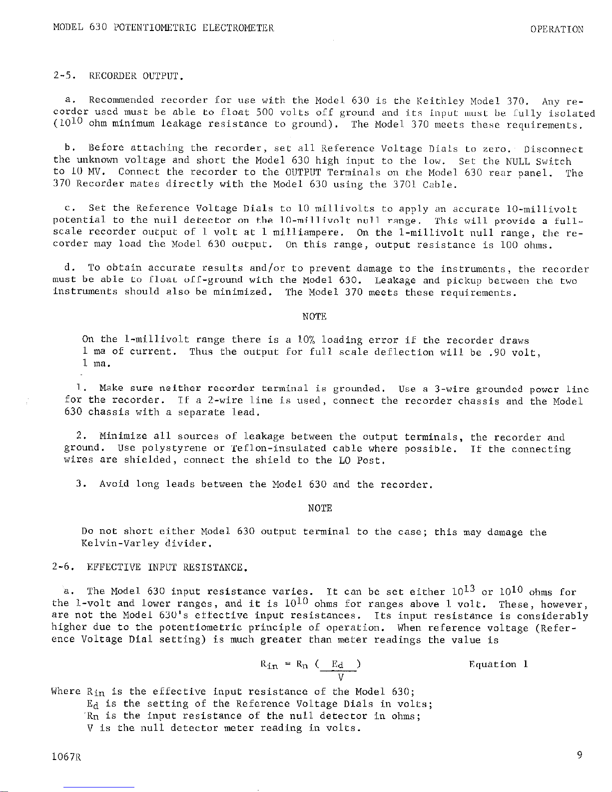
When reference voltage (Refer-
ence Voltage Dial setting) is much greater than meter readings the value is
Ri* =
Rn( Ed )
Equation 1
v
Where Rin is the effective input resistance of the Model 630;
Ed is the setting of the Reference Voltage Dials in volts;
'Rn is the input resistance of the null detector in ohms;
V is the null detector meter reading in volts.
1067R
9
Page 13
OPERATION
MODEL 630 POTENTIOMETRIC ELECTROMETER
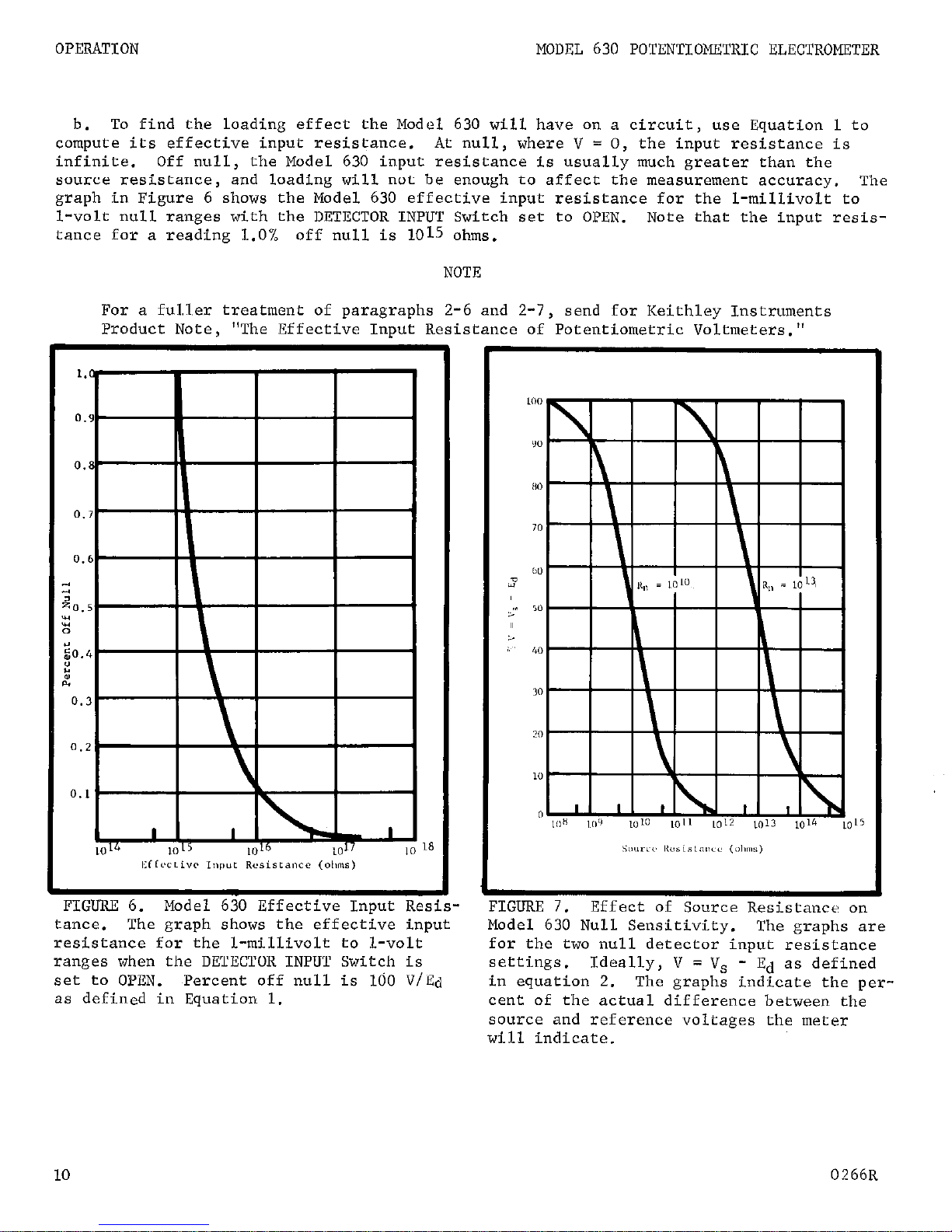
b.
To find the loading effect the Model 630 will have on a circuit, use Equation 1 to
compute its effective input resistance. At null, where V = 0, the input resistance is
infinite. Off null, the Model 630 input resistance is usually much greater than the
source resistance, and loading will not be enough to affect the measurement accuracy.
The
graph in Figure 6 shows the Model 630 effective input resistance for the l-millivolt to
l-volt null ranges with the DETECTOR INPUT Switch set to OPEN.
Note that the input resis-
tance for a reading 1.0% off null is 1015 ohms.
NOTE
For a ful.ler treatment of paragraphs 2-6 and 2-7,
send for Keithley Instruments
Product Note,
"The Effective Input Resistance of Potentiometric Voltmeters."
0.6
zo.5
0
:,o.,
”
0.3
0.2
0.L
18
FIGURE 6.
Model 630 Effective Input Res
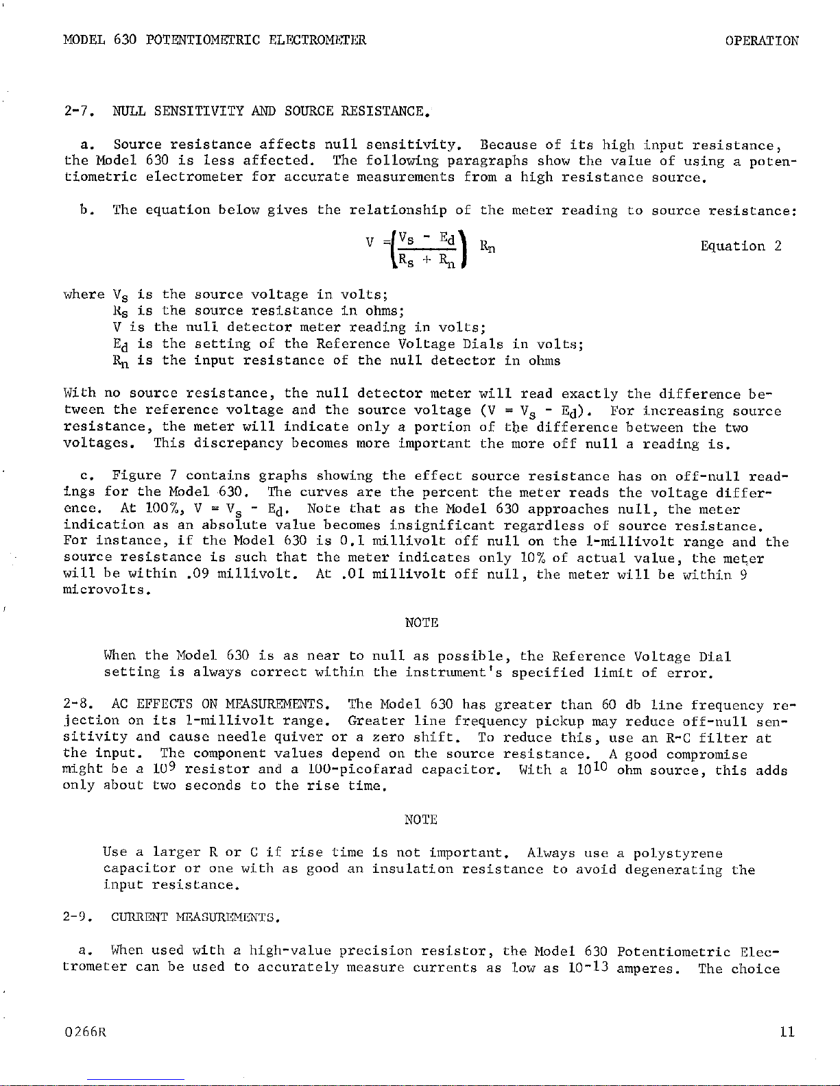
~llrluw /. F,rrecr or xxlL^ce KeSlStnnCc on
tance.
The graph shows the effective input
Model 630 Null Sensitivity.
The graphs are
resistance for the l-millivolt to l-volt
for the two null detector input resistance
ranges when the DETECTOR INPUT Switch is
settings.
Ideally, V = Vs - Ed as defined
set to OPEN. Percent off null is 160 V/Ed
in equation 2.
The graphs indicate the per-
as defined in Equation 1.
cent of the actual difference between the
source and reference voltages the meter
will indicate.
10
0266R
Page 14
MODEL 630 POTENTIOMETRIC ELECTROMETER
OPERATION
2-7.
NULL SENSITIVITY AND SOURCE RESISTANCE.
a.
Source resistance affects null sensitivity. Because of its high input resistance,
the Model 630 is less affected.
The following paragraphs show the value of using a poten-
tiometric electrometer for accurate measurements from a high resistance source.
b.
The equation below gives the relationship of the meter reading to source resistance:
Equation 2
where V, is the source voltage in volts;
R, is the source resistance in ohms;
V is the nuli detector meter reading in volts;
Ed is the setting of the Reference Voltage Dials in volts;
R,, is the input resistance of the null detector in ohms
With no source resistance, the null detector meter will read exactly the difference be-
tween the reference voltage and the source voltage (V = V, - Ed).
For increasing source
resistance, the meter will indicate only a portion of the difference between the two
voltages.
This discrepancy becomes more important the more off null a reading is.
c.
Figure 7 contains graphs showing the effect source resistance has on off-null readings for the Model ,630. The curves are the percent the meter reads the voltage difference. At loo%, V = V, - Ed.
Note that as the Model 630 approaches null, the meter
indication as an absolute value becomes insignif+cant regardless of source resistance.
For instance, if the Model 630 is 0.1 millivolt off null on the l-millivolt range and the
source resistance is such that the meter indicates only 10% of actual value, the metier
will be within -09 millivolt. At .Ol millivolt off null, the meter will be within 9
microvolts.
NOTE
When the Model 630 is as near to null as possible, the Reference Voltage Dial
setting is always correct within the instrument's specified limit of error.
2-8. AC EFFECTS ON MEASUREMENTS. The Model 630 has greater than 60 db line frequency rejection on its l-millivolt range.
Greater line frequency pickup may reduce off-null sen-
sitivity and cause needle quiver or a zero shift.
To reduce this, use an R-C filter at
the input. The component values depend on the source resistance.
might be a 109 resistor and a lOO-picofarad capacitor.
1010
A good compromise
With a
ohm source, this adds
only about two seconds to the rise time.
NOTE
Use a larger R or C if rise time is not important.
Always use a polystyrene
capacitor or one with as good an insulation resistance to avoid degenerating the
input resistance.
2-9. CURRENT MEASUREMENTS.
a. When used with a high-value precision resistor,
the Model 630 Potentiometric Elec-
trometer can be used to accurately measure currents as low as lo-13 amperes.
The choice
0266R
11
Page 15
OPERATION MODEL 630 POTENTIOMETRIC ELECTROMETER
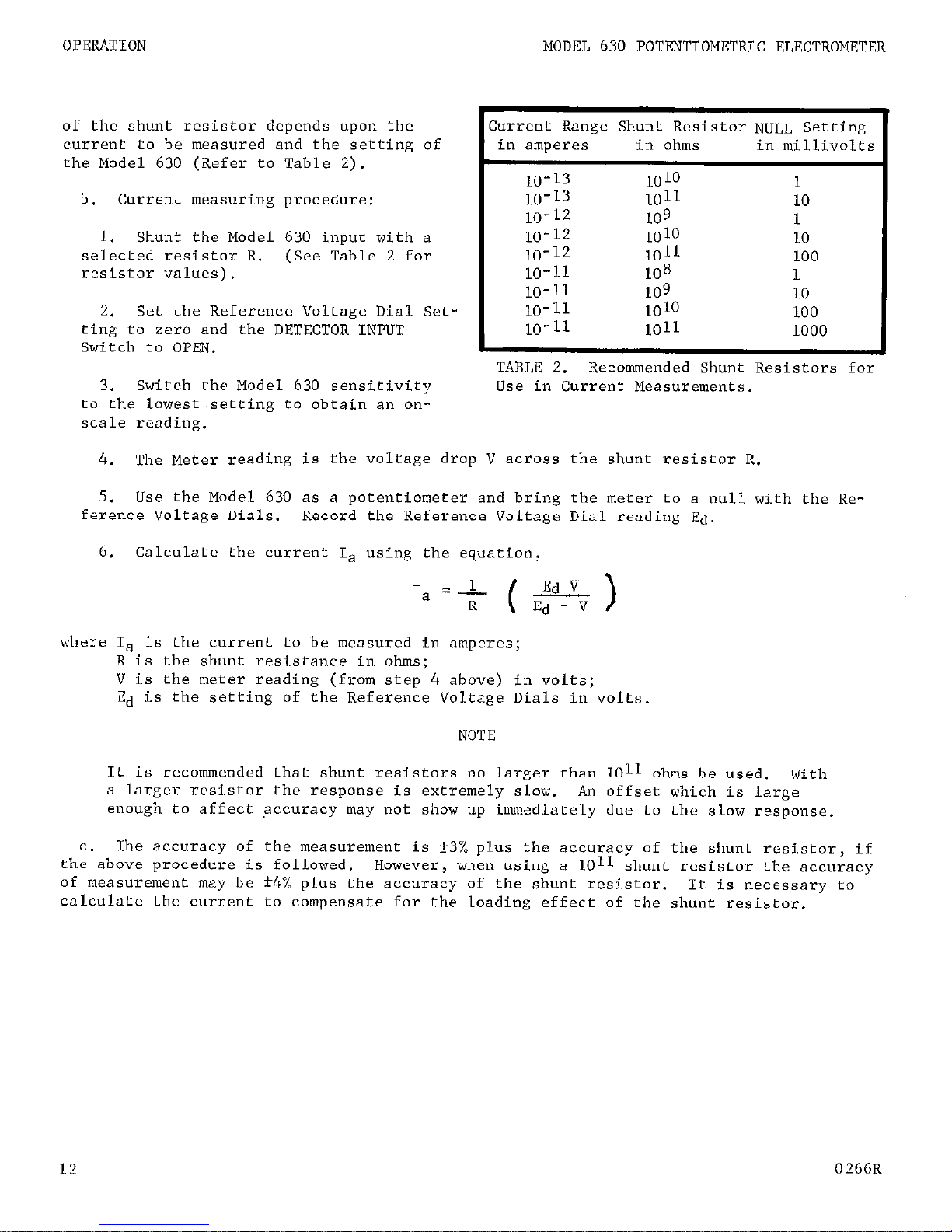
of the shunt resistor depends upon the
current to be measured and the setting of
the Model 630 (Refer to Table 2).
b.
Current measuring procedure:
Shunt the Model 630 input with a
seikcted resistor R. (See Table 2 for
resistor values).
2.
Set the Reference Voltage Dial Setting to zero and the DETECTOR INPUT
Switch to OPEN.
3.
Switch the Model 630 sensitivity
to the lowest.setting to obtain an onscale reading.
Current Range Shunt Resistor NULL Setting
in amperes in ohms
in millivolts
10-13
10 10
1
10-13
1011
10
10-12
109
1
10-12
1010
10
10-12
1011
100
10-11
108
1
I
10-11 10-11 10-11
109 1010 1011
10
100
1000
I
TABLE 2.
Recommended Shunt Resistors for
Use in Current Measurements.
4. The Meter reading is the voltage drop V across the shunt resistor R.
5.
Use the Model 630 as a potentiometer and bring the meter to a null with the Re-
ference Voltage Dials. Record the Reference Voltage Dial reading Ed.
6.
Calculate the current I, using the equation,
1
I, =-
Ed v
R
(-
Ed - V
where I,
is the current to be measured in amperes;
R is the shunt resistance in ohms;
V is the meter reading (from step 4 above) in volts:
Ed is the setting of the Reference Voltage Dials in volts.
NOTE
It is recommended that shunt resistors no larger than 1011 ohms be used
a larger resistor the response is extremely slow.
An offset which 1s largFth
.
enough
to
affect accuracy may not show up immediately due to the slow response.
c.
The accuracy of the measurement is i3% plus the accuracy of the shunt resistor, if
the above procedure is followed.
However, when using a 1011 shunt resistor the accuracy
of measurement may be *4% plus the accuracy of the shunt resistor.
It is necessary to
calculate the current to compensate for the loading effect of the shunt resistor.
12
0266R
Page 16
MODEL 630 POTENTIOMETRIC ELECTROMETER
CIRCUIT DESCRIPTION
3-1. GENERAL.
SECTION 3.
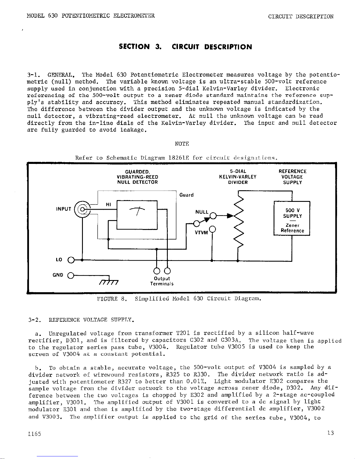
The Model 630 Potentiometric Electrometer measures voltage by the potentio-
CIRCUIT DESCRIPTION
metric (null) method. The variable known voltage is an ultra-stable 500-volt reference
supply used in conjunction with a precision 5-dial Kelvin-Varley divider.
Electronic
referencing of the 500-volt output to a zener diode standard maintains the reference sup-
ply's stability and accuracy. This method eliminates repeated manual standardization.
The difference between the divider output and the unknown voltage is indicated by the
null detector,
directly from the in-line dials of the Kelvin-Varley divider.
a vibrating-reed electrometer.
At null the unknown voltage can be read
The input and null detector
are fully guarded to avoid leakage.
NOTE
_.__ -_ __ l_..l...-__ - 1_1o ^-...
GUARDED,
VIBRATING-REED
NULL DETECTOR
INPUT
__-__- __.^ _~ _^..... -.
KELVIN-VARLEY
Guard
..,..,.. ..^. .
5.DIAL
DIVIDER
REFERENCE
VOLTAGE
SUPPLY
500 v
SUPPLY
Zener
Reference
FIGURE 8.
3-2.
REFERENCE VOLTAGE SUPPLY.
Unregulated voltage from transformer T201 is rectified by a silicon half-wave
reziifier, D301, and is filtered by capacitors C302 and C303A.
to the regulator series pass tube, V3004.
screen of V3004 at a constant potential.
To obtain a stable, accurate voltage,
b.
divider network of wirewound resistors, R325 to R330.
justed with potentiometer R327 to better than 0.01%.
sample voltage from the divider network to the voltage across zener diode, D302. Any dif-
ference between the
amplifier, V3001.
two
voltages is chopped by E302 and amplified by a 2-stage ac-coupled
'L"ne amplified output of V3001 is converted to a dc signal by light
modulator ~301 and then is amplified by the two-stage differential dc amplifier, V3002
and V3003.
The amplifier output is applied to the grid of the series tube, ~3004, to
1165
Simplified Model 630 Circuit Diagram.
The voltage then is applied
Regulator tube V3005 is used to keep the
the 500-volt output of V3004 is sampled by a
The divider network ratio is ad-
Light modulator E302 compares the
13
Page 17

CIRCUIT DESCRIPTION MODEL 630 POTENTIOMETRIC ELECTROMETER
nullify input variations.
Capacitor C305 is used in the ac feedback circuit.
c.
The temperature-compensated zener diode, D302, is used as the basic reference since
typical variations are limited to less than 20 ppm per year and 5 ppm per oC.
Thus, a
highly stable reference which eliminates manual standardization is provided with respect
to both time and temperature.
The zener diode will also withstand shock and vibration.
d.
The regulated 500-volt output of V3004 is either applied directly to the KelvinVarley divider or it is divided to 50, 5 or 0.5 volts by very stable wirewound resistor
networks. The RANGE Switch, S104, determines which network is used.
The 50-volt range
divider consists of resistors R333, R334, and R335; the 5-volt, or R333, R337 and R338;
and the 0.5-volt of R333, R339 and R340. Using potentiometers R334, R337 and R339
accurately sets the voltage division on each range.
3-3. KELVIN-VARLEY DIVIDER.
a.
The Kelvin-Varley divider precisely divides the reference voltage for nulling an
unknown voltage. It is, in effect, a constant input impedance decade potentiometer, consisting of resistors R341 through R381.
The resistors within each decade are matched;
the decades are matched for each instrument.
b.
Each decade of the Kelvin-Varley divider, except the first, R341 through R346,
parallels two resistors of the preceeding string.
Between the two contacts of the first
Reference Voltage Switch, S303, the total resistance is 40 kilohms (80 kilohms in parallel with the 80 kilohms total resistance of the four remaining strings).
With the RANGE
Switch set at 500, 100 volts dc will appear across the contacts of Reference Voltage
Switch S304, 10 volts across S305,
1 volt across 5306, and 0.1 volt across R381.
3-4.
NULL DETECTOR.
a.
The Model 630 uses a null detector which has a vibrating capacitor at the input.
The input signal is attenuated,
if necessary, and filtered. This signal is modulated by
a specially constructed capacitor,
VClOl, having one stationary plate and one moveable
plate. The signal is then amplified and applied to the meter.
b. Input resistance is greater than 1013
ohms when the DETECTOR INPUT Switch is
set
to
OPEN for the l-millivolt through l-volt ranges.
For null ranges greater than 1 volt, the
input signal is attentuated by resistors RlOl through R104.
input resistance is a constant lolo ohms.
Therefore,
above 1 volt, the
To maintain high resistance, switching with
the DETECTOR INPUT Switch (SlO2) is done using reed relays, KlOl to K103.
c. The null detector has full-scale sensitivity from 1 millivolt
to
1 volt.
Above 1
volt, resistors RlOl through R104 divide the input by a 5OO:l ratio.
The full-scale
sensitivity is determined by which of six feedback resistors, R147 through R152, is in
the circuit.
An R-C filter - R107 and capacitor Cl01 - decreases the ac input compo-
nents.
A twin-T filter, tuned for 94 cps, is connected between the plate and grid of
tube V1002.
The filter, consisting of R130, R132, R133, CllO, Cl11 and C112, provides
negative feedback for frequencies other than 94 cps.
The vibrating capacitor, VClOl, is
driven at 94 cps to further minimize ac pick-up effects.
d.
The vibrating capacitor VClOl converts the difference between the input signal and
the Kelvin-Varley divider output into an ac voltage, which is amplified by tubes VlOOl,
V1002, and half of V1003. The amplified voltage is demodulated by a bridge, diodes ~106
through D109,
and filtered by resistor R144 and capacitor Cl21.
The dc voltage is fed
14
0166R
Page 18

MODEL 630 POTENTIOMETRIC ELECTROMETER
CIRCUIT DESCRIPTION
through a cathode follower, half of tube V1003, and drives the meter.
1.
VClOl has a moveable plate driven by an electromagnet which varies the distance
between the two plates. Since the capacitance varies in inverse proportion to the distance between the plates,
a time varying capacitance is produced.
2.
If a charge is placed on the capacitor its value is
Q = CE
Equation 3
where Q is the charge;
C is the capacitance;
E is the wltage across the capacitor.
In terms of the voltage, the equation becomes E = Q/C. If Q is constant and C varies
periodically,,E must also vary. Therefore, an ac voltage which is proportional to the
magnitude of the input voltage will be produced.
e.
Resistors R147 through Rl52 form the feedback network, which divides the output
voltage for all voltmeter and null ranges except the 500-volt and l-volt ranges.
Total
output is fed back for these two ranges. The feedback voltage is returned to the low
end of the vibrating capacitor to provide stability.
f.
The Model 630 uses a "driven guard" at its input:
the feedback voltage is also
applied to the second conductor of the input cable. The potential between the input high
and low is the difference between the applied and feedback voltages.
Therefore, the cable
capacitance charges only to the difference between the two voltages. This reduces the
effect of cable capacitance,
providing faster response speed.
g.
The zero-control network consists of a 1.35-volt mercury battery, BlOl, and resis-
tors R109 through R123.
The rear panel COARSE ZERO Switch,
S103, has a span of Cl00 milli.
volts in 20-millivolt steps.
The front panel METER ZERO potentiometer, R112, has a 220
millivolt span.
h. The recorder output is developed across the top end of meter MlOl. It is one volt
for a full-scale meter deflection for all ranges above 1 millivolt. However, using a recorder with a l-milliampere movement reduces the output to 0.9 volt on the l-millivolt
range since the output impedance is 100 ohms on this range.
3-5. OSCILLATOR.
a.
The oscillator drives the vibrating capacitor and bridge demodulator and supplies
the filament voltage for ,tubes VlOOl and V1002.
b.
The output of transistor Q203,
connected as a regulator, is divided and compared
to zener diode D207. Any voltage difference is amplified by transistors Q235 and Q206,
operating as a differential voltage amplifier.
The signal is further amplified by trans-
istors 4204, Q202, and 4201 and applied to the regulator, Q2U3.
c.
A dc-to-ac converter forms the voltage to drive the vibrating capacitor, VClOl, and
the bridge demodulator, diodes D106 through D109.
Transistors Q207 and Q208 form a switch-
ing network to supply an interrupted dc voltage to transformer T202.
An extra winding
from the transformer supplies feedback to the network to sustain switching action.
Re-
sistor R213 determines the feedback magnitude.
0166R
15
Page 19

CIRCUIT DESCRIPTION
MODEL 630 POTENTIOMETRIC ELECTROMETER
3-6. GUARDING. Guarding is accomplished by floating the null detector and the input
circuitry at a voltage equal to the input voltage from a low impedance source.
This full
guarding eliminates leakage between the input terminal and ground. Such leakage in an
unguarded circuit is difficult to avoid, under laboratory conditions, and can result in
sizeable errors.
of 108
For example, in an unguarded circuit with a 1-megohm source, leakage
ohms will introduce 1% error. A guarded circuit eliminates this element of error.
16
OL66R
Page 20

MODEL 630 POTENTIOMETRIC ELECTROMETER
SERVICING
SECTION 4.
SERVICING
4-1. GENERAL. Section 4 contains the maintenance and troubleshooting procedures for the
Model 630. Follow these procedures as closely as possible to maintain the accuracy and
stability of the instrument.
4-2. SERVICING SCHEDULE.
The Model 630 needs no periodic maintenance beyond the normal
care required of high-quality electronic equipment. No part should need replacement under ordinary use except a pilot lamp, fuse or, occasionally, a vacuum tube.
4-3. PARTS REPLACEMmT.
a.
The Replaceable Parts List in Section 7 describes the electrical components in the
Model 630. Replace components only as necessary, and use only reliable replacements
which meet the specifications.
b.
Replace resistors within any one of the first three Kelvin-Varley divider decades
only as an assembly.
Refer to the Replaceable Parts List for the part number for resis-
tors R341 to R368.
Resistors R325, R326 and R328, resistors R333, R335, R338 and R340
and resistors R329 and R330 are also parts of assemblies.
Reorder using the Keithley
part number (see Section 7) and replace all resistors in the assembly.
Because of its im-
portance in maintaining power supply stability,
order zener diode D302 only from Keithley
Instruments, Inc.,
or its representative.
Refer to paragraph 4-6 for instructions
to
replace the zener.
If replacing the vibrating capacitor, VClOl, order only from Keithley
Instruments, Inc.,
or its representative.
4-4.
TROUBLESHOOTING.
63::
The following procedures are for repairing troubles which might occur in the Model
Use these procedures to troubleshoot and use only specified replacement parts.
Table 3 lists equipment recommended for troubleshooting.
If the trouble cannot be readily
located or repaired, I contact Keithley Instruments, Inc. or its representative.
Instrument Use
Keithley Model 153 dc Microvolt-Ammeter,
3% accuracy, minimum 200 megohm input
Circuit checking
resistance,
1 volt to 500 volts.
Keithley Model 610B Electrometer
Check grid bias at cathode follower
Keithley Model 50211 Ohmmeter
Check resistance
Hewlett-Packard 200CD Oscillator
Check frequency
Tektronix Type 503 Oscilloscope
Check wave forms
Grid-modulated tube tester
Test vacuum tubes
d
TABLi? 3. Equipment Recommended for Model 630 Troubleshooting. Use these instruments
or their equivalents.
0166R
17
Page 21

SERVICING
MODEL 630 POTENTIOMETRIC ELECTROMETER
I
Difficulty
Probable cause Solution
eter rattle, drift, or er-
is observed on all null
Excessive drift on most
sensitive range
Line voltage variations
cause measurements to be
out of specifications
Reference voltage supply
drifts after 30-minute
warm-up, requiring frequent
adjusting of the range controls, R327, R334, R337 and
R339
Measurements out of tolerance on all ranges
Measurements are out of
specifications on one
range other than 500-
volt range
TABLE 4.
Tube VlOOl, V1002 or V1003
Check tubes;
replace if faul
is faulty
tY
-6v power supply is drifting or oscillator circuit
is faulty
Check power supply stability
PC104, and oscillator fre-
quency (paragraph 5-7). If
I
faulty component cannot be
located, return instrument
to
factorv.
Faulty VClOl
I
Replace VClOl
Battery BlOl is faulty
I
Replace BlOl
Tube V3005 is defective
Check tube; replace if faulty
V3001, V3002, V3003 or
I
Check tubes; replace if faul,
V3004 is defective
w
One of the divider resistors, R325 to R330, is
changing value rapidly during warm-up
Return the instrument for
factory check-out
Zener diode, D302, is un-
I
Return the instrument for
stable
factory check-out
Light modulator, F,302,
is defective
Out of calibration
Check light modulator by replacing.
Refer to paragraph 5-5 for
recalibration
One of the divider resis- Return the instrument for
tars, R325 to R330, is
factory check-out
Resistor in the range divider network is faulty
Paragraph 3-2 d points out
the resistors used for each
range.
Try to bring the
ranges within specifications
by calibrating with the po-
tentiometers in the network.
See paragraph 5-5. If this
does not work, check individual resistors.
(Sheet 1).
Model 630 Troubleshooting
18
Page 22

MODEL 630 POTENTIOMETRIC ELECTROMETER
SERVICING
Difficultv
Measurements are Out of
specifications
on all ran-
ges other than 500-volt
Excessive ac interference
Non-symmetrical response
on polarity switching and
low sensitivity on most
sensitive ranges
Instrument does not respond
to a signal and offset on
all ranges
Greatly increased sensitivity on 10 and 100 null
ranges and 5, 50 and 500V
VTVM ranges
500V supply operates but
null detector is completely
inoperable
Keasurements are Out of
specifications on any range
tihen the Reference Voltage
Dials are at anv settine
other than 4 9 9 9 10 -
Probable cause
Resistor R333 is faulty
R131 out of adjustment
Oscillator frequency has
drifted
Relay K102B is defective
Relay KlOlB is defective
Fuse F201 is blown
One of the Kelvin-Varley
divider resistors is
faulty
Solution
Replace the faulty resistor
Adjust oer oaragraoh 4-8
Check frequency.
Reset to
approximately 94 cps.
(Refel
to paragraph 5-7).
Check operation of relay. 11
faulty replace with Keithley
relay or return t0 factory
Check operation of relay. If
faulty replace with new relay
from Keithlev
or return to
Check for possible short in
-6v supply (~~104).
See paragraph 5-3
TABLE 4.
(Sheet ).
Model 630 Troubleshootir :.
b.
Paragraph 6-2 describes how to remove the Model 630 :over.
Before proceeding with
the troubleshooting, check the vacuum tubes.
Normally,
replacing tubes will clear up the
difficulty.
All tubes can be readily tested on a grid-modulated tube tester.
If replac-
ing a tube does not correct the trouble, continue the procedures.
Replacing tubes does
not necessitate recalibration of the instrument.
c. Table 4 contains the mwze ccnnm~n troubles which might occur.
If the repairs indica-
ted in the Table do not clear up the trouble,
the difficulty will have to be found through
a point-by-point check of the circuits. Refer to the circuit description in Section 3
to find the more crucial components and to determine their function in the circuit. The
complete circuit schematic, 18261E, is found in Section 7,
4-5. ADJUSTING GRID BIAS OF CATHODE FOLLOWER.
The grid bias of the cathode follower,
V1003 (Figure 15), should be -3 volts. Use the Keithley Model 610B to check this value
i5"/,.
If necessary, adjust the DC BAL potentiometer, R157 (Figure 16), to this value.
0166R
19
Page 23

SERVICING MODEL 630 POTENTIOMETRIC ELECT&OMETER
4-6.
ZEhXR DIODE REPLACEMENT.
Zener diode, D302, is a reference for the voltage divider,
resistors R325 to R330.
The values of resistors R329 and R330 (Figure 20) are determined
by the reference voltage across diode D302. When the zener is replaced, the value of
these two resistors may have to be changed.
4-7. METER ADJUSTMENT.
a.
Potentiometer R155 (Figure 16) is the internal meter sensitivity adjustment. It
sets the current through the mater to indicate a full-scale deflection for a full-scale
applied voltage.
b.
Warm up the Model 630 for 30 minutes.
Set the NULL Switch to the l-volt range and
set the Reference Voltage Dials to 1.0000. Adjust potentiometer R155 until the meter
reads full scale.
4-8. ADJUSTING QUADRATURE CONTROL.
a.
Large quadrature components in the
null detector can cause poor ac rejection,
sluggish response, and, in some cases, un-
symmetrical readings on the most sensitive
ranges. Use the QUAD ADJ potentiometer,
Rl31 (Figure 16),
to buck out these compon-
ents when necessary.
While a large component is troublesome, the quadrature need
not be completely eliminated.
b.
To adjust the potentiometer, set the
Reference Voltage Dials to zero and the
DETECTOR INPUT. Switch to ZERO CK. Attach
an oscilloscope to the junction of Cl16 and
R134 (from pin 6 of V1002, Figure 15). Adjust potentiometer, R131, for the correct
wave form (Figure 9).
FIGURE 9. Wave Form with Rl31 Adjusted.
A Type 503 Oscilloscope was used; horizon-
tal sweep was 5 mseclcm; vertical, 2 v/cm.
20
0166R
Page 24

MODEL 630 POTh'NTIOMETRIC ELECTROMETER
CALIBRATION
SECTION 5. CALIBRATION
5-1. GENERAL.
a.
The following procedures are recommended for calibrating the Model 630.
Use the
equipment recommended in Table 5.
If proper facilities - especially important for cal-
ibrating an fO.Ol% instrument
- are not available or if difficulty is encountered, con-
tact Keithley Instruments, Inc.,
or its representative to arrange for factory calibration.
b.
The following procedures are covered:
Kelvin-Varley divider verification, divider
calibrate adjustment,
voltage range calibration, reference voltage supply stability test
and oscillator adjustment.
c.
If the Model 630 is not within specifications after the calibration, follow the
troubleshooting procedures or contact Keithley Instruments, Inc., or its representative.
Instrument
Electra Scientific Industries Model SV194B
Use
Range voltage calibration
Voltage Calibrator, i-0.005% accuracy with
corrections on certificate
Electra Scientific Industries Model RV722
Decade Voltage Divider; terminal linearity
21 ppm; certificate corrected to kO.2 ppm
Electra Scientific Industries Model LC875B
Lead Compensator
Hewlett-Packard Model 200CD Oscillator
Keithley Instruments Model 15OB Microvolt
hmeter
Keithley Instruments Model 241 Regulated
High Voltage Supply
Keithley Instruments Model 662 Guarded dc
Differential Voltmeter
Keithley Instruments Model 370 Recorder
Tektronix Type 503 Oscilloscope
Weston Instruments Model 3 Type 7 Saturated
Standard cell
Weston Instruments Model 66 Oil Bath
Voltage divider for range calibration
Range voltage calibration
Monitor oscillator frequency
Null detector for range calibration
Voltage supply for range calibration
Check voltages in Kelvin-Varley divider
Recorder for reference voltage supply
stability
Check wave forms
Range calibration and reference voltage
supply stability
Range calibration end reference voltage
TABLE 5.
Equipment Recommended for Model 630 Calibration.
Use these instruments or their
equivalents.
1067R
21
Page 25

CALIBRATION
MODEL 630 POTENTIOMETRIC ELECTROMETER
Control
Divider Calibrate
Quad Adjustment
Meter Calibrate
DC Balance
Oscillator
Circuit
Fig.
Refer to
Desig.
Ref. Paragraph
R104 15 5-4
R131 16 4-8
R155 16 4-7
R157 16 4-5
R210 18 5-7
500-volt Calibrate R327 20 5-5
50-volt Calibrate R334 20 5-5
5-volt Calibrate R337 20 5-5
0.5-volt Calibrate R339 20 5-5
TABLE 6.
Model 630 Internal Controls. The Table lists all internal controls, the fig-
ure picturing the location and the paragraph describing the adjustment.
5-2. CALIBRATION SCHEDULE.
a. Recalibrate the Model 630 yearly. This normally means performing the voltage range
calibration (paragraph 5-5). The other verifications need not be done.
b.
Verify the Kelvin-Varley divider (paragraph 5-3) only if trouble is suspected in it,
or if components in the divider have been replaced. Also make the voltage range calibra-
tion after verifying the divider accuracy.
c.
Check the reference voltage supply stability (paragraph 5-6) only if trouble is
suspected in the supply or if some of its components have been replaced.
5-3. KELVIN-VARLEY DIVIDER VERIFICATION.
a.
There is no in-field calibration for the Kelvin-Varley divider; its accuracy can
only be verified.
The divider accuracy depends upon matching resistors and switches. At
manufacture,
each resistor within the first two Reference Voltage switches, S303 and
S304, is matched to *0.00125%. The resistors in the switches are checked as a set to an
accuracy of better than 0.0025%.
Individual resistors cannot be replaced without remat-
ching the string at Keithley Instruments.
b. Kelvin-Varley Divider Accuracy Verification Procedures.
1.
Use the Model 662 Differential Voltmeter or equipment with better limit of
error to match the Model 630 under test.
Connect the Low end of potentiometer R38L of
the Model 630 to the HI terminal of the Model 662.
Connect both LO terminals.
NOTE
Be careful of high voltages when working within the Model 630. Up to 900 volts
dc is present at various points.
2.
Set the dials to random settings on both instruments. Settings should match to
iO.Ol%. This procedure, however, only indicates the Kelvin-Varley divider accuracy.
The errors of the two instruments may be additive, causing a false verification. The
most accurate way is to use standard procedures for checking a Kelvin-Varley divider
or to return the Model 630 to Keithley Instruments, Inc., for checking.
22
1265R
Page 26

MODEL 630 POTENTIOMETRIC ELECTROMETER
3.
If any resistor fails to test out,
the entire divider string will have to he rc-
matched at the factory.
5-4.
INPUT DIVIDER CALIBRATION.
Above 1 volt the input is divided by a constant 5OO:L
ratio. R103 is pre-selected to approximate this ratio and R104 is adjusted to trim to
this ratio more closely.
A misadjustment will show up if the Model 630 maintains spccificrl
'accuracy
on the l-volt and Lower ranges but appears in error for the higher ranges.
'To
check the divider ratio,
use the Model 241 to apply a 500-volt signal to the Hodel 630 in-
put.
The Model 630 meter should have a full scale deflection on its 500-volt range.
If
it does not,
trim R104 (Figure 15) until the meter indicates full scale.
5-5.
RANGE CALIBRATION.
a. The reference voltage supply has a 500-volt output which can be attenuated to 50, 5
or 0.5 volts.
This voltage is then divided by the Kelvin-Varley divider to provide the
accurate buckout voltage. Each of the four voltage ranges is set by internally adjusting
potentiometers R327, R334, R337 and R339 (Figure 20).
b.
The ranges are calibrated by applying an accurate voltage to the Model 630 for each
setting of the RANGE Switch.
The Model 630 is set to furnish the equivalent buckout vol-
tage, and the internal range potentiometer is adjusted until the voltmeter indicates a
null.
I
SUPPlY
I
I
d b
Mode, -~ --
i ‘C 8/,B
d I u-+-z Detector ]
o Compensator
9.9 lm
--+
_ Model
EXte"dGT
- sv 194B
(5 and 0.5"
Calibrator
OlllY)
p+Cd
I
I
Model R'J722
FIGURE 10.
Block Diagram to Establish System Accuracy for Model 630 Range Calibration.
Fully guard the entire system to prevent leakage errors.
Use a l-kilohm copper resistor
to shunt the null detector.
See Table 5 for recoanended equipment.
1067R
23
Page 27

CALIBRATION
MODEL 630 POTENTIOMETRIC ELECTROMETER
NOTE
The accuracy of the Model 630 calibration will be no greater than the
accuracy of the voltage source used for calibrating.
Unless the user is
familiar with techniques for obtaining accuracy greater than 0.002%
(20
PPm) >
it is better to return the Model 630 to the factory for range
calibration.
c.
The most critical part in range calibration is establishing a reference source
whose accuracy exceeds 0.002%..
Use the Model SV194B Voltage Calibrator for the 500, 50,
5 and 0.5-volt outputs. Establish the accuracy of these outputs by determining the corrections for the calibrator's CALIBRATION and OUTPUT dials at these outputs.
The system's
accuracy can be determined to approximately 10 ppm. Added
to
the accuracy of the standard
cell, total accuracy should be approximately 12 ppm. Note that this depends upon proper-
ly executed procedures.
d.
Procedures to Establish System Accuracy.
1.
Set up the system shown in Figure 10.
Use the 9.9-megohm extender for only the
0.5 and 5-volt output.
2.
Establish the corrections for the CALIBRATION dial setting for Model SV194B out-
puts of 500, 50, 5 and 0.5 volts.
Set the Model 241 Voltage Supply to 500 volts.
set
the Model RV722 Divider to a voltage equal to that of the standard cell.
Adjust the
Model SVl94B ratio dial until the null detector indicates a null.
The difference between the settings of the Model RV722 Divider and the ratio dial is the Model SVl94B
correction factor at 500 volts.
With this correction, the 500 volts may be set to
within approximately 12 ppm.
3.
Connect the null detector to the 50, 5 and 0.5-volt taps of the Model SVl94B Cal-
ibrator in that order.
Set the Model RV722 Divider to corresponding voltages.
Use the
9.9-megohm extender for the 5 and 0.5-volt outputs. (See Figure 10). The difference
read on the null detector is the correction factor for each of the three voltages.
These voltages may also be set to within 12 ppm.
4.
Use the four correction factors for calibrating the Model 630 range setting.
f. Procedures for Range Calibration.
1.
Set up the system shown in Figure 11.
The standard cell should be certified to
10 ppm.
Use the dial correction factors found for each output.
If the system accuracy
was properly determined,
the input voltage to the Model 630 should be correct to 20 ppm.
2.
500-volt Range Calibration: Set the Model 630 controls as follows:
DETECTOR INPUT Switch 1010 OHMS
RANGE Switch
500
Reference Voltage Dials 4 9 9.9 9 10
NULL Switch VTVM
POLARITY Switch
+
Adjust the Voltage Calibrator to apply 500 volts to the Model 630.
Turn the Model 630
NULL Switch to 10 MV and adjust the 500 V CAL potentiometer, R327 (Figure ZO), for
null on the Potentiometric Electrometer.
24
0166R
Page 28

MODEL 630 POTENTIOMETRIC FLECTROMETER
CALIBRATION
FIGURE 11. Block Diagram for Model 630 Range Calibration. Fully guard the entire system
to
prevent leakage errors. See Table 5 for recommended equipment.
3.
50-volt Range Calibration: Set the Model 630 controls as follows:
DETECTOR INPUT Switch 1010 OHMS
RANGE Switch 50
Reference Voltage Dials 4'9.9 9 9 10
NULL Switch 10 Mv
POLARITY Switch +
Adjust the Voltage Calibrator to apply 50 volts dc to the Model 630. Adjust the 50 V
CAL potentiometer, R334 (Figure ZO),
for an off-null reading on the Model 630 equal to
the correction factor at 50 volts.
4.
5-volt Range Calibration:
set the Model 630 controls as follows:
DETECTOR INPUT Switch
1010 OHMS
RANGE Switch
'5
Reference Voltage
Dials 4.9 9
9 9 10
NULL Switch 1Mv
POLARITY Switch +
Adjust the Voltage Calibrator to apply 5 volts dc to the Model 630. Adjust the 5 V CAL
potentiometer, R337 (Figure 2o), for an off-null reading on the Model 630 equal to the
correction factor at 5 volts.
5.
0.5~volt Range Calibration:
Set the Model 630 controls as follows:
DETECTOR INPUT Switch 1010 OHMS
RANGE Switch
0.5
Reference Voltage
Dials .4 9
9 9 9 10
NULL Switch
0.1 MV
POLARITY Switch
+
1067~
25
Page 29

CALIBRATION
MODEL 630 PO'TENTIOMETRLC ELECTROMETER
Oil Bath;
I
I
t
- I
-
- I
- I
,-------
FIGURE 12. Circuit Diagram for Model 630 Reference Voltage Supply Stability Test.
voltage across the 530-ohm resistor is slightly higher than the standard cell.
Model 150B
H
Null
Recorder
The
Use the
lo-kilohm potentiometer to shunt the divider voltage down. All resistors are wirewound.
See Table 5 for recommended equipment.
Adjust the Voltage Calibrator to apply 0.5 volt dc to the Model 630. Adjust the 0.5 v
CAL potentiometer, R339 (Figure ZO), for an off-null reading on the Model 630 equal to
the correction factor at 0.5 volt.
5-6.
REFERENCE VOLTAGE SUPPLY STABILITY TEST.
The reference voltage supply,
a.
consisting of the power transformer and the main supply (printed circuit PC92), is factory calibrated for an output of 500 volts dc greater
than 0.002%. The 500-volt output is adjustable to meet specifications. If the stability
of the supply is not within specifications,
then troubleshoot for a faulty component.
Routine calibration of the Model 630 does not require a stability test of the ref-
b.
erence voltage supply. However, a stability test is recommended if one of the components
in the supply is replaced.
For the 24-hour test, the 500-volt output of the reference voltage supply is divided
c.
and compared to a 1.02-volt saturated standard cell using a sensitive null detector.
Var-
iations between the reference voltage supply and the standard cell are detected by the
Model 150A and are recorded on a recorder.
Refer to Figure 12 for the block diagram of
the test circuit.
In using the test circuit,
d.
Saturated standard cells,
1.
ture coefficient and require a controlled environment during use.
ton Oil Bath, which is maintained at ~350 M.OloC, is used for the test.
the following points are important.
though extremely stable with time, have a high tempera-
Therefore, the Wes-
Unsaturated
standard cells have a lower temperature coefficient, but they do not have the long term
stability required for this test.
The resistor divider network is constructed from wire of the same spool for an
2.
extremely close temperature coefficient match (4 ppm, typically).
26
Additional stability
1067R
Page 30

MODEL 630 POTENTIOMETRIC ELECTROMETER
CALIBRATION
results when the resistors are immersed in an oil bath to hold the ambient temperature
variations
to
+O.Ol%.
e.
Procedures for the Reference Voltage Supply Stability Test.
1.
After the saturated standard cell and the resistor divider network are placed in
the oil bath, allow sufficient time for the cell to stabilize at ~35°C. (Consult Keith-
ley Instruments, Inc., or its representative for details.) Connect the standard cell
to the circuit after turning on the 500-volt supply. Set the Model 630 controls as
follows:
DETECTOR INPUT Switch
1010 OHMS
RANGE Switch 500
Reference Voltage Dials 4 9 9.9 9 10
NULL Switch 10 Mv
POLARITY Switch
OFF
Connect the resistor divider network across the Model 630's reference voltage supply,
the positive side of the divider input to the wiper arm of the last Reference Voltage
Switch, S306, and the negative side of the divider to the LO terminal on the Model 630
front panel.
2.
Connect the Model 150B and the recorder as shown in Figure 12. Set the Model 1500
to the 3-volt range.
Advance the Model 630 POLARITY Switch to -I- to put 500 volts across
the divider. If the Model 150B reads two volts, the standard cell and the divider voltages are improperly connected in series. If the circuit is correct, the Model l50B
will read zero. Increase the Model 15OB's sensitivity to the O.l-millivolt range. If
it reads more than 20 microvolts, adjust the 500 V CAL potentiometer, R327 (Figure 20),
shunting the divider.
NOTE
Any adjustment of potentiometer R327 requires all other ranges to be calibrated,
3.
After l-hour warm-up,
the drift of the entire system should not exceed i-25 micro-
volts in 24 hours.
5-7. OSCILLATOR ADJUSTMENT.
a.
The oscillator circuit drives the light modulator, vibrating capacitor and bridge.
demodulator. Before adjusting the oscillator, make sure the reference voltage supply
is operating correctly.
b.
Connect the Type 503 Oscilloscope Vertical Input to the plate and low side of tube
V1003 (Figure 15) and the Horizontal Input to the Model 200CD Oscillator. Adjust the
oscillator frequency to approximately 94 cps with potentiometer R210 (Figure 18). The
Model 630 oscillator is then adjusted for minimum meter noise - normally within a cycle
of 94 cps.
Disconnect the Oscilloscope before adjusting potentiometer R210. The
Oscilloscope will cause a small loading error.
1067R
27
Page 31

CALIBRATION
MODEL 630 POTENTIOMETRIC ELECTROMETER
R30 1
0302
Q203
Cl22
(hid,
PC-103
Null Detector Input
(Refer to Figures 15 and 16)
(Refsr to Figure 17)
FIGURE 13. Top view of Model 630 Chassis.
Front panel faces to the right.
28
0166
Page 32

MODEL 630 POTENTIOMETRIC ELECTROMETER
CALIBRATION
'IGURE 14. Bottom view of Model 630 Chassis.
Front panel faces to the right.
Figure
13 shows the top view.
0166
29
Page 33

CALIBRATION
MODEL 630 POTENTIOMETRIC ELECTROMETER
Cl01
I
A
OS101
Cl06
Cl07 Cl13
Cl15
Clll.-elj
Cl10 ----+
Cl19 -".q
Cl09
c12oa-+
c117nn"y
Dlb9
I
D108
VCiOl Djoy166
;
-cl08
+D104
~V1002
*cl16
Fl [GURE 15.
Capacitor,
Tube and Diode Locations on Printed Circuit PC-103.
Re-
fer to Figure 16 for Resistor Locations. Hidden from view, in locations A and B
are, potentiometer Rl04, resistors R124 and R154, and capacitors Cl03 and C105.
30
0166
Page 34

MODEL 630 POTENTIOMETRIC ELECTROMETER
CALIBRATION
R107-
Rl33 -mm..&
i,j
R130,
R158
R109
R15.1 R108
29
R141
thru
R118
KeS1StOr
Diode and Tube Locati
on lx-L”J.
Keter
to Figure 13 tar Capacitor,
0166
31
Page 35

CALIBRATION
MODEL 630 POTENTIOMETRIC ELECTROMETER
I,
tector Input.
Locations
on Null De
'IGURE 18.
Component bzations on -6.3 vo
ower Supply, PClO4.
32
0166
Page 36

MODEL 630 POTENTIOMETRIC ELECTROMETER
CALIBRATION
GURE 19.
Capacitor, Diode, Modulator and Tube Locations on Printed Circuit Board PC-92.
,fer to Figure 20 for Resistor
Locations.
D301
v3003
c 5
I
I
P
008
C306
,~_,,,., I‘....
VW0 1
Page 37

CALIBRATION MODEL 630 POTENTIOMETRIC ELECTROMETER
R30 2
R312 R314
R303 R305 R315
I
I I I I I
R307
“:“kc
R33111
R30
9
R310
4
R308
R332
.iii‘::*&
R328
-
?osition
R324
,m
R313
R339
R3.33
R327
R317
R316
-
R318
R319
R325
Position
R326
Position
-R330
positiac
c
R334
FIGURE 20.
Resistor Locations on Printed Circuit Board PC-92.
Refer to Figure 19 for
Capacitor, Diode, Modulator and Tube Locations.
34
0166
Page 38

MODEL 630 POTENTIOMETRIC ELECTROMETER
ACCESSORIES
SECTION 6. ACCESSORIES
6-1. MODEL 6301 GUARDED PROBE. (Figure 21)
a.
The Model 6301 is a guarded probe and shielded lead to make measurements with the
Model 630 nvxe convenient.
It does not alter any Model 630 specification.
The lead is
furnished with 3 feet of low-noise cable,
terminated by a special triaxial type plug.
The
plug connects directly into the Model 630 Input Receptacle.
b. Using the Model 6301 Probe allows point by point measurements.
Its operation witli
the Model 630 is explained in paragraph 2-4.
6-2. RACK MOUNTING.
(See Figure 22)
The Model 630 is shipped for bench use with four feet and a tilt-bail
The Model
4&% Rack Mounting Kit converts the instrument to rack mounting to the stan&nd EIA (RET@)
19-inch width.
b.
To convert the Model 630, remove the four SC~BWS at the bottom of each side of the
instrument case. Lift off the top cwer assembly with the handles; save the four screws.
To remcwe the feet aid tilt bail from the bottom cover assembly, turn the two screws near
the back. The two pawl-type fasteners will release the cwer and allow it to drop off.
Remove the feet and the tilt bail and replace the cwer (2).
c. Attach the pair of rack angles (3) to the cabinet with the four screws (4) previou
S-
y removed.
Insert the top cwer assembly (1) in place and fasten to the chassis with t
he
m
FIGURE 21.
Keithley Instruments Model 6301 Guarded Probe with the Model 630.
Besides the
probe tip,
the Model 6301 can have banana plug, alligator clip, and bnc-type connections.
Unscrew tip to make the connection.
1265
35
Page 39

ACCESSORIES
MODEL 630 POTENTIOMETRIC ELECTROMETER
two pawl-type fasteners at the rear. Store the top cover with handles, feet and tilt-bail
for future use.
6-3.
PLACING IN RACK.
The Model 630, once converted for rack mounting, easily fits into
the rack.
It is recommended, however,
that a blower be used in the rack enclosure in
which the Model 630 is mounted. The instrument specifications state a 0.002% per "C tem-
perature coefficient. A temperature rise of 5 W (9 OF) will cause a 0.01% error.
Item
(See Fig. 22)
Description
Keithley
Part No. Quantity
1 Cover Assembly
14623B 1
2
Cover Assembly, Bottom (Supplied with
Model 630)
14590B 1
3
Angle, Rack
14624B
2
4 SCYCeW)
Slot Head, lo-32 UNC-2 x l/4
(Supplied with Model 630)
----
4
5
Front Panel (Supplied with Model 630)
__--
1
I
TABLE 7.
Parts List for Model 4000 Rack Mounting Kit.
P
4
SCREW
~@COVER ASSEMBLY
OVER ASSEMBLY
FIGURE 22. Exploded
View
for Rack Mounting with Model 4000 Kit.
Refer to
'Table 7 for parts.
1265
Page 40

MODEL 630 POTENTIOMETRIC ELECTROMETER
ACCESSORIES
FIGURE 23. Model 6013 pH Electrode Adapter Connected to pH Electrodes,
The Model 6013,
shown here with the Keithley Model 601 Electrometer,
is used similarly with the Model630.
6-5.
MODEL 370 RECORDER.
a. The Model 370 Recorder is uniquely compatible with the Model 630 as well as other
Keithley electrometers,
picoammeters and microvoltmeters.
The Recorder is a high quality
economical instrument that epitomizes the performance of the Model 630 and many other
Keithley instruments, even in the most critical applications.
The Model 370 can be used
with the Model 630 to
record
over the Model 630's entire range.
b. The Model 630 has the output necessary to drive the Recorder directly (1 volt, 1
milliampere), thus eliminating the need for a preamplifier.
The Model 370 floats f500
volts off ground, enabling the Model 630 to be used to its specified off-ground voltage.
The Recorder is specially shielded to avoid pickup of extraneous signals. The response
1067R
37
Page 41

ACCESSORIES MODEL 630 POTENTIOMXTRIC ELECTROMETER
time of the Model 370 Recorder is 0.5 second; linearity is *l% of full scale. Ten chart
speeds - from 3/4 inch per hour to 12 inches per minute - are selectable with front panel
controls. The 6-inch chart has a rectilinear presentation. The Model 370 Recorder has a
self-priming inking system. Chart paper and ink refills are easy to install.
C. The Model 370 is ‘very easy to use with the Model 630.
Just connect the Model 630’s
OUTPUT Receptacle to the Model 370 with the furnished 3701 Input Cable and adjust an
easily accessible control for full-scale recorder deflection.
38
1067R
Page 42

MODEL 630 POTENTIOMETER ELECTROMETER REPLACEABLE PARTS
SECTION 7. REPLACEABLE PARTS
7-l.
REPLACEABLE PARTS LIST. The Replaceable Parts List describes the components of the
Model 630 and its accessories.
The List gives the circuit designation, the part des-
cription, a suggested manufacturer,
the manufacturer's part number and the Keithley Part
Number.
The last column indicates the figure picturing the part. The name and address of
the manufacturers listed in the "Mfg.
Code" column are in Table 9.
7-2. HOW TO ORDER PARTS.
a.
For parts orders,
include the instrument's model and serial number, the Keithley
Part Number,
the circuit designation and a description of the part. All structual parts
and those parts coded for Keithley manufacture (80164) must be ordered through Keithley
Instruments, Inc. or its representative.
In ordering a part not listed in the Replace-
able Parts List,
completely describe the part, its function and its location.
b.
Order parts through your nearest Keithley representative or the Sales Service Depart-
ment, Keithley Instruments, Inc.
amp
Cb
CbF
CbVar
CerD
Comp
compv
DCb
EAL
EMC
ETB
ETT
f
Fig.
k
Carbon
Carbon Film
Carbon Variable
Ceramic Disc
Composition
Composition Variable
Deposited Carbon
Electrolytic, Aluminum
Electrolytic, Metal Cased
Electrolytic, tubular
Electrolytic, tantalum
farad
Figure
kilo (103)
M
m
Mfg.
Mil. No.
MY
n
P
Poly
Ref.
u.
v
Ew
WWVar
mega (106)
milli (10-3)
Manufacturer
Military Type Number
Mylar
ohm
pica (lo-12)
Polystyrene
Reference
micro (10-6)
volt
watt
Wirewound
Wirewound Variable
Table 8.
Abbreviations and Symbols.
1065
39
Page 43

REPLACiUBLE PARTS
MODEL 630 POTEX'TIOMKTRIC ELECTROMETER
m 630 VBLE PARTS LIST
(Refer to Schematic Diagram 18261E for circuit designations)
CAPACITORS
Circuit Mfg. Mfg. Keithley Fig.
Desig.
Value Rating Type Code Part No.
Part No. Ref.
Cl01
Cl02
Cl03
Cl04
Cl05
Cl06
Cl07
Cl08
Cl09
Cl10
Cl11
Cl12
22
pf
56 &f 6v
47
pf
56
uf
47
if
2 Pf
0.1 I.Lf
1500 pf
2O/fXI/lOO
.a1 IJ.f
.a05
.005
Cl13 0.1 pf
Cl14
2
IJ.f
Cl15 0.1 pf
Cl16 .Ol uf
Cl17
Cl18
Cl19
Cl20
Cl21
Cl22
100 ,lf
0.5
Ilf
100 Kf 10 v ETT 05397
4
Pf
0.25
1 Pf
IJf
pf
yf
500
”
500 v
6v
500
v
50
v
400
v
600 v
pf
300/250/250 v
400 v
400
”
400
v
400
v
50
v
400
v
600
v
10 v
400
v
250
v
400
v
25
v
Poly 71590 CPR-225 Cl38-22P
ETT 01295 5MC566BP006A4 C70-56M
Poly 71590 CPR-47J Cl38-47P
ETT 01295 5MC566BP006A4 C70-56M
Poly 71590 CPR-475
ETT 37942
MY
13050 OlOOSMlA
TC302
CerD 72982 ED-1500
EMC 37942 FP335A
Poly 12673
Poly
Poly
MY
12673
12673
13050
ETT 37942
MY
13050
22P
22P C134-.005M
22P
OlOOSMlA
TC302
OlOOSMlA
CerD 72982 ED-.01
Ett
MY
05397
13050
KlOOJlOS
SMlA
KlOOJlOS
ETB
MY
CerD 56289
14655
13050
BBR4-250
SMlA
5c13
Cl38-47P
C39-2M
C73-.lM
C22-1500P
ClOO-100-60-20
Cl35-.OlM
C134-.005M 15
C73-.lM
C39-2M 15
C73-.lM 15
C22-.OlM
C78-100M 15
C117-.5M
C78-100M 15
C27-4M
C73-.25M 15
C85-1M
15
17
15
17
15
15
15
15
15
15
15
15
15
15
15
13
c201
c202
C203
C204
C205
c301
C302
c303
c304
c305
C306
c307
1000 pf
.0068
100 pf
100 pf
0.47'pf
.05
p.f
20
pf
20
pf
.a01 pf
1 Pf
.05
uf
4
Pf
IJ.f
15
”
600
v
10 v
10 " ETT
25
v
600
v
450
v
450
v
600
v
1000 "
600
v
250
v
40
EAL
CerD 72982
ETT
56289
89B224
ED-680
05397 KlOOJlOS
05397 KlOOJlOS
CerD
MY
56289
5Cll
56289 6PS-S50
EMC 39742 FP144
EMC 56289
CerD 72982
MY
MY
ETB
13050
56289
14655
TVL2762
ED-.001
Z400VB
6Ps-~50 C62-.05M
BBR4-250
C93-1000M
C22-.0068M
C78-100M
C78-100M
C85-.47M
C62-.05M
C36-20M
C36-40-20M
C22-.OOlM
C14-1M
C27-4M
18
18
18
18
18
14
19
19
19
19
19
19
1067R
Page 44

MODEL 630 POTENTIOMETRIC ELECTROMETER
REPLACEABLE PARTS
CAPACITORS (Cont'd)
Circuit
Desig.
C308
c309
c310
c311
C312
Value
50 pf
.0047 pf
.0022 pf
.05 pf
.47 pf
Rating
6v
600 v
1000 v
600 v
600 v
TYPO
EMC
CerD
CerD
MY
MY
Mfg. Mfg.
Code Part No.
56289 TEllOO
72982 ED-.0047
56289 5GAD22
56289 6PS-S50
14655 W6P47
Keithley
Fig.
Part NO.
Ref.
C17-50M 19
C22-.0047M 19
C72-.0022M 19
C62-.05M 19
ClOl-.47M
14
Circuit
Desig.
DlOl
D102
D103
D104
D105
TYPO
Silicon
Silicon
Silicon
Silicon
Silicon
Number
1~645
lN645
lN645
lN645
LN645
Mfg.
Keithley
Fig.
Code
Part No.
Ref.
01295 RF-14 14
01295 RF-14 14
01295 RF-14 14
01295 RF-14 15
01295 RF-14 15
D106 Silicon 1~645 01295 RF-14 15
D107 Si.licon 1~645 01295 RF-14 15
D108 Silicon lN645 01295 RF-14 15
D109 Silicon lN645 01295 RF-14 15
D201 Silicon MR1031B 04713 RF-30 18
D202 Silicon MR1031B 04713 RF-30 18
D203 Silicon MRlO31B 04713 RF-30 18
D204 Silicon MR1031B 04713 RF-30 18
D205 ZellfXL- LN713 12954 DZ-14 18
D206 Silicon lN645 01295 RF-14 18
D207 ZeW2-Z DZ40731A 12954 DZ-13
18
D208 Silicon lN3256 02735 RF-22 18
D209 Silicon lN645 01295 RF-14 18
D210 Silicon lN645 01295 RF-14 18
D211 Silicon LN3256 02735 RF-22 18
D301 Silicon lN2378 08520 RF-25 19
D302 ZE9lC!r - 80164 DZ-24 13
D303 Silicon lN3256 02735 RF-22 19
D304
Silicon
lN3256 02735 RF-22
1067R
41
Page 45

REPLACEABLE PARTS
MODEL 630 POTENTIOME'l'RIC ELKTROME'TER
MISCF.LLANEOUS PARTS
Circuit
Desig.
Description
Mfg. Keithley
Fig.
Code
Part No.
Ref.
BlOl
DSLOl
Neon Lamp (Mfg. No. NE-81) 08804 PL-6
15
DS301
DS302
DS303
DS304
DS305
DS306
E301
Light Modulator 80164
1514
19
E302 Light Modulator 80164
1516
19
F201
F301 (117 v)
F301 (234 v)
JlOL
5102
5103
no4
5105
JlO6
5107
5108
5201
ML01
P301
42
1067~
Battery, 1.35 v (Mfg. No. F&f-1W) 09569
DA-15
Battery Holder (Mfg. No. 2101)
94139 BH-15
14
Neon Lamp
Neon timp
Neon Glow Lamp (Mfg. No. Ale)
Neon Glow Lamp (Mfg. No. AlC)
Neon Glow Lamp (Mfg. No. AlC)
80164 1512
80164 1516
08804
PIr31
08804
PL-31
08804
PL-31
Neon Glow Lamp (Mfg. No. Ale)
08804
PL-31
13
13
13
13
Fuse, slow blow, 2 amp (Mfg. No. 313002)
Fuse, slow blow, 1 amp (Mfg. Type MDL)
Fuse, slow blow, 0.5 amp (Mfg. No. 312.500)
Fuse Holder (Mfg. No. 342012)
75915 FU-25
71400
75915
75915
18
3
3
Receptacle,
special triaxial INPUT
Mating connector for JLOL
Binding Post, M (Mfg. No. DF31BC)
Binding Post, HI (Mfg. No. DF3LGC)
Plug, bnc, mate of 5105 (Mil. No. UG-88/U)
Receptacle, bnc, mate of J104 (Mil. No.
UG-1094/U)
Banana Jack, HI (Mfg. No. 108-745-l)
Banana Jack, LO (Mfg. No. 108-745-2)
Connector, mate of 5201 (Mfg. No.
00-5002-013-103-002)
80164
80164
58474
58474
95712
95712
74970
74970
73690
FU-10
FU-6
FH-3
cs-140
BP-8B
BP-%
cs-44
cs-15
2
2
2
BJ-3
3
BJ-4
3
cs-155
Connector, mate of 5108 (Mfg. No.
02-013-013-5200)
Shorting Link (Mfg. No. 938-L)
Meter
73690
24655
80164
CS-156
BP-6
ME-38
13
Cord set, 6 feet (Mfg. No. 4638-13) 93656
co-5
3
Page 46

MODEL 630 POTENTIOMETRIC ELECTROMETER
REPLACEABLE PARTS
MISCELLANEOUS PARTS (Cont'd)
Circuit
Desig. Description
Mfg.
Keithley
Fig.
Code
Part No. Ref.
s102
SLO3
s104
--_
s301
5302
5303
s304
---
5305
---
--S306
---
--S3O,-ir"
-
Rotary Switch less components, Readout
80164
SW-118
Rotary Switch with components, Readout
80164 17080B
Dial Assembly, O-9 Readout
80164 14828A
Rotary Switch less components, Readout
80164
SW-118
Rotary Switch with components, Readout
80164
170810
Dial Assembly, O-9 Readout
80164 14828A
Rotary Switch less components, Readout 80164
SW-118
Rotary Switch with components, Readout
80164
19160B
Dial Assembly, O-9 Readout
80164 148288
Rotary Switch less components, Readout
80164 SW-127
Dial Assembly, O-LO Readout
80164 14829A
2
2
2
T201
Power Transformer
80164
TR-67
13
T202
Inverter Transformer
80164 TR-80
18
VCLOL
Vibrating Capacitor
80164
vc-1 15
RESISTORS
Circuit
Desig. Value Rating
Mfg. Mfg.
Keithley
Fig.
Type
Code
Part No. Part No.
Ref.
Rotary Switch less components, NULL 80164
Knob Assembly, Null Switch 80164
Toggle Switch, DETECTOR INPUT 80164
Rotary Switch Less comwnents. COARSE ZERO
80164
ZERO knob Assembly, METER ZERo
80164
SW-220
15LLOA
Rotary Switch less components, RANGE 80164
SW-163
Rotary Switch with components, RANGE
80164
19376B
Knob Assembly, Range Switch
80164 14838~
Rotary Switch Less components, POLARITY 80164 SW-119
Rotary Switch with components, POLARITY
80164 19161A
Knob Assembly, Polarity Switch
80164
14838A
Slide Switch, 117-234
80164 SW-151
Rotary Switch with components, Readout
80164 18355~
Dial Assembly, O-4 Readout
80164
14827A
RlOl RlOl 1010 n 1010 n 5%, 5%, 1 1 w w CbF CbF 77764 77764 BBFW BBFW RL25-1010 RL25-1010 16 16
R102 R102 16.67 IQ 16.67 IQ l%, l%, 1 1 w w DCb DCb 91637 91637 DC-L DC-L R13-16.67M R13-16.67M 16 16
SW-162
148388
SW-197
2
2
3
2
2
3
2
2
gtNNomina.1 value, factory set,
YecOn instruments with 11-step switch.
On instruments with continuous front panel switch,
R381 is used instead.
10671~
43
Page 47

REPLACEABLE PARTS
MODEL 630 POTEN'PIOMETRIC ELECTROMETER
RESISTORS (Cont'd)
Circuit
Mfg.
Mfg.
Keithley
Fig.
Desig.
Value
Rating
TYPO
Code Part NO. Part No. Ref.
R103
R104
R105
Rl06
RI.07
Rl08
R109
RllO
Rlll
R112
R113
R114
R115
R116
Rl17
R118
R119
R120
R121
R122
Rl23
RI24
Rl25
R126
RI.27
R128
11129
R130
R131
R132
RI.33
I1134
Iu35
111.36
R~L37
1~138
R139
R140
1010 n
109 R
109 12
10 kil
10 kn
10 kn
10 kn
10 kn
10 kn
10 kn
10 kn
10 kn
10 ka
4.7 kn
100 kn
8. 2 1c;i
10 ko
8. 2 k:!
109 i?
109 0
1 MC:
15 I<;:
4.7 M?
4.7 MC
333 k:
1. I<<?
166. 7 k::
333 ki!
1 M\i
15 lc
4.7 BY
4. 7 I(:~'
470 k
4,7 I<
4.7 M
DCb
00327 NllA Rl2-2M
16
CbVar 80294 3068S-l-105 RP40-1M
15
Comp
01121
EB Rl-1M 16
DCb 00327 NllA
R125-1010 16
Comp 75042 GBT R37-109 16
camp 75042 GBT R37-109
16
DCb 00327 NllA Rl2-1OK 16
DCb 00327 NllA RlZ-1OK 16
DCb
00327
NllA Rl2-1OK
16
DCb 00327 NllA R12-10K
16
DCb 00327 NllA R12-10K
16
DCb 00327 NllA RlZ-101~
16
DCb 00327 NllA RlZ-10K 16
DCb 00327 NllA RlZ-10K
DCb 00327 NllA R12-10K
DCb 00327
NllA RlZ-10K
DCb 00327
NllA R12-4.7K
Comp
01121 EB Rl-100K
16
16
16
13
Comp
01121
EB
Rl-8.2K
17
ww var 12697 62~~ RP42-1OK
2
Comp
01121
EB
Rl-8.2K 17
Comp 75042 G:BT
R37-109
15
Comp
75042 GBT R37-10g 16
Comp
01121 EB Rl-1M
16
Comp 01121 EB Rl-15K 16
Comp 01121
EB Rl-4.7M 16
camp
01121 EB Rl-4.7M
16
DCb 00327
NllA RlZ-333K
16
CompV 71450
70
RP31-11~
16
DCb 00327
NllA R12-166.7IZ
16
DCb 00327 NllA
Rl2-333K
16
Comp 01121 EB Rl-1M 16
Camp
01121 EB Rl-151~ 16
Comp 01121 EB
Rl-4.7M
16
DCb 00327
NllA Rl2-4.7K 17
DCb 00327 NllA
RlZ-470K
17
DCb 00327
NllA R12-4711 17
DCb 00327
NllA R12-4.7M
16
0166R
Page 48

MODEL 630 POTLWTIOMETRIC ELECTROMETER
REPLAC1hBLI‘: PARTS
RESISTORS (Cont'd)
Circuit
Mfg. Mfg.
Keithley Fig.
Desig. Value Rating
TYPO
Code Part No. Part NO. Ref.
R141
100 kn lO%, l/2 w
camp 01121 EB
Rl-100K 16
R142
820 ci lO%, l/2 w Comp
01121 EB
Rl-820 16
R143
330 kn lO%, l/Z w Comp
01121
EB
Rl-330K 16
R144
4.7 MO
lO%, l/2 w Comp 01121 EB
Rl-4.7M
16
R145
15 kn
lO%, 2 w
C?imp
01121
IIB
R3-15K
16
R146
1.5 kn
lO%, l/2 w
camp 01121 EB
Rl-1.5K 16
R147 10 kn l%, l/2 w
DCb 00327 NllA
R12-101~
17
R148
10 R l%, l/2 w
DCb
00327 NllA RI?-10 17
R149 100 n l%, l/2 w
DCb
00327
NllA
R12-100 17
R150 1.11 kn
l%, l/2 w
DCb
00327 NllA R12-l.llK 17
R151 200 n
l%, l/2 w
DCb
00327 NllA
Rl2-200
17
R152
2.5 kn l%, l/2 w
DCb
00327 NllA Rl2-2.5K 17
R153 10 kn
l%, l/2 w
DCb
00327 NllA Rl2-1OK 17
R154
8.06 kQ
l%, l/S w MtF
07716
CEA
R88-8.06K
15
R155
2&l
20%, .2 w
compv
71450 70 RP31-2K 16
R156
R157
R158
10 kn
1 kil
10 hl
Comp 01121 EB Rl-10K
16
compv
71450
70
RP31-1K 16
camp
01121
EB
Rl-1OK 16
R201
R202
R203
R204
R205
1 kn
10 ko
4.7 kn
470 n
2.2 kn
camp
01121
EB
Rl-1K 18
camp 01121
EB
Rl-1OK 18
Camp
01121
EB Rl-4.7K
18
Comp
01121
EB
Rl-470
18
camp
01121 EB Rl-2.2K 18
R206
R207
R208
R209
R210
5.6 kn
56 ko,
50 kn
27 ks2
20 kn
Comp 01121 EB Rl-5.6K 18
Comp
01121
EB
Rl-56K 18
DCb 00327 NllA RlZ-50K 18
Comp
01121
EB Rl-27K 18
wwvar 71450 AW RP34-20K 18
R211
R212
R213
R214
35 kn
47 12
680 11
39 kC2
DCb
00327
NllA R12-35K
18
Comp
01121
EB Rl-47 18
camp
01121
EB
Rl-680
18
Comp 01121
EB
Rl-39K 18
R301
R302
R303
R304
R305
R306
R307
108 n
220 0
820 kQ
150 Ia
50 kn
lO%, l/2 w
20%, .2 w
lO%, l/2 w
lO%, l/2 w
lO%, l/2 w
lO%, l/2 w
lO%, l/2 w
lO%, l/2 w
lO%, l/2 w
lO%, l/2 w
l%, l/2 w
lO%, l/2 w
lO%, 5 w
l%, l/2 w
lO%, l/2 w
lO%, l/2 w
lO%, l/2 w
20%, l/2 w
lO%, l/2 w
lO%, l/2 w
lO%, l/2 w
l%, 5 w
lO%, l/2 w
lO%, l/2 w
Comp
75042
GBT R37-108
Comp 01121
EB
Rl-220
Comp
01121
EB
Rl-820K
Comp
01121
EB Rl-150K
m 91637
RS-5
R4A-50K
1 Mrl
1MQ
Comp 01121 EB Rl-1M
Comp
01121
EB Rl-1M
1067R
13
20
20
20
20
20
20
45
Page 49

REPLACEABLE PARTS MODEL 630 POTENTIOMETRIC ELECTROMETER
RESISTORS (Cont'd)
Circuit
Desig.
R308
R309
R310
R311
R312
R313
R314
R315
R316
R317
R318
R319
R320
R321
R322
R323
R324
R325
Value
3.3 kiz
lM!z
470 n
470 m
2.7,
1Im
10 M!J.
680 k~
330 kil
270 kr2
2.2 l"G
5.6 kn
9<
K
1MCl
220 ksi
125 kn
Rating
lO%, l/2 w
lO%, l/2 w
lO%, l/2 w
lO%, l/2 w
lO%, l/2 w
lO%, l/2 w
lO%, l/2 w
lO%, l/2 w
lO%, l/2 w
lO%, l/2 w
lO%, l/2 w
lO%, l/2 w
lO%, l/2 w
O.l%, 50 w
0.25%, 1 w
lO%, l/2 w
lO%, l/2 w
O.l%, 2 w
Mfg. Mfg.
TYPO
camp
Comp
camp
camp
Comp
camp
Comp
camp
Comp
Comp
Comp
Comp
Comp
ww
Code
01121
01121 EB
01121
01121
01121
01121
01121
01121
01121
01121
01121
01121
01121
91637
ww 01686
Comp 01121
Comp '01121
ww 80164
Keithley
Part NO. Part No.
EB
Rl-3.3K
Rl-1M
EB
EB
EB
EB
EB
EB
EB
EB
EB
EB
EB
RH-50
T2
EB
EB
Rl-470
Rl-470K
Rl-1M
Rl-4.7K
Rl-1M
Rl-1OM
Rl-680K
Rl-330K
Rl-270K
Rl-2.2M
Rl-5.6K
R73-';
Rl30-9~
Rl-1M
Rl-220K
(1)
Fig.
Ref.
20
20
20
20
20
20
20
20
20
20
20
20
20
20
20
20
20
20
R326
R327
R328
R329
R330
R331
R332
R333
R334
R335
R336
R337
R338
R339
R340
68 kfi
68 k.Q
250 ka
1 kn
32.33 kn
180 kn
1 kn
2.563 Ici2
1 kn
250.9 n
O.l%, 2 w
lO%, 5 w
O.l%, l/4 w
0.25%, 50 w
0.25%, 50 w
lO%, l/2 w
lO%, l/2 w
O.l%, 2 w
lO%, 5 w
O.l%, l/2 w
lO%, l/2 w
lO%, 5 w
O.l%, l/2 w
lO%, 5 w
O.l%, ll2 w
ww 80164
wwvar
71450
ww 80164
ww
ww
Comp
80164
80164
01121
Comp 01121
ww 80164
WWVar 71450
ww 80164
Comp 01121
wwvar 71450
ww
80164
wwvar 71450
ww 80164
AW
EB
EB
AW
EB
AW
(1)
RP3-200
(1)
19102A
19102A
Rl-68K
ill-68K
(3)
RP3-1K
(3)
Rl-180K
RP3-1K
(3)
KP3-1K
(3)
R341
to R346
40 kn
O.OZ%, 1 w
ww 80164
(4)
f:Nominal value, factory set.
(1) R325, R326 and R328 comprise a matched set Keithley Part No. 15436A.
(2) See paragraph 4-6.
(3) R333, R335, R338 and R340 comprise a matched set, Keithley Part No. 154328.
(4) Part of Assembly with 5303, Keithley Part No. 18355B.
14
20
20
20
20
20
20
20
20
20
20
13
46
Page 50

MODEL 630 POTENTIOMETRIC ELECTROMETER
REPLACEABLE PARTS
Circuit
Mfg.
MTg.
Kcithley
Fig.
De&g. Value Rating
TYPO
Code Part No. Part No. Ref.
R347
to R357
to R368
R369
to R379
R3809W
to R389
R381""
R390
Circuit
Desig.
8 kn
.02%, 5 w
1.6 ksl
O.l%, 1 w
320 R
O.l%, 112 w
64 n O.l%, l/2 w
750 n
lO%, 4 w
1 kn
lO%, l/2 w
Number
ww
80164
ww 80164
ww 01686
ww 01686
wwvar 12697
Comp 01121
TRANSISTORS
Mfg.
Code
7044
R67-320
13
7044
R67-64
13
58~
EB
RP49-750
Rl-1K
2
14
Keithley
Fig.
Part No.
Ref.
(5)
(6)
13
13
4201
2N1381 01295
TG-8
18
Q202
2Nll83 02735
TG-11
18
Q203
2N1535 04713
TG-7
13
Q204
2N1381 01295
TG-8
18
Q205
Al380 73445
TG-32
18
Q206
A1380 73445
TG-32
18
4207
2N1183 02735
TG-11
18
4208
2N1183 02735
TG-11
18
VACUUM TUBES
Circuit
Des&. Number
Mfg.
Keithley
Fig.
Code
Part No. Ref.
VlOOl
EF86 73445
EV-EF86
15
v1002
EF86 73445
E!V-EF86
15
v1003
6U8 81454
BV-6U8
15
v3001
7025 73445
EV-7025
19
V3002
7025 73445
EV-7025
19
v3003
7025 73445
EV-7025
19
v3004
6CM6 00011
EV-6~~6
19
v3005
OG3 73445
EV-OG3
19
""On instruments with the discontinuous front panel dial, R380 has a nominal value, factbry
set,
and Ii381 replaces the rest of the string.
(5) Part of Assembly with S304.
(6) Part of Assembly with S305.
1067R
47
Page 51

REPLACEABLE PARTS MODEL 630 POTENTIOMETRIC ELECTROMETER
MODEL 6302 REPLACEABLE PARTS LIST
Description
Keithley
Part No.
Alligator clip
Insulated Banana Plug
Test Lead Cable 48" long
AC-1
BG-5
SC-20
00011 Sylvania Electric Products, Inc.
Buffalo Operations of Sylvania
Electronic Systems
Buffalo, N. Y.
00327 Welwyn International, Inc.
Cleveland, Ohio
09569 Mallory Battery Co. of Canada Ltd,
Toronto, Ontario
Canada
12673 Wesco Division
of Atlee Corp.
Greenfield, Mass.
01121 Allen-Bradley Corp.
Milwaukee, Wis.
12954 Dickson Electronics Corp.
Scottsdale, Ariz.
01295 Texas Instruments, Inc.
Semiconductor-Components Division
Dallas, Texas
01686 RCL Electronics, Inc.
Riverside, N. J.
02735 Radio Corp. of America
Commercial Receiving Tube and
Semiconductor Division
Somerville, N. J.
13050 Potter co.
Wesson, Mass.
14655 Cornell-Dubilier Electric Corp.
Newark, N. J.
24655 General Radio Co.
West Concord, Mass.
37942 Mallory, P. R., and Co., Inc.
Indianapolis, Ind.
04713 Motorola, Inc.
Semiconductor Products Division
Phoenix, Arizona
05397 Union Carbide Corp.
Linde Division
Kemet
Dept.
Cleveland, Ohio
08520
Electronic Devices, Inc.
North Ridgeville, Ohio
08804 Lamp Metals and Components
Department G. E. Co.
Cleveland, Ohio
56289 Sprague Electric Co.
North Adams, Mass.
58474 Superior Electric Co., The
Bristol, Corm.
71400 Bussmann Mfg. Div. of
McGraw-Edison Co.
St. Louis, MO.
71450 CTS Corp.
Elkhart Ind.
71590 Centralab Division of
Globe-Union, Inc.
Milwaukee, Wis.
'TABLE 9. (Sheet 1).
Code List of Suggested Manufacturers.
(Based on Federal Supply
Code Tar Manufacturers, Cataloging Handbook H4-1.)
48
0166R
Page 52

MODEL 630 POTENTIOMETRIC ELECTROMETER
REPLACEABLE PARTS
2982 Erie Technological Products, Inc.
80164 Keithley Instruments, Inc.
Erie, Pa.
Cleveland, Ohio
3445
Amperex Electronic Co. Division of
81454 Reade Mfg. Co.
North American Philips Co., Inc.
Jersey City, N. J.
Hicksville, N. Y.
91637 Dale Electronics, Inc.
3690 Elco Resistor Company
Columbus, Nebr.
New York, N. Y.
93656 Electric Cord Co.
4970 Johnson, E. F., Co.
Caldwell, N. J.
Waseca, Minn.
94139 Keystone Electronics Co.
5042 International Resistance Co.
Newark, N. J.
Philadelphia, Pa.
95712 Dage Electric Co., Inc.
5915
Littelfuse, Inc.
Franklin, Ind.
Des Plaines, 111.
7764
Resistance Products Co.
Harrisburg, Pa.
TABLE 9 (Sheet 2). Code List of Suggested Manufacturers. (Based on Federal Supply
Code for Manufacturers, Cataloging Handbook H4-1).
0166R
49
Page 53

ii-c--
 Loading...