

Page 1
INSTRUCTION MANUAL
MODEL 620
MULTI-PURPOSE ELECTROMETER
AND ACCESSORIES
Page 2
WARRANTY
We warrant each of our products to be free
from defects in material and workmanship. Our
obligation under this warranty is to repair or
replace any instrument or part thereof, except
tubes, transistors, fuses, and batteries, which,
within a year after shipment to the original buyer, proves defective on examination.
DAMAGE IN SHIPMENT
Be sure to include the instrument model num-
ber and serial number in all communications.
If the instrument is damaged when received,
or fails to operate properly, a claim should be
filed with the carrier. Upon receipt of the claim
agent’s report, we will inform you regarding
repair or replacement.
REPAIRS
When returning an instrument for repair or
recalibration, it should be securely packed
against shipping damage and sent to the fac-
tory, freight prepaid. A brief letter describing
the difficulty should accompany the instrument.
Page 3
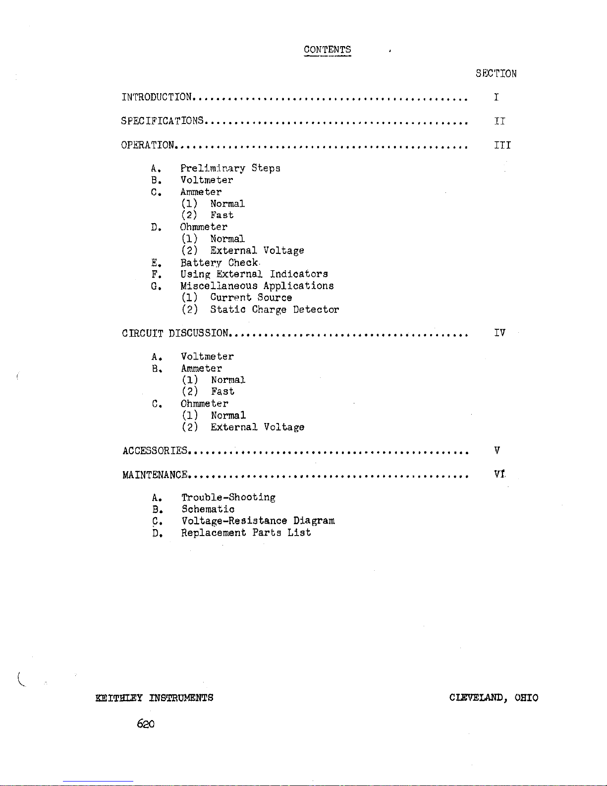
CONTENTS I
-___SIWION
INTRODUCTION
...............................................
SPECIFICATIONS
.............................................
OP&RATION
..................................................
A.
B.
C.
D.
E.
F.
0.
Prel-iminary Steps
Voltmeter
Ammeter
(1) Normal
(2) Fast
Ohmmeter
(1) Normal
(2) External Voltage
Battery Check.
Using External Indicators
Miscellaneous Applications
(1) Current Source
(2) Static Charge Detector
CIRCUIT DISCUSSION
..*..**.....,r.*....,....**.*.....*..,...
A.
Voltmeter
EL
Ammeter
(1) Normal
(2) Fast
C.
Ohmmeter
(1) Normal
(2) EXternal Voltage
ACCESSORIES
. . . . . . . . . . . ..*........*............*...*........
MAINTENANCE
. . . . . . . . . . . . . ..*...~*.....*.*....*........*...*.
A.
Trouble-Shooting
B.
Schematic
?*
Voltage-Resistance Diagram
D.
Replacement Parts List
I
IT
III
IV
V
VI.
in
KEITHLEY INSTFiUMEXTS
620
CLEVELAND, OHIO
Page 4
SECTIOI\T
I
- INTROiXJCTION
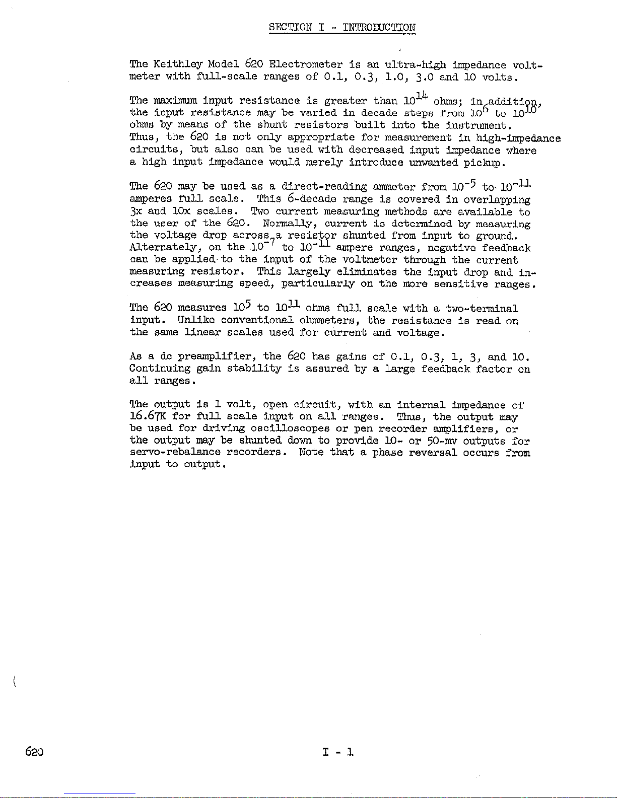
The Keithley Model 620 Electrometer
is an
ultra-high impedance volt-
meter with full-scale ranges of 0.1,
0.3, 1.0, 3.0
and
10 volts.
The maximum input resistance is greater than 1014 ohms;
in additi
the input resistance may be varied in decade steps from 106 to
n
10
YOO,
ohms by means of the shunt resistors built into the instrument.
Thus, the 620 is not only appropriate for measurement in high-impedance
circuits, but also can be used with decreased input impedance where
a high input impedance would merely introduce unwanted pickup.
The 620 may be used as a direct-reading ammeter from 10-5 to-lo-11
amperes full scale.
This (j-decade range is covered in overlapping
3x and 10x scales.
Two current measuring methods are available to
the user of the 620.
Normally, current is determined by measuring
the voltage drop across7a resist&r
shunted from input to ground.
Alternately, on the ,lO to 10 ampere ranges, negative feedback
can be applied.to the input of the voltmeter through the current
measuring resistor.
This largely eliminates the input drop and in-
creases measuring speed, particularly on the more sensitive ranges.
The 620 measures
105 to 10"
ohms full scale with a two-terminal
input.
Unlike conventional ohmmeters, the resistance is read on
the same linear scales used for current and voltage,
As a dc preamplifier, the 620 has gains of 0.1,
0.3,
1,
3,
and 10.
Continuing gain stability is assured by a large feedback factor on
all ranges.
The output is 1 volt, open circuit, with an internal impedance of
16.67K for fW.l. scale input on all ranges. Thus, the output may
be used for driving oscilloscopes or pen recorder amplifiers, or
the output may be shunted down to provide lo- or
50-1~
outputs
for
servo-rebalance recorders. Note that a phase reversal occurs from
input to output.
620
I-l
Page 5

SECTION II
- SPECIFICATIONS
Ranges:
II
b”
Voltage: 0.1
0.3,
1
3,
10-5 to 10-11
and 10 volts full
scale.
Current:
amperes full scale in lx and 3x
overlapping ranges.
(c) ohms:
105
ohms to lo"
ohms full scale on linear lx and 3x
(d)
overlapping ranges.
Meter Scales:
Left Zero 0 to 3 and 0 to 10.
Accuracy:
Voltage:
Current:
2%
of full scale on all. r3nges.
3%
of full scale
fz$m 10 amperes to 10-Y amperes.
(c) $of full scale from 3 x 10
0 t LO-l1 amperes.
4%
of full scale from 10
ohms to 109 ohms.
5s
of
full. scale from 3 x 10⁹ ohms to LOU ohms.
Resistance Standards:
109 and lOlo ohms, 2% accuracy.
oh~resistors may be expected to decrease in
value at about & per year.
Input Impedance:
On the VOLTS position, the input impedance is greater than 1014
ohms resistive,
shunted by approxiasteu
30
micromicrofarads.
Drift:
Less than 3 millivolts per hour after 2 hours warm-up.
Recorder Output:
one volt for fur. scale meter deflection,l6.6m source impedance.
Amplifier:
Frequency response is Cc to 100 cycles on all ranges. Maximum
gain is 10.
Noise is less than 2% peak to peak of fWl scale.
Front Panel Controls and Terminals:
INWJ! comector is a teflon insulated. UHF type receptacle. An
accessory binding post which plugs into the cente?Z of the connector is furnished.
A ground binding post is mounted on the
panel above the input connector.
RANGE switch is located in the center of the front panel. This
control selects VOIIp9, OHMS, or AMPERFS. On the AMPERES position,
620
II - 1
Page 6

a shunt resistor whose value is the rec%procal of the designated
range may be used to decrease the input resistance as well as to
measure current.
MULTIPLIER switch, located in the center of the front panel above
the RANGE switch, determines the voltage sensitivity of -the dc
amplifier,
and sets the voltage range when the RANGE is set on
VOLTS.
On OHMS or AMPERES, the setting of this knob multiplied. by
the OHMS or AMPIXES setting gives the full scale meter reading.
ZERC control, located at the left under the meter, is used to set
the meter to zero.
METER-BATTERY switch, at the right under the
meter, turns
the
instrument on, determines meter polarity, and tests the batteries.
ZERO CHECK-OPERATE switch, located at the bottom right, shorts the
input terminal through 5 megohms while the amplifier input is shorted.
Rear Panel Controls:
OIJTPCT receptacle for external recorders, Amphenol 8opC2F; Mat-
ing plug Amphenol 8oPC2M.
Normal-Fast control is locked in NORMAL position. In FAST positition, current measurements are made with feedback around the shunt
resistor.
COARSE ZERO is used to bring the front panel ZERO control in range
if the aaplifier is quite badly unbalanced.
Tubes:
one
5886, two 6418
Cabinet:
@" wide by &' high by
6 314"
deep. Weight
5 314
lbs.
Batteries:
Battery
!422.?
Expected Life
Bl
Mallory FMl2R or
350
hours
equivalent
(3
req'd)
E, B3, B4
tieready- #4l2 or
500 hours
equivalent
620
II - 2
Page 7

SECTION
III
- OPERATION
A.
PREPARINGTEE INSTRUMENTM)ROPERATION
(1) Set controls as follows:
MULTIPLIER: 10
RANGE SWITCH: VOLTS
ZERO C~K SWITCH:
Zero check position (horizontal).
(2) Turn the METER switch to meter +. The instrument should
come to zero in approximately 5 seconds.
(3) Rotate the MULTIPLIER switch toward the high sensitivity
end, adjusting ZERO as required. If it is impossible to zero
the meter with the front panel ZERO control use COARSE ZERO
control on rear panel to,bring the instrument within range of
the ZERO control.
(4) Connect leads as required for measurement. If high im-
pedance is involved, the input should be shielded using s. co-
axial connection or shielded enclosure.
The various 600 series
accessories may be used. See Section V.
If the impedance is low (below about lOlo ohms) and leads can
be kept short, the binding post adapter furnished with the in-
strument may be used.
B. MEASURING VOLTAGE
Place RANGE switch.at VOLTS.
Turn MULTIPLIER switch to expected
sensitivity and check meter zero.
If the sensitivity of the in-
strument is increased., recheck the zero reading.
C.
MEASURING CURRENT
(1) NOFMATJ method (lo-5 anperes to lo-l1 amperes full scale),
Turn PANGE switch to desired AMPERES range. Make sure the switch
&t the rear of the instrument is on the NORMAL position. Connect
current source to the input. Ful& scale sensitivity is the
product of the settings of the RANGE switch and. MULTIPLIER.
Check zero with the ZERO CHECK switch and then read the unknown
current. The full. scale voltage drop is the setting of the
MULTIPLIER switch.
(2) FAST method (10-T to LO"= amperes full scale).
Proceed as above except with the FAST-NORMAL stitch at FAST.
The input drop is now negligible and the input circuit time
constant is reduced at least 100 times. Observe the following
cautions:
620
III - 1
Page 8
(4 U
se only the ZERO CHECK switch to check zero. Do
not short the input.
(b) The low side of the output is no longer at ground.
Therefore, a recorder attached to the output must not be
pounded to the Model 620.
(c) i?o not use this method for the measurement of capacitor
leakage.
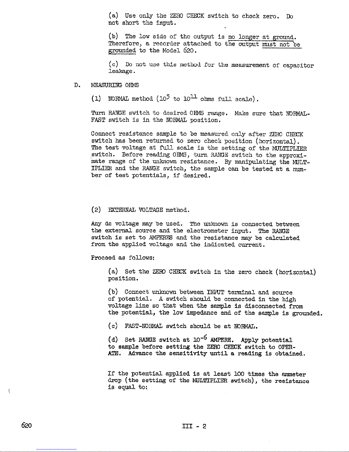
D. MEASURING OHMS
(1) NOW method (lo5 to 1Ol-l ohms full scale).
Turn RANGE switch to desired OIQ4S range. Make sure that NOBMALFAST switch is in the NORMAL position.
Connect resistance sample to be measured only after Z&W CHECK
switch has been returned to zero check position (horizontal).
The testvoltage at full scale is the setting of the MULTIPLIER
switch. Before reading OHMS, turn RANGE switch to the approxi-
mate range of the unknown resistance.
By manipulating the WLT-
IPLIER
and the RANGE switch, the sample can be tested at a num-
ber of test potentials, if desired.
(2) EXTERNAL VOLTWE method.
Any dc voltage may be used. The unknown is connected between
the external source and the electrometer input. The RANGE
switch is set to AWEE
and the resistance may be calculated
from the applied voltage and the indicated current.
Proceed as follows:
(a) Set the Z&XI CHECK switch in the zero check (horizontal)
position.
(b) Connect unknown between IEHJT terminal and source
of potential.
A switch should be connected In the high
voltwe line so that when the sample is disconnected from
the potential, the low impedance end of the sample is grounded,
(c) FAST-E0FWA.L switch should be at NORMAL.
(d) Set RANGE switch at 10e6 AMPERE. Apply potential
to sample before setting the ZlDiU CKEXK switch to OPEBATE.
Advance the sensitivity until a reading is obtained.
If the potential applied is at least 100 times the ammeter
drop (the setting of the MULTIPLIER switch), the resistance
is equal to:
620 III - 2
Page 9

FCTEJ!JTIAL APPLIED
cuRREm READING
If the potential applied is not large compared to the smmeter drop, the resistance is equal to:
WTENTIAL APPLIED -
INPUT
DROP (VOLTS),
CURREIKC Pt.&WING
(e) If the noise in the source is low enough it is possible
to have the FAST-RCFNAL on FAST and the input drop need
not be connidored in the calculation.
E.
BATI'ERY
CmK
Turn METER-BATTERY switch to Bl, B2, etc. All batteries should read
half scale or higher on the meter.
All batteries are tested directly.
Bl consists of three.l.34 volt bat-
teries in series and all three, should be replaced if the reading
in Bl position is less than half scale.
F.
USIX EXTERNAL INDICATORS
The output of the Model 620 may be used to drive servo rebalance
recorders as well RS high impedentie devices such as oscilloscopes
and dc amplifiers.
(1) For use with servo rebalance recorders:
The output circuit consisto~of a 16.G’71< resistor through which
60
microamperes flow for full scale deflection of the panel
meter.
Shorting the output does not affect the meter reading
of the Model 620; low impedances placed across the output terminals will lower the terminal voltage for full scale deflection,
Thus, if it is deslred that the output voltage for full scale
of
50
millivolts is required, 878 ohms should be used.
(21, For use with oscilloscopes and high impedance dc smpllfiers,
the output is one volt for full scale input on
any range,
with a phase inversion.
The frequency response is dc to 100 cycles on all ranges. The
maximum amplitude which can be delivered by the amplifier is
approximately 2 volts peak to peak.
CURRENT SOURCE
G.
When
measuring ohms, the instrument is designed to supply R constant
current to sny device placed across its input terminals. The magnitude
of the cbrrent is equal to the reciprocal of the designation on the
OHMS segment Of the MEGE switch.
Therefore the instroment may be
usedas a current source for calibration of other instruments if
desired.
620
Turn RANGE switch to OHMS and ZERO CHfXK switchto OPERATE. The
current that is supplied on each range is the reciprocal of the OHMS
III - 3
Page 10

setting, and is not affected by the setting of the MULTIPLIER switch.
H. STATIC CHARGE MkXSUF@NEWIS
The Instrument Is zeroed and the RANGE switch placed on VOLTS. The
MUI/l'IPLIEFl Is placed at 3 or 10 volts f7iJ.l scale. The charged object
is then brought near the uncovered, unshielded input connector of the
620. Depending on the distance between the charge and the Instrument
a voltage will be induced on the input terminal and can be read on
the panel meter.
The instrument zero should be checked frequently
since accumulation of charge due to the electrometer tube grid current will cause a slow,drift of input voltage.
Connecting a capacitor across the input reduces the drift due to
grid current and also the sensitivity to charge. An electrode connected to the INPUT terminal which increases the capacitance between
the INPUT terminal and the charged object will increase the sensitivity
to charges.
620 III - 4
Page 11

SECTION IV - CIRCUIT DISCUSSION
The basic element of the Model
voltmeter with a full scale sen
input impedance greater than 10"
620
is a highly accurate, stable dc
tivity of 100 millivolts and an
ohms shunted by 30 micro-microfarads.
The various connections necessary for current and resistance measurements will be discussed following the detailed description of the
voltmeter.
VOLTMETER
A.
Refer to DR
1.3364~
at the rear of the manual. The amplifier proper
consists of Vl and V2. V3
is a cathode follower which
drives the amplifier at
the same instantaneous po-
Vl + V2'
11 &?I
I
I.1 “NY,,
ic
L.
-22
tential as the input sig-
nal.
In other words the
neutral or low impedance
terminal of the amplifier
is not grounded but is attached to the outnut cathode
follower.
Fig.
620-1.
shows
this diagramatically.
PIQIJRE 620-1
Since the amplifier proper is driven by the cathode follower, the
plus and minus 22 volt batteries for the cathode follower are referred
to input ground while the battery supplies for the amplifier are
referred to amplifier ground which is "floating".
In subsequent
discussion, referrence will be made to the amplifier ground as "floating ground' and to cathode follower ground as "output ground".
The amplifier input consists of a
ment is operated in series with V2 and V3 from battery Bl.
5886
electrometer tube. The fila-
The control
grid of Vl, the electrometer tube, is protected by R102, a 1000 Megohm
resistor, bypassed for high frequencies by C102.
The ZEXC controls set the output to zero by adjusting the dc voltage
on the screen of the electrometer tube.
The voltmeter sensitivity is determined by the value of the feedback
resistor selected by S4, the MULTIPLIER switch. With full scale input
on any range a current of
60
microamperes will flow thru
~1.36
producing
an output of one volt.
620
IV-l
Page 12

620
PUT
5
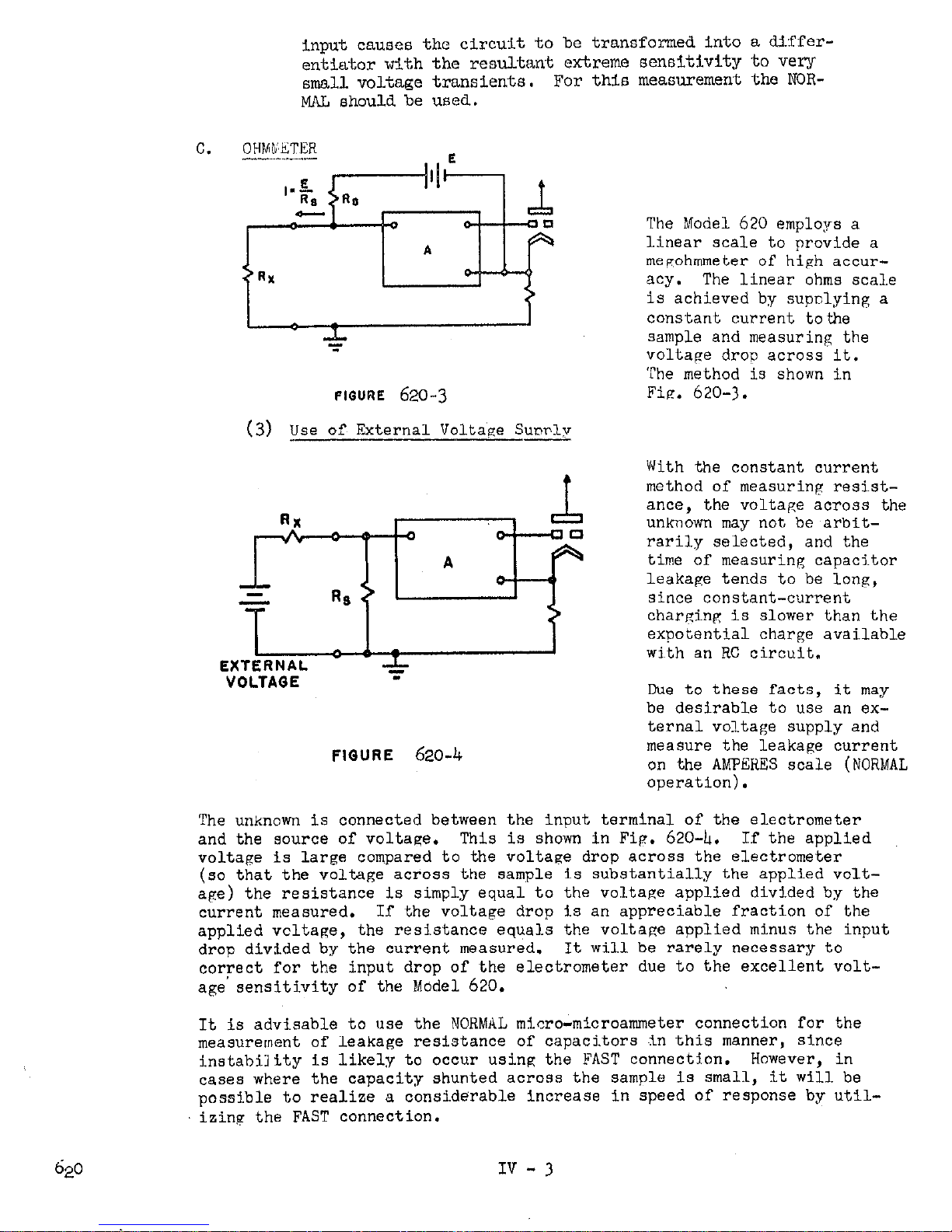
(1) Shunt Resistor Method (NIXWAL)
In the normal operating connection as shown in Fig.
620-2
CWrent is measured by placing a resistor across the input te@.nals
and measuring the voltage drop. Currents from 10-5 to loamperes may be measured by thdS~m&thod
s nce the range switch
selects resistors ranging from 10 to 10
10
ohms in decade steps.
The voltage drop is selected by the MULTIPLIER switch; the setting
is the input voltage drop for full scale meter deflection.
(2) Feedback Method (FAST)
In the voltmeter discussion above, floating ground is driven
by the cathode follower and output ground is connected to the
low impedsnce side of the input connector. In the FAST connection,
the amplifier ground is connected to the low impedance side of
the input; the output ground floats, and negative feedback is
applied to the input through the shunt resistor,
In the Model
620
it is possible to use this connection with
currents of O.lmicroamperes or less.
To change the connection,
remove the lock from NORMAL-FAST switch at the bottom of the
rear panel and change it to the FAST position. The advantages
of this connection are:
(a) The effect of input capacity is largely neutralized,
that Is, the time constant of the input and cable capacity
and. the shunt resistor used will be decreased at least
100 times as compared to the NXNAL connection, corresponding to a 100-fold Increase in response speed.
(b) The input drop will be reduced about 100 times.
It will be seen that this connection converts the 620 into an
operational amplifier with a resistor from the output to the
input.
Therefore, the following cautions apply:
(a) The input cannot be shorted since this will remove
the feedback.
(b) The internal impedance of the current source being
measured should not be less than about one-tenth of the
value of the feedback resistor used for measurement.
(c) this connection should not be used for measuring the leak-
age current of capacitors since the connection of a capacitor to the
Iv-2
Page 13
input causes the circuit to be transformed into a differentiator with the resultant extreme sensitivity to very
small voltage transients.
For this measurement the NOR-
MAL should be used.
FIGURE
620-3
(3)
Use of, External Volta’se S&y
EXTERNAL
VOLTAQE
FIQURE
620-4
The Model 620 employs a
linear scale to provide a
me~ohmmeter of hish accur-
acy.
The linear ohms scale
is achieved by
supnlying a
constant current to the
sample and measuring the
voltage drop across it.
The method is shown in
Fie. 620-j.
With the constant current
method of measuring resistance, the voltage across the
unknown may not be arbitrarily selected, and the
time of measuring capacitor
leakage tends to be long,
since constant-current
charging is slower than the
expotential charge available
width an RC circuit.
Due to these facts, it may
be desirable to use an ex-
ternal voltage supply and
measure the leakage current
on
the AMPERES scale (NORMAL
operation).
The unknown is connected between the input terminal of the electrometer
and the source of voltage,
This is shown in Fig. 620-h. If the applied
voltage is large compared to the voltage drop across the electrometer
(so that the voltage across the sample is substantially the applied voltape) the resistance is simply equal to the voltage applied divided by the
current measured.
If the voltage drop is an appreciable fraction of the
applied vcltage, the resistance equals the voltage applied minus the input
drop divided by the current measured.
It will be rarely necessary to
correct for the input drop of the electrometer due to the excellent voltage’ sensitivity of the Model 620.
It is advisable to use the NORMAL micro-microammeter connection for the
measurement of leakage resistance of capacitors fin this manner, since
instability is likely to occur using the FAST connection. However, in
cases where the capacity shunted across the sample is small, it will be
possible to realize a considerable increase in speed of response by utilizing the FAST connection.
IV -
3
Page 14

Some precautions are recommended when testina capacitors.
Re sure that
capacitors have discharged be,fnre removino from test circuit.
With the
ZLRO CHECK swjtch jn the zero check nnsit.inn thr input, i~.s shorted to pround
throuph
L.7
megohms providing a dischuve pa~th for the capacitor.
It should be further noted that capacitor measuremc:nt 1,s likely to be
a slow process in any case due to the fact that jut may take con?iderahle
time for the molecular orientation of the dielectric to take place at,
the testinp potential.
It may take minutes or even hours in sow cases
to achieve a stable readl.w.
620
TV - II
Page 15

SETION v
- ACCESSORIES
MODEL
6101~
ACCESSORY PROBB:
The Model 610111 probe coneists of an Input connector, 3 feet of low
noise cable and a shielded probe head. Its purpose is to allow con-
venient connection to the electrometer input.
MODEL
6102~
- 1O:lDIVIDER PROBE:
The Model 610~ divider probe is intended for general purpose measurements where axi extension of the upper voltage range of the
620
is desired.
resistance is 1016 ohm.
The divis on ratio Is 1O:l correct to 1% and the probe input
The probe is supplied with a mating con-
nector and 3 feet of cable.
WDRL
6103~
- 1OCC:l DIVIDER PROBE:
The Model 6103~ probe is intended for very high voltage measurements
at high impedance. The division ratio is 1ooO:l correct to 346 and
the probe input resistance is lO= ohme.
The probe 18 supplied with
& mating connector and 3 feet of cable.
The
Model
6104 Test Adapter is intended for use in making measurementa
wherein complete shield& of the component under test ie required.
External. terminals are provided for either grounded tests, or a test
requiring an external voltage source.
V-l
Page 16

SECTION VI - MAINTENANCE
No periodic maintenance is required other tban checking the batterlea
as provided for by the front panel control.
The method of performing
these checks is outlined in Section III - E.
The calibration of the voltmeter is set by Rllg located on the vertical
printed circuit board.
This is set at the factory and should not re-
quire adjustment.
If recalibration is performed, an accurate voltage
source should be used.
A.
TIXXJBU SHOOTING
The circuit is completely described in Section IV. Study of that
section will facilitate any trouble shooting.
The most usual trouble encountered is that on the most sensitive
voltage range, with the input shorted, it is not possible to bring
the meter pointer to zero. However, before assuming that the instrument is at fault make sure that resetting the COARSE ZFXI control
at the rear of the Instrument will not bring the instrument back
into balance. If this does not work it will be necessary to remove
the instrument cover to gain access to all circuitry. The instru-
ment cover is removed by unscrewing the three screws on each side
of the instrument and. lifting the cover. With the cover removed,
follow this procedure:
(1) Short floating ground to output ground, removing the negative feedback. This is most conveniently done by shorting
the two ends of the FAST-NORMAL switch on the rear panel. The
instrument will. become very sensitivie and it will be difficult
to keep the meter on scale with the zero control.
(2) Measure the plate voltage of Vl as indicated on the voltage
resistance diagram.
If it is possible to swing the plate volt-
age thru the correct value with the zero control the first stage
is working properly.
(3)
Check V2 and then
V3
in~,the~ same manner. When a stage
Is found that will not give the correct voltage check the tube
itself and then the associated components.
(4)
Since the tube filaments are in series all stages will be
inoperative if any one filament is open. With the instrument
on measure the individual filament voltages. The defective tube
will have the full
3.6
volts across Its filament terminals.
620
VI-1
Page 17

RI.41
Resistor,~, Depos@ed carbon, 9 K, I$, 15 watt
s-2
Switch,~ check zero
s-3
Switch, Coarse !&ro
RL2-3CUC
sww-310
SW-x%
s-4,
Stitch, Multiplier
Page 18

REPLACEABLE PARTS LIST - MODEL
620
circuit
De&@;.
Description
Part No.
Rl20
RI.21
Rl22
RI.23
RI.24
RJ-25
RI.26
RE7
RI.28
RX9
R130
R131
~132
R133
R134
R135
R136
RUT
~1.38
RI39
R140
S-l
,.
S-2
s-3
s-4
s-5
NOTE:
Resistor, Composition 1OM 10s
.5
watt
RI.-1OM
Resistor, composition 22M 10% .5 watt
Rl-22M
Resistor, deposited carbon 15K l$ .5 watt
Rl2-15K
Resistor, deposited carbon 3.3M 1% .5 watt
RX?-3.3M
Resistor, Deposited Carbon 68OK 1% .5 watt
Rl2-68CK
Resistor, Deposited Carbon 390K 1% .5 watt
Rl2-390K
Resistor, Composition l2M lO$ .5 .watt
Rl-l2M
Resistor, composition 22M 10% ,5 watt
RI.-22M
Resistor, composition 4.7K 10% .5 watt Rl-4.7K
Potentiometer 20K
RPl.2-20K
Resistor, Deposited Carbon 220K l$ .5 watt RX?-220K
Resistor, Deposited Carbon
1.667X
1% .5 watt RX?-1.667((u)
Resistor, Deposited Carbon 5K l$
-5
watt Rl2-5K
Resistor, Deposited Carbon
16.667
1% .5 watt RX.?-16.6'7K
Resistor, Deposited Carbon 5OK~l$ .5 watt
RI&50K
Resistor, Deposited Carbon 166.7K 1% .5 watt Rl2-166.v
Resistor, Deposited Carbon 16.667 1% -5 watt Rl2-16.67K
Resistor, Composition 150K
5% .5
watt
Rig-150K
Resistor, Composition '75OK 5s .5 watt Rig-750K
SEW
as
~138
Same as ~138
Switch, Range,
SW-103
Stitch, Coarse Balance'
~~-10.06
Switch, Multiplier
SW-104
Switch, Fast -- Normal
SW-45
Switch, Meter -- Battery
SW-105
(*) indicates nomlna1 value subject to variation in inavid-
ual instruments.
Page 19

RFPL~E~~LE PARTS LIST - MODEL
620
Circuit
De&g.
Description
Pati No.
V-l
Tube,
V~CUUII 5886
sd&ed
Ev-5886-5
v-2
Tube, Vacuum
6418
~~-6418
v-3
Sane as V-2
Page 20

L
-
L
 Loading...