

Page 1
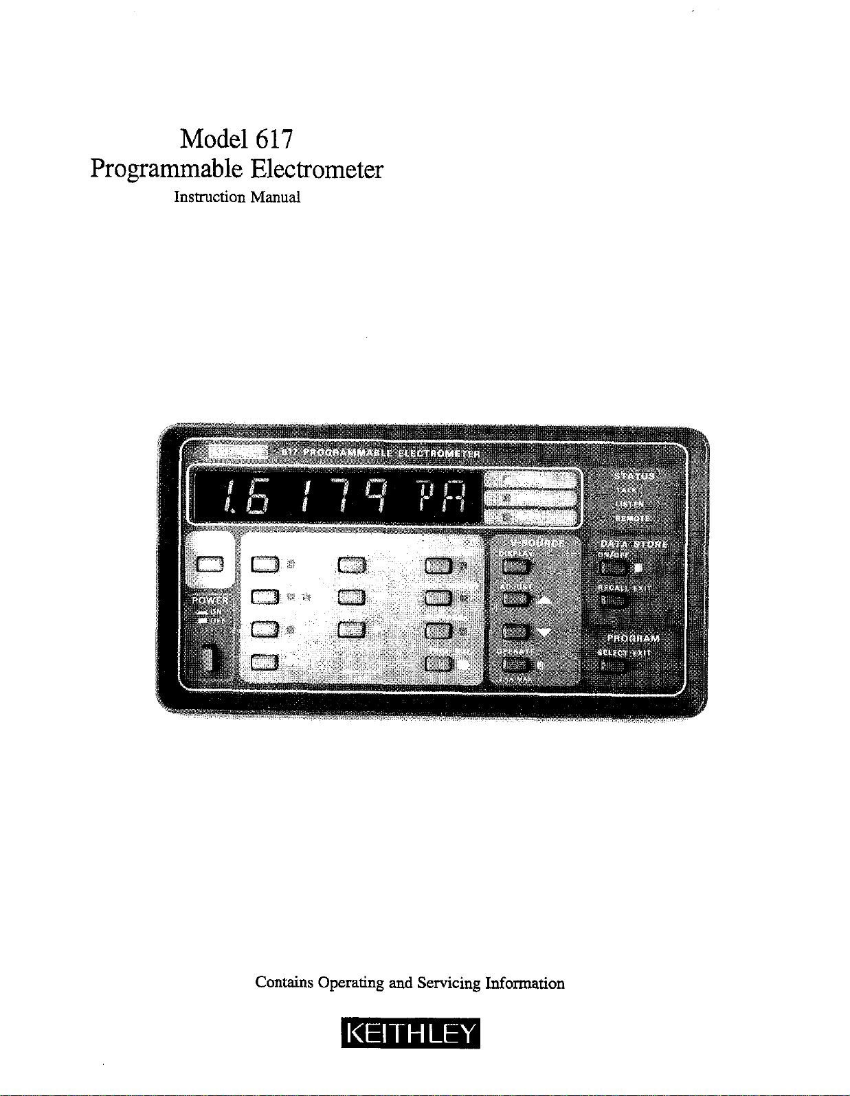
Model 617
Programmable Electrometer
Instruction Manual
Contains Operating and Servicing Information
Page 2

WARRANTY
Keithley Instruments, Inc. warrants this product to be free from defects in material and workmanship for a period of 1 year from date of
shipment.
Keithley Instruments, Inc. warrants the following items for 90 days from the date of shipment: probes, cables, rechargeable batteries,
diskettes, and documentation.
During the warranty period, we will, at our option, either repair or replace any product that proves to be defective
To exercise this warranty, write or call your local Keithley representative, or contact Keithley headquarters in Cleveland, Ohio. You will
be given prompt assistance and return instructions. Send the product, transportation prepaid, to the indicated service facility. Repairs
will be made and the product returned, transportation prepaid. Repaired or replaced products are warranted for the balance of the original warranty period, or at least 90 days.
LIMITATION OF WARRANTY
This warranty does not apply to defects resulting from product modification without Keithley’s express written consent, or misuse of
any product or part. This warranty also does not apply to fuses, software, non-rechargeable batteries, damage from battery leakage, or
problems arising from normal wear or failure to follow instructions.
THIS WARRANTY IS IN LIEU OF ALL OTHER WARRANTIES, EXPRESSED OR IMPLIED, INCLUDING ANY IMPLIED
WARRANTY OF MERCHANTABILITY OR FITNESS FOR A PARTICULAR USE. THE REMEDIES PROVIDED HEREIN ARE
BUYER’S SOLE AND EXCLUSIVE REMEDIES.
NEITHIZR KEITHLEY INSTRUMBNTS, INC. NOR ANY OF ITS EMPLOYEES SHALL BE LIABLE FOR ANY DIRECT, INDIRECT, SPECIAL, INCIDENTAL OR CONSEQUENTIAL DAMAGES ARISING OUT OF THE USE OF ITS INSTRUMENTS AND
SOmWARE EVEN IF KEITHLEY INSTRUMENTS, INC., HAS BEEN ADVISED IN ADVANCE OF THE POSSIBILITY OF
SUCH DAMAGES. SUCH EXCLUDED DAMAGES SHALL INCLUDE, BUT ARE NOT LIMITED TO: COSTS OF REMOVAL
AND INSTALLATION, LOSSES SUSTAINED AS THE RESULT OF INJURY TO ANY PERSON, OR DAMAGE TO PROPERTY.
Keithley Instruments, Inc. - 28775 Aurora Road - Cleveland, OH 44139 - 216-248-0400 - Fax: 216-24X-6168 - http://www.keithley.com
Page 3

Model 617 Programmable Electrometer
Instruction Manual
0 1984, Keithley Instruments, Inc.
Test Instrumentation Group
All rights reserved.
Cleveland, Ohio, U.S.A.
Document Number: 617-901-01 Rev. C
Page 4
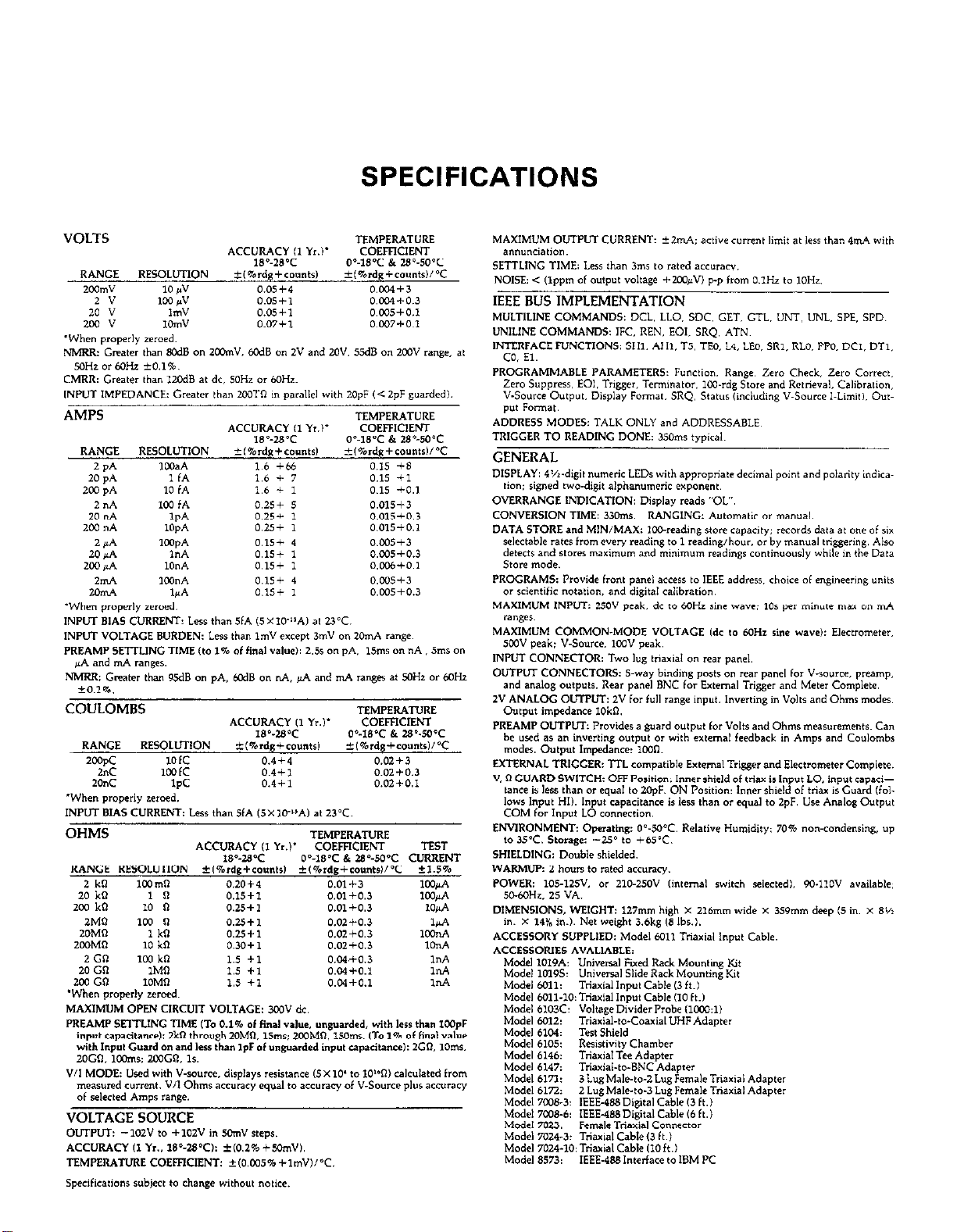
SPECIFICATIONS
Page 5
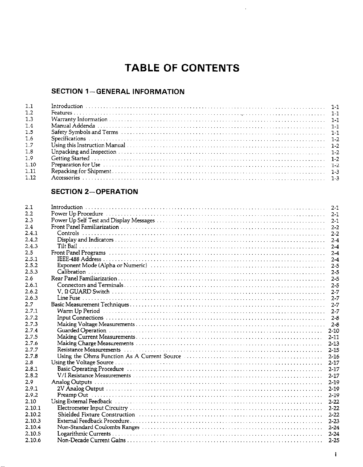
TABLE OF CONTENTS
SECTION l-GENERAL INFORMATION
1.1
1.2
1.3
1.4
1.5
1.6
1.7
1.8
1.9
1.10
1.11
1.12
2.1
2.2
2.3
2.4
2.4.1
2.4.2
2.4.3
2.5
2.5.1
2.5.2
2.5.3
2.6
2.6.1
2.6.2
2.6.3
2.7
2.7.1
2.7.2
2.7.3
2.7.4
2.7.5
2.7.6
2.7.7
2.7.8
2.8
2.8.1
2.8.2
2.9
2.9.1
2.9.2
2.10
2.10.1
2.10.2
2.10.3
2.10.4
2.10.5
2.10.6
Introduction
Features ...................
Warranty Information
ManualAddenda..
Safety Symbols and Terms
Specifications
Using this Instruction Manual
Unpacking and Inspection
Getting Started
Preparation for Use
Repacking for Shipment.
Accessories
...................
..
...........
.............
.......
..................
.....
........
.................
.............
.........
....................
SECTION 2-OPERATION
Introduction
Power Up Procedure
Power Up Self Test and Display Messages
Front Panel Familiarization
Controls
Display and Indicators
TiltBan
Front Panel Programs
IEEE-488 Address
Exponent Mode (Alpha or Numeric)
Calibration
Rear Panel Familiarization.
Connectors and Terminals.
V,RGUARDSwitch
LineFuse..
Basic Measurement Techniques.
Warm Up Period
Input Connections
Making Voltage Measurements.
Guarded Operation
Making Current Measurements.
Making Charge Measurements
Resistance Measurements
Using the Ohms Function As A Current Source
Using the Voltage Source
Basic Operating Procedure
V/I Resistance Measurements
Analog Outputs
2v Analog Output
PreampOut
Using External Feedback
Electrometer Input Circuitry
Shielded Fixture Construction
External Feedback Procedure.
Non-Standard Coulombs Ranges
Logarithmic Currents
Non-Decade Current Gains
...................................
............................
...........
.......................
....................................
.........................
.....................................
...........................
.............................
.............
..................................
.......................
.....................
..........................
..................................
...................
.............................
............................
.................
...........................
.................
..................
......................
.........................
.....................
...................
................................
............................
.................................
.........................
....................
.................
...................
................
..........................
.....................
.......
.......
.......
.......
.......
.......
.......
....... 2-2
.......
.......
.......
.......
.......
.......
.......
.......
.......
....... 2-7
.......
.......
.......
......
......
.. ...
....
......
......
...... 2-17
......
......
......
......
......
......
......
......
......
......
......
2-l
2-l
2-l
2-2
2-4
2-4
2-4
2-4
2-5
2-5
2-5
2-5
2-7
2-7
2-7
2-8
2-E
Z-10
2-11
2-13
2-15
2-16
2-17
2-17
2-19
2-19
2-19
2-22
2-22
2-22
2-23
2-24
2-24
2-2.5
I
Page 6
2.11
2.11.1
2.11.2
2.12
2.13
2.13.1
2.13.2
2.13.3
2.14
2.14.1
2.14.2
2.14.3
2.14.4
2.14.5
2.14.6
2.14.7
2.14.8
2.15
Using Zero Correct and Baseline Suppression
Zero Correct and Zero Check
Using Suppression ......................
DataStorage .............................
External Triggering. .......................
External Trigger ........................
Meter Complete ........................
Triggering Example .....................
Measurement Considerations ...............
GroundLoops
Electrostatic Interference .................
Thermal EMFs .........................
RF1 ...................................
Leakage Resistance Effects ................
Input Capacitance Effects. ................
Source Resistance .......................
Source Capacitance .....................
Engineering Units Conversion ...............
..........................
.............
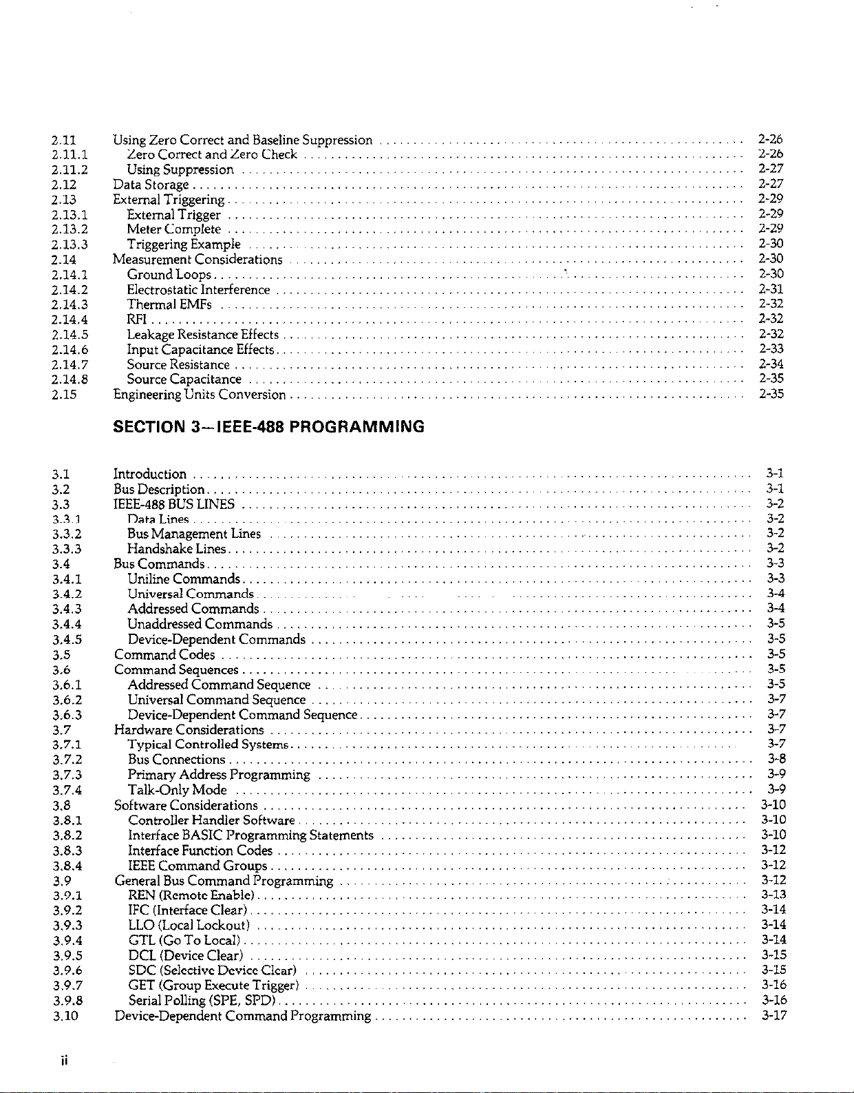
SECTION 3-IEEE-488 PROGRAMMING
.......
.......
......
......
......
......
......
......
......
......
......
......
......
.....
.......
.......
.......
.......
.......
.......
.......
.......
.......
.......
.......
.......
.......
3.1
3.2
3.3
3.3.1
3.3.2
3.3.3
3.4
3.4.1
3.4.2
3.4.3
3.4.4
3.4.5
3.5
3.4
3.6.1
3.6.2
3.6.3
3.7
3.7.1
3.7.2
3.7.3
3.7.4
3.8
3.8.1
3.8.2
3.8.3
3.8.4
3.9
3.9.1
3.9.2
3.9.3
3.9.4
3.9.5
3.9.6
3.9.7
3.9.8
3.10
Introduction
BusDescription
IEEE-488BUSLINES ..........................................................................
DataLines..
BusManagementLines ...........................................
HandshakeLines
BusCommands ...............................................................................
UniIineCommands
UniversalCommands ........................................................................
AddressedCommands .......................................................................
Unaddressedcommands .....................................................................
Device-DependentCommands
CommandCodes.. ...........................................................................
CommandSequences ..........................................................................
AddressedCommandSequence
UniversalCommandSequence
Device-DependentCommandSequence
Hardwareconsiderations.. ....................................................................
Typical Controlled Systems. ..................................................................
BusConnections ............................................................................
PrimaryAddressProgramming ...............................................................
Talk-OnlyMode
Softwareconsiderations
Controller Handler Software,
Interface BASIC Programming Statements
Interface Function Codes
IEEECommandGroups
General Bus Command Programming
REN(RemoteEnable) .......................................................................
IFC(InterfaceClear)
LLO(LocalLockout) .......................................................
GTL(GoToLocaI)
DCL(DeviceClear) ........................................................................
SDC (Selective Device Clear)
GET(GroupExecuteTrigger). ...............................................................
Serial Polling (WE, SPD)
Device-Dependent Command Programming
.................................................................................
...............................................................................
...............................................................................
............................................................................
..........................................................................
................................................................
...............................................................
................................................................
.........................................................
.
.....................
......................................................................
................................................................
.....
.....................................................................
........................................................................
.........................................................................
......................................
............................................
............................................... :
................................................................
.....................
................................................... 3-10
............................. ..........
........................ 3-2
..r
.
..............
............................. 3-16
.._ .............. 3-9
...............
...........
.............
.._
.............
3-l
3-l
3-2
3-2
3-2
3-3
3-3
3-4
3-4
3-5
3-5
3-5
3-5
3-5
3-7
3-7
3-7
3-7
3-8
3-9
3-10
3-10
3-12
3-12
3-12
3-13
3-14
3-14
3-14
3-15
3-15
3-16
3-17
ii
Page 7
3.10.1
3.10.2
3.10.3
3.10.4
3.10.5
3.10.6
3.10.7
3.10.8
3.10.9
3.10.10
3.10.11
3.10.12
3.10.13
3.10.14
3.10.15
3.10.16
3.10.17
3.10.18
3.11
3.11.1
3.11.2
3.11.3
3.12
Execute(X) ...... .................
Function (F) ........................
Range(R)
Zero Correct and Zero Check (Z and C)
Baseline Suppression (N) .............
Display Mode CD).
Reading Mode (B) ............ ......
Data Store Mode ...................
Voltage Source Value (V) .............
Voltage Source Operate (0) ..........
Calibration Value (A). ...............
Non-Volatile Memory Storage (L) .....
Data Format (G) ....................
Trigger Mode (T) ...................
SRQ Mode (M) and Status Byte Format
EOI and Bus Hold-Off Modes (K) ......
Terminator(Y) .....................
Status(u) .........................
Front Panel Messages ..................
BusError.. ........................
NumberError ......................
Trigger Overrun Error ...............
Bus Data Transmission Times ...........
..........................
..................
SECTION 4-APPLICATIONS
3-18
3-18
3-20
3-21
3-22
3-22
3-23
3-23
3-24
3-25
3-25
3-26
3-26
3-27
3-28
3-30
3-31
3-31
3-34
3-34
3-35
3-35
3-36
4.1
4.2
4.3
4.4
4.5
4.6
4.7
4.8
4.9
4.10
5.1
5.2
5.3
5.4
5.5
5.5.1
5.5.2
5.5.3
5.5.4
5.5.5
5.5.6
5.5.7
Introduction .................................................................
Insulation Resistance Measurements.
HighImpedanceVoItmeter
Low-Level Leakage Current Measurements
DiodeCharacterization
CapacitorLeakageMeasurements
CapacitanceMeasurement
Voltage Coefficients of High-Megohm Resistors
Static Charge Detection ........................................................
Using the Model 617 with External Voltage Sources
.....................................................
........................................................
......................................................
.............................................
........................................
...............................................
....................................
.................................
SECTION 5-PERFORMANCE VERIFICATION
Introduction ..............................
Environmental Conditions ..................
Initial Conditions ..........................
Recommended Test Equipment ...............
Verification Procedure ......................
Input Current Verification .................
Amps Verification .......................
Coulombs Verification. ...................
Volts Verification ........................
Ohms Verification .......................
Ohms Verification (200M0 and Gfl Ranges)
Voltage Source Verification. ...............
...........
...........
...........
...........
...........
...........
...........
...........
...........
...........
..........
..........
..........
..........
..........
..........
..........
..........
..............
..............
..............
..............
.............
..............
..............
..............
.............
.............
.............
.............
.............
.............
.............
.............
.............
4-l
4-l
4-5
4-5
4-7
4-8
4-E
4-10
4-12
4-12
5-l
5-l
5-l
5-l
5-2
5-2
5-2
5-3
5-5
5-6
5-6
5-8
iii
Page 8
SECTION 6-THEORY OF OPERATION
6.1
6.2
6.3
6.3.1
6.3.2
6.3.3
6.3.4
6.3.5
6.4
6.4.1
6.4.2
6.4.3
6.5
6.6
6.6.1
6.6.2
6.6.3
6.6.4
6.6.5
6.6.6
6.7
6.6
7.1
7.2
7.3
7.3.1
7.3.2
7.4
7.4.1
7.4.2
7.4.3
7.4.4
7.4.5
7.4.6
7.4.7
7.4.8
7.4.9
7.4.10
7.4.11
7.4.12
7.4.13
7.4.14
7.4.15
7.4.16
7.5
7.6
7.7
7.7.1
7.7.2
7.7.3
7.7.4
7.7.5
7.7.6
Introduction
Overall Functional Description
Input Preamplifier
Input stage ......................
Gain Stage. ......................
Output stage. ....................
Ohms Voltage Source
Zero Check ......................
Additional Signal Conditioning
Ranging Amplifier ................
Multiplexer and Buffer Amplifier ....
- 2V Reference Source. ............
A/D Converter.
Digital Circuitry
Microcomputer. ..................
Memory Elements. ................
Device Selection ..................
IEEE-486 Bus .....................
Input/Output Circuitry ............
Display Circuitry .................
Voltage source
Power Supplies
.......................
........
..................
....................
....................
.....................
.....................
.......
.......
.......
.......
.......
.......
.......
.......
.......
.......
.......
.......
.......
.......
.......
.......
.......
.......
.......
.......
.......
.......
.......
.......
.......
.......
.......
.......
.......
.......
.......
.......
.......
.......
.......
SECTION 7-MAINTENANCE
Introduction..
LineVoltageSelection
FuseReplacement
Lim Fuse .................................................................................
COMFuse ................................................................................
Calibration
Recommended Calibration Equipment. ........................................................
EnvironmentalConditions ..................................................................
WarmUpPeriod ..........................................................................
CalibrationJumper
Front Panel Calibration .....................................................................
IEEE-488 Bus Calibration. ...................................................................
Calibration Sequence .......................................................................
InputOffsetAdjustment ....................................................................
InputCurrentAdjustment ...................................................................
Pemxnent Storage of Calibration Parameters
AmpsCalibration.. .......................................................................
Coulombs Calibration ...................................................................
VoltsCalibration.. ........................................................................
OhmsCalibration .........................................................................
Voltage Source Calibration ..................................................................
Additional Calibration Points ................................................................
Special Handling of Static-Sensitive Devices
Disassembly Instructions
Troubleshooting
RecommendedTestEquipment ...............................................................
PowerUpSelfTest .........................................................................
SelfDiagnosticProgram ....................................................................
PowerSupplyChecks ......................................................................
RelayConfiguration ........................................................................
Ranging Amplifier Gain Configuration ........................................................
..............................................................................
........................................................................
............................................................................
.................................................................................
.........................................................................
...................................................
......................................................
......................................................................
.............................................................................
......
......
......
......
......
......
......
......
......
......
......
......
......
......
......
......
......
......
......
......
......
......
......
......
......
......
......
......
......
......
6-l
6-1
6-l
6-3
6-3
6-3
6-6
6-7
6-7
6-7
6-8
6-9
6-9
6-11
6-11
6-11
6-u
6-11
6-12
6-12
6-13
6-14
7-l
7-1
7-2
7-Z
7-2
7-2
7-2
7-3
7-3
7-3
7-3
7-4
7-5
7-5
7-s
7-6
7-4
7-7
7-8
7-a
7-10
7-10
7-U
7-12
7-12
7-12
7-14
7-14
7-14
7-15
7-15
iv
Page 9
7.7.7
7.7.8
7.7.9
7.7.10
7.7.11
7.8
7.9
A/DConverterandDisplay .................................
Input and Ranging Amplifiers
DigitalCircuitry.. .................................................
Display Board
VoltageSource ..............................................................
InputStageBalancingProcedure
Handling and Cleaning Precautions
...........................................
.............................................
................................................................
..........................................
SECTION 8--REPLACEABLE PARTS
........
..... ..
............
..... .. .........
.,
......................
.....
...
... 7-16
.....
... 7.17
.....
...
7.17
7-17
7-17
7-17
7-18
8.1
8.2
a.3
a.4
a.5
8.6
Introduction ......................................
Electrical Parts Lists
Mechanical Parts
Ordering Information
Factory Service..
Component Layout Drawings and Schematic Diagrams
................................
..................................
..............................
.................................
......
......
......
......
8-l
8-l
8-l
8-l
8-l
8-l
Page 10
LIST OF ILLUSTRATIONS
2-l
2-2
2-3
2-4
2-5
2-6
2-7
2-a
2-9
2-10
2-11
Z-12
2-13
2-14
2-15
2-16
2-17
2-18
2-19
2-20
2-21
2-22
2-23
2-24
2-25
2-26
2-27
2-28
2-29
Model617FrontPanel..........................................
Model617RearPanel
Input Connector Configuration
Connections For Voltage Measurements
Meter Loading Considerations
Unguarded Circuit
GuardedCircuit
Guarded Input Connections
CurrentMeasurements
Voltage Burden Considerations.
Coulombs Connections
Resistance Measurement Connections
Voltage Source Connections
V/l Resistance Measurement Connections
Typical 2V Analog Output Connections
Typical Preamp Out Connections.
Electrometer Input Circuitry (AmpsMode)
Shielded Fixture Construction
“Transdiode” Logarithmic Current Configuration
Non-Decade Current Gains
Equivalent Input Impedance with Zero Check Enabled.
External Trigger Pulse Specifications
Meter Complete Pulse Specifications
Exlemal Triggering Example
Multiple Ground Points Create Ground Loop
Eliminating Ground Loops
Leakage Resistance Effects
Input Capacitance Effects.
Simplified Model of Source Resistance and Source Capacitance Effects
..........................................
..................................
...........................
.................................
...........................................
...............................................
.....................................
..........................................
..................................
.........................................
.............................
.....................................
..........................
...........................
................................
............... .........
....................................
...................
......................................
...............
..............................
..............................
.....................................
......................
......................................
.......................................
.......................................
^.
..........
..........
..........
..........
..........
..........
..........
..........
..........
..........
..........
..........
..........
..........
..........
2-2
2-7
2-8
2-9
2-10
2-13
2-13
2-14
2-16
2-17
2-18
2-31
2-33
2-34
2-34
3-l IEEE Bus Configuration
3-2
3-3
3-4
3-5
3-6
3-7 617 Rear Panel IEEE Connector.
3-B Contact Assignments
3-9 General Data Format
3-10 SRQ Mask and Status Byte Format.
3-11 UO Status Word and Default Values.
3-12
3-13 U2 Status (Data Condition) Format
vi
IEEE Handshake Sequence.
Commands Groups
System Types
IEEE-488 Connector
IEEE-488 Connections
Ul Status (Error Condition) Format
.......
.......
.......
.......
.......
.......
.......
.......
.......
.......
.......
Page 11
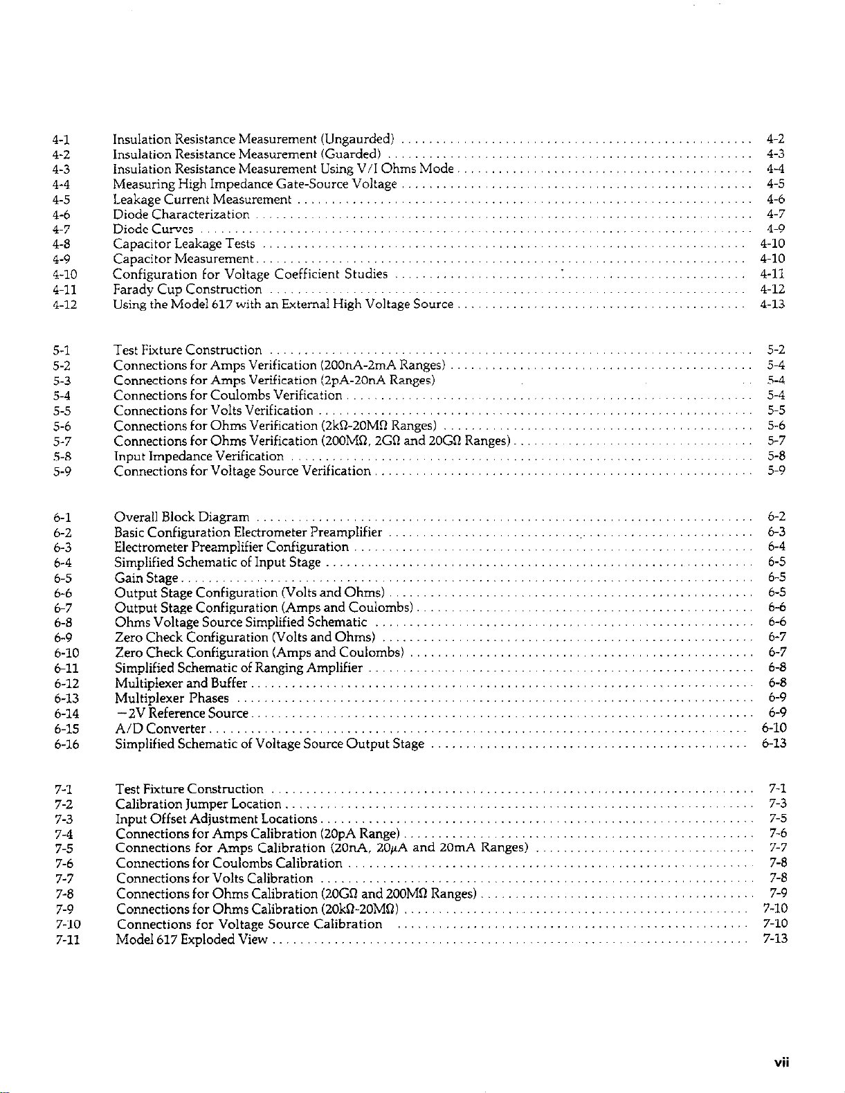
4-l
4-2
4-3
4-4
4-5
4-6
4-7
4-8
4-9
4-10
4-11
4-12
Insulation Resistance Measurement (Ungaurded)
..........
Insulation Resistance Measurement (Guarded) ............
Insuiation Resistance Measurement Using V/I Ohms Mode.
Measuring High Impedance Gate-Source Voltage ..........
Leakage Current Measurement .........................
Diode Characterization ...............................
DiodeCurves.. .....................................
Capacitor Leakage Tests
..............................
Capacitor Measurement. ..............................
Configuration for Voltage Coefficient Studies ...........
Farady Cup Construction .............................
Using the Model 617 with an External High Voltage Source
......
......
......
......
......
......
5-l
5-2
5-3
5-4
5-5
5-6
5-7
5-8
5-9
6-l
6-2
6-3
b-4
b-5
6-b
6-7
6-8
6-9
6-10
6-11
6-12
b-13
b-14
b-15
6-16
Test Fixture Construction
.....................................
Connections for Amps Verification (200nA-2mA Ranges) ...........
Connections for Amps Verification (2pA-20nA Ranges) ............
Connections for Coulombs Verification ..........................
Connections for Volts Verification
..............................
Connections for Ohms Verification (2kQ-20MQ Ranges) ............
Connections for Ohms Verification (200MR. 2G0 and 20Gfl Ranges).
Input Impedance Verification ..................................
Connections for Voltage Source Verification ......................
Overall Block Diagram ............................
Basic Configuration Electrometer Preamplifier
.........
Electrometer Preamplifier Configuration ..............
Simplified Schematic of Input Stage
..................
GainStage .......................................
Output Stage Configuration (Volts and Ohms) .........
Output Stage Configuration (Amps and Coulombs)
.....
Ohms Voltage Source Simplified Schematic ...........
Zero Check Configuration (Volts and Ohms) ..........
Zero Check Configuration (Amps and Coulombs) ......
Simplified Schematic of Ranging Amplifier ............
Multiplexer and Buffer
.............................
Multiplexer Phases ...............................
-2V Reference Source.
............................
A/D Converter. ..................................
Simplified Schematic of Voltage Source Output Stage ...
..........
..........
..........
.., ..,
...................
...................
6-2
6-3
b-4
b-5
6-5
6-5
6-b
b-6
b-7
6-7
b-8
6-8
6-9
6-9
b-10
6-13
7-l
7-2
7-3
7-4
7-5
7-6
7-7
7-8
7-9
7-10
7-11
Test Fixture Construction .......................................
Calibration Jumper Location .....................................
Input Offset Adjustment Locations.
...............................
Connections for Amps Calibration (20pA Range) ....................
Connections for Amps Calibration (20nA. 20/rA and 20mA Ranges)
Connections for Coulombs Calibration ............................
Connections for Volts Calibration ................................
Connections for Ohms Calibration (20GQ and 2OOMO Ranges) .........
Connections for Ohms Calibration (2Ok%ZOMQ)
Connections for Voltage Source Calibration
....................
.....................
Model617ExplodedView .......................................
......
......
......
......
......
......
......
......
......
7-l
7-3
7-5
7-6
7-7
7-a
7-8
7-9
7-10
7-10
7-13
vii
Page 12

8-l Electrometer Board, Component Location Drawing.
g-2
8-3
Mother Board, Component Location Drawing
Display Board, Component Location Drawing
8-4 Electrometer Board, Schematic Diagram
8-5
Mother Board, Schematic Diagram.
8-6 Display Board, Schematic Diagram
................
................
.......
.......
............
..
8-11
g-13
8-17
8-19
8-21
8-27
. .
VW
Page 13
LIST OF TABLES
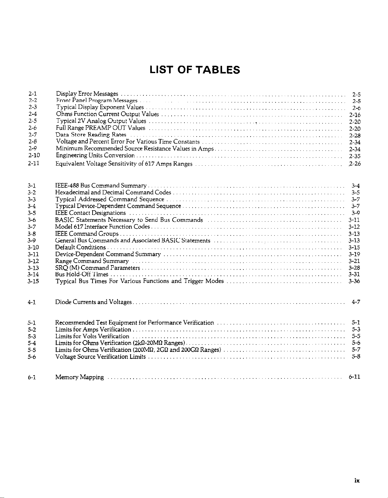
2-l
2-2
2-3
2-4
2-5
2-6
2-7
2-8
2-9
2-10
2-11
3-l
3-2
3-3
3-4
3-5
3-6
3-7
3-a
3-9
3-10
3-11
3-12
3-13
3-14
3-15
Display Error Messages .................................
Front Panel Program Messages
Typical Display Exponent Values ................
Ohms Function Current Output Values
Typical 2V Analog Output Values ........................
Full Range PREAMP OUT V&es ......
Data Store Reading Rates ...........
Voltage and Percent Error For Various Time Constants
Minimum Recommended Source Resistance Values in Amps. ..
Engineering Units Conversion ..................
Equivalent Voltage Sensitivity of 617 Amps Ranges
IEEE-488 Bus Command Summary. .........................
Hexadecimal and Decimal Command Codes
Typical Addressed Command Sequence
Typical Device-Dependent Command Sequence.
IEEE Contact Designations ................................
BASIC Statements Necessary to Send Bus Commands
Model 617Interface Function Codes. ........................
IEEE Command Groups.
General Bus Commands and Associated BASIC Statements
Default Conditions.
Device-Dependent Command Summary
Range Command Summary ...............................
SRQ (M) Command Parameters ............................
Bus Hold-Off Times
Typical Bus Times For Various Functions and Trigger Modes
......................................
......................................
............
.. ........... ....
..................................
.. .... .....
...
......... ... ..
........... ....
.......
.....
.........
..................
............. ......
..............
.......
.....
.....................
......
......
......
......
......
......
......
......
......
......
......
3-4
3-5
3-7
3-7
3-9
3-11
3-12
3-13
3-13
3-15
3-19
3-21
3-28
3-31
3-36
4-l
5-l
5-2
5-3
5-4
5-5
5-6
6-l
Diode Currents and Voltages.
Recommended Test Equipment for Performance Verification
Limits for A mps Verlflcatlon
Limits for Volts Verification
Limits for Ohms Verification (2kn-2OMa Ranges).
Limits for Ohms Verification (2COMn, 2Gn and 2OOGil Ranges)
Voltage Source Verification Limits
MemoryMapping .._......................................................
......
......
......
......
4-7
5-l
5-3
5-5
5-b
5-7
5-8
6-11
ix
Page 14
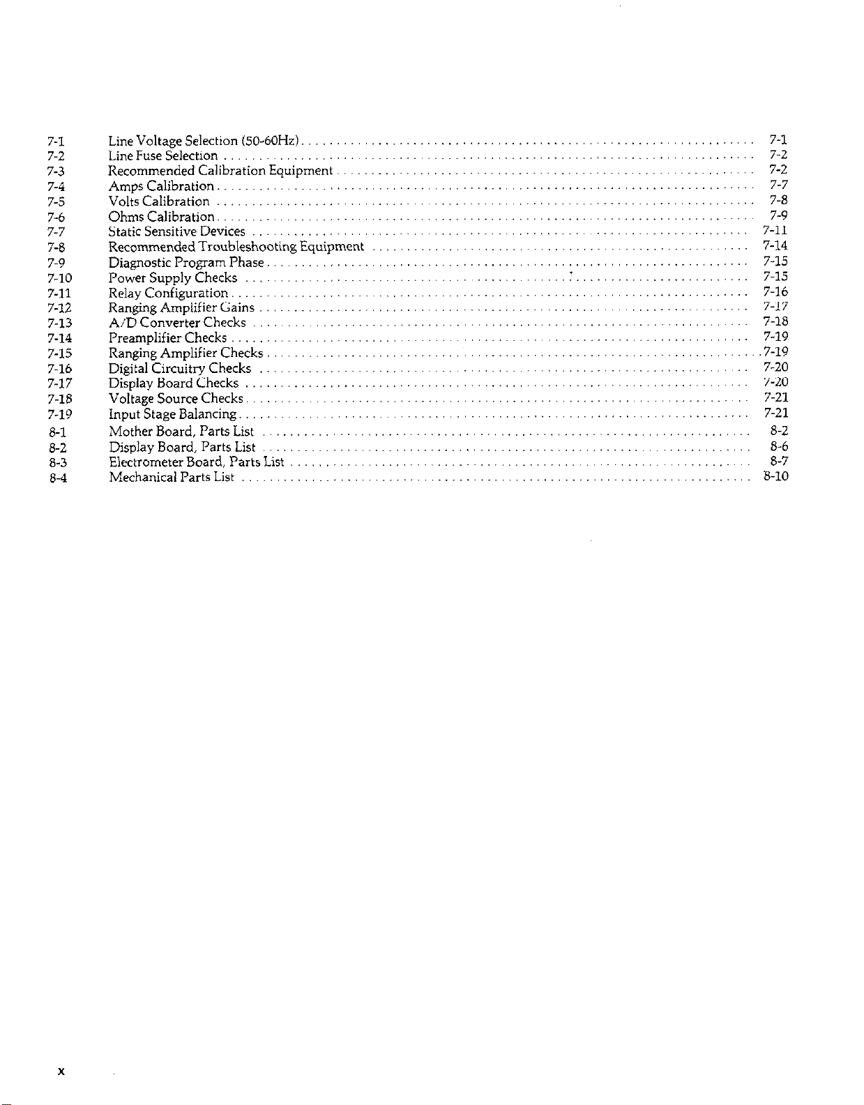
7-1
7-2
7-3
7-4
7-5
7-6
7-7
7-8
7-9
7-10
7-11
7-12
7-13
7-14
7-15
7-16
7-17
7-18
7-19
8-l
a-2
8-3
8-4
Line Voltage Selection (50-60Hz).
LineFuseSelection
Recommended Calibration Equipment
AmpsCalibration .............................................................................
VoltsCalibration..
OhmsCalibration .............................................................................
StaticSensitiveDevices
Recommended Troubleshooting Equipment
DiagnosticProgramPhase
PowerSupplyChecks
Relayconfiguration
Ranging Amplifier Gains
A/DConverterChecks
Preamplifierchecks .......................................................................... 7-19
RangingAmplifierChecks.......................................................................7-1 9
DigitalCircuitryChecks
DisplayBoardChecks
VoltageSourceChecks
InputStageBalancing .........................................................................
MotherBoard,PartsList .......................... .... ...... .......... .. ....
DisplayBoard,PartsList
Electrometer Board, Parts List
Mechanicall’artsList
............................................................................
........ .. ........................ ........ .......
..... . ...........................
..............................................
.......................................................................... 7-16
......... ......... ............. .......... .......
................ .........................
........ ... ........
........................................................................ 7-21
......................... .. ...... ..... ..... ....
....... ............
...........................
........................ ...... .. ...... ......... ......
...............
..................................................................... 7-15
... ......... ..........
........ ......
... .........
........... .....
.................. ........ ......
....................................
................................
... ...
........ ...... .............
... ......
.........................
.
........................
................................
..........
.................
..............
..............
...... ....
.,
........
....
7-l
7-2
7-2
7-7
7-8
7-9
7-11
7-14
7-15
7-17
7-18
7-20
7-20
7-21
8-2
8-6
8-7
S-10
x
Page 15

SAFETY PRECAUTIONS
The following safety precautions should be observed before operating the Model 617
This instrument is intended for use by qualified personnel who recognize shock hazards and are familiar with the
safety precautions required to avoid possible injury. Read over the manual carefully before operating this instrument.
Exercise extreme caution when a shock hazard is present at the instrument’s input. The American National Standards Institute (ANSI) states that a shock hazard exists when voltage levels greater than 30V rms or 42.4V peak
are present. A good safety practice is to expect that a hazardous voltage is present in any unknown circuit before
measuring.
Do not exceed 5oOV peak between input low and earth ground. Do not connect PREAh4P OUT, COM, OI
2V ANALOG OUTPUT to earth ground when floating input.
Inspect the test leads for possible wear, cracks or breaks before each use. If any defects are found, replace with test
leads that have the same measure of safety as those supplied with the instrument.
For optimum safety do not touch the test leads or the instrument while power is applied to the circuit under test.
Turn the power off and discharge all capacitors, before connecting or disconnecting the instrument.
Do not touch any object which could provide a current path to the common side of the circuit under test or power
line (earth) ground. Always make measurements with dry hands while standing on a dry, insulated surface,
capable of withstanding the voltage being measured.
Do not exceed the instrument’s maximum allowable input as defined in the specifications and operation section.
Safe operation and good measurement practice dictates use of an external resistor when necessary to limit input
currents to less than 30mA.
Page 16
SECTION 1
GENERAL INFORMATION
1.1 INTRODUCTION
The Keithley Model 617 Programmable Electrometer is a
highly sensitive instrument designed to measure voltage, current, charge, and resistance. Two forms of resistance
measurements are included in the standard configuration: a
constant current method, and a constant voltage method that
uses a built in voltage source for greater sensitivity. The
measuring range of the Model 617 is between 1OpV and 200V
for voltage measurements, O.lfA and 2OmA in the current
mode, O.ln and 200GO (up to 1OlQ using the built in voltage
source), and lOfC and 20°C in the coulombs mode. The very
high input impedance and extremely low input offset current
allow accurate measurement in situations where many other
instruments would have detrimental effects on the circuit being measured. A 4% digit display and standard IEEE-488 interface give the user easy access to instrument data.
1.2 FEATURES
Some important Model 617 features include:
l 4% Digit Display-An easy to read front panel LED display
includes a 4% digit mantissa plus a two-digit alpha or
numeric exponent.
l Autoranging-Included for all functions and ranges.
l Digital Calibration-The instrument may be digitally
calibrated from the front panel or over the IEEE-488 bus.
l Zero Correct-A front panel zero correct control allows the
user to cancel any offsets.
l Baseline Suppression-One button suppression of a
baseline reading is available from the front panel or over the
IEEE-488 bus.
l One-shot Triggering-A front panel control for triggering
one-shot readings from the front panel is included.
l Isolated IOOV Voltage Source-A built in 1OOV scwrce is
isolated from the electrometer section. The voltage source is
programmable in 50mV steps.
l Selectable Guarding-A selectable driven cable guard is in-
cluded to optimize speed.
l Standard IEEE-488 Interface-The interface allows full bus
programmable operation of the Model 617.
l Analog Outputs-Both preamp and 2V full range analog
outputs are included on the rear panel.
l 100~Point Data Store-An internal buffer that can store
up to 100 readings is accessible from either the front panel
or over the IEEE-488 bus.
l Minimum and maximum data points can be stored and are
accessible from the front panel or over the IEEE-488 bus.
1.3 WARRANG INFORMATION
Warranty information for your Model 617 may be found inside the front cover of this manual. Should you need to use
the warranty, contact your Keithley representative or the factory for information on obtaining warranty service. Keithley
Instruments, Inc. maintains service facilities in the United
States, West Germany, Great Britain, France, the
Netherlands, Switzerland, and Austria. Information concerning the operation, application, or service of your instrument
may be obtained from the applications engineer at any of
these locations.
1.4 MANUAL ADDENDA
Information concerning improvements or changes to the instrument which occur after the printing of this manual will be
found on a” addendum sheet included with this manual.
Please be sure that you read this information before attempting to operate or service your instrument.
1.5 SAFETY SYMBOLS AND TERMS
The following safety symbols and terns are used in this
manual and found on the instrument:
The A
should refer to the operating instructions in this manual for
further details.
The WARNING heading as used in this manual explains
dangers that might result in personal injury or death. Always
read the associated information very carefully before performing the indicated procedure.
The CAUTION heading used in this manual explains hazards
that could damage the instrument. Such damage may in-
validate the warranty.
symbol on the instrument indicates that the user
l-l
Page 17
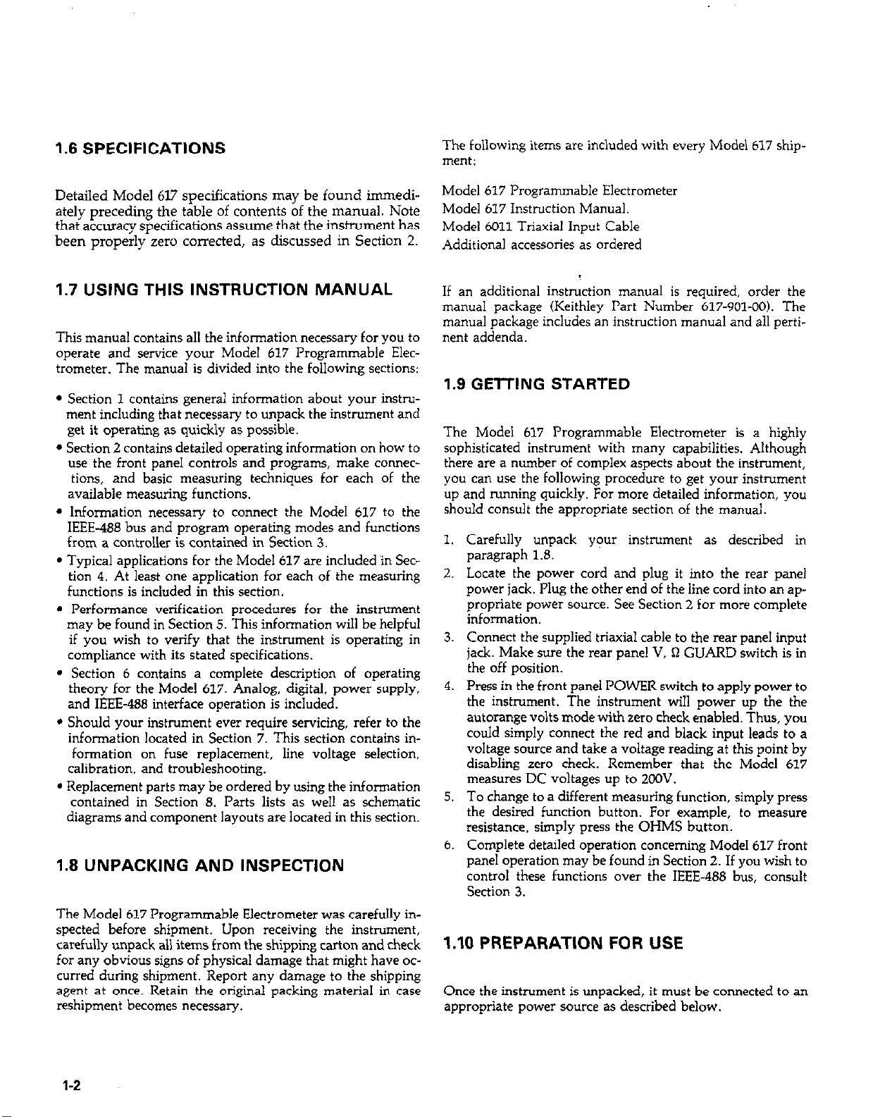
1.6 SPECIFICATIONS
The following items aw included with every Model 617 shipment:
Detailed Model 617 specifications may be found immedi-
ately preceding the table of contents of the manual. Note
that accuracy specifications assume that the insinxnent has
been properly zero corrected, as discussed in Section 2.
1.7 USING THIS INSTRUCTION MANUAL
This manual contains all the information necessary for you to
operate and service your Model 617 Programmable Elec-
trometer. The manual is divided into the following sections:
l Section 1 contains general information about your instru-
ment including that necessary to unpack the instrument and
get it operating as quickly as possible.
l Section 2 contains detailed operating information on how to
use the front panel controls and programs, make connec-
tions, and basic measuring techniques for each of the
available measuring functions.
l Information necessary to connect the Model 617 to the
IEEE-488 bus and program operating modes and functions
from a controller is contained in Section 3.
l Typical applications for the Model 617 are included ‘in Sec-
tion 4. At least one application for each of the measuring
functions is included in this section.
l Performance verification procedures for the instrument
may be found in Section 5. This information will be helpful
if you wish to verify that the instrument is operating in
compliance with its stated specifications.
l Section 6 contains a complete description of operating
theory for the Model 617. Analog, digital, power supply,
and IEEE-488 interface operation is included.
l Should your instrument ever require servicing, refer to the
information located in Section 7. This section contains in-
formation on fuse replacement, line voltage selection,
calibration. and troubleshooting.
l Replacement parts may be ordered by using the information
contained in Section 8. Parts lists as well as schematic
diagrams and component layouts are located in this section.
1.8 UNPACKING AND INSPECTION
The Model 617 Programmable Electrometer was carefully in-
spected before shipment. Upon receiving the instrument,
carefully unpack all items from the shipping carton and check
for any obvious signs of physical damage that might have oc-
curred during shipment. Report any damage to the shipping
agent at once. Retain the original packing material in case
reshipment becomes necessary.
Model 617 Programmable Electrometer
Model 617 Instruction Manual.
Model 6011 Triaxial Input Cable
Additional accessories as ordered
If an additional instruction manual is required, order the
manual package (Keithley Part Number 617-901-W). The
manual package includes an instruction manual and all perti-
nent addenda.
1.9 GElTING STARTED
The Model 617 Programmable Electrometer is a highly
sophisticated instrument with many capabilities. Although
there are a number of complex aspects about the instrument,
you can use the following procedure to get your instrument
up and running quickly. For more detailed information, you
should consult the appropriate section of the manual.
1.
Carefully unpack your instrument as described in
paragraph 1.8.
2.
Locate the power cord and plug it into the rear panel
power jack. Plug the other end of the line cord into an appropriate power source. See Section 2 for more complete
information.
3.
Connect the supplied triaxial cable to the rear panel input
jack. Make sure the rear panel V, R GUARD switch is in
the off position.
4.
Press in the front panel POWER switch to apply power to
the instrument. The instrument will power up the the
autorange volts mode with zero check enabled. Thus, you
could simply connect the red and black input leads to a
voltage source and take a voltage reading at this point by
disabling zero check. Remember that the Model 617
measures DC voltages up to 2COV.
5.
To change to a different measuring function, simply press
the desired function button. For example, to measure
resistance. simply press the OHMS button.
6.
Complete detailed operation concerning Model 617 front
panel operation may be found in Section 2. If you wish to
control these functions over the IEEE-488 bus, consult
Section 3.
1.10 PREPARATION FOR USE
Once the instrument is unpacked, it must be connected to an
appropriate power source as described below.
l-2
Page 18

Line Power-The Model 617 is designed to operate from
105-125V or 210-250V power sources. A special power transformer may be installed for 90-1lOV and 195-235V ranges.
The factory set range is marked on the rear panel of the in-
strurnent. Note that the line plug is designed to mate with the
supplied 3-wire power cord.
CAUTION
Do not attempt to operate the instrument
on a supply voltage outside the indicated
range, or instrument damage might occur.
Line Voltage Selection-The operating voltage of the instrument is internally selectable. Refer to Section 7 for the procedure to change or verify the line voltage setting,
Line Frequency-The Model 617 may be operated from either
50 or 60Hz power sources.
IEEE-488 Primary Address-If the Model 617 is to be programmed over the IEEE-488 bus, it must be set to the arrect
primary address. The primary address is set to 27 at the factory, but it may be programmed from the front panel as
described in Section 3.
1.11 REPACKING FOR SHIPMENT
Before shipping, the instrument should be carefully packed in
its original packing material.
Model 6011 and 6011-10 Triaxial Cables-The Model 6011 is
made up of 3 feet of triaxial cable that is terminated with a
trim plug on one end and 3 alligator clips on the other end.
The Model 6011-10 is a similar cable 10 feet in length. Note
that the Model 6011 is supplied with the Model 617.
Model 6012 Triax to UHF Adapter-The Model 6012 allows
the Model 617 to be used with accessories having UHF type
co”nectors.
Model 6lOlA Shielded Test Lead-The Model 610lA is a
straight through probe and shielded lead equipped with 0.8m
(3O”) of shielded low noise cable terminated by a Tefloninsulated UHF connector. The Model 6012 must be used to
adapt the Model 6101A to the Model 617 triaxial input.
Model 6103C Voltage Divider Probe-The Model 6103C extends Model 617 voltage measurement range to 30kV. The
Model 6103C has a division ratio of 1OOO:l with a nominal
accuracy of 5%. The probe has an input resistance of 4.5 x
10110 and is equipped with a UHF male plug. The Model 6012
adapter must be used to connect the Model 6103C to the
Model 617.
Model 6104 Test Shield-The Model 6104 facilitates
resistance, voltage, or current measurements with either 2- or
3-terminal guarded connections at voltages up to 1200V. The
Model 6104 provides excellent electrostatic shielding and high
isolation resistance. Clips plug into banana jacks, allowing
custom connections. The Model 6104 has a BNC camector
on one side and binding posts on the other. The Model 6147
adapter (below) is required to connect the Model 6104 to the
Model 617.
If the instrument is to be returned to Keithley Instruments for
repair or calibration, include the following:
Write ATTENTION REPAIR DEPARTMENT on the shipping label.
Include the warranty status of the instrument.
Complete the service form at the back of this manual.
1.12 ACCESSORIES
The following accessories are available to enhance Model 617
capabilities.
Models 1019A and 1019s Rack Mounting Kits-The Model
1019A is a fiied or stationary rack mounting kit with two
front panels provided to enable either single or dual side-byside mounting of the Model 617 or other similar Keithley instrument. The Model 1019s is a similar rack mounting kit
with a sliding mount configuration.
Model 6105 Resistivity Chamber-The Model 6105 is a
guarded test fixture for measuring voltage and surface
resistivities. The unit assures good electrostatic shielding and
high insulation resistance. The complete system requires the
use of an external high-voltage supply such as the Model 247
as well as the Model 617. Volume resistivity up to 105Q/cm
and surface resistivity up to 1018Q can be measured in accordance with ASTM test procedures. Sheet samples 64 to
102mm (2Yz X 4”) in diameter and up to 6.4mm (IA”)
thickness can be accommodated. Excitation voltages up to
1OOOV may be used.
Model 6146 Triax Tee Adapter-The Model 6147 allows the
simultaneous connection of two triaxial cables to the single
triaxial input of the Model 617.
Model 6147 Triax to BNC Adapter-The Model 6147 allows
the Model 617 input to be connected to accessories having
BNC connectors.
Model 6171 and 6172 3 Lug-to-2 Lug Adapters-The Model
6171 is a 3 lug male-to-2 lug female triaxial adapter, while the
Model 6172 is a 2 lug male-to-3 lug female triaxial adapter.
1-3
Page 19
Model 7008 IEEE-488 Cables-The Model 7008 cables are
designed to connect the Model 617 to the IEEE-466 bus and
are available in two similar versions. The Model 7008-3 is
0.9m (3 ft.) in length, while the Model 7008-6 is 1.&n (6 ft.)
long. Each cable is terminated with a standard IEEE-488 connector on each end, and each connector is equipped with two
metric SCTBWS.
Model 7024 Triaxial Cables-The Model 7024 cables are
similar units with male triaxial connectors on each end. The
Model 7024-l is 0.3m (1 ft:) in length, while the Models
7024-3 and 7024-10 are 0.9m (3 ft.) and 3.0m (10 ft.) long
respectively. These cables may be used to connect the Model
617 signal input to other equipment having similar triaxial
connections.
Model 7023 Female Triaxial Connector-The Model 7023 is a
chassis mount connector that mates with the Models 6011 and
7024 triaxial cables.
Model 8573 IEEE-488 Interface for the IBM PC-The Model
8573 allows the Model 617 to be connected to and controlled
from the IBM PC via the IEEE-488 bus.
1-4
Page 20
SECTION 2
OPERATION
2.1 INTRODUCTION
Operation of the Model 617 may be divided into two general
categories: front panel operation and IEEE-488 bus operation.
This section contains information necessary to use the instrument on a front-panel basis. Note that many of these func-
tions can also be programmed over the IEEE-488 bus, as
described in Section 3.
The following paragraphs contain a complete description of
Model 617 front panel operation. First a complete description
of each front and rear panel function is presented. Next the
complete procedure for each of the measuring functions is
presented, followed by a description of the built in voltage
source. Finally, the analog output and guard functions are
described along with a method to apply external feedback.
2.2 POWER UP PROCEDURE
Use the procedure below to connect the Model 617 to line
power and power up the instrument.
1. Connect the female end of the power cord to the AC receptacle on the rear panel of the instrument. Connect the other
end of the cord to a grounded AC outlet.
switch. The switch will be at the inner most position when
the instrument is turned on.
3. The instrument will power up in the volts function, in the
autorange mode aqd with zero check enabled, as indicated
by the associated front panel LEDs. All other LEDs will be
off when the instrument is first turned on.
2.3 POWER UP SELF TEST AND DISPLAY
MESSAGES
The RAM memory is automatically tested as part of the
power up procedure. If a RAM memory error occurs, the “rr”
message will remain on the display. If the instrument was not
able to read the stored calibration constants and configuration, the decimal points in the two exponent digits will flash.
If such errors occur, the instrument may be partially or completely inoperative. Refer to Section 7 for more complete
details.
A power up self test may be run and the software revision
level may be displayed by pressing and holding the TRIG but-
ton when the unit is first turned on. During the test, all front
panel LEDs and the display segments will turn on as in the example below:
WARNING
The Model 617 is equipped with a 3-wire
power cord that contains a separate ground
wire and is designed to be used with
grounded outlets. When proper connec-
tions are made, instrument chassis is con-
nected to power line ground. Failure to use
a grounded outlet may result in personal in-
jury or death because of electric shock.
CAUTION
Be sure that the power line voltage agrees
with the indicated range on the rear panel
of the instrument. Failure to observe this
precaution may result in instrument
damage. If necessary, the line voltage may
be changed as decribed in Section 7.
2. Turn on the power by pressing in the front panel POWER
The instrument will then display the software revision level
when TRIG is released, for example:
E.4
The instrument will then enter the diagnostic mode, which is
used as an aid in troubleshooting problems within the instrument. See Section 7 for details. The power must be turned off
to remove the instrument from the diagnostic mode.
NOTE
If the instrument is still under warranty (less
than one year from the date of shipment), and
problems develop, it should be returned to
Keithley Instruments for repair. See paragraph
1.11 for details on returning the instrument.
2-I
Page 21
J
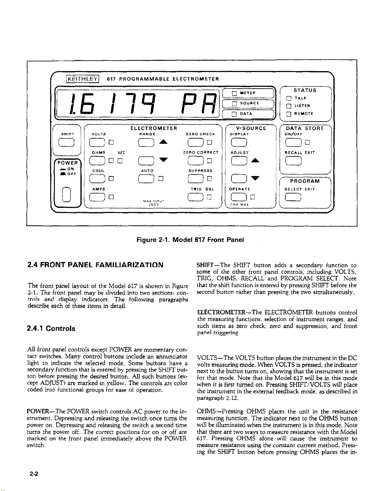
Figure 2-1. Model 617 Front Panel
\
PROGRAM PROGRAM
SELECT EXIT SELECT EXIT
0 0
i, i,
2.4 FRONT PANEL FAMILIARIZATION
The front panel layout of the Model 617 is shown in Figure
2-1. The front panel may be divided into two sections: controls and display indicators. The following paragraphs
describe each of these items in detail.
2.4.1 Controls
All front panel controls except POWER are momentary con-
tact switches. Many control buttons include an annunciator
light to indicate the selected mode. Some buttons have a
secondary function that is entered by pressing the SHIFT button before pressing the desired button. All such buttons (except ADJUST) are marked in yellow. The controls are color
coded into functional groups for ease of operation.
POWER-The POWER switch controls AC power to the in-
strument. Depressing and releasing the switch once turns the
power on. Depressing and releasing the switch a second time
turns the power off. The correct positions for on or off are
marked on the front panel immediately above the POWER
switch.
SHIFT-The SHIFT button adds a secondary function to
some of the other front panel controls, including VOLTS,
TRIG, OHMS, RECALL and PROGRAM SELECT. Note
that the shift function is entered by pressing SHIFT before the
second button rather than pressing the two simultaneously.
ELECTROMETER-The ELECTROMETER buttons control
the measuring functions, selection of instrument ranges, and
such items as zero check, zero and suppression, and front
panel triggering.
VOLTS-The VOLTS button places the instrument in the DC
volts measuring mode. When VOLTS is pressed, the indicator
next to the button turns on, showing that the instrument is set
for that mode. Note that the Model 617 will be in this mode
when it is first turned on. Pressing SHIFT/VOLTS will place
the instrument in the external feedback mode, as described in
paragraph 2.12.
OHMS--Pressing OHMS places the unit in the resistance
measuring function. The indicator next to the OHMS button
will be illuminated when the instrument is in this mode. Note
that there are two ways to measure resistance with the Model
617. Pressing OHMS alone will cause the instrument to
measure resistance using the constant current method. Pressing the SHIFT button before pressing OHMS places the in-
2-2
Page 22
strument in the V/I mode of resistance measurement, as
described in paragraph 2.8. The V/I indicator will light when
the instrument is in this mode.
COUL-The Model 617 may be set up to measure charge by
pressing the COUL button. The indicator next to the COUL
button will illuminate when the instrument is set for this
mode.
AMPS-Pressing AMPS switches the instrument to the
current-measuring function. The AMPS indicator will turn
on when the instrument is in this mode.
RANGE-These two buttons allow you to increment or
decrement the range the instrument is in. Pressing the up ar-
row button will move the instrument up one range each time
it is operated, while the down arrow button will move the instrument down range one increment each time it is pressed.
Note that pressing either of these buttons will cancel
autorange if that mode was previously selected. The display
mantissa will remain blank until the first reading is ready to
be displayed.
AUTO-The AUTO button places the instrument in the auto
range mode. While in this mode, the Model 617 will switch to
the best range to measure the applied signal. Note that the instrument will be in the autorange mode when it is first turned
on. Autoranging is available for all functions and ranges.
Autoranging may be cancelled either by pressing the AUTO
button or one of the two RANGE buttons.
ZERO CHECK-The zero check mode is used in conjunction
with the ZERO CORRECT control to cancel any offsets
within the instrument and is also used as a standby mode.
Pressing ZERO CHECK once will enable this mode, as shown
by the associated indicator light. When zero check is enabled,
the electrometer input circuit configuration changes (see
paragraph 2.11). No readings can be be taken with zero
check enabled. Pressing ZERO CHECK a second time will
disable this mode. Zero check should be enabled when
making connections or when changing functions.
ZERO CORRECT-The zero correct mode works with zero
check to cancel electrometer offsets. If zero check is enabled,
pressing ZERO CORRECT will store a new value that will be
used to cancel any offset. If the range is changed while zero
correct is enabled, the stored value will be scaled accordingly.
Zero correct may be cancelled by pressing the ZERO CORRECT button a second time. More information on using zero
correct may be found in paragraph 2.11.
may be disabled by pressing the SUPRESS button a second
time, and is cancelled if the function is changed.
TRIG-The TRIG button allows you to enter the one-shot
trigger mode and trigger single readings from the front panel.
To enter the one-shot mode, press SHIFT then TRIG. The
SGL indicator light will show that the instrument is in the
one-shot mode. Each time the TRIG button is pressed, a
single reading will be processed and displayed. The displayed
reading will flash when the TRIG button is pressed. The oneshot trigger mode can be cancelled by pressing SHIFT then
TRIG a second time. Additional information on triggering
may be found in paragraphs 2.13 and 3.10.14.
V-SOURCE-These buttons control the internal 2100V
source within the instrument. More information on the using
the voltage source is located in paragraph 2.8.
DISPLAY-The DISPLAY button toggles the front panel
display between the voltage source and the present display
mode (electrometer or data store). Pressing DISPLAY once
will switch the display from the present mode to the source
mode, as indicated by the LEDs adjacent to the display (more
information on the display is located in paragraph 2.4.2).
Pressing DISPLAY again will return the display to the
previous display mode.
ADJUST-These two buttons control the voltage source out-
put value. The up arrow button increases the voltage value in
50mV increments, while the down arrow decreases the
voltage source output in 5OmV increments. The values may
be scrolled by holding the desired ADJUST arrow in. The in-
strument will stop on the value currently displayed when the
button is released. The scrolling can be made more rapid by
pressing the SHIFT key before pressing the desire ADJUST
key. Note that the ADJUST keys are also used with certain
front panel programs, as described in paragraph 2.5. Note
that the maximum voltage values are +102.4V and
-102.35V.
OPERATE-The OPERATE button turns the actual voltage
source output on or off. Pressing the OPERATE button once
turns on the output. The LED next to the OPERATE button
will be illuminated when the source is turned on. Pressing the
OPERATE button a second time will turn off the output
(OO.oOV). Note that the OPERATE LED will flash when the
2mA current limit is exceeded.
SUPPRESS-The suppress mode allows you to cancel external offsets or store a baseline value to be subtracted from
subsequent readings. For example, if you applied 1OV to the
instrument and enabled suppress, that value would then be
subtracted from subsequent readings. Once suppress is enabled, the value is scaled when the range is changed. Suppress
DATA STORE-The two DATA STORE buttons control the
internal loo-reading data store mode of the instrument.
Through these two buttons, data storage may be enabled or
disabled, the storage rate may be selected, and readings may
be recalled to the front panel display. Paragraph 2.12 con-
tains a complete description of data store operation.
2-3
Page 23
ON/OFF--This control enables or disables data store opera-
tion. In addition, reading rates can be selected by holding the
button in when first enabling data store. When data store is
enabled, the indicator light next to the ON/OFF button will
be on. Minimum and maximum values are stored and up-
dated as long as the ON/OFF LED is on.
RECALL/EXIT-This single button serves to recall readings
previously stored by data store. Pressing and holding this
button causes the instrument to scroll through the pointer ad-
dresses as indicated on the display. Once the desired reading
number is displayed, releasing the button causes the actual
reading to be displayed. To exit the recall mode, press SHIFT
EXIT.
PROGRAM-A single PROGRAM button controls such
modes as IEEE address, alpha or numeric display exponent,
and digital calibration. Paragraph 2.5 further describes front
panel programming.
SELECT/EXIT-This button enters the program mode to
allow access to parameters described above. Pressing
SELECT repeatedly causes the instrument to scroll through a
program menu. To cancel the program mode, press SHIFT
and then SELECT/EXIT in that order. Note that the program mode is cancelled by pressing SELECT/EXIT after a
program parameter change is made.
2.4.2 Display and Indicators
The operation of the 4% digit display and various indicators
is described below. The display updates at about three
readings per second.
STATUS Indicators-These three indicators apply to operation of the Model 617 over the IEEE-488 bus. The REMOTE
indicator shows when the instrument is in the IEEE-488
remote state, while the TALK and LISTEN indicators show
when the instrument is in the talk and listen states respect-
ively. See Section 3 for more information on using the Model
617 over the IEEE-486 bus.
2.4.3 Tilt Bail ’
The tilt bail, which is located on the bottom of the instru-
ment, allows the front panel to be elevated to a convenient
viewing height. To extend the bail, rotate it out 90” from the
bottom cover and latch it into place. To retract the bail, pull
out until it unlatches and rotate it against the bottom cover.
2.5 FRONT PANEL PROGRAMS
The Model 617 has three front panel programs that can be
used to set the primary address, set the display exponent
mode (alpha or numeric), or calibrate the instrument from the
front panel. To select a program, press PROGRAM SELECT
button repeatedly while bbserving the display. The instrument will scroll through the available programs with identifying messages. as shown in Table 2-2. When in the program
mode, the DISPLAY and DATA STORE RECALL buttons
are inoperative; the data store mode may be turned off, but
not on. The operation of the various programs is described in
the following paragraphs. To exit a program, press SHIFT
EXIT. If a change was made, pressing SELECT alone will exit
the program.
Display-The Model 617 has a display made up of a 4% digit
signed mantissa as well as a two-digit signed exponent. The
exponent can be represented either in scientific notation, or
with an alphanumeric subsript such as nA. The exponent dis-
play mode can be changed with a front panel program, as
described in paragraph 2.5. Note that, when scientific nota-
tion is used, the decimal point remains fixed as in 1.9999. The
range is indicated by the exponent. In addition, the display
has a number of front panel error messages, as shown in
Table 2-l.
Display Indicators-The METER, SOURCE, and DATA
LEDs indicate what the display is actually showing. When the
METER LED is on, the display represents an electrometer
reading. When the SOURCE LED is illuminated, the voltage
source value is being displayed. A data store reading is
displayed when the DATA LED is turned on. Normally, the
display will be the the meter mode, but the DISPLAY and
RECALL buttons will switch the display to the source and
data modes respectively.
2-4
2.5.1 IEEE-488 Address
Selection of the IEEE-488 address program is indicated by the
following message:
IEEE 27
Along with the message, the presently programmed IEEE-488
address (27 in this example) will be displayed. To select a new
address, use the V-SOURCE ADJUST keys. When the desired
value is shown in the display, press SHIFT then SELECT
EXIT to return to normal operation (or if a change was made,
simply press SELECT). For complete information on using the
Model 617 over the IEEE-488 bus, refer to Section 3.
Page 24
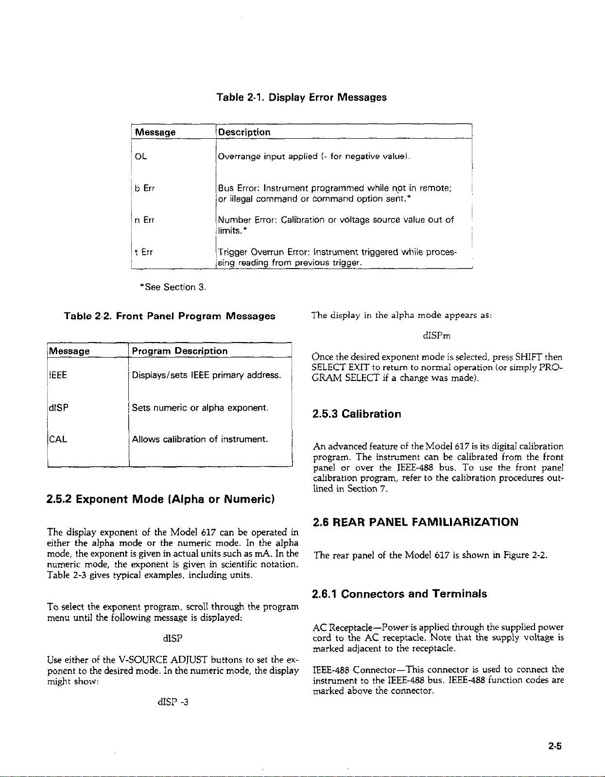
Table 2-1. Display Error Messages
Message
OL
b Err
Description
Overrange input applied (- for negative valueI.
Bus Error: Instrument programmed while npt in remote; ~
or illegal command or command option sent.*
n Err
(Number Error: Calibration or voltage source value out of
; limits.*
‘t Err
Trigger Overrun Error: Instrument triggered while processing reading from previous trigger.
“See Section 3.
Table 2-2. Front Panel Program Messages
Displays/sets IEEE primary address.
IdlSP
Sets numeric or alpha exponent.
I
I
The display in the alpha mode appears as:
dISI’m
Once the desired exponent mode is selected, press SHIFT then
SELECT EXIT to return to normal operation (or simply PRO-
GRAM SELECT if a change was made).
2.5.3 Calibration
CAL
Allows calibration of instrument.
2.5.2 Exponent Mode (Alpha or Numeric)
The display exponent of the Model 617 can be operated in
either the alpha mode or the numeric mode. In the alpha
mode, the exponent is given in actual units such as mA. In the
numeric mode, the exponent is given in scientific notation.
Table 2-3 gives typical examples. including units.
To select the exponent program, scroll through the program
menu until the following message is displayed:
dISI’
Use either of the V-SOURCE ADJUST buttons to set the ex-
ponent to the desired mode. In the numeric mode, the display
might show:
dISP -3
An advanced feature of the Model 617 is its digital calibration
program. The instrument can be calibrated from the front
panel or over the IEEE-488 bus. To use the front panel
calibration program, refer to the calibration procedures outiined in Section 7.
2.6 REAR PANEL FAMILIARIZATION
The rear panel of the Model 617 is shown in Figure 2-2.
2.6.1 Connectors and Terminals
AC Receptacle-Power is applied through the suppiied power
cord to the AC receptacle. Note that the supply voltage is
marked adjacent to the receptacle.
IEEE-488 Connector-This connector is used to connect the
instrument to the IEEE-488 bus. IEEE-488 function codes are
marked above the connector.
2-5
Page 25
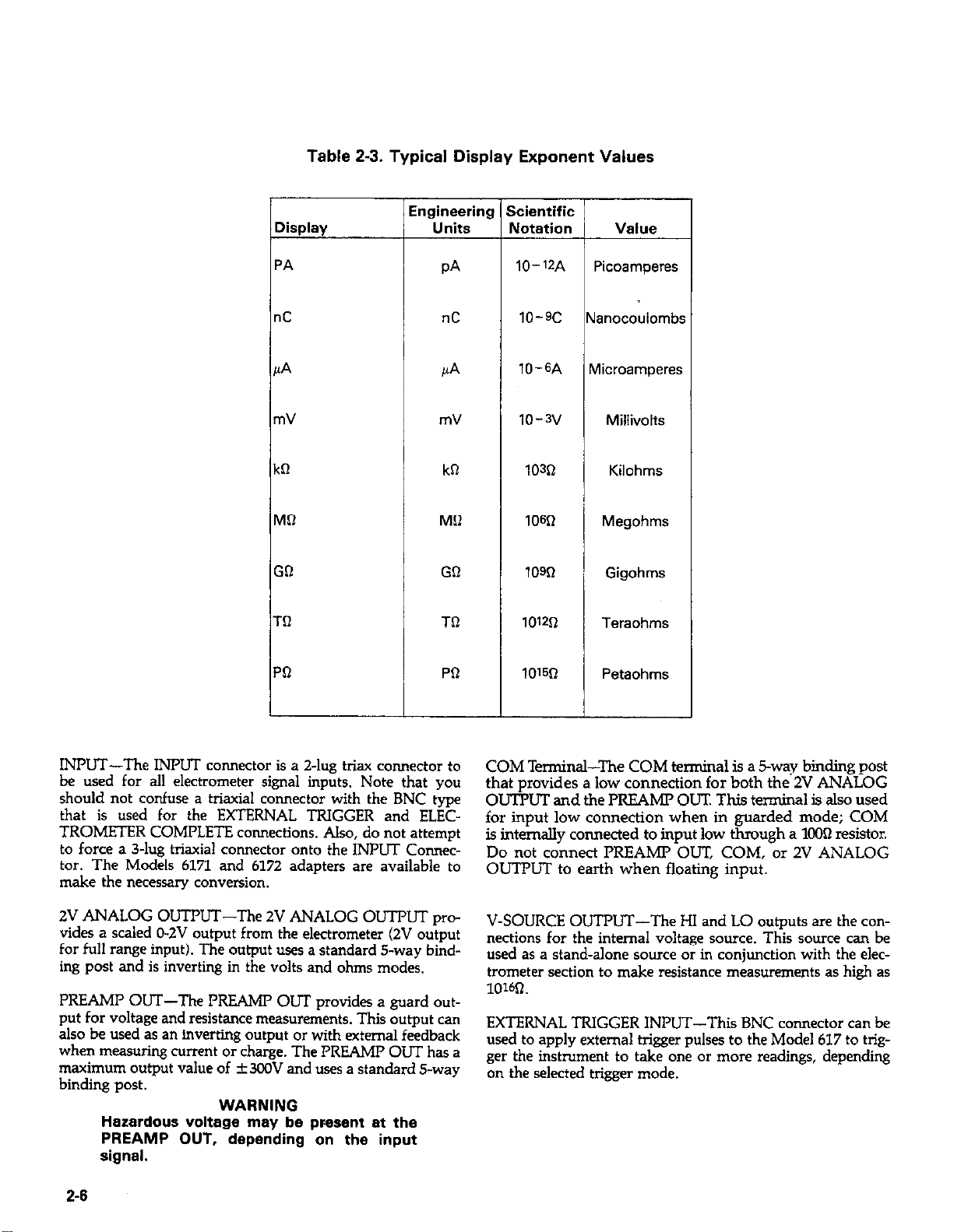
Table 2-3. Typical Display Exponent Values
I Display
IPA
nC
PA
mV
kR
MQ
GQ
Tfl
ingineering
Units
PA
!lC
PA
mV
kCI
MO
GR
TQ
icientific
Uotation
10-77-A
10-w
lo-GA
lo-3v
103Q
lO@l
low
1012sl
f
N,
anocoulombr
rv
licroamperes
Millivolts
Kilohms
1
Megohms
Gigohms
Teraohms
PQ
INPUT-The INPUT connector is a 2-lug triax connector to
be used for all electrometer signal inputs. Note that you
should not confuse a triaxial connector with the BNC type
that is used for the EXTERNAL TRIGGER and ELEC-
TROMETER COMPLETE connections. Also, do not attempt
to force a 3-lug triaxial connector onto the INPUT Connector. The Models 6171 and 6172 adapters are available to
make the necessary conversion.
2V ANALOG OUTPUT-The 2V ANALOG OUTPUT prc-
vides a scaled O-2V output from the electrometer (2V output
for full range input). The output uses a standard S-way bind-
ing post and is inverting in the volts and ohms modes.
PR!ZAMP OUT-The PREAMI’ OUT provides a guard cutput for voltage and resistance measurements. This output can
also be used as an inverting output or with external feedback
when measuring current or charge. The PREAMP OUT has a
maximum output value of k3C0V and uses a standard s-way
binding post.
WARNING
Hazardous voltage may be present at the
PREAMP OUT, depending on the input
signal.
PO
101522
COM Terminal-The COM terminal is a 5way binding post
that provides a low connection for both the 2V ANALOG
OIJ’IT’LT and the PREAMP OUT This terminal is also used
for input low connection when in guarded mode; COM
is internally connected to input low through a lC0Q resistor.
Do not connect PREAMP OUT, COM, or 2V ANALOG
OUTPUT to earth when floating input.
V-SOURCE OUTPUT-The HI and LO outputs are the connections for the internal voltage source. This source can be
used as a stand-alone source or in conjunction with the elec-
trometer section to make resistance measurements as high as
1owL
EXTERNAL TRIGGER INPUT-This BNC connector can be
used to apply external trigger pulses to the Model 617 to trigger the instrument to take one or more readings, depending
on the selected trigger mode.
Petaohms
i
2-6
Page 26
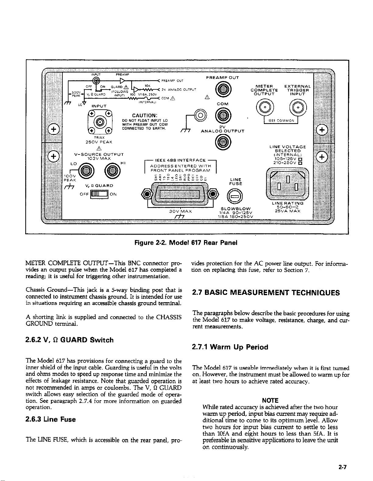
Figure 2-2. Model 617 Rear Panel
METER COMPLETE OUTPUT-This BNC connector prcvides an output pulse when the Model 617 has completed a
reading; it is useful for triggeling other instrumentation.
Chassis Ground-This jack is a s-way biding post that is
connected to instrument chassis ground. It is intended for use
in situations requiring an accessible chassis ground terminal.
A shorting link is supplied and connected to the CHASSIS
GROUND terminal.
2.6.2 V, !I GUARD Switch
The Model 617 has provisions for connecting a guard to the
inner shield of the input cable. Guarding is useful in the volts
and ohms modes to speed up response time and minimize the
effects of leakage resistance. Note that guarded operation is
not recommended in amps or coulombs. The V, Q GUARD
switch allows easy selection of the guarded mode of cperaticn. See paragraph 2.7.4 for more information on guarded
operation.
2.6.3 Line Fuse
The LINE FUSE, which is accessible on the rear panel, pro
vides protection for the AC power line output. For infcrmaticn on replacing this fuse, refer to Section 7.
2.7 BASIC MEASUREMENT TECHNIQUES
The paragraphs below describe the basic procedures for using
the Model 617 to make voltage, resistance, charge, and current measurements.
2.7.1 Warm Up Period
The Model 617 is usable immediately when it is first turned
on. However, the instrument must be allowed to warm up for
at least two hours to achieve rated accuracy.
NOTE
While rated accuracy is achieved after the two hour
wan-n up period, input bias current may require additional time to come to its optimum level. Allow
two hours for input bias current to settle to less
than 1OfA and eight hours to less than 5fA. It is
preferable in sensitive applications to leave the unit
on continuously.
2-7
Page 27
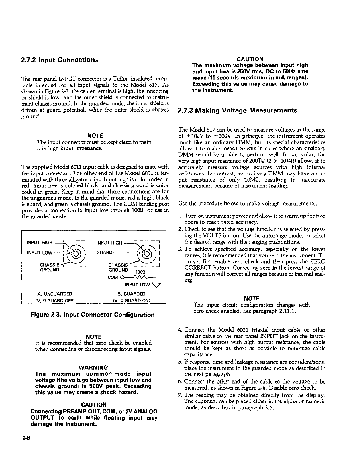
2.7.2 Input Connections
The rear panel IivPIJT connector is a Teflon-insulated receptacle intended for all input signals to the Model 617. As
shown in Figure 2-3, the center terminal is high, the inner ring
or shield is low, and the outer shield is connected to instrument chassis ground. In the guarded mode, the inner shield is
driven at guard potential, while the Outer shield is chassis
ground.
NOTE
The input connector must be kept clean to main-
tain high input impedance.
The supplied Model 6011 input cable is designed to mate with
the input connector. The other end of the Model 6011 is terminated with three alligator clips. Input high is color coded in
red, input low is colored black, and chassis ground is color
coded in green. Keep in mind that these connections are for
the unguarded mode. In the guarded mode, red is high, black
is guard, and green is chassis ground. The COM binding post
provides a connection to input low through loOn for use in
the guarded mode.
GROUND
GROUND
mm
CAUTION
The maximum voltage between input high
and input low is ZXlV rms. DC to 60Hz sine
wsve (10 seconds maximum in mA ranges).
Exceeding this value may cause damage to
the instrument.
2.7.3 Making Voltage Measurements
The Model 617 can be used to measure voltages in the range
of *lOpV to +2COV. In principle, the instrument operates
much like an ordinary DMM, but its special characteristics
allow it to make measurements in cases where an ordinary
DMM would be unable to perform well. In particular, the
very high input resistance of 2oOTSl (2 X 1OW) allows it to
accurately measure voltage sources with high internal
resistances. In contrast, an ordinary DMh4 may have an input resistance of only loMa. resulting in inaccurate
measurements because of instrument loading.
Use the procedure below to make voltage measurements.
1. Turn on instrument power and allow it to warm up for two
hours to reach rated accuracy.
2. Check to see that the voltage function is selected by pressing the VOLTS button. Use the autorange mode, or select
the desired range with the ranging pushbuttons.
3. To achieve specified accuracy, especially on the lower
ranges, it is recommended that you zero the instrument. To
do so, first enable zero check and then press the ZERO
CORRECT button. Correcting zero in the lowest range of
any function will correct all ranges because of internal scaling.
A. UNGUARDED 6. GUARDED
I”, ii GUARD OFF)
Figure 2-3. Input Connector Configuration
NOTE
W, R GUARD ON,
It is recommended that zero check be enabled
when connecting or disconnecting input signals.
WARNING
The maximum common-mode input
voltage (the voltage between input low and
chassis ground1 is 5OOV peak. Exceeding
this value may create a shock hazard.
CAUTION
Connecting PREAMP OUT, COM, or 2V ANALOG
C
XJTPUT to earth while floating input may
damage the instrument.
2-8
NOTE
The input circuit configuration changes with
zero check enabled. See paragraph 2.11.1.
4. Connect the Model 6011 triaxial input cable or other
similar cable to the rear panel INPUT jack on the instrument. For sources with high output resistance, the cable
should be kept as short as possible to minimize cable
capacitance.
5. If response time and leakage resistance are considerations,
place the instrument in the guarded mode as described in
the next paragraph.
6. Connect the other end of the cable to the voltage to be
measured, as shown in Figure 2-4. Disable zero check.
7. The reading may be obtained directly from the display.
The exponent can be placed either in the alpha or numeric
mode, as described in paragraph 2.5.
Page 28
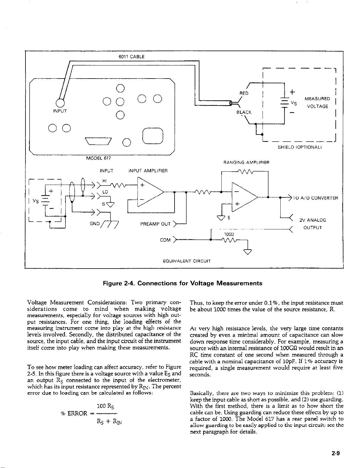
I+ I
vs= j
T- I
Figure 2-4. Connections for Voltage Measurements
TO A/D CONVERTER
>
Voltage Measurement Considerations: Two primary considerations come to mind when making voltage
measurements. especially for voltage sources with high output resistances. For one thing, the loading effects of the
measuring instrument come into play at the high resistance
levels involved. Secondly, the distributed capacitance of the
source, the input cable, and the input circuit of the instrument
itself come into play when making these measurements.
To see how meter loading can affect accuracy, refer to Figure
2-5. In this figure there is a voltage source with a value ES and
an output RS connected to the input of the electrometer,
which has its input resistance represented by RIN. The percent
error due to loading can be calculated as follows:
100 RS
% ERROR = -
Rs + RIN
Thus, to keep the error under 0.1%. the input resistance must
be about 1000 times the value of the source resistance. R.
At very high resistance levels, the very large time contants
created by even a minimal amount of capacitance can slow
down response time considerably. For example, measuring a
wurce with an internal resistance of 1OOGQ would result in an
RC time constant of one second when measured through a
cable with a nominal capacitance of 1OpF. If 1% accuracy is
required, a single measurement would require at least five
seconds.
Basically, there are two ways to minimize this problem: (1)
keep the input cable as short as possible, and (2) use guarding.
With the first method, there is a limit as to how short the
cable can be. Using guarding can reduce these effects by up to
a factor of 1000. The Model 617 has a rear panel switch to
allow guarding to be easily applied to the input circuit: see the
next paragraph for details.
2-9
Page 29
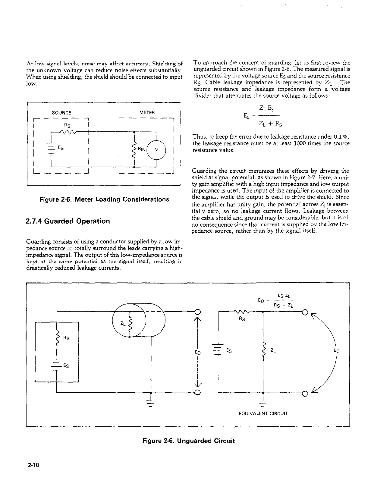
At low signal levels, noise may affect accuracy. Shielding of
the unknown voltage can reduce noise effects substantially.
When using shielding, the shield should be connected to input
IOW.
rI
/
To approach the concept of guarding, let us first review the
unguarded circuit shown in Figure 2-6. The measured signal is
represented by the voltage source ES and the source resistance
RS. Cable leakage impedance is represented by 2~ The
source resistance and leakage impedance form a voltage
divider that attenuates the source voltage as follows:
ZLES
E, =
ZL + Rs
Thus, to keep the error due to leakage resistance under O.l%,
the leakage resistance must be at least 1000 times the source
resistance value.
T ; / N”!
t-
---- J
G-lJ
L-----J
J
Figure 2-5. Meter Loading Considerations
2.7.4 Guarded Operation
Guarding consists of using a conductor supplied by a low impedance source to totally surround the leads carrying a highimpedance signal. The output of this low-impedance source is
kept at the same potential as the signal itself, resulting in
drastically reduced leakage currents.
Guarding the circuit miminizes these effects by driving the
shield at signal potential, as shown in Figure 2-7. Here, a uni-
ty gain amplifier with a high input impedance and low output
impedance is used. The input of the amplifier is connected to
the signal, while the output is used to drive the shield. Since
the amplifier has unity gain, the potential across ZLis essentially zero, so no leakage current flows. Leakage between
the cable shield and ground may be considerable, but it is of
no consequence since that current is supplied by the low impedance source, rather than by the signal itself.
2-10
Figure 2-6. Unguarded Circuit
Page 30
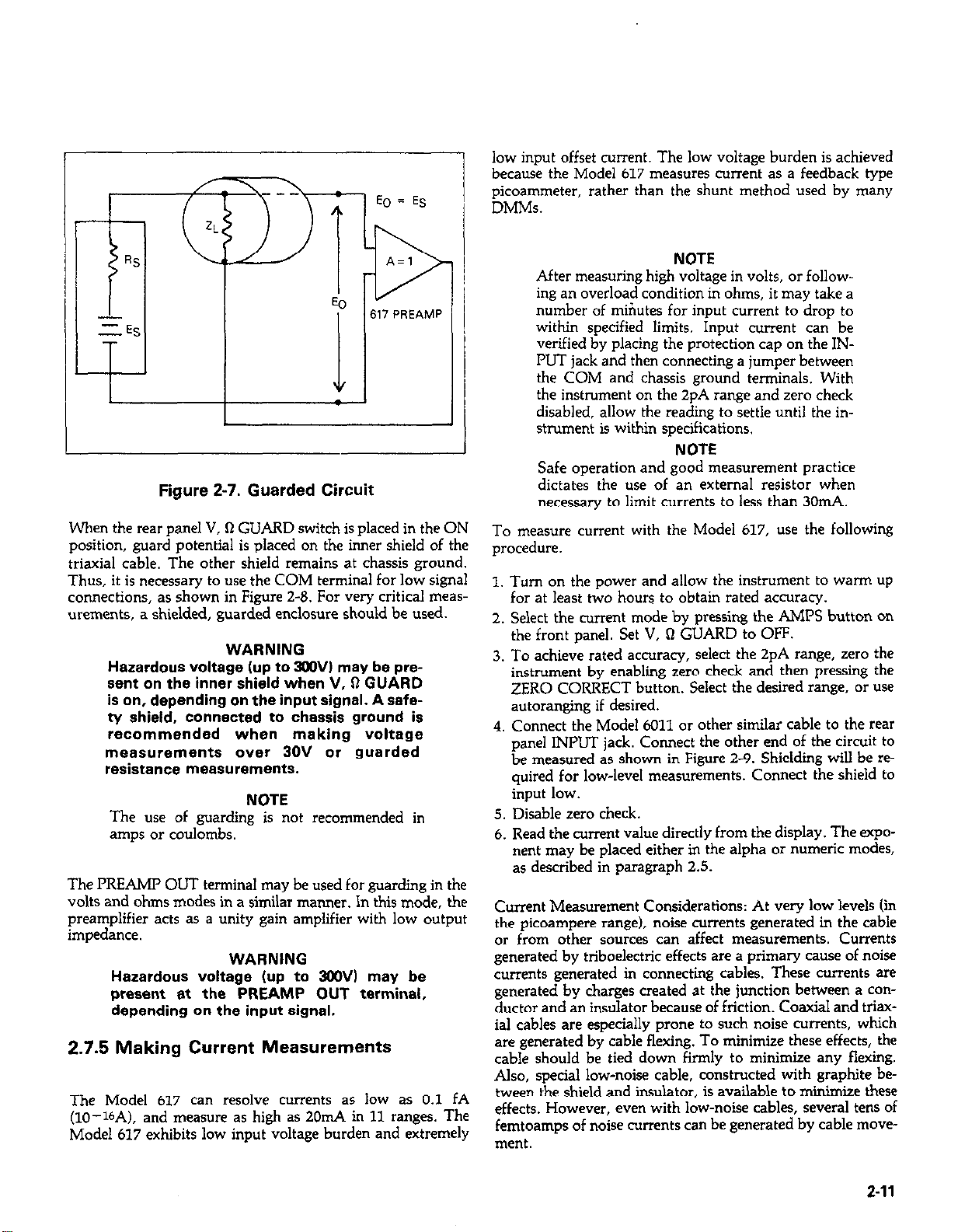
1
Figure 2-7. Guarded Circuit
-I
low input offset current. The low voltage burden is achieved
because the Model 617 measures current as a feedback type
picoammeter, rather than the shunt method used by many
DMMs.
NOTE
After measuring high voltage in volts, or following an overload condition in ohms, it may take a
number of miriutes for input current to drop to
within specified limits. Input current can be
verified by placing the protection cap on the INPUT jack and then connecting a jumper between
the COM and chassis ground terminals, With
the instrument on the 2pA range and zero check
disabled, allow the reading to settle until the instrument is within specifications.
NOTE
Safe operation and good measurement practice
dictates the use of an external resistor when
necessary to limit currents to less than 3011~4.
When the rear panel V, Q GUARD switch is placed in the ON
position, guard potential is placed on the inner shield of the
triaxial cable. The other shield remains at chassis ground.
Thus, it is necessary to use the COM terminal for low signal
connections, as shown in Figure 2-0. For very critical measurements, a shielded, guarded enclosure should be used.
WARNING
Hazardous voltage lup to 3OOV) may be present on the inner shield when V, Q GUARD
is on, depending on the input signal. A safety shield, connected to chassis ground is
recommended when making voltage
measurements over 30V or guarded
resistance measurements.
NOTE
The use of guarding is not recommended in
amps or coulombs.
The PREAMI’ OLJT terminal may be used for guarding in the
volts and ohms modes in a similar manner. In this mode, the
preamplifier acts as a unity gain amplifier with low output
impedance.
WARNING
Hazardous voltage (up to 3WV) may be
present at the PREAMP OUT terminal,
depending on the input signal.
2.7.5 Making Current Measurements
The Model 617 can resolve currents as low as 0.1 fA
(lo--lbA), and measure as high as 2011~4 in 11 ranges. The
Model 617 exhibits low input voltage burden and extremely
To measure current with the Model 617, use the following
procedure.
I. Turn on the power and allow the instrument to warm up
for at least two hours to obtain rated accuracy.
2. Select the current mode by pressing the AMPS button on
the front panel. Set V, Q GUARD to OFF.
3. To achieve rated accuracy, select the 2pA range, zero the
instrument by enabling zero check and then pressing the
ZERO CORRECT button. Select the desired range, or use
autoranging if desired.
4. Connect the Model 6011 or other similar cable to the rear
panel INPUT jack. Connect the other end of the circuit to
be measured as shown in Figure 2-9. Shielding will be required for low-level measurements. Connect the shield to
input low.
5. Disable zero check.
6. Read the current value directly from the display. The exponent may be placed either in the alpha or numeric modes,
as described in paragraph 2.5.
Current Measurement Considerations: At very low levels (in
the picoampere range), noise currents generated in the cable
or from other sources can affect measurements. Currents
generated by triboelectric effects are a primary cause of noise
currents generated in connecting cables. These currents are
generated by charges created at the junction between a conductor and an insulator because of friction. Coaxial and triaxial cables are especially prone to such noise currents, which
are generated by cable flexing. To minimize these effects, the
cable should be tied down firmly to minimize any flexing.
Also, special low-noise cable, constructed with graphite be-
tween the shield and insulator, is available to minimize these
effects. However, even with low-noise cables, several tens of
femtoamps of noise currents can be generated by cable move-
ment.
2-11
Page 31

Voltage burden is frequently a consideration when making
current measurements. Ideally, the input voltage burden
should be zero in order for the instrument to have absolutely
no effect on the circuit it is measuring. If the voltage burden is
too high, its effects can degrade measurement accuracy considerably.
Es
,=-
Rs
However, if EIN has a non-zero value, the current now
becomes:
To see how voltage burden can upset measurement accuracy,
refer to Figure Z-10. A source, represented by ES with an output resistance RS is shown connected to the input of a
picoammeter. The voltage burden is represented by a constant voltage source at the input as Em. If En\l were zero, the
current as seen by the meter would simply be:
00
cl
\
MODEL 617
/
Es -6~
IA
RS
Additional considerations include source resistance and
capacitance, as discussed in paragraph 2.14.
---_
SAFETY SHIELD
WARNING: USE SAFETY SHIELD FOR SIGNALS
ABOVE 30V h!OLTSl AND OHMS
2-12
v. R
GUARD
SWITCH
INPUT AMPLIFIER
PREAMP OUT
EQUIVALENT CIRCUIT (VOLTS MODE SHOWN)
Figure 2-8. Guarded Input Connections
RANGING AMPLIFIER
TO AiD
CONVERTER
Page 32
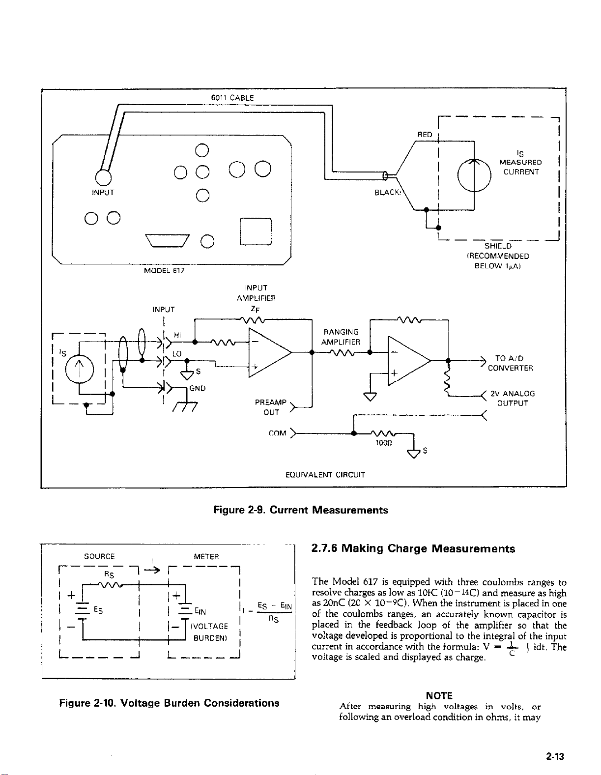
6011 CABLE
‘-jr-z-=
INPUT
00
DO
MODEL 617
INPVT
0
cl
INPIJT
AblPLIFIER
ZF
r------
------_
SHIELD
lRECOMMENOED
BELOW l&A,
TO AID
CONVERTER
Figure 2-9. Current Measurements
I/ = ES - EIN
L----- -1
Figure 2-10. Voltage Burden Considerations
I-----A
EQUIVALENT CIRCUT
2.7.6 Making Charge Measurements
The Model 617 is equipped with three coulombs ranges to
resolve charges as low as 1OfC (10-W) and measure as high
as 20nC (20 X 10-K). When the instrument is placed in one
of the coulombs ranges, an accurately known capacitor is
placed in the feedback loop of the amplifier so that the
voltage developed is proportional to the integral of the input
current in accordance with the formula: V = -$- j idt. The
voltage is scaled and displayed as charge.
I
NOTE
After measuring high voltages in volts, or
following an overload condition in ohms, it may
2-13
Page 33
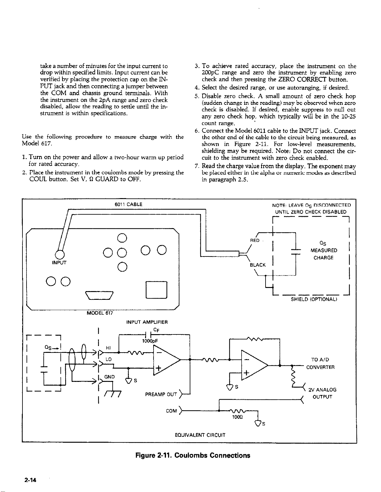
take a number of minutes for the input current to
drop within specified limits. Input current can be
verified by placing the protection cap on the INPUT jack and then connecting a jumper between
the COM and chassis ground terminals. With
the instrument on the 2pA range and zero check
disabled, allow the reading to settle until the instrument is within specifications.
Use the following procedure to measure charge with the
Model 617.
1. Turn on the power and allow a two-hour warm up period
for rated accuracy.
2. Place the instrument in the coulombs mode by pressing the
COUL button. Set V, R GUARD to OFF.
3. To achieve rated accuracy, place the instrument on the
2COpC range and zero the instrument by enabling zerc~
check and then pressing the ZERO CORRECT button.
4. Select the desired range, or use autoranging, if desired.
5. Disable zero check. A small amount of zero check hop
(sudden change in the reading) may be observed when zero
check is disabled. If desired, enable suppress to null out
any zero check hop, which typically will be in the lo-25
count range. ’
6. Connect the Model 6011 cable to the INPUT jack. Connect
the other end of the cable to the circuit being measured. as
shown in Figure 2-11. For low-level measurements,
shielding may be required. Note: Do not connect the circuit to the instrument with zero check enabled.
7. Read the charge value from the display. The exponent may
be placed either in the alpha or numeric modes as described
in paragraph 2.5.
6011 CABLE
0 \ RED
A
IN;;;T
00
0
00
MODEL 617
00
cl ---- 1
INPUT AMPLlFlER
NOTE: LEAVE OS DISCONNECTED
“NTlL ZERO CHECK DISABLED
r----i
QS
MEASURED
CHARGE
SHIELD ,OPTIONAL)
J
TO A/D
CONVERTER
2-14
PREAMP OUT
EQUIVALENT C,RCUIT
Figure 2-11. Coulombs Connections
Page 34
Note that the coulombs function can also be used to measure
current. The advantage of doing so is that noise in the
measurement is substantially reduced because of the integrating procw. To measure current using the coulombs
function, proceed as follows:
discussed in paragraph 2.8, uses the built in voltage source.
With the constant current method discussed here, the instrument can resolve resistances as low as O.la and measure as
high as 2COGR.
1. Place the instrument in the coulombs function and select
the desired range, or use autoranging, if desired.
2. Enable zero check and connect the current to be measured
to the INPUT jack (see Figure Z-9).
3. Disable zero check and note the charge measurement at the
end of a specific interval of time (for example, 10 seconds).
4. To determine the current, simply divide the measured
charge by the time in seconds. For example, if a charge of
l2nC is seen after a lo-second interval, the current is
121010 = 1.2nA. (Using Data Store at a 10 second rate
can ease data taking).
5. As an alternative Lo the above procedure, connect a chart
recorder to the 2V ANALOG OUTPUT (paragraph 2.9)
and graph the measured charge. Since the current is given
by I=dQ/dt, the current at any point is equal to the slope
of the graph at that point, after applying the appropriate
scaling factor (loOpC/V, 2CGpC range; l&/V, 2nC range;
lonC/V, 2Onc range).
CAUTION CAUTION
Connecting PREAMP OUT, COM, or 2V ANALOG Connecting PREAMP OUT, COM, or 2V ANALOG
OUTPUT to earth while floating input may OUTPUT to earth while floating input may
damage the instrument. damage the instrument.
Charge Measurement Considerations: A primary consideration when making charge measurements is the input offset
current of the integrating amplifier. Any such current is integrated along with the input signal and reflected in the final
reading. The Model 617 has a maximum input offset current
of 5 x lo-ISA at 23°C. This value double every 10°C. This
input offset current translates into a charge of 5 X lo-15C
per second at a temperature of 23OC. This value must be subtracted from the fiil reading to obtain the correct value.
When using an external voltage source, the input current
should be limited to less than 1mA by placing a resistor in
series with the high input lead. The value of this resistor
should be at least: R=lOOOV (in ohms) where V is the
voltage across the capacitor, or the compliance of the current being integrated.
2.7.7 Resistance Measurements
To measure resistance with the Model 617, use the following
procedure:
1. Turn on the power and allow a two-hour warm-up period
for rated accuracy.
2. Press the OHMS button to place the instrument in the COTrect mode.
3. For maximum accuracv, place the instrument on the 2k0
range and zero the ins&&ent by enabling zero check and
then pressing the ZERO CORRECT button.
4
Select the desired range, or use autoranging, if desired.
5
Connect the Model 6011 or similar cable to the INPUT
jack. Keep the cable as short as possible to minimize the effects of cable capacitance. Connect the other end of the
cable to the resistance to be measured, as shown in Figure
2-12. For measurements above lGn, it is recommended
that you use guarded connections, as described in
paragraph 2.7.4.
6. Disable zero check.
7. Take the reading from the display. The exponent may be
placed in either the alpha or numeric modes, as described
in paragraph 2.5.
Resistance Measurement Considerations: When measuring
high resistance values, there are two primary factors that can
affect measurement accuracy and speed. Any leakage r&stance in the connecting cable or test fixture can decrease the
actual resistance seen by the instrument. Also, capacitance of
the cable or input circuit can slow down the response time
considerably.
These two problems can be minimized by using guarding,
especially when measuring r&stances above lG% Guarding
is further discussed in paragraph 2.7.4. Noise pickup can also
be a problem, in which case the resistor must be shielded.
Connecl the shield to input low.
At low resistances, lead resistance can be a consideration.
Cancel the effects of lead resistance by shorting the input
leads and enabling suppress with zero check disabled. Leave
suppress enabled for subsequent measurements.
The Model 617 can make resistance measurements using two
different methods: the constant current method and the constant voltage method. The constant voltage method, which is
2-15
Page 35
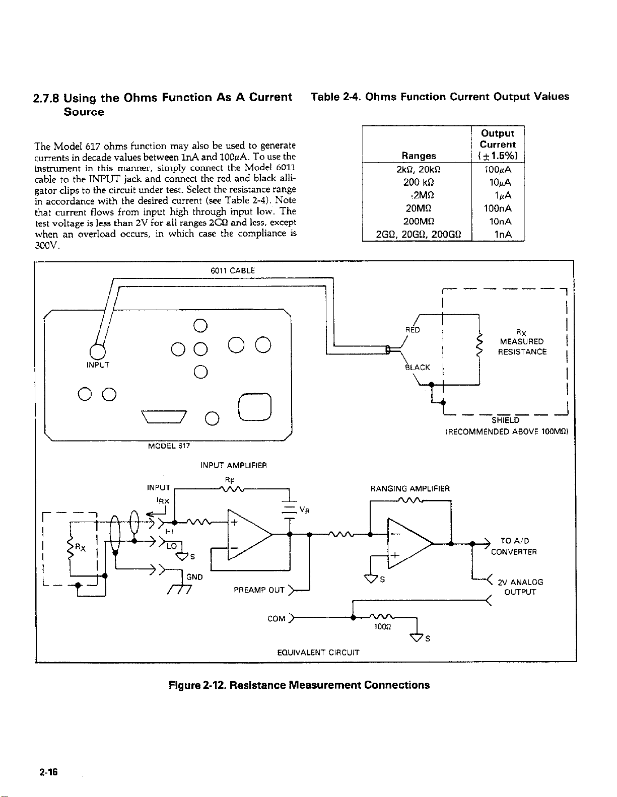
2.7.8 Using the Ohms Function As A Current
MEASURED
------
_1
Source
The Model 617 ohms function may also be used to generate
currents in decade values between InA and lOOpA. To use the
instrument in this manner, simply connect the Model 6011
cable to the INPUT jack and connect the red and black alligator clips to the circuit under test. Select the resistance range
in accordance with the desired current (see Table 2-4). Note
that current flows from input high through input low. The
test voltage is less than 2V for all ranges 2GQ and less. except
when an overload occurs, in which case the compliance is
3OQv.
Table 2-4. Ohms Function Current Output Values
Id/
l-
oo
,
6011 CABLE
-0
MDDEL 617
INPUT AMPLIFIER
0
\
/
I
I
L
-
-----
I-
\ :
^. ^.. I
,RECOMMENDED ASDVE 100M~l
RESISTANCE
SHIELD
1
1
I
2-16
COM >
EDUIVALENT CIRCUIT
Figure 2-12. Resistance Measurement Connections
1
s
Page 36
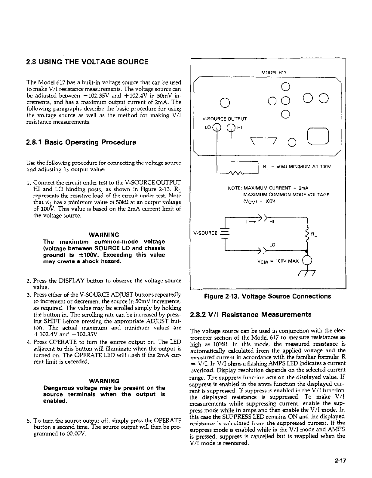
2.8 USING THE VOLTAGE SOURCE
00
The Model 617 has a built-in voltage source that can be used
to make V/I resistance measurements. The voltage source can
be adjusted between -102.35V and +102.4V in 50mV increments, and has a maximum output current of 2mA. The
following paragraphs describe the basic procedure for using
the voltage source as well as the method for making V/I
resistance measurements.
2.8.1 Basic Operating Procedure
Use the following procedure for connecting the voltage swrce
and adjusting its output value:
1. Connect the circuit under test to the V-SOURCE OUTPUT
HI and LO binding posts, as shown in Figure Z-13. RL
represents the resistive load of the circuit under test. Note
that RL has a minimum value of 5OkSl at an output voltage
of 1COV. This value is based on the 2mA current limit of
the voltage source.
WARNING
The maximum common-mode voltage
(voltage between SOURCE LO and chassis
ground) is +lOOV. Exceeding this value
may create a shock hazard.
I
I
V-SOURCE D”TP”T
LO
PP
\ I
MODEL617
n
0:
0
HI
-0
RL = 50kR MlNlM”M AT loo”
NOTE: MAXlMLlM CURRENT = ZrnA
MAXIMUM COMMON MODE VOLTAGE
(“CM) = 1oov
\
0
/
2. Press the DISPLAY button to observe the voltage source
V&e.
3. Press either of the V-SOURCE ADJUST buttons repeatedly
to increment or decrement the source in 5ChnV increments,
as required. The value may be scrolled simply by holding
the button in. The scrolling rate can be increased by press-
ing SHIFT before pressing the appropriate ADJUST but-
ton. The actual maximum and minimum values are
+102.4V and -102.35V.
4. Press OPERATE to turn the source output on. The LED
adjacent to this button will illuminate when the output is
turned on. The OPERATE LED will flash if the 2nd cur-
rent limit is exceeded.
WARNING
Dangerous voltage may be present on the
sourca terminals when the output is
enabled.
5. To turn the source output off, simply press the OPERATE
button a second time. The source output will then be programmed to OO.OLW.
Figure 2-13. Voltage Source Connections
2.8.2 V/I Resistance Measurements
The voltage source can be used in conjunction with the electrometer section of the Model 617 to measure resistances as
high as lOWI. In this mode, the measured resistance is
automatically calculated from the applied voltage and the
measured current in accordance with the familiar formula: R
= V/I. In V/I ohms a flashing AMPS LED indicates a current
overload. Display resolution depends on the selected current
range. The suppress function acts on the displayed value. If
suppress is enabled in the amps function the displayed cur-
rent is suppressed. If suppress is enabled in the V/I function
the displayed resistance is suppressed. To make V/I
measurements while suppressing current, enable the suppress mode while in amps and then enable the V/I mode. In
this case the SUPPRESS LED remains ON and the displayed
resistance is calculated from the suppressed current. If the
suppress mode is enabled while in the V/I mode and AMPS
is pressed, suppress is cancelled but is reapplied when the
V/I mode is reentered.
2-17
Page 37
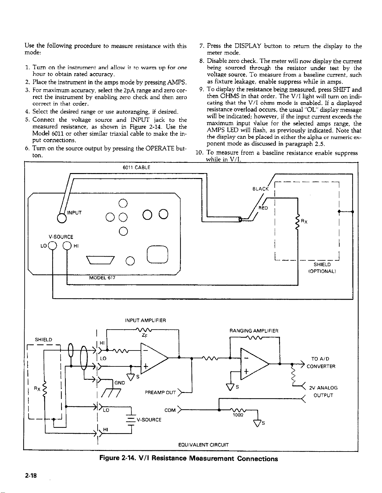
Use the following procedure to measure resistance with this
mode:
1. Turn on the instrument and allow it to warm up for one
hour to obtain rated accuracy.
2. Place the instrument in the amps mode by pressing AMPS.
3. For maximum accuracy, select the 2pA range and zero COT-
rect the instrument by enabling zero check and then zero
correct in that order.
4. Select the desired range or use autoranging, if desired.
5. Connect the voltage source and INPUT jack to the
measured resistance, as shown in Figure 2-14. Use the
Model 6011 or other similar triaxial cable to make the input connections.
6. Turn on the source output by pressing the OPERATE button.
7. Press the DISPLAY button to return the display to the
meter mode.
8. Disable zero check. The meter will now display the current
being sourced through the resistor under test by the
voltage sowce. To measure from a baseline current, such
as fixture leakage, enable suppress while in amps.
9. To display the resistance being measured, press SHIFT and
then OHMS in that order. The V/I light will turn on indicating that the V/I ohms mode is enabled. If a displayed
resistance overload occurs, the usual “OL” display message
will be indicated; however, if the input current exceeds the
maximum input G&e for the selected amps range, the
AMPS LED will flash, as previously indicated. Note that
the display can be placed in either the alpha or numeric exponent mode as discussed in paragraph 2.5.
10. To measure from a baseline resistance enable suppress
while in V/T
V-SOURCE
LO HI
0
-0 0
MODEL 617
/
I
L-- -SELDl
IOPTlONALl
I
rgure z-14. v/I Hesistance Measurement Connections
Page 38
V/I Resistance Measurement Considerations: The main advantage of using the constant voltage method for resistance
measurements is that the effects of leakage resistance and
distributed capacitance are minimized. Because of these factors, the resistance range of the instrument can be greatly increased, in the case of the Model 617, to 1016fl. However,
there are certain characteristics pertaining to high resistance
measurements that require discussion.
Such variation in resistance is known as rhe voltage coefficient. The Model 617 can be used to characterize such
resistance changes by measuring the resistance with a number
of different applied voltages. Once the variations are known,
the voltage coefficient of the resistor being tested can be
calculated. The method for determining the voltage coeffi-
cient of these resistors is discussed in Section 4.
A primary consideration when using this mode is to match
the voltage and current ranges to optimize accuracy. In most
cases, it is best use the maximum voltage value possible (except as indicated below) and set the current range accordingly. As with other Model 617 measurements, the instrument
should be placed on the most sensitive range possible without
overranging the electrometer section. Doing so will optimize
the measurement for resolution and accuracy. Autoranging
can facilitate range selection.
At very high resistance values, the corresponding current, as
seen by the instrument, will be extremely low. Thus, any current generated by the triaxial input cable will be reflected in
the final measurement. To minimize such problems, use lownoise graphite hiaxial cable. (such as the Model 6011). Tie
down the cable to avoid any triboelectric currents that might
be generated by cabling flexing. In many situations, shielding
of the circuit under test will also be required to minimize noise
pickup.
Although V/I resistance measurements are much lms suscep-
tible to the effects of leakage resistance than resistance
measurements made with the constant current method, there
are sane cases where leakage resistance could affect V/I
resistance measurements. For example, test fixture leakage
paths may appear in parallel with the device beiig measured,
introducing errors in the measurement. As with other Model
617 high impedance measurements, these errors can be
minimized by using proper insulating material (such as
Teflon) in fixture terminal connections.
2.9 ANALOG OUTPUTS
The Model 617 has two analog outputs on the rear panel. The
2V ANALOG OUTPUT provides a scaled O-2V output with a
value of 2V corresponding to full range input. The PREAMP
OUT is especially useful in situations requiring buffering.
These two analog outputs are discussed the the following
paragraphs.
WARNING
When floating Input Low above 30V from
earth ground. hazardous voltage will be
present at the analog outputs. Hazardous
voltage may also be present when msasuring in ohms, or when the input voltage exceeds 30V in the volts mode.
CAUTION
Connecting PREAMP OUT, COM, or 2V ANALOG
OUTPUT to earth while floating input may
damage the instrument.
2.9.1 2V Analog Output
The 2V ANALOG OUTPUT provides a scaled Q2V output
that is inverting in the volts and ohms modes. Connections
for using this output are shown in Figure 2-15. For a full range
input, the output will be 2V; typical examples are listed in
Table 2-5. The 2V ANALOG OUTPUT is not corrected dur-
ing calibration. Gain errors of up to 3% may appear at this
output, depending on function and range selection.
Any leakage current through cables and test fixtures can be
minimized if care is taken. To cancel these effects, set up the
measurement exactly as desired, but leave the resistor under
test disconnected. Program the voltage source to the desired
value and turn on its output. With the instrument in the amps
mode, enable suppress to null the leakage current. Turn off
the source, connect the resistor, and re-enable the voltage
source. Place the instrument in the V/I ohms mode and proceed with the measurement.
High megohm resistors are somewhat curious devices, often
exhibiting characteristics somewhere between those of an in-
sulator and a normal re&tor. Because of these unique traits,
the measured value of such a resistor will often vary with ap
plied voltage.
Note that the output impedance is IOk% to minimize the ef-
fects of loading, the input impedance of the device connected
to the 2V ANALOG OUTPUT should be as high as possible.
For example, with a device with an input impedance of
lOM0, the error due to loading will be approximately 0.1%
2.9.2 Preamp Out
The PREAMP OUT of the Model 617 follows the signal
amplitude applied to the INPUT terminal. Some possible uses
for thepreamp output include buffering of the input signal, as
2-19
Page 39
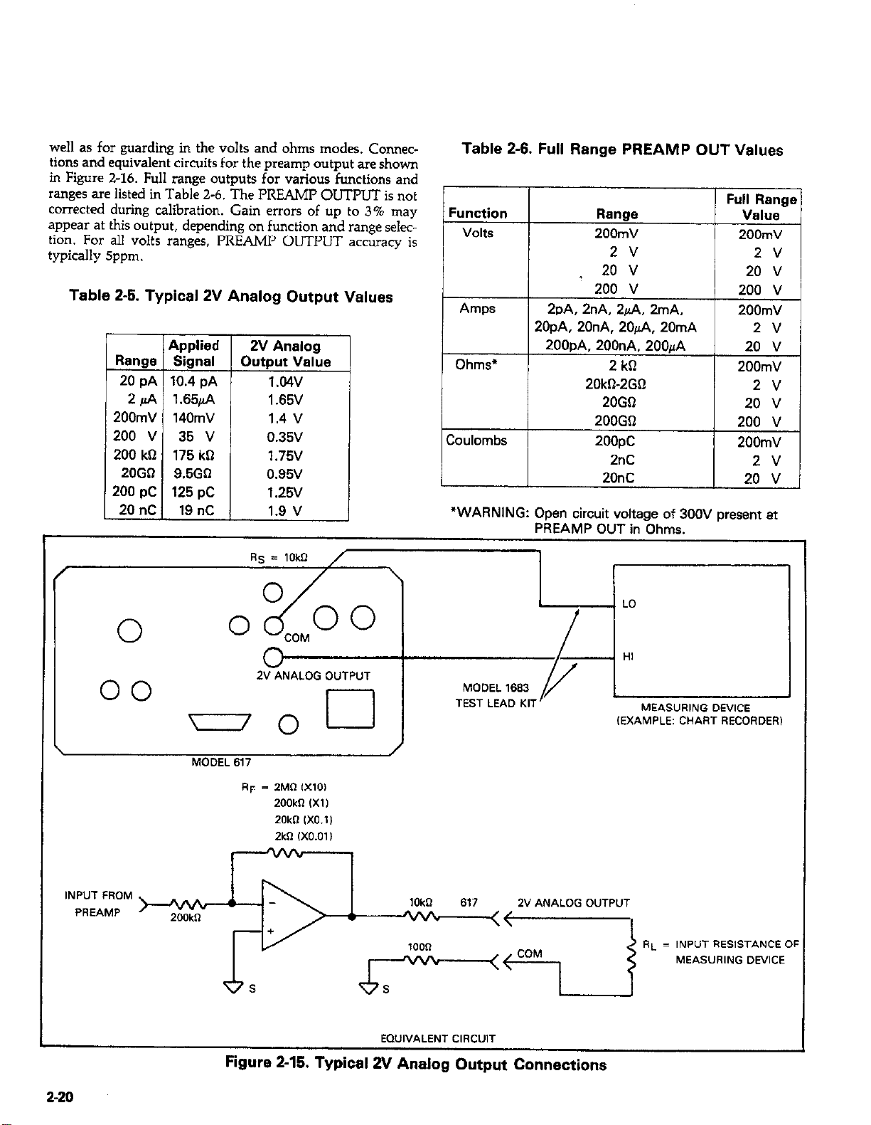
well as for guarding in the volts and ohms modes. Connec-
tions and equivalent circuits for the preamp output are shown
in Figure 2-16. Full range outputs for various functions and
ranges are listed in Table 2-6. The PREAMP OUTPUT is not
corrected during calibration. Gain errors of up to 3% may
appear at this output, depending on function and range selection. For all volts ranges, PREAMP OUTPUT accuracy is
typically Sppm.
Table 2-5. Typical 2V Analog Output Values
ZV Analog
Output Value
1.04v
1.65V
1.4 v
0.35v
1.75v
0.95v
1.25V
1.9 v
Table 2-6. Full Range PREAMP OUT Values
_-.--
I
Amps
Ohms*
Coulombs 1
200mV
2 v
,
20 v
200 v
2~4 2nA, 2/ln, 2mA.
20pA. 20nA. 20& 20mA
200pA, 200nA. 2OOfi
2 k0
20kD-2GQ
20GQ
200GQ
2OODC
200mV
2v
20 v
200 v
200mV
2v
20 v
200mV
2v
20 v
1 200 v
I 200mV
I 2v I
“WARNING: Open circuit voltage of 300V present at
PREAMP OUT in Ohms.
\
INPUT FROM
PREAMP
2-20
00
n/o
MODEL 617
200kR
,j-xiiL
cl
RF = 2MR IX101
200kR ,X1)
20kR 1X0.11
2kR lXO.01 I
EQUIVALENT CIRCUIT
Figure 2-15. Typical 2V Analog Output Connections
-----I
(EXAMPLE: CHART RECORDER1
Page 40
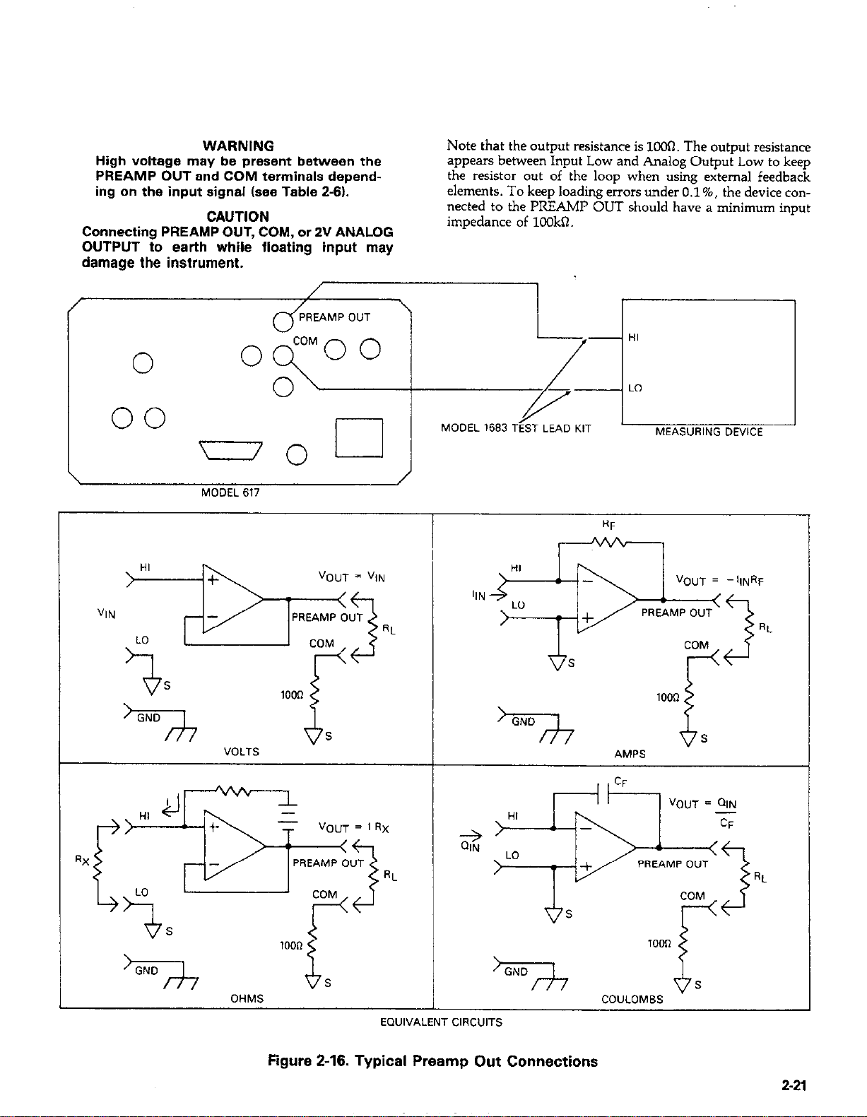
WARNING
High voltage may be present between the
PREAMP OUT and COM terminals depending on the input signal (see Table 2-6).
CAUTION
Connecting PREAMP OUT, COM, or 2V ANALOG
OUTPUT to earth while floatina inout mav
damage the instrument.
0
0
- ’
Note that the output resistance is 10oR. The output resistance
appears between Input Low and Analog Output Low to keep
the resistor out of the loop when using external feedback
elements. To keep loading errors under 0.1%. the device connetted to the PREAMP OUT should have a minimum input
impedance of 1OOkQ.
Jf------
00
77
GND
MODEL 617
VOLTS
lOoR
MODEL 1683 TEST LEAD KIT
S
MEASURING DEVICE
>r--
EWIVALENT CIRCUITS
figure 2-16. Typical Preamp Out Connections
1000
COULOMBS
a
Rt
t
6
1
2-21
Page 41
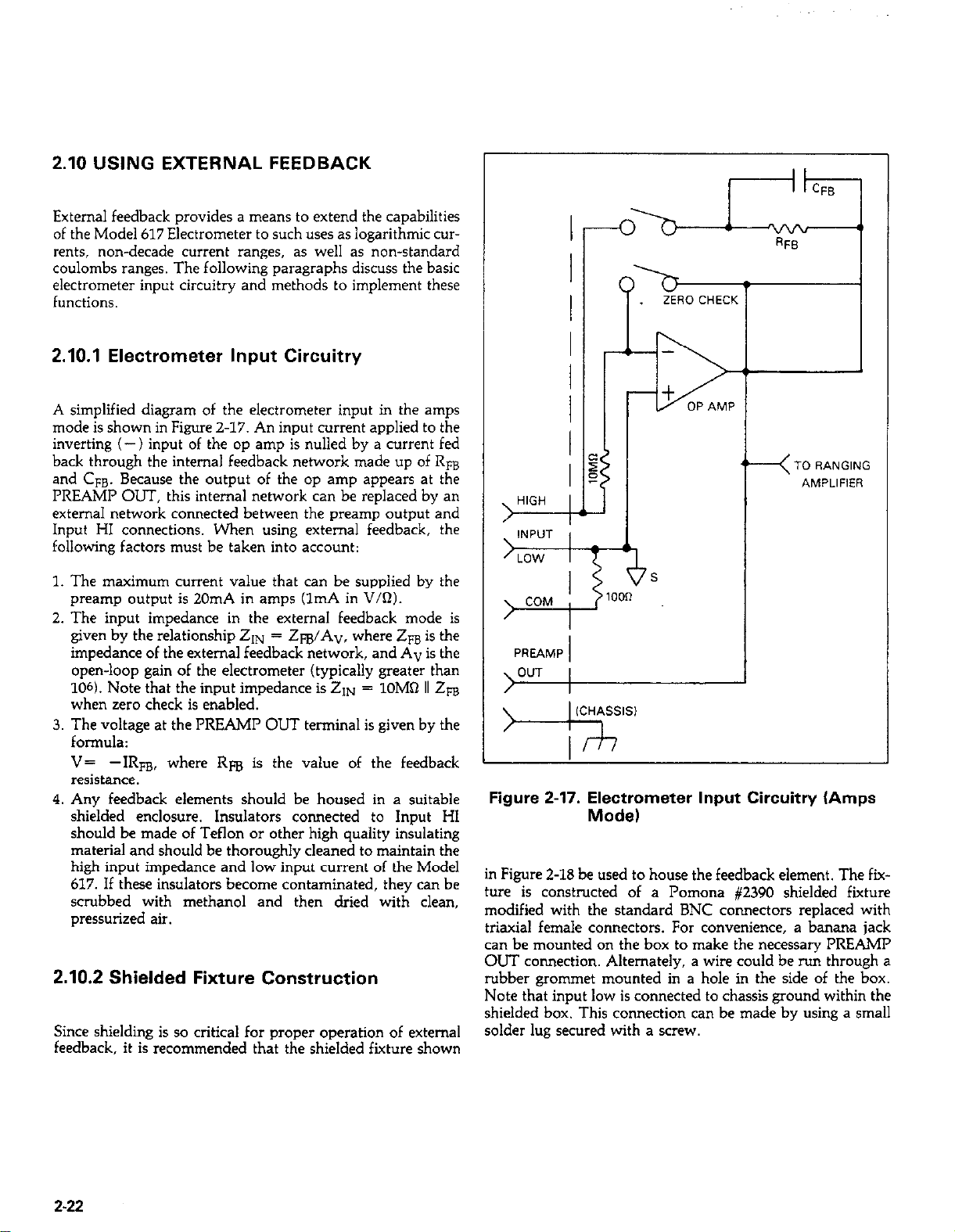
2.10 USING EXTERNAL FEEDBACK
External feedback provides a means to extend the capabilities
of the Model 617 Electrometer to such uses as logarithmic cur-
rents, non-decade current ranges, as well as non-standard
coulombs ranges. The following paragraphs discuss the basic
electrometer input circuitry and methods to implement these
functions.
2.10.1 Electrometer Input Circuitry
A simplified diagram of the electrometer input in the amps
mode is shown in Figure 2-17. An input current applied to the
inverting (-) input of the op amp is nulled by a current fed
back through the internal feedback network made up of Rm
and CFB. Because the output of the op amp appears at the
PREAMP OUT, this internal network can be replaced by an
external network connected between the preamp output and
Input HI connections. When using external feedback, the
following factors must be taken into account:
1. The maximum current value that can be suppiied by the
preamp output is 20mA in amps (1mA in V/R).
2. The input impedance in the external feedback mode is
given by the relationship 21~ = Z@A”, where Zm is the
impedance of the external feedback network, and A” is the
open-loop gain of the electrometer (typically greater than
106). Note that the input impedance is ZIN = lOM0 II 2~
when zero check is enabled.
3. The voltage at the PREAMI’ OUT terrrtinal is given by the
formula:
V= -IRFB, where Rm is the value of the feedback
resistance.
4. Any feedback elements should be housed in a suitable
shielded enclosure. Insulators connected to Input HI
should be made of Teflon or other high quality insulating
material and should be thoroughly cleaned to maintain the
high input impedance and low input current of the Model
617. If these insulators become contaminated, they can be
scrubbed with methanol and then dried with clean,
pressurized air.
2.10.2 Shielded Fixture Construction
Since shielding is so critical for proper operation of external
feedback, it is recommended that the shielded fixture shown
Figure 2-17. Electrometer Input Circuitry (Amps
Mode)
in Figure 2-18 be used to house the feedback element. The fixture is constructed of a Pomona #2390 shielded fixture
modified with the standard BNC connectors replaced with
triaxial female connectors. For convenience, a banana jack
can be mounted on the box to make the necessary PREAMP
OUT connection. Alternately, a wire could be ru11 through a
rubber grommet mounted in a hole in the side of the box.
Note that input low is connected to chassis ground within the
shielded box. This connection can be made by using a small
solder lug secured with a screw.
2-22
Page 42

4. CONSTRUCTION
FEEDBACK
1
I
A A
HI
IlV I-
LO
I
GND) -
--v--J PoMoNAsoX -
IT:, OESCRlPTlON MFR. PART NUMBER
SHIELDED FIXTURE POMONA “2390
2 FEMALE TRIAXIAL KEITHLEY CS-181
3 SANANPl JACK WTHLEY W-9-2
4 TRlAXlAL CABLE KElTHLEY 6011
5 TRIAXIAL CABLE KEITHLEY ,024
-- ---
PARTS LIST
I
I
I
I
Figure 2-18. Shielded Fixture Construction
1,
’ ’ PREAMP OVT
HI
/I
\ LO
/I
GND
TO RANGING
AMP AND AID
s
617 lNP”T AMP
2.10.3 External Feedback Procedure
Use the following procedure to operate the Model 617 in the
external feedback mode.
1. Connect the feedback element between the PREAMP OUT 1. Connect the feedback element between th
terminal and the Input High terminal. terminal and the Input v4-h +--in=’
2. Place the instrument in LX CXKJXWZ~ x 2. Place the instrument in the external feedback mode by
pressing the SHIFT then VOLTS buttons pressing the SHIFT then VOLTS buttons in that order. The
AMPS and VOLTS indicators will i AMPS and VOLTS indicators will illuminate simul-
taneously in the external feedback mode taneously in the external feedback mode.
3. The display will show the voltage measured at the output
of the input preamplifier (PREAMP OUT). However, the
“V exponent will not appear as in the volts mode. For example, with a 150mV output the display will show:
150.00 m
4. External feedback may be temporarily digitally calibrated
as outlined in paragraph 7.4.16.
5. The external feedback mode may be cancelled by pressing
one of the four functions keys (VOLTS, OHMS, COUL, or
AMPS), or by pressing SHIFT OHMS to enter V/I OHMS.
2-23 2-23
Page 43

2.10.4 Non-standard Coulombs Ranges
In its standard form, the Model 617 has three coulombs
ranges allowing it to measure charge between 1OfC and 20nC.
Different charge measurement ranges can be used by placing
an external feedback capacitor between the PREAMP OUT
and Inout HI and then olacing the instrument in the external
feedback mode. . -
Charge is related to capacitance and voltage by the formula:
Q = CV, where Q is the charge, C is the capacitance, and V
is the voltage. The Model 617 display will read charge directly
in units determined by the value of C. For example, a IFF
capacitor will result in a displayed reading of lpC/V. shield the device.
A solution to these constraints is to use a transistor configured as a “transdiode” in the feedback path, as shown in
Figure Z-19. Analyzing the transistor in this configuration
leads to the relationship:
V = kT/q[lnI/I o- In(h&(l + h&)1
where hE is the current gain of the transistor.
From this equation, proper selection of Q1 would require a
device with high current gain (h&,which is maintained over
a wide range of emitter currents. Suitable devices for this application include Analog Devices AD812 and Precision
Monolithics MAT-01. Use the enclosure in Figure 2-18 to
In practice, the feedback capacitor should be greater than
1COpF for feedback stability and of suitable dielectric material
to ensure low leakage and low dielectric absorption.
Polystyrene, polypropylene and Teflon dielectric capacitors
are examples of capacitor types with these desirable
characteristics. The capacitor should be mounted in a shielded fixture like the one in Figure Z-18.
To discharge the external feedback capacitor, enable zero
check. The discharge time constant will be given by: T =
(lOM0) (Cm).
2.10.5 Logarithmic Currents
The use of a diode junction in the external feedback path permits a logarithmic current-to-voltage conversion. This
relationship for a junction diode is given by the equation:
V = mkT/q h-@/I,) + IRB
where q = unit charge (1.6022X10⁻¹⁹). k = Boltzmann’s
constant (1.3806X10-U). and T = temperature (OK).
The limitations in this equation center on the factors I,, m
and RB, I, is the extrapolated current for V,. An empirical
proportional constant, m, accounts for the different character
current conduction (recombination and diffusion
mechanisms) within the junction, typically varying between 1 and 2. Finally, R, constitutes the ohmic bulk resistance of the diode junction material. I0 and R, limit the
usefulness of the junction diode at low and high currents,
respectively. The factor m introduces non-linearities between those two extremes. Because of these limitations,
most diodes have a limited range of logarithmic behavior.
Frequency compensation/stabilization is accomplished by adding a feedback capacitor, Cm. The value of this capacitor
depends on the particular transistor being used and the maxi-
mum current level expected. Compensation at maximum current is required because the dynamic impedance will be
minimum at this point. It should be noted that the response
speed at lower currents will be compromised due to the increasing dynamic impedance, which is given by the following
formula:
dV
2 =-= KT/qI = 0.026/I (@ 25°C)
d1
Using the above transistors, a minimum RC time constant of
lC@sec at maximum input current would be used. At 11~
(m&) of lOOpA, this v&e would correspond to 0.4~F. No&
that at loOnA this value would increase the RC resoonse time
constant to 100msec. A minimum capacitance of 1OOpF is
recommended.
Although the input signal to this particular circuit is assumed
to be a current, conversion to voltage input could be performed by placing a shunt resistor across the input. However,
the nominal voltage burden of 1mV must be considered as an
error signal that must be taken into account.
Further processing of the current response can be achieved by
using suppress. For example, suppress could be enabled with
a reference input current applied. For all subsequent currents,
the natural logarithm of the ratio of the measured current to
the suppressed current would then be displayed:
2-24
Page 44

VDISP = VRVU) - VSUPPRESS kT/q (I* IREAD&
- In kUPPRESS&)
= kT/q(ln(
= 0.026/1(‘“( IREAD
IREAD
h’PRESS
h’PRESS
)I
)I @ 25°C
2.10.5 Non-Decade Current Gains
The Model 617 electrometer input uses internal decade
resistance feedback networks for the current ranges. In some
applications, non-decade current gains may be desirable. As
shown in Figure 2-20, an external feedback resistor. R,,, can
be used to serve this purpose. Limitations on the magnitude
of the feedback curr,ent require that the value of RFB be
greater than loan.
NOTE
The circuit topology of Figure 2-19 works for
positive input currents only. For bipolar input
signals, an external offset bias must be applied or
use a PNP at QL.
:“RRENT
\ . .
IOMR
Note that external feedback can be temporarily calibrated
i12% using the calibration program with the calibration
jumper in the disable position. See Section 7.
I r? I
TO RANGING
NOTE: PRESS SHIFT VOLTS TO ENTER
EXTERNAL FEEDBACK MODE
Figure 2-19. “Transdiode” Logarithmic Current Configuration
2-25
Page 45

I
I
I
Figure Z-20. Non-Decade Current Gains
NOTE: PRESS SHIFT VOLTS TO ENTER
EXTERNAL FEEDBACK MODE
2.11 USING ZERO CORRECT AND BASELINE
SUPPRESSION
The Model 617 has zero correction and baseline suppression
modes that allow the cancellation of any internal offsets, or
the storage of a baseline value that can be subtracted from
subsequent readings.
2.11.1 Zero Correct and Zero Check
The ZERO CORRECT and ZERO CHECK buttons work
together to cancel any internal offsets that might upset accuracy. Note that the specifications listed for the instrument
at the front of this manual assume that the instrument has
been zeroed. Use the following procedure to zero the instrument. Note that the zero should be corrected on the range to
be used, or on the lowest range of the function being used.
1. With the zero correct mode off, press the ZERO CHECK
button. Be sure ZERO CHECK light is on. In this mode,
the input signal is disconnected from the input amplifier
and the input circuit is coofigured as shown in Figure 2-21.
The internal preamplifier is configured to measure its own
offset when zero check is enabled.
2. Press the ZERO CORRECT button to zero the instrument.
Note that if zero check is not enabled, the zeroing process
will not take place. The previously stored zero parameter
will be used instead.
3. To take readings, press ZERO CHECK to disable the zero
check mode.
4. Readings can now be taken in the normal manner. Note
that the instrument will remain zeroed even if the instrument is upranged.
5. For maximum accuracy, the zero correction process should
be repeated every 24 hours when the ambient temperature
chants bv more than 1°C. or when the function is
changed. .
2~ = 1003 (mAI
lOOk II 1OOOpF Cd,
1OOMO II 22OpF InA)
lOOGO n 5PF IDA,
GIN = 2OpF AMPS GIN = 2W OHMS
GIN = 2OpF
VOLTAGE C,,, = 2OpF COULOMB:
i+ = lOOk II lOOO,,F (ALL kn. 2MQ
IOOMR n 22pF (20MR. 200MR
ALL GO)
I
Figure 2-21. Equivalent input Impedance with Zero
Check Enabled
2-26
Page 46

NOTES:
1. Leave zero check enabled when connecting or disconnecting input signals, or when changing functions.
2. In V/I ohms, the display will go blank if zero check is
enabled.
3. Zero will automatically be scaled when the instrument is
moved uprange.
4. Do not move the instrument down range after zerocorrecting the instrument. Re-zero the instrument after
moving downrange.
2.11.2 Using Suppression
The suppression mode allows a stored offset value to be sub-
tracted from subsequent readings. When the SUPPRESS but-
ton is pressed, the instrument will trigger a conversion and internally store the displayed value as a baseline. The SUPPRESS LED will illuminate. All subsequent readings will be
the difference between the suppressed value and the actual
signal level.
The baseline maintains its absolute value regardless of range.
For example, if a 1V signal is .suppressed on the 2V range, it
will remain at 1V on the 20V and 2COV ranges. Only one
reading for the presently selected function can be supressed;
the value will be lost if the function is changed except when in
the V/I ohms mode. The instrument can be toggled between
V/I ohms and amps without loosing the stored value.
The suppressed readings can be as small as the resolution of
the instrument will allow, or as large as full range. Some
typical examples include:
4. Press the SUPPRESS button. The triggered reading will be
stored at that point. (If suppressing current in V/I ohms,
press SHIFT OHMS 1.
5. Disconnect the supressed signal from the input and connect
the signal to be measured in its place. Subsequent readings
will be the difference between the supressed value and the
applied signal.
6. To return the instrument to the normal mode, press the
SUPPRESS button. The SUPPRESS Light will go off and
the instrument will be taken out of the suppression mode.
The previously stored suppressed value will be cancelled.
NOTES:
1. Using suppress reduces the dynamic range of the measure-
ment. For example, if the suppressed value is -100mV on
the 2COmV range, an input voltage of 1OOmV or more
would overrange the instrument even though input voltages up to 199.99mV are normally within the capabilities
of the 2OOmV range. If the instrument is in the autorange
mode, it will move up range, if necessary.
2. Setting the range lower than the suppressed value will
overrange the display; the instrument will display the
“OL” message under these conditions.
3. To store a new baseline, suppress must first be disabled
and the enabled once again. The new value will be stored
with the first triggered conversion.
4. Do not move the instrument down range when using sup-
press
5. If the instrument is in the V/I ohms when suppress is enabled, the displayed resistance value will be supressed
(supression will be cancelled temporarily by going to
amps).
6. To suppress the current in V/I ohms, enter amps and
then enable suppress. Enter V/I ohms in the usual
manner.
Suppressed
Reading
+10.500 v
+2.556 nA
-12.6CihA
Applied
Signal
+18.600 v
+1.8occ IL4
+4.5cnmA
Displayed
Value
+g.100 v
-0.7560 nA
+17.1oomA
To use suppression, perform the following
1. Cancel suwress if uresentlv enabled
. . . .
2. Select a range and function that is consistent with the anticipated mesurement. If current is to be suppressed in
V/I ohms, select amps first.
3. Connect the signal to be supressed to the instrument input.
WARNING
The voltage on the input terminals may be
larger than the displayed value. For exampie, if a 15OVDC baseline is stored, an applied voltage of + 176V will result in a displayed value of only +25V.
2.12 DATA STORAGE
The Model 617 has an internal loo-point data store mode that
can be used to log a series of readings. The fill rate of the data
store can be set to specific intervals by a parameter that is
entered when the storage mode is first enabled. Alternatively,
a special one-shot trigger mode can be used to control the fill
rate from the front panel. Once data is stored, readings can be
easily recalled from the front panel.
Minimum and maximum values can also be retained for
future recall. As long as data store is enabled, maximum and
minimum values are updated with each conversion.
Enter the data storage mode as follows:
1. Press and hold the DATA STORE ON/OFF button. The
instrument will then scroll through the various reading
rates that are listed in Table 2-7. In addition to the continuous rate, which stores readings at the conversion rate,
m me u.4 I A 3 I uxc VIY t u-r Duwm.
rill then scroll through the various reading
: listed in Table 2-7. In addition to the con-
which stores readings at the conversion rate,
five additional intervals from one reading per second to al intervals from one reading per second to
I ne
2-27
Page 47

one reading per hour are available. A special trigger mode
allows you to control the interval with the TRIG button.
During the rate selection process, the display will appear as
follows:
Similarly, the display will show the following for the low
data point:
n=Lo
r=3
In this example, the rate parameter is 3, indicating a 1
rdg/min interval.
Table 2-7. Data Store Reading Rates
Rate
Conversion Rate (every 360mse.c)
1 Reading Per Second
1 Reading Every 10 Seconds
1 Reading Per Minute
1 Reading Every 10 Minutes
5
1 Reading Per Hour
6
L-
2. To select the desired interval, simply release the ON/OFF
button when the desired rate appears in the display. The
Model 617 will then begin storing readings at the selected
rate. If you selected the triggered mode, one reading will be
stored in memory each time the front panel TRIG button is
pushed.
For rapid starts, the rate can be pre-selected by pressing
ON/OFF, releasing the button when the selected rate is displayed, and then turning off data store. Storage will then
begin at the pre-selected rate the next time the ON/OFF
button is pressed.
3. When data store memory is full (after all 100 readings have
been stored), the instrument will stop logging data, and the
DATA LED will flash to indicate that memory is full.
4. Readings can be recalled any time (even if the instrument is
still logging) by pressing and holding the RECALL button.
Holding the RECALL button in causes the data pointer to
be displayed. Releasing the RECALL button causes the corresponding data to be displayed. The first data point to be
displayed will be the last reading stored. For example, if
reading #65 was the last point, the display will show:
5. The second and third points will be the high and low data
points. For example, for the high value, the display will
show:
Front Panel Trigger Mode
n=65
n=HI
6. Following these three points, the remaining data points will
be displayed, beginning with the first one stored. The data
pointer will increment from 1 to the maximum point
stored. For example, the tenth reading appears as:
n=lO
7. To continue recalling readings, use the RECALL button to
scroll the data pointer. Scrolling becomes more rapid if the
RECALL button is held in. Release the button when the
desired data point is displayed.
8. The recall mode can be cancelled simply by pressing SHIFT
RECALL. The instrument will then return to the normal
display mode. As long as data store is not disabled and
then w-enabled, readings are retained within memory.
You can return to the recall mode at any time to review
data.
9. To cancel data store operation, press the ON/OFF button. The ON/OFF LED will turn off, indicating that data
store is disabled. Data is retained until data store is en-
abled once again. Thus, you can still recall data eve”
after data store is turned off.
Data Store Operating Notes:
1. Data logging continues at the selected rate during the recall
until all 100 locations have been filled. Logging stops when
all 100 locations are full, as indicated by the flashing
DATA indicator.
2. The data store trigger mode should not be confused with
the front panel trigger mode. The data store trigger mode is
enabled by entering the special trigger parameter (r=6) at
the beginning of the data storage process, while the front
panel trigger mode is entered by pressing SHIFr TRIG.
3. If the instrument is placed in the front panel one-shot trig-
ger mode, display readings will be triggered at the data
store rate interval except when r=O. For example, if the instrument is set up for 10 minute intervals, one reading will
be triggered and displayed every 10 minutes. When r=O, a
single reading is stored each time a” appropriate trigger is
received (for example, GET in the T3 trigger mode, as
described in paragraph 3.10.14)
4. The data store rate can be used to control the data output
rate in the IEEE-488 talk-only mode. To use the Model 617
in this manner, place the instrument in the talk only mode
(see paragraph 3.7). Now enter the data storage mode and
select the desired interval as described above. The instrument will then output readings over the IEEE-488 bus at the
selected rate.
5. The storage rate in r=O and r=l may be affected if the in-
strument is in autorange and a range change occurs.
Typically, it takes about 350msec per range change.
2-28
Page 48
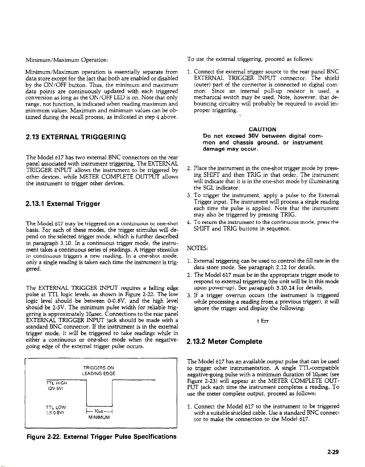
Minimum/Maximum Operation:
To use the external triggering, proceed as follows:
Minimum/Maximum operation is essentially separate from
data store except for the fact that both are enabled or disabled
by the ON/OFF button. Thus, the minimum and maximum
data points are continuously updated with each triggered
conversion as long as the ON/OFF LED is on. Note that only
range, not function, is indicated when reading maximum and
minimum values. Maximum and minimum values can be obtained during the recall process, as indicated in step 4 above.
2.13 EXTERNAL TRIGGERING
The Model 617 has two external BNC connectors on the rear
panel associated with instrument triggering. The EXTERNAL
TRIGGER INPUT allows the instrument to be triggered by
other devices, while METER COMPLETE OUTPUT allows
the instrument to trigger other devices.
2.13.1 External Trigger
The Model 617 may be triggered on a continuous or one-shot
basis. For each of these modes, the trigger stimulus will depend on the selected trigger mode, which is further described
in paragraph 3.10. In a continuous trigger mode, the instrument takes a continuous series of readings. A trigger stimulus
in continuous triggers a new reading. In a one-shot mode,
only a single reading is taken each time the instrument is triggered
The EXTERNAL TRIGGER INPUT requires a falling edge
pulse at ‘ITL logic levels, as shown in Figure 2-22. The low
logic level should be between O-O.&‘, and the high level
should be 2-5V. The minimum pulse width for reliable trig-
gering is approximately lO+ec. Connections to the rear panel
EXTERNAL TRIGGER INPUT jack should be made with a
standard BNC connector. If the instrument is in the external
trigger mode, it will be triggered to take readings while in
either a continuous or one-shot mode when the negative-
going edge of the external trigger pulse occurs.
1. Connect the external trigger source to the rear panel BNC
EXTERNAL TRIGGER INPUT connector. The shield
(outer) part of the connector is connected to digital common. Since an internal pull-up resistor is used, a
mechanical switch may be used. Note, however, that debouncing circuitry will probably be required to avoid im-
proper triggering.
CAUTION
Do not exceed 30V between digital common and chassis ground, or instrument
damage may occur.
2. Place the instrument in the one-shot trigger mode by pressing SHIFT and then TRIG in that order. The instrument
will indicate that it is in the one-shot mode by illuminating
the SGL indicator.
3. To trigger the instrument, apply a pulse to the External
Trigger input. The instrument will process a single reading
each time the pulse is applied. Note that the instrument
may also be triggered by pressing TRIG.
4. To return the instrument to the continuous mode, press the
SHIFT and TRIG buttons in sequence.
NOTES:
1. External triggering can be used to control the fill rate in the
data store mode. See paragraph 2.12 for details.
2. The Model 617 must be in the appropriate trigger mode to
respond to external triggering (the unit will be in this mode
upon power-up). See paragraph 3.10.14 for details.
3. If a trigger overrun occurs (the instrument is triggered
while processing a reading from a previous trigger), it will
ignore the trigger and display the following:
t En
2.13.2 Meter Complete
Figure 2-22. External Trigger Pulse Specifications
The Model 617 has an available output pulse that can be used
to trigger other instrumentation. A single lTL-compatible
negative-going pulse with a minimum duration of 10~sec (see
Figure 2-23) will appear at the METER COMPLETE OUTPUT jack each time the instrument completes a reading. To
use the meter complete output, proceed as follows:
1. Connect the Model 617 to the instrument to be triggered
with a suitable shielded cable. Use a standard BNC connector to make the connection to the Model 617.
2-29
Page 49
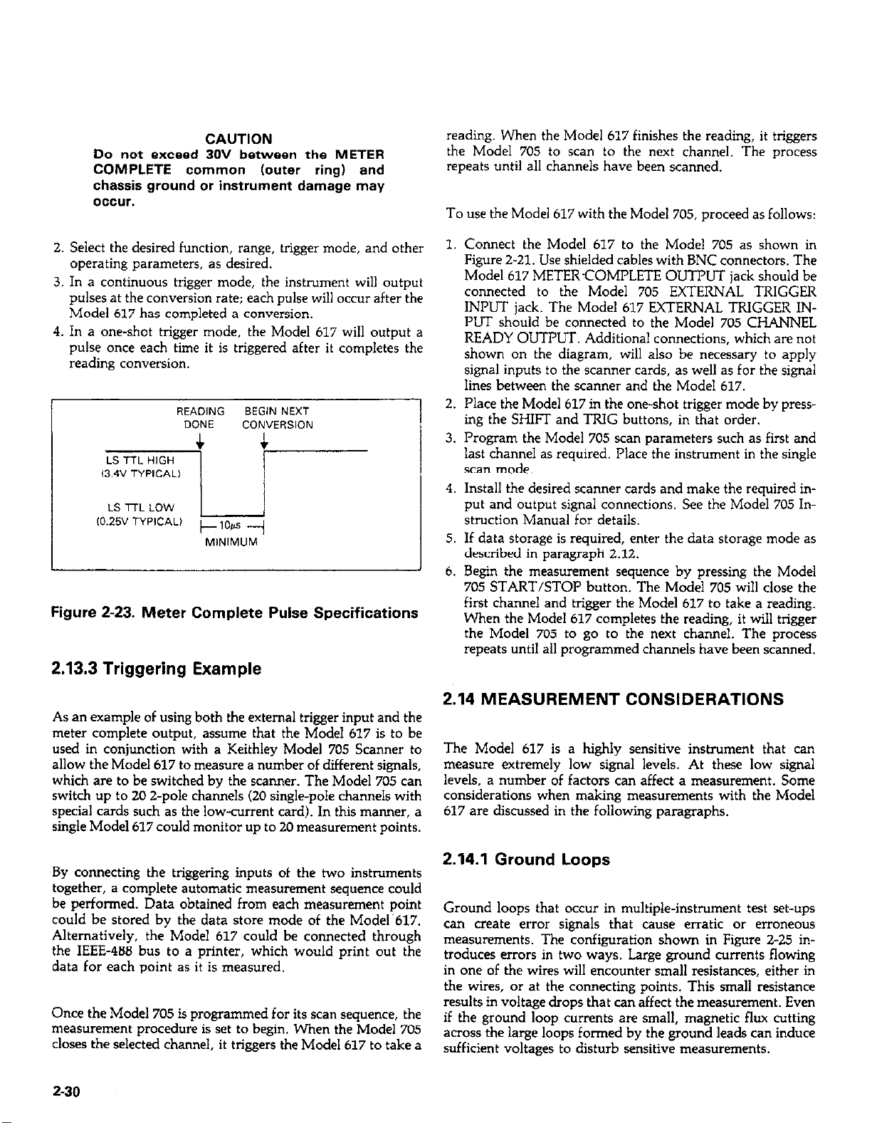
CAUTION
Do not exceed 30V between the METER
COMPLETE ccmmcn (outer ring) and
chassis ground or instrument damage may
OCCW.
reading. When the Model 617 finishes the reading, it triggers
the Model 705 to scan to the next channel. The process
repeats until all channels have been scanned.
To use the Model 617 with the Model 705, proceed as follows:
2. Select the desired function, range, trigger mode, and other
operating parameters, as desired.
3. In a continuous trigger mode, the instrument will output
pulses at the conversion rate; each pulse will occur after the
Model 617 has completed a conversion.
4. In a one-shot trigger mode, the Model 617 will output a
pulse once each time it is triggered after it completes the
reading conversion.
Figure 2-23. Meter Complete Pulse Specifications
2.13.3 Triggering Example
1. Connect the Model 617 to the Model 705 as shown in
Figure Z-21. Use shielded cables with BNC connectors. The
Model 617 METERCOMPLETE OUTPUT jack should be
connected to the Model 705 EXTERNAL TRIGGER
INPUT jack. The Model 617 EXTERNAL TRIGGER INPUT should be connected to the Model 705 CHANNEL
READY OUTPLIT Additional connections, which are not
shown on the diagram, will also be necessary to apply
signal inputs to the scanner cards, as well as for the signal
lines between the scanner and the Model 617.
2. Place the Model 617 in the one-shot trigger mode by pressing the SHIFT and TRIG buttons, in that order.
3. Program the Model 705 scan parameters such as first and
last channel as required. Place the instrument in the single
scan mode.
4. Install the desired scanner cards and make the required input and output signal connections. See the Model 705 Instruction Manual for details.
5. If data storage is required, enter the data storage mode as
described in paragraph 2.12.
6. Begin the measurement sequence by pressing the Model
705 START/STOP button. The Model 705 will close the
first channel and trigger the Model 617 to take a reading.
When the Model 617 completes the reading, it will trigger
the Model 705 to go to the next channel. The process
repeats until all programmed channels have been scanned.
As an example of using both the external trigger input and the
meter complete output, assume that the Model 617 is to be
used in conjunction with a Keithley Model 705 Scanner to
allow the Model 617 to measure a number of different signals,
which are to be switched by the scanner. The Model 705 can
switch up to 20 2-pole channels (20 single-pole channels with
special cards such as the low-current card). In this manner, a
single Model 617 could monitor up to 20 measurement points.
By connecting the triggering inputs of the two instruments
together, a complete automatic measurement sequence could
be performed. Data obtained from each measurement point
could be stored by the data store mode of the Model.617.
Alternatively, the Model 617 could be connected through
the IEEE-488 bus to a printer, which would print out the
data for each point as it is measured.
Once the Model 705 is programmed for its scan sequence, the
measurement procedure is set to begin. When the Model 705
closes the selected channel, it triggers the Model 617 to take a
Z-30
2.14 MEASUREMENT CONSIDERATIONS
The Model 617 is a highly sensitive instrument that can
measure extremely low signal levels. At these low signal
levels, a number of factors can affect a measurement. Some
considerations when making measurements with the Model
617 are discussed in the following paragraphs.
2.14.1 Ground Loops
Ground loops that occur in multiple-instrument test set-ups
can create error signals that cause erratic or erroneous
measurements. The configuration shown in Figure 2-25 in-
troduces errors in two ways. Large ground currents flowing
in one of the wires will encounter small resistances, either in
the wires, or at the connecting points. This small resistance
results in voltage drops that can affect the measurement. Even
if the ground loop currents are small, magnetic flux cutting
across the large loops formed by the ground leads can induce
sufficient voltages to disturb sensitive measurements.
Page 50
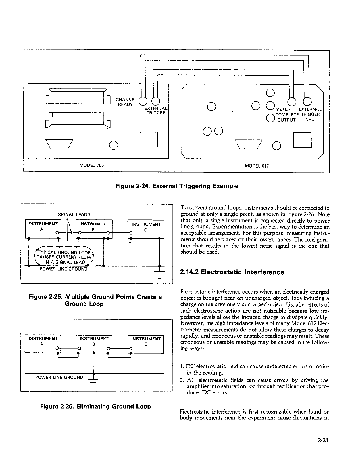
r
I
------\
r;YPlCAL GROUND LOOP,
(CAUSES CURRENT FLOW
. IN A SIGNAL LEAD,/
POWER LINE GROUND
MODEL 705
INSTRUMENT
s
00
Figure 2-24. External Triggering Example
To prevent ground loops, instruments should be connected to
ground at only a single point, as shown in Figure Z-26. Note
INSTRUMENT
I
T
-
that only a single instrument is connected directly to power
line ground. Experimentation is the best way to determine an
acceptable arrangement. For this purpose, measuring instruments should be placed on their lowest ranges. The configuration that results in the lowest noise signal is the one that
should be used.
2.14.2 Electrostatic Interference
MODEL 617
COMPLETE TRIGGER
OUTPUT
0
INPUT
Figure 2-25. Multiple Ground Points Create a
Ground Loop
INSTRUMENT
POWER LINE GROUND
INSTRUMENT
_
-
INSTRUMENT
Figure 2-26. Eliminating Ground Loop
Electrostatic interference occurs when an electrically charged
object is brought near an uncharged object, thus inducing a
charge on the previously uncharged object. Usually, effects of
such electrostatic action are not noticable because low impedance levels allow the induced charge to dissipate quickly.
However, the high impedance levels of many Model 617 Electrometer measurements do not allow these charges to decay
rapidly, and erroneous or unstable readings may result. These
erroneous or unstable readings may be caused in the following ways:
1. DC electrostatic field can cause undetected errors or noise
in the reading.
2. AC electrostatic fields can cause errors by driving the
amplifier into saturation, or through rectification that produces DC errors.
Electrostatic interference is first recognizable when hand or
body movements near the experiment cause fluctuations in
2-31
Page 51
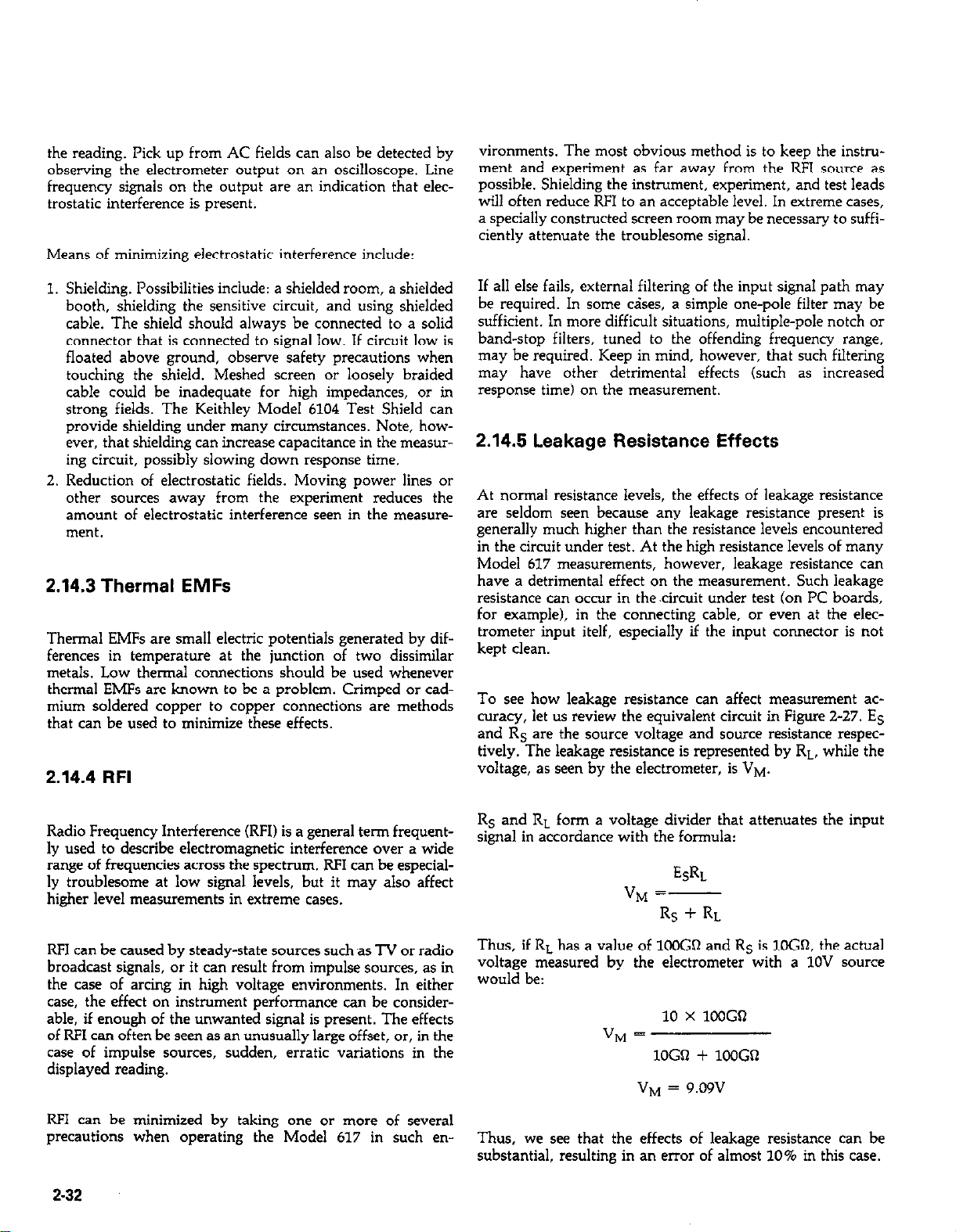
the reading. Pick up from AC fields can also be detected by
observing the electrometer output on an oscilloscope. Line
frequency signals on the output are an indication that electrostatic interference is present.
Means of minimizing electrostatic interference include:
vironments. The most obvious method is to keep the instrument and experiment as far away from the RF1 source as
possible. Shielding the instrument, experiment, and test leads
will often reduce RF1 to an acceptable level. In extreme cases,
a specially constructed screen room may be necessary to sufficiently attenuate the troublesome signal.
Shielding. Possibilities include: a shielded room, a shielded
booth, shielding the sensitive circuit, and using shielded
cable. The shield should always be connected to a solid
connector that is connected to signal low. If circuit low is
floated above ground, observe safety precautions when
touching the shield. Meshed screen or loosely braided
cable could be inadequate for high impedances, or in
strong fields. The Keithley Model 6104 Test Shield can
provide shielding under many circumstances. Note, however, that shielding can increase capacitance in the measuring circuit, possibly slowing down response time.
Reduction of electrostatic fields. Moving power lines or
other sources away from the experiment reduces the
amount of electrostatic interference seen in the measurement.
2.14.3 Thermal EMFs
Thermal EMFs are small electric potentials generated by differences in temperature at the junction of two dissimilar
metals. Low thermal connections should be used whenever
thermal EMFs are known to be a problem. Crimped or cad-
mium soldered copper to copper connections are methods
that can be used to minimize these effects.
2.14.4 RFI
If all else fails, external filtering of the input signal path may
be required. In some &es, a simple one-pole filter may be
sufficient. In more difficult situations, multiple-pole notch or
band-stop filters, tuned to the offending frequency range,
may be required. Keep in mind, however, that such filtering
may have other detrimental effects (such as increased
response time) on the measurement.
2.14.5 Leakage Resistance Effects
At normal resistance levels, the effects of leakage resistance
are seldom seen because any leakage resistance present is
generally much higher than the resistance levels encountered
in the circuit under test. At the high resistance levels of many
Model 617 measurements, however, leakage resistance can
have a detrimental effect on the measurement. Such leakage
resistance can occur in the-circuit under test (on PC boards,
for example), in the connecting cable, or even at the electrometer input itelf, especially if the input connector is not
kept clean.
To see how leakage resistance can affect measurement accuracy, let us review the equivalent circuit in Figure 2-27. Es
and Rs are the source voltage and source resistance respectively. The leakage resistance is represented by RL, while the
voltage, as seen by the electrometer, is VM.
Radio Frequency Interference (RFI) is a general term frequently used to describe electromagnetic interference over a wide
range of frequencies across the spectrum. RF1 can be especially troublesome at low signal levels, but it may also affect
higher level measurements in extreme cases.
RF1 can be caused by steady-state sources such as TV or radio
broadcast signals, or it can result from impulse sources, as in
the case of arcing in high voltage environments. In either
case, the effect on instrument performance can be consider-
able, if enough of the unwanted signal is present. The effects
of RF1 can often be seen as an unusually large offset, or, in the
case of impulse sources, sudden, erratic variations in the
displayed reading.
RF1 can be minimized by taking one or more of several
precautions when operating the Model 617 in such en-
2-32
Rs and RL form a voltage divider that attenuates the input
signal in accordance with the formula:
ML
viq =-
Rs + RL
Thus, if RL has a value of lCOGQ and Rs is lOGQ, the actual
voltage measured by the electrometer with a 1OV source
would be:
10 x 1WGSl
VM =
1OGQ + 1WGQ
vp”j = 9.09v
Thus, we see that the effects of leakage resistance can be
substantial, resulting in an error of almost 10% in this case.
Page 52
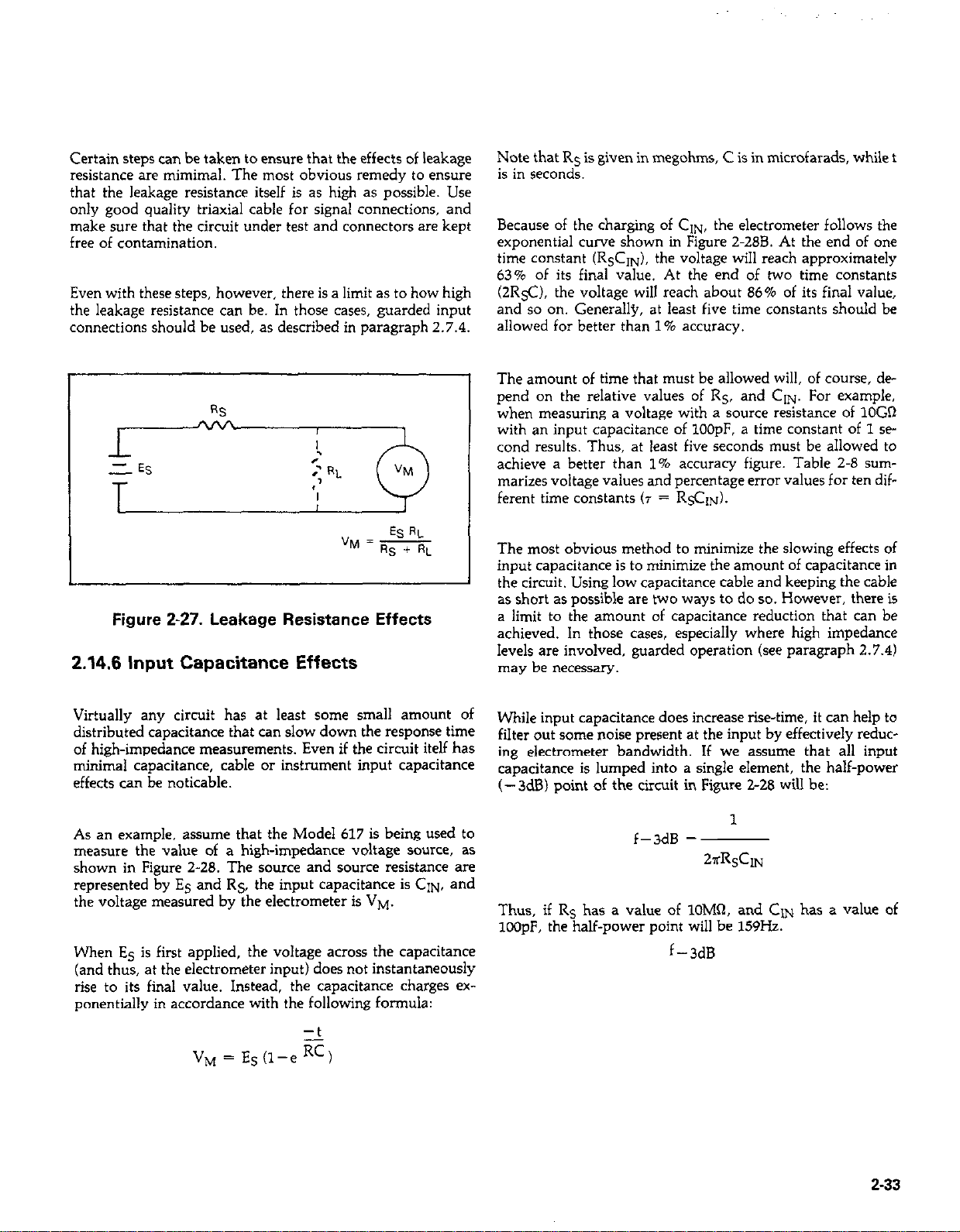
Certain steps can be taken to ensure that the effects of leakage
resistance are mimimal. The most obvious remedy to ensure
that the leakage resistance itself is as high as possible. Use
only good quality triaxial cable for signal connections, and
make sure that the circuit under test and connectors are kept
free of contamination.
Even with these steps, however, there is a limit as to how high
the leakage resistance can be. In those cases, guarded input
connections should be used, as described in paragraph 2.7.4.
Note that Rs is given in megohms, C is in microfarads, while t
is in seconds.
Because of the charging of GIN, the electrometer follows the
exponential curve shown in Figure 2.288. At the end of one
time constant (R&IN), the voltage will reach approximately
63% of its final value. At the end of two time constants
(2R5C). the voltage will reach about 86% of its final value,
and so on. Generally, at least five time constants should be
allowed for better than 1% accuracy.
The amount of time that must be allowed will, of course, de
pend on the relative values of R5, and GIN. For example,
when measuring a voltage with a source resistance of 1OGR
with an input capacitance of 100pF. a time constant of 1 se
cond results. Thus, at least five seconds must be allowed to
achieve a better than 1% accuracy figure. Table 2-8 sum-
marizes voltage values and percentage error values for ten different time constants (T = R$ZIN).
")J = -
ESRL
Rs + RL
Figure Z-27. Leakage Resistance Effects
2.14.6 Input Capacitance Effects
Virtually any circuit has at least some small amount of
distributed capacitance that can slow down the response time
of high-impedance measurements. Even if the circuit itelf has
minimal capacitance, cable or instrument input capacitance
effects can be noticable.
As an example, assume that the Model 617 is being used to
measure the value of a high-impedance voltage source, as
shown in Figure 2-28. The source and source resistance are
represented by E5 and R5, the input capacitance is GIN, and
the voltage measured by the electrometer is VM.
When E5 is first applied, the voltage across the capacitance
(and thus, at the electrometer input) does not instantaneously
rise to its final value. Instead, the capacitance charges exponentially in accordance with the following formula:
The most obvious method to minimize the slowing effects of
input capacitance is to minimize the amount of capacitance in
I
I
the circuit. Using low capacitance cable and keeping the cable
as short as possible are two ways to do so. However, there is
a limit to the amount of capacitance reduction that can be
achieved. In those cases, especially where high impedance
levels are involved, guarded operation (see paragraph 2.7.4)
may be necessary.
While input capacitance does increase rise-time, it can help to
filter out some noise present at the input by effectively reduc-
ing electrometer bandwidth. If we assume that all input
capacitance is lumped into a single element, the half-power
(- 3dB) point of the circuit in Figure Z-28 will be:
1
f-3dB =
~~RsCIN
Thus, if Rs has a value of lOM’J, and CON has a value of
lCOpF, the half-power point will be 159Hz.
f-3dB
2-33
Page 53

Table 2-8. Voltage and Percent Error For Various
Time Constants
/Time* 1 VM / % Error
7 IO.632 Es / 36
%
Figure 2-29. Simplified Model for Source
Resistance and Source Capacitance
Effects
A. CIRCUIT
h?
0.632 ES
kL
RSCIN
6. EXPONENTIAL RESPONSE
Figure 2-28. Input Capacitance Effects
2.14.7 Source Resistance
As shown in Table 2-9, a minimum value of source resistance
is recommended for each AMPS range. The reason for this
can be understood by examining Figure 2-29. Considering ef-
fects on low frequency noise and drift, Cs and CF can
momentarily be ignored.
Table 2-9. Minimum Recommended Source Resis-
tance Values in Amps
Minimum Source
Range I
All pA 1
All mA
Input amplifier noise and drift appearing at the output can be
calculated as follows:
Equation 1.
Output Enoise
Thus it is clear that as long as Rs>> RF, Output E,,ise = Input En,,ire. When RF = Rs, output Enoh = 2 X Input Enoie.
= Input En+ X (1 +-)
Resistance
lOOGil
1OOMQ
100 kQ
100 n
RF
Rs
2-34
Page 54
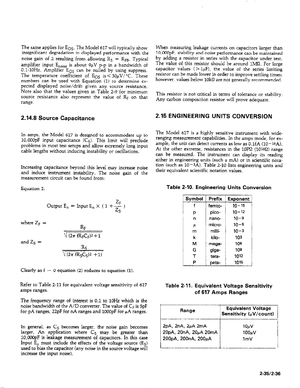
The same applies for EOS. The Model 617 will typically show
insignificant degradation in displayed performance with the
noise gain of 2 resulting from allowing Rg = Rm. Typical
amplifier input E,,ise is about 9pV p-p in a bandwidth of
0.1.1OHz. Amplifier EOS can be nulled by using suppress.
The temperature coefficient of Eos is< 304~V/“C. These
numbers can be used with Equation (1) to determine expected displayed noise/drift given any source resistance.
Note also that the values given in Table 2-9 for minimum
source resistance also represent the value of RF on that
range.
When measuring leakage currents on capacitors larger than
lO,OOOpF, stability and noise performance can be maintained
by adding a resistor in series with the capacitor under test.
The value of this resistor should be around 1MQ. For large
capacitor values (> lpF), the value of the series limiting
resistor can be made lower in order to improve settling times;
however, values below 10kR are not generally recommended.
This resistor is not critical in terms of tolerance or stability.
Any carbon composition resistor will prove adequate.
2.14.8 Source Capacitance
In amps, the Model 617 is designed to accommodate up to
10,OOOpF input capacitance CC,). This limit will preclude
problems in most test setups and allow extremely long input
cable lengths without inducing instability or oscillations.
Increasing capacitance beyond this level may increase noise
and induce instrument instability. The noise gain of the
measurement circuit can be found from:
Equation 2.
Output E, = Input E, x ( 1 +$ )
where ZF =
RF
\I (2a fRpC# + 1
and Zs =
RS
vGziifRSCs)2 +u
Clearly as f - 0 equation (2) reduces to equation (1)
2.15 ENGINEERING UNITS CONVERSION
The Model 617 is a highly sensitive instrument with wideranging measurement capabilities. In the amps mode, for example, the unit can detect currents as low as O.lfA (lo--lbA).
At the other extreme, resistances in the 1OMl (10160) range
can be measured. The instrument can display its reading
either in engineering units (such a mA) or in scientific notation (such as lo-3A). Table 2-10 lists engineering units and
their equivalent scientific notation values.
Table 2-10. Engineering Units Conversion
Symbol 1 Prefix Exponent
f
/ femto- 1 lo-15
P
”
h
ml
k
M
G
T
P
i
pico-
“S”O-
milli-
kilo-
mega-
giga-
tera-
peta-
10-v
10-S
10-G
10-3
103
106
109
1012
1015
Refer to Table 2-11 for equivalent voltage sensitivity of 617
amps ranges.
The frequency range of interest is 0.1 to lOI& which is the
noise bandwidth of the A/D converter. The value of CF is 5pF
for pA ranges, 22pF for nA ranges and 1CGOpF for pA ranges.
In general, as Cs becomes larger, the noise gain becomes
larger. An application where Cs may be greater than
10,COOpF is leakage measurement of capacitors. In this case
Input E, must include the effects of the voltage source (Es)
used to bias the capacitor (any noise in the source voltage will
increase the input noise).
Table 2-11. Equivalent Voltage Sensitivity
of 617 Amps Ranges
Range
c
2pA, 2nA. 2pA 2mA
ZOpA, 20nA. ~OJLA 20mA
200pA. 2OOnA, 200pA
Sensitivity hV/count)
---.-
1
-
2-3512-36
Page 55
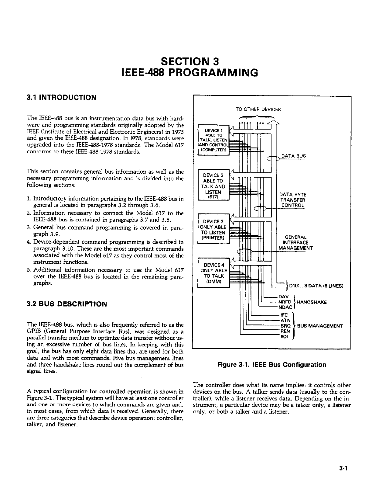
SECTION 3
IEEE-488 PROGRAMMING
3.1 INTRODUCTION
The IEEE-488 bus is an instrumentation data bus with hardware and programming standards originally adopted by the
IEEE (Institute of Electrical and Electronic Engineers) in 1975
and given the IEEE488 designation. In 1978, standards were
upgraded into the IEEE-488-1978 standards. The Model 617
conforms to these IEEE-488.1978 standards.
This section contains general bus information as well as the
necessary programming information and is divided into the
following sections:
1. Introductory information pertaining to the IEEE-488 bus in
general is located in paragraphs 3.2 through 3.6.
2. Information necessary to connect the Model 617 to the
IEEE-486 bus is contained in paragraphs 3.7 and 3.8.
3. General bus command programming is covered in paragraph 3.9.
4. Devicedependent command programming is described in
paragraph 3.10. These are the most important commands
associated with the Model 617 as they control most of the
instrument functions.
5. Additional information necessary to use the Model 617
over the IEEE-488 bus is located in the remaining paragraphs.
3.2 BUS DESCRIPTION
The IEEE-488 bus, which is also frequently referred to as the
GPIB (General Purpose Interface Bus), was designed as a
parallel transfer medium to optimize data transfer without us-
ing an excessive number of bus lines. In keeping with this
goal, the bus has only eight data lines that are used for both
data and with most commands. Five bus management lines
and three handshake lines round out the complement of bus
signal lines.
A typical configuration for controlled operation is shown in
Figure 3-l. The typical system will have at least one controller
and one or more devices to which commands are given and,
in most cases, from which data is received. Generally, there
are three categories that describe device operation: controller,
talker, and listener.
Figure 3-1. IEEE Bus Configuration
The controller does what its name implies: it controls other
devices on the bus. A talker sends data (usually to the con-
troller), while a listener receives data. Depending on the instrument, a particular device may be a talker only, a listener
only, or both a talker and a listener.
3-l
Page 56
There are two categories of controllers: system controller,
and basic controller. Both are able to control other instruments, but only the system controller has the absolute
authority in the system. In a system with more that one con-
troller, only one controller may be active at any given time.
Certain protocol is used to pass control from one controller to
another.
The IEEE-488 bus is limited to 15 devices, including the con-
troller. Thus, any number of talkers and listeners up to that
limit may be present on the bus at one time. Although several
devices may be commanded to listen simultaneously, the bus
can have only one active talker, or communications would be
scrambled.
A device is placed in the talk or listen state by sending an appropriate talk or listen command. These talk and listen com-
mands are derived from an instrument’s primary address. The
primary address may have any value between 0 and 30, and is
generally set by rear panel DIP switches or programmed in
from the front panel of the instrument. The actual listen ad-
dress .value sent out over the bus is obtained by ORing the
primary address with $20. For example, if the primary ad-
dress is 27 ($lB), the actual listen address is $3B ($38 = $lB
+ $20). In a similar manner, the talk address is obtained bv
OR& the primary address value with $40. With the present
example, the talk address derived from a primary address of
27 decimal would be $5B ($SB = $lB -t $40)
The IEEE-488 standards also include another addressing mode
called secondary addressing. Secondary addresses lie in the
range of $60-$7F. Note, however, that many devices do not
use secondary addressing.
3.3.1 Data Lines
The IEEE-488 bus uses eight data lines that allow data to be
transmitted and received in a bit-parallel, byte serial manner.
These lines use the convention DIOl-DIOS instead of the
more common DO-D7. DIOl is the least significant bit, while
DIOS is the most significant bit. The data lines are bidirectional (with most devices), and, as with the remaining lines,
low is considered to be true.
3.3.2 Bus Management Lines
The five bus management lines help to ensure proper interface
control and management. These lines are used to send the
uniline commands that are described in paragraph. 3.4.1.
ATN (Attention)-The ATN line is one of the more important management lines in that the state of this line determines
how information on the data bus is to be interpreted.
IFC (Interface Clear&As the name implies, the IFC line con-
trols clearing of instruments from the bus.
REN (Remote Enable&The REN line is used to place instrument on the bus in the remote mode.
EOI (End or Identify&The EOI line is usually used to mark
the end of a multi-byte data transfer sequence.
SRQ (Service Request)-This line is used by devices when
they require service from the controller.
Once the device is properly addrwed, appropriate bus transactions are set to take place. For example, if an instrument is
addressed to talk, it will usually place its data byte on the bus
one byte at a time. The listening device (frequently the controller) will then read this information.
3.3 IEEE-488 BUS LINES
The signal lines on the IEEE-488 bus are grouped into three
different categories: data lines, management lines, and handshake lines. The data lines handle bus data and commands,
while the management and handshake lines ensure that
proper data transfer and bus operation takes place. Each bus
iine.is active low, with approximately zero v&s representing
a logic 1 (true). The following paragraphs describe the purpose of these lines, which are shown in Figure 3-l.
3-2
3.3.3 Handshake Lines
The bus uses handshake lines that operate in an interlocked
sequence. This method ensures reliable data transmission ms method ensures reliable data transmission
..6YA....00 ,f the transfer rate. Generally, data transfer will regardless of the transfer rate. Generally, data transfer will
occur at a rate determined by the slowest active device on the occur at a rate determined by the slowest active device on the
bus
One of the three handshake lines is controlled by the source
(the talker sending information), while the remaining two
lines are controlled by accepting devices (the listener or
listeners ret-‘..‘-- ’ S~~UZS rhe information
lines are:
DAV (Data Valid&The source controls the state of the DAV
line to indicate to any listening devices whether or not data
bus information is valid.
x*e lines that operate in an mterlockza
0. The three handshake
Page 57
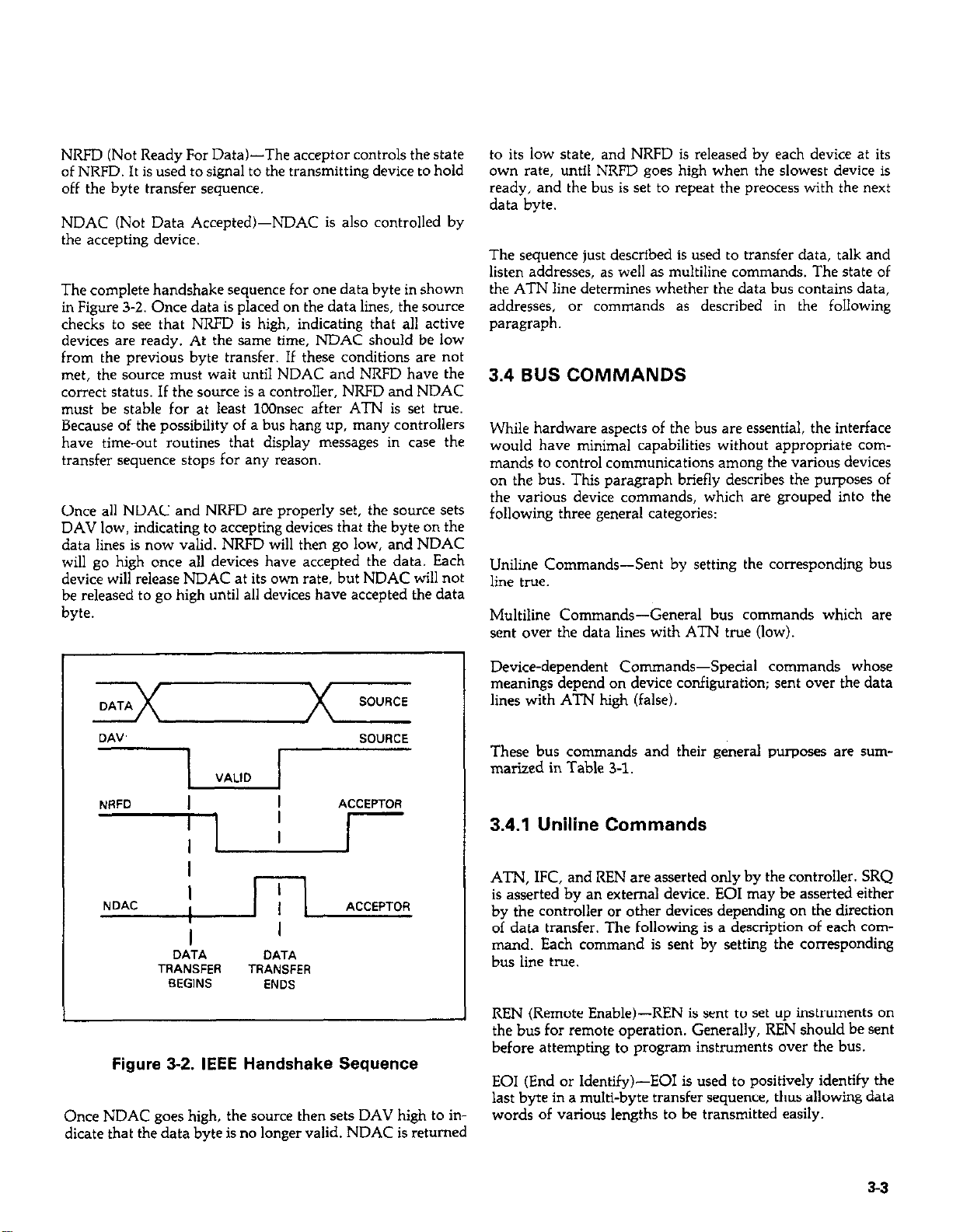
NRFD (Not Ready For Data&The acceptor controls the state
of NRFD. It is used to signal to the transmitting device to hold
off the byte transfer sequence.
NDAC (Not Data Accepted)-NDAC is also controlled by
the accepting device.
The complete handshake sequence for one data byte in shown
in Figure 3-Z. Once data is placed on the data lines, the source
checks to see that NRFD is high, indicating that all active
devices are ready. At the same time, NDAC should be low
from the previous byte transfer. If these conditions are not
met, the source must wait until NDAC and NRFD have the
correct status. If the source is a controller, NRFD and NDAC
must be stable for at least 1OOnsec after ATN is set true.
Because of the possibility of a bus hang up, many controllers
have time-out routines that display messages in case the
transfer sequence stops for any reason.
Once all NDAC and NRFD are properly set, the source sets
DAV low, indicating to accepting devices that the byte on the
data lines is now valid. NRFD will the” go low, and NDAC
will go high once all devices have accepted the data. Each
device will release NDAC at its own rate, but NDAC will not
be released to go high until all devices have accepted the data
byte
to its low state, and NRFD is released by each device at its
own rate, until NRFD goes high when the slowest device is
ready, and the bus is set to repeat the preocess with the next
data byte.
The sequence just described is used to transfer data, talk and
listen addresses, as well as multiline commands. The state of
the ATN line determines whether the data bus contains data,
addresses, or commands as described in the following
paragraph.
3.4 BUS COMMANDS
While hardware aspects of the bus are essential, the interface
would have minimal capabilities without appropriate commands to control communications among the various devices
on the bus. This paragraph briefly describes the purposes of
the various device commands, which are grouped into the
following three general categories:
Uniline Commands-Sent by setting the corresponding bus
line true.
Multiline Commands-General bus commands which are
sent over the data lines with ATN true (low).
DA”’
NRFD
VALID
I
I
I
SOURCE
ACCEPTOR
I
NDAC
I
I
,
I
DATA
TRANSFER
BEGINS
ACCEPTOR
I
DATA
TRANSFER
ENDS
Figure 3-2. IEEE Handshake Sequence
Once NDAC goes high, the source then sets DAV high to indicate that the data byte is no longer valid. NDAC is returned
Device-dependent Commands-Special commands whose
meanings depend on device configuration; sent over the data
lines with ATN high (false).
These bus commands and their general purposes are surnmarized in Table 3-l.
3.4.1 Uniline Commands
ATN, IFC, and REN are asserted only by the controller. SRQ
is asserted by a” external device. EOI may be asserted either
by the controller or other devices depending on the direction
of data transfer. The following is a description of each command. Each command is sent by setting the corresponding
bus line true.
REN (Remote Enable)-REN is sent to set up instruments on
the bus for remote operation. Generally, REN should be sent
before attempting to program instruments over the bus.
EOI (End or Identify&E01 is used to positively identify the
last byte in a multi-byte transfer sequence, thus allowing data
words of various lengths to be transmitted easily.
53
Page 58

IFC (Inter&z Clear)-IFC is used to clear the interface and
return all devices to the talker and listener idle states.
ATN (Attention)-The controller sends ATN while transmit-
ting addresses or multiline commands.
SRQ (Service Request)-SRQ is asserted by a device when it
requires service from a controller.
3.4.2 Universal Commands
Universal commands are those multiline commands that require no addressing. All devices equipped to implement such
commands will do so simultaneously when the command is
transmitted. As with all multiline commands, these commands are transmitted with ATN true.
SPD (Serial Poll Disable)-SPD is used by the controller to
remove a11 devices on the bus from the serial poll mode and is
generally the last command in the serial polling sequence.
3.4.3 Addressed Commands
Addressed commands are multiline commands that must be
preceded by the devici listen address before that instrument
will respond to the command in question. Note that only the
addressed device will respond to these commands:
SDC (Selective Device Clear)-The SDC command performs
essentially the same function as the DCL command except
that only the addressed device responds. Generally, instruments return to their power-up default conditions when
responding to the SDC command.
LLO (Local Lockou+LLO is sent to instruments to lock out
their front panel controls.
DCL (Device Clear)-DCL is used to return instruments to
some default state. Usually, instruments return to their
power-up conditions.
SPE 6xial Poll Enable)-SPE is the first step in the serial
polling sequence, which is used to determine which device has
requested service.
Table 3-l. IEEE-488 Bus Command Summaw
Command Type Command
Uniline REN (Remote Enable)
EOI
IFC (Interface Clear)
ATN (Attention)
SRQ
Multiline
Universal LLO (Local Lockout)
DCL (Device Clear)
SPE (Serial Poll Enable)
SPD (Serial Poll Disable)
Addressed SDC (Selective Device Clear) !
GTL (Go To Local)
GET (Group Execute Trigger)
Unaddressed UNL (Unlisten)
UNT Wntalk)
Device-dependent”*
GTL (Go To Local&The GTL command is used to remove
instruments from the remote mode. With some instruments,
GTL also unlocks front panel controls if they were previously
locked out with the LLO command.
GET (Group Execute Trigger)-The GET command is used to
trigger devices to perform a specific action that depends on
device configuration (for example, take a reading). Although
GET is an addressed command, many devices respond to
GET without addressing.
State of
ATN Line” Comments
X Set up for remote operation.
X Marks end of transmission.
X Clears Interface
LOW Defines data bus contents.
X Controlled by external device.
Low
Low
Locks out front panel controls.
Returns device to default conditions.
LOW Enables serial polling.
LOW Disables serial polling.
LOW Returns unit to default conditions.
LOW Sends go to local.
Low Triggers device for reading.
Low
LOW
Removes all lineners from bus.
Removes any talkers from bus.
High Programs Model 617 for various modes.
34
*Don’t Care.
**See paragraph 3.10 for complete description.
Page 59

3.4.4 Unaddress Commands
purposes only; the Model 617 does not have secondary addressing capabilities.
The two unaddress commands are used by the controller to
remove any talkers or listeners from the bus. ATN is true
when these commands are asserted.
UNL (LJnlisten)-Listeners are placed in the listener idle state
by the UNL command.
UNT (Untalk)-Any previously commanded talkers will be
placed in the talker idle state by the UNT command.
3.4.5 Device-Dependent Commands
The meaning of the device-dependent commands will depend
on the configuration of the instrument. Generally, these com-
mands are sent as one or more ASCII characters that tell the
device to perform a specific function. For example, the command sequence FOX is used to place the Model 617 in the volts
mode. The IEEE-486 bus actually treats these commands as
data in that ATN is false when the commands are transmit-
ted.
3.5 COMMAND CODES
Each multiline command is given a unique code that that is
transmitted over the bus as 7 bit ASCII data. This section
briefly explains the code groups, which are summarized in
Figure 3-3.
Note that these commands are normally transmitted with the
7 bit code listed in Figure 3-3. For many devices, the condition
of DI08 is unimmxtant. However. manv devices mav reouire
I
, .
that DI08 has a value of logic 0 (high) to properly send commands.
Hexadecimal and decimal values for each of the commands or
command groups are listed in Table 3-2. Each value assumes
that DI08 has a value of 0.
Table 3-2. Hexadecimal and Decimal Command
Codes
hmmand
GIL
SDC
GET
LLO
DCL
SPE
SPD
LAG
TAG
UNL
UNT
Hex Value
1
01
04
08
11
14
18
19
20.3F
40-5F
3F
5F
Decimal Value
1
4
8
17
20
24
25
32-63
64-95
63
95
Addressed Command Group (ACG)-Addressed commands
an* co*esp0n*1ng ASCII codes are listed in cohxnns WA,
. .--_. . . . . . _I.~
and O(B).
Universal Command Group (UCG)--Universal commands
and values are listed in columns l(A) and l(B).
Listen Address Group (LAG)-Columns 2(A) through 3(B)
list codes for commands in this address group. For example, if
the primary address of the instrument is 27, the LAG byte will
be an ASCII left bracket.
Talk Address Group (TAG)-TAG primary address values
and corresponding ASCII characters are listed in columns
4(A) through 5(B).
The preceding address groups are combined together to form
the Primary Command Group (KG). The bus also has
another group of commands, called the Secondary Command
Group (SCG). These are listed in Figure 3-3 for informational
3.6 COMMAND SEQUENCES
The proper command sequence must be sent to the instrument before it will respond as intended. Universal commands, such as LLO and DCL, require only that ATN be set
low when sending the command. Other commands require
that the instrument be properly addressed to listen first. This
section briefy describes the bus sequence for several types of
commands.
3.6.1 Addressed Command Sequence
Before a device will respond to one of these commands, it
must receive a LAG command derived from its primary ad-
dress. Table 3-3 shows a typical sequence for the SDC command: the example assumes that a primary address of 27 is
being used.
3-5
Page 60

c
x
x
I
c
x
x
I
L
3-6
Page 61

Note that an IJNL command is generally sent before the LAG,
SDC sequence. This is usually done to remove all other
listeners from the bus so that the desired device responds to
the command.
Table 3-3. Typical Addressed Command Sequence
3.7 HARDWARE CONSIDERATIONS
Before the Model 617 can be operated over the IEEE-466 bus,
it must first be connected to the bus with a suitable cable.
Also, the primary address must be programmed to the correct
value, as described in the following paragraphs.
Data Bus
itep Command ATN State
1
2
3
4
UNL Set low ? 3F
LAG* stays low I 36
SDC stays low EOT 04
Returns high
ASCII Hex Decimal
63
59
4
“Assumes primary address=27.
3.6.2 Universal Command Sequence
Universal commands are sent by setting ATN low and then
placing the command byte on the data bus. ATN would then
remain low during the period the command is transmitted.
For example, if the LLO command were to be sent, both ATN
and LLO would be asserted simultaneously.
3.6.3 Device-Dependent Command Sequence
Device-dependent commands are transmitted with ATN
false. However, a device must be addressed to listen before
these commands are transmitted. Table 3-4 shows the byte se-
quence for a typical Model 617 command (FOX), which sets
the instrument for the volts mode of operation.
3.7.1 Typical Cohtrolled Systems
System configurations are many and varied and will depend
on the application. To obtain as much versatility as possible,
the IEEE-488 bus was designed so that additional instrumentation could be easily added. Because of this versatility,
system complexity can range from the very simple to ex-
tremely complex.
Figure 3-4 shows two possible system configurations. Figure
3-4(a) shows the simplest possible controlled system. The
controller is used to send commands to the instrument, which
sends data back to the controller.
The system in Figure 3-4(b) is somewhat more complex in that
additional instruments are used. Depending on programming, all data may be routed through the controller, or it may
be sent directly from one instrument to another.
In very complex applications, a larger computer could be used. Tape drives or disks could be used to store any data
generated by the instruments.
Table 34. Typical Device-Dependent Command
Sequence
-
Command
teP
i-
2
3
4
5
-
UNL
LAG”
Data
Data
Data
*Assumes primary address = 27.
[~j~E$
MODEL 617 CONTROLLER
IA, SIMPLE SYSTEM
CONTROLLER
IS, ADDITIONAL INSTRUMENTATION
Figure 3-4. System Types
3-7
Page 62

3.7.2 Bus Connections
The Model 617 is to be connected to the IEEE-486 bus through
a cable equipped with standard IEEE-486 connectors, an example of which is shown in Figure 3-5. The connector is
designed to be stacked to allow a number of parallel connections. Two screws are located on each connector to ensure
that connections remain secure. Current standards call for
metric threads, as identified by dark colored screws. Earlier
versions had different screws, which are silver colored. Do
not attempt to use these type of connectors with the Model
617, which is designed for metric threads.
3. Add additional connectors from other instruments, as required.
4. Make sure the other end of the cable is mouerlv connected
to the controller. Some controllers have a; IEEE-488 type
connector, while others do not. Consult the instruction
manual for your controller for the proper connecting
method.
INSTRUMENT
Figure 3-6. IEEE-488 Connections
INSTRUMENT
INSTRUMENl
CONTROLLER
Figure 3-5. IEEE-488 Connector
A typical connecting scheme for the bus is shown in Figure
3-6. Each cable normally has the standard connector on each
end. These connectors are designed to be stacked to allow a
number of parallel connections on one instrument.
NOTE
To avoid possible damage, it is recommended
that you stack no more than three connectors on
any one instrument.
Connect the Model 617 to the cable as follows:
NOTE
The IEEE-488 bus is limited to a maximum of 15
devices, including the controller. Also, the maxi-
mum cable length is limited to 20 meters, or 2
meters times the number of devices, which ever
is less. Failure to heed these limits may result in
erratic bus operation.
Custom cables may be constructed by using the information
in Table 3-5 and Figure 3-8. Table 3-5 lists the contact
assignments for the various bus lines,~ while Figure 3-8 shows
contact assignments.
CAUTION
The voltage between IEEE-488 common and
chassis ground must not exceed 30V or instrument damage may occur.
EEE 488 ,NTERFACE
ADDRESS ENTERED WITH
FRONT PANEL PROGRAM
r
1
1. Line up the connector on the cable with the connector on
the rear panel of the instrument. See Figure 3-7 for connec-
tor location.
2. Tighten the screws securely, but do not overtighten them.
3-g
3OV MAX
rf;r
Figure 3-7. 617 Rear Panel IEEE Connector
Page 63

Table 3-5. IEEE Contact Designations
3.7.3 Primary Address Programming
contact
Uumber
10
11
12
13
14
15 D107
16
17
18 Gnd, (6)*
19
20
21
22
23 Gnd, (111*
24
IEEE-488
Designation
1
DlOl
2
D102
3
D103
4
Di04
5 EOI 1241”
6
DAV
7
NRFD
8 NDAC
9 IFC
SRQ
ATN
SHIELD
D105
D106
D108
REN (24)’
Gnd, (7)*
Gnd, (8)”
Gnd, (9)”
Gnd, (101’
Gnd, LOGIC
Type
Data
Data
Data
Data
Management
Handshake
Handshake
Handshake
Management
Management
Management
Ground
Data
Data
Data
Data
Management
Ground
Ground
Ground
Ground
Ground
Ground
Ground
*Number in parenthesis refer to signal
ground return of referenced contact
number. EOI and REN signal lines return on
contact 24.
The Model 617 must receive a listen command before is will
respond to addressed commands. Similarly, the unit must
receive a talk command before it will transmit its data. The
Model 617 is shipped from the factory with a programmed
primary address of 27. Until you become more familiar with
your instrument, it is recommended that you leave the ad-
dress at this value be&se the programming examples includ-
ed in this manual a~wme that address.
The primary address may be set to any value between 0 and
30 as long as address conflicts with other instruments are
avoided. Note that controllers are also given a primary address, so you must be careful not to use that address either.
Most frequently, controller addresses are set to 0 or 21, but
you should consult the controller’s instruction manual for
details. Whatever primary address you choose, you must
make certain that it corresponds with the value specified as
part of the controller’s programming language.
To check the present primary address, or to change to a new
one, use the following sequence:
1. Press the PROGRAM SELECT button repeatedly until the
following message is displayed:
IEEE 27
2. This message indicates that the IEEE address program is
selected, along with the presently programmed value (in
this case, the default value of 27 is being displayed).
3. Using one of the V-SOURCE ADJUST buttons, scroll the
displayed address to the desired value (the display will
show special values for the talk-only mode, as described in
the next paragraph).
4. Exit the program by pressing SHIFT then SELECT EXIT.
The new address is now in effect, and it will remain programmed even if the power is turned off.
I
CONTACT 12 CONTACT 1 I
CONTiCT 24
Figure 3-8. Contact Assignments
CONiACT 13
NOTE
Each device on the bus must have a unique
primary address. Failure to observe this precaution will probably result in erratic bus operation.
3.7.4 Talk-Only Mode
I
The Model 617 may be placed into the talk-only mode and be
used with a listen-only device such as a printer. When in this
mode, the instrument will ignore commands given over the
bus and merely output data as requested by the listening
3-S
Page 64
device. When the instrument is in the talk-only mode, the
front panel TALK LED will turn on.
3.8 SOFIWARE CONSIDERATIONS
The instrument can be placed in the talk-only mode by entering one of the following parameters in the primary address
program:
40 Talk only mode with prefix on data string (Example:
NDCV--1.2345E-01
41 Talk only mode without prefix on data string (Example:
-1.2345E-01
To place the instrument in the talk-only mode, perform the
following steps:
1. Press the PROGRAM SELECT button so that the following message is displayed:
IEEE 27
2. Press the up arrow V-SOURCE ADJUST button repeated-
ly until the desired talk-only parameter (40 or 41) is
shown.
3. To exit the program, press SHIFT then SELECT EXIT. The
unit is now programmed for the talk-only mode, and it
will remain programmed in this manner even if the power
is turned off.
The data output rate in the talk-only mode can be selected as
follows:
There are a number of IEEE-488 controllers available, each of
which has its own programming language. Also, different instruments have differing capabilities. In this section, we will
discuss programming languages for two typical controllers:
the HP-85, and the IBM-PC interfaced to the bus through a
Keithley Model 8573 IEEE-488 interface. In addition, interface
functions codes that define Model 617 capabilities will be
discussed.
3.8.1 Controller Handler Software
Before a specific controller can be used over the IEEE-488 bus,
it must have IEEE-488 handler software installed. With some
controllers, the software is located in ROM, and no software
initialization is required on the part of the user. With other
controllers, software must be loaded from disk or tape and be
properly initialized. With the HP-85, for example, an additional I/O ROM that handles interface functions must be installed. With the Keithley Model 8573 interface for the IBMPC, software must be installed and configured from a
diskette.
Other small computers that can be used as IEEE-488 con-
trollers may have limited capabilities. With some, interface
programming functions may depend on the interface being
used. Often little software “tricks” are required to obtain the
desired results.
1. Press and hold the DATA STORE ON/OFF button until
the desired rate is displayed, as indicated below.
Displayed r Value/Data Output Rate
r=O
Conversion Rate (Every 36Omsec)
r=l
One reading per second
One reading every 10 seconds
r=2
One reading per minute
r=3
One reading every 10 minutes
r=4
One reading per hour
r=5
r=6
On reading each time TRIG is pressed
2. Press the PROGRAM SELECT button until the IEEE program message is displayed and then release the button.
Select the desired IEEE-488 talk-only parameter (40 or 41)
using an ADJUST button.
3. Press SELECT EXIT to return to normal operation. The in-
strument will then enter the talk-only mode and output
readings over the IEEE-488 bus at selected intervals.
From the preceding discussion, the message is clear: make
sure the proper software is being used with the interface.
Often, the user may incorrectly suspect that the hardware is
causing a problem when it was the software all along.
3.8.2 Interface BASIC Programming
Statements
Many of the programming instructions covered in this section
use examples written with Hewlett Packard Model 85 BASIC
and Model 8573 Interface statements. These computers and
interfaces were chosen for these examples because of their
versatility in controlling the IEEE-488 bus. This section covers
those HP-85 and Model 8573 statements that are essential to
Model 617 operation.
A partial list of HP-85 and Model 8573 statements is shown in
Table 3-6. HP-85 statements have a one or three digit argw
ment that must be specified as part of the statement. The first
310
Page 65
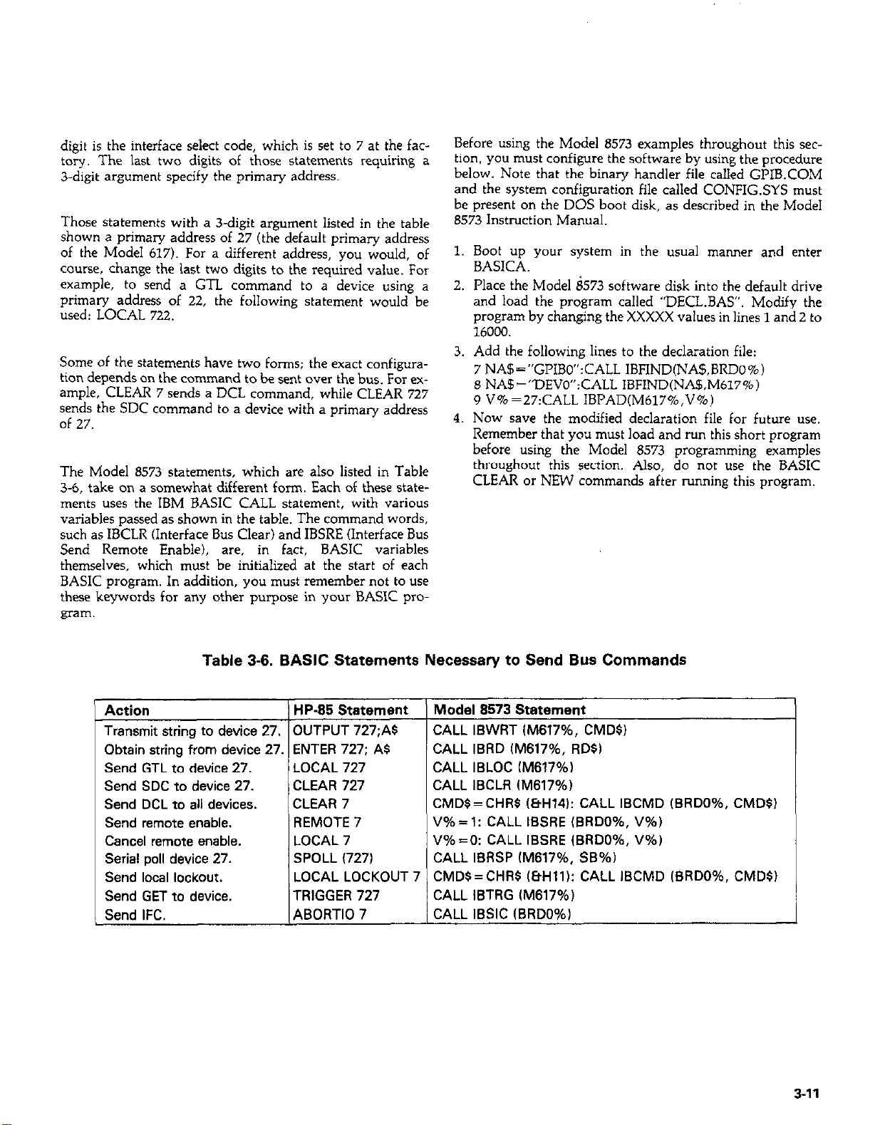
digit is the interface select code, which is set to 7 at the fac-
tory. The last two digits of those statements requiring a
3-d@ argument specify the primary address.
Those statements with a 3-digit argument listed in the table
shown a primary address of 27 (the default primary address
of the Model 617). For a different address, you would, of
course, change the last two digits to the required value. For
example, to send a GTL command to a device using a
primary address of 22, the following statement would be
used: LOCAL 722.
Some of the statements have two forms; the exact configura-
tion depends on the command to be sent over the bus. For example, CLEAR 7 sends a DCL command, while CLEAR 727
sends the SDC command to a device with a primary address
of 27.
The Model 8573 statements, which are also listed in Table
3-6, take on a somewhat different form. Each of these statements uses the IBM BASIC CALL statement, with various
variables passed as shown in the table. The command words,
such as IBCLR (Interface Bus Clear) and IBSRE (Interface Bus
Send Remote Enable), are, in fact, BASIC variables
themselves, which must be initialized at the start of each
BASIC program. In addition, you must remember not to use
these keywords for any other purpose in your BASIC program.
Before using the Model 8573 examples throughout this sec-
tion, you must configure the software by using the procedure
below. Note that the binary handler file called GPIB.COM
and the system configuration file called CONFIGSYS must
be present on the DOS boot disk, as described in the Model
8573 Instruction Manual.
1. Boot up your system in the usual manner and enter
BASICA.
2. Place the Model i573 software disk into the default drive
and load the program called “DECL.BAS”. Modify the
program by changing the XXXXX values in lines 1 and 2 to
16000.
3. Add the followine lines to the declaration file:
7 NA%=“GPIBO’:CALL IBFIND(NAS,BRDO%)
8 NA$=“DEVO”:CALL IBFIND(NA$,M617%)
9 V%=27:CALL IBPAD(M617%.V%)
4. Now save the modified declaration file for future use.
Remember that you must load and run this short program
before using the Model 8573 programming examples
throughout this section. Also, do not use the BASIC
CLEAR or NEW commands after running this program.
Table 3-6. BASIC Statements Necessary to Send Bus Commands
Action
HP-65 Statement
Transmit string to device 27. 1 OUTPUT 727;AS
Obtain string iom device 27. ENTER 727; AS
Send GTL to device 27.
Send SDC to device 27.
Send DCL to all devices.
Send remote enable.
Cancel remote enable.
Serial poll device 27.
Send local lockout.
Send GET to device.
Send IFC.
LOCAL 727
CLEAR 727
CLEAR 7
REMOTE 7
LOCAL 7
SPOLL (7271
LOCAL LOCKOUT 7
TRIGGER 727
ABORT10 7
Model 6573 Statement
CALL IBWRT IM617%, CMDS)
CALL IBRD lM617%, RDSI
CALL IBLOC lM617%)
CALL IBCLR lM617%)
CMDS=CHRS (EtH14): CALL IBCMD (BRDO%, CMDS)
V% = 1: CALL IBSRE (BRDO%, V%j
V%=O: CALL IBSRE lBRDO%, V%)
CALL IBRSP (M617%, SB%)
CMDS=CHRS (EtHll): CALL IBCMD (BRDO%, CMDS)
CALL IBTRG lM617%)
CALL IBSIC (BRDO%l
3-11
Page 66
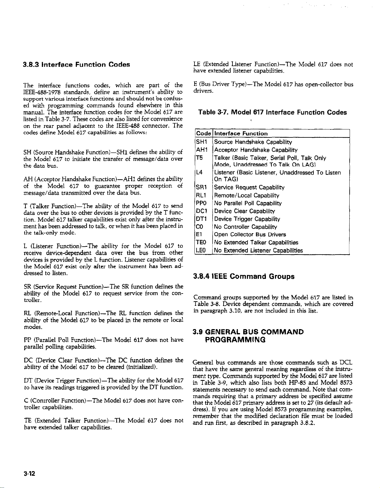
3.8.3 Interface Function Codes
LE (Extended Listener Function&The Model 617 does not
have extended listener capabilities.
The interface functions codes, which are part of the
IEEE-488-1978 standards, define an instrument’s ability to
support various interface functions and should not be confus-
ed with programming commands found elsewhere in this
manual. The interface function codes for the Model 637 are
listed in Table 3-7. These codes are also listed for convenience
on the rear panel adjacent to the IEEE-488 connector. The
codes define Model 617 capabilities as follows:
SH (Source Handshake Function)-SH1 defines the ability of
the Model 617 to initiate the transfer of message/data over
the data bus.
AH (Acceptor Handshake Function)-AH1 defines the ability
of the Model 617 to guarantee proper reception of
message/data transmitted over the data bus.
T (Talker Function)-The ability of the Model 617 to send
data over the bus to other devices is provided by the T func-
tion. Model 617 talker capabilities exist only after the instru-
ment has been addressed to talk, or when it has been placed in
the talk-only mode.
L (Listener Function&The ability for the Model 617 to
receive devicedependent data over the bus from other
devices is provided by the L function. Listener capabilities of
the Model 617 exist only after the instrument has been addressed to listen.
SR (Service Request Function)-The SR function defines the
ability of the Model 617 to request service from the controller.
RL (Remote-Local Function)-The RL function defines the
ability of the Model 617 to be placed in the remote or local
modes.
PI’ (Parallel Poll Function)-The Model 617 does not have
parallel polling capabilities.
E (Bus Driver Type)-The Model 617 has open-collector bus
drivers.
Table 3-7. Model 617 interface Function Codes
Code Interface Function
Stil Source Handshake Capability
AH1 Acceptor Handshake Capability
T5
Talker (Basic Talker, Serial Poll, Talk Only
Mode, Unaddressed To Talk On LAG)
L4
Listener (Basic Listener, Unaddressed To Listen
On TAG)
SRl Service Request Capability
RLl Remote/Local Capability
PPO No Parallel Poll Capability
DC1 Device Clear Capability
DTl Device Trigger Capability
co No Controller Capability
El
Open Collector Bus Drivers
TEO No Extended Talker Capabilities
LEO No Extended Listener Capabilities
3.8.4 IEEE Command Groups
Command groups supported by the Model 617 are listed in
Table 3-8. Device dependent commands, which are covered
in paragraph 3.10, are not included in this list.
3.9 GENERAL BUS COMMAND
PROGRAMMING
DC (Device Clear Function)-The DC function defines the
ability of the Model 617 to be cleared (initialized).
DT (Device Trigger Function)-The ability for the Model 617
to have its readings triggered is provided by theDT function.
C (Controller Function)-The Model 617 does not have controller capabilities.
TE (Extended Talker Function)-The Model 617 does not
have extended talker capabilities.
3-12
General bus commands are those commands such as DCL
that have the same general meaning regardless of the instru-
ment type. Commands supported by the Model 617 are listed
in Table 3-9. which also lists both HP-85 and Model 8573
statements necessary to send each command. Note that commands requiring that a primary address be specified assume
that the Model 617 primary address is set to 27 (its default address). If you are using Model 8573 programming examples,
remember that the modified declaration file must be loaded
and run first, as described in paragraph 3.8.2.
Page 67
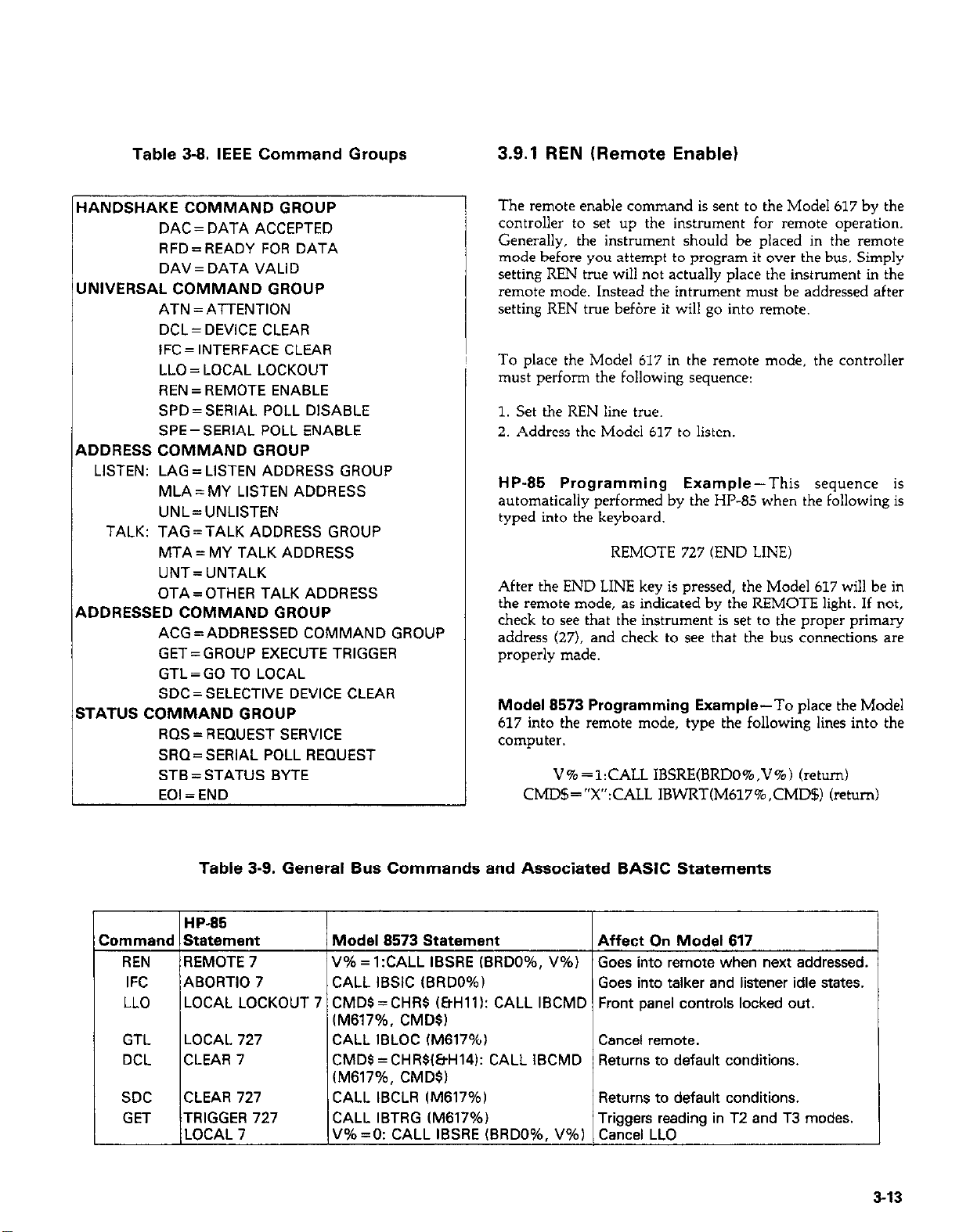
Table 3-8. IEEE Command Groups
3.9.1 REN (Remote Enable)
HANDSHAKE COMMAND GROUP
DAC= DATA ACCEPTED
RFD = READY FOR DATA
DAV = DATA VALID
UNIVERSAL COMMAND GROUP
ATN = ATTENTION
DCL = DEVICE CLEAR
IFC= INTERFACE CLEAR
LLO = LOCAL LOCKOUT
REN = REMOTE ENABLE
SPD = SERIAL POLL DISABLE
SPE=SERIAL POLL ENABLE
ADDRESS COMMAND GROUP
LISTEN: LAG = LISTEN ADDRESS GROUP
MLA = MY LISTEN ADDRESS
UNL=UNLISTEN
TALK: TAG=TALK ADDRESS GROUP
MTA = MY TALK ADDRESS
UNT= UNTALK
OTA = OTHER TALK ADDRESS
ADDRESSED COMMAND GROUP
ACG=ADDRESSED COMMAND GROUP
GET=GROUP EXECUTE TRIGGER
GTL = GO TO LOCAL
SDC = SELECTIVE DEVICE CLEAR
STATUS COMMAND GROUP
RQS=REQUEST SERVICE
SRQ=SERIAL POLL REQUEST
STB = STATUS BYTE
EOI = END
The remote enable command is sent to the Model 617 by the
controller to set up the instrument for remote operation.
Generally, the instrument should be placed in the remote
mode before you attempt to program it over the bus. Simply
setting REN true will not actually place the instrument in the
remote mode. Instead the intnxnent must be addressed after
setting REN true befbre it will go into remote.
To place the Model 617 in the remote mode, the controller
must perform the following sequence:
1. Set the REN line true.
2. Address the Model 617 to listen.
HP-85 Programming Example-This sequence is
automatically performed by the HP-85 when the following is
typed into the keyboard.
REMOTE 727 (END LINE)
After the END LINE key is pressed, the Model 617 will be in
the remote mode, as indicated by the REMOTE light. If not,
check to see that the instrument is set to the proper primary
address (27). and check to see that the bus connections are
properly made.
Model 8573 Programming Example-To place the Model
617 into the remote mode, type the following lines into the
computer.
V%=l:CALL IBSRE(BRDO%,V%) (return)
CMD$=“X”:CALL IBWRT(M617%,CMD$) (return)
Table 3-9. General Bus Commands and Associated BASIC Statements
HP-85
Command Statement
REN REMOTE 7
IFC ABORT10 7 CALL IBSIC (BRDO%)
LLO LOCAL LOCKOUT 7 CMDS=CHRS (EtHlll: CALL IBCMD Front panel controls locked out.
GTL LOCAL 727 CALL IBLOC fM617%)
DCL CLEAR 7 CMDS =CHRSl&H14): CALL IBCMD
SDC CLEAR 727 CALL IBCLR (M617%)
GET TRIGGER 727 CALL IBTRG (M617%)
LOCAL 7 V%=O: CALL IBSRE IBRDO%. V%l Cancel LLO
Model 8573 Statement Affect On Model 617
V% = l:CALL IBSRE (BRDO%, V%)
Goes into remote when next addressed.
Goes into talker and listener idle states.
(M617%. CMDS)
Cancel remote.
Returns to default conditions.
(M617%, CMDS)
Returns to default conditions.
Triggers reading in T2 and T3 modes.
3-13
Page 68
The instrument will go into the remote mode when the return
key is pressed the second time.
After the return key is pressed, the instrument will return to
the local and talker idle states.
3.9.2 IFC (Interface Clear)
The IFC command is sent by the controller to place the Model
617 in the local, talker and listener idle states. The unit will
respond to the IFC command by cancelling front panel TALK panel controls except POWER will be inoperative. REN must
or LISTEN lights. if the instrument was previously placed in
one of those modes.
To send the IFC command, the controller need only set the
IFC line true for a minimum of 100~sec.
HP-85 Programming Example-Before demonstrating the 2. Place the LLO command on the data bus
IFC command, turn on the TALK indicator with the following statements:
REMOTE 727 (END LINE)
ENTER 727;A$ (END LINE)
At this point, the REMOTE and TALK lights should be on.
The IFC command can be sent by typing in the following
statement into the HP-85: After the second statement is entered, the instrument’s front
ABORT10 7 (END LINE)
3.9.3 LLO (Local Lockout)
The LLO command is used to remove the instrument from the
local operating mode. After the unit receives LLO, all its front
be true for the instrument to respond to LLO. REN must be
set false to cancel LLO.
To send the LLO command, the controller must perform the
following steps:
1. Set ATN true.
HP-85 Programming Example-The LLO command is sent
by using the following HP-85 statement:
REMOTE 7 (END LINE)
LOCAL LOCKOUT 7 (END LINE)
panel controls will be locked out.
After the END LINE key is pressed, the REMOTE and TALK
lights will turn off, indicating that the instrument has gone into the talker idle state.
Model 8573 Proarammina Example-Place the instru-
ment in the remote-and talkeractive slates with the following
statements:
V% =l:CALL IBSRE(BRDO%,V%) (return)
CMD$=CHR$(&H5B):CALL IBCMD(BRDO%,CMD$)
bfum)
After the return key is pressed the second time, the instrument
should be in the remote and talker active states, as indicated
by the respective indicators.
To send IFC, enter the following statement into the IBM-PC:
CALL IBSIC(BRDO%) (return)
Model 8573 Programming Example-To send the LLO
command from the IBM-PC, type in the following statement:
V% =l: CALL IBSRE (BRDO%, V%) (RETURN)
CMD$=CHR$(&Hll):CALL IBCMD$(BRDO%,CMD$)
(return)
After the return key is pressed, Model 617 front panel con-
trols will be locked out.
3.9.4 GTL (Go To Local) and Local
The GTL command is used to take the instrument out of the
remote mode. With some instruments, GTL may also cancel
LLO. With the Model 617, however, REN must first be placed
false before LLO will be cancelled.
To send GTL, the controller must perform the following se-
quence.
3-14
Page 69
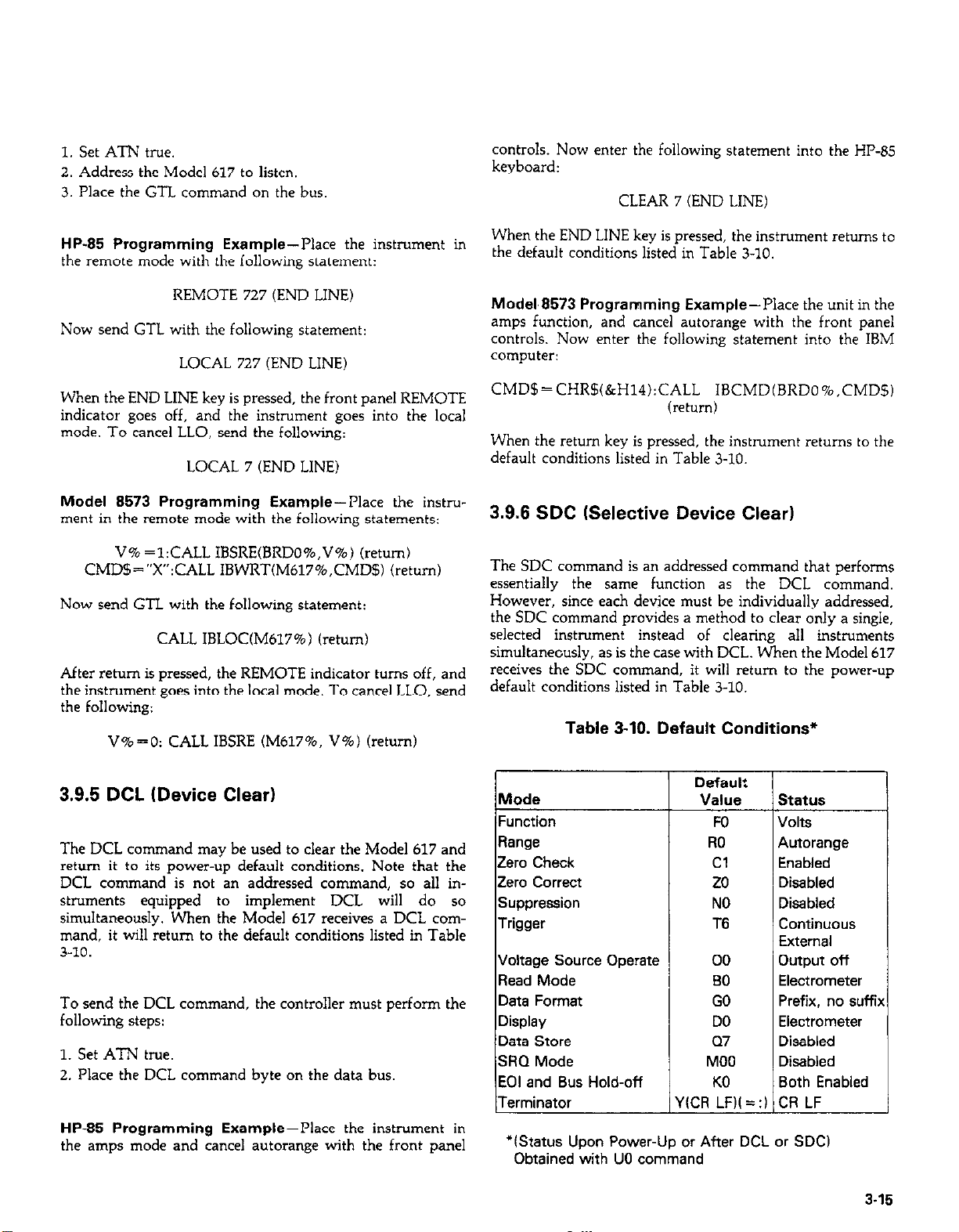
1. Set ATN true.
2. Address the Model 617 to listen.
3. Place the G-l-L command on the bus,
controls. Now enter the following statement into the HP-85
keyboard:
CLEAR 7 (END LINE)
HP-85 Programming Example--Place the instrument in
the remote mode with the following statement:
REMOTE 727 (END LINE)
Now send GTL with the following statement:
LOCAL 727 (END LINE)
When the END LINE key is pressed, the front panel REMOTE
indicator goes off, and the instrument goes into the local
mode. To cancel LLO, send the following:
LOCAL 7 (END LINE)
Model 8573 Programming Example--Place the instru-
ment in the remote mode with the following statements:
V%=l:CALL IBSRE(BRDO%,V%) (return)
CMD%=“X”:CALL IBWRT(M617%,CMD$) (return)
Now send GTL with the following statement:
CALL IBLOC(M617%) (return)
After return is pressed, the REMOTE indicator turns off, and
the instrument goes into the local mode. To cancel LLO, send
the following:
V%=O: CALL IBSRE (M617%, V%) (return)
When the END LINE key is pressed, the instrument returns to
the default conditions listed in Table 3-10.
Model,8573 Programming Example-Place the unit in the
amps function, and cancel autorange with the front panel
controls. Now enter the following statement into the IBM
computer:
CMD$=CHR$(&H14):CALL IBCMD(BRDO%.CMDS)
(return)
When the return key is pressed. the instrument returns to the
default conditions listed in Table 3-10.
3.9.6 SDC (Selective Device Clear)
The SDC command is an addressed command that performs
essentially the same function as the DCL command.
However, since each device must be individually addressed.
the SDC command provides a method to clear only a single,
selected instrument instead of clearing all instruments
simultaneously, as is the case with DCL. When the Model 617
receives the SDC command, it will return to the power-up
default conditions listed in Table 3-10.
Table 3-10. Default Conditions*
3.9.5 DCL (Device Clear)
The DCL command may be used to clear the Model 617 and
return it to its power-up default conditions. Note that the
DCL command is not an addressed command, so all instruments equipped to implement DCL will do so
simultaneously. When the Model 617 receives a DCL command, it will return to the default conditions listed in Table
3-10.
To send the DCL command, the controller must perform the
following steps:
1. Set ATN true.
2. Place the DCL command byte on the data bus
HP-85 Programming Example-Place the instrument in
the amps mode and cancel autorange with the front panel
Default /
Mode
Function
Range RO
Zero Check Cl
Zero correct 20
Suppression
Value
FO
NO
Trigger T6
Voltage Source operate
Read Mode
Data Format
Display
Data store
SKI Mode
EOI and Bus Hold-off
00
BO
GO
DO
Q7
MOO
KO
Prefix, no suffb
Terminator Y(CR LFN=:l CR LF
‘IStatus Upon Power-Up or After DCL or SDC)
Obtained with UO command
3.15
Page 70
To transmit the SDC command, the controller must perform
the following steps:
When the END LINE key is pressed, the instrument will process a single reading.
1. Set ATN true.
2. Address the Model 617 to listen.
3. Place the SDC command on the data bus.
HP-85 Programming Example-Using the front panel con-
trols, place the instrument in the amps mode and cancel
autorange. Enter the following statement into the HP-85:
CLEAR 727 (END LINE)
After END LINE is pressed, the instrument returns to the
power up default conditions listed in Table 3-10.
Model 8573 Programming Example-Place the instru-
ment in the amps function and cancel autorange with the
front panel controls. Now enter the following statement into
the IBM-PC:
CALL IBCLR(M617%) (return)
After the return key is pressed, the instrument returns to the
default conditions listed in Table 3-10.
3.9.7 GET (Group Execute Trigger)
Model 8573 Programming Example-Type in the follow-
ing statements to make sure the instrument is in the remote
and correct trigger modes for purposes of this demonstration:
V% =l:CALL IBSRE(BRDO%,V%) (return)
CMD$-‘T3X”:CALL IBWRT(M617%.CMD$)(retum)
Now send GET to the instrument with the following statement:
CALL IBTRG(M617%) (return)
When the return key is pressed, the instrument will process a
single reading.
3.9.8 Serial Polling (SPE,SPD)
The serial polling sequence is used to obtain the Model 617
status byte. The status byte contains important information
about internal functions, as described in paragraph 3.10.15.
Generally, the serial polling sequence is used by the controller
to determine which of several instruments has requested ser-
vice with the SRQ line. However, the serial polling sequence
may be performed at any time to obtain the status byte from
the Model 617.
GET may be be used to trigger the Model 617 to take readings
if the instrument is placed in the appropriate trigger mode
(more information on trigger modes may be found in paragraph 3.10.14).
To send GET, the controller must perform the following
steps:
1. Set ATN true.
2. Address the Model 617 to listen.
3. Place the GET command byte on the data bus.
HP-85 Programming Example-Type in the following
statements into the HP-85 keyboard to place the instrument
in remote and enable the correct trigger mode for this
demonstration:
REMOTE 727 (END LINE)
OUTPUT 727: ‘T3X” (END LINE)
Now send the GET command with the following statement:
TRIGGER 727 (END LINE)
The serial polling sequence is conducted as follows:
1. The controller sets ATN true.
2. The controller then places the WE (Serial Poll Enable)
command byte on the data bus. At this point, all active
devices are in the serial poll mode and waiting to be ad-
dressed.
3. The Model 617 is then addressed to talk.
4. The controller sets ATN false.
5. The instrument then places its status byte on the data bus.
at which point it is read by the controller.
6. The controller then sets ATN true and places the SPD
(Serial Poll Disable) command byte on the data bus to end
the serial polling sequence.
Once instruments are in the serial poll mode, steps 3 through
5 above can be repeated by sending the correct talk address
for each instrument. ATN must be true when the address is
transmitted and false when the status byte is read.
HP-85 Programming Example-The HP-85 SPOLL state-
ment automatically performs the sequence just described. To
demonstrate serial polling, type in the following statements
into the HP-85
3-16
Page 71
REMOTE 727 (END LINE)
S = SI’OLL(727) (END LINE)
DISP S (END LINE)
When the END LINE key is pressed the second time, the computer conducts the serial polling sequence. The decimal value
of the status byte is then displayed on the computer CRT
when the END LINE key is pressed the third time. More information on the status byte may be found in paragraph 3.10.15.
Model 8573 Programming Example-Use the following
sequence to serial poll the instrument and display the decimal
value of the status byte on the computer CRT:
V%=l:CALL IBSRE(BRDO%,V%) (return)
CALL IBRSP(M617%,SB%) (return)
PRINT SB% (return)
When the return key is pressed the second time, the serial
polling sequence is conducted. The status byte value is
displayed when the return key is pressed the third time.
3.10 DEVICE-DEPENDENT COMMAND
PROGRAMMING
IEEE-488 device-dependent commands are used with the
Model 617 to control various operating modes such as function, range, trigger mode, and data format. Each command is
made up of a single ASCII letter followed by a number
representing an option of that command. For example, a
command to control the measuring function (Volts, Ohms,
Amps, Coul) is programmed by sending an ASCII “F” followed by a number representing the function option. The
IEEE-488 bus actually treats these commands as data in that
ATN is false when the commands are transmitted.
A number of commands may be grouped together in one str-
ing. A command string is usually terminated with an ASCII
“X” character, which tells the instrument to execute the cornmand string. Commands sent without the execute character
will not be executed at that time, but they will be retained
within an internal command buffer for execution at the time
the X character is received. If any errors occur, the instrument
will display appropriate front panel error messages and
generate an SRQ if programmed to do so.
Function (F); Range (R); Zero Check (C); Zero Correct (Z);
Suppress (N); Trigger(T); Voltage Source Operate (0): Read
Mode (B); Display Mode (D): Data Storage (Q): SRQ Mode
CM): EOI and Bus Hold-off (K); and Terminator (Y). Thus to
force a particular command sequence, you would follow each
command with the execute character, as in the example string, ClXZlXCOX, which can be used to zero correct the instrument.
These programming aspects are covered at the end of this
paragraph.
Device-dependent commands can be sent either one at a time,
or in groups of several commands within a single string.
Some examples of valid command strings include:
FOX Single command string.
FOKlDOROX Multiple command string.
T6 X Spaces are ignored.
Typical invalid command strings include:
HlX Invalid command, as H is not one of the instrument
commands.
F9X Invalid command option because 9 is not an option of
the F command.
If an illegal command (IDDC), illegal command option UDD-
CO), is sent, or if a command string is sent with REN false,
the string will be ignored.
Devicedependent commands that control the Model 617 are
listed in Table 3-11. These commands are covered in detail in
the following paragraphs. The associated programming ex-
amples show how to send the commands with both the HP-85
and the IBM-IW8573.
NOTE
Programming examples assume that the Model
617 is at its factory default value of 27.
In order to send a devicedependent command, the controller
must perform the following steps:
Commands that affect the electrometer section (F, R, C, Z, N,
T, and A) will trigger a reading when the command is executed. These bus commands affect the Model 617 much like
the front panel controls. Note that commands are not
necessarily executed in the order received; instead, they will
be executed in the same order as they appear in the status
word:
1. Set ATN true.
2. Address the Model 617 to listen.
3. Set ATN false.
4. Send the command string cwer the bus one byte at a time.
317
Page 72
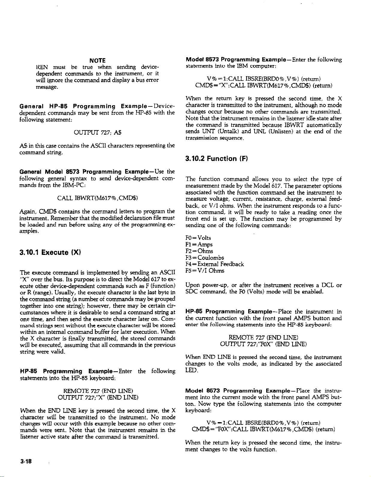
NOTE
REN must be true when sending devicedependent commands to the instrument, or it
will ignore the command and display a bus error
message.
General HP-85 Programming Example-DDevice-
dependent commands may be sent from the HP-65 with the
following statement:
oul-PuT 727; A5
A$ in this case contains the ASCII characters representing the
command string.
General Model 8573 Programming Example-Use the
following general syntax to send device-dependent commands from the IBM-PC:
CALL IBWRT(M617%,CMD5)
Again, CMD$ contains the command letters to program the
instrument. Remember that the modified declaration file must
be loaded and run before using any of the programming examples.
3.10.1 Execute (Xl
The execute command is implemented by sending an ASCII
“X” over the bus. Its purpose is to direct the Model 617 to ex-
ecute other device-dependent commands such as F (function)
or R (range). Usually, the execute character is the last byte in
the command string (a number of commands may be grouped
together into one string); however, there may be certain circumstances where it is desirable to send a command string at
one time, and then send the execute character later on. Command strings sent without the execute character will be stored
within an internal command buffer for later execution. When
the X character is finally transmitted, the stored commands
will be executed, assuming that all commands in the previous
string were valid.
HP-85 Programming Example-Enter the following
statements into the HP-85 keyboard:
Modal 8573 Programming Example-Enter the following
statements into the IBM computer:
V%=l:CALL IBSRE(BRDO%,V%) (return)
CMD$=“X”:CALL IBWRT(M617%,CMD$) (return)
When the retmn key is pressed the second time, the X
character is transmitted to the instrument, although no mode
changes occur because no other commands are transmitted.
Note that the instrument remains in the listener idle state after
the command is transmitted because IBWRT automatically
sends UNT (Untalk) and UNL (Unlisten) at the end of the
transmission sequence.
3.10.2 Function IF)
The function command allows you to select the type of
measurement made by the Model 617. The parameter options
associated with the function command set the instrument to
measure voltage, current, resistance, charge, external feedback, or V/I ohms. When the instrument responds to a function command, it will be ready to take a reading once the
front end is set up. The function may be programmed by
sending one of the following commands:
FO=Volts
Fl = Amps
F2 = Ohms
F3 = Coulombs
F4=Extemal Feedback
F5=V/I Ohms
Upon power-up, or after the instrument receives a DCL or
SDC command, the FO (Volts) mode will be enabled.
HP-85 Programming Example-Place the instrument in
the current function with the front panel AMPS button and
enter the following statements into the HP-85 keyboard:
REMOTE 727 (END LINE)
OUTPUT 727;“FOX” (END LINE)
When END LINE is pressed the second time, the instrument
changes to the volts mode, as indicated by the associated
LED.
REMOTE 727 (END LINE)
OUTPUT 727;“X” (END LINE)
When the END LINE key is pressed the second time, the X
character will be transmitted to the instrument. No mode
changes will occur with this example because no other commands were sent. Note that the instrument remains in the
listener active state after the command is transmitted.
3-18
Model 8573 Programming Example--Place the instru-
ment into the current mode with the front panel AMPS button. Now type the following statements into the computer
keyboard:
V% =l:CALL lBSRE(BRDO%,V%) (return)
CMD$=“FOX”:CALL IBWRT(M617% ,CMD$) (return)
When the return key is pressed the second time, the instrument changes to the volts function.
Page 73
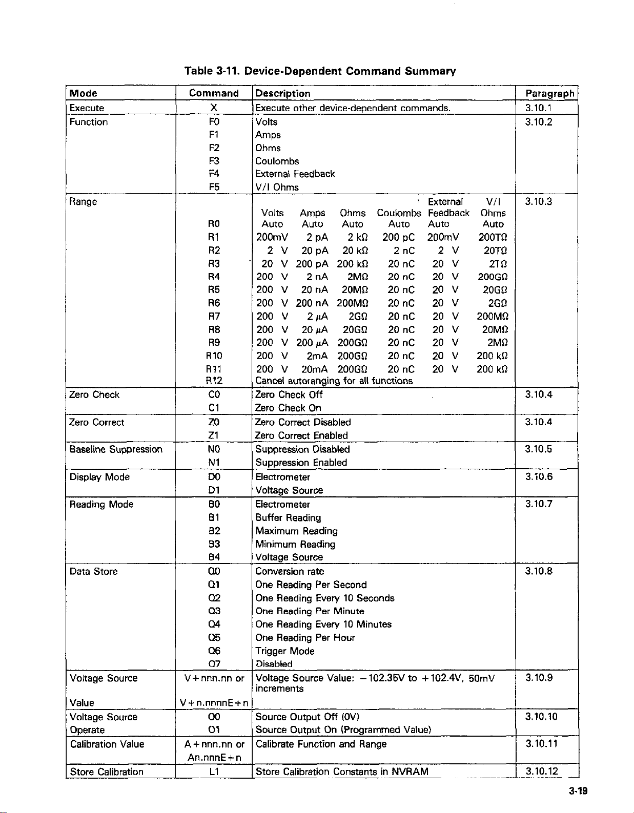
-
/lode
xecute
:unction
lange
:ero Check
:ero correct
laseline Suppression
display Mode
leading Mode
)ata Store
loltage Source
falue
roltage Source
)perate
Calibration Value
: .^.^ P”l:b.-^ri^^
Table 3-11. Device-Dependent Command Summary
Command
X Execute other device-dependent commands.
Description
FO Volts
Fl
Amps
F2 Ohms
F3 Coulombs
F4
External Feedback
F5 V/I Ohms
: External V/I
Volts Amps Ohms Coulombs Feedback Ohms
RO Auto
Rl 200mV
R2
2 V 20 pA 20 kR 2nC 2V 20Tfl
R3 20 V 200 pA 200 k0
R4
200 v
Auto Auto Auto Auto
2 PA
2 kR 2OOpC 200mV 2OOTQ
20 nc 20 v 2TR
2 nA 2MQ 20 nC 20 v
200GLl
R5 200 V 20 nA 20M0 20 nC 20 v
R6 200 V 200 nA 200MQ
R7
R6
R9
200 V 2 /LA 2GO
200 V 20/~A 20GS2
200 V 200 PA 200G0
RlO 200 v 2mA 200GSI
Rll 200 V 20mA 200GQ
20 nC 20 v 2G0
20 nC 20 v
200MR
20 nC 20 v
20 nC 20 v
20 nC
20 nC
20 v
20 v
200 kR
200 kQ
R12 Cancel autoranging for all functions
co
Cl
Zero Check Off
Zero Check On
zo Zero Correct Disabled
Zl Zero Correct Enabled
NO Suppression Disabled
Nl Suppression Enabled
DO Electrometer
Dl
Voltage Source
BO Electrometer
El
82
Buffer Reading
Maximum Reading
83 Minimum Reading
84
Voltage Source
00 Conversion rate
01
One Reading Per Second
a2 One Reading Every 10 Seconds
Q3 One Reading Per Minute
Q4 One Reading Every 10 Minutes
Q5
One Reading Per Hour
Q6 Trigger Mode
Q7 Disabled
V+ nnn.nn or Voltage Source Value: - 102.35V to + 102.4V, 50mV
increments
V+n.nnnnE+n
00 Source Output Dff (OV)
01 Source Output On (Programmed Value)
A+ nnn.nn or Calibrate Function and Range
An.nnnE+n
I4 Ph.-,. P”liL.....i.... P^..^.^^.^ i.. hl\,D Ah”
Paragrapl
3.10.1
3.102
3.10.3
Auto
20G$l
20MR
2MR
3.10.4
3.10.4
3.10.5
3.10.6
3.10.7
3.10.8
3.10.9
3.10.10
3.10.11
2 ‘1n ‘I?
3-19
Page 74

Table 3-11. Device-Dependent Command Summary (Cont.)
Mode
3ata Format
Trigger Mode
SRQ
EOI and Bus Hold Off
Terminator
Status Word
-r-
,
Command
M2
Ml6
M32
YfLF CR)
YICR LF)
YIASCII)
GO
Gl
G2
TO
Tl
M
T3
T4
15
T6
T7
MO
Ml
M8
KO
Kl
K2
K3
YX
IJO
Ul
u2
Description
Reading with Prefix (NDCV - 1.23456E+OO)
Reading without Prefix f - 1.23456E+OO)
Reading with Prefix and Buffer Suffix (if in Bl)
(NDCV-1.23456E+OO, 012)
Continuous, Trigger by Talk
One-Shot, Trigger by Talk
Continuous, Trigger by GET
One-Shot. Trigger by GET
Continuous, Trigger by X
One-Shot, Trigger by X
Continuous, Trigger by External Trigger
One-Shot, Trigger by External Trigger
Disable SRQ
Reading Overflow
Buffer Full
Reading Done
Ready
Error
Enable EOI and Bus Hold-off On X
Disable EOI, Enable Bus Hold-off On X
Enable EOI, Disable Bus Hold-off On X
Disable both EOI and Bus Hold-off On X
Terminator = LF CR
Terminator = CR LF
Terminator = ASCII Character
No Terminator
Send Status Format: 617 FRRCZNTOBGDQMMKYY
Error Conditions
Data Conditions
Paragraph
3.10.13
3.10.14
3.10.15
3.10.16
3.10.17
3.10.18
3.10.3 Range (RI
The range command gives the user control over the sensitivi-
ty of the instrument. This command, and its options, perform
essentially the same functions as the front panel AUTO and
up and down range buttons. Range command parameters and
the respective ranges for each measuring function are summarized in Table 3-12. The instrument will be ready to take a
reading after the range is set up when responding to a range
command.
Upon power up, or after receiving a DCL or SDC command,
the instrument will be in the RO (autorange) mode.
3-20
HP-85 Programming Example-Make sure the instrument
is in the autorange mode and then enter the following
statements into the HP-85:
REMOTE 727 (END LINE)
OUTPLJT 727;“R3X” (END LINE)
When the END LINE key is pressed the second time, the in-
strument cancels the autorange mode, and enters the R3 range
instead.
Model 8573 Programming Example-Make sure the in-
strument is in the autorange mode. Now enter the following
statements into the IBM-PC keyboard:
Page 75
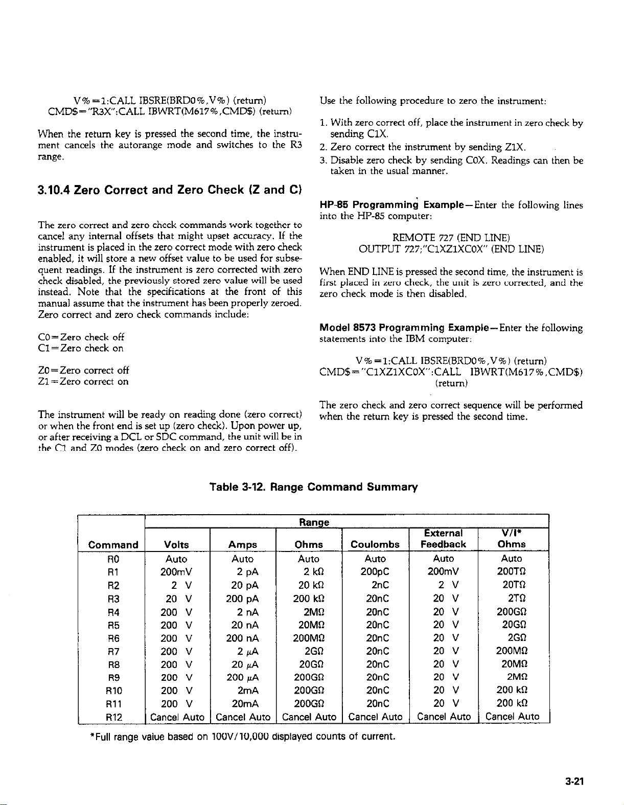
V% =l:CALL IBSRE(BRDO%.V%) (return)
CMD$=“R3X”:CALL IBWRT(M617%,CMD5) (return)
When the return key is pressed the second time, the instru-
ment cancels the autorange mode and switches to the R3
Et”ge.
3.10.4 Zero Correct and Zero Check (2 and C)
The zero correct and zero check commands work together to
cancel any internal offsets that might upset accuracy. If the
instrument is placed in the zero correct mode with zero check
enabled, it will store a new offset value to be used for subsequent readings. If the instrument is zero corrected with zero
check disabled, the previously stored zero value will be used
instead, Note that the specifications at the front of this
manual assume that the instrument has been properly zeroed.
Zero correct and zero check commands include:
CO = Zero check off
Cl = Zero check on
ZO=Zero correct off
Zl = zero correct on
Use the following procedure to zero the instrument:
1. With zero correct off, place the instrument in zero check by
sending ClX.
2. Zero correct the instrument by sending ZlX.
3. Disable zero check by sending COX. Readings can then be
taken in the usual manner.
HP-85 Programming Example-Enter the following lines
into the HP-85 computer:
REMOTE 727 (END LINE)
OUTPUT 727;“ClXZlXCOX” (END LINE)
When END LINE is pressed the second time, the instrument is
first placed in zero check, the unit is zero corrected, and the
zero check mode is then disabled.
Model 8573 Programming Example-Enter the following
statements into the IBM computer:
V% =l:CALL IBSRE(BRDO%,V%) (return)
CMD$=“ClXZlXCOX”:CALL IBWRT(M617%,CMD$)
(return)
The instrument will be ready on reading done (zero correct)
or when the front end is set up (zero check). Upon power up,
or after receiving a DCL or SDC command, the unit will be in
the Cl and ZO modes (zero check on and zero correct off).
Table 3-12. Range Command Summary
T-
r
Command
RO
Rl
R2
R3
R4
R5
R6
R7
R8
R9
RlO
Rll
R12
Volts
Auto
200mV
2 v
20 v
200 v
200 v
200 v
200 v
200 v
200 v
200 v
200 v
:ancel Auto
Amps
Auto
2 PA
20 pA
200 pA
2 nA
20 nA
200 nA
2 PA
20 fi
200 pA
2mA
20mA
Cancel Auto
Cancel Auto
The zero check and zero correct sequence will be performed
when the return key is pressed the second time.
Range
Ohms
Auto
2 kG
20 kC
200 kR
2MC
20MR
200MC
2GR
20GR
200GQ
200GO
200GO
-
Coulombs
Auto
2oopc
2nC
20nC
20nC
20nC
20nC
20nC
20nC
20nC
20nC
20nC
Cancel Auto
T
External
Feedback
Auto
200mV
2v
20 v
20 v
20 v
20 v
20 v
20 v
20 v
20 v
20 v
Cancel Auto
V/I’
Ohms
Auto
200Tt-l
20TR
2TC
200GR
20GQ
2GC
200MR
20Mt-l
2Mtl
200 kR
200 kR
Cancel Auto
1
*Full range value based on 100V/10,000 displayed counts of current.
3-21
Page 76

3.10.5 Baseline Suppression (N)
HP45 Programming Example-To enable baseline sup-
pression, type in the following lines:
The baseline suppression mode allows a stored offset value to
be subtracted from subsequent readings. When the suppression mode is enabled with the appropriate command, the in-
strument will internally store the baseline value with the next
triaered conversion. All subsequent readings will be the dif-
f&&e between the stored b&line value and the actual
signal level. For example, if 1OOmV is stored as a baseline,
that value will be subtracted from the following readings. See
paragraph 2.11.2 for a complete description.
To use baseline suppression, perform the following steps:
1. Cancel baseline suppression by sending NOX if already
enabled.
2. Select a range and function consistent with the expected
measurement,
3. Connect the signal to be used as a baseline to the instrument input.
WllmuIuc
..-..I....U
The voltage present on the input terminals
may be larger than the displayed value. For
example, if a 150VDC baseline is stored. an
applied voltage of +175V will result in a
displayed reading of only +25V
REMOTE 727 (END LINE)
CXJTl’UT 727;“Nlx” (END LINE)
When the END LINE key is pressed the second time, the
baseline suppression mode is enabled.
Model 8573 Programming Example-Type the following
commands into the HP-85 keyboard in order to enable
baseline suppression:
V% =l:CALL IBSRE(BRDO%,V%) (return)
CMD$=“NlX”:CALL IBWRT(M617%,CMD$) (return)
The baseline suppression mode will be enabled when the
return key is pressed the second time.
3.10.5 Display Mode IDI
The two parameters associated with the display mode com-
mand control whether the front panel display shows the elec- ?r the front panel display shows the elec-
trometer reading or the voltage source value. Thus, this com- lmg or the voltage source value. Thus, this command performs essentially the same function as the front ms essentially the same function as the front
panel DISPLAY button. The two display command .AY button. The two display command
parameters are:
4. Enable baseline suppression by sending NlX over the bus.
The baseline will be stored when the command is executed.
5. Disconnect the baseline signal from the instrument and
connect the signal to be measured in its place. Subsequent
readings will be the difference between the baseline and the
applied signal.
NOTES:
1. Baseline suppression reduces the dynamic range of the
measurement. For example, if the stored baseline value is
1oOmV on the 200mV range, an input voltage of 1COmV or
more would overrange the instrument even though
voltages up to 199.99mV are normally within the
capabilities of the 2oOmV range. If the instrument is in the
autorange mode, it will move up range if necessary.
2. Setting the range lower than the stored baseline value will
overrange the instrument.
3. Accurate control over when the baseline is actually stored
may be achieved by placing the instrument in a one shot
trigger mode. Once the desired baseline value is connected
to the instrument, the baseline can be stored by sending
NIX.
4. Function changes cancel baseline suppress. Refer to paragraph 2.11.2 for details concerning suppress.
DO=Electrometer
Dl = Voltage source
Upon power up, or after receiving a DCL or SDC command,
the instrument will be in the DO (electrometer) mode.
NOTE
When in the Dl mode, sending an electrometer
command (F, R, C, Z, N, or T) will cause the
instrument to revert to the DO (electrometer)
mode.
To program the desired display mode over the bus, you need
only send the appropriate command string. For example,
DlX would be transmitted to view the voltage source value
on the display.
HP-85 Programming Example-Using the front panel
DISPLAY button place the display in the electrometer mode.
Now type in the following lines:
REMOTE 727 (END LINE)
OUTPUT 727;“DlX” (END LINE)
3-22
Page 77

When the END LINE key is pressed the second time, the
display shows the voltage source value.
Model 8573 Programming Example-Momentarily power
down the instrument and then enter the following lines into
the IBM computer:
V% =l:CALL IBSRE(BRDO%,V%) (return)
CMD$=“DlX”:CALL IBWRT(M617%,CMD$) (return)
Note that the instrument changes from the electrometer
dispiay mode to the voltage source display mode when the
return key is pressed the second time.
3.10.7 Reading Mode (B)
The reading mode command parameters allow the selection
of the source of data that is transmitted over the IEEE-488
bus. Through this command, you have a choice of data from
the electrometer, voltage source, data store reading, or
minimum and maximum values. Note that the commands
associated with data store are always available; however the
suffix of the reading string will show Ooo if data store is
disabled, as in NDCV +12345E+CO,000. Minimum/maximum values returned will be the last values stored, unless
these parameters are requested after a DCL, in which case
unuseable readings will be returned.
sending the B2 or B3 commands. Note that the maximum and
minimum values are updated at the maximum reading rate
while data store is enabled. See paragraph 3.10.8 for a complete description of data storage.
The voltage source value is returned in a similar manner bv
sending B4X. Once the desired reading mode has been
selected, the data string can be read by addressing the instru-
ment to talk and reading the bvtes in the strinrt in the normal
manner.
HP-85 Programming Example-Use the following se-
quence to read the voltage source value and display it on the
computer CRT:
OUTPUT 727;“B4X” (END LINE)
ENTER 727; A$ (END LINE)
The second command above changes the reading mode to access the voltage source, while the third and fourth statements
acquire the reading and display it on the CRT.
Model 8573 Programming Example-To display the
voltage source value on the computer CRT, enter the follow-
ing program statements into the IBM computer:
_
REMOTE 727 (END LINE)
DISP A$ (END LINE)
Parameters associated with the reading mode include:
BO=Electrometer
Bl=Data store reading
B2=Maximum reading
B3 = Minimum reading
B4=Voltage source value.
Upon power up, or after receiving a DCL or SDC command,
the unit will be in the BO (electrometer) mode.
When in BO, normal electrometer readings will be sent. In a
continuous trigger mode, readings will be updated at the conversion rate (one reading every 36Omsec. In Bl, readings will
be taken from consecutive data store locations, beginning
with the oldest reading and progressing to the newest reading
until all readings currently stored have been read. Once all
readings have been requested, the unit will cycle back and
begin again. These readings may be accessed even if data
store is still taking place.
While data store is enabled, the maximum (most positive) and
minimum (most negative) readings may also be requested by
V% =l:CALL IBSRE(BRDO%,V%) (return)
CMD$=“B4X”:CALL IBWRT(M617%,CMD$) (return)
RD$=SPACE!§Q5):CALL IBRD(M617%,RD$) (return)
PRINT RD$ (return)
The second statement above programs the reading mode to
access the voltage source value. The third statement addresses
the instrument to talk and reads the data string from the instrument, while the fourth statement mints the data strine on
the computer CRT.
3.10.8 Data Store Mode
The data store commands enter the data storage mode and
allow you to store up to 100 readings with internal memory
of the Model 617. By entering an appropriate parameter,
readings may be stored at one of six intervals between the
conversion rate and one reading per hour. Either during or
after the storage process, readings, including maximum and
minimum values, may be recalled by using the B command as
described in the last paragraph.
Once the unit has logged all 100 readings, the instrument will
stop data storage until another Q command is sent to enable
3-23
Page 78

data store cmce again. Note that the instrument may be programmed to generate an SRQ when memory is full, as
described in paragraph 3.10.15.
The available storage intervals include:
QO= Conversion rate (one reading every 360msec)
Ql =One reading per second
Q2 = One reading every 10 seconds
Q3 = One reading per minute
Q4 =One reading every 10 minutes
QS = One reading per hour.
Q6=Trigger mode (TRIG button)
Q’I=Data store disabled
In addition to the various rates, data store can be used at a
rate determined by the TRIG button (Q6 mode). When in
this mode, one reading will be stored in memory each time
TRIG button is operated.
Upon power up, or after a DCL or SDC command. the
data
store will be disabled (Q7 mode.)
NOTES:
1. To use data store on a one-shot basis with other trigger
stimuli. ulace the instrument in the 00 mode and select
the desired one-shot trigger mode (paragraph 3.10.14).
2. In Qo and Ql, the storage rate may be decreased if the instrument is in autorange and a range change occurs.
HP-85 Programming Example-Enter the program below
to enable data store operation and obtain and display 100
readings on the computer CRT:
PROGRAM COMMENTS
10 DIM A$ [ZS]
20 REMOTE 727 Send remote enable
30 OUll’UT 727;“QOX” Enable data store at
conversion rate.
40 S = SPOLL(727)
Serial poll the 617.
50 IF NOT BIT(S.1) THEN 40 If not full, wait.
60 OUTPUT 727;“BlG2X” Set read mode to data
store.
70 FORI = 1TO100 Loop 100 times.
80 ENTER 727:A$
90 DISP AS
100 NEXT I
Get a reading.
Display it.
Loop back and get next
readine.
fill (lines 40 and 501, turn on the data store output (line 60).
and then request and display all loo readings(lines 70-100).
Model 8573 Programming Example-To demonstrate
data store operation, load the modified DECL.BAS file and
enter the program lines below:
PROGRAM
10 NA$=“GPIBO”:CALL IBFIND
(NA$,BRDO%)
20 NA$=“DEVO”:CALL IBFIND
(NA$,MblZ$
30 V% =27:CALL IBPAD
(M617%.V%)
40 V%=l:tiALi IBSRE
COMMENTS
Find the board
descriptor.
Find the instrument
descriptor.
Set primary address
to 27.
Send remote enable.
(BRDO%,V%)
50 CMD$=“QOX”:CALL IBWRT
(M617%,CMD$)
60 CALL IBRSP(M617%,SB%)
70 IF (SB% AND 2) = 0 THEN
Enable data store at
conversion rate.
Get status byte.
If not full, wait.
60
80 CMD$=“BlGZX”:CALL
Turn on data store.
IBWRT(M617%,CMD$)
90 FORI = 1TOlOO
100 RD$=SPACE$(25):CALL
Loop 100 times.
Get a reading.
IBRD(M617%,RD$)
110 PRINT RD$
120 NEXT I
Display the reading.
Go back and get
another.
130 V % = 0:CALL IBONL
Close the board file.
(BRDO%,V%)
140 CALL IBONL(M617%,V%)
Close the instrument
.~.
Press the IBM F2 key to run the program. Data store is enabled (line 50). the program waits for memory to fill (lines 60
and 70), the output is turned on (line 80), and all 100
readings are then requested and displayed (lines 90-120).
3.10.9 Voltage Source Value (VI
The voltage source value command allows you to program
the built-in voltage source of the Model 617 to between
- 102.35V and + 102.4V in 50mV increments. Normally, the
voltage source output is updated at the beginning of each
electrometer conversion (every 160msec); however, you can
force an immediate update by applying an appropriate trigger
stimulus to force the start of a new conversion (see paragraph
3.10.14 for more information on triggering).
After entering the program, press the HP-85 RUN key. The
program will enable data store (line 30), wait for memory to
3-24
The voltage swrce value is programmed by sending the V
Page 79

command letter followed by a maximum of 5% digits representing the voltage value. The unit will round off the programmed values to 5OmV minimum increments. Either nor-
mal or scientific representation may be used as indicated
below:
Vnmum (normal convention)
Vn.nnnnE+n (scientific notation)
Upon power up or after a DCL or SDC, the source output
will be programmed to oO.oOV.
Some equivalent examples of these two conventions are
shown below:
N0IlIlal Scientific
V25
v99.1
vo.05
v-11
V2SEfl
V0.99E+2
V50E-3
V-1X2+1
Note that merely programming the swrce value does not ap-
ply the voltage to the voltage source ourput terminals. The
output must be separately programmed on or off as described
in the following paragraph.
3.10.10 Voltage Source Operate (0)
The voltage source operate command performs essentially the
same operations as the front panel OPERATE button. The
parameters included with this command are:
Oo=Source output off (Output =OV)
Ol=Source output w-, (Output = programmed value)
Upon power up, or after receiving a DCL or SDC command,
the instrument will be in the 00 (Source off) mode.
Keep in mind that the voltage swrce has a maximum current
output of 2mA: the OPERATE LED will flash if this value is
exceeded.
WARNING
Hazardous voltage may be present on the
voltage source terminals, depending on the
programmed value.
HP-85 Programming Example-Enter the following state-
ments into the HP-85 to program and display the swrce and
turn the output on:
HP-85 Programming Example-To program the voltage
saxce to a value of -loV, press the front panel DISPLAY
button to view the source value and enter the following state-
ments into the computer:
REMOTE 727 (END LINE)
OUTPUT 727;‘DlV-10X” (END LINE)
When the second slakment is executed, the source value is
programmed for a value of -lOV.
Model 8573 Programming Example-Momentarily power
down the instrument and then select the voltage source with
the front panel DISPLAY button. Now enter the following
statements into the IBM computer:
V% =l:CALL IBSRE (BRDO%,V%) (return)
CMD$=“DlV-lOX”:CALL IBWRT(M617%, CMD$)
baml)
The voltage scwrce will be programmed to a value of -1OV
when the second statement is executed.
REMOTE 727 (END LINE)
OIJTRJT 727:“DlV6Olx” (END LINE)
When the command string is sent Lo the instrument, the display mode is changed to view the source value, the source
voltage is programmed to +6V, and the source output is
turned on.
Model 8573 Programming Example-Enter the following
statements into the IBM computer:
V% =l:CALL IBSRE(BRDO%,V%) (return)
CMD$=“DlV601X”:CALL lBWRT(M617%,CMD$)
(return)
When the command string is sent to the instrument, the display will change to the source mode, the scurce value will be
programmed to a value of +6V, and the source output wilI
be turned on.
3.10.11 Calibration Value (A)
One advanced feature of the Model 617 is its digital calibra-
tion capabilities. Instead of the mire difficult method of ad-
3-25
Page 80
justing a number of potentiometers, the user need only apply
an appropriate calibration signal and send the calibration
value over the bus. The calibration command may take on
either of the following forms:
Ann.nnn
An.nnnnE+n
Thus, the following two commands would be equivalent:
Al9
A1.9E+l
In this example, the nominal value for the 20V range is being
used. Note that only as many significant digits as necessary
need be sent. In this case, the exact calibration point is assumed to be 19.000 even though only the first two digits were
actually sent.
If the calibration value is outside the allowed range (? 6% of
nominal value), a number error will occur, as indicated by
the following message:
n Err
The calibration value is sent to the instrument when the
second statement is executed.
3.10.12 Non-Volatile Memory Storage IL)
The Model 617 uses non-volatile (NV) RAM to store calibra-
tion parameters. Once the instrument has been calibrated, as
described in the last p&graph, the NVRAM storage command should be sent to permanently store these parameters.
This procedure is performed by sending the following sequence: LlX. NVRAM storage will take place when the instrument receives this command over the bus. Note that
NVRAM storage may be disabled by changing the position of
a calibration jumper, as described in Section 7. If the jumper
is in the enabled position, all calibration must be properly
done, or calibration of all functions and ranges will be affected.
NOTE
Do not perform the following programming exam&s unless actual NVRAM storaee is desired.
Uniess proper calibrating para&te;s have~been
previously programmed, inadvertent use of this
command could affect instrument accuracy.
Once all functions and ranges have been calibrated, permanent storage of calibration parameters must be performed, as
described in paragraph 3.10.12.
NOTE
The proper calibration signal must be connected
to the instrument before attempting calibration.
See Section 7 for complete details on calibrating
the instrument either from the front panel or
over the bus.
HP85 Programming Example-The following statements
can be used to calibrate the instrument on the 2oOV range:
REMOTE 727 (END LINE)
OUTPUT 727;“A190X” (END LINE)
When the second statement is executed, calibration of the
2OOV range is performed, assuming that the correct calibra-
tion value is applied to the instrument.
Model 8573 Programming Example-Use the following
statements to send the 2COV range calibration value to the in-
strument:
V%=l:CALL IBSRE(BRDO%,V%) (return)
CMD$=“AlQOX”:CALL IBWRT(M617%,CMD$) (return)
HP-85 Programming Example-Use the following
statements to perform NVRAM storage:
REMOTE 727 (END LINE)
OUTPUT 727;“LlX” (END LINE)
NVRAM storage will be performed when the second statement is executed.
Model 8573 Programming Example-Perform NVRAM
storage with the following Model 8573 statements:
V% =l:CALL IBSRE(BRDO%,CMD$) (return)
CMD$=“LlX”:CALL IBWRT(M617%,CMD$) (return)
NVRAM storage is performed when the second statement is
executed.
3.10.13 Data Format (G)
Through the use of the G command, the format of the data
the instrument sends over the bus may be controlled as
foIlows:
GO= Send reading with prefix. Example:NDCV-1.23456E
+OO
3-28
Page 81
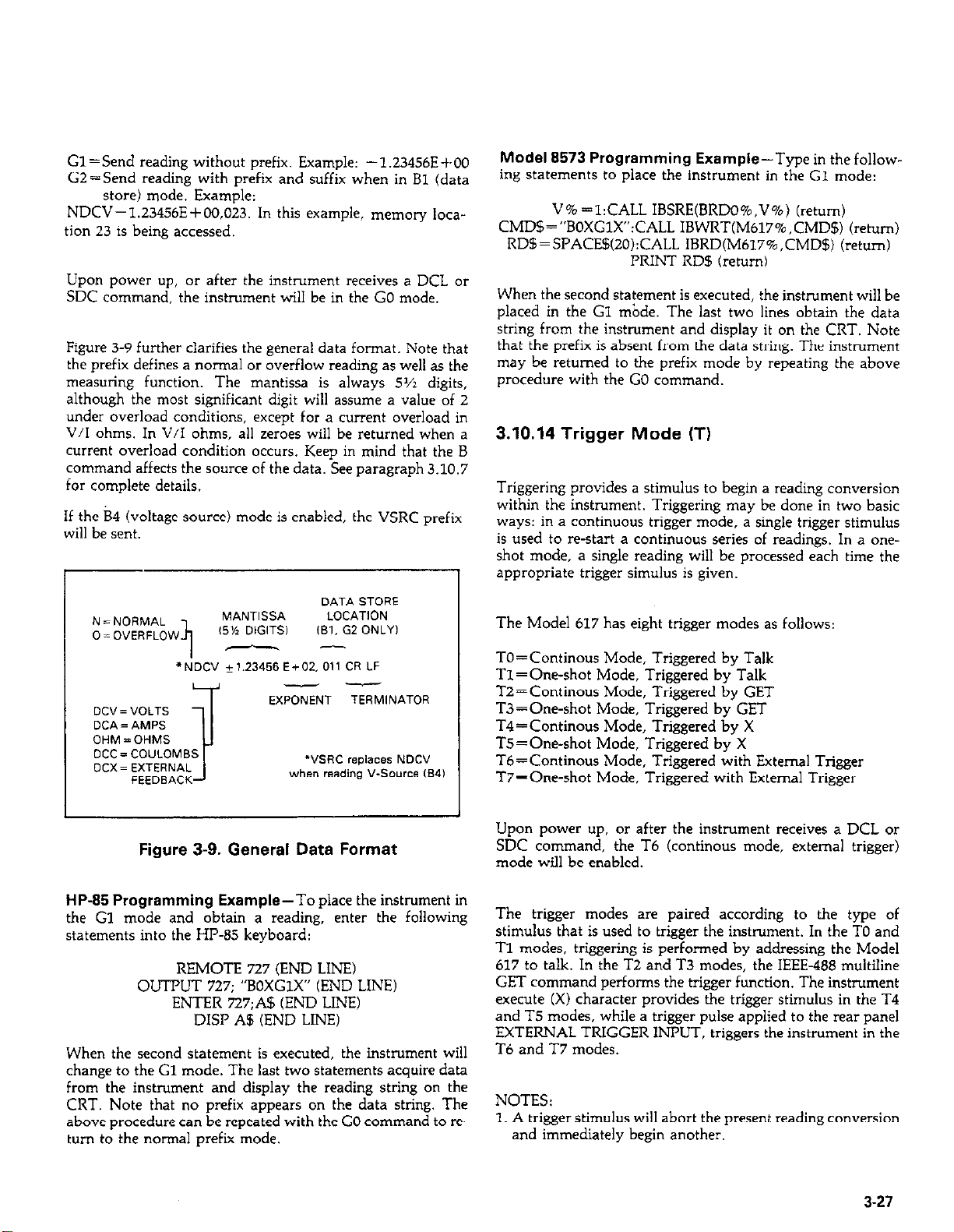
Gl =Send reading without prefix. Example: -l.Z3456E+OO
GZ=Send reading with prefix and suffix when in BI (data
store) mode. Example:
NDCV-1.23456E+OO,023. In this example, memory loca-
tion 23 is being accessed.
Upon power up, or after the instrument receives a DCL or
SDC command, the instrument will be in the GO mode.
Figure 3-9 further clarifies the general data format. Note that
the prefix defines a normal or overflow reading as well as the
measuring function. The mantissa is always 5~2 digits,
although the most significant digit will assume a value of 2
under overload conditions, except for a current overload in
V/I ohms. In V/I ohms, all zeroes will be returned when a
current overload condition occurs. Keep in mind that the B
command affects the source of the data. See paragraph 3.10.7
for complete details.
If the B4 (voltage source) mode is enabled, the VSRC prefix
will be sent.
Model 8573 Programming Example-Type in thefollow-
ing statements to place the instrument in the G1 mode:
V% =l:CALL IBSRE(BRDO%,V%) (return)
CMD$=“BOXGlX”:CALL IBWRT(M617%,CMD$) (return)
RDB=SPACE5(2O):CALL IBRD(M617%,CMD$) (return)
PRINT RD5 (return)
When the second statement is executed, the instrument will be
placed in the Gl &de. The last two lines obtain the data
string from the instrument and display it on the CRT. Note
that the prefix is absent from the data string. The instrument
may be returned to the prefix mode by repeating the above
procedure with the GO command.
3.10.14 Trigger Mode (T)
Triggering provides a stimulus to begin a reading conversion
within the instrument. Triggering may be done in two basic
ways: in a continuous trigger mode, a single trigger stimulus
is used to restart a continuous series of readings. In a oneshot mode, a single reading will be processed each time the
appropriate trigger simulus is given.
DATA STORE
N = NCIRMAL
0 = OVERFLOW
“NE” *1.23456 E+m. 011 CR LF
DC”= VOLTS
DCA = AMPS
OHM=OHMS
DCC = CO”LOMBS
DCX= EXTERNAL
Figure 3-9. General Data Format
HP-85 Programming Example-To place the instrument in
the Gl mode and obtain a reading, enter the following
statements into the HP-85 keyboard:
OUTPUT 727; “BOXGlX” (END LINE)
ENTER 727;A$ (END LINE)
When the second statement is executed, the instrument will
change to the Cl mode. The last two statements acquire data
from the instrument and display the reading string on the
CRT. Note that no prefix appears on the data string. The
above procedure can be repeated with the GO command to re-
turn to the normal prefix mode.
MANTISSA
(5% DIGITS1
II
--
I
4
REMOTE 727 (END LINE)
DISP A5 (END LINE)
EXPONENT TERMlNATOR
LOCATION
,B,. G2 ONLY,
--
““SW replaces NDC”
when reading V-Source CB4)
I
The Model 617 has eight trigger modes as follows:
I
TO=Continous Mode, Triggered by Talk
Tl =One-shot Mode, Triggered by Talk
I
T2=Continous Mode, Triggered by GET
T3 = One-shot Mode, Triggered by GET
T4=Continous Mode, Triggered by X
T5=Oreshot Mode, Triggered by X
Tb=Continous Mode, Triggered with External Trigger
Ti’=One-shot Mode, Triggered with External Trigger
Upon power up, or after the instrument receives a DCL or
SDC command, the T6 (continous mode, external trigger)
mode will be enabled.
The trigger modes are paired according to the type of
stimulus that is used to trigger the instrument. In the TO and
Tl modes, triggering is performed by addressing the Model
617 to talk. In the T2 and T3 modes, the IEEE-488 multiline
GET command performs the trigger function. The instrument
execute (X) character provides the trigger stimulus in the T4
and T5 modes, while a trigger pulse applied to the rear panel
EXTERNAL TRIGGER INPUT, triggers the instrument in the
T6 and T7 modes.
NOTES:
1. A trigger stimulus will abort the present reading conversion
and immediately begin another.
3-27
Page 82
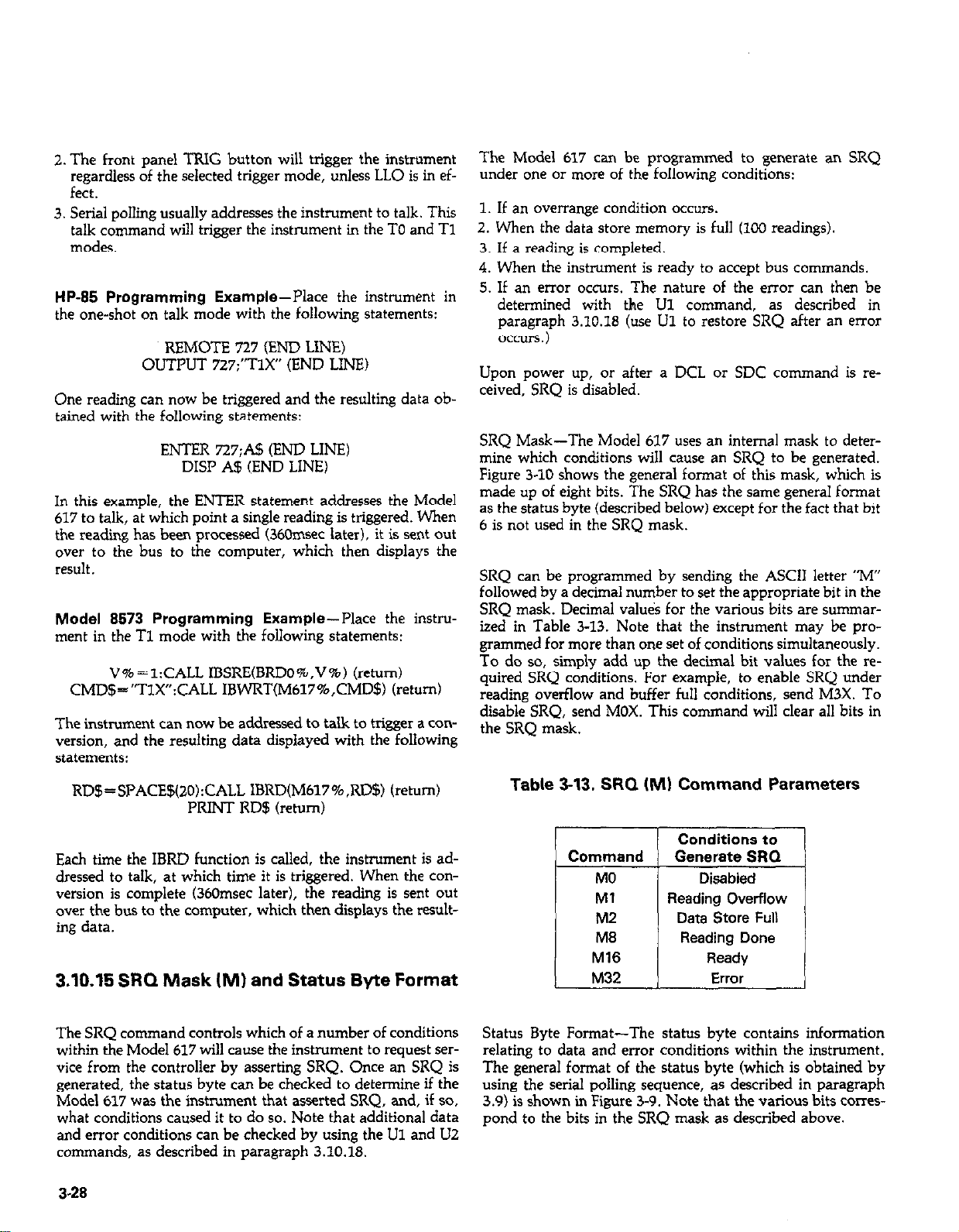
2. The front panel TRIG button will trigger the instrument
regardless of the selected trigger mode, unless LLO is in ef-
fect.
3. Serial polling usually addresses the instrument to talk. This
talk command will trigger the instrument in the TO and Tl
modes.
HP-85 Programming Example-Place the instrument in
the one-shot on talk mode with the following statements:
REMOTE 727 (END LINE)
OUTPUT 727:“TlX” (END LINE)
One reading can now be triggered and the resulting data ob-
tained with the following statements:
ENTER 727;A!$ (END LINE)
DISP A$ (END LINE)
In this example, the ENTER statement addresses the Model
617 to talk, at which point a single reading is triggered. When
the reading has been processed (360msec later), it is sent out
over to the bus to the computer, which then displays the
result.
Model 8573 Programming Example--Place the instru-
ment in the Tl mode with the following statements:
V%=l:CALL IBSRE(BRDO%,V%) (return)
CMD$=“TlX”:CALL IBWRT(M617%,CMD$) (return)
The instrument can now be addressed to talk to trigger a con-
version, and the resulting data displayed with the following
statements:
The Model 617 can be programmed to generate an SRQ
under one or more of the following conditions:
1. If an overrange condition occurs.
2. When the data store memory is full (100 readings).
3. If a reading is completed.
4. When the instrument is ready to accept bus commands.
5. If an error occurs. The nature of the error can then be
determined with the Ul command, as described in
paragraph 3.10.18 (use Ul to restore SRQ after an error
occlm )
Upon power up, or after a DCL or SDC command is received, SRQ is disabled.
SRQ Mask-The Model 617 uses an internal mask to determine which conditions will cause an SRQ to be generated.
Figure 3-10 shows the general format of this mask, which is
made up of eight bits. The SRQ has the same general format
as the status byte (described below) except for the fact that bit
6 is not used in the SRQ mask.
SRQ can be programmed by sending the ASCII letter “M”
followed by a decimal number to set the appropriate bit in the
SRQ mask. Decimal valu&s for the various bits are sununarized in Table 3-13. Note that the instrument may be programmed for more than one set of conditions simultaneously.
To do so, simply add up the decimal bit values for the required SRQ conditions. For example, to enable SRQ under
reading overflow and buffer full conditions, send M3X. To
disable SRQ, send MOX. This command will clear all bits in
the SRQ mask.
RD$=SPACE$(20):CALL IBRD(M617%,RD$) (return)
PRINT RD$ (return)
Each time the IBRD function is called, the instrument is addressed to talk, at which time it is triggered. When the conversion is complete (360msec later), the reading is sent out
over the bus to the computer, which then displays the resulting data.
3.10.15 SRQ Mask IM) and Status Byte Format
The SRQ command controls which of a number of conditions
within the Model 617 will cause the instrument to request service from the controller by asserting SRQ. Once an SRQ is
generated, the status byte can be checked to determine if the
Model 617 was the instrument that asserted SRQ, and, if so,
what conditions caused it to do so. Note that additional data
and error conditions can be checked by using the Ul and U2
commands, as described in paragraph 3.10.18.
3.28
Table 3-13. SRQ (MI Command Parameters
T
Reading Overflow
Data Store Full
Status Byte Format-The status byte contains information
relating to data and error conditions within the instrument.
The general format of the status byte (which is obtained by
using the serial polling sequence, as described in paragraph
3.9) is shown in Figure 3-9. Note that the various bits cor~es-
pond to the bits in the SRQ mask as described above.
Page 83
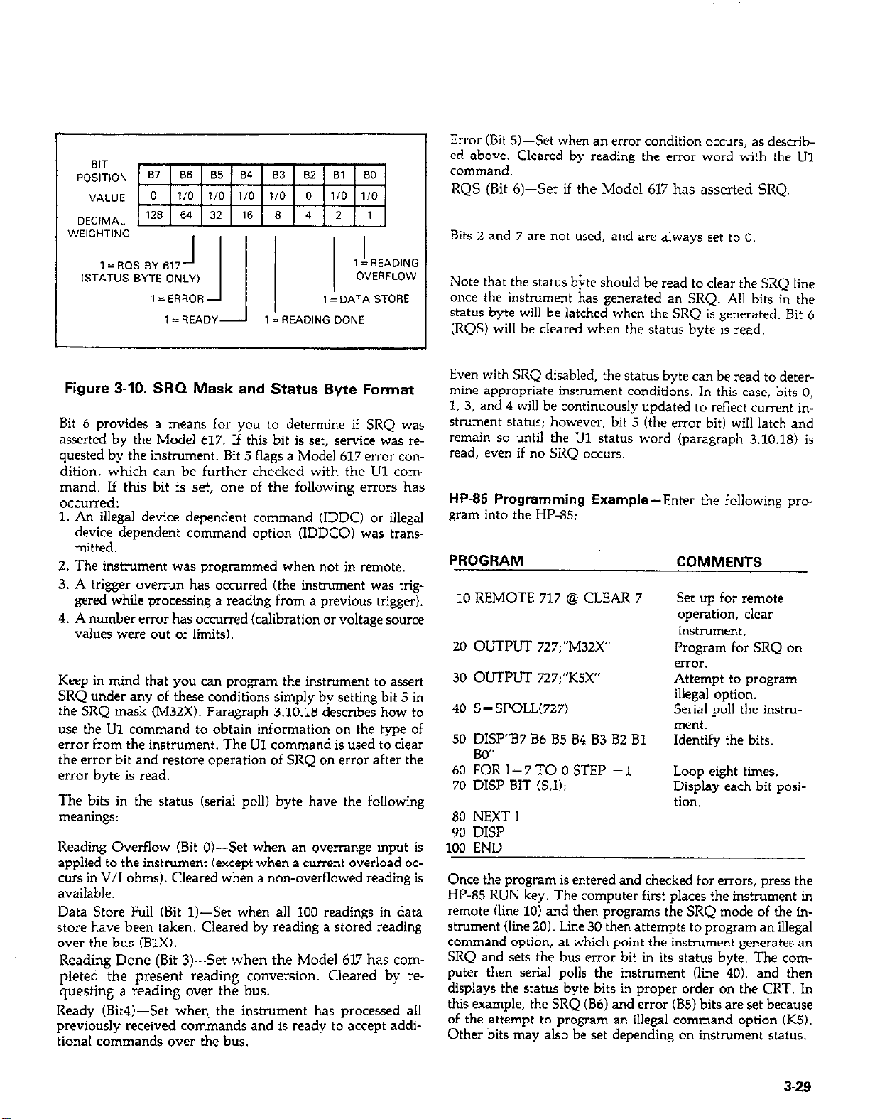
I= ROS BY 617
-I
lSTAT”S BYTE ONLY)
I= ERROR
IA
1= READY I= READING DONE
I
1 =REAOING
OVERFLOW
1 = DATA STORE
!
Figure 3-10. SRQ Mask and Status Byte Format
Bit 6 provides a means for you to determine if SRQ was
asserted by the Model 617. If this bit is set, service was requested by the instrument. Bit 5 flags a Model 617 error con-
dition, which can be further checked with the Ul cornmand. If this bit is set, one of the following errors has
occurred:
1. An illegal device dependent command (IDDC) or illegal
device dependent command option (IDDCO) was transmitted.
2. The instrument was programmed when not in remote.
3. A trigger overrun has occurred (the instrument was trig-
gered while processing a reading from a previous trigger).
4. A number error has occurred (calibration or voltage source
values were out of limits).
Keep in mind that you can program the instrument to assert
SRQ under any of these conditions simply by setting bit 5 in
the SRQ mask (M32X). Paragraph 3.10.18 describes how to
use the Ul command to obtain information on the type of
error from the instrument. The LJl command is used to clear
the error bit and restore operation of SRQ on error after the
error byte is read.
The bits in the status (serial poll) byte have the following
meanings:
Reading Overflow (Bit O&Set when an overrange input is
applied to the instrument (except when a current overload oc-
curs in V/I ohms). Cleared when a non-overflowed reading is
available.
Data Store Full (Bit 1)-&t when all 1OO readings in data
store have been taken. Cleared by reading a stored reading
over the bus (B1X).
Reading Done (Bit 3)--S& when the Model 6l7 has completed the present reading conversion. Cleared by re-
questing a reading over the bus.
Ready (Bit4)-Set when. the instrument has processed all
previously received commands and is ready to accept addi-
tional commands over the bus.
Error (Bit 5)-Set when an error condition occurs, as described above. Cleared by reading the error word with the U1
command.
RQS (Bit 6)--S& if the Model 617 has asserted SRQ.
Bits 2 and 7 are not used, and are always set to 0.
Note that the status bite should be read to clear the SRQ line
once the instrument has generated an SRQ. All bits in the
status byte will be latched when the SRQ is generated. Bit 6
(RQS) will be cleared when the status byte is read.
Even with SRQ disabled, the status byte can be read to determine appropriate instrument conditions. In this case, bits 0,
1, 3, and 4 will be continuously updated to reflect current instrument status; however, bit 5 (the error bit) will latch and
remain so until the U1 status word (paragraph 3.10.18) is
read, even if no SRQ occurs.
HP-85 Programming Example-Enter the following pro-
gram into the HP-85:
PROGRAM
10 REMOTE 717 @ CLEAR 7
20 OUTPUT 727;“M32X”
30 OUTPUT 727;“KSX”
40 S = SPOLL(727)
50 DISP”B7 B6 85 84 83 B2 Bl
RW’
60 %R 1=7TO 0 STEP -1
70 DISP BIT (S.1):
80 NEXT I
90 DISP
100 END
Once the program is entered and checked for errors, press the
HP-85 RUN key. The computer first places the instrument in
remote (line 10) and then programs the SRQ mode of the instrument (line 20). Line 30 then attempts to program an illegal
command option, at which point the instrument generates an
SRQ and sets the bus error bit in its status byte. The computer then serial polls the instrument (line 40). and then
displays the status byte bits in proper order on the CRT. In
this example, the SRQ (B6) and error (B5) bits are set because
of the attempt to program an illegal command option (KS).
Other bits may also be set depending on instrument status.
COMMENTS
set up for remote
operation, clear
instrument.
Program for SRQ on
error.
Attempt to program
illegal option.
Serial poll the instrument.
Identify the bits.
Loop eight times.
Display each bit posi-
tion.
3-29
Page 84
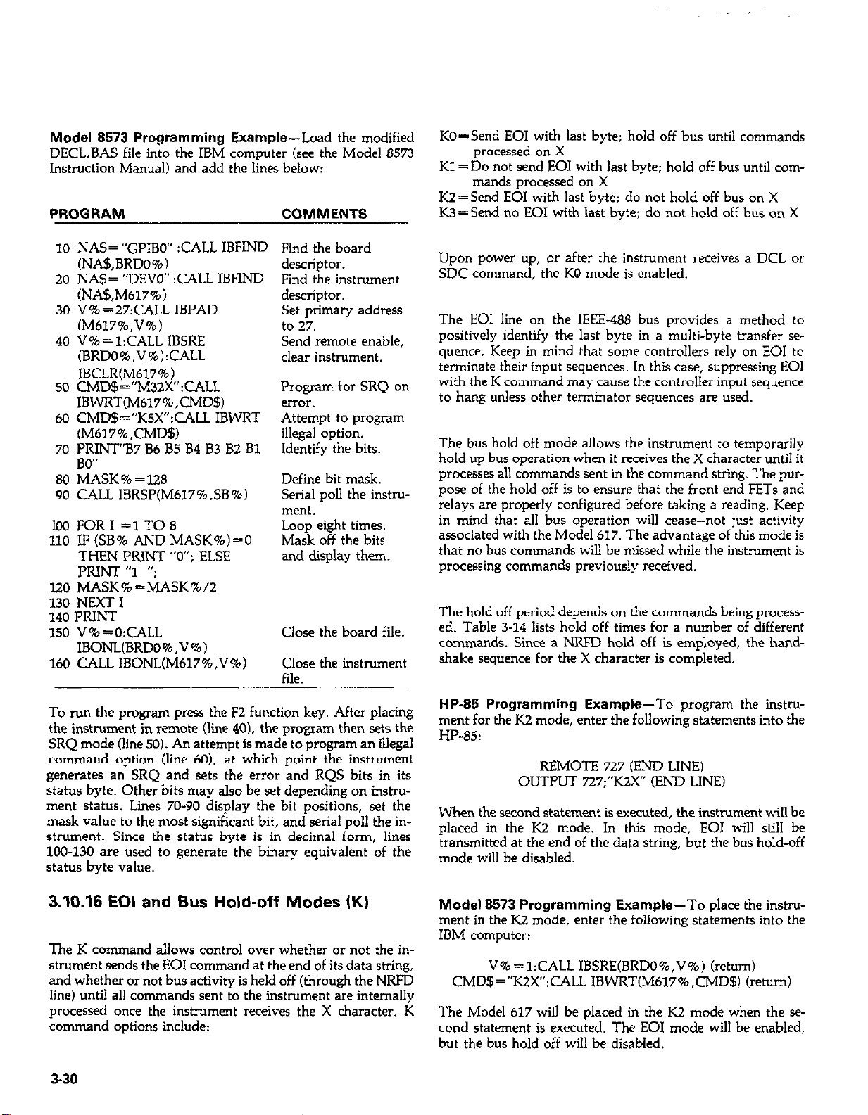
Model 8573 Programming Example-Load the modified
DECL.BAS file into the IBM computer (see the Model 8573
Instruction Manual) and add the lines below:
PROGRAM COMMENTS
KO=Send EOI with last byte; hold off bus until commands
processed on X
Kl=Do not send EOI with last byte; hold off bus until com-
mands processed on X
K2=Send EOI with last byte; do not hold off bus on X
IW=Send no EOI with last byte; do not hold off bus on X
10 NA$=“GPIBO” :CALL IBFIND Find the board
(NA$,BRDO%) descriptor.
20 NA$= “DEVO” :CALL IBFIND Find the instrument
(NAS,M617% ) descriutor.
30 V% =27:CALi IBPAD
(M617%,V%)
40 V% = l:CALL IBSRE
(BRDO%,V%):CALL
Set phmary address
to 27.
Send remote enable,
clear instrument.
IBCLR(M617%)
50 CMDS = “M32X” :CALL
IBWRT(M617%,CMD$l
60 CMD$=“KSX”:CALL IBWRT
(M617%,CMD$l
70 PRINT”B7 B6 B5 B4 83 B2 Bl
Program for SRQ on
aTor.
Attempt to program
illegal option.
Identify the bits.
80”
80 MASK % = 128
90 CALL IBRSP(M617%,SB%)
Define bit mask.
Serial poll the instmmerit.
100 FORI =1TO8
110 IF (SB% AND MASK%)=0
THEN PRINT “0”; ELSE
Loop eight times.
Mask off the bits
and display them.
PRINT “1 “;
120 MASK%=MASK%/2
130 NEXT I
140 PRINT
150 V% =O:CALL
Close the board file.
IBONL(BRDO%,V%)
160 CALL IBONL(M617%,V%) Close the instrument
file.
Upon power up, or after the instrument receives a DCL or
SDC command, the KQ mode is enabled.
The EOI line on the IEEE-486 bus provides a method to
positively identify the last byte in a multi-byte transfer sequence. Keep in mind that some controllers rely on EOI to
terminate their input sequences. In this case, suppressing EOI
with the K command may cause the controller input sequence
to hang unless other terminator sequences are used.
The bus hold off mode allows the instrument to temporarily
hold up bus operation when it receives the X character until it
processes all commands sent in the command string. The purpose of the hold off is to ensure that the front end FETs and
relays are properly configured before taking a reading. Keep
in mind that all bus operation will cease-not just activity
associated with the Model 617. The advantage of this mode is
that no bus commands will be missed while the instrument is
processing commands previously received.
The hold off period depends on the commands being processed. Table 3-14 lists hold off times for a number of different
commands. Since a NRFD hold off is employed, the handshake sequence for the X character is completed.
To run the program press the F2 function key. After placing
the instrument in remote (line 40). the program then sets the
SRQ mode (line 50). An attempt is made to program an illegal
command option (line 60). at which point the instrument
generates an SRQ and sets the error and RQS bits in its
status byte. Other bits may also be set depending on instrument status. Lines 70-90 display the bit positions, set the
mask value to the most significant bit, and serial poll the instrument. Since the status byte is in decimal form, lines
100-130 are used to generate the binary equivalent of the
status byte value.
3.10.16 EOI and Bus Hold-off Modes (K)
The K command allows control over whether or not the instrument sends the EOI command at the end of its data string,
and whether or not bus activity is held off (through the NRFD
line) until all commands sent to the instrument are internally
processed once the instrument receives the X character. K
command options include:
3-30
HP-85 Programming Example-To program the instm-
ment for the K2 mode, enter the following statements into the
HP-85:
REMOTE 727 (END LINE)
OUTPUT 727;“K2x” (END LINE)
When the second statement is executed, the instrument will be
placed in the K2 mode. In this mode, EOI will still be
transmitted at the end of the data string, but the bus hold-off
mode will be disabled.
Model 8573 Programming Example-To place the instm-
ment in the K2 mode, enter the following statements into the
IBM computer:
V%=l:CALL IBSRE(BRDO%,V%) (return)
CMD$=“KZX”:CALL IBWRT(M617%,CMD$) (retom)
The Model 617 will be placed in the K2 mode when the second statement is executed. The EOI mode will be enabled,
but the bus hold off will be disabled.
Page 85
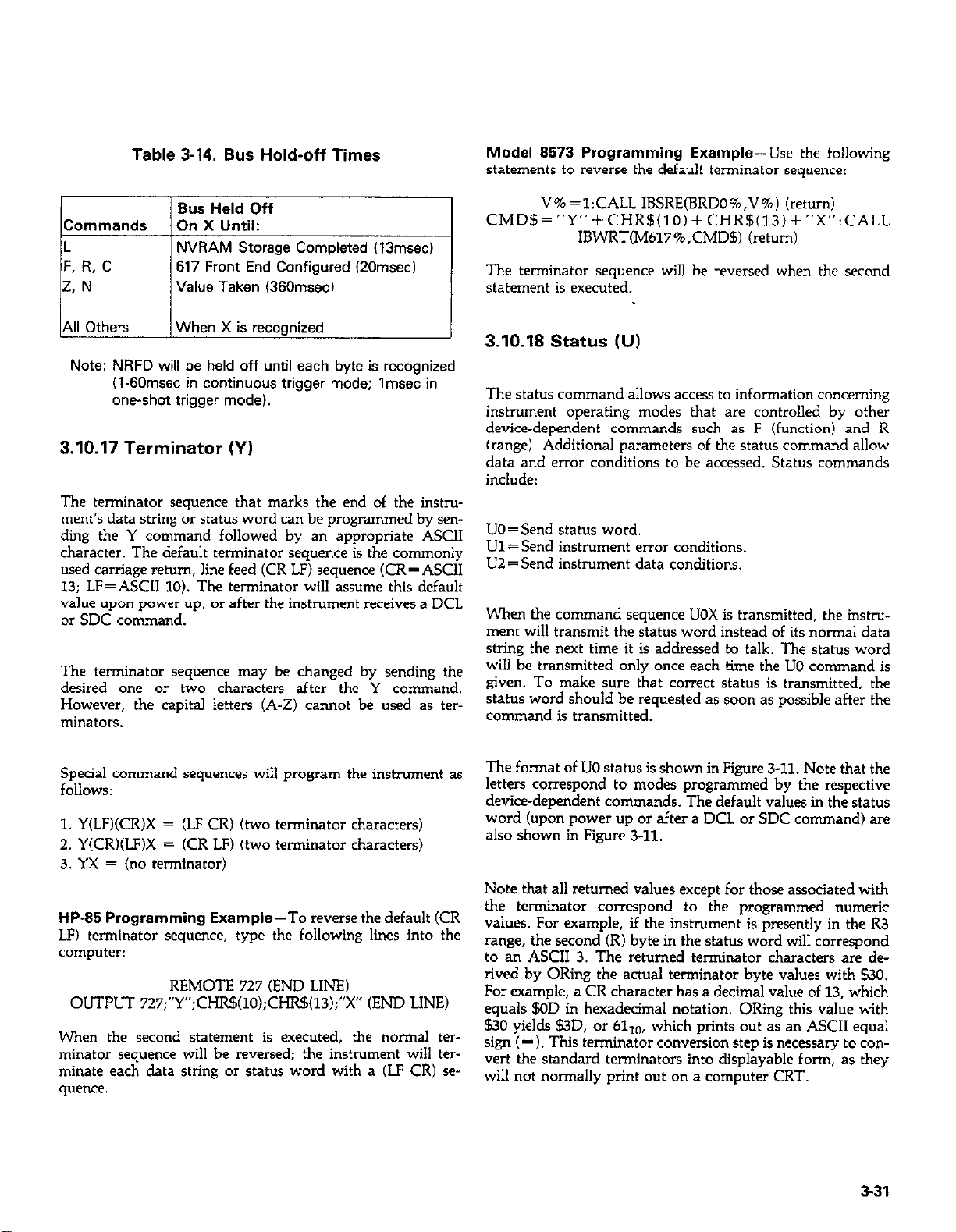
Table 3-14. Bus Hold-off Times
Model 8573 Programming Example-Use the following
statements to reverse the default terminator sequence:
Bus Held Off
Commands On X Until:
L
F. R, C
2. N
All Others
Note: NRFD will be held off until each byte is recognized
NVRAM Storage Completed (13msec)
617 Front End Configured (20msecl
Value Taken (36Omsec)
When X is recognized
(1.60msec in continuous trigger mode; Imsec in
one-shot trigger model.
3.10.17 Terminator (Y)
The terminator sequence that marks the end of the instrument’s data string or status word can be programmed by sending the Y command followed by an appropriate ASCII
character. The default terminator sequence is the commonly
used carriage return, line feed (CR LF) sequence (CR=ASCII
13: LF=ASCII 10). The terminator will assume this default
value upon power’up, or after the instrument receives a DCL
or SDC command.
The terminator sequence may be changed by sending the
desired one or two characters after the Y command.
However, the capital letters (A-Z) cannot be used as terminators.
V%=l:CALL IBSRE(BRDO%,V%) (return)
CMD!§=“Y”+CHR$(lO)+CHR$(13)+“X”:CALL
IBWRT(M617%,CMD$) (return)
The terminator sequence will be reversed when the second
statement is executed.
3.10.18 Status NJ)
The status command allows access to information concerning
instrument ooeratinz modes that are controlled bv other
device-dependent c&mands such as F (functionj’and R
(range). Additional parameters of the status command allow
data and error conditions to be accessed. Status commands
include:
UO=Send status word.
Ul=Send instrument error conditions.
UZ=Send instrument data conditions.
When the command sequence UOX is transmitted. the instrument will transmit the status word instead of its normal data
string the next time it is addressed to talk. The status word
will be transmitted only once each time the UO command is
given. To make sure that correct status is transmitted, the
status word should be requested as soon as possible after the
command is transmitted.
Special command sequences will program the instrument as
follows:
1. Y(LF)(CR)X = (LF CR) (two terminator characters)
2. Y(CR)(LF)X = (CR LF) (two terminator characters)
3. YX = (no terminator)
HP-85 Programming Example-To reverse the default (CR
LF) terminator sequence, type the following lines into the
computer:
REMOTE 727 (END LINE)
OUTPUT 727;“Y”;CHR$(lO);CHR!§(l3);“X” (END LINE)
When the second statement is executed, the normal terminator sequence will be reversed; the instrument will terminate each data string or status word with a (LF CR) sequence.
The format of UO status is shown in Figure 3-11. Note that the
letters correspond to modes programmed by the respective
device-dependent commands. The default values in the status
word (upon power up or after a DCL or SDC command) are
also shown in Figure 3-11.
Note that al1 returned values except for those associated with
the terminator correspond to ihe programmed numeric
values. For example, if the instrument is presently in the R3
range, the second (R) byte in the statLls word will correspond
to an ASCII 3. The returned terminator characters are derived by ORing the actual terminator byte values with $30.
For example, a CR character has a decimal value of 13, which
equals $OD in hexadecimal notation. ORing this value with
$30 yields $3D, or 6110, which prints out as an ASCII equal
sign (= ). This terminator conversion step is necessary to convert the standard terminators into displayable form, as they
will not normally print out on a computer CRT.
3-31
Page 86
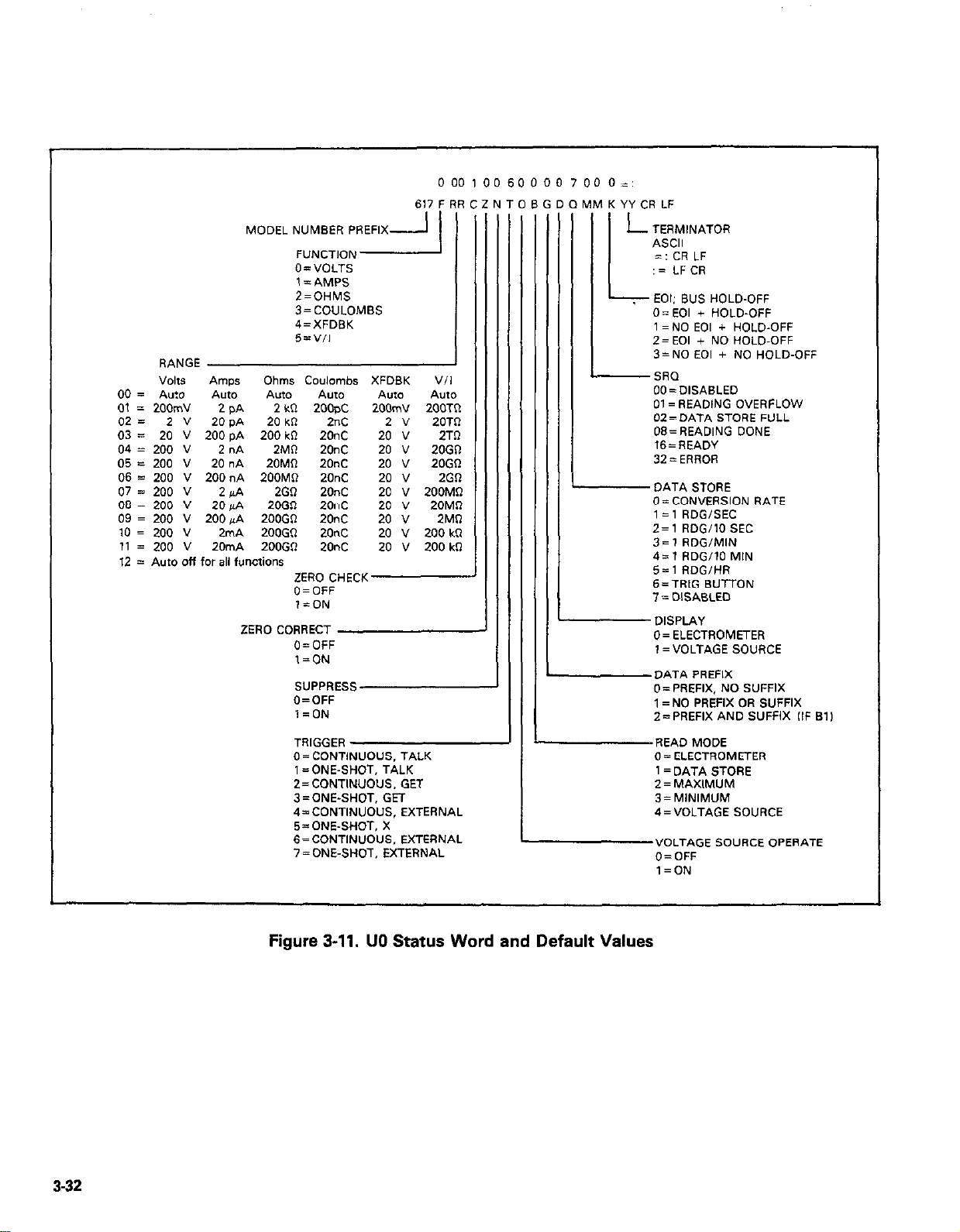
617 F RR
O=VOLTS
1= AMPS
2=OHMS
3=COULOMBS
4=XFDElK
5=“,I
RANGE
“Ok* AnyIS Ohms Coulombs XFDSK
00 = A”:0 A”fO ANO AU10 A”W AU10
01 = 200mV
02= 2” 20 pA 20 k* 2nC 2 v 20TR
03 = 20 V 200 pA 200 kR 20°C 20 ” 2Tfl
04 = 200 v 2 “A 2MO 20nC 20 ” 20Gll
05 = 200 v 20 nA 20MR 20°C 20 ” 20GQ
06 = 200 V 200nA 200MR 20nC 20 ” 2GR
07 = 200 V 2 PA 2GR 20nC 20 v 200MR
08 = 200 v 20&A 20GR 20°C 20 ” 20MR
09 = 200 V 200gA ZOOGO 20nc 20 v 2MQ
10 = 200 v 2mA ZOOGR 20nc 20 v 200 k0
11 = 200 v 20mA 200GfI 20nc 20 ” 200 id2
12 = Auto off for all functions
2 PA
2kcl zoo$c
ZERO CHECK
O=OFF
,=ON
ZERO CORRECT
O=OFF
l=ON
SUPPRESS
O=OFF
l=ON
TRIGGER A
0 = CONTINUOUS. TALK
1= ONE-SHOT, TALK
2= CONTINUOUS, GET
3=ONE-SHOT. GET
4=CONTINUOUS. EXTERNAL
5=ONE-SHOT. X
6=CONTINUOUS. EXTERNAL
7=ONE-SHOT, EXTERNAL
2OOmV 2OOTtl
“/I
ulM K YY CR LF )BGDOI
L
TERMINATOR
ASCII
=:CRLF
:= LFCR
k EOI: BUS HOLD-OFF
O=EOI + HOLD-OFF
1 =NO EOI + HOLD-OFF
2=EOI + NO HOLD-OFF
3=NO EOI + NO HOLD-OFF
-sm
OO=DISASLEO
01= READING OVERFLOW
OZ=DATA STORE i=“LL
08=READING DONE
16=READY
32 = ERROR
DATA STORE
O=CONVERSION RATE
1= 1 RDGISEC
2=1 RDGilO SEC
3= 1 RDGIMIN
4=1 RDG/lO MIN
5=1 RDG,HR
B=TRIG SUTTON
7 = DISABLED
DISPLAY
0= ELECTROMETER
1 =VOLTAGE SOURCE
DATA PREFIX
O=PREFIX. NO SUFFIX
1 = NO PREFIX OR SUFFIX
Z=PREFIX AND SUFFIX ,IF Bl,
-
I
READ MODE
0= ELECTROMETER
I= DATA STORE
2=MAXIMUM
3= MINIMUM
4=VOLTAGE SOURCE
VOLTAGE SOURCE OPERATE
O=OFF
l=ON
332
Figure 3-11. UO Status Word and Default Values
Page 87
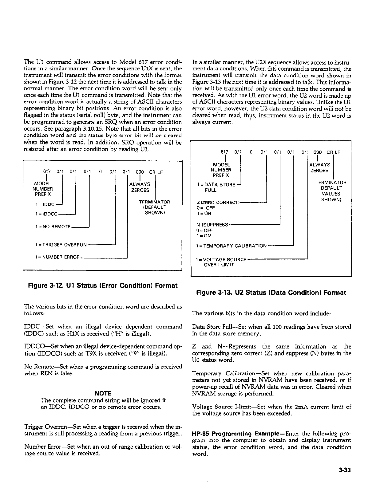
The Ul command allows access to Model 617 error conditions in a similar manner. Once the sequence UlX is sent, the
instrument will transmit the error conditions with the format
shown in Figure 3-12 the next time it is addressed to talk in the
normal manner. The error condition word will be sent only
once each time the Ul command is transmitted. Note that the
error condition word is actually a string of ASCII characters
representing binary bit positions. An error condition is also
flagged in the status (serial poll) byte, and the instrument can
be programmed to generate an SRQ when a” error condition
OCCWS. See paragraph 3.10.15. Note that all bits in the error
condition word and the status byte error bit will be cleared
when the word is read. In addition, SRQ operation will be
restored after an error condition by reading Ul.
r
617 Oil O/l 0,
I= IDDCO-
0 0
000 CR LF
,LWAYS
ZEROES
TERMINATOR
(DEFAULT
SHOWN1
In a similar manner, the U2X sequence allows access to instrument data conditions. When this command is transmitted, the
instrument will transmit the data condition word shown in
Figure 3-13 the next time it is addressed to talk. This information will be transmitted only once each time the command is
received. As with the Ul error word, the U2 word is made up
of ASCII characters representing binary values. Unlike the Ul
error word, however, the LIZ data condition word will not be
cleared when read; thps, instrument status in the U2 word is
always current.
0,
iI
A
000 CR LF
I
.LWAYS
!EROES
TERMINATOR
,DEFAULT
1
1 = DATA STORE J
2 (ZERO CORRECT)
0= OFF
l=ON
617 Oil 0 Oil o/1 0.
MODEL
NUMBER
PREFIX
FULL
1
VALUES
1= NO REMOTE -
1 1 = NUMBER ERROR
Figure 3-12. Ul Status (Error Condition) Format
The various bits in the error condition word are described as
follows:
IDDC-Set when a” illegal device dependent command
(IDDC) such as HlX is received (“H” is illegal).
IDDCO-Set when a” illegal device-dependent command op-
tion (IDDCO) such as T9X is received (“9” is illegal).
No Remote-Set when a programming command is received
when REN is false.
NOTE
The complete command string will be ignored if
an IDDC. IDDCO or no remote error occurs.
N (SUPPRESS1
O=OFF
l=ON
1 =TEMPORARY CALlSRATlON-
1 =“OLTAGE SOURCE
OVER I-LIMIT
Figure 3-13. U2 Status (Data Condition) Format
The various bits in the data condition word include:
Data Store Full-Set when all 100 readings have been stored
in the data store memory.
Z and N-Represents the same information as the
corresponding zero correct (Z) and suppress (N) bytes in the
UO status word.
Temporary Calibration-Set when new calibration parameters not yet stored in NVRAM have been received, or if
power-up recall of NVRAM data was in error. Cleared when
NVRAM storage is performed.
Voltage Source I-limit-Set when the 2mA current limit of
the voltage source has been exceeded.
Trigger Overrun-Set when a trigger is received when the instrument is still processing a reading from a previous trigger.
Number Error-Set when a” Out of range calibration or voltage source value is received.
HP-85 Programming Example-Enter the following pro-
gram into the computer to obtain and display instrument
status, the error condition word, and the data condition
word.
3-33
Page 88
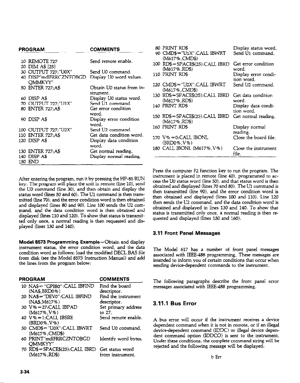
PROGRAM COMMENTS
10 REMOTE 727
Send remote enable.
20 DIM AS 1251
30 OuTPIJT 727:“UOX” Send UO command.
40 DW”mdlFRRCZNTOBGD Display UO word values
QMMKYY”
50 ENTER 727;A$
Obtain UO status from in-
strument.
60 DISP A$
70 OUTPUT 727;“Ulx”
80 ENTER 727;A$
Display UO status word
Send U1 command.
Get error condition
word.
90 DISP A$
Display error condition
word.
100 OUTPUT 727:“U2X”
110 ENTER 727;A!J
120 DISP A$
Send U2 command.
Get data condition word.
Display data condition
word.
130 EmR 727:A$
140 DISP A$
Get normal reading.
Display normal reading.
150 END
80 PRINT RD$
90 CMD$=“UlX”:CALL IBWRT
(M617%,CMD5)
100 RD$=SPACE$(ZS):CALL IBRD
(M617%,RD$)
1.10 PRINT RD$
120 CMD$=“UZX”:CALL IBWRT
(M617%,CMD$)
130 RD$=SPACE$(2S):CALL IBRD
(M617%,RD$)
140 PRIh’T RD$
150 RD$= SPACE$(25):CALL IBRD
(M617%,RD$)
160 PRINT RD$
170 V% =O:CALL IBONL
(BRDO%,V%)
180 CALL IBONL (M617%,V%)
Display status word.
Send Ul command.
Get error condition
word.
Display error condition word.
Send IJ2 command.
Get data condition
word.
Display data condition word.
Get normal reading.
Display normal
reading.
Close the board file.
Close the instrument
file.
After entering the program, run it by pressing the HP-85 RUN
key. The program will place the unit in remote (line 10). send
the UO command (line 30). and then obtain and display the
status word (lines 50 and 60). Th e Ul command is
mitted (line 70). z
md the error condition word is thj en obtained
then trans-
and displayed (lines 80 and 90). Line 100 sends the U2 command, and the data condition word is then obtained and
displayed (lines 110 and 120). To show that status is transmitted only once, a normal reading is then requested and displayed (lines 130 and 140).
Model 8573 Programming Example-Obtain and display
instrument status, the error condition word, and the data
condition word as follows: load the modified D--’ - IS file ‘tCL.LI~
from disk (see the Model 8573 Instruction Manual) and add
the lines from the program below:
PROGRAM
COMMENTS
10 NA!J= “GPIBO” :CALL IBFIND Find the board
(NA$,BRDO%) descriptor.
20 NA$=“DEVO”:CALL IBFIND Find the instrument
(NA!f+M617%)
30 V% =27:CALL IBI’AD
(M617%,V%)
40 V%=l:CALL IBSRE
descriptor.
Set primary address
to 27.
Send remote enable.
(BRDO%,V%)
50 CMD$=“LIOX”:CALL IBWRT Send UO command.
(M617%,CMD$)
60 PRINT”mdlFRRCZNTOBGD Identifv word bvtes.
QMMKYY”
70 RD$=SPACE$QS):CALL IBRD Get status word
(M617%,RD$) from instrument.
Press the conmuter F2 function kev to run the moeram. The
. ”
instrument is placed in remote (line 40). programmed to access the UO status word (line 50). and that status word is then
obtained and displayed (lines 70 and 80). The Ul command is
then transmitted (line 90). and the error condition word is
then obtained and displayed (lines 100 and 110). Line 120
then sends the U2 command, and the data condition word is
obtained and displayed in lines 130 and 140. To show that
status is transmitted only once, a normal reading is then requested and displayed (lines 150 and 160).
3.11 Front Panel Messages
The Model 617 has a number of front panel messages
associated with IEEE-488 programming. These messages are
intended to inform you of certain conditions that occur when
sending device-dependent commands to the instrument.
The following paragraphs describe the front panel error
messages associated with IEEE-488 programming.
3.11.1 Bus Error
A bus error will occur if the instrument receives a device
dependent command when it is not in remote, or if an illegal
device-dependent command (IDDC) or illegal device dependent command option (IDDCO) is sent to the instrument.
Under these conditions, the complete command string will be
rejected and the following message will be displayed:
b Err
3-34
Page 89
In addition, the error bit and pertinent bits in the Ul word
will be set (paragraph 3.10.15 and 3.10.18) and the instmment can be programmed to generate an SRQ under these
conditions (paragraph 3.10.15).
A no remote error can occur when a command is sent to the
instrument when the REN line is false. Note that the state of
REN is only tested when the X character is received. An
IDDC error can occur when an invalid command such as
HlX is transmitted (this command is invalid because the instrument has no command associated with that letter).
Similarly, an IDDCO error occurs when an invalid option is
sent with a valid command. For example, the command T9X
has an invalid option because instrument has no such trigger
mode.
HP-85 Programming Example-To demonstrate a bus er-
ror, send an IDDC with the following statements:
REMOTE 727 (END LINE)
OUTPUT 717:“HlX” (END LINE)
When the second statement is executed, the bus error message
appears on the display for about one second.
Model 8573 Programming Example-Type in the follow-
ing statements to demonstrate a bus error by sending an IDDCO:
V% =l:CALL IBSRE(BRDO%,V%) (rehxn)
CMD$=“HlX”:CALL IBWRT(M617%,CMD$) (return)
When the second statement is executed, the instrument will
display the number error message for about one second. This
error occurs with this example because an attempt is made to
program a voltage value of 125V, which is outside the range
of the voltage source (-102.35V 5 V 5 +102.4V).
Model 8573 Programming Example-To display the
number error, enter the following lines into the IBM computer:
V%=l:CALL IBSRE(BRDO%,V%) (return)
CMDB=“DlVl25X”:CALL IBWRT(M617%,CMD$)
(return)
The number error message will be displayed for about one se-
cond when the second statement is executed. The number er-
ror occurs with this example because of the attempt to program a voltage of 125V, which is above the range of the
voltage source (-102.35V 5 VI +102.4V).
3.11.3 Trigger Overrun Error
A trigger overrun error occurs when the instrument receives a
trigger while it is still processing a reading from a previous
trigger. Note that only the overrun triggers are ignored and
will have no effect on the instrument except to generate the
message below. When a trigger overrun occurs, the following
front panel message will be displayed for approximately one
second:
t Err
The bus error message will be displayed for about one second
when the second statement is executed.
3.11.2 Number Error
A number error occurs when an out of range value is sent to
the instrument when programming the voltage source, or
when sending calibration values over the bus. Under these
conditions, the instrument will display the following error
message:
“Err
The command string will be accepted, but calibration or
voltage values will remain unchanged.
HP-85 Programming Example-Enter the following lines
to display a number error:
REMOTE 727 (END LINE)
OUTPUT 727;“DlV125X” (END LINE)
HP-85 Programming Example-To demonstrate a trigger
overrun error, enter the following statements into the HP-85
keyboard:
REMOTE 727 (END LINE)
OUTPUT 727;‘T3x” (END LINE)
TRIGGER 727@TRIGGER 727 (END LINE)
Note that the trigger overrun message is displayed with the
third line above is executed.
Model 8573 Programing Example-Enter the following
statements into the computer to demonstrate the trigger over-
run message:
V%=l:CALL IBSRE(BRDO%,V%) (return)
CMD$=“T3X”:CALL IBWRT(M617%,CMD$) (return)
CALL IBTRG(M617%):CALL IBTRG(M617%) (return)
The trigger overrun error message will be displayed when the
third line above is executed.
3-35
Page 90

Table 3-15. Trigger to Reading-Ready Times
3.12 Bus Data Transmission Times
T
ErrIN
Time (msec
365
780
204, 200nA. 20nA
1;;; &A 2~
l20nC. 2nC
l2oopc
20kS200GQ
2kL-I
Notes:
1. Conditions: Input is on range, HP-85 controller.
2. Preamp settling time (to 12%) is 2 seconds on preamp
ranges (2,20,20OpA), and must be taken into account by
the user.
3. Volt time/error also apply to external feedback.
4. V/I time/error is the same es the applicable current range.
365
365
780
780
365
780
365
780
% of step Input
1 f
t
I
.Ol
.lO
.Ol
55 (2)
.lO
25 (2)
.Ol
.lO
.Ol
.lO
A primary consideration is the length of time it takes to ob-
tain a reading once the instrument is triggered to make a conversion. The length of time will vary somewhat depending on
the selected function and trigger mode. Table 3-15 gives
typical times
3-36
Page 91
SECTION 4
APPLICATIONS
4.1 INTRODUCTION
Applications for the Model 617 are many and varied and will
depend on the user’s needs. Basically, the Model 617 can be
used to make many of the same measurements in the range of
ordinary DMMs; however, special characteristics such as
high input resistance and high sensitivity give the instrument
much better capabilities than those of the ordinary DMM.
For example, the typical input resistance for an ordinary
DMM is on the order of lOM0. In contrast, the Model 617
has an input resistance of greater than ZOOTQ (2 x 10143).
The Model 617 can detect currents as low as O.lfA (lo-16A),
while a typical DMM might be limited to current measurements in the pA range.
In this section, then, we will discuss some possible applications for the Model 617 Electrometer. Keep in mind that these
examples are only representative of what is possible with this
highly sophisticated instrument, and by no means exhaust the
possible uses for the unit.
4.2 INSULATION RESISTANCE
MEASUREMENTS
constant. The voltage developed across the test resistance
will, of course, depend on the value of the insulation resis-
tance. The Model 617 measures the generated voltage and
calculates the resistance value accordingly. The low compliance voltage of the Model 617 ( < 2V on 2G0 range and
lower, except <3OOV during overload) keeps error due to
voltage coefficient small.
For resistance measurements above 1080, or for cables longer
than three feet, guarded measurements are recommended, as
shown in Figure 4-2. In this case, the rear panel V, R GUARD
switch is used to internally apply a guard signal to the inner
shield on the connecting cable. The guard is carried through
to the inner shield of the test fixture. The inner shield must be
insulated from the outer shield, which is a safety shield. Incidentally, a shielded fixture is recommended for both
unguarded and guarded configurations for measurements
above 107n if stable readings are to be expected (in the
unguarded mode, the shield should be connected to input
IOW).
With the constant current method just discussed, the Model
617 can make rneasurenients as high as 200GR. However, the
insulation resistance of such materials as polyethylene may lie
above this range. By using the Model 617 to make resistance
measurements in the constant-voltage mode, measurement
range can be extended up to 10160. Also, for a given
resistance range, the V/I mode will be faster.
At the moderate impedance levels of many circuits, insulation
resistance is seldom a consideration, as it is generally many
orders of magnitude above the highest impedance encountered in the remainder of the circuit. At very high impedance levels, however, insulation resistance can be a consideration, since it can lower effective circuit impedance considerably. Since typical insulation resistances run in the range
of lOlo-lOM2, their values lie above the measurement range
of ordinary instruments. The high resistance measurement
range of the Model 617, however, gives it capabilities to
measure such high resistances.
A typical test configuration for making insulation resistance
measurements is shown in Figure 4-l. In this case, the constant current method is used. Using this method, insulation
resistances up to 2WGfI can be measured. As the term irn-
plies, the tet current through the unknown resistance is kept
A typical configuration for using the Model 617 in this manner is shown in Figure 4-3. Here, the built in voltage source of
the instrument is used to force a current, I, through the
unknown resistance, R. The insulation resistance is then
automatically calculated by the Model 617 as follows:
V
R=-
I
where I is the current through the resistance as measured by
the instrument, and V is the programmed voltage.
Note that COM is connected to input LO thru 1OGQ and appears in series with the resistor under test. This resistance is
below the resolution of the instrument on ranges above
2MSl.
4-l
Page 92

MODEL 6147
,&R:;;,, ,A
II
\
INPUT
00
MODEL 4801
I
0
00 00
0
-0 cl
617 SET TO OHMS
il
\
r-----l
4-2
EQUIVALENT CIRCUIT
Figure 4-l. Insulation Resistance Measurement (Unguarded)
Page 93

00
INPUT
6011 CABLE
I1
--
r---
OFF m ON
VR GUARD - ’ u
-----_
r
617 SET TO OHMS, “. ff GUARD ON
1
I-----
WARNING: SAFETY SWELO RECOMMENDED FOR GUARDED
I
COM 617 PREAMP
)I’
If---l
RESISTANCE MEASUREMENTS ABOVE 30GR. UP
TO 300” MA,’ SE PRESENT ON GUARD
L--J--
SAFETY
SHIELD
A/D CONVERTER
>
SIGNAL
GUARD
EQUIVALENT CIRCUIT
Figure 4-2. Insulation Resistance Measurement (Guarded1
4-3
Page 94

MODEL 6147 TRIAX
TO BNC ADAPTER
\
/
r
MODEL 4601 CABLE
---_
r----
\
0
00 00
V-SOURCE OUTPUT
\Lo\J ,o, F
\ ’
6104 TEST FIXTURE
----__
617 SET TO “II OHMS
POMONA MODEL 4666 PATCH CORDS
617 PREAMP
Ryj+” &&&y&&
Y
MODEL 6104
TEST FIXTURE
I
A/D CONVERTER
BLACK
SHIELDED
4.4
z V-SOURCE
T
EQUIVALENT CIRCU,T
Figure 4-3. Insulation Resistance Measurement Using V/I Ohms Mode
Page 95

For example, assume that the applied voltage is 1OOV. and the
measured current is 1pA. The resistance is calculated as
follows:
The percent error due to voltmeter loading in this circuit can
be given as:
V
100
R =-=_=
I
IPA
Since the user has fine control over the internal voltage source
(-102.35V to +102.4V in 5OmV steps), the resistance at a
given applied voltage can be easily determined. Such control
can give rise to voltage coefficient studies, as described later
in this section.
In addition to the measurement of insulation resistances, this
basic method can be used to measure unwanted leakage resis-
tances. For example, leakage resistance between PC board
traces and connectors can be made with either of the two
methods above, depending on the resistance values involved.
10140
4.3 HIGH IMPEDANCE VOLTMETER
The input resistance of the Model 617 in the volts mode is
greater than ZOOTQ. Because of this high value, the Model 617
can be used to make voltage measurements in high impedance
circuits with a minimum of loading effects on the circuit.
Consider the situation where a circuit designer must measure
the gate-to-source voltage of a precision JFET amplifier that
has a gate impedance of 1COMQ. Further assume that the re-
quired accuracy of this measurement is 1%
% ERROR =
Suppose, for example, a typical DMM with a 1OMR input
resistance were used to make this measurement. The error
because of meter loading would be:
% ERROR =
Even if a DMM with an input resistance of 1OW were used,
the error would still be:
% ERROR = x 100% = 9.1% error
Such a large error would not be tolerable in this case because
of the 1% accuracy requirement. However, since the Model
617 has an input resistance of 200TR. its error in this example
would be:
%ERROR = x 100% = O.oooo5% error
which would be dominated by the instrument’s specified accuracy.
RS
Rs + RIN
1OOMQ
1OOMR + lOMQ
1OOMQ
lC0MQ + 1GO
lWM0
1OOMQ + 2OOTQ
x 100%.
x 100% = 91% elm2
The set-up for this measurement is shown in Figure 4-4. The
gate-source voltage is represented by VGS, while the effective
gate impedance is represented as Rs. The input resistance of
the voltmeter is given as RN.
A. MEASUREMENT
CONFIGURATION
v
B. EWIVALENT CIRCUIT
Figure 4-4. Measuring High Impedance Gate-
Source Voltage
Thus, the input impedance of the Model 617 would be more
than adequate for this situation, because the error due to
meter loading is substantially better than the required 1%
value stated earlier. In addition, the 4~ digit resolution of the
instrument allows the designer sufficient precision to make
use of the high input impedance.
4.4 LOW-LEVEL LEAKAGE CURRENT
MEASUREMENTS
Many devices exhibit low-level leakage currents that may require measurement. Typically, such leakage currents might
lie in the nA (lo-9A), pA (lo-“A) or even the fA (lO-lsA)
range. The Model 617 is an ideal instrument for such current
measurements because it can detect currents as low as O.lfA.
An example of a situation requiring low current measurement
is shown in Figure 4-5. In this example, the gate leakage current of a JFET is to be measured. Although the device manu-
4-5
Page 96
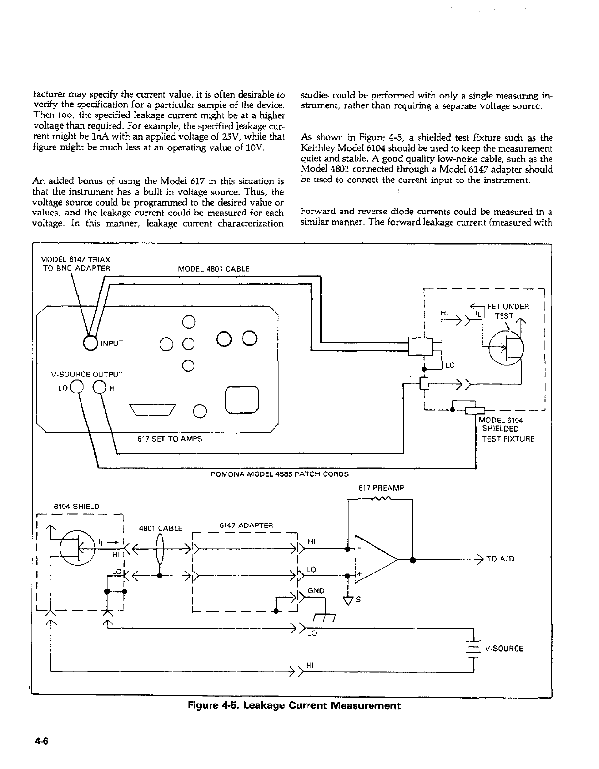
facturer may specify the current value, it is often desirable to
verify the specification for a particular sample of the device.
Then too, the specified leakage current might be at a higher
voltage than required. For example, the specified leakage current might be 11~4 with an applied voltage of 25V, while that
figure might be much less at an operating value of 1OV.
An added bonus of using the Model 617 in this situation is
that the instrument has a built in voltage source. Thus, the
voltage source could be programmed to the desired value or
values, and the leakage current could be measured for each
voltage. In this manner, leakage current characterization
MODEL 6147 TRIAX
TO BNC ADAPTER
MODEL 4801 CABLE
studies could be perfomed with only a single measuring in-
strument, rather than requiring a separate voltage source.
As shown in Figure 4-5, a shielded test fixture such as the
Keithley Model 6104 should be used to keep the measurement
quiet and stable. A good quality low-noise cable, such as the
Model 4801 connected through a Model 6147 adapter should
be used to connect the current input to the instnnnent.
Forward and reverse diode currents could be measured in a
similar manner. The forward leakage current (measured with
\ II
‘--Il.::
V-SOURCE OUTPUT
LO HI
\
6104 SHIELD
------
\ \
617 SET TO AMPS
\
\
0
0
/
POMONA MODEL 4686 PATCH CORDS
617 PREAMP
r-l
r----
--1
TEST FIXTURE
-~~~~~~~--AID
Figure 4-5. Leakage Current Measurement
>LO
-+>H’
1.
- V-SOURCE
T
Page 97
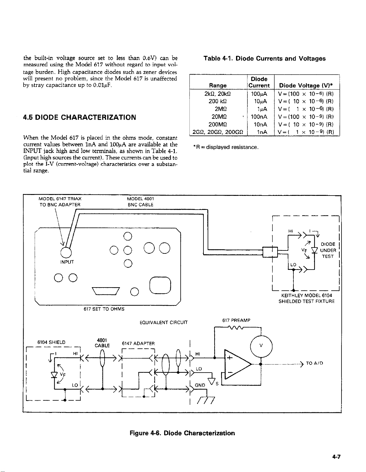
the built-in voltage source set to less than 0.6V) can be
measured using the Model 617 without regard to input voltage burden. High capacitance diodes such as zener devices
will present no problem, since the Model 617 is unaffected
by stray capacitance up to O.OlpF.
4.5 DIODE CHARACTERIZATION
When the Model 617 is placed in the ohms mode, constant
current values between In4 and lC@A are available at the
INPUT jack high and low terminals, as shown in Table 4-l.
(Input high sources the current). These currents can be used to
plot the I-V (current-voltage) characteristics over a substantial range.
Table 4-I. Diode Currents and Voltages
Diode
Range
2kQ. 20kfI
200 kCl
2MQ
ZOMR
200MQ
2GR, 20GQ, 200GD
*R = displayed resistance.
Current Diode Voltage (VP
lOOpA V=(lOO x 10-61 (f?)
lOpA V=( 10 x 10-q (RI
14
. lOOnA V=(lOO x 10-q (RI
1OnA V=( 10 x 10-q (RI
1nA V=( 1 x 10-?(R)
v=( 1 x 1041 (RI
MODEL 6147 TRIAX
TO BNC ADAPTER BNC CABLE
‘I
INPVT
MODEL 4601
0
00
617 SET TO OHMS
EQUIVALENT CIRCUIT
6104 SHlELD
r-1
617 PREAMP
r-----
l--L---i
KEITHLEY MODEL 6104
SHIELDED TEST FIXTURE
1
Figure 4-6. Diode Characterization
4-7
Page 98
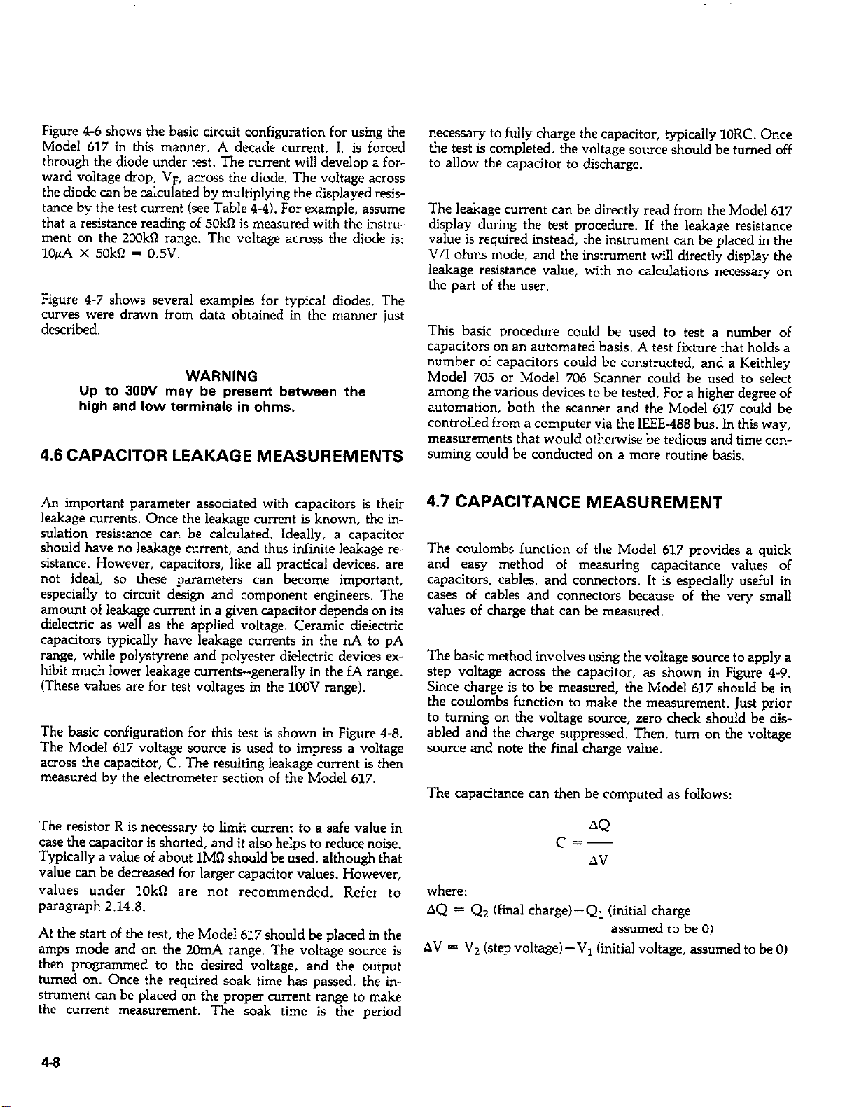
Figure 4-6 shows the basic circuit configuration for using the
Model 617 in this manner. A decade current, 1, is forced
through the diode under test. The current will develop a for-
ward voltage drop, VF, across the diode. The voltage across
the diode can be calculated by muldplying the displayed resis-
tance by the test current (see Table 4-4). For example, assume
that a resistance reading of 50kR is measured with the instru-
ment on the 2OOkR range. The voltage across the diode is:
lOpA X 50kR = 0.5V.
Figure 4-7 shows several examples for typical diodes. The
curves were drawn from data obtained in the manner just
described.
WARNING
Up to 300V may be present between the
high and low terminals in ohms.
4.6 CAPACITOR LEAKAGE MEASUREMENTS
necessary to folly charge the capacitor, typically 1ORC. Once
the test is completed, the voltage source should be turned off
to allow the capacitor to discharge.
The leakage current can be directly read from the Model 617
display during the test procedure. If the leakage resistance
value is required instead, the instrument can be placed in the
V/l ohms mode, and the instrument will directly display the
leakage resistance value, with no calculations necessary on
the part of the user.
This basic procedure could be used to test a number of
capacitors on an automated basis. A test fixture that holds a
number of capacitors could be constructed, and a Keithley
Model 705 or Model 706 Scanner could be used to select
among the various devices to be tested. For a higher degree of
automation, both the scanner and the Model 617 could be
controlled from a computer via the IEEE-488 bus. In this way,
measurements that would otherwise be tedious and time consuming could be conducted on a more routine basis.
An important parameter associated with capacitors is their
leakage currents. Once the leakage current is known, the insulation resistance can be calculated. Ideally, a capacitor
should have no leakage current, and thus infinite leakage resistance. However, capacitors, like all practical devices, are
not ideal, so these parameters can become important,
especially to circuit design and component engineers. The
amount of leakage current in a given capacitor depends on its
dielectric as well as the applied voltage. Ceramic dielectric
capacitors typically have leakage currents in the nA to pA
range, while polystyrene and polyester dielectric devices exhibit much lower leakage currents-generally in the fA range.
(These values are for test voltages in the 1COV range).
The basic configuration for this test is shown in Figure 4-8.
The Model 617 voltage source is used to impress a voltage
across the capacitor, C. The resulting leakage current is then
measured by the electrometer section of the Model 617.
The resistor R is necessary to limit current to a safe value in
case the capacitor is shorted, and it also helps to reduce noise.
Typically a value of about 1Mn should be used, although that
value can be decreased for larger capacitor values. However,
values under lOk0 are not recommended. Refer to
paragraph 2.14.8.
At the start of the test, the Model 617 should be placed in the
amps mode and on the 2011~4 range. The voltage source is
then programmed to the desired voltage, and the output
turned on. Once the required soak time has passed, the instrument can be placed on the proper current range to make
the current measurement. The soak time is the period
4.7 CAPACITANCE MEASUREMENT
The coulombs function of the Model 617 provides a quick
and easy method of measuring capacitance values of
capacitors, cables, and connectors. It is especially useful in
cases of cables and connectors because of the very small
values of charge that can be measured.
The basic method involves using the voltage source to apply a
step voltage across the capacitor, as shown in Figure 4-9.
Since charge is to be measured, the Model 617 should be in
the coulombs function to make the measuremenl. Just prior
to turning on the voltage source, zero check should be dis-
abled and the charge suppressed. Then, turn on the voltage
source and note the final charge value.
The capacitance can then be computed as follows:
AQ
cc-..-
AV
where:
AQ = Q2 (final charge)-Q1 (initial charge
assumed to be 0)
AV = V, (step voltage) -VI (initial voltage, assumed to be 0)
4-8
Page 99
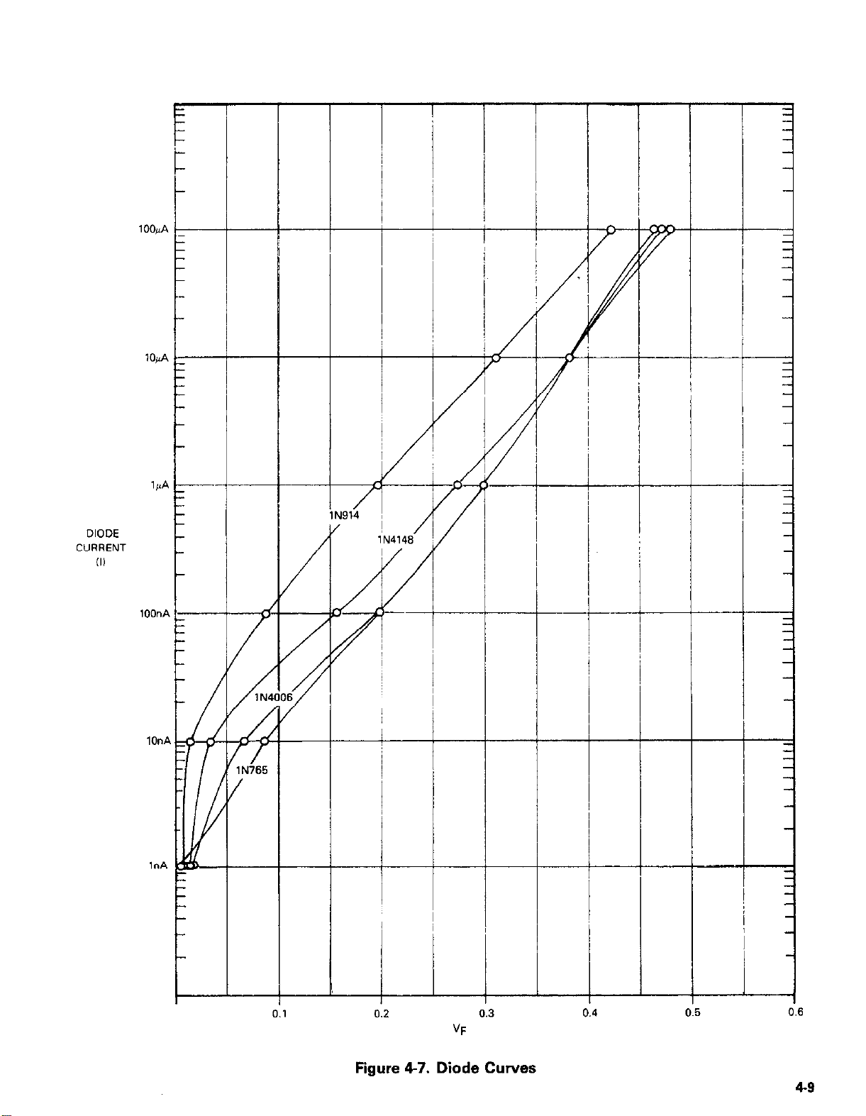
!-
,$‘A
DIODE
CVRRENT
(II
lOO”A -
L
-
#
---l--
0.2
-
0.6
Figure 4-7. Diode Curves
49
Page 100
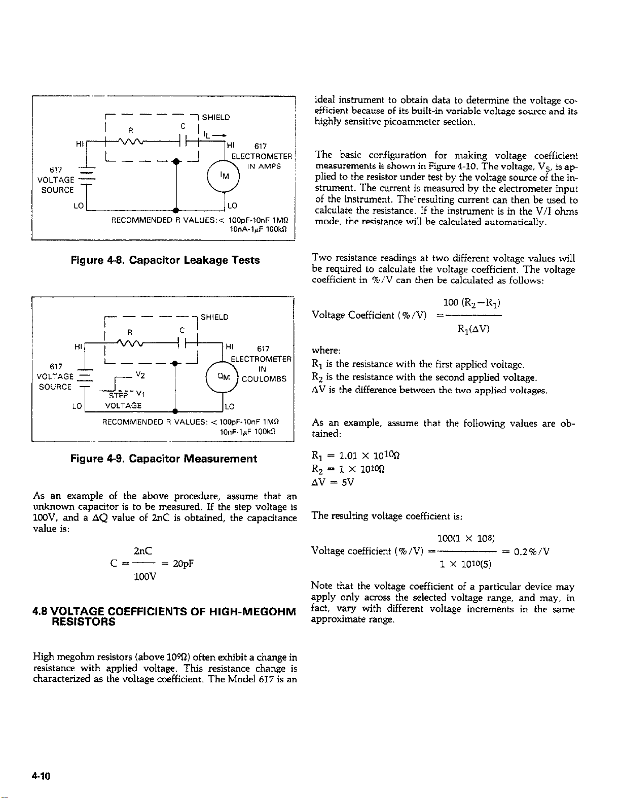
-.--!
T-- - - - - -, SHIELD
RECOMMENDED R VALUES:< IOOpF-10nF 1MR
IOnA-l+F 1OOkR
ideal instrument to obtain data to determine the voltage co-
efficient because of its built-in variable voltage source and its
I
highly sensitive picoammeter section.
The basic configuration for making voltage coefficient
measurements is shown in Figure 4-10. The voltage, Vs, is applied to the resistor under test by the voltage source of the instrument. The current is measured by the electrometer input
of the instrument. The! resulting current can then be used to
calculate the resistance. If the instrument is in the V/I ohms
mode, the resistance will be calculated automatically.
Figure 4-8. Capacitor Leakage Tests
RECOMMENDED R VALUES: < lOO,+lOnF IMR
Figure 4-9. Capacitor Measurement
As an example of the above procedure, assume that an
unknown capacitor is to be measured. If the step voltage is
1LXW. and a AQ value of 2°C is obtained, the capacitance
value is:
2°C
Cc---
4.8 VOLTAGE COEFFICIENTS OF HIGH-MEGOHM
RESISTORS
= 20pF
1OQv
,OnF.l,J 1OOkll
Two resistance readings at two different voltage values will
be required to calculate the voltage coefficient. The voltage
coefficient in %/V can then be calculated as follows:
100 CR,--R,)
Voltage Coefficient (%/V) =
R,(AV)
where:
R, is the resistance with the first applied voltage.
R, is the resistance with the second applied voltage.
AV is the difference between the two applied voltages.
As an example, assume that the following values are obtained:
R, = 1.01 x IOW
RZ = 1 x loWI
AV = 5V
The resulting voltage coefficient is:
X0(1 X 10⁸)
Voltage coefficient (%/VI =
1 x lolo
Note that the voltage coefficient of a particular device may
apply only across the selected voltage range, and may, in
fact, vary with different voltage increments in the same
approximate range.
= 0.2%/V
High megohm resistors (above 10%) often exhibit a change in
resistance with applied voltage. This resistance change is
characterized as the voltage coefficient. The Model 617 is an
4-10
 Loading...