

Page 1

INSTRUCTION MANUAL
MODEL
DIFFERENTIAL ELECTROMETER AMPLIFIER
604
KEITHLEY INSTRUMENTS, INC.
PRINTED JANUARY 1977, CLEVELAND, OHIO U.S.A.
Page 2

CONTENTS
MODEL 604
CONTENTS
Section
Page
SPECIFICATIONS ................................. iv
1. GENERAL DISCRIPTION.
2. OPERATION
..................................
............................
1
3
3. CIRCUIT DESCRIPTION. ............................ 11
4.
MAINTENANCE.................................1 3
5.
ACCESSORIES. ................................ 25
6. REPLACEABLE PARTS. ............................. 27
SCHEMATICS...................................3 6
ii
0177
Page 3
MODEL 604
ILLUSTRATIONS
ILLUSTRATIONS
Fig. No.
1 Model604FrontPanelControls
2
Model 604 Rear Panel Controls .................... 3
Title
....................
3 Model 6041 Front Panel. ....................... 4
4
TypicalExperiment
..........................
5 Error Due to Ammeter Resistance ................... 8
6 Internal View of Model 301 Amplifier.
7 Model 604 Block Diagram
.......................
................
Ripple Obtained for the 26 Volt Supply. ............... 14
:
Ripple Obtained for the 15 Volt Supply. ............... 15
10 Ripple Obtained for the 21 Volt Supply. ............... 15
11 Location of Voltage Supplies Test Points. .............. 15
12 Null Obtained with the Signal Generator at 5H.z. ........... 17
13
14 Top View Model 604.
15
Null Obtained with the Signal Generator at 1kHz ........... 17
.........................
Bottom View Model 604
........................
16 Component Layout of PC-165. ..................... 23
17
18
19
Resistor Locations on PC-165. .................... 24
Top Cover Assembly.
.........................
Bottom Cover Assembly ........................ 35
Page
3
5
9
11
21
22
35
0177
iii
Page 4

SPECIFICATIONS
MODEL 604
SPECIFICATIONS
iv
0177
Page 5

SECTION 1.
GENERAL DESCRIPTION
h. When used in conjunction with the Model 6041
Differential Current Shmt the Model 604 hecome* a
single-ended or differential picoameter. Singleendp and differential current measurement* from
lo- to 10-14
Also, high megohm resistors may be installed within
the Model 604 to allow shunt picoammeter operation.
AS an amplifier, the Model 604 will operate
a.
over a bandwidth from dc to 50 km or greater with
six select&l* 3-dB points from 30 kHz to 100 Hz.
Thus, the signal-to-noise ratio may-be optimized for
a particular application. The amplifier output furnishes 210 volts at 5 milliamperes single-ended.
The Electrometer Amplifier has an input re-
b.
sistance of greater than lOI4 ohms shunted by less
than 5 picofarads in the unguarded position, that
allows high impedance measurement to be made easily.
When in the guarded position the input impedance is
shunted by less than 1 picofarad.
LOW OffSet Current - 1855 than 2 x m-14 ampere
- tkimiaes zero offset with high source resistance
and permits maximum resolution when measuring cur-
rent.
A choice of outputs which can he used simul-
d.
taneously or *ingly is available. Each input of
the Model 604 has' a unity gain output, which has
*so omn acc"rac". This alloWS the Model 604 to be
used-& a prea&ifier with differential or digital
voltmeters for precise measurements. Also, these
outputs can he fed into an X-Y recorder for recording
data from high impedance sources. When desired, the
unity-gain outputs can be monitored for absolute
values while recordings are made from the amplifier
output.
e. All outputs are short-circuit proof, and output noise referred to the input is nearly constant
regardless of the gain.
The guarding capability of the Model 604 al-
f.
lows fast masurements from high resistance sources,
by eliminating the effects of cable capacitance and
leakaoe. TO convenientlv facilitate these measure-
ments, the Model 6301 Gu&ded Probe can be used to
connect the eonroe to the Model 604 in the guarded
mode. the guard feature is switch seleotable.
ampere can be made with this setup.
Mo%l 604 is its zero stability. signals can be
monitored over weeks without constant rezeroing.
volts per week; zero offset due to temperature changes is less than 300 microvolts per OC. Zero shift
A unique circuit provides protection while main-
&ides a very stable tl volt suppression on any
eliminated from the Model 604 output.
ent Shunt is an accessory specifically designed to
Noise will be as low as 2 x 10-15 anumre usins a
method limits the current span to only four decades,
Another outstanding feature of the Keitbler
Zero drift of the Amplifier is leas than 4 milli-
due to mechanical shock or vibration is negligible.
Overloads up to +4OO volts will not damage
h.
the 604 Amplifier, and recovery is almost immediate.
taining the favorable features of the MOS PET input.
AS another convenience feature, the Model 604
range.
l-volt signal can be displayed full scale.
volts cauee no apparent change even on the most sensitive range. Line frequency noise is practically
l-3.
convert the Model 504 Amplifier into a single-ended
or differential multi-range picometer.
fier and the Model 6041 Shunt combination to obtain
fast response in c*rrent measurexnente. Input capacitance at the end of a IO-foot cable is maintained
at 1 picofarad in the guarded mode. As a result,
risaltimes of 0.5 millisecond are possible with
lo- ampere input signals.
through the Model 6041 by the use of triaxial input
conneotors and total auardina within the Shunt
itself.
h.
to-noise ratio is more desirable than fast response,
the Model 604 can be used in its unguarded mode.
lOI ohm resistor.
longer than when the Model 604 is in its guarded
mode. Regardless of mode, the high frequency cutoff can be used to reduce noise at the higher frequencies .
is to he monitored, a pair of high megohm resis-
tors, available as the Model 6033, can be mounted
internally within the Model 604. Although this
it does slightly improve both the noise and the
rise time characteristics over that obtainabLe with
the multi-range Model 6041 Current Shunt.
promise between noise and rise time still must be
made by choosing the guarded or unguarded mode.
high source resistance, permitting maximum resolu-
tion when measuring current.
variations a5 small as 1 millivolt in a
j. Variations in line valtagee from 105 to 125
MODEL 6041. The Model 6041 Differential cur-
a. The driven guard enables the Model 604 Ampli-
Guarding is maintained
For those applicarions where maximum signal-
Hcwever, rise t&es are m&h
For those cases where a limited current span
C.
The cam-
d. Low offset cn~lent minimizes zem offset with
0373
Page 6

Varies the high frequency rolloff of the Model 604 and
selects the maximum bandwidth to be measured. When the
Switch is in the OFF Position the full handwidth of the
Model 604 is available.
Turns instrument off and on; disconnects meter; selects
meter polarity: sets instrument for center zero operation.
Indicates instrument is on.
2-2
2-8
2-6
t+, and c-, INPUT
Receptacles.
Control
UNITY GAIN O"TP"l3:
FROM c-j TNP"Ti FROM (+I
INPUT
GROUND Post
I
FUSE
I
shunts respective INPUT Receptacle. Locking either one
allows single ended use.
Opening both allows differential measurements,
connect inputs to sources. May be wed either singularly
or conjointly for single ended or differential measurements respectively.
triaxia1 COnrLectOTs.
Functional Description
For use as an extremely linear preamplifier. Outputs 2-11
are equal to respective inputs within *0.005% at dc,
exclusive of offset, noise and drift.
Connected to ground of all the outp"ts and the ground ---
wire of the power cord.
3x slow Blow.
117 volt operation: -l/8 ampere.
234 ""It nnaration: -,~/I~6 amnerc.
Locking both zeroes the meter.
Receptacles are Teflon-insulated
2-2
2-2
2-l
Paragraph
2-8
INPUT :
lo 604 INPUTS:
+ and -
GND
2
+ and -
Functional Description
switches shunt resistor at input of the amplifier
for the Model 604 +INPUT Receptacle, thus determining
full scale current range Model 604 is to measure.
Switches shunt resistor at input of the amplifier
for the Model 604 -INPUT Receptacle, thus determining
full scale current range Model 604 is to measure.
~0th switches are used in differential current measure-
Connects Model 6041 inputs to BOUTCBS. May be used either 2-2
singularly or conjointly for single-ended or differential
measurements respectively.
insulated triaxial connectors.
Connects Model 6041 to respective Model 604 Input Recep-
tac1es.
connected to ground of Models 604 and 6041
Receptacles are Teflon-
Paragraph
2-2
2-2
2-2
0373
Page 7
SECTION 2.
OPERATION
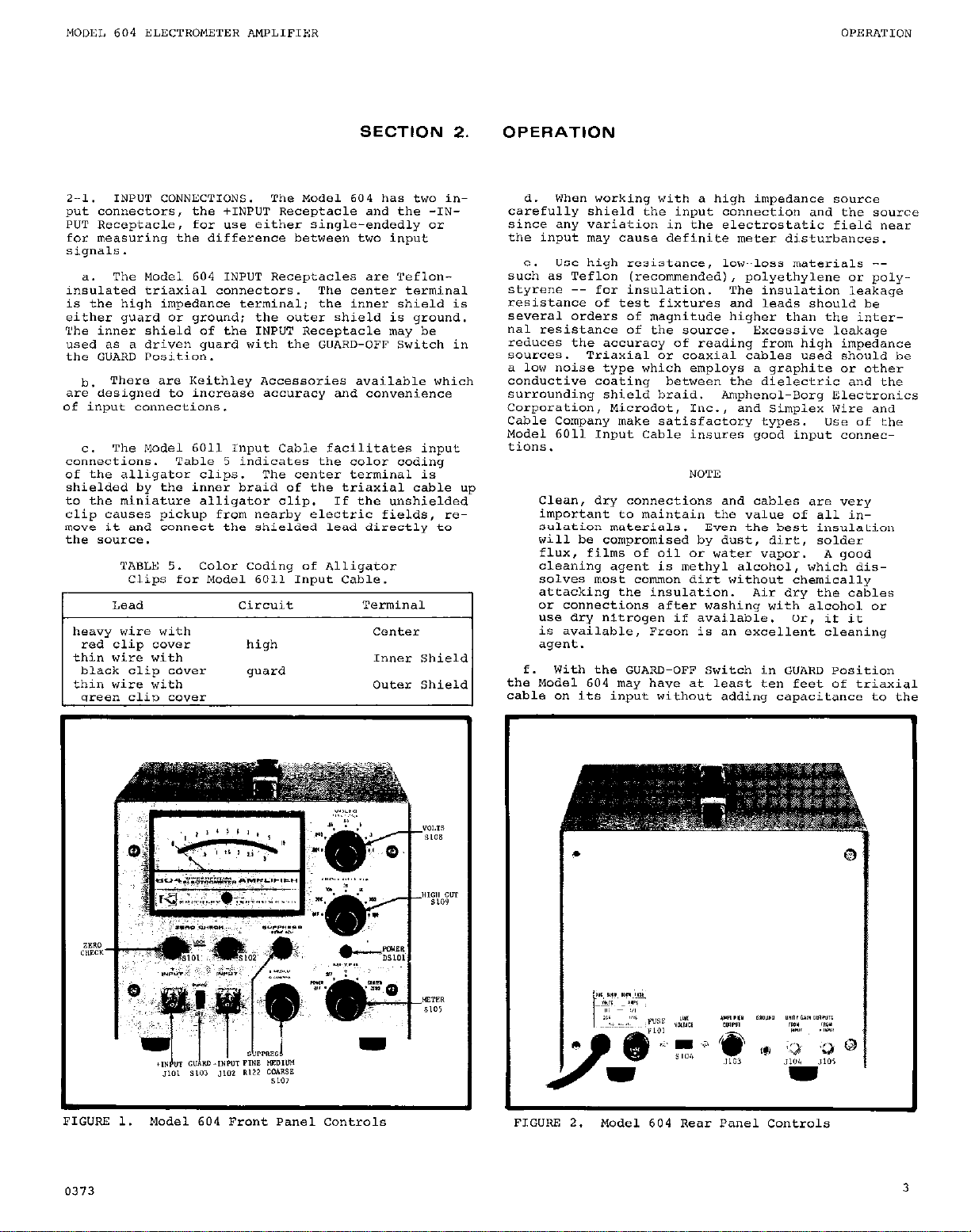
2-l. INPUT CONNECTIONS.
put connectors, the +1NFUT receptacle and the -INPUT Receptacle, for use either single-endedly or
for measuring the difference between two input
signals.
a. The Model 604 INPUT Receptacles are Tefloninsulated triaxial connectors.
is the high impedance terminal; the inner shield is
either guard or ground; the outer shield is ground.
The inner shield of the INPUT Receptacle may he
used as a driven guard with the GUARD-OFF Switch in
the GUARD Position.
h. There arc Keithley Accessories available which
are designed to lnclease accuracy and co""e"ie"ce
of input connections.
C.
The Model 6011 Input Cable facilitates input
connections. Table 5 indicates the color coding
of the alligator clips. The center terminal is
shielded by the inner braid of the triaxial cable up
to the miniature alligator clip.
clip causes pickup from nearby electric fields, re-
move it and connect the shielded lead directly to
the source.
I
Lead
heavy wire with
red clip cover
thin wire with Inner Shield
black clip cover guard
thin wire with Outer Shield
"7%-P" rlin rn.lP?
The Model 604 has two in-
The center terminal
If the unshielded
circuit Terminal
center
high
d. When working with a high impedance source
carefully shield the input connection and the source
since any variation in the electrostatic field near
the input may cause definite meter disturbances.
Use high resistance, low-loss materials -s":h as Teflon (recommended,, polyethylene or polystyrene -- for insulation. The insulation leakage
resistance of test fixtures and leads should be
several orders of magnitude higher than the inter-
nal resistance of the source. Excessive leakage
reduces the accuracy of reading from high impedance
sources. Triaxial or coaxial cables used should be
a low noise type which employs a graphite or other
conductive coating between the dielectric and the
surrounding shield braid. Amphenol-Borg Electronics
Corporation, Microdot, Inc., and Simplex Wire and
Cable Company make satisfactory types. use of the
Model 6011 Input Cable insures good input connections.
NOTI?
Clean, dry connections and cables are very
important to maintain the value of all insulation materials. Even the best insulation
will be compromised by dust, dirt, solder
flux, films of oil 01 water vapor. A good
cleaning agent is methyl alcohol, which dissolves most commm dirt without chemically
attacking the insulation. Air dry the cables
I
or connections after washing with alcohol or
use dry nitrogen if available. Or, if it
is available, Freon is an excellent cleaning
agent.
f.
With the GUARD-OFF Switch in GUARD Position
the Model 604 may have at least ten feet of triaxial
cable on its input without adding capacitance to the
FI
0373
3
Page 8

input (input capacitance is specified at 1 pF).
Note, hwever, that guarding can only eliminate input cable capacitance effects.
ial case, see subparagraph S-Ii, guarding cannot be
Except in one spec-
used to eliminate effects due to source capacitance.
DO not connect the guard circuit to the source.
--__-
__--.~
NOTE
For a complete discussion on guarding with
the Model 604 refer to paragraphs 2-3 and
2-4.
When working with a high impedance source any
4.
change in the shunt capacitance of the input circuit will cause disturbances in the reading. Make
the measuring setup as rigid as possible, and tie
down connecting cables to prevent their movement.
A continuous vibration may appear at the output as
a sinusoidal signal, and other precautions may be
necessary to isolate the instrument and the connecting cable from the vibration.
For low impedance measuremen~s~-- measurements
h.
that are above 10-8 ampere -- ""shielded leads may
ae usea.
The Model 6012 Triaxial-to-Coaxial Adapter
enkles using coaxial cables and accessories with
the Model 604 by adapting the triaxiol INPUT ~eceptacles to the UHF coaxial type.
The Adapter connects the Model 604 inner
1.
shield to ground defeating the guard capability
that the triaxial receptacles make possible. EXcept for the special case spelled out in the following subparagraph 2, the GUARD-OFF Switch must
be in the OFF position for the instrument to function
2. If the Model 6012 Adapter is used with the
Model 6041 Shunt in front of the Model 604 and
the current souroe can be floated off ground, then
a feedback picoameter connection is possible.
In this situation the coaxial shield is guard
with the GUARD-OFF Switch in the GUARD position.
TO make possible a guarded circuit, connect guard,
the coaxial shield, to the low of the current
SOUlCe. Remember, however, if the current source
low is grounded, the GUARD-OFF Switch must be in
the OFF position for the instrument to operate,
and no guarded circuit is possible this way.
a. The Model 604 + INPUT Receptacle is the input
to the non-inverting amplifier.
This means that
for a single-ended positive input to this Receptacle
the output is positive and for a negative input the
output is negative. The polarity can also be interpreted with the METER Switch and displayed on the
meter.
b. The Model 604 - INPUT Receptacle is the input
to the inverting amplifier.
ended positive input signal to this Receptacle the
Thus for a single-
output is negative and for a negative input the
output is positive.
For single-ended measurements just lock the
C.
ZERO CHECK Button for the Input Receptacle that you
do not intend to me, and apply the signal to the
other Receptacle. When locked, the ZERO CHECK But-
ton will connect its Input Receptacle to ground presenting an open circuit to the respective amplifier.
The Model 604 always measures the signal differentially.
difference between the applied signal and the ref-
In the single-ended mode it measures the
erence signal (ground).
L
F: LG”Rr! 3.
d.
CHECK Buttons and apply one signal to one of the Input Receptacles and the other sianal to the other
Kecepta&.
accepts the high or low signal.
the -INPUT Receptacle is positive with respect to
Model 6041 Front Panel Controls and
For differential measurements unlock both ZERO
It does not matter ;hich Receptacle
If the signal to
the signal to the +INPUT Receptacle, then the output,
and the meter, will read negative.
to the +IINPUT Receptacle is positive with respect
to the signal to the -INPUT Receptacle, then the
If the signal
output will be positive.
whpch, when used in conjunction with the Model 604,
enables the Model 604 to become either a singleended or differential shunt ammeter.
The Model 6041 'is a Differential Current Shunt
ceptacles on the Model 6041 are nominally labeled.
The INPUT ne-
That is, it is not essential that, single-endedly,
a positive signal be applied to the C+) Receptacle
and a negative to the (-) Receptacle or, differentially, the high signal to the (+I and the low to
the (-).
1.
The Model 6041 outputs (labeled: TO 604
INPUTS; + and -,,
the Model 604, are directly tied to their correspending Input Receptacle.
the +INPUT Receptacle will be accepted at the +
which connect the Model 6041 to
That is, a signal to
output and a signal to the -TNPUT Receptacle will
be accepted at the - output.
2. Though it is not absolutely necessary, it
is recommended that upon connecting the Model
6041 to the Model 604, the corresponding output
receptacle of the Model 6041 be connected to the
corresponding Input Receptacle on the Model 604.
Otherwise, the user may become utterly confused
at what the polarity at the Model 604 output
corresponds to.
3. Note that the +INPUT Switch on the Model
6041 applies to the Model 6041 +INPUT Receptacle
only and the -INPUT switch applies to the -INPUT
Receptacle only, regardless of the relative or
absolute polarities of the signals at the inputs.
4
0373
Page 9

2-3. GUARDING.
a. There are several factors which contribute to
the bandwidth of an experiment.
1. The amplifier bandwidth;
2. The so"rce resistance and capacitance;
3.
The capacitance of the cable connecting
amplifier to the source.
f3dB =
So, in this example, connecting the source to the
amplifier with a 3 foot cable, withcut guarding,
would cause a IO:1 reduction in bandwidth.
The Model 604 is designed to eliminate (guard)
thz'cable capacitance when used in the guard mode.
The Model 604 will reduce the apparent capacity at
the end of an up to 10 foot long triaxial cable to
approximately 1 picofarad by driving the inner
shield of the cable.
10~~10+90) (10-l')
.16
= 1.6 iiz
Model 604
GLw.E 4.
g the Amplifier, Cable and Source.
is the capacitance due to the connecting cable,
is the source capacitance,
stance and ES is the source voltage.
b. In the typical setup shown in Figure 4, if a
perfect amplifier were placed at the source,the 3 dD
frequency of the so"rce would be
f3dB =
where f3du is the 3dB bandwidth of the source in HZ:
1. If, to take an example, Rs is equal to lo9
ohms and Cs is equal to 10 picofarads, then
2. NOW, if a cable is used to connect the so"rce
to the amplifier, a new bandwidth is encountered
because of the addition of the cable capacitance
and equation 1 becomes
f3dB =
where $$B
An average cable adds approximately 30 picofarads
per foot to the circuit. Th"s, a 3-foot cable
would add 90 picofarads and
Figure Depicts a Typical Experiment Show-
KS is the source re-
&I$ cs = .M& cs
R, is the ~o"rce resistance in ohms.
and Cs is the so"rce capacitance in farads.
.16 equation 2
Rs (c,+c,)
is the 3d0 bandwidth of the system in
R,'is the source resistance in ohms;
Cs is the source capacitance in farads;
=*d Cc is the cable CaDacitance in farads.
In the figure
equation 1.
The capacity from the center conductor of a
triaxial cable to the inner shield is about
30 picofarads per foot. From the inner shield
to the outer shield it is about 70 picofarads
per foot, The signal source, however, only
sees the capacity from the center conductor
to the inner shield. The guard circuit,
though, drives the entire capacity, about
100 picofarads per foot. The yodel 604 guard
circuit effectively drives up to 1000 picofarads; th"s the 10 foot cable limitation.
1.
ture of the Model 604 allows the user to achieve
almost the entire bandwidth of the so"rce circuit.
does not increase the bandwidth of the so"rce, but
$xf.y;ically eliminates the effect of cable cap-
d.
limitations.
picofarads. Thus, no more than 1000 picofarads
should be guarded from either input for optimum
response.
common mode voltage swing (tll volts dc to 1 kliz
and approximately 22 volts at 5 !a~).
5 kllz because of internal phase shifts.
shifts cause peaking to occur above 5 kHz, but
the system still remains stable.
e.
own separate guard circuit which is completely independent of the other. Note, also, that guard and
the unity-gain 0"tp"ts are electronically identical
(see schematic diagram 228201: in Section5 ).
2-4.
a. This Switch when in the GUARD Position reduces
the effect of input cable capacity and provides
high speed measurements from high resistance so"rces
at the end of a cable by driving the cable capacitance and the inner shield of the INPUT Rece~tacle(s) (refer to paragraph 2-3). h guarded ckuit
is possible in this way.
b. With the Switch in the GUARD Position input
capacity is decreased (to approximately 1 pi even
with "p to 10 feet of cable on the input) and rise
time is decreased. Note, however, that the noise
is increased.
In the above example, then, the guard fea-
f
3dB =
2. Notice that, in the above case, guarding
The guard feature does, however, have several
1.
2. The guard voltage swing is limited by the
3.
Note that each input of the Model 604 has its
GUARD-OFF SWITCH.
lo~(lo+l) (lolr)
It is effective driving only up to 1000
The guard feature is not effective beyond
.16 = 14.1 LIZ.
These
0373
5
Page 10
the input capaoity is increased to 5 pF with no
cable
on the input.
are decreased.
d. Therefore, although guarding increases speed,
it also increases noise as well and a oompromise
between speed and noise will have to be made.
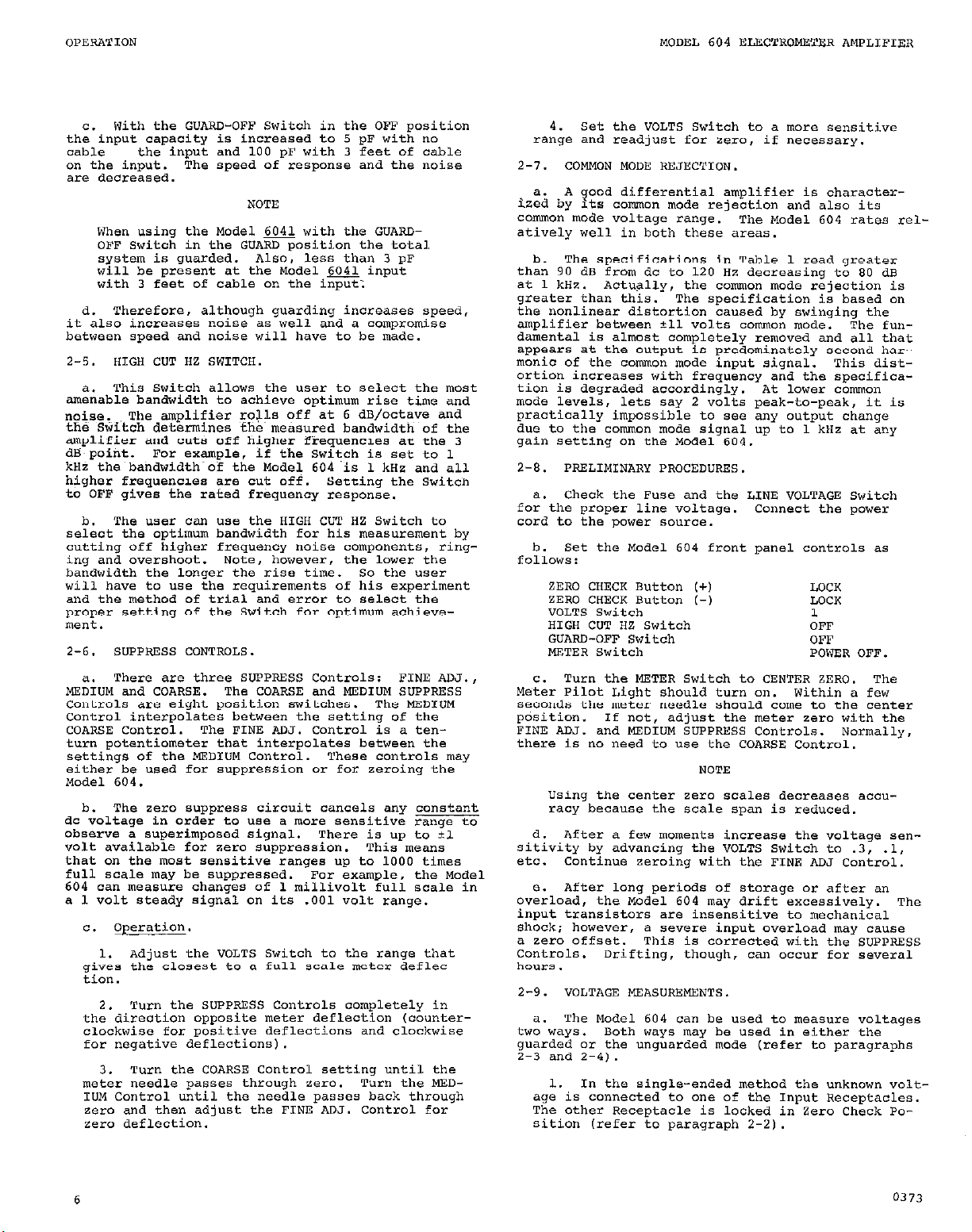
a. This Switch allows the user to select the most
amenable bandwidth to achieve optimum rise time and
noise
the S&itch determines fhe meGured bandwidth of the
amplifier and cuts off higher f&quenc~ea a+ the 3
dEi point. For example, if the Switch is set to 1
kHz the~bahdwidth~of the Model 604 is 1 ~HZ and all
higher frequencies are cut off. Setting the Switch
to OFF gives the rated frequency response.
b.
select the optimum bandwidth for his measurement by
cutting off higher frequency noise components, ringing and overshoot.
bandwidth the longer the rise time.
will have to use the reguirements of his experiment
and the method of trial and error to select the
proper setting of the Switch for optimum achieve-
ment.
2-6.
ME,";,ld
Controls are eight position switches. The MEDIUM
control interpolates between the setting of the
COARSE Control.
turn potentiometer that interpolates between the
settings of the MEDIUM Control.
either be used for suppression or for zeroing the
Model 604.
b. The zero suppress circuit cancels any constant
dc voltage in order to use a more sensitive range to
observe a superimposed signal. There is up to 11
volt available for zero suppression. This means
that on the most sensitive ranges up to 1000 times
full scale may be suppressed.
604 can measure changes of 1 millivolt full scale in
a 1 volt steady signal on its .OO1 wit range.
C. operation.
c,:,;~ the closest to a full scale meter deflec-
the direotion opposite meter deflection (counterclookwise for positive deflections and clockwise
for negative deflections).
meter needle passes through zero.
IUM Control until the needle passes back through
zero and then adjust the FINE ADJ. Control for
zero deflection.
the input and 100 pF with 3 feet of cable
The speed of response and the noise
When using the Model 6041 with the GUARDOFF Switch in the GUARD position the total
system is guarded. Also, less than 3 pF
will be present at the Madel,~ input
with 3 feet of cable on the Input:
The amplifier ro+ off at 6 dB/octave and
The user oan use the HIGH CUT HZ Switch to
Note, however, the lower the
SUPPRESS CONTROLS. METER Switch
There are three SUPPRESS Controls:
and COARSE.
1. Adjust the VOLTS Switch to the range that
Turn the SUPPRESS Controls completely in
2.
turn the COARSE Control setting until the
3.
The COARSE and MEDIUM SUPPRESS
The FINE ADJ. Control is a ten-
For example, the Model
So the "ser
Fnm ALU.,
These controls may
Turn the MED-
With the GUARD-OFF switch in the OFF position
C.
4. Set the VOLTS Switch to a more sensitive
range and readjust for zero, if necessary.
a. A good differential amplifier is characterized by Its common mode rejection and also its
common mode voltage range.
atively well in both these areas.
b. The specifications in Table 1 read greater
than 90 dB from dc to 120 HZ decreasing to 80 dB
at 1 kHz.
greater than this.
the nonlinear distortion caused by swinging the
amplifier between i-11 volts comon mode.
damental is almost completely removed and all
appears at the output is predominately second bar-
manic of the cornon mode input signal. This distortion inoreases with frequency and the specifica-
tion is degraded acoordinyly. At lower ~mnmn
mode levels, lets say 2 volts peak-to-peak, it is
practically impossible to see any output change
due to the common mode signal up to 1 kHz at any
gain setting on the Model 604.
a. Check the Fuse and the LINE VOLTAGE Switch
for the proper line voltage. Connect the power
cord to the power source.
GUARD-OFF Switch OFF
C. Turn the METER Switch to CENTER ZERO. The
Meter Pilot Light should turn an. Within a few
seconds the meter needle should come to the
position.
FINE AN. and MEDIUM SUPPRESS Controls. Normall".
there is no need to use the COARSE Control.
Using the center zero scales decreases accuraoy because the scale span is reduced.
d. After a few moments increase the voltage sensitivity by advancing the VOLTS Switch to .3, .1,
etc.
e. After long periods of storage or after an
overload, the Model 604 may drift excessively.
input transistors are insensitive to mechanical
shock; however, a severe input overload may cause
a zero offset.
Controls.
ho"rS
2-Y. VOLTAGE MEASUREMENTS.
tW:'WayS.
guarded or the unguarded mode (refer to ,,aragraphs
2-3 and 2-4).
1. In the single-ended method the unknown volt-
age is connected to one of the Input Receptacles.
The other Receptacle is locked in Zero Check Po-
sition Irefer to paragraph 2-2).
Actually, the comm mode rejection is
The specification is based on
If not, adjust the meter zero with the
Continue zeroing with the FINE ADJ Control.
This is corrected with the SUPPRESS
Drifting, though, can occur far several
The Model 604 can be used to measure voltages
Both ways may be used in either the
The Model 604 rates re1-
POWER OFF.
NOTE
The fun-
that
center
.
The
6
0373
Page 11

NOTE
The ZERO CHECK Buttons are tr”e transfer
type switches.
the input will be briefly connected to
lo9
ohms to ground.
are further depressed toward LOCK position the input is open circuited and will
remain so until the B"tto" is released.
I" the LOCK position the Model 504 input
is internally connected to ground.
note that for certain very high impedance
sources it may be necessary t" "ever con-
nect the i"p"t to ground, eve" through
109 ohms.
and release the ZERO CHECK Button as
fast as possible and the source will see
109 ohms for only a few milliseconds.
In the differential method one ""know" "olt-
2.
age is connected to one of the Input Receptacles
and the other voltage is connected to the other
Input Receptacle.
ButtonS are unlocked.
ACC~SSCX-y probes extend the Model 604's
3.
range to 10 kilovolts. (Use either single-endedly
or differentially only with the GUARD-OFF Switch
in the OFF position).
b. Single-Ended Method Voltage Measurements.
This method should be used when an unknown voltage
from a single source is to be measured.
paragraph 2-2 also).
set the Model 604 front pane1 Controls as
1.
follo"s:
connect the unknown voltage to one of the
2.
Input Receptacles.
and ""lock the ZERO CHECK Button pertaining to
tile used Input Receptacle.
CHECK Button in the LOCK position.
witch to + or -, as necessary. Increase sensitivity with the VOLTS switch until the greatest
on-scale meter deflection is obtained.
zero setting after increasing sensitivity.
fer to paragraph 2-2 also).
For guarded, fast r"easure,"e"ts, set the
3.
GUARD-OFF Switch to GUARD.
the effects of input cable capacity with very
high impedance sources and allouis guarded voltage
measurements (Refer to paragraphs 2-3 and Z-4).
set the HIGH CUT HZ Switch to the desired
4.
position to obtain optimun response.
paragraph Z-5).
Differential Method Voltage Measurements.
T.;, method should be used to ",eas"re the difference
between two ""know" voltages "either of which has
to be at ground potential, and either of which may
be as much as 211 volts off ground.
graph 2-Z).
Set the Model 604 front panel controls as
1.
show" in subparagraph bl above.
connect one unknown voltage to one Of the
2.
input receptacles and the &her "oltage to the
other 1npLlt Receptacle.
When they are depressed,
Then as the L3uttons
Please
1f this is the case, depress
I" this mode both ZERO CHECK
(Refer to paragraph Z-2).
Zero the meter (paragraph 2-6,
Keep the other ZERO
Set the METER
This method reduces
(Refer to
(Refer to para-
zero the meter and the"
(Refer to
Recheck
CR*-
""lock both ZERO CAECK Buttons.
Switch to + or -, as necessary. Increase sensitivity with the VOLTS Switch until the greatest
o" scale meter deflection is obtained.
7.ero settina after increasinil sensitivitv. me
difference Gig"& is equal to the perce";age of
full scale that the mete* reads times the VOYPS
switch setting. (Refer to paragraph 2-2 also).
3. For guarded, fast IneasureInents, set the
GUARD-OFF Switch to GUARD.
2-3 and 2-4).
4. Set the HIGA CUT HZ switch to the desired
position to obtain "ptimum response.
paragraph 2-5)
TO tneaS"re sollrces greater than 1 Volt, use
d.
one of two divider probes.
Divider Pr*be extends the Model 604's range to 10
volts' overall accuracy is i48 and input resistance
is 1Oio ohms. The Model 6103. 1OOO:l Divider Probe
extends the ?.,odel 604's range to 1 kilovolt; overall accuracy is 26% and input resistance is 1012
ohms. Follow the same operating procedures with
the dividers as in subparagraph b.
Triaxial-to-coaxial Adapter must be used with the
~"dels 6102A and 6103A Divider Probes.
ever, "sing the Adapter connects the inner shield
to ground, defeating the g"ardi"g capability of
the Model 604. Th*r*fOre,
rnu~t be in the OFF position for the instrument to
operate. The full-scale voltage range is the divider ratio times the VOLTS Switch setting.
If the Models 6102~ and 6103A Divider Probes
are used with the Model 604 in the differential mode, the comm"" mode rejection is limited by the probe matching and typically weld
be about 30 dU. Thus,
mode voltage would cause a full scale indica
tion.
Z-10. CURRENT MEASURl?MENTS.
an ammeter when used in conjunction with the Model
6041 Differential C"rre"t Shunt or when resistors
are installed within the cases of the Model 301 (see
Figure 61. When using the Model 6041, resistors
are switched across the inputs of the Model 301
Amplifiers in the Model 604 with the + and - INPUT
Switches on the Model 6041.
range is equal to reciprocal of the INPUT Switch
setting on the Model 6041 times the setting of the
VOLTS Switch on the Model 604.
the INPUT Switch is set to lOa and the VOLTS switch
is set to .Ol, the" the full scale cwrent range
is equal to l/108 x .Ol = 10-B x .Ol = 10-10 amp-
eres.
The Model 301 Instruction Manual, SUpplied The Model 301 Instruction Manual, SUpplied
with the Model 604, gives complete informa- with the Model 604, gives complete informa-
tion on Model 301 operation, circuit descrip- tion on Model 301 operation, circuit description, troubleshooting, calibration, parts tion, troubleshooting, calibration, parts
lists and schematic diagrams. There are lists and schematic diagrams. There are
two Model 301 Operational Amplifiers used two Model 301 Operational Amplifiers used
as plug-i" ""its in the Model 604. as plug-i" ""its in the Model 604.
a. the Model 604 can measure curlent~ several
ways. each of which may be used either in the guard-
ed or ""guarded mode.
1. I" the single-ended method the ""know" current is connected to one of the 1"p"t Receptacles
03 the Model 6041. The other I"p"t Receptacle on
the Model 6041 is locked in Zero Check position
The Model 6102A 10:1
the GUARD-OFF Switch
NOTE
30 Volts of common
set the rnTER
Recheck
(Refer to paragraphs
(Refer to
The Model 6012
Note, how-
The Model 604 becomes
The full scale current
For example, if
0373
7
Page 12

by its corresponding ZERO CllECK Button on the
Model 604 front panel.
I" the differential method one unknown cur-
2.
rent is connected to one of the Input Receptacles
on the Model 6041 and the other current is connected to the other Input Receptacle. In this
mode both ZERO CHECK Buttons are ""locked.
fer to paragraph Z-2).
With the shunt resistors mounted inside the
3.
cases of the Model 301 Amplifiers in the Model 604
the Model 604 may be used as an anuneter either
single-endedly or differentially. This method,
however, limits versatility and gives only four
decades of response.
tions apply with this method as spelled out in
,,aragraph 2-2.
When resistors are mounted internally, the
input is open circuited when in zer" check.
This presents a" open circuit to the current source, stopping CUrrent flow. I"
some cases this could be harmful to the
current source and possibly to the Model
604 itself when high complicance voltages
are encountered.
(Refer to paragraph 2-2).
CR*-
The same input considera-
CAUTION
range, the input capacity and the method used
(guarded or unguarded). See specifications, Table
1, page ii. On all ranges, the rise time in the
guarded method is less than one second with the specified capacity across the input. Even with much
larger capacities on the input the negative feedback
maintains a relatively short rise time. Given a
choice, it is better to place the Model 6041 nearer
to the CUrrent source than to the data readinq instrulnent. Transmitting the input signal through
long cables decreases the responses speed and in-
creases noise.
MC&l 6041. This method is used to measure an "nknown current from a single source (Refer to paragraph 2-2).
Single-Ended Method Current Measurements with
Connect the Model 6041 Outputs, labeled TO
1.
604 INPUT + and -, to the corresponding Input
Receptacles on the Model 604 with the supplied
mating cable.
pane1 controls as follows:
Set the Model 604 and 6041 front
when making measurements from high impedance
sources or low current sources usinq the
guarding feature, it may be desireable to
set the HIGH CUT HZ Switch to the lowest
setting, 100 HZ, to limit the noise bandwidth in some ca6es'.
when guarding, increases linearity with
the bandwidth increase and the noise may
eventually overload the amplifier. This
would cause a" error in a meter reading,
but the error would go undetected ""less
the o"tp"t was monitored o" an oscilloscope.
Rise time varies primarily with the c"rre"t
b.
The noise increase.
LB------------
2. Connect the unknown current to one of the
input Receptacles on the Model 6041.
meter and unlock the ZERO CHECK Button that CDTresponds to the Input Receptacle being used. Set
the METER switch to + or -, as necessary. Increate sensitivity with the VOLTS Switch and the
Input Switch that corresponds to the Input Receptacle beinq used until the qreatest on-scale
meter deflection is obtained. Recheck zero setting after increasing sensitivity.
paragraph 2-2 also).
The full-scale c"rrent range is the VOLTS
3.
measuring point
‘70 error in reading due to circuit loading = -100
it Rin (< R, I a I meter and 9b error E 0
zero the
(Refer to
it!,
FIGURE 5. Error due to Ammeter Resistance. Current sources may be considered a voltage (E) in series with
a resistance (R). The current with the ammeter short circuited is I = E/R. With the Short circuit removed,
the effective i"p"t resistance of the ammeter (Ri") is in series with the source resistance (R). The current of the complete circ"it is reduced and Imeter = E/(R+Ri").
is small compared to R, Imeter
8
N I and the error introduced by circuit loading is negligible.
If the effective ammeter input resistance
0373
Page 13

Switch setting times the reciprocal of the Input Switch setting. use the Smallest VOLTS
Switch setting possible to minimize input voltage drop and thus obtain the best accuracy. The
full scale input voltage drop is equal to the
VOLTS Switch setting.
(Far example: If a currenf2sourae has a
300 Volt compliance and 10 ohms OutpUt
resistance, then I = 300/101z = 3 x 10m10
ampere. Using a lo9 ohms shunt resistor
and a 300 millivolt full scale voltage
range would display this current full
scale. The loading error would he only
O.l%, which is 40 times less than the
accuracy of the system. The signal-to-
noise ratio would be 100 times better
than if a 107 ohms shunt resistor and
a 3 millivolt full scale range were
used, .
d. Differential. Method Current Measurements with
the Model 6041. This meth*d is used to measure the
difference between two unknown currents neither of
Which has to he at ground. (Refer to paragraph 2-2 Each Mode:
also).
1.
Connect the Model 6041 outputs, labe?lad TO
604 DWJTS + and -, to the respective Input R&ceptacles on the Model 604 with the supplied mat- -INPUT Receptac:
ing cable. set the Models 604 and 6041 front panel COntrOlS as follows:
toe, Model 301 c
single-ended COI
panding to the
verting mode ant
34 Input Receptacle is connected
rational Amplifier hooked up in
pration.
XJT Receptacle is in a non-inne Amplifier corresponding
is in an inverting mode. If so
The Amplifier corres-
to
the
0373
IGURE 6.
01 Amplifier Showing Location
31 Installing Internal Resistor.
or complete and comprehensive
nfomation on the Model 301. re?I?
to
nstruction
internal View of Model
the supplied Model 3oi
Manual.
9
Page 14

TWLE 6.
shunt Resistors ~"ternally Mounted.
permissable to obtain the rise times.
to the signal bandwidth.
Shunt
Resistor
(ohms,
:$
1010
1011
Typical Rise Times and Noise of the Model 604 As A" Ammeter With a Single Pair of Model 6033
current
span
,fUll scale)
~__
10-6 to lo-9 A
10-S to 10-11 A
10-10 to 10-13 A
10-11 to 10-14 A
This table was compiled using the smallest HIGS CUT LIZ Switch setting
Thus, the noise bandwidth of the system is kept as close as possible
100 pF Guarded
Rise Time
lo%-90%
0.00003 set
0.0003 set
0.03 set
0.3 set
Noise
P-P
10-9 A
10-10 A
100 pF ""guarded
~~~"-,~p"
0.0003 se=
0.03 s-y
3.0 set
30.0 set
Noise
P-P
10-F A
10-U A
desired, the Model 604 may be used as a" ammeter
by installing shunt resistors within the cases of
either or both Model 301 Amplifiers.
the positions in which the internal resistors may
be mounted.
NOTE
When measuring current with the internally
mounted Keithley Model 6033
the Model 604 has slightly shorter rise times
and lower noise for corresponding Model 6041
ranges.
1. I" this configuration, therefore, the Model
6041 Current Shunt does not have to be used with
the Model 604 to make current "wasurements.
however. that installing the resistor* within the
Model 301 asses is a time consuming operation.
Note, also that using the Model 604 in such a ma""er severely limits the versatility and capahil-
ity of the Model 604.
meter in such a way allows only four decades of
current measuring capability.
The Mcdel 604 may be used to measure voltages
with the resistors installed within the
Amplifier*.
tude of the input impedance would the" be
equal to the value of the installed resistor. This could lead to significant errore
in voltage measurements if the source resistance is on the order of magnithde of the
installed resistor.
2. The Model 604 may be used aa either a
single-ended or differential current measuring
device in this configuration.
tions given in paragraph c and d above, less the
Model 6041 instructions, apply here for the
single-ended and differential modes respectively.
The full scale current range, or difference sig"al, is equal Co the reciprocal of the shunt
resistcr times the setting of the VOLTS Switch.
(Refer to paragraph 2-2 also,.
Pay special attention to the caution of
paragraph 2-10.3, sub-paragraph 3.
f. Use the GUARD-OFF Switch for Guarded or ung"arded Measurements. Guarded or ""guarded measurements can be made in each of the preceeding
modes.
g. Use the HIGS CUT HZ Switch in each of the
current moded as desired to obtain optimum response.
(Refer to paragraph 2-5).
Please refer to Table 6.
&lso, using it as a" am-
Note, however, that the magni-
CAUTION
(Refer to w.ragra@,s 2-3 and 2-4 also,
Shunt
Figure 6 shows
Resistors,
Note,
The same instruc-
two UNITY GAIN OUTPUTS each corresponding to its
respective Input Receptacle, Providing signals
equal to each input-to-ground voltage to within
10.005% at dc; a" AMPLIFIER OUTPUT for recordina
the amplified or difference signal.
may be used to drive recorders, oscilloscopes and
X and Y recorders to record amplified signals, dif-
ference signals and absolute signals.
NOTE
The front panel SUPPRESS Controls will zero
only the FROM +INP"T GAIN OUTPUT: that
is the output for the non-inverting input.
Al*o, the tl volt suppression may only be
applied at this output. The FROM -INPUT UNITY
GAIN OUTPUT may be zeroed internally by adjusting the zero control in the Amplifier
for the -INPUT.
301 Instructian Manual,. ThUS, when the
AMPLIFIER OUTPUT is zeroed, it is highly
unlikely that both UNTW CARIN OUTPUTS will
be zeroed and several millivolts offset may
be present. ~160, it is very improbable &at
both the UNITY GAIN OUTPUTS and the AMPLIFIER
OUTPUT will all be exactly zero at the same
time, but any two of the three can be.
a. The AMPLTFIER OUTPUT is 310 volts at 5 milliamperes to amplify sign@ within 1% for recorders.
osoillo9copes and similar i"strume"ts. This output can be used for recording single-ended signal3
or differential, relative signals. The RMPLTIPXER
OUTPUT Receptacle is a microphone receptacle Amphen;i,;y 80MC2F and mates with a" Amphenol type
output and pin "wnber 2 is ground when the GUARD-OFF
Switch is in the OFF Position.
GAIN Receptacles may be used in conjunction; the
AMPLIFIER OUTPUT for recording the relative differenoe signal and a UNITY GAIN for recording the absolute signal of its input.
ea% input-to-ground voltage within 10
They can be used for impedance matching to minimize circuit loading error8 or convenient oonnec-
tions to a racorder when the GUARD-OFF Switch is in
the GUARD position. Also, these two outputs may be
used to record with a" XY recorder; I output to
drive the X channel and one the Y.
. Pi" NO. 1 of the output terminal LS the
b. The AMPLIFIER OUTPOT Receptacle and the UNITY
All Outp"ts of the Model 604 are short
circuit proof.
The UNfTY GAIN Outputs provide si nals to
(Refer to the supplied Model
NOTE
These &P&s
.205% at dC.
Z-11.
10
OUTPUTS. The Model 604 has three outputs:
0373
Page 15

SECTION 3. ClRCl JIT DESCRIPTION
3-1. GGNERAL.
st%ment that uses as its basic circuit components
two Keithlev Model 301 Ooerational Amolifiers.
these two &@ifiers, hobked-up in unity-gain con-
figuration, are the input amplifiers for the Model
604. Three other major blocks of the Model 604 circuit are composed of three integrated circuit amplifiers that serve the functions of differential amp-
respectively. The let major block to be considered
is the power supplies. Peripheral circuits result
in zero suppression, frequency attenuation and amplifier gain through switched in resistors end capacitors.
basic sections of the circuit of the Model 604. The
schematic diagram, 22820$, is a detailed diagram
showing the complete circuit of the Model 604 and
the circuit deeignations. Refer to these to better
understand the description given in the following
paragraphs.
Elktrometer operational Amplifiers, designated
AR101 and AR102, are used in the inout: one for
The Model 604 is an entirely solid-state in-
lifier, auxiliary amplifier end an output amplifier,
b. The block diagram in Figure 7 illustrates the
NOTE
The circuit description of the Model 301
Amplifiers, circuit designations AR101 and
AK102, are not given in this particular
section. However, the complete circuit
description of these Amplifiers is in the
supplied Model 301 Instruction Manual.
TWO standard Keithley Model 301 Solid-State
each input.
such a fashion that an input resistance of greater
than 1014 ohms for the Model 604 is achieved.
is done by using the inverting input Of the Model
301 es the input, connecting its output to ground
and using the common as the output with the non-in-
verting input connected to common.
uration the gain accuracy is the reciprocal of the
open loop gain of the Model 301 Amplifier.
b.
verting input and the common in the Model 301 Ampli-
fier which is used in the Model 604 + input.
panel oontrols 5106 and S107 switch in resistors
R122 through 1x144 to achieve this suppression.
3-3.
QAlOl is a linear integrated circuit connected as
a differential amplifier.
of the Model 604 is obtained by adjusting this
amplifier, through capacitor Cl14 and resistor
R148, both at low and high frequency.
3-4. AUXILIARY AMPLIFIER.
QA102 isalinear integrated circuit connected for
a non-inverting gain of 30.
highest three gains,
Table 7,.
3-5. OUTPUT AMPLIFIER.
is a linear integrated circuit connected as an inverting amplifier.
and 33.3 (See Table 7).
Zero suppression is added between the non-in-
refer to ~ahld 7 for the gains of each amplifier in the Model 604 corresponding to
each total gain of the Model 604.
DIFFERENTIAL AMmIFIER.
They are connected for unity gain in
This
In this config-
Front
Circuit designation
The common mode rejection
Circuit designation
1000 to 10,000 (refer to
Gain is adjustable between 1
It is used only on the
Circuit designation QA103
The high frequency rolloff
FIGURE 7. Model 604 flock "iitnram~
Page 16

The Table gives the total gain of the Model 604 Electrometer Amplifier in one column, and the gain of each
component amplifier within the Model 604 corresponding to each total gain.
shows the basic amplifiers composing the Model 604 circuit.
Total
Model 604
Gain
10
33.3
100
333
1000
3333
10,000
t
of these high cuts is 6 dB pe; octave. The output
of QA103 goes to output connector .JlO3 and drives
the meter, mol.
in the alitput amplifier, the noise bandwidth is
always the same as the signal bandwidth.
3-6.
POWER SUPPLIES.
volt power supplies in the Model 604. One set is
located an the main board and drives the three linear integrated circuit amplifiers, w.101, QUO2 and
on103. There is one set of sutmlies for each of the
By putting the HIGH CUT HZ Switch
Input Differential
Amplifier Amplifier
Gain
1
:
1
1 10
1
1
There are three sets of il5
TABLE 7. Model 604 Gain Chart
Gain
10 1
10 3.33
10 10
10
10
10
3-7. MODEL 6041 DIFFERENTIAL CURRENT SHUNT. The
Model 6041 basically consists of two differentially
connected, shielded,
either or both switches, high megohm resistors are
shunted across the inputs of the respective ~lodel
301 Amplifiers to make the Model 604 a differential
or single-ended ammeter.
Refer also to Figure 7 which
Auxiliary OUtpUt
Amplifier
Gain Gain
30
30
30
high megohm switches. "Sing
NOTE
Amplifier
33.3
3.33
11.11
33.3
lipment Recommended for Models 604 and 6041 Maintenance. Use these instruments or their equivalent.
TABLE 8.
Page 17

SECTION 4.
4-l. GENERAL.
me function Of the maintenance section is LO
pr%ide a method of checking the Models 604 and 6041
to make sure that they operate properly and within
the specifications given in 'Table 1 on page ii.
MAINTENANCE
+15v Ad;.
-15" Mj.
common Mode nrii
commr
Full Scale Adj: R161 4-6
position, at which time the reading should increate to greater than 10 x 109 ohms.
is the make with the input contact when the 10')
ohm3 resistance shaft moves away from the wiper.
to slow the readin
ton until a 1 x 10 ohms reading is achieved.
This is the position at which the shaft of the
Hutton touches the wiper. note the distance that
the shaft must be dearessed to reach this point.
I
Depress the ZERO CHECK mt-
3
'This point
13
Page 18

With the Switch in the GUARD position the ohm-
meter should read greater than 30 kilohms and typ-
ically from 50 to 70 kilohms.
Repeat t:he above tests with the Model 7050
2.
connected between ground and inter-shield of the
- INPUT Fezept:ac1e.
If the instrument is inoperative, that is,
2.
if the meter pegs or indicates a large positive
or negative up-scale reading, then set the +li
and -15 volt supplies per subparagraph g below.
Do this before troubleshooting far other than an
obvious problem.
We yodel 301 Amplifiers may be defective.
1.
If this is so, then either they should be repaired
or a new operational set must be substituted.
the Model 604 suppression may be defective.
2.
Check this out per paragraph 4-6.
3. The 21 volt regulated supplies may be defective. Refer to paragraph 4-3 to check the supplies.
If none of the above localizes the problem,
4.
then perform the zero Balance and Unity Gain
checks as shown in paragraphs 4-4 and 4-5.
b. Check the plus and minus 26 volt supplies.
(During this check, the Model 604 should be connect-
ed to a 117 or 234 Volt ac power source).
We voltage for this check should be 26
1.
"OlkS 13 volts.
me ripple must be less than 3 Volts peed-
7..
to-pea!%.
Figure 8 shows a typical ripple obtained
3.
for the 26 volt supply.
NOTE
The voltage across these capacitors with
the Model 301s installed Will be approximately 29 volts.
Hence, they are re-
ferred to as unregulated 29 volt supplies.
Set the Model 604 GUARD-OFF Switch to GUARD.
1.
Check for continuity between the inter-shield of
the + INPUT Receptacle and the center pin Of the
UNITY GAIN OUTPUT, PROM + INPUT.
In like manner
check for continuity between the inter-shield of
the - INPUT Receptacle and the center pin Of the
"NlTY GAIN OUTPUT, FROM - INPUT.
If there is no continuity, check the respec-
2.
tive Model 301 Amplifier for continuity between
pin 2 and pin 15.
set the Model 604 front pane1 controls as
j.
follows:
I ’
FIGURE 8. Typical Ripple Obtained for the 26 Volt
S"PPlY~
and 5 milliseconds per division horizontal.
C.
the Model 604 connected to a 117 or 234 Volt ac
The scale is 1 "olt per division vertical,
Check the plus and minus 15 "olt supplies with
power line.
1. Adjust Cl% Adj. Potentiometer, RllZ, for
+15 "olts *30 millivolts. (Figure 17 shows R112).
2. Adjust -15" Adj. Potentiometer, RlZO, for
-15 volts 130 millivolts. (Figure 17 shows RlZO).
'rhe ripple in each case must be less than 2
3.
milli"olts peak-to-peak.
Figure 9 ShDWS typical
ripple for the 15 "olt supplies.
4. Monitor the plus and minus 15 "olt supplies
as the line voltage is changed from 105 to 125
volts ac far a 117 "olt line or 210 to 250 "olts
for a 234 volt line.
"olt supplies should be less tnan 100 millivolts.
The voltage change in the 15
5. Return the line to 117 or 234 "olts ac.
Check the regulated pl"s,a"d minus 21 volt
d.
supplies of both Model 301s. Pin 6 and pin 10 of
the Model 301s on the underside of the PC board are
I
14
0373
Page 19

FIGURE 9. Typical Ripple Obtained for the 15 Volt
SUPPlY.
tical, and 10 milliseconds per division horizontal.
the test points for the -21 Volt supply and t21 volt
supply respectively. Figure 1.5 shows the location
Of these test points.
test points should be +21 and -21 volts i* VOltS
respectively.
The scale is 1 millivolt per division ver-
1. The voltage at the positive and negative
AR102 Unregulated
+29V Test Points
AR101
Unregulated
+29v
Test Points
I
FIGURE 10. Typical Nipple Obtained for the 21 "01
S"PPlY.
vertical, and 5 milliseconds per division horizontal.
The stale is 10 millivolts per division
Unregulated
*2@.7
Test Points
0373
-15v
Test Point
AR101
Common Mode
Adj. (Cl14)
I
A~102
I
Common Mode Adj.
(R148)
.15V Adj
(R120)
+15v
Test Point
+15v Adj.
(R112)
Zero Center
Adj. (R158)
Full Scale
.
\-Adj. (~161)
15
Page 20

On the underside of R-195, jumper the sup-
b.
pression voltage to law as shown in Figure 14. The
suppression voltage is available at one input of
the AR101 Model 301.
Voltmeter to the Model 604 UNITY GAIN OUTPUT,
FROM + INPUT.
Repeat the procedures in subparagraph 1 a-
2.
bove using the UNITY GAIN OUTPUT, FROM - INPUT
‘Miust the AR101 Model 301 zero
Connect a Keithley Model 662 Differential
1.
and the AR102 Model 301.
Remove the jumper attached in subparagraph
3.
il-4b above.
set the Model 604 VOLTS Switch to
.OOl and zero the Meter with the Model 604 SUPPRESS Controls. when completed retUrn the VOLTS
Switch Setting to 1.
Connect the UNITY GAIN OUTPUT, FROM + INPUT
tn"im ac counled Model 561 Oscilloscooe and set it
on the 1 millivolt per division vertical scale.
Observe the oscilloscope far high frequency oscil-
lations as the Model 604 VOLTS Switch is stepped
from 1 through .OOl settings.
observed, it can be corrected by replacing the 1.2
If oscillations are
microfarad capacitor Cl03 in the Model 301.
Set the Model 662 dials to zero and the null
3.
switch to 10 millivolts. The Model 662 Should in-
dicate at or near zero.
A large transient generated when the Model
241 output switch is charged from stand-by
to an causes a zero shift which results in
erroneous readings.
me correct method to
use is to de.1 out zero Volts the" turn the
output switch to on.
b. With the Model 241 at zero volts, release the
Model 604 ZERO CHECK Button *or the + INPUT Recap-
tack and note that the Model 662 ""11 remains the
same.
1. Rpply a positive 10 volts with the Model
241. The Model 662 null indication should not
chancre more than 0.5 millivolts and tvDicallv is
1es~~tte.n 0.2 millivolts. A change 0:'0.5 milli-
volts indicates a unity gain of 50 pp.
2. Return the Model 241 to zeqo Volts. me
Model 662 null should return to the original read-
ing.
Repeat the procedures in above paragraphs a
anz'b with the Model 241 connected to the Model 604
- INPUT Receptacle and the Model 604 UNITY GAIN OUTPUT, FROM - INPUT Terminal connected to the high
terminal Of the Model 662.
‘I-6. S"PPRESSION AND METER CALIBRATION.
set the Model 604 front pane1 contacts as
fGi0ws:
Do not mistake normal output noise for
oscillation.
Normal output noise is
approximately 1 millivolt of grass and
I*0 cycle ripple.
Connect the UNITY GAIN OUTPUT, FROM - INPUT
d.
to the Oscilloscope and repeat the procedures of
paragraph 4-4~ above.
UNITY GAIN CHECK
4-5.
set the Plcde1 604 front pane1 COntrOlS as
a.
follows :
connect a Keithley Model 241 Voltage Supply
1.
to the yodel 604 + INPUT Receptacle and to the
low terminal of the Keithley Model 662 Differential Voltmeter. Make sure, upon connection, that
the Model 241 is dialed for zero volts and that
the output is on.
the yodel 662 is not attached between low and
ground of the Differential Voltmeter.
Connect the Model 604 UNITY GAIN OUTPUT,
2.
FROM + INPUT Terminal to the high terminal of the
Ensure, also, that the link on
Model 662.
b.
Model
connect the Model 604 AMPLIFIER OUTPUT to the
7050 Digital Voltmeter.
Check to make sure that the Model 604 SUPPRESS
Controls are able to adjust the output far greater
than plus and minus, 10 volts.
for exactly 10.000 volts (10.000 volts is achieved
when the yodel ,050 alternates between 9.99 and
men set the output
10.00).
Adjust the Full Scale Potentiometer, RI61
(F;gure 17) , for full scale meter indication.
Set the VOLTS Switch to .OOl and zero the
..:,1 604 output and. meter.
1. Set the VOLTS Switch to 1 and adjust the
FINE ADJ SUPPRESS Control for exactly 0.000 Volts
at the output, if necessary.
16
0373
Page 21

me output voltage nl”5t he less than 6 volts
2.
peak-to-peak (this is 90 dB of rejection at the
amplifier gain of 104). Typically the minimum
output will be less than 3 volts peak-to-peak and
will be composed basically of second harmonic.
When completed with the above tests, zero
3.
check both Model 604 INPUT Receptacles.
FIGURE 13.
at 1 kHZ. me scn1c is 2 volts per division vertiCd, and 1 millisecond per division horizontal.
Null Obtained with the Signal Generator
I I I
2. The output voltage m"St he less than 20
volts peak-to-peak (this is 80 dB of rejection at
the amplifier gain of 1041. Typically the mini-
mum output Will be less than 8 YOltS peak-to-peak
and will be composed basically Of second harmonic.
When completed with the above tests, zero
3.
Check both Model 604 INPUT Receptacles.
e. If, in either or both of the preceding checks
of paragraphs c and d, the minimum output exceeds
the stated limits, then the probable cause is high
second harmonic generated by intfqrated circuit
amplifier aAl01 (Figure 14).
If this is so, re-
I
4.
‘UNITY GAIN OUTPUT Terminals with the Oscilloscope,
The signal at the input, monitored at the
should be 100 millivolts peak-to-peak or greater.
0373
Page 22

Abe meter noise, excluding drift, should
),
a)
be less than 80 millivolts peak-to-peak.
b) The output noise, excluding drift, must
be less than 200 millivolts RMS.
set the HIGH CUT iiz Switch to 0FP and observe
C.
the output noise.
It should be less than 600 mill.i-
"OlJcS RMS.
OBFSET CURRENT CHECK.
4-9.
This check requires a
special, easy-to-construct, fixture. The fixture
consists of a triaxial connector Keith& part
number cS-141, and a shielded 10
that connects the center pin of W-141 to ground.
12
ohm resistor
The fixture must be shielded to eliminate excessive
noise pickup.
connect the Current Offset Pixture to the
b.
Model 604 + INPUT Receptacle and zero the meter
with the 1012 ohm resistor in the Fixture, this
results in lo-l3
Release the + ZERO CHECK Button and note
2.
the offset cuxn?nt.
ampere (this is within 2 major divisions of
10-14
zero).
C.
The offset may be positive or negative.
Repeat the procedure Of above paragraph b
ampere full scale.
It should be less than 2 x
Set the VOLTS Switch to .l.
1.
In conjunction
with the Fixture on the - INPUT Receptacle.
4-10.
234 VOLT AC OPERATION CHECK. (For 117" units)
tion is now 10 millivolts full scale either side of
zero.
After a one hour warm-up, the Model 604 m"St
C.
not drift more than 4 millivolts per week or more
than 0.3 millivolts per W.
While the drift specifications is in terms Of
d.
a week, it may be possible to determine the drift
within 24, 48 or 72 hours rather than run the full
week.
drift due to temperature, the drift may be calcu-
After the one hour warm-up and excluding
lated as shown in the subparagraphs below.
1. After 24 hours, if the drift is less than
0.55 millivolt, the instrument meets specifications. 1
After 48 hou?s, if the drift during the
2.
last 24 hours is multiplied by six and is added
to the drift during the first 24 hours and the
total is 4 millivolts or less, then the Model 604
meets specifications.
3. after 72 hours, if the drift during the last
24 hours multiplied by 5 is added to the drift of
the first and second 24 hours and the total is 4
millivolts or less, then the unit meets the week's
drift specifications.
Since temperature can be a major contributor
e.
to drift (up to 0.3 millivolt per W allowable),
the temperature should be recorded along with the
drift.
f. 1f the drift of the Model 604 is excessive,
age the instrument and redrift.
If it is still ex-
cessive, then a probable cause of poor Model 604
drift is excessive Model 301 Amplifier drift. One
or both of the Model 301s may have excessive drift.
or, it may be that the drift of that particular
pair of Model 301s is additive, in which case replacing one Model 301 might ml"e the problem.
set the Model 604 front panel controls as
a.
follows:
i
set the LINE VOLTAGE Switch on the rear panel
a.
of the Model 604 to 234" and plug the unit into a
234 "Olt ac 50 or 60 HZ power sO"rce.
set the VOLTS Switch to ,001 and Zero the
b.
meter with the SUPPRESS Controls.
zero on this range is sufficient indication that
the instrument is operative at 234 Volts ac.
Being able to
Unplug the instrument from the 234 "olt ac
y+ source and return the LINE VOLTAGE switch to
4-11.
DRIFT VERIFICATION.
set the Model 604 fro"t panel controls as
a.
f0ll0VS:
LOCK
LOCK
VOLTS Switch
HIGH CUT HZ Switch
cxmD-OFF Switch
METER Switch
connect the Model 604 AMPLIFIER OUTPUT Recep-
!a.
tacle to the Keithley Model 370 Recorder.
Recorder attenuator to 10 Volts.
Recorder calibra-
01
OFF
OFF
OFF
18
set the
connect the Keithley Model 260 Nanmolt Source
b.
to the Model 604 + INPUT Receptacle. Monitor the
Model 604 AMPLlFlER OUTPUT Receptacle with the Model
7050 D"M.
Starting with setting of 1, check all the sett&s of the VOLTS Switch down to .OO1 for 10 volts
h18 at the 0utplIt.
This is an indication of from
9.90 Volts to 10.10 volts on the Model 7050.
0373
;'
Page 23

ca.1.
C.
Page 24

Set the IIIGH CUT HZ Switch to the settings
d.
indicated in Table 10.
dB clown from the 2 Volts RMS leference at some frequency within the frequency limits listed for each
setting.
If the output does not roll Off at 3 dB With-
ineihe frequency limits listed, the applicable high
cut capacitor is out of tolerance.
connect the Model 260 NanO”Olt source tc’ the
b.
Model 604 + INPUT Receptacle and the kxlel 7050 D”M
to the AMPLIFIER OUTPUT Receptacle.
Apply + 1 Volt to the + INPUT Receptacle.
1.
'The output voltage should he 10 Volts ?18 (9.90
to 10.10 Volts).
Connect a Keithley Model 5155 High Megohm
stLard 1012 ohms resistor in series between the
Model 260 and the + INPUT Receptacle.
Apply + 1 Volt to the + INPUT Receptacle.
3.
me output voltage must come to within 100 millivolts of the voltage noted in subparagraph 1 ahove.
ohms or greater.
quire a few minutes for the reading to come in
and stabilize.
c.
Volt an'3 the - INPUT Receptacle.
onaChe
actual output voltage and use this as a reference to
determine the accuracy of the Model 6041 ranges.
This indicates an input impedance of 1014
Repeat the procedure in paragraph b using -1
Check the full Scale accuracy Of the Model 604
1 Volt range per paragraph d-12.
Check that the output is 3
Note, however, that it may re-
Note the
set the equipment up in feedback picommeter
b.
configuration as specified in the following subparagraphs.
set the Model 6041 + INPUT and - INPUT
1.
S.vitches to the 106 position. Attach the TO 604
INPUTS + and - Connectors to their respective
Model 604 INPUT Receptacles.
set the Model 504 front pane1 contrOlS as
2.
folloWS :
Connect a Model 7050 D”M to the Model 604
3.
AMPLIFIER OUTPUT Receptacle.
Remove the link from between low and ground
4.
on the rear of the Keithley Model 261 Picoampere
source. connect the Model 261 to the MO&l 6041
+ INPUT Receptacle through a Keithley Model 6012
coaxial-to-Triaxial Adapter.
Check the
&",h 1011
Model 261
All ranges must be within f2% of the Model 604 full
scale accuracy (actual OUtpUt voltage eo.20 volt,.
After checking the accuracy set the Model
1.
6041 + INFUT s,litcll to 1011 and the Model 604 +
mm csmx mtton to mcK and the GUARD-OFF switch
to OFF.
ammeter configuration.
Release the + ZERO CIIECK BUtto" and note
2.
that the meter reading climbs slowly to approximately l/2 scale indication.
When completed, set the + ZERO CHECK Button
3.
to mm and the GUARD-OFF Switch to GUARD.
Repeat the procedure of paragraph c above with
d.
the Model 261 connected to the Model 6041 - INPUT
Receptacle.
full Scale accuracy Of the 106
settings of the + INPUT Switc~lwith the
set for 1 x 10-S through 1 x lo-
This places the equipment in shunt pico-
ampere.
0373
Page 25

FIGURE 14.
Top View Model 604 Chassis. Front pane1 faces up.
nents, PC boards, and switches. For Bottom View. see Figure 15.
Figure shows location of compo-
0373
21
Page 26

Page 27

Rl08 -
R116--
R107 -
RI06 -
RlO9
RI10
Rlll
Rll2
1 R113 1 ~158 i
R159
161
~148
~152
-RR151
-RI47
-RR149
R117 -
Rll9-
RIO2
R103-
R104-
R105-
Rl'20
1 R141
R143 R144
-R145
-R146
-RllE
-R142
FIGURE 17. Resistor Locations on x-195.
24
For Other component locations, see Figure 16.
0373
Page 28

MODEL 604
ACCESSORTES
SECTION 5. ACCESSORIES
Model 6011 Input Cable
oescription: ‘rhe 6011 is a low-noise triaxial cable,
30” long, terminaeed by three color-coded alligator
clips. This cable mates directly wirh the triaxial
input.
no. CS-141 connector and part no. SC-22 low-noise cable.
Description: The 6301 is a guarded triaxial cable,
3 ft. long, terminated by a probe for making point-topoint measurements.
The cable is fabricated using a Keithley part
Model 6301 Guarded Probe
~->sc-22-ipJ&g
Model 1531 Gripping Probe
Application: The 6011 may be used for measurements
which require a rriaxial connection, especially when
the input LO is floated above CASE ground. The cable
permits full use af the Model 615:capabilities.
Application: The 6301 may be used for measurements
which require a triaxial cable with a guarded pfzbEhms
having an insulation resistance greater rhan 10
cs-141
Description: The 1531 is a triaxial cable, 3 ft. long,
terminated by a special gripping-type probe.
insulation resistance is greater than 10~0 ohms.
probe is rated for off ground measurements up t0 500 ”
The 1531
The
Hi
Lo Lead
Model 6012 Triax-to-Coax Adapter
Description: The 6012 is an adapter for mating the
triaxial input and UHF (caax) type c~nnecmrs. This
adapter can be used with Models 6101A, 61018, 6103A,
6102A, etc.
~~~licatio,,: the 1531 may be used for measurements
which require a triaxial cable. The probe permits
convenient connections to the circuie under test due
to the gripping feature.
0373
25
Page 29

ACCESSORIES
Description:
MODEL 604
Model 4006 Rack Mounting Kit
The Model 4006 is a rack mounting kit with overall
dimensions, 7 inches high x 19 inches wide. Two top
covers are provided for use with either 10 inch or
13 inch deep instruments.
Application:
The Model 4006 converts the instrument from bench
mounting to rack mounting. It is suitable for mount-
ing one instrument in one-half of a standard l9-inch
rack.
Itern
NO. Description
1 Top Cover, 10" 1 200168
2 Panel Adapter Plate 1 191588
3
Angle
4 Screw, 810 x 3/E" 4 ___
5 Connectina Plate 1 19154A
6 Screw, NT, x l/Z" 4
7
8 Top Cover, 13" 1 200158
Support 1 19157A
Angle 1
Qty. Per
Assembly Part NO.
Keithley
___
19147B
Model 4007 Rack Mounting Kit
Description:
The Model 4007 is a rack mounting kit with overall
dimensions, 7 inches high x 19 inches wide. Two top
covers are provided far use with either 10 inch or
13 inch deep instruments.
Application:
The Model 4007 converts the instrument from bench
mounting to rack mounting.
ing two instruments in a standard l9-inch rack.
26
It is suitable for mount-
Parts List:
Itern
No.
1
Top Cover, 10"
screw, $10 x l/2"
4
5
Co""eceF"g Plate
Screw, 810 x l/2"
Angle
8
Tap CoYer., 13"
Zee Bracket
9
10
Plate
WY. Per
Assembly Pare No.
2 20016B
8
1 19154A
‘
1
2 200158
1 19167A
1 197OOA
lceithley
___
__-
141478
0373
Page 30

MODEL 604 REPLACEABLE PARTS
SECTION 6. REPLACEABLE PARTS
6-l. REPIACEASLE PARTS LIST: This section containe
a list of components used in this instrument for
user reference. The Replaceable Parte Ll~t describes
the individual parts giving Circuit Designation,
Description, Suggeeted Manufacturer (Code Number),
Abbreviations and Symbols
A A
Cb”ar Cb”ar
CerO CerO
Cer Trimmer Cer Trimmer
COmp COmp
DCb DCb
oesig. oesig.
EAL EAL
ETB ETB
ETT ETT
ampere
Carbon Variable
Ceramic Disc
Ceramic Trimmer
Composition
Deposited Carbon
Designation
Electrolyeic, Aluminum
Electrolytic, eubular
Electrolytic, tantalum
C
6-2. ELECTRICAL SCHEMATICS AND DIAGRAMS.
and diagrams are included to describe the electrical
circuits as discussed in Section 3.
Schematics
TABLE
F
we%
GCb
k
li
M
Mfr.
MtF
MY
NO.
Manufacturer’s Part Number, and the Keithley Part
Number. Also included is a Figure Reference Number
where applicable. The complete name and address af
each Manufacturer is listed in the CODE-TO-NAME
Listing following the parte list.
6-l.
farad
Figure
Glass enclosed Carbon
kilo (10 3,
micro (10-6)
Meg (106)
Manufacturer
Metal Film
Mylar
Number
Sales Service Department, Keifhley Instruments, 1nc.
or your nearest Keithley representative.
b. When ordering parts, include the following
information.
n
I&
P0ly
Ref.
TC”
”
w
ww
ww”ar
ohm
pica (10-12)
Printed Circuit
Polystyrene
Reference
Tinner Copperweld
volt
watt
Wirewound
Wirewound Variable
6-3. HOW TO USE THE REPLACEABLE PARTS LIST. This
Parts List is arranged such that the individual types
of components are listed in alphabetical order. Main
Chassis parte are liated followed by printed circuit
boards and oeher subassemblies.
6-4. HOW TO ORDER PARTS.
a. Replaceable parts may be ordered through the
0373 27
1.
Instrument Model Number.
2.
Instrument Serial Number.
3. Part Oescripeion.
4. Schematic Circuit Designation.
5. Keiehley Part Number.
c. All parts listed ere maintained in Keithley
Spare Pate Stack. Any part not listed can be made
available upon request. Parts identified by the
Keichley Manufacturing Code Number 80164 should be
ordered directly from Keithley Instruments, Inc.
Page 31

(Refer to schematic Diagram 228203 for circuit designations)
MODEL 604 REPLACEABLI? PARTS LIST
CAPACITORS
40 ”
40 ”
40 ”
Type
Mfg.
Code
Mfg. Keithley
Part NO. Part Ncl.
NG106A
C437AR/GlOO
C437AR,GlOO
C437AR,G100
C437AR/GlOO
40 v
40 v
600 v
20 v
40 v
40 ”
600 ”
20 v
200-300 ”
600 v
600 v
600 ”
600 ”
600 ”
600 ”
600 v
600 v
600 ”
200 v
75 ”
600 ”
Poly
ceru
73445
72982
05397
72982
72982
72982
77.982
72982
72982
72982
72982
72982
72982
56289
56289
72982
C437AR,G100
ED-.001
KlR2JZOK
538-037
ED-10
ED-5
ED-22
C182-10M
CEO-100M
C150-10OM
C150-100M
C150-100M
C150-100M
C150-100M
C22-.oom
C80-1.2M
C150-100M
CEO-100M
C22-.OOlM
CSO-1.m
c175-7-2%
CZZ-1OP
a*-5P
c22-22P
c*2-1OP
cz*-33P
Dfsig. Description
Receptacle, triaxial, +mPUT
Receptacle, triaxial, -INPUT
Plug, triaxial, mate of of JlOl
and J102 (2 n?q'dl
J105 Receptacle, NC, FROM +INP"T UNITY
GAIN OUTPUT o"lil. NO. "G-1094,",
Plug, BNC, mate Of 5104 an.3 J105, 2
req'd (Mil. No. K-88/U)
J106
,710,
PlOZ
__-
Card edge Connector to AR101
car-3 edge connector to AR102
Plug, coaxial, +Input of AR101
Hwded hield for P102
coaxial Receptacle, mate of p102
P103
___
___
Plug, coaxial,
Hooded Shield for P103
Coaxial Receptacle, mate of PI03
-Input Of AR102
*Nommal Value, factory set.
Mfg.
Code
95712
95712
95712
02560
02660
02660
02660
09922
09922
02660
02660
02660
02660
02660
02660
02660
02660
02660
Yarc NO.
33050-NT-34
33050-w-34
30197-l
SO-PCZF
so-MC2M
31-221
FXR30775
FXR2275
FXR217-5
Keithley
rart NO.
CT-32
c-33
Fig.
Ref.
:
2
__
2
2
__
__
__
___
28
0373
Page 32

Fig.
nof
-__
--
Description
Mfg. Mfg. Keithley
CO& Part NO. Part NO. Ref.
Fig.
Page 33

DS-101
FlOl (117")
FlOl (234V)
Pilot Light (Mfg. NO. 2100)
Fuse, slow Blow, l/8 A (Mfg. Type HDL)
FUBB, slow mow, l/16 A wq. Type HDL)
Fuse Holder (Mfg. NO. 3420121
14
2
16
Circuit
Desig.
"dUl?
Rating
lO%, l/Z w
10%. l/2 w
lo%, l/2 w
108, l/2 w
108, l/2 w
108, l/2 w
108, l/2 w
lO%, l/2 w
108, l/2 w
IO%, l/2 w
l/4 w
108, l/2 w
108, l/2 w
lo%, l/2 w
108, l/2 w
108, l/2 w
10%. l/2 w
lo%, l/2 w
I.,4 w
lO%, l/2 w
258, 2 w
l/2 w
:i: l/2 w
18, l/2 w
l%, l/2 w
l/2 w
18,
l%, l/2 w
l%, l/2 w
1%. l/Z w
l%, l/2 w
l/2 w
=a,
l%, l/2 w
l%, l/2 w
18, l/Z w
l/2 w
:;: l/Z w
18, l/Z w
1%. l/2 w
18, l/2 w
1%. l/2 w
l%, l/Z w
l/Z w
=*,
1%. l/Z w
O.l%, l/2 w
TYP
Mfg.
Code
Mfg.
Part NO.
EB
EB
EB
EB
WIT-I.4
EB
series 62
CEC
CEC
CEC
CEC
CEC
CEC
CEC
CEC
CEC
CEC
CEC
CEC
CEC
CEC
cm
CEC
CEC T-l
Keithley
Part NO.
Rl-1K
Rl-1K
Rl-1K
Rl-1K
Rl-*.a
Rl-2.2K
Rl-1K
Rl-15
RI-N
Rl-1K
ill-15
Rl-1K
Rl-4.x
RP67-2K
Rl-5.m
w-lo-1OK
R94-4.02K
R94-4.02K
R94-4.OZK
R94-4.02K
R94-4.02K
R94-4.02K
R94-4.OZK
R94-4.OZK
R94-4.02K
R94-1%
R94-15K
gr::::
R94-1%
R94-15K
R94-1%
R94-15K
R94-1%
R94-402K
R94-40iK
R94-801
R94-801
R135-10K
Fig.
Ref.
17
17
17
::
::
17
17
17
17
17
17
17
Page 34

Circuit
"eslg. Value Rating
R146
R147
R148
H149
RliO
P.156
K157
Ii158
K159
R160
R161
R162
R163
K164
MU 07716 CEC T-l
MU 07716 CEC T-l
Cb
MtF 07716 CEC T-l
MW
37942
07716
MTC-L4
CEC T-l
CEC T’-1
CEC T-l
CEC T-l
CEC T-l
CBC T-l
R135-3K
R135-10K
RP67-2K
R88-28.X
R88-9.76K
RP67-1K
RI-47
R37-109
R37-109
Circuit
Circuit
oesig.
Mfg.
Code
Desxiption
Potentiometer, FINE AN. (P.122)
Knob, Fine Adj.
Rotary Switch with components, Medim and
coarse
Knob Assembly, Medium Switch
Knob Assembly, Coarse switch
Rotary Switch less components, VOLTS
Rotary Switch with components, Volts
Knob Assembly, Volts Switch
Rotary Switch less components, HIGH CUT HZ
Rotary switch with components, High Cut Hz
Knob Assembly, High Cut HZ Switch
Mfg.
Part NO.
Keithley
Part NO.
209068
19298C
FE-5
FE-6
Mfg.
Code
80164
80164
80164
80164
80164
80164
80164
80164
12697
80164
Keithley
Part NO.
14376A
14376A
14376A
14376A
SW-45
SW-151
SW-165
14838A
80164 SW-267
80164
80164
80164
229738
16993A
16995A
SW-266
229740
1483811
Fig.
Ref.
Fig.
Ref.
1
1
1
1
1
-1
1
1
1
1
__
1
31
Page 35

CiZCC”ik
oesig.
Number
Mfg.
Code
Keithley
Part NO.
Fig.
Ref.
Circuit
msig.
JlOl Rweptacle, triaxial, +INPUT 95712
___
Plug, triaxial, mate of JlOl 95712
Description
Mfg.
Code
cap, +INP"T Receptacle 02660
5102
__-
___
Receptacle, triaxial, -UWUT
Plug, triaxial, mate of .slO*
-INPUT Receptacle
CaP,
J103 Binding Post, Gm 08811
PlOl
___
PlOZ Connector, triaxial, TO 604 INPUT:-
Connector, triaxial, To 604 nut:+ 95712
Connector Assembly with cable
connector ASsembly with cable 80164
80164
95712
RESISTORS**
Circuit
Desig .
RlOl
RlOZ
R103
R104
FL105
R106
R107
R108
R109
RllO
Rlll
Rll2
Rating
+3-o%, l/R w GCb 63060
+3-o%, l/R w
+3-o*, l/R w
18, 2w
18, 1/m DCb
18, 1/m DCb
+3-o%, l/R w
+3-o%, l/R w
+3-o%, l/R w
1%. 2w
18, 1/m
l%, 1/m
Type Code
GCb
GCb 63060 RX-1 RZO-109
DCb
GCb 63060 Rx-1
GCb 63060 RX-1
GCb 63060 RX-1 SO-109
DCb
DCb
DCb
Mfg.
63060 RX-1
91637
91637
91637
91637
91637
91637
Mfg.
Pa?-+ N"
Keithley
Part NO.
33050-w-34 cs-181
30197-l m-141
31-007 CAP-18
x3050-NT-34 cs-181
30197-l CS-141
31-007 CAP-18
33-286 BP-15
30197-l CS-141
30197-l a-141
Mfg. Keithley
Part NO. Part NO.
RX-1
DC-2
DCF-l/2
DCF-l/2
;;;I:$
R14-100M
R12-10M
R12-1Mll
;;;:;;10
DC-2
DCF-l/2
DCF-l/2
R14-100M
RlZ-1OM
R12-1M
Fig.
Ref.
-__
-_
__
--
-_
-__
__
-T.t.
Fip .
rce ;
3
3
__
3
--
3
__
Ci7X"it
oesig.
sl.01
_--
5102
Description
Rotary Switch, +INP"T
Knob Assembly, +Input Switch
Rotary Switch, -INPUT
Knob Assembly, -Input Switch
Mfg. Keithley
Code
Part NO.
80164 Model 3011 3
80164 16338A
80164
80164 16338A
Model 3011
Fig.
iwf
-_
__
3
** A complete set of resistor for the Model 6041 may be purchased from Keithley Instruments under the Model
Number Of 6033. The Model 6033 contains resistor pairs matched to within ?2%.
ordering resistors for the Model 6041 the user purchase matched pairs to assure accura-~y,
32
It is advised that upon
0373
Page 36

(Based on Federal Supply Code far Manufacturers, Cataloging mndbook 114-1).
01121 Allen-Bradley Corp.
1201 So"th 2nd Street
Milwaukee, wis.
01295 Texas Instruments, Inc.
semiconductor-Components Division
13500 North Central Expressway
Dallas, Texas 75231
02660 Amphenol Corp.
2801 South 25th *Yenlie
Broadview, Ill. 60153
02734 Radio Corp. of merica
Defense Electronic Products
Camden, N. J.
04713 Motorola Semiconductor Products 1nc
5005 East hICkwe Road
Phoenix, Adz. 85008
TABLE 14.
53204
Code List of Suggested manufacturers.
28520 Heyman Mfg. co.
3,942 Mallory, P. R. and Co., Inc
56289 Sprague Electric co.
63060 Victoreen Instruments co.
71400 Bu~mann Mfg. Div. of
147 N. Michigan Avenue
Kenilworth, N. 3.
3029 E. Washington Street
Indianapolis, Ind. 46206
North Adams, Mass.
5806 Ho"gh AYenue
Cleveland, Ohio 44103
McGraw-Edison Co.
2538 w. University street
St. LOUiS, MO.
Cleveland, Ohio 4410,
0,263 Fairchild Camera & Instru. Corp.
0,716 IRC, Inc.
I
08811 GI, Electronics Division of
12040
1269,
12954
Semiconductor Division
313 Frontage Road
Mountain View, Cal.
2850 Mt. Pleasant
Burlington, Iowa 52601
GL Industries Inc.
300 mrvard Avenue
iiestville, N. J. 08093
National Semiconductor Corp.
Commerce Drive
Post Office BOX 443
Danbury, corm. 06813
Clarostat Mfg. CO., Inc.
Lower washington Street
DOYer, N. H. 03820
Dickson Electronics Corp.
302 s. Wells Fargo Avenue
Scottsdale, Arizona
73445 Amperex Electronic Co., Div. of
75042 IRC, Inc.
75915 Littlefuse, Inc.
80164 Keithley Instruments, Inc.
93656 Electric Cord co.
95712 Dage Electric Co., Inc.
North American Philips Co., Inc.
Hicksville, N. Y.
401 North Broad Street
Philadelphia, PA. 19108
800 E. Northwest my.
Des Plaines, 111. 50016
28775 Aurora Road
Cleveland, Ohio
1275 Bloomfield Avenue
Caldwell, N. J.
Hurricane Road
Franklin, Indiana
44139
Page 37

MODEL 604
DSCript*O*
1) Chassis
11) Front Panel
To* Co"er Bssembly
12) Cmx, Sheet Metal
13) screws
Handle Assembly
14) Handle
15) screws #6-32 x 3/P R.H. Slotted
Bottom cover Assembly
2) Cover
3) Fastener
Feet Assembly
4) Feet
5) Ball
6) Screws f/8-32 x 3/8" Philli,m, Pan Head
Tilt Bail Assembly
quantity
Per fLasemLJ1y
1
1
__
1 24561D
4
_- __
1 HH-18
2
1 17149c
2
_- __
4
4 FE-6
4
_-
K‘Zithley
Part NO.
22636B
22306C
20906B
__
_-
1929%
PA-54
FE-5
-_-
7) Bail
8) Right Assembly
9) Left Assembly
10) Screws //6-32 x l/4" Phillips, Pan Head
34 0373
1 17147B
1
1
2
19206B
19205B
_-
Page 38

MODEL 604
REPLACEABLE PARTS
FIGURE 18.
Top Cover Assmbly.
0373
FKURE 19. Bottom Cover Assembly.
35
Page 39

r
r------
I
11
-02
./
I
I I
.3
,
r---I
I
---7--
I -2
'~pLy,, +
h
OFF0 0
I
Page 40

(I -
I
u
I
I
I
A A
0
C
I (1 -
Y
I IL t-l- ..,
I I
Page 41

CN604-2
Applies to Manual Printed
January, 1977.
MODEL 604 ELECTROMETER AMPLIFIER
Sheet I of I
INSTRUCTION MANUAL
CHANGE NOTICE
INTRODUCTION:
duct performance and reliability, it is often necessary to make changes
to Instruction Manuals to reflect these improvements.
Instruction Manuals occasionally occur that require changes.
due to printing lead time and shipping requirements, we can't get these
changes immediately into printed Manuals. The following new change information is supplied as a supplement to this Manual in order to provide
the user with the latest improvements and corrections in the shortest
possible time. Many users will transfer this change information directly
to a Manual to minimize user error. All changes or additions are indi-
cated in ita2ics.
CHANGES:
Cl14 1.9pF-15.7pI
Since Keithley Instruments is continually improving pro-
Also, errors in
Sometimes,
200-300 v
13050
C-284-l.QP-15.7P 16
Page 42

KEITHLEY INSTRUMENTS, INC.
28775 AURORA ROAD
CLEVELAND, OHIO 44139
SERVICE FORM
MODEL NO.
NAME
COMPANY
ADDRESS CITY
Describe problem and symptoms using quantitative data whenever possible (enclose
El :
readings, chart recordings, etc.)
Show a block diagram of your measurement system including all instruments connected
El
(whether power is turned on or not). Also describe signal source.
SERIAL NO. P.O. NO. DATE
(Attach additional sheets as necessary).
PHONE
STATE
ZIP
List the positions of &l controls and switches on both front and rear panels of
' the instrument.
Describe input signal source levels, frequencies, etc.
El
j-g List and describe all cables used in the experiment (length, shielding, etc.).
List and describe all other equipment used in the experiment. Give control settings
' for each.
Environment:
El
pg Additional Information. (If special modifications have been made by the user,
Where is the measurement being performed? (Factory, controlled laboratory,
out-of-doors, etc.)
What power line voltage is used?
Ambient temperature?
Other
please describe below.)
OF.
Variation?
Variation? Frequency?
"F. Rel. Humidity?
REV 0774
 Loading...