

Page 1
INSTRUCTION MANUAL
MODEL 603
ELECTROMETER AMPLIFIER
Page 2
WARRANTY
We warrant each of our products to be free
from defects in material and workmanship. Our
obligation under this warranty is to repair or
replace any instrument or part thereof (except
tubes and batteries) which, within a year after
shipment, proves defective upon examination.
We will pay domestic surface freight costs.
To exercise this warranty, call your local
field representative or the factory, DDD 216.
795.2666. You will be given assistance and
shipping instructions.
REPAIRS AND RECALIBRATION
Keithley Instruments maintains a complete re-
pair service and standards laboratory in Cleve-
land, and has an authorized field repair
facility in Los Angeles.
To insure prompt repair or recalibration serv-
ice, please contact your local field representa-
tkve or the plant directly before returning the
instrument.
Estimates for repairs, normal recalibration?.,
and calibrations traceable to the National Bureau
of Standards are available upon request.
Page 3
MODEL 603 ELECTROMETER AMPLIFIER
CON’I’ENTS
CONTENTS
SECTION
INTRODUCTION . , . . . . .
SPECIFICATIONS . . . . . . . . . . . . .
OPERATION . . . . , . . . . . . . . .
A.) Operating Controls
B.) Input Output Connections
C.) Preliminary Set Up
D.) Use of Model 603 as a Differential
Amplifier
E.) General Precautions
CIRCUIT DESCRIPTION . . . . . . . . . . . .
A.) Detailed Description of Amplifier
power Supply Voltages
B.)
C.) Operation of Power Supply
MAINTENANCE AND TROUBLE SHOOTING . . . . .
A.) Maintenance
B.) Trouble Shooting
REPLACEABLE PARTS LIST . . . . . . . . . . .
...............
...............
...............
. . . . . . . . . . . . . . .
. . . . . . . . . . . . . .
...............
. I
. .
. . .
. .
, . .
II
. III
IV
V
6
VOLTAGE RESISTANCE DIAGRAM . . . . . . . . .
...............
, . .
SCHEZ4ATIC . . . . . . . . . . . . . . . . . . . . . . . . . . . . . . . . . . . . .
1165R
i
Page 4
SECTION I INTRODUCTION
--
The model 603 Electrometer Amplifier is a high gain amplifier
and voltmeter for the frequency range of dc to 50 kilocycles.
Its outstandinp characteristics are an input impedance of
greater than lOl& h
current of less than 5 x lo-lh
o ms shunted by 10 micromicrofarads, a grid
amperes, a maximum full scale
sensitivity of 2.5 millivolts, differential input, low drift
and a remote probe containinp the first stage electrometer
tubes.
as far as 21r feet from the main amplifier.
The remote probe allows the input grids to be located
By employing this
feature the input capacitance may be kept to a minimum so that
it is possible to achieve fast voltaee and current measurements
in high impedance circuits., Current measurements, either differential or single-ended are made by inserting high megohm
resistors in the place provided in the remote probe.
The outnut capability of the Model 603 is 10 volts sinale
ended or 20 volts pushnull at a maximum current of 10 milliamperes.
The output is therefore suitable for driving milliamnere recorders as well as nen amplifiers and oscilloscopes.
I-l
Page 5
MODEL 603 ELECTROMETER AMPLIFIER
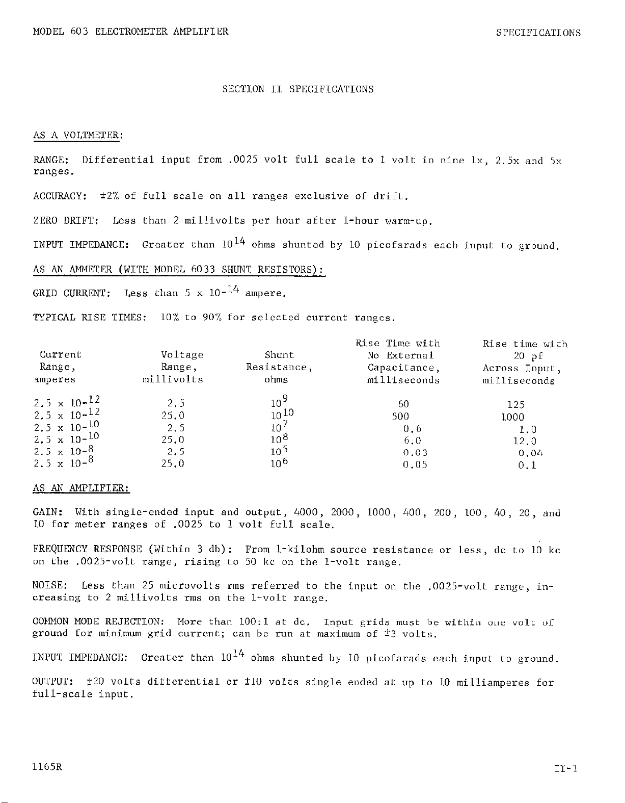
SECTION II SPECIFICATIONS
AS A VOLTMETER:
SPECIFICATIONS
RANGE:
Differential input from .0025 volt full scale to 1 volt in nine lx, 2.5x and 5x
ranges.
ACCURACY:
ZERO DRIFT:
INPUT IMPEDANCE:
*2% of full scale on all ranges exclusive of drift.
Less than 2 millivolts per hour after l-hour warm-up.
Greater than 1014 ohms shunted by 10 picofarads each input to ground.
AS Aiv METER (WITH MODEL 6033 SHUNT RESISTORS):
GRID CURRENT:
TYPICAL RISE TIMES:
2.5 x LO-12
2.5 x LO-l2
2.5 x LO-10
2.5 x LO-10
2.5 x 10-g
2.5 x 10-s
Less than 5 x lo-l4 ampere.
10% to 90% for selected current ranges.
Voltage
Range >
millivolts
2.5
25.0
2.5
25.0
2.5
25.0
Shunt
Resistance,
ohms
109
10 10
107
108
105
10’5
Rise Time with
No External
Capacitance,
milliseconds
60
500
0.6
6.0
0.03
0.05
Rise time with
20 pf
Across Input,
milliseconds
125
1000
1.0
12.0
0.04
0.1
AS AN AMPLIFIER:
GAIN:
With single-ended input and output, 4000, 2000, 1000, 400, 200, 100, 40, 20, and
10 for meter ranges of .0025 to 1 volt full scale.
FREQUENCY RESPONSE (Within 3 db):
on the .0025-volt range,
rising to 50 kc on the l-volt range.
From 1-kilohm SOUL-ce resistance ox less, dc to 10 kc
NOISE: Less than 25 microvolts rms referred to the input on the .0025-volt range, in-
creasing to 2 millivolts rms on the l-volt range.
COMMON MODE REJECTION: More than 1OO:l at dc.
Input grids must be within one volt of
ground for minimum grid current; can be run at maximum of i3 volts.
INPUT IMPEDANCE: Greater than 1014
OUTPUT:
f20 volts differential or i-10 volts single ended at up to 10 milliamperes for
ohms shunted by 10 picofarads each input to ground.
full-scale input.
1165R
11-l
Page 6
MODEL 603 ELECTROMETER AMPLIFIER SPECIFICATIONS
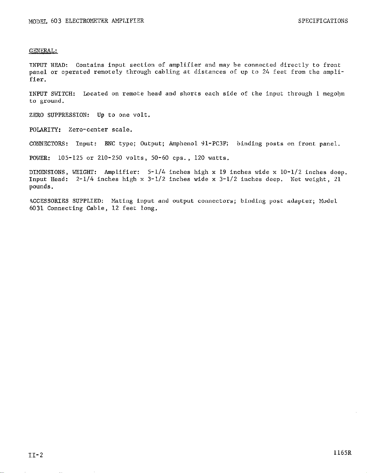
GENERAL:
INPUT HEAD: Contains input section of amplifier and may be connected directly to front
panel or operated remotely through cabling at distances of up
to
24 feet from the ampli-
fier.
INPUT SWITCH:
Located on remote head and shorts each side of the input through 1 megohm
to ground.
ZERO SUPPRESSION:
POLARITY:
CONNECTORS:
POWER:
Zero-center scale.
Input: BNC type; Output; Amphenol 31-PC3F; binding posts on front panel.
105-125 or 210-250 volts, 50-60 cps., 120 watts.
DIMENSIONS, WEIGHT:
Input Head:
2-l/4 inches high x 3-l/2 inches wide x 3-l/2 inches deep.
up to one volt.
Amplifier: 5-l/4 inches high x 19 inches wide x 10-l/2 inches deep.
pounds.
4CCESSORIES SUPPLIED:
Mating input and output connectors; binding post adapter; Model
6031 Connecting Cable, 12 feet long.
Net weight, 21
II-2
1165R
Page 7
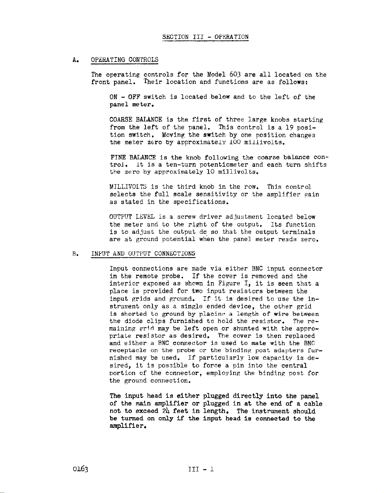
OPZRATING CONTROLS
A.
The operating controls for the Model 603 are all located on the
front panel.
- OFF switch is located below and to the left of the
ON
panel meter.
COARSE BALANCE is the first of three large knobs starting
from the left of the panel. This control is a 19 posi-
tion switch.
the meter zero by approximatelv 100 millivolts.
FINE BALANCE is the knob following the coarse balance control.
the zero by approximately 10 millivolts.
MILLIVOLTS is the third knob in the row. This control
selects the full scale sensitivity or the amplifier Cain
as stated in the specifications.
OUTPUT LEVEL is a screw driver adjustment located below
the meter and to the right of the output. Its function
is to adjust the output dc, so that the output terminals
are at ground potential when the panel meter reads zero.
SECTION III - OPERATION
Their location and functions are as follows:
Moving the switch by one position changes
It is a ten-turn potentiometer and each turn shifts
B.
INPUT AND OU'PPUT CONNECTIONS
Input connections are made via either BNC input connector
in the remote probe.
If the cover is removed and the
interior exposed as shown in Figure I, it is seen that a
place is provided for two input resistors between the
input grids and
ground.
If it is desired to use the instrument only as a single ended device, the other grid
is shorted to ground by placing a length of wire between
the diode clips furnished to hold the resistor.
maining pr'd may be left open or shunted with the appropriate resiStor as desired. The cover is then replaced
and either a BNC connector is used to mate with the BNC
receptacle on the probe or the binding post adapters fur-
nished may be used.
If particularly low capacity is de-
sired, it is possible to force a pin into the central
oortion of the connector, employing the binding post for
the ground connection.
The input head is either plugged directly into the panel
of the main amplifier or plugged in at the end of a cable
not to exceed 2b feet in length. The instrument should
be turned on only if the input head is connected to the
amplifier.
The re-
0163 III - 1
Page 8
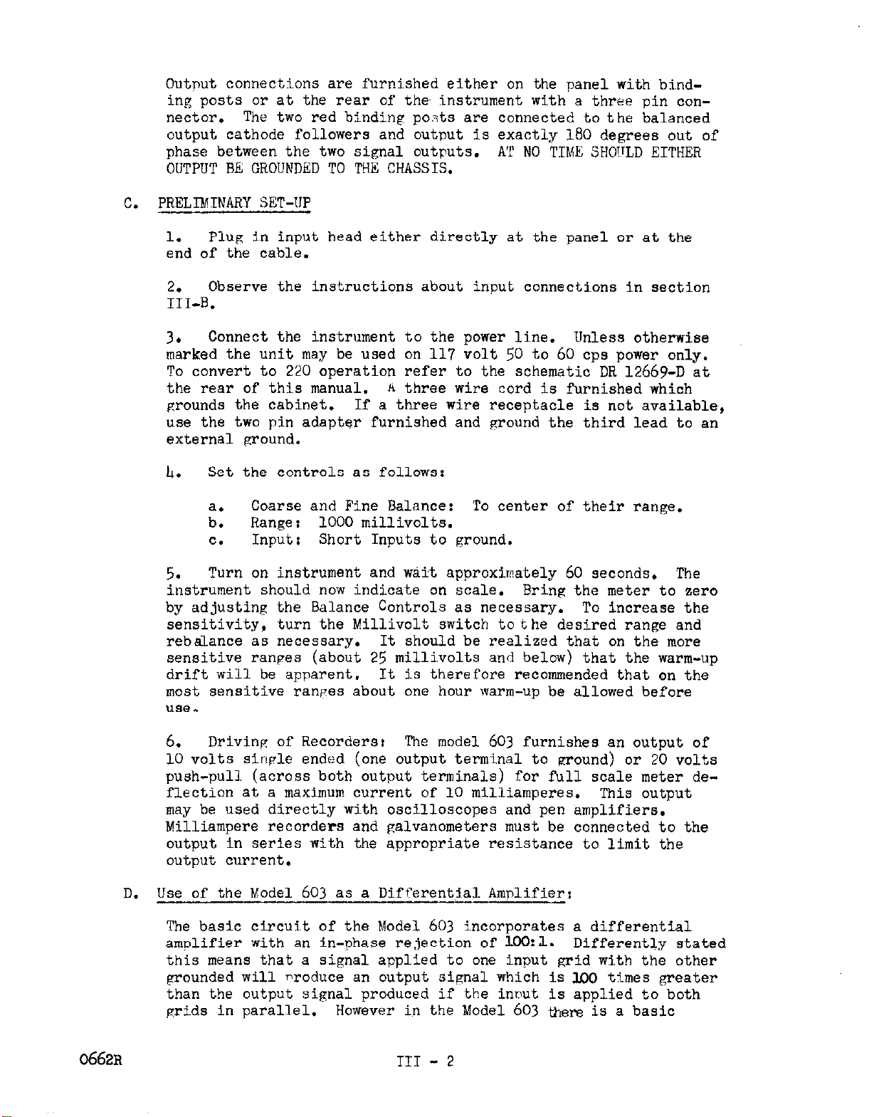
Outnut connec~tions are furnished either on the panel with bind-
ing posts or at the rear of the instrument with a three pin connector. The two red binding po.+,s are connected to the balanced
output cathode followers and output is exactly 180 degrees out of
phase between the two signal outputs.
AT NO TIME SHOTTLD EITHER
OUTPUT BE GROUNDED TO THE CHASSIS.
PRELIMINARY SET-UP
C.
1.
Plug in input head either directly at the panel or at the
end of the cab1.e.
Observe the instructions about input connections in section
2.
III-B.
3.
Connect the instrument to the power line. Unless otherwise
marked the unit may be used on 117 volt 50 to 60 cps power only.
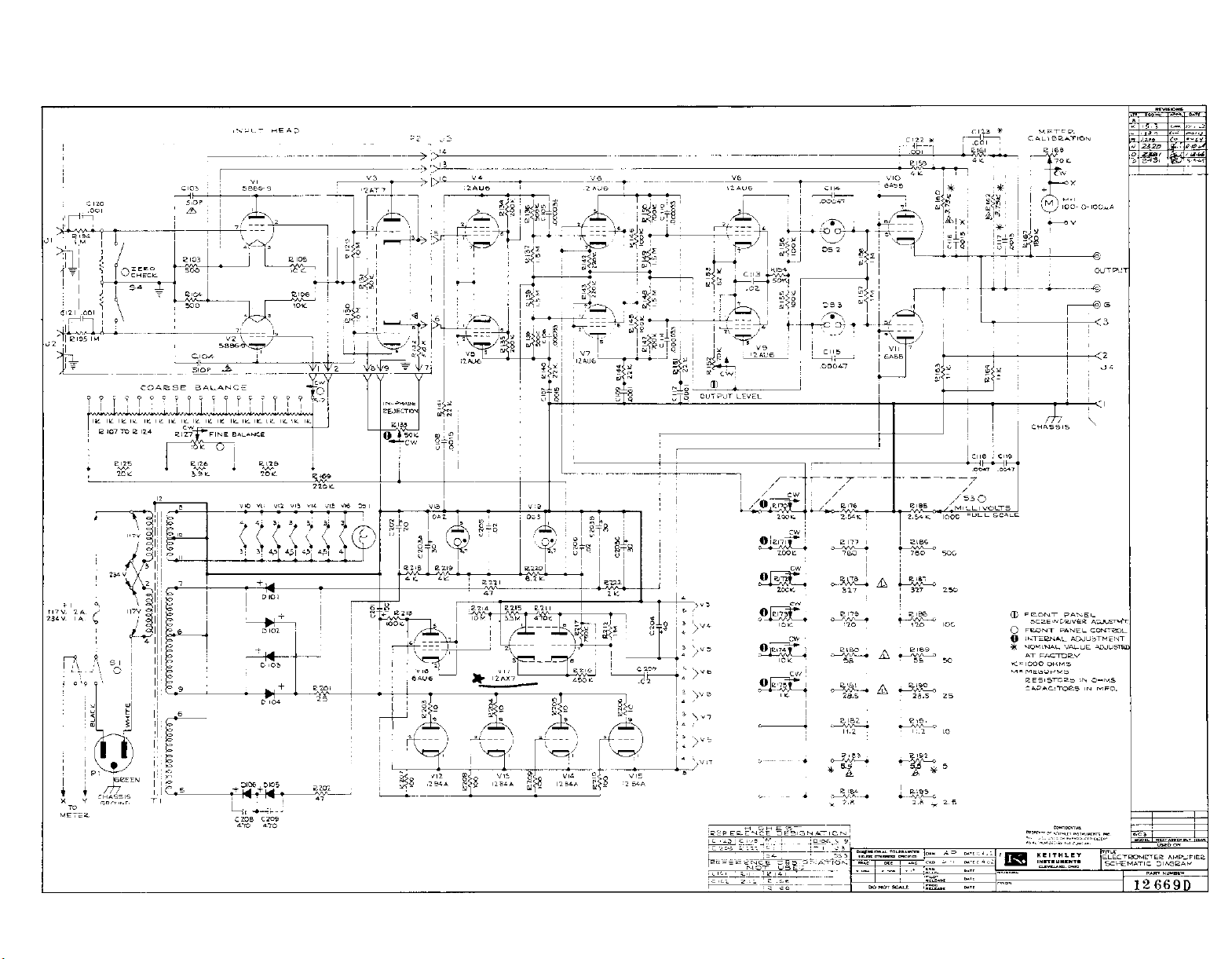
To convert to 2’20 operation refer to the schematic DR 12669-D at
the rear of this manual.
grounds the cabinet.
A three wire cord is furnished which
If a three wire receptacle is not available,
use the two pin adapter furnished and ground the third lead to an
external ground.
IL.
Set the controls as follows:
Coarse and Fine Balance: To center of their range.
Range: 1000 millivolts.
Input: Short Inputs to ground.
on instrument and wait approximately 60 seconds.
5.
a.
b.
C.
Turn
instrument should now indicate on scale.
The
Bring the meter to zero
by adjusting the Balance Controls as necessary. To increase the
sensitivity, turn the Millivolt switch to the desired range and
rebalance as necessary. It should be realized that on the more
sensitive ranpes (about 25
millivolts
and
below)
that the warm-up
drift will be apparent. It is therefore recommended that on the
most sensitive ranges about one hour warm-up be allowed before
use.
0662~
6.
Driving of Recorders: The model 603 furnishes an output of
10 volts sinple ended (one output terminal to around) or 20 volts
push-pull (across both output terminals) for full scale meter deflection at a maximum current of 10 milliamperes. This output
may be used directly with oscilloscopes and pen amplifiers.
Milliampere recorders and galvanometers must be connected to the
output in series with the appropriate resistance to limit the
output current.
Use of the Model 603 as a Differential Amnlifier:
D.
The basic circuit of the Model 603 incorporates a differential
amulifier with an in-phase rejection of 1Wk. Differently stated
this means that a signal applied to one input grid with the other
grounded will produce an output signal which is 100 times greater
than the output signal produced if the innut is applied to both
grids in parallel.
However in the Model 603 t&E is a basic
TIT - 2
Page 9
restriction that the DC potential between the grids and ground
must not exceed one volt plus or minus with respect to around
if the grid current specifications are to be met.
Nevertheless, where the balanced input can be used, it will give
considerable improvement in spurious signal rejection if it can
be arranged that the desired signal appears across the input
grids while any spurious signal is picked up equally and in
phase at the two grids.
In this way the snuri~ous signal will
be discrimi.nated against and the desired sivnal will be ampli-
fled.
If the balanced input is used,
it should be remembered that each
input grid must have a DC return to ground and it is not sufficient to connect between the two input terminals. Very often the
resistance of the surroundings will provide the return path to
ground.
However if a sufficient return path does not exist it
can be provided by shunting resistors to ground in the place provided in the input head. (See section IIIB.)
If this precaution
is not observed the input will rapidly charge up due to grid current flow and the amplifier will be inoperative until a return
path is provided. The value of resistance to ground will best
be determined by considering the impedance that, in the first
place, is necessary and the permissible voltage that can be al-
lowed to build up at the grids due to grid current.
GENERAL PRECAUTIONS:
E.
1.
Input wires should be as short as possible and well shielded
in order to reduce power line pickup as well
as
the pick-up of
stray electrostatic fields. When the Model 603 is used at its
maximum input impedance, electrostatic pick-up must be carefully
eliminated. In some cases it may be necessary to shield the
entire test object.
If the high input resistance of the Model 603 is to be
2.
realized in practice,
careful attention should be paid tothe
quality of insulation used in the input circuit, Ordinary rubber
and plastic insulation should be avoided in favor of teflon or
polystyrene. Insulation for switches,
standoffs and bushings in
contact with the signal lead should be made of polystyrene, polyethylene, ceramic, teflon or other high quality insulation ma-
terial. If cables are necessary, most types of polyethylene or
teflon insulated cable will be satisfactory. However if critical
work at low levels is contemplated, a very substantial reduction
in cable noise will be obtained with a coaxial cable using a
graphite-coated dielectric. One satisfactory type is Amphenol
21-537.
Avoid leaving the input grids floating and unshielded.
3.
Large signals can be induced at the input of the amplifier.
Although no permanent damage will occur, some temporary loss
of DC stability may be experienced.
III - 3
Page 10

4. If the power line is especially unstable 8om.e improvement
in stability can be obtained with a line regulating transformer.
Some attention should be given to providing adequate venti-
5.
lation for the amplifier since the power dissipation is about
120 watts.
precautions are necessary.
If it is used with end-frames in the open air no
However, if the instrument is used
with rack mounting, it will pay dividends in longer instrument
life if forced air ventilation is provided. Several blowers
for rack mounting are available such as Bud Radio Type B25.
FIG. 1
Page 11

SECTION IV --
CIRCIJIT DESCRIPTION
The Model 603 is a direct-coupled DC amplifier with a balanced
electrometer input followed by three stages of balanced pentode
amplification and two output cathode-followers which drive the
output stage and the balanced feedback loops.
The amplifier derives a high degree of DC stability by the use
of balanced circuitry and close regulation of all critical plate
and filament supplies.
A.
Detailed description of the Amplifier (refer to DR 12669-D the
circuit schematic):
The input
head.
tubes,
Vl and
Vl, V2 and V3 are contained in the remote input
V2
are type 5886 electrometer tubes and V3 is a
cathode follower used to transmit the signal at a relatively low
impedance to the main amplifier. The filaments of Vl and V2 are
supplied from the regulated R'+ supply via R105 and R106. The fila-
ment current then flows through RlO3 and RlOk. The drop across
these resistors furnishes the
bias
for
the electrometer
tubes.
A bias voltage of five volts is used to allow some measure of
input voltage variation around ground when operating the amplifier with a balanced input.
Resistors R103 and RlOh also serve
as the return point for the negative feedback voltage from the
cathodes of VlO and Vll, the output cathode-followers.
This feedback voltage is attenuated by R159, R160, R161, R162 and resistors
R176 through Rl93.
Resistors R176 to R193 are chosen to set the
gain of the amplifier.
Due to the fact that the input tubes are filamentary types, it is
not convenient to float the filaments above ground.
Therefore in
order that some measure of in-phase rejection is obtained, local
feedback from the cathodes of V& and V5 to the screens of Vl and
V2 is used to provide rejection against common mode signals.
The principle of operation is as follows:
If a signal.of the same
magnitude and phase is received at each input grid simultan&ouslyi
equal signals are transmitted to each grid of Vh and V5 via cathode
followers V3a and V3b.
Since Vii and V5 form a differential amplifier, an equal in-phase signal received at each input grid will
cause the cathode of the stage to move nearly as far as the grids.
This cathode signal is fed back to the screens of Vl and V2 via
R107 through R128. It will be found that the direction of the
feedback signal is such as to cancel the input signal. On the
other hand if the signal to the two input grids is equal but the
signal each input grid receives is 180° out of phase with respect
to the other, then when the signal arrives at the grids of Vh and
V5, the plate current in one tube will increase and the plate current in the other tube will decrease in such a manner as to cause
no change in potential at the cathodes of these tubes.
In this
way no signal is fed back and the full forward gain of the first
two stages is utilized.
IV - 1
Page 12

Resistor8 R107 through ~128 vary the DC potential on the electrometer tube screen8 for the purpose of balancing the output voltage
of the amplifier.
These controls have small effect on the local
feedback circuit described in the above paragraph. Rl33 is adjusted for the maximum in-phase rejection and does not need further
attention unless the tubes are changed.
From VIJ and V5, the signal is transmitted via ~136, R137, ~138 and
R139 to ~6 and V7.
turned to B- via R&2 and Rlb3.
The cathodes of V6 and V7 are *eparatelY re-
The par-pose of this connection
is to provide a means of varying the loop gain of the amplifier
as the feedback is varied to change the overall sensitivity. This
is n8ces3ary to prevent oscillation. To this end it can be appre-
ciated that if now Resistors R170 to R175 are shunted across the
cathodes of ~6 and V7 the gain of the stage can be varied according to the size of the resistor from about 1 to approximately 200.
The loop gain is thus varied as the sensitivity is changed by S-3
so that the feedback factor will not be too large for the amplifier
to be stabilized against oscillation by stabilizing networks pro-
vided by C103, ClOL, R&O and C107, Rlbl and C108, R&L and Clog,
Rlsl, and Cll.2. 'The resistors Rl70 through R175 which adjust the
loop gain arc adjustable so that in the initial line-up of the
amplifier they may be adjusted for the maximum bandwidth possible
on each range with an absence of ringingand peaking.
In general
this adjustment will remain fixed for an indefinite period after
once adjusted. However as the instrument ages or if a tube is replaced in the amplifier readjustment of these controls as outlined
in the maintenance section may‘be desirable.
The remainder of the amplifier is relatively conventional. Resistance coupling is again used between V6, V7 and V8. V9.
Between ~8,
V9 and VlO, Vll. however, coupling is through IX32 and IE33, neon
lamp*.
These were used to prevent attenuation of the
signal into the output tubes so that a larger dynamic range could
be obtained from the output stage than otherwise possible. The
output cathode followers are "oentode" connec~ted.
That is, the
screen8 are supplied from the well regulated B+ supply while the
plates derive their supply from the unregulated supply. The advan-
tage of ~this connection is that line transient8 and ripple present
in the unregulated plate supply will hardly affect the tube output,
although very little power is required from the well regulated
supply to which the 3cresn is returned.
B. Power Suoply Voltages:
The following unregulated potentials are obtained from the
transformer secondaries by means of silicon rectifiers and elec-
trolytic filter sections:
(1) Plus 210 volts fromD102 and D104 to the input of the electronic
regulator (The plates of V12 to Vl5) and the plates of VlO and VU.
The current drain is approximately 210 milliamperes.
IV - 2
Page 13

(2) Minus 210 volts from DlOl and DlO3 to the cathode load resistors
of no ana vu, ~163 and ~164.
(3)
Minus
to the negative voltage regulator tube ~18. 'The current drain is
about 25 millismperes.
ulator
The foLiowing regulated voltages are obtained for operation of the
amplifier:
(I.) Plus 100 volts from the electronic regulator consisting of
VI.2 through Vl7. This potential supplies the B+ voltage for all
amplifier tubes with the exception of the output stage; the fila-
ments for the electrometer tubes by means of dropping resistors
R105 and ~106; and the filament voltages for tubes V3, V4, V5, ~6,
V7, V8, Vg, and V17 which are in series across the plus 100 volt
suppLv*
(2)
Minus
of ~18, a type OA2 voltage regulator tube. This tube supplies bias
voltage for several amplifier stages and pre-regulates the supply
to
ny.
(3)
Minus 85 volts. This is the reference potential for the electronic regulator and the negative supply for the first three amp.
lifier stages.
370
volts
v1y
.
The drain is about 180 ma.
150
volts: This potential is obtained from the cathode
from ~DlO.05 and DlO6
This tube then supplies a second voltage reg-
The current drain is 40 millismperes.
through RZOZ,
R218
and R219
C. Electronic Regulator:
The electronic regulator consists of a comparator tube, V17, an smplifier
tube, ~16, and a series regulator, VI2 through V15.
Resistors R2l2 and RZ17 are so chosen that, with a regulated output of 100
volts, the junction will be at ground potential.
connected to this junction and the other is grounded, any difference or error
signal is amplified by Vl7.
~16,
The filament of the comparator tube, Vl7, is connected in the series string
will cause the output to chenge by 0.02%.
the output of which controls the grids of the series regulators, VI.2
through Vl5, in such a way as to minimize the change in the output voltage.
across the regulated output for greater stability. A lO$ line voltage change
The output of V17 is further amplified by
Since one grid of Vl'( is
1162~
JJJ-3
Page 14

SECTION V -- MAINTENANCE AND TROUBLE SHOOTING
Maintenance:
A.
No periodic maintenance is required. Tubes Vl, V2, Vh and Vs are
selected and should only be replaced by the proper Keithley replacement part. When replacing a tube realign frequency response as outlined in Section V-B 2 b for all ranges.
B.
Trouble Shooting5
A thorough understanding of Section IV, Circuit.Description
1.
will be of considerable aid in tracing any circuit troubles.
Specific Faults: Listed below are several of the cotion ser-
2.
vice difficulties that may~be encountered with this instrument.
If the fault is not covered in the listing below, refer to secticn
3
below where a general check-out procedure is outlined.
a.
the most common symptom of malfunction. Unfortunately, since
this instrument is a direct-coupled amplifier, it will seldom
be possible to localize the fault simply, since the failure
to balance can be caused by either faults in the power supplies, or in any stage of the amplifier. First check all
power supply voltages as given in section IV B, if not correct refer to section V-B3b for detailed instruction.
voltages are correct, refer to section V-B3a which gives a
detailed plan of action for trouble shooting the amplifier.
b.
sensitive ranges: This can be caused by either a defective
amplifier tube (usually VI., V2, V3, Vh, or Vg) or a defect in
the power supplies. To trace the cause, first place the instrument on a variable source of line power such as a Variac
or powerstat transformer.
ly from 105 to 130 volts. If there is only a meter division
or two change in indication with this variation of line voltage, the power supnlies are working properly and the erraticness is in the amplifier. If it is determined that the power
supply is at fault consult section V-B3b for instructions on
the power supply. On the other hand if the power supply is
operating correctly, change first the input tubes Vl and V2
and if this does not cure the trouble, proceed in order to
change the tubes in the later stages.
input head may be plugged into the amplifier to check the
performance.
Instrument will not balance: In general, this will be
Noise or erratic output or meter indications on the more
Vary the line voltage fairly rapid-
If available, a spare
If the
0662
There is also a chance that noise or erratic output can be
caused by a defective resistor or a defective solder joint.
If it is not possible to cure the trouble by changing tubes
or trouble-shooting the power supply, the procedure in section
V-B3a for a systematic inspection of the amplifier should be
followed.
V-l
Page 15

Excessive Drift: The trouble shooting procedure is ex-
C.
actly the same as indicated in 2b above for the localization
of noise. In brief drift can be caused by defective Input
tubes, a power supply not regulating properly or a defective
component.
Oscillation on any range or poor high-frequency response:
d.
As pointed out in Section IV,
Circuit Description, potentio-
---
meters R170 through R175 are used to set UP the freauencv
response from range to range. If one of these are improperly
set or if tubes have been changed in the amplifier it is
possible that one of these potentiometers may have to be ad-
justed.
To adjust the response or stop oscillation, locate
the potentiometer involved as shown on the schematic. (These
potentiometers are located, accessible by removing the bottom
plate, on the front transverse channel of the chassis.) Then
with an external oscillator with a range of approximately
20 cps to 1 mc., apnly a signal to one input, with the other
grounded, of'less than the full scale signal for that range.
On the more sensitive ranges a divider following the oscillator
will usually be necessary. Sweep the oscillator through a fre-
quency range of about lkc to 500kc. The frequency response
should be adjusted so that the instrument does not peak more
than 3 db through the range.
It is not possible to adjust the
three lowest ranges but this usually will not be necessary.
With the remote head plugged into the panel, the upper three
db point should be adjusted to only 50 kc even if it is pos-
sible to achieve a hl,ghrr'fre,quency response on some ranges
if it is contemplated that the head will then be used on the
and of a cable, since the cable will cause instability if the
adjustment is made for a wider bandwidth. With a 50 kc adjustment, the frequency response will be satisfactory with the
cable attached. Finally if the constancy of freouency response
near the high-frequency roll-off is of importance, it is of
advantage to check the frequency response of the amplifier
with the length of cable being used and adjust it to suit.
0163
If oscillation cannot be stopped by the above means, check the
following components which are employed in stabilizing loopsr
C103, ClOh, RlbO, RlLl, C107, C108, RlU, RlSl, C109, C112,
C118. c119.
Replace any defective component.
If the frequency response is less than specifications this is
usually due to tubes with low transconductance and the remedy
is to replace tubes until the frequency response is normal.
If no success is experienced in stoppine oscillation with the
procedures outlined above,
put.
In rare cases it may happen that the power supply will
check the power supply B-plus out-
oscillate. For a cure see Section V-B3b.
v-2
Page 16

General Procedures for Trouble-Shooting.
3.
a.
After this is done, the feedback loops are broken and it is
back voltages introduced by the feedback connections.
The Amplifier:
If the amplifier cannot be zeroed with the front panel controls, the first step is to disable the negative feedback
loops.
tubes from their socket and shorting both outputs to ground.
possible to study the operation of each stage without the pos-
sibility of the operating poi.nt being disturbed bir large feed-
Now short both input grids to Fround and proceed to measure
the plate pot.entials of the first stage. These plate poten-
tials should be adjustable by means of the front panel zero
controls to 15 volts.~ If manipulation of the front panel aero
controls allows the first stage tubes to pass through the correct operating voltage, it can be assumed that the stage is
operating correctly.
tials, per the voltage-resistance diagram at the rear of the
manual.
be at approximately 5.5 volts.
100 volts, the electrometer tube filament has opened and Vl
and V2 should be replaced with a new matched pair of electrometer tubes (Keithley part number EV
This may be done in most cases by removing the output
If not, check the other electrode poten-
Lead 3 of the electrometer tubes, (F - plus) should
If it is found to be at plus
5886-9).
If, however, the correct potentials are obtained at the plates
of Vl and V2, proceed to pins 6 and 7 of V3 and repeat the
procedure.
indicated on the voltage-resistance diagram. As before, if it
does not,
the various resistances to ground. If the trouble is not at
V3, proceed in a similar manner step by step throwh the amplifier until finally the fault is found. Note that the filaments
of V3 through V9 and V17 are in series. If these tubes do not
light one has a burnt out filament and both the amplifier and
power suppl:? will be disabled.
b.
The negative voltage regulator consists of ~18 and V19 which
are gas-filled diodes operating from the unregulated minus
325 volt supply.
potentials are incorrect check to see if ~18 or V19 are lit.
ed out that it is rare for a voltage-regulator tube to fail
Power Supply:
If they are not measure the voltage between R202 and R215. If
it is not approximately 380 volts, either the rectifier or
filter capacitor has failed or else there is a short to ground.
Check and replace components if necessary.
and replacement should be avoided in uncertain situations.
The voltage again should swing through the value
check other voltages at that stage and,if necessary
If either the minus 150 or minus 85 volt
It should be point-
1162~
v-3
Page 17

There is also available a minus 200 volt potential which is
not regulated an is used for the negative return of the
output cathode-followers. This potential may be measured
at the junction of R222 and C203c. If this potential is
not correct check the corresponding rectifiers and filter
capacitors.
The positive power supplies consist of an.unregulated
200 volt supply and a regulated 100 volt supply. The
200 volt supply is used to supply the plates of the output cathode followers. Any defect in the 200 volt supply
can be easily fourrd since the supply is a conventional
rectifier-filter system. The regulated 100 volt supply is
somewhat more involved.
If the trouble has been traced to the 100 volt regulated
supply and it has been determined that the unregulated
200 volt supply is correct, check to see that V17, the
12AX7 has filament voltage. As' seen from the schematic
it is in series with several of the amplifier tubes and
a break in any one of these filaments will disable the power
supply as well as the amplifier. If it is correct, check
the voltage at the junction of
minus 85 volts. If it is incorrect the trouble is in the
negative supply. If the trouble still persists, check to
see If V1~2 through V17 are defective and replace if neces-
sary. Check the output with an oscilloscope for oscillation.
If oscillation is found probably C2Ot( is defective. If the
trouble still remains check each resistor for a changed
value.
~216
and R217. It should be
0163
v - 11
Page 18

MODEL 603 ELECTROMETER AMPLIFIER REPLACFABLE PARTS
SECTION 6.
6-l. REPLACEABLE PARTS LIST.
ponents of the Model 603 and its accessories.
designation,
the part description, a suggested manufacturer, manufacturer's
REPLACEABLE PARTS
The Replaceable Parts List describes the com-
The List gives the circuit
part number and the Keithley Part Number. The name and address of the manu-
facturers listed in the "Mfg.
Code" column are contained in Table 2.
6-2. HOW TO ORDER PARTS.
a. For parts orders,
the Keithley Part Number,
include the instrument's model and serial number,
the circuit designation and a description of the part.
All structural parts and those parts coded for Keithley manufacture (80164)
must be ordered from Keithley Instruments, Inc.
in the Replaceable Parts List,
completely describe the part, its function and
In ordering a part not listed
its location.
Order parts through your nearest Keithley distributor or the Sales
b.
Service Department, Keithley Instruments, Inc.
=mP
CbVar
CerD
ampere
Carbon Variable
Ceramic, Disc
Mil. No.
n
Military Type Number
ohm
Corn1 Commercial
Comp
CompV
DCb
ETB
Composition
Composition Variable
Deposited Carbon
Electrolytic, tubular
Poly Polystyrene
P
ii
pica (10-12)
micro (10e6)
v volt
f
farad Var Variable
k kilo (103) w watt
ww Wirewound
M or meg mega (106) or megohms wwvar Wirewound Variable
m
Mfg.
milli (10A3)
Manufacturer
TABLE 1.
Abbreviations and Symbols.
1164R
6-l
Page 19

REPLACEABLE PARTS
MODEL 603 ELECTROMETER AMPLIFIER
MODEL 603 REPLACEABLE PARTS LIST
(Refer to Schematic Diagram 12669D for circuit designations.)
CAPACITORS
Circuit Mfg. Mfg. Keithley
Desig.
Value
Rating
TYPO
Code Part No.
Part No.
Cl01
Cl02
Not Used
Not Used
Cl03 (i) 510 pf
Cl04 (i)
510 pf
Cl05 33 pf
Cl06
Cl07
Cl08
Cl09
Cl10
Cl11
Cl12
Cl13
Cl14
Cl15
Cl16
Cl17
Cl18
Cl19
Cl20 (i)
Cl21 (i)
Cl22
Cl23
33 pf
.0015 Kf
.0015 pf
.OOOl pf
33 pf
33 pf
.OOOl wf
.02 IJ.f
470 pf
470 pf
,'1.0015 vf
a.0015 pf
.0047 pf
.0047 Ilf
.OOl pf
.OOl pf
..OOl I*f
*.001 vf
500 "
500 "
1000 "
1000 "
1000 "
1000 "
1000 "
1000 "
1000 "
1000 "
1000 "
1000 "
1000 "
1000 "
Poly
Poly
CerD
CerD
CerD
CerD
CerD
CerD
CerD
CerD
CerD
CerD
CerD
CerD
71590 CPR-510.l
71590 CPR-5103 Cl38-51OP
72982
72982
72982
72982
72982
72982
72982 831U2M330K C22-33P
72982
72982
72982 831Z5V471P C22-470P
72982
72982
1000 " CerD 72982
1000 "
CerD
72982
1000 " CerD 72982
500 "
500 "
1000 "
Poly
Poly
CerD
1000 " CerD
71590
71590
72982
72982
C138-51OP
831U2M330K
831U2M330K
C22-33P
C22-33P
8OlZ5V152P C22-.0015M
801Z5V152P C22-.0015M
831X5RlOlK c22-1OOP
831U2M330K C22-33P
831X5RlOlK c22-1OOP
841Z5V203P C22-.02M
831Z5V471P C22-470P
8OlZ5Vl52P C22-.0015M
801Z5Vl52P C22-.0015M
BllZ5V472P C22-.0047M
811Z5V472P C22-.0047M
CPR-1OOOJ C138-.OOlM
CPR-1OOO.J C138-.OOlM
80125V102P C22-.OOlM
8OlZ5V102P C22-.OOlM
c201
c202
C203
c204
C205
C206
C207
C208
c209
150 I*f
20 pf
3x30 IJ.f
40 Ilf
.02 IJ.f
.02 pf
.02 iJ.f
470 pf
470 pf
300 "
600 v
350 "
250 "
1000 "
1000 " CerD 72982
1000 "
1000 " CerD
1000 "
Circuit
Desig.
Type
DlOl Silicon
D102 Silicon
YcNominal value, factory set.
(i) Located in Input Head.
6-2
ETB
ETB
ETB
ETB
CerD
CerD
CerD
00656
14655
12674
56289
FP131 C46-150M
BR20-600 C35-20M
ME50039 C52-3x30M
TVA1511 C27-40M
72982 841Z5V203P
841Z5V203P C22-.02M
72982
71590
71590
841Z5V203P
DD471 C64-470P
DD471
DIODES
Mfg.
Number Code
lN3255 02735
lN3255
02735
C22-.02M
C22-.02M
C64-470P
Keithley
Part No.
RF-17
RF-17
1165R
Page 20

MODEL 603 ELECTROMETtiR AMPLIFIER
DIODES (Cont'd)
REPLACEABLE PARTS
Circuit
Desig.
D103
D104
D105
D106
Circuit
Des&. Description
DSl
---
DS2 Neon Lamp (Mfg. No. NE-81)
DS3 Neon Lamp (Mfg. No. NE-al)
Fl(117v) Fuse, 2 amp, 3 AG (Mfg. No. 312002)
Fl(234v)
_-Jl (i) Receptacle, bnc, Input, Mil No. UG-1094/U (Mfg.
Lamp (Mfg. No. 51)
Pilot Light Assembly (Mfg. No. 755-621)
Fuse,
Fuse Holder (Mfg. No. 342012)
No. 31-221)
TYPO
Silicon lN3255
Silicon lN3255
Silicon
Silicon lN3255
MISCELLANEOUS PARTS
1 amp, 3 AG (Mfg. No. 312001)
Number
lN3255
Mfg.
Code
02735
02735
02735
02735
Keithley
Part No.
RF-17
RF-17
RF-17
RF-17
Mfg.
Code
08804
72619
08804 PL-6
08804
75915 FU-13
75915
75915
02660
Keithley
Part No.
PL-8
PL-9
PL-6
FU-7
FH-3
cs-15
J2 (i) Receptacle, bnc, Input, Mil. No. UG-1094/U (Mfg.
___
---(i)
___
53
___
54 Receptacle, Microphone, Output (Mfg. No. 91-PC3F)
_--
--__-
Ml Meter 80164
Pl
___
P2 (i)
Sl
s2 Rotary Switch less components, BALANCE COARSE 80164
---
No. 31-221)
Plug, bnc, Mate of Jl and 52, Mil. No. UG-88/U
(Mfg. No. 31-002)
Binding Post (Mfg. No. 938-A)
Binding Post Adapter furnished for Jl and 52, Mil
No. UG-1090/U (Mfg. No. 1090)
Socket (Mfg. No. 126-150)
See P2 for mate of 53
Plug, Microphone, Mate of J4 (Mfg. No. 91-MC3M) 02660
Binding Posts, OUTPUT (Mfg. No. DF31BC)
Binding Post, G (Mfg. No. DF31BC)
Power Cord Set, 6 feet (Mfg. No. 4638-13) 82879
Cable Clamp (Mfg. No. SR-6P-1)
Plug, Mate of 53 (Mfg. No. 126-151) 02660
Toggle Switch, DPDT, ON (Mfg. No. 20905-FR) 04009
Knob Assembly, Balance Coarse Switch 80164
02660
02660
24655
91737
02660
02660
58474 BP-8
58474 BP-8
28520
cs-15
cs-44
BP-1
BP-12
cs-53
CS-58
cs-59
ME-18
co-2
cc-7
CS-52
SW-14
SW-65
15459A
(i) Located in Input Head.
116SR
6-3
Page 21

REPLACEABLE PARTS
MODEL 603 ELECTROMETER AMPLIFIER
MISCELLANEOUS PARTS (Cont'd)
Circuit
Desig.
___
s3
___
54 (i)
Knob Assembly, Balance Fine Potentiometer
Rotary Switch less components, MILLIVOLTS
Knob Assembly,
Push Button, Zero Check
Tl Transformer
Circuit
Desig. Value
RlOl
R102
R103 (i)
R104 (i)
R105 (i)
R106 (i)
Not Used
Not Used
500 R
500 n
10 kn
10 kn
R107 to
R124
R125
1 kn
20 kg
Description
Millivolts Switch 80164
RESISTORS
Mfg. Keithley
Part No. Part No.
CFE-15 R12-1K
Rating
l/4%, 1 w
l/4%, 1 w
r
l/,, 5 w
l%, 5 w
l%, l/2 w
l%, l/2 w
Mfg.
TYPO
ww
ww
ww
Code
91637 RS-1A R46-500
91637 RS-1A R46-500
44655 4654 R4A-1OK
ww 44655 4654 R4A-1OK
DCb
DCb
79727
79727 CFE-15 R12-20K
Mfg. Keithley
Code
Part No.
80164 15459A
80164 SW-66
15459A
80164 13783A
80164 TR-31
R126
R127
R128
R129 (i)
R130 (F)
R131 (i)
R132 (i)
R133
R134
R135
R136
R137
R138
R139
R140
R141
R142
R143
R144
R145
3.9 kn
10 kn
20 kn,
10 wl
10 I%
50 kn
50 kn
50 kn
200 kn
200 kn
500 kn
1.5 Mo
1.5 rvn
500 kn
22 kn
22 kn
220 kn
220 kn
22 lcrl
100 kn
l%, l/2 w
3%, 5 w
l%, l/2 w
l%, 1 w
l%, 1 w
l%, l/2 w
l%, l/2 w
lO%, 2 w
l%,
l%,
l%,
l%,
l%,
l%,
lO%,
lO%,
l%,
l%,
lO%, l/2 w
l%,
(i) Located in Input Head
6-4
l/2 w
l/2 w
l/2 w
l/2 w
l/2 w
l/2 w
l/2 w
l/2 w
l/2 w
l/2 w
l/2 w
DCb
WWVar
DCb
DCb
DCb
DCb
DCb 79727
79727 CFE-15 R12-3.9K
73138
A RP4-1OK
79727 CFE-15 R12-20K
91637 DC-1 R13-10M
91637
79727
DC-1
CFE-15 RLZ-50K
CFE-15 R12-50K
CompV 01121 J
DCb 79727
DCb 79727
DCb
DCb
DCb
DCb
Comp
Comp
DCb
DCb
Comp
DCb
79727 CFE-15 R12-500K
79727 CFE-15 R12-1.5M
79727
79727 CFE-15 R12-500K
01121
01121 EB Rl-22K
79727 CFE-15 Rl2-220K
79727 CFE-15 RlZ-220K
01121 EB Rl-22K
79727 CFE-15 R12-100K
CFE-15 R12-200K
CFE-15 R12-200K
CFE-15 R12-1.5M
EB
Rl3-1OM
RF'5-50K
Rl-22K
1164R
Page 22
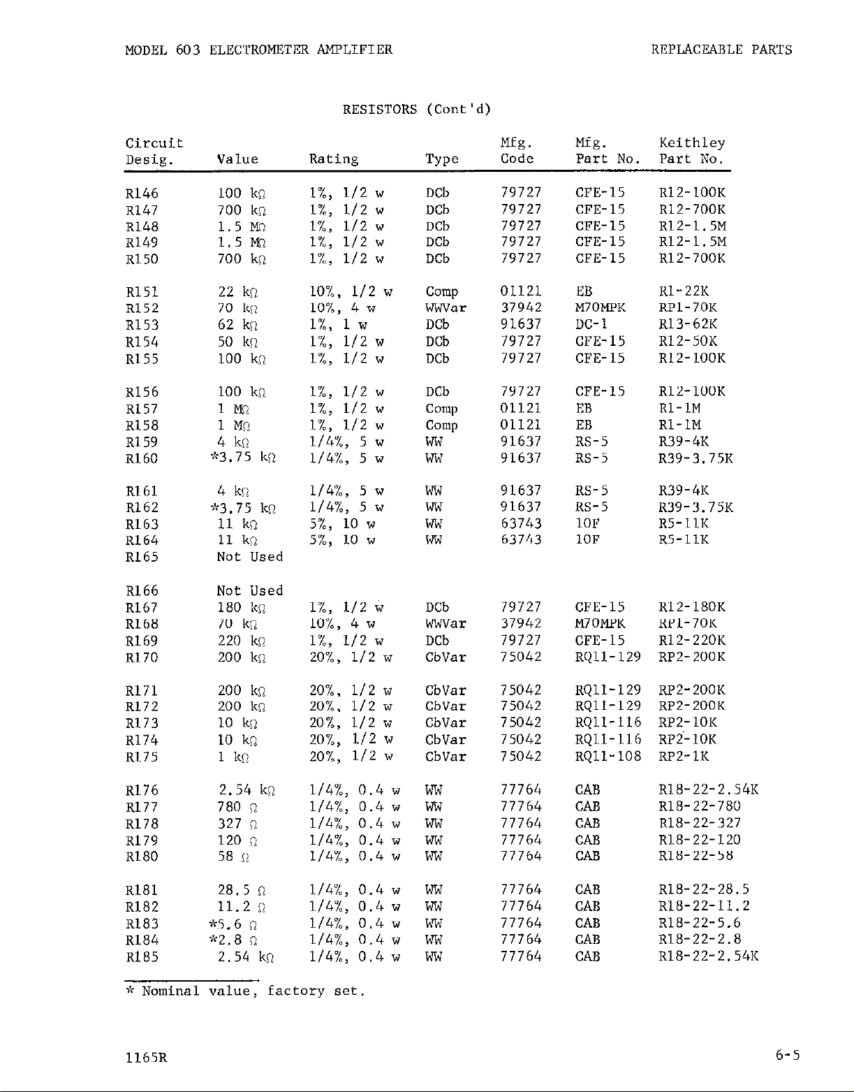
MODEL 603 ELECTROMETER AMPLIFIER REPLACEABLE PARTS
RESISTORS (Cont'd)
Circuit
Desig.
R146
R147
R148
R149
R150
R151
R152
R153
R154
R155
R156
RI57
R158
R159
Rl60
Rlbl
R162
R163
R164
R165
Value
100 ks?
700
kn
1.5 M's
1.5 ls
700
kn
22
kn
70
kn
62
kn
50
kn
100 kn
100 kn
Ii%
1MO
4 kn
9r3.75
4 kn
>b3.75
kn
ko.
11 kn
11 kn
Not Used
Rating
l%, l/2 w
l%, l/2 w
l%, l/2 w
l%, l/2 w
l%, l/2 w
lO%, l/2 w
lO%, 4 w
l%, 1 w
l%,
l/2 w
l%,
l/2 w
l%,
l/2 w
l%,
l/2 w
l%,
l/2 w
l/4%, 5 w
l/4%, 5 w
l/4%, 5 w
l/4%, 5 w
5%,
10 w
5%,
10 w
TYPO
DCb
DCb
DCb
DCb
DCb
Comp
wwvar
DCb
DCb
DCb
DCb
camp
Comp
ww
ww
ww
ww
ww
ww
Mfg.
Code
79727
79727
79727
79727
79727
01121
37942
91637
79727
79727
79727
01121
01121
91637
Mfg.
Part No.
CFE-15 RlZ-100K
CFE-15 Rl2-700K
CFE-15 R12-1.5M
CFE-15 R12-1.5M
CFE-15
EB
M70MPK RPl-70K
DC-1 Rl3-62K
CFE-15
CFE-15
CFE-15 RlZ-100K
EB
EB
RS-5 R39-4K
91637 RS-5
91637
91637
63743
63743
RS-5 R39-4K
RS-5
10F R5-1lK
10F R5-1lK
Keithley
Part No.
R12-700K
Rl-22K
Rl2-50K
RlZ-100K
Rl-1M
Rl-1M
R39-3.75K
R39-3.75K
R166
R167
R168
R169
R170
R171
R172
R173
RI74
R175
R176
R177
R17'3
R179
Rl80
R181
R182
Rl83
R184
R185
Not Used
180 kn
70
kn
220
ki2
200
kn
200
kn
200
kn
10 kn
10 kn
1 kc?
2.54 kn
780 n
327 n
120 n
58 ii
28.5 n
11.2 n
,k5.6 n
W2.8 a
2.54
kn
l%,
112 w
lO%, 4 w
l%,
l/2 w
20%, l/2 w
20%, l/2 w
20%. l/2 w
20%, l/2 w
20%,
20%,
l/4%, 0.4 w
l/4%, 0.4 w
l/4%, 0.4 w
l/4%, 0.4 w
l/4%, 0.4 w
l/4%, 0.4 w
l/4%, 0.4 w
l/4%, 0.4 w
l/4%, 0.4 w
l/4%, 0.4 w
h Nominal value, factory set.
l/2 w
l/2 w
DCb
wwvar
DCb
CbVar
CbVar
CbVar
CbVar
CbVar
CbVar
ww
ww
ww
ww
ww
ww
ww
ww
ww
ww
79727
37942
79727
75042
75042
75042
75042
75042
75042
77764
77764
77764
77764
77764
77764
77764
77764
77764
77764
CFE-15
R12-180K
M70MPK RPl-70K
CFE-15
R12-220K
RQll-129 RPZ-200K
RQll-129
RQll-129
RP2-200K
RP2-ZOOK
RQll-116 RPZ-1OK
RQll-116 RP2-1OK
RQll-108 RPZ-1K
CAB
CAB
CAB
CAB
CAB
CAB
CAB
CAB
CAB
CAB
R18-22-2.54K
R18-22-780
R18-22-327
Rl8-22-120
R18-22-58
R18-22-28.5
R18-22-11.2
R18-22-5.6
R18-22-2.8
R18-22-2.54K
1165R
6-5
Page 23

REPLACEABLE PARTS
MODEL 603 ELECTROMETER AMPLIFIER
RESISTORS (Cont'd)
Circuit
Desig. Value Rating
R186
R187
R188
R189
R190
Rl91
R192
R193
R194 (i)
R195 (i)
R201
R202
R203
R204
R205
R206
R207
R208
R209
R210
780 n
327 n
120 n
58 R
28.5 R
11.2 n
9~5.6 R
9C2.8 n
lM3
1M61
25
R
47 cl
10 n
10 n
10 n
10 n
100 n
100 n
100 n
100 R
l/4%, 0.4 w
l/4%, 0.4 w
l/4%, 0.4 w
l/4%, 0.4 w
l/4%, 0.4 w
l/4%, 0.4 w
l/4%, 0.4 w
l/4%, 0.4 w
l%,
l/2 w
l%,
l/2 w
l%, 5 w
l%, 5 w
lO%,
lO%,
lO%,
lO%,
lO%,
lO%,
lO%, l/2 w
lO%,
l/2 w
l/2 w
l/2 w
l/2 w
l/2 w
I.12 w
l/2 w
Keithley
TYPO
Mfg. Mfg.
Code Part I'lO, Part No.
ww 77764 CAB R18-22-780
ww 77764 CAB R18-22-327
ww 77764 CAB R18-22-120
ww 77764 CAB R18-22-58
ww 77764 CAB R18-22-28.5
ww 77764
CAB
R18-22-11.2
ww 77764 CAB R18-22-5.6
ww 77764 CAB R18-22-2.8
Comp 01121 EB Rl-1M
Comp 01121 EB Rl-1M
ww 91637 RS-5 R4A-25
ww 91637 RS-5 R4A-47
Comp
camp
01121
01121
EB
EB
Rl-10
Rl-10
Comp 01121 EB Rl-10
Camp 01121 EB Rl-10
01121 EB Rl-100
C&
Comp
01121
01121
01121
EB
EB
EB
Rl-100
Rl-100
Rl-100
R211
R212
R213
R214
R215
R216
R217
R218
R219
R220
R221
R222
470 kn
1Wl
100 kn
10 l%l
3.3 im
450 kn
750 ka
4kQ
4 ka
8.2 kn
47 12
2kfl
l%,
l/2 w
l%,
l/2 w
lO%, l/2 w
l%, 1 w
l%, l/2 w
l%,
l/2 w
l%,
l/2 w
3%, 7 w
3%, 7 w
lO%, 2 w
lO%, 2 w
l%, 5 w
DCb 79727 CFE-15 RlZ-470K
DCb 79727 CFE-15 R12-1M
camp 01121
DCb 91637
DCb 79727
DCb 79727
EB
DC-1 Rl3-1OM
CFE-15 RlZ-3.3M
CFE-15 Rl2-450K
DCb 79727 CFE-15
ww
91637
ww 91637
RLS-7 R7-4K
RLS-7
Rl-100K
R12-750K
R7-4K
Comp 01121 HB R3-8.2K
camp 01121 HB R3-47
ww 91637 RS-5
R4A-2K
VACUUM TUBES
Circuit
Desig.
Mfg.
NUlllbW
Keithley
Vl (i) 5886 80164 fd<EV-5886-9
V2 (i)
V3 (i) 12AT7
v4 12AU6
5886 80164
80164
94154
v5 12AU6 94154
**EV-5886-9
*"EV-12AT7
EV-12AU6
EV-12AU6
"Nominal value, factory selected.
gcwl, V2 and V3 must be matched to each other; order only as complete set.
(i) Located in Input Head.
6-6
1165R
Page 24

MODEL 603 ELECTROMETER AMPLIFIER REPLACEABLE PARTS
VACUUM TUBES (Cont'd)
Circuit
Desig.
V6
V7
V8
v9
VlO
Vll
v12
v13
v14
v15
Vl6
v17
V18
v19
Description
Mfg.
Number
12AU6 94154
12AU6 94154
12AU6 94154
12AU6 94154
6AS5 00011
6AS5 00011
12B4A 85599
12B4A 85599
12B4A 85599
12B4A 85599
6AU6 94154
12AX7 73445
OA2 86684
OG3 80164
MODEL 6032 REPLACEABLE PARTS LIST
No. Required
Per Model
Code
Mfg.
Code
Keithley
Part No.
EV-12AU6
EV-12AU6
EV-12AU6
EV-12AU6
EV-6AS5
EV-6AS5
EV-12B4A
EV-12B4A
EV-12B4A
EV-12B4A
EV-6AU6
EV-12AX7
EV-OA2
EV-OG3-240
Keithley
Part No.
End Frames
Fastener, Thumbscrew
Feet, Rubber
Attaching Parts
Machine Screw, No. 6-32UNC-2x1/2,
Rd Hd, Phillips 4
Hex Nut. No. 6-32UNC-2
Machine Screw, No. 8-32UNC-2x5116,
Rd Hd, Phillips 4
MODEL 6033 MATCHED RESISTOR PAIRS
Model No.
6033-6 106 cl
6033-7 107 n
6033-8 108 II
6033-9 109 il
6033-10 1010 n
6033-11 1011 Q
2
4 80164 FA-9
4 80164
Corn1
4 Corn1
Corn1
Resistance Value
FE-2
___
---
___
1164R
6-7
Page 25

REPLACEABLE PARTS MODEL 603 ELECTROMETER AMPLIFIER
0011 Sylvania Electric Products, Inc.
Buffalo Operations of Sylvania
Electronic Systems
Buffalo, N. Y.
0656 Aerovox Corp.
New Bedford, Mass.
1121 Allen-Bradley Corp.
Milwaukee, Wis.
2660 Amphenol-Borg Electronics Corp.
Broadview, Chicago, Illinois
2735 RCA Semiconductor and Materials
Division of Radio Corp. of America
Somerville, N. J.
Hartford, Corm.
8804 Lamp Metals and Components
Department G. E. Co.
Cleveland, Ohio
2674 Syncro Corp.
Hicksville, Ohio
4167 Efcon, Inc.
Garden City, L.I., N. Y.
4655 Cornell-Dubilier Electric Corp.
Newark, N. J.
4655 General Radio Co.
West Concord, Mass.
8520 Heyman Mfg. Co.
Kenilworth, N. J.
7942 Mallory, P. R., and Co., Inc.
Indianapolis, Ind.
4655 Ohmite Mfg. Co.
Skokie, Ill.
6289 Sprague Electric Co.
North Adams, Mass.
8474 Superior Electric Co., The
Bristol, Corm.
63743 Ward Leonard Electric Co.
Mount Vernon, N. Y.
71450 CTS Corp.
Elkhart, Ind.
71590 Centralab Division of
Globe-Union, Inc.
Milwaukee, Wis.
72619 Dialight Corp.
Brooklyn, N. Y.
72982 Gudeman Co.
Chicago, Ill.
73138 Helipot Division of
Beckman Instruments, Inc.
Fullerton, Calif. 4009 Arrow-Hart and Hegeman Electric Co.
73445 Amperex Electronic Co. Division c
North American Philips Co., Inc.
Hicksville, N. Y.
75042 International Resistance Co.
Philadelphia, Pa.
75915 Littelfuse, Inc.
Des Plaines, Ill.
77764 Resistance Products Co.
Harrisburg, Pa.
79727 Continental-Wirt Electronics Coq
Philadelphia, Pa.
80164 Keithley
Instruments,
Inc.
Cleveland, Ohio
82879 Royal Electric Corp.
Pawtucket, R. I.
83330 Smith, Herman H., Inc.
Brooklyn, N. Y.
85599 Tube Department G. E. Co.
Schenectady, N. Y.
86684 RCA Electron Tube Division
of Radio Corp. of America
Harrison, N. J.
TABLE 2 (Sheet 1). Code List of Suggested Manufacturers,
Supply Code for Manufacturers,
Cataloging'Handbook H4-1.)
6-8
(Based on Federal
1164R
Page 26

MODEL 603 ELECTROMETER APPLIFIER
REPLACEABLE PARTS
91637 Dale Electronics, Inc.
Columbus, Nebr.
91737 Gremar Mfg. Co., Inc.
Wakefield, Mass.
TABLE 2 (Sheet 2).
Code List of Suggested Manufacturers.
Supply Code for Manufacturers,
94154 Tug-Sol Electric, Inc.
Newark, N. J.
(Based on Federal
Cataloging Handbook H4-1.)
1164R
6-9
Page 27

Page 28
Page 29

CNANGR WOTICE
January 16, 1967 NODEIs 603 Em'l'R=m AMPLXFIER
Page 6-6.
Circuit
Des+
Change to the followlug:
Value
Rating
Qw
Mfg.
Code
~214 10 Mn 1%. l/2 w Deb 79727
R217
*
*NanS.nal value, factory
1X, 112 w DCb 79727
selected.
W.
Part MO.
cm-111
cm-15
Keithley
Part No.
BlZ-1OM
R121*
 Loading...