

Page 1
MODEL 602
INSTRUCTION MANUAL
Instruction Manual
Solid-State Electrometer
Model 602
Publication Date: June 1963
Document Number: 29111 Rev. C
Contains Operating and Servicing Information for the
Model 602 Solid-State Electrometer
01975, Keithley Instruments, Inc.
Cleveland, Ohio, U.S.A.
Document Number 29111
Page 2

WARRANTY
Keithley Instruments. Inc. warrants this product to be free from defects in material and workmanship for a period of 1 year from date of
shipment.
Keithley Instruments, Inc. warrants the following items for 90 days from the date of shipment: probes, cables, rechargeable batteries,
diskettes, and documentation.
During the warranty period, we will, at our option, either repair or replace any product that proves to be defective.
To exercise this warranty, write or call your local Keithley representative, or contact Keithley headquarters in Cleveland, Ohio. You will
be given prompt assistance and return instructions. Send the product, transportation prepaid, to the indicated service facility. Repairs
will be made and the product returned, transportation prepaid. Repaired or replaced products we warranted for the balance of the original warranty period, or at least 90 days.
LIMITATION OF WARRANTY
This warranty does not apply to defects resulting from pmduct modification without Keithley’s express written consent, or misuse of
any product or part. This warranty also does not apply to fuses, software, non-rechargeable batteries, damage from battery leakage, or
problems arising from normal wear or failure to follow instructions.
THIS WARRANTY IS IN LIEU OF ALL OTHER WARRANTIES, EXPRESSED OR IMPLIED, INCLUDING ANY IMPLIED
WARRANTY OF MERCHANTABILITY OR FITNESS FOR A PARTICULAR USE. THE REMEDIES PROVIDED HEREIN ARE
BUYER’S SOLE AND EXCLUSIVE REMEDIES.
NEITHER KEITHLEY INSTRUMENTS, INC. NOR ANY OF ITS EMPLOYEES SHALL BE LIABLE FOR ANY DIRECT, INDIRECT, SPECIAL, INCIDENTAL OR CONSEQUENTIAL DAMAGES ARISING OUT OF THE USE OF ITS INSTRUMENTS AND
SOFTWARE EVEN IF KEITHLEY INSTRUMENTS, INC., HAS BEEN ADVISED IN ADVANCE OF THE POSSIBILITY OF
SUCH DAMAGES. SUCH EXCLUDED DAMAGES SHALL INCLUDE, BUT ARE NOT LIMITED TO: COSTS OF REMOVAL
AND INSTALLATION, LOSSES SUSTAINED AS THE RESULT OF INJURY TO ANY PERSON, OR DAMAGE TO PROPERTY.
Keithley Instruments, Inc. - 28775 Aurora Road * Cleveland, OH 44139 * 216-248-0400 *Fax: 216-248-6168 * http://www.keithley.com
Page 3
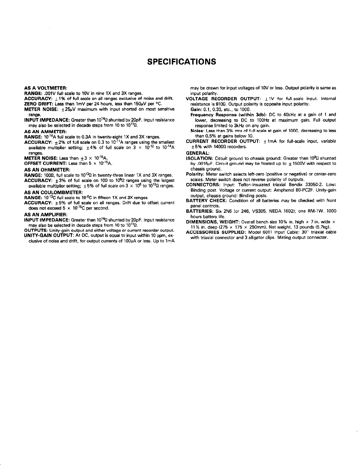
SPECIFICATIONS
AS A VOLTMETER:
RANGE: .OOlV full scale to 1OV in nine’lX and 3X ranges.
ACCURACY: f 1% of full scale on all ranges exclusive of noise and drii.
ZERO DRIFT: Less than Im” per 24 hours, Ikss than 150@ per OC.
METER NOISE: *25&J maxim”m with input shoned on most sensitive
IN?~?iMPEDANCE: Greater than lo’% shunted by2OpF. Input resistance
AS iN AMMETER:
RANGE: lCr14A full scale to 0.3A in twenty-eight 1X and 3X ranges.
ACCURACY: 12% of full scale on 0.3 to 10”A ranges using the mallest
available multiplier setting; *t4% of full scale on 3 x lo-l2 fo 10-14A
ranoes.
METER NOISE: Less than f3 x 10-16A.
OFFSET CVRRENT: Lens than 5 x 10-15A.
AS AN OHMMETER:
RANQE: 7000, full scale to 10% in twent+hree linear IX and 3X ranges.
ACCURACY: *3% of full scale on 100 to l@Q ranges using the largest
available multiplier stting; f5% of full scale on 3 x 10⁹ to 1O’jn ranges.
AS AN COULOMBMETER:
RANGE: lo-‘? full scale to 10dC in fifteen IX and 3X ranges.
ACCURACY: f5% of full scale on all ranges. Dritt due fo offset current
does no, exceed 5 x 10.=C per second.
AS AN AMPLIFIER:
tNPUT IMPEDANCE: Greater than 10’40 shunted by2OpF. input resistance
may a,so be ~&cted in decade steps from 10 fo lO”O.
OUTPUTS: Unitygain output and either voltage or cment recorder o”tp”t.
UNITY-QAIN OUTPUT: At DC, o”tp”t is equal to input within 10 ppm. ex-
clusive of noise and drib?. for o”tp”t currents of lOO@ or less. Up 10 ImA
may be drawn for input voltages of 10” or less. Output polarity is same as
input p&dry.
VOLTAGE RECORDER OUTPUT: *lV for full-scale input. Internal
resistance is g1M1. Output polarity is opposite input polarity.
Gain: 0.1. 0.33, a.. to 1000.
Frequmw Response lwithin 3db): DC to 40kHr 81 a gain of 1 and
lo&, &e&g to DC to 1OOHz at maximum gain. Full o”tp”t
response limited to 3kHz on any gain.
Noise: Less than 3% ms of full scale at gain of 1000. decreasing 10 less
than 0.5% ar gains below 10.
CURRENT RECORDER OUTPUT: i ImA for full-scale input. variable
f6% wtih 14OOll recorders.
GENERAL
ISOLATION: Circuit ground to chassis ground: Greater than l@Q shunted
by .0016~F. Circuit ground may be floated up to f 15OOV with wpecf to
chassis ground.
Polarity: Meter *witch seIects lefvzero Ipositive or negative) or center-zero
scales. Meter witch does nof reverse polarity of o”fp”tS.
CONNECTORS: Input: Teflon-insulated tdaxial Bendix 33050-Z. Low:
Binding post. Voltage or currem o”tp”t: Amphenol 60.PCZF. Unity-gain
o”tp”1, chassis ground: Binding posts.
BATTERY CHECK: Condition of all baneries may be checked with front
paw co”trok.
BATTERIES: Six 2N6 lor 246. VS306. NEDA 16021: one RM-1W. 1000
DIMENSIONS. WEIGHT: Overall bench size 10% in. high x 7 in. wide x
11 ‘h in. deep 1276 x 175 x 2gOmm). Net weight. 13 pounds l57kgl.
ACCESSORIES SUPPLIED: Model 6011 Input Cable: 30” triaxial cable
with friaxial connector and 3 alligator clips. Mating o”tp”f connector.
Page 4

Page 5
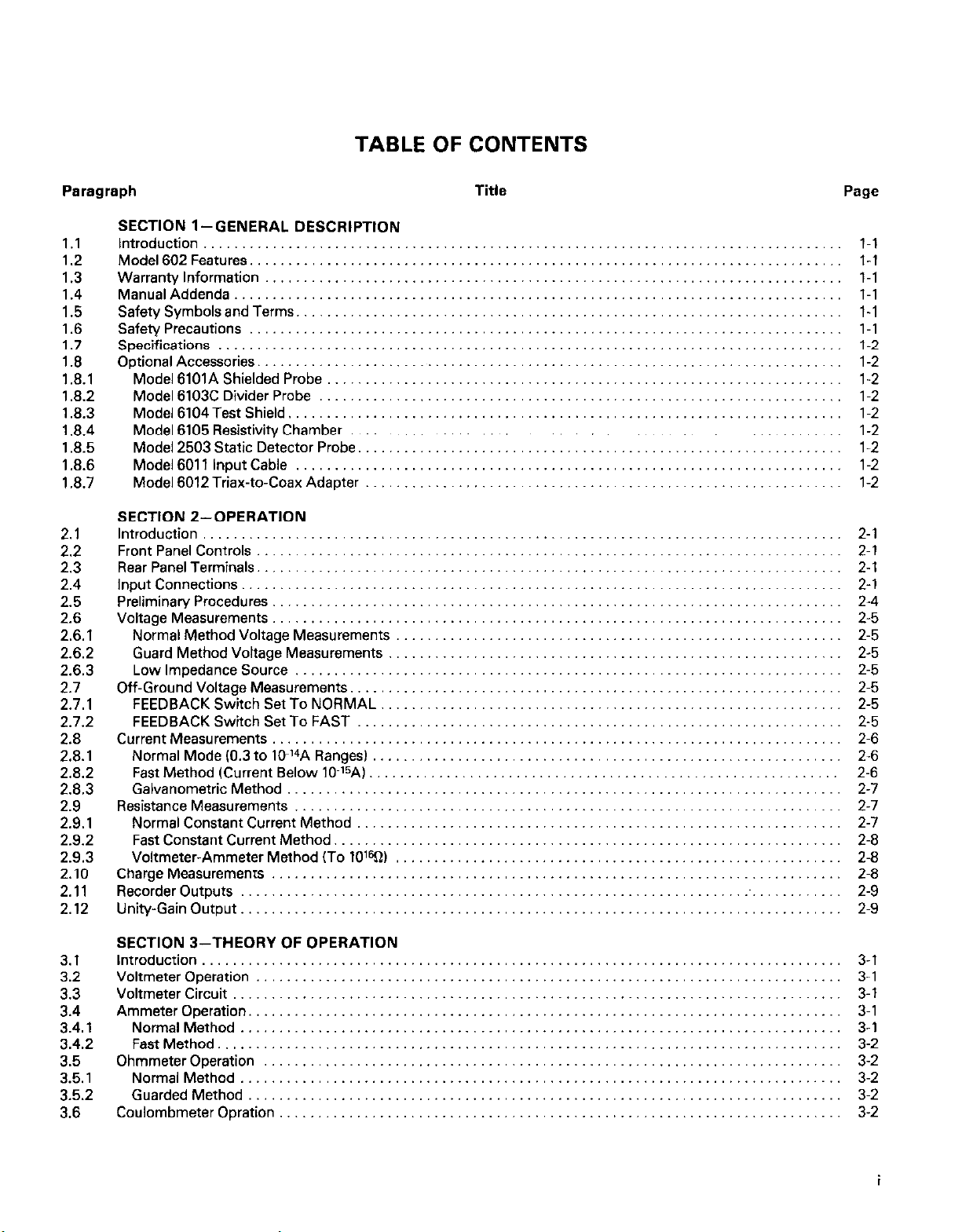
TABLE OF CONTENTS
Paragraph
SECTION l-GENERAL DESCRIPTION
1.1
1.2
1.3
1.4
1.5
1.6
1.7
1.8
1.8.1
1.82
1.8.3
1.8.4
1.8.5
1.8.6
1.8.7
2.1
2.2
2.3
2.4
2.5
2.6
2.6.1
2.6.2
2.6.3
2.7
2.7.1
2.7.2
2.8
2.8.1
2.6.2
2.8.3
2.9
2.9.1
2.9.2
2.9.3
2.10
2.11
2.12
Introduction ...........................
Model 602 Features. ....................
Warranty Information ...................
ManualAddenda
Safety Symbols and Terms. ..............
Safety Precautions
Specifications .........................
Optional Accessories. ...................
SECTION Z-OPERATION
Introduction ..........................
Front Panel Controls ...................
Rear Panel Terminals. ..................
Input Connections .....................
Preliminary Procedures. ................
Voltage Measurements. ................
Off-Ground Voltage Measurements .......
Current Measurements .................
Resistance Measurements ..............
Charge Measurements .................
Recorder Outputs .....................
Unity-Gain Output .....................
.......................
.....................
Model 6101A Shielded Probe ...........
Model 6103C Divider Probe
Model 6104Test Shield. ...............
Model 6105 Resistivity Chamber ........
Model 2503 Static Detector Probe.
Model 6011 Input Cable ...............
Model 6012 Triax-to-Coax Adapter ......
Normal Method Voltage Measurements
Guard Method Voltage Measurements
Low Impedance Source ..............
FEEDBACK Switch Set To NORMAL ...
FEEDBACK Switch Set To FAST ......
Normal Mode IO.3 to lO~‘4A Ranges) ....
Fast Method (Current Below lo-=A) ....
Galvanometric Method ...............
Normal Constant Current Method ......
Fast Constant Current Method. ........
Voltmeter-Ammeter Method (To 10%)
............
......
................
................
................
................
................
................
................
................
................
................
................
................
................
.............
.............
.............
.............
.............
.............
.............
.............
.............
.............
.............
.............
.............
.............
.............
.............
.............
.............
.............
Title Page
.........
...... ..
.........
.........
.........
.........
.........
.........
.........
.........
1-l
l-l
l-l
l-l
l-1
l-l
1-2
1-2
1-2
1-2
1-2
1-2
1-2
1-2
1-2
2-1
2-l
2-l
2-l
2-4
2-5
2-5
2-5
2-5
2-5
2-5
2-5
2-6
2-6
2-6
2-7
2-7
2-7
2-8
2-8
2-8
2-9
2-9
......
......
......
......
......
......
......
......
......
......
......
......
......
......
......
......
......
.............
.............
.............
.............
.............
.............
.............
.............
.............
.............
.............
......
......
......
......
......
......
......
......
......
......
......
......
......
......
......
......
......
......
......
......
3.1
3.2
3.3
3.4
3.4.1
3.4.2
3.5
3.5.1
3.5.2
3.6
SECTION 3-THEORY OF OPERATION
Introduction ..........................
Voltmeter Operation ...................
Voltmeter Circuit ......................
Ammeter Operation. ...................
Normal Method .....................
Fast Method. .......................
Ohmmeter Operation ..................
Normal Method .....................
Guarded Method ....................
Coulombmeter Opration ................
......
......
......
......
......
......
......
......
......
......
......
,,....
......
......
......
......
......
.,....
.............
.............
.............
.............
.............
.............
.............
.............
.............
......
......
3-l
3-1
3-l
3-1
3-l
3-2
3-2
3-2
3-2
3-2
Page 6
4.1
4.2
4.2.1
4.2.2
4.3
4.4
4.5
4.6
4.7
4.8
4.9
4.10
4.10.1
4.10.2
4.10.3
4.10.4
4.11
4.12
4.13
4.14
4.14.1
4.14.2
4.15
4.16
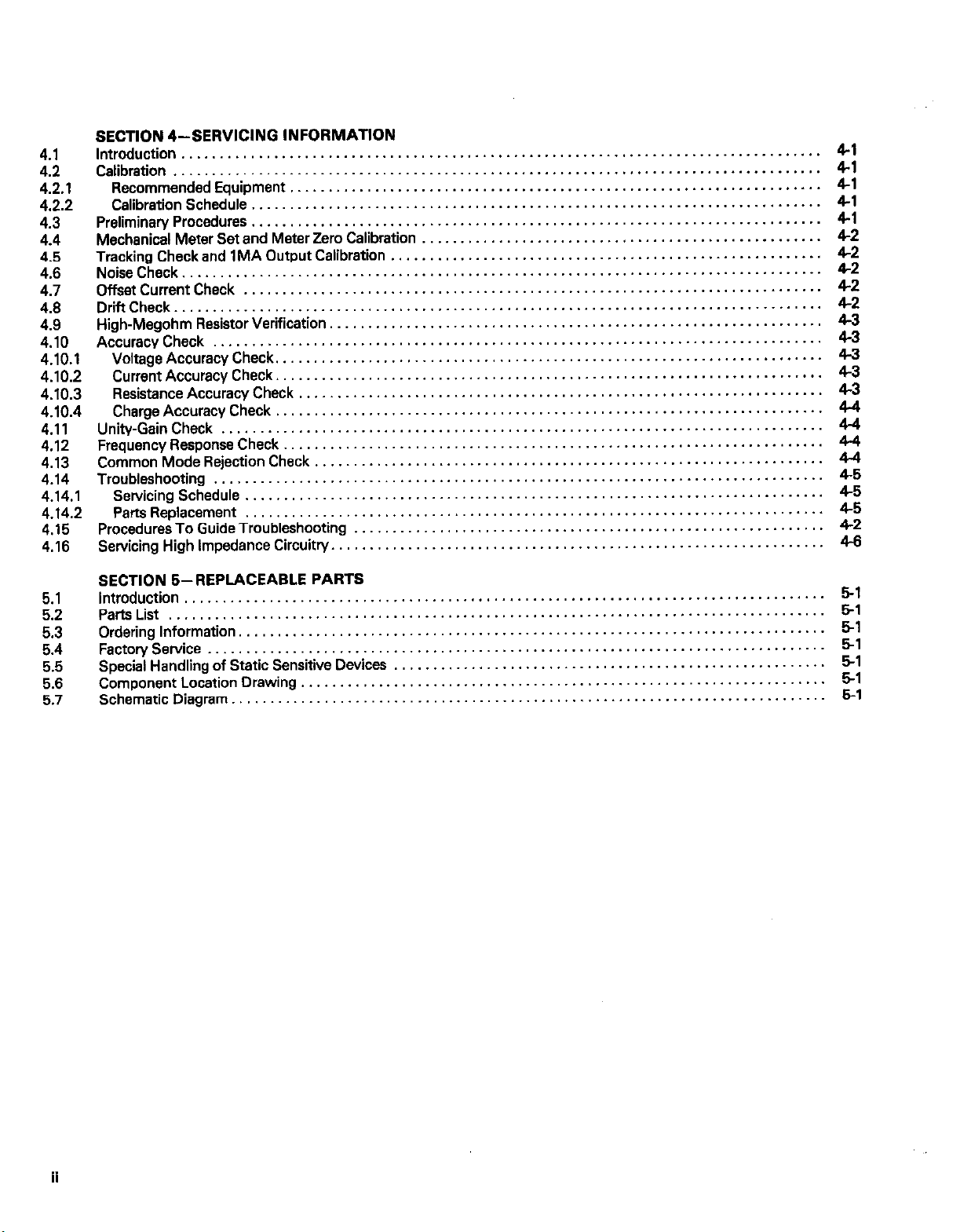
SECTION 4--SERVICING INFORMATION
Introduction ...................................................................................
Calibration
RecommendedEquipment
....................................................................................
.....................................................................
CalibrationSchedule ..........................................................................
Preliminary Procedures
Mechanical Meter Set and Meter Zero Calibration
Tracking Check and 1MA Output Calibration
..........................................................................
....................................................
........................................................
NoiseCheck ...................................................................................
OffsetCurrentCheck
DrinCheck
....................................................................................
High-Megohm ResistorVerification.
AccuracyCheck
...........................................................................
...............................................................
...............................................................................
VoltageAccuracyCheck .......................................................................
CurrentAccuracyCheck .......................................................................
ResistanceAccuracyCheck
....................................................................
ChargeAccuracyCheck .......................................................................
Unity-GainCheck
..............................................................................
FrequencyResponseCheck ......................................................................
CommonModeRejectionCheck ..................................................................
Troubleshooting ...............................................................................
Servicing Schedule ...........................................................................
Par&Replacement
Procedures To Guide Troubleshooting
Servicing High Impedance Circuitry
...........................................................................
.............................................................
................................................................
41
4-l
4-l
4-l
4-l
4-2
4-2
4-2
z
4-3
4-3
43
2
4-4
zl
4.4
45
z
4.2
4-6
5.1
5.2
5.3
5.4
5.5
5.6
5.7
SECTION S-REPLACEABLE PARTS
Introduction
...................................................................................
PartsList .....................................................................................
OrderingInformation ............................................................................
FactoryService ................................................................................
Special Handling of Static Sensitive Devices
ComponentLocationDrawing
....................................................................
........................................................
SchematicDiagram.........................,.,.............,,..,............................... o-1
5-l
5-l
51
5-l
51
51
r*
ii
Page 7
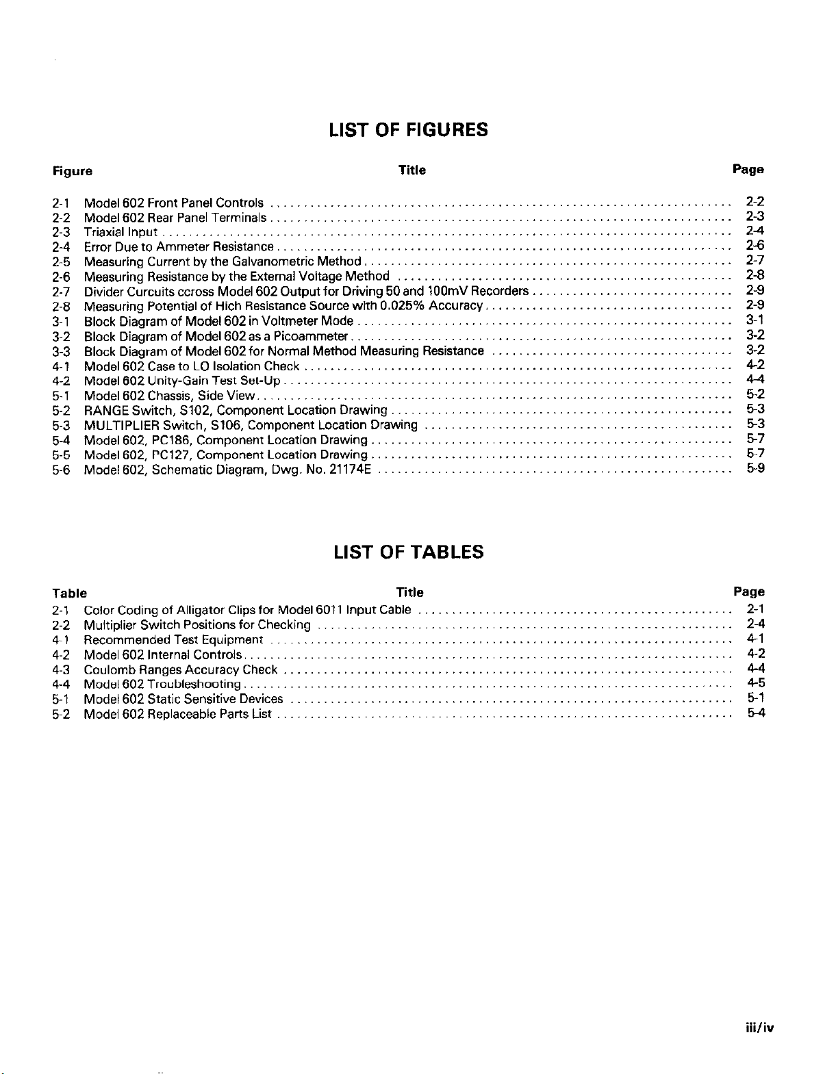
LIST OF FIGURES
Figure
Model 602 Front Panel Controls
2-1
Model 602 Rear Panel Terminals
2-2
Triaxiallnput ..........................................................
2-3
Error Due to Ammeter Resistance.
2-4
Measuring Current by the Galvanometric Method,
2-5
Measuring Resistance by the External Voltage Method
2-6
2-7 Divider Curcuits ccross Model 602 Output for Driving 50 and 10OmV Recorders
Measuring Potential of Hich Resistance Source with 0.025% Accuracy.
2-8
Block Diagram of Model 602 in Voltmeter Mode
3-1
Block Diagram of Model 602as a Picoammeter
3-2
Block Diagram of Model 602for Normal Method Measuring Resistance
3-3
4-l Model 602 Case to LO Isolation Check
Model 602 Unity-Gain Test Set-Up.
4-2
Model 602 Chassis, Side View.
5-1
RANGE Switch, S102, Component Location Drawing
5-2
MULTIPLIER Switch, S106, Component Location Drawing
5-3
Model 602, PC186, Component Location Drawing
5-4
Model 602, PC127, Component Location Drawing
5-5
Model 602, Schematic Diagram, Dwg. No. 21174E
5-6
.......................................... ................
..........................................
........................................
..............................
.....................................
....................................... ................
...........................................
Title
...........................
.......................
.........
............................. ................
.........
........................
...................
...........................
...........................
..........................
LIST OF TABLES
...
................
................
................
................
................
................
................
................
................
................
................
................
................
................
................
................
Page
.........
......... 2-3
......... 2-4
......... 2-6
......... 2-7
......... 2-8
......... 2-9
......... 2-9
.........
......... 3-2
......... 3-2
......... 4-2
......... 4-4
.........
......... 53
......... 53
.........
......... 5-9
2-2
3-l
5-2
57
5-7
Table
2-l Color Coding of Alligator Clips for Model 6011 Input Cable ...
2-2 Multiplier Switch Positions for Checking
4-1 Recommended Test Equipment .........................
4-2 Model 602 Internal Controls.
4-3 Coulomb Ranges Accuracy Check
4-4 Model 602 Troubleshooting.
5-l Model 602 Static Sensitive Devices
5-2 Model 602 Replaceable Parts List
............................
............................
..................
.......................
......................
........................
Title
......
......
......
......
......
......
......
......
......
......
......
......
......
..,...
Page
2-l
2-4
4-l
4-2
4-4
4-5
5-l
54
iii/iv
Page 8

Page 9
SECTION 1
GENERAL DESCRIPTION
1.1 INTRODUCTION 1.3 WARRANTY INFORMATION
The Keithley Model 602 Electrometer is a completely solid-
state, battery operated instrument, which measures a wide
range of DC voltage, current, resistance and charge. The
Model 602’s input resistance of greater than 10’4R is the
result of extensive instrument development with high input
impedance transistors. The Model 602 has all the capabilities
of conventional VTVMs, but can also make more measure-
ments without loading circuits.
The Model 602 has nine voltage ranges from O.OOlV full scale
to lOV, 28 current ranges from 10’4A full scale to 0.3A. 23
linear resistance ranges from 1000 full scale to 1OtQ. and 15
charge ranges from lo-‘SC full scale to lo-aC.
The Model 602 offers complete line isolation and excellent
off-ground measuring capability. Up to 1500V may be applied instrument which occur after the printins o! this manual will
between the input low terminal and the case, and stage be found on an addendum sheet included .-:ith this manual.
operation is assured with the case grounded. A triaxial con- Be sure to review these changes before ar:en:$ing to operate
nectar allows complete guarding of the high impedance input or service the instrument.
terminal.
The Model 602 employs matched insulated-gate field-effect
transistors followed by transistor differential amplifier stages
and a compliritentary-output stage. A large amount of
negative feedback is used for stability and accuracy.
1.2 MODEL 602 FEATURES
1. The Model 602 has excellent zero stability which permits
accurate measurements with minimal adjustment. Short
term zero drift is less than 50& per hour. Zero offset due
to temperature change is less than 15O/rV per OC after 30
minute warm-up period. This offset, however, can easily
be compensated for with the front panel zero controls.
2. Fast warm-up is an inherent characteristic of the Model
602. It can be operated 30 minutes after warm-up on the
most sensitive range and almost immediately on less sensi-
tive ranaes.
3. Low offset current 5 X lo-IsA, minimizes zero offset with
high source resistance and permits maximum resolution
when measuring current and charge.
4. The 1000 hour life of the batteries enables usage in long
term experiments without interruptions for recharging.
Battery life is maintained even when the 1OmA recorder
output is used. For further convenience, battery condition
is readily checked on the panel meter.
5. Excellent overload protection without degradation of performance is obtained by use of a unique input circuit. The
Model 602 Electrometer will withstand damage and has
good recovery.
Warranty information may be found inside the front cover of
this manual. Should it become necessary to exercise the
warranty, contact your nearest Keithley representative or the
factory to determine the correct course of action. Keithley
Instruments maintains service facilities in the United States,
West Germany, Great Britain, France, the Netherlands,
Switzerland, and Austria. Information concerning the appli-
cation, operation, or service of your instrument may be
directed to the applications engineer at any of these locations. Check the inside front cover of this manual for addresses.
1.4 MANUAL ADDENDA
Information concerning improvements or changes to the
1.5 SAFETY SYMBOLS AND TERMS
The following safety symbols and terms are used in this
manual or found on the Model 602.
The symbol
should refer to the operating instructions in this ;nanual.
The symbol
tential of 1OOOV or more may be present on the terminaltsl.
Standard safety precautions should be observed when such
dangerous voltages are encountered.
The WARNING heading in this manual explains dangers that
could result in personal injury or death.
The CAUTION heading in this manual explains hazards that
could damage the instrument.
1.6 SAFETY PRECAUTIONS
1. This instrument is intended for use by qualified personnel
who recognize the shock hazards and are familiar with the
safety precautions required to avoid possible injury. Read
over the manual carefully before operating this instrument.
2. Excercise extreme caution when a shock hazard is present
at the instrument’s input. The American National
Standards Institute (ANSI) states that a shock hazard ex-
ists when voltage levels greater than 30V rms or 42.4V
peak are present. A good safety practice is to expect that
hazardous voltage is present in any unknown circuit before
measuring.
on the instrument indicates that the user
A
#
on the instrument indicates that a po-
l-l
Page 10
3. Inspect the test leads for possible wear, cracks or breaks
before each use. If any defects are found, replace with test
leads that have the same measure of safety as those supplied with the instrument.
4. For optimum safety do not touch the test leads or the
instrument while power is applied to the circuit under test.
Turn the power off and discharge all capacitors, before
connecting or disconnecting the instrument.
5. Do not touch any object which could provide a current
path to the common side of the circuit under test or power
line (earth) ground. Always make measurements with dry
hands while standing on a dry, insulated surface, capable
of withstanding the voltage being measured.
6. Exercise extreme safety when testing high energy power
circuits (AC line or mains, etc). Refer to the operating
section.
7. Do not exceed the instrument’s maximum allowable input
as defined in the specifications and operation section.
1.7 SPECIFICATIONS
Detailed Model 602 specifications may be found immediately
preceding this section.
Three-Terminal Connections-The GUARD output on the
Model 602 Electrometer can be used for resistance
measurements where the effects of cable capacitance may be
significant. Connect the unknown between INPUT and EXT
terminals. Connect the EXT terminal to the GUARD output
on the electrometer. Use the electrometer in fast mode for
ohms measurement.
I.E.4 Model 6105 Resistivity Chamber
The Model 6105 is a guarded test fixture for measurement of
surface and volume resistivities. The chamber is designed in
accordance with ASTM Standard Method of Test for Electrical Resistance of Insulated Materials, D257-66. The Model
6105 can be used in conjunction with an electrometer and
voltage supply.
Resistivity can be determined by measuring the current
through a sample with a known voltage impressed. The
measurement can be made most conveniently when a set of
electrodes are used which can be calibrated in terms of
surface or volume resistivity. The Model 6105 has been
designed for use with a Keithley electrometer and an optional
high voltage supply such as the Model 247.
1.8 OPTIONAL ACCESSORIES
The following optional accessories can be used with the
Model 602 to provide additional convenience and versatility.
1.8.1 Model 8lOlA Shielded Probe
The Model 6010A is a shielded cable with a needle point
probe and 30 inches of low noise cable terminated by a UHF
connector.
I.E.2 Model 8103C Divider Probe
The Model 6013C is a shielded cable with a needle point
probe and 30 inches of low noise cable terminated by a UHF
connector. The probe includes a 1OOO:l voltage divider with a
4.5 X 1OW input resistance. Accuracy is f5% at 30kV.
1.8.3 Model 8104 Test Shield
The Model 6104 is a shielded test box for two-terminal or
three-terminal connections. The INPUT terminal is Teflon@
insulated.
Two-Terminal Connections-Resistance measurements
can be made conveniently using the INPUT and GROUND
terminals on the test box. Connect the electrometer to the
BNC output. Use the electrometer in normal mode for ohms
measurement.
1.8.5 Model 2503 Static Detector Probe
Model 2503 is designed to detect voltage due to charge on
relatively small surface areas. Solid coaxial 13mm (% inch)
diameter tube used with 89mm (3% inch) head, 89mm (3%
inch) coupler, 25mm (one inch) adapter and two 90° angle
adapters which may be placed at various junctions along the
tube. It gives a 10,OOO:l & 10% divsion ratio when used with
Model 610C and held 6mm (‘/ inch) away from a charged
plane of at least 13mm (% inch) diameter. Output is a UHF
male plug.
I.E.8 Model 8011 Input Cable
The Model 6011 is a low-noise triaxial cable, 30 inches long,
terminated by three color-coded alligator clips. This cable
mates directly with the triaxial input. The cable is fabricated
using a Keithley connector (P/N CS-141) and low-noise cable
(P/N SC-22).
The Model 6011 may be used for measurements which require a triaxial connection, especially when the input LO is
floated above CASE ground.
I.E.7 Model 6012 Triax-to-Coax Adapter
The Model 6012 is an adapter for mating the triaxial input and
UHF (coax) type connectors. Permits using Models 220,602,
614, 616 and 619 with all Keithley electromete accessories
having UHF type connectors.
l-2
Page 11
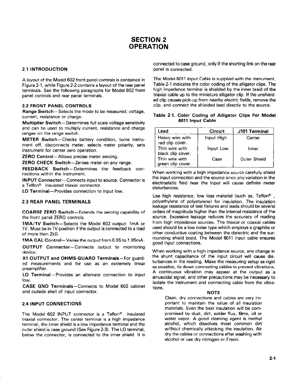
2.1 INTRODUCTION
SECTION 2
OPERATION
connected to case ground, only if the shorting link on the rear
panel is connected.
A layout of the Model 602 front panel controls is contained in
Figure 2-1, while Figure 2-2 contains a layout of the rear panel
terminals. See the following paragraphs for Model 602 front
panel controls and rear panel terminals.
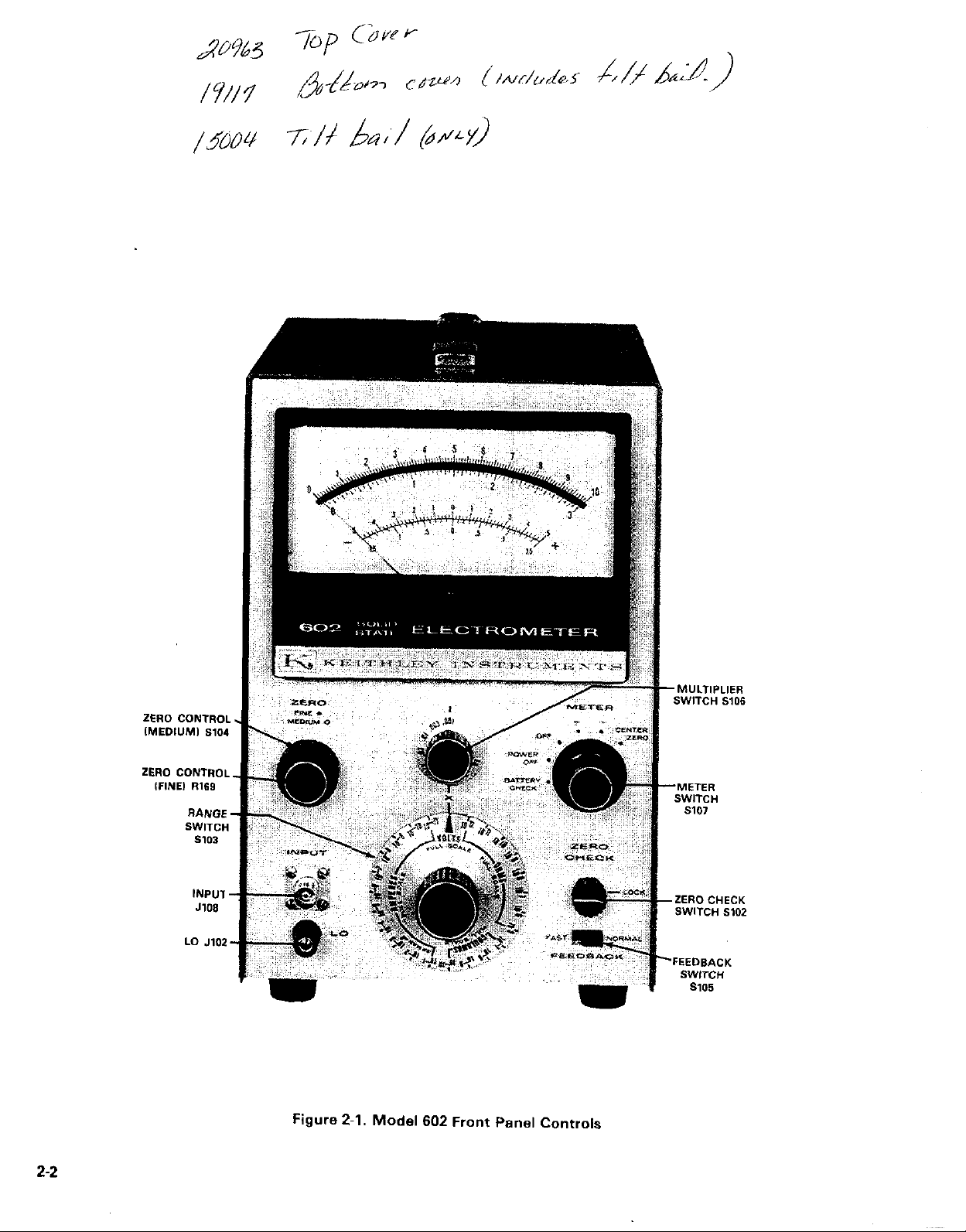
2.2 FRONT PANEL CONTROLS
Range Switch-Selects the mode to be measured: voltage,
current, resistance or charge.
Multiplier Switch-Determines full scale voltage sensitivity
and can be used to multiply current, resistance and charge
ranges on the range switch.
METER Switch-Checks battery condition, turns instrument off, disconnects meter, selects meter polarity, sets
instrument for center zero operation.
ZERO Control-Allows precise meter zeroing.
ZERO CHECK Switch-Zeroes meter on any range.
FEEDBACK Switch-Determines the feedback connections within the instrument.
INPUT Connector-Connects input to source. Connector is
a Teflon” insulated triaxial connector.
LO Terminal-Provides connection to input low.
2.3 REAR PANEL TERMINALS
COARSE ZERO Switch-Extends the zeroing capability of
the front panel ZERO controls.
lMA/IV Switch-Selects the Model 602 output: 1mA or
1V. Must be in 1V position if the output is connected to a load
of more than 2kQ.
IMA CAL Control-Varies the output from 0.95 to 1.05mA.
OUTPUT Connector-Connects output to monitoring
device.
Xl OUTPUT and OHMS-GUARD Terminals-For guard-
ed measurements and for use as an extremely linear
preamplifier.
LO Terminal-Provides an alternate connection to input
low.
CASE GND Terminals-Connects to Model 602 cabinet
and outside shell of input connector.
2.4 INPUT CONNECTIONS
The Model 602 INPUT connector is a TeflonO insulated
triaxial connector. The center terminal is a high impedance
terminal, the inner shield is a low impedance terminal and the
outer shield is case ground (See Figure 2-3). The LO terminal,
below the connector, is connected to the inner shield. It is
The Model 6011 Input Cable is supplied with the instrument,
Table 2-1 indicates the color coding of the alligator clips. The
high impedance terminal is shielded by the inner braid of the
triaxial cable up to the miniature alligator clip. If the unshielded clip causes pick-up from nearby electric fields, remove the
clip, and connect the shielded lead directly to the source.
Table 2-l. Color Coding of Alligator Clips For Modal
8011 Input Cable
Lead
Heavy wire with
red clip cover.
Thin wire with
black clip cover.
Thin wire with
green clip cover.
When working with a high impedance source carefully shield
the input connection and the source since any variation in the
electrostatic field near the input will cause definite meter
disturbances.
Use high resistance, low loss material (such as, Teflon@ ,
polyethylene of polystyrene) for insulation. The insulation
leakage resistance of test fixtures and leads should be several
orders of magnitude higher than the internal resistance of the
source. Excessive leakage reduces the accuracy of reading
from high impedance sources. The triaxial or coaxial cables
used should be a low noise type which employs a graphite or
other conductive coating between the dielectric and the sur-
rounding shield braid. The Model 6011 input cable ensures
good input connections.
When working with a high impedance source, any change in
the shunt capacitance of the input circuit will cause disturbances in the reading. Make the measuring setup as rigid
as possible, tie down connecting cables to prevent vibrations.
A continuous vibration may appear at the output as a
sinusoidal signal, and other precautions may be necessary to
isolate the instrument and connecting cable from the vibra-
tions.
Clean, dry connections and cables are very important to maintain the value of all insulation
materials. Even the best insulation will be com-
promised by dust, dirt, solder flux, films, oil or
water vapor. A good cleaning agent is methyl
alcohol, which dissolves most common dirt
without chemically attacking the insulation. Air
dry the cables or connections after washing with
alcohol or use dn/ nitrogen or Freon.
Circuit
Input High Center
Input Low
Case Outer Shield
NOTE
JIOI Terminal
Inner
2-1
Page 12
2-2
Figure 2-l. Model 602 Front Panel Controls
Page 13

Figure 2.2. Model 602 Rear Panel Terminals
2-3
Page 14

batteries checked by position. If the reading for any battery
other than 8203 is below two-thirds, replace all batteries except for 8203. If the reading for B203 is less than two-thirds
full scale, replace it. Note, that, new batteries may cause the
Model 602 to drift more than normal for at least 72 hours due
to change in battery terminal voltage.
Set the controls as follows:
ZERO CHECK Button LOCK
Range Switch VOLTS
Multiplier Switch
FEEDBACK Switch
METER Switch
1
NORMAL
POWER OFF
Figure 2-3. Triaxial Input
For low impedance measurements (below 1080 or above
lO*RA) unshielded leads may be used. When the Model 602
is used on the most sensitive current ranae with the FEED-
BACK switch at FAST, some insulators kuch as Teflon” )
may produce random signals which show up as erratic meter
deflections. Insulation used in the Model 602 is carefully
selected to minimize these spurious signals.
If a well shielded chamber and a well made high impedance
transfer switch is available, it is advantageous to connect the
Model 602 to the circuit only when a reading is being made.
In some cases, the offset current can charge the external test
circuitry. One example of this occurs when measuring a
capacitor’s leakage resistance by observing the decay of ;he
terminal voltage. If the leakage current is less than the offset
current (less than 5 X 10.‘5A there may be no decay of the
terminal voltage when the Model 602 is left connected across
the capacitor’s terminals.
NOTE
Keep the shield cap on the INPUT connector
when the Model 602 is not in use.
The Model 6012 Triaxial-to-Coaxial Adapter permits use of
cables and accessories with the Model 602 by adapting the
triaxial INPUT connector to the UHF coaxial type.
CAUTION
The Model 6012 connects low to case
ground. The Modal 602 cannot be used offground when using the Model 6012. The instrument’s cabinet will be at the same
potential as the input low.
2.5 PRELIMINARY PROCEDURES
Check battery condition by holding the METER switch in the
BATTERY CHECK position. Rotate the multiplier switch
through the ,001 to 0.1 positions and observe the meter
readings. The meter should read at least two-thirds of full
scale in each multiplier switch position. Table 2-2 shows the
Table 2-2. Multiplier Switch Positions for Checking
Conditions of Batteries
Multiplier Position
,001
1
1 tc
1. Turn the METER switch
I CENTER ZERO. Within ten
seconds, the mater needle should con?,.? ‘to the center position. If not, adjust the mater zero with the MEDIUM and
FINE ZERO controls. Normally, there is no need to use the
COARSEZERO
‘.
NOTE
Using the center zero scales decreases accuracy
0.5% because the scale span is reduced.
2. After a few moments increase the voltage sensitivity by
advancing the multiplier switch. Continue zeroing with the
FINE ZERO control.
3. After long periods of storage or after an overload, the
Model 602 may drift excessively. The input transistors are
insensitive to mechanical shock; however, a severe input
overload may cause a zero offset. This is corrected with
the ZERO controls. Drifting can occur for several hours.
NOTE
If the Model 602 has been stored for some time,
the offset current will exceed the specification
when first used, then decrease to below the
specified amount after one or two hours of use.
This is an inherent characteristic of the input
transistors; the instrument is not faulty.
4. Although the offset current of the Model 602 is below that
found in conventional voltmeters, it can be observed on
the meter. The current charges the input capacitance, and
the Model 602 appears to drift when the input is open. Use
the ZERO CHECK button to discharge the charge build-up.
Depressing the ZERO CHECK button removes all signal
from the amplifier and reduces the input impedance
between HI and LO terminals of the INPUT connector to
10MR.
2-l
Page 15

5. Follow the procedures in paragraphs 2.6 to 2.10 for
measuring voltage, current, resistance and charge.
NOTE
When using multiplier switch settings of 10, 3
and 1 in the voltage, current, resistance and
charge measuring modes, make sure the OUT-
PUT switch is set to 1V if the output is connected to a load of more than 2kR. Otherwise,
the meter will not read full scale signals correct-
ly. When the output is loaded, this effect is not
present.
2.6 VOLTAGE MEASUREMENTS
Set the controls as follows:
ZERO CHECK Button LOCK
Range Switch VOLTS
Multiplier Switch
10
FEEDBACK Switch FAST
METER Switch CENTER ZERO
Connect the unknown voltage to the high (center) terminal of
the INPUT connector and to the OHMS GUARD terminal on
the rear panel. Use the LO terminal as a guard between circuit
high and low. Unlock the ZERO CHECK button. Set the
METER switch to + or -, as necessary. Recheck zero setting
after increasing sensitivity. To make off-ground voltage
measurements, see paragraph 2.7.
The Model 602 can be used to measure voltages. In the normal method (FEEDBACK switch at NORMAL) the unknown
voltage is connected to the INPUT connector. Input impedance with the range switch in the VOLTS position is
10%. 2OpF.
To reduce the effects of input cable capacity, use the fast
method to measure the voltage. Set the FEEDBACK switch
at FAST and drive the inner shield of the cable with the Xl
OUTPUT which is connected to the LO terminal in the FAST
position, A guarded circuit is possible this way. To reduce
stray pick-up when making routine measurements fix.
measuring from low impedance sources1 the range resistors
or capacitors may be used to shunt the input. Accessory
probes extend the Model 602’s range to 1OkV.
NOTE
Locking the ZERO CHECK switch places 1OMB
between input high and low, which may temporarily cause instability in e.ome types of high
impedance sources.
2.6.1 Normal Method Voltage Measurements
Set the controls as follows:
ZERO CHECK Button LOCK
Range Switch VOLTS
Multiplier Switch 10
FEEDBACK Switch NORMAL
METER Switch CENTER ZERO
Connect the unknown voltage to the high (center) terminal of
the INPUT connector and to the OHMS GUARD terminal on
the rear panel. Use the LO terminal as a guard between circuit
high and low. Unlock the ZERO CHECK button. Set the
mater switch to + or -, as necessary. Increase sensitivity with
the multiplier switch. Recheck zero setting after increasing
sensitivity. To make off-ground voltage measurements, see
paragraph 2.7.
2.6.3 Low Impedance Sources
To decrease input resistance, set the FEEDBACK switch to
NORMAL and the range switch to one of the AMPERES
ranges. The input resistance is now the reciprocal of the current range. For instance, to obtain an input resistance of
lo%, set the range switch to the 10.rA range Set the full
scale voltage range with the multiplier switch. Operating procedures are the same as paragraph 2.6.1. With reduced input
resistance, the Model 602 will not be deflected off scale by
stray fields when the input is left open.
2.7 OFF-GROUND VOLTAGE MEASUREMENTS
The Model 602 can measure an unknown voltage whose low
impedance terminal is up to 1500V off-ground. Safe opera-
tion of the Model 602 is ensured by grounding the case (see
paragraph 2.6).
CAUTION
Operating the Model 602 more than 16OOV
off-ground may permanently damage the
instrument. Isolation between circuit low
and ground may break down somewhere in
the instrument. Since these breakdowns
are very difficult to locate, it might not be
possible to float the instrument safely
again.
2.7.1 FEEDBACK Switch Set To NORMAL
Disconnect the shorting link between LO and CASE
GROUND terminals on the rear panel. Make sure the Model
602 case is securely connected to an earth ground, and that
the low of the unknown voltage is less than 1500V off-
ground. Connect the unknown voltage directly to the INPUT
connector. Operate the Model 602 as described for normal
method voltage measurements.
2.6.2 Guard Method Voltage Measurement
This method reduces the effects of input cable capacity with
very high impedance source.s and allows guarded voltage
measurements.
2.7.2 FEEDBACK Switch Set To FAST
Disconnect the shorting link between the LO and CASE
GROUND terminals on the rear panel. Make sure the Model
602 case is securely connected to an earth ground, and that
2-5
Page 16

the low of the unknown voltage is less than 1500V offground. Connect the high of the unknown voltage to the
center terminal of the INPUT connector. Connect the low to
the OHMS GUARD terminal. Use the LO terminal or inner
shield of the INPUT connector as a guard. Operate the Model
602 as described for fast method voltage measurements.
WARNING
If the output is used for recording when the
Model 602 is off-ground in the normal or
fast mode, make sure the shell of a mating
plug to the OUTPUT connector is not connected to either pin in the connector. Also.
the recorder output will be off-ground.
WARNING
Use only an insulated blade screwdriver to
adjust the COARSE ZERO switch and 1 MA
CAL control when floating the Model 602.
An ordinary screwdriver could short the circuit low to case ground, creating a shock
hazard and damaging the external circuitry.
2.8 CURRENT MEASUREMENTS
The Model 602 can measure current three ways.
1. In the normal method luseable on any range) the current is
determined by measuring the voltage drop across a resistor
shunting the amplifier input. This method is useful when
low noise is more important than fast response speed or if
some damping is needed.
2. In the fast method (for use only below the lC-‘5A range)
the shunt resistor is between the amplifier output and input
in the feedback loop. This circuit largely neutralizes the effect of input capacity and greatly increases the response
speed. Also, the input voltage drop is reduced to a maximum of 1mV on any range.
3. For galvanometric current measurements, the Model 602
acts as a null indicator between a known current and the
unknown current source.
Rise time varies primarily with the current range, the input
capacity and the method used. Wifh the FEEDBACK switch
in the FAST position, the rise time on the most sensitive
range is less than 2sec and on the l@‘A range, less than
3msec. Given a choice, it is better to place the Model 602
nearer to the current source than fo the data reading instrument. Transmining the input signal through long cables
slightly decreases the response speed and greatly increases
noise due to cable capacitance.
To measure from a source with both terminals off-ground in
either method, remove the link between the LO and CASE
GROUND terminals on the rear panel. Connect the unknown
current fo the INPUT connector. The source must be less
than & 15OOV off-ground (see paragraph 2.7 and Figure 2-4).
I
Is = Es/R*
ERROR = 1%. 1.
?&ERROR = E,,/E, Y Km
IF E,N< <Es. THEN IM = Is.
NOTE: CURRENT SDURCES MAY SE CONSIDERED A
VOLTAGE ,E, IN SERIES WITH A RESISTANCE ii?). THE
CURRENT WlTH THE AMMETER SHORT CIRCUITED IS
I=E/R. WITH THE SHORT REMOVED, THE EFFECTIVE
INPUT RESISTANCE OF THE AMMETER
WITH THE SOURCE RESfSTANCE (RI.
Lz-
11
IR,,l IS IN SERIES
I
Figure 2-4. Error Due to Ammeter Resistance
2.8.1 Normal Mode (0.3 to 10’4A Ranges1
Set the controls as follows:
ZERO CHECK Button LOCK
Range Switch lo-’ AMPERE
Multiplier Switch
1
FEEDBACK Switch NORMAL
METER Switch CENTER ZERO
Connect the unknown current to the high terminal (center
terminal) of the INPUT connector and use the low terminal
(inner shield) for the return path. Unlock the ZERO CHECK
button. Set the METER switch to + or -, as necessary. Increase the sensitivity with the range switch and the multiplier
switch. Do not set the multiplier switch higher than 3 for
range switch settings 103 and above. Check zero with the
ZERO CHECK button.
The full scale current range is mulriplier switch setting times
range switch setting. Use the smallest multiplier switch setting possible to minimize input voltage drop and thus obtain
the best accuracy. The input resistor varies with the range
switch setting, from 100, to l@‘A to 101% for 1011A. The full
scale input voltage drop is equal to the multiplier switch setting.
2.8.2 Fast Method (Current Below 10’6A)
Set the controls as follows:
ZERO CHECK Button LOCK
Range Switch 106 AMPERES
Multiplier Switch 1
FEEDBACK Switch FAST
METER Switch
CENTER ZERO
Connect the unknown source to the INPUT connector and
lock the ZERO CHECK button. Set the METER switch to t
or -, as necessary. Increase the sensitivity with the range
switch and the multiplier switch. Check zero only with the
ZERO CHECK button. Do not short the input, because this
will remove the feedback from the circuit.
2-6
Page 17

The full scale current range is the multiplier switch setting
times the range switch sening. When selecting the multiplier
switch setting, remember smaller settings permit lower
source resistances, and larger senings improve instrument
zero stability.
With the fast method, the input drop is reduced and the
response speed is increased at least 100 times. However, the
following safety precautions should be observed.
1. The internal impedance of the unknown current source
should not be less than 0.1 of the value of the feedback
resistor being used. Otherwise, adequate feedback voltage
cannot be developed at the input and zero instability
results. The feedback resistor value is the reciprocal of the
AMPERES range of the range switch.
2. The low side (pin No. 2) of the OUTPUT connector is no
longer connected to the low side of the INPUT connector.
Therefore, do not use a grounded recorder. As an alternative use the unity-gain output. (See paragraph 2.12).
3. Use, with caution, the fast method to measure capacitor
leakage. A very stable voltage supply must be used. Connecting a capacitor to the input changes the circuit to a
differentiator, resulting in extreme sensitivity to very small
voltage transients and an increase in meter noise.
2.8.3 Galvanometric Method
Operate the Model 802 as a picoammeter in the fast method.
Use an accurate reference current source such as the
Keithley Model 261 to buck out the unknown current source.
Connect as shown in Figure 2-5.
Set the METER switch to CENTER ZERO and use the higher
current ranges. Adjust the buck out current to indicate null on
the Model 602. Increase the Model 602 sensitivity as needed.
When the Model 602 is as close to null as possible, the
unknown current is equal to the algebraic sum of the Model
261 sening and the Model 602 current reading.
NULL
DETECTOR
2.9 RESISTANCE MEASUREMENTS
The Model 802 can measure resistance by two methods.
In the constant current method, the Model 602 measures
the voltage drop across the unknown sample as a known,
constant current flows through it. The voltage drop is proportional to the resistance of the sample. In this method
the Model 602 can be used in one of two different modes:
normal or fast. The normal mode is recommended for use
from 100 to 101’0. Above 101%, the fast method is preferred. It results in faster response speed and also nullifies
leakage across the Model 602 input, since the potential
across the input terminal is small.
In the preceding method, the voltage across the sample
cannot be arbitrarily set. In some cases, as in measuring
capacitor leakage, this results in excessively long testing
time. In the voltmeter ammeter method, the Model 602 is
used as a picoammeter. The unknown resistance sample is
connected to an external known voltage source and the
current through the sample is measured. Either the normal
or fast method may be used. The resistance is calculated
from the reading.
NOTE
Discharge any capacitor completely before
removina it from the circuit. Depressing the
ZERO CHECK bunon shorts the input through a
1OMQ resistor, providing a discharge path.
2.9.1 Normal Constant Currant Method
Set the controls as follows:
ZERO CHECK Button LOCK
Range Switch 10’2 OHMS
Multiplier Switch
FEEDBACK Switch NORMAL
METER Switch
Connect the high impedance side of the resistance sample to
the high terminal (center terminal) of the INPUT connector
and the low impedance side to the low terminal (inner shield)
of the INPUT connector. Unlock the ZERO CHECK button.
Check zero only with the ZERO CHECK button.
+
I--- - -----w
CURRENT
NOTE: “SE AN ACCURATE REFERENCE CURRENT SOURCE
TO SUCK OUT THE UNKNOWN CURRENT SOURCE. THE
MODEL 602. ON ITS CVRRENT RANGES, SERVES AS A
NULL DETECTOR. USE A UHF-TEE FITTING AND MODEL
6012 ADAPTER AT THE MODEL 602 INPUT. CONNECT THE
MODEL 60.2 TO THE TWO SOURCES WITH COAXIAL CABLE.
SELECT CABLE CAREFULLY FOR VERY LOW CURRENTS.
Figure 2-5. Measuring Current by the Galvanometric
Method
CURRENT
SOURCE
NOTE
Do not open circuit Model 602 on the OHMS
ranges; the input will increase up to 1OV due to
its constant current characteristic. Keep the
input shorted or the ZERO CHECK button locked.
The full scale ohms range is the multiplier switch times the
range switch sening. Use the smallest range switch setting
possible to obtain the best accuracy.
Before making a final reading, manipulate the multiplier and
range switches so the sample is tested at a number of teat
potentials. The applied test voltage is the percentage of full
scale that the meter reads times the multiplier switch setting.
2-7
Page 18

When the test current is applied, the high terminal of the
INPUT connector is positive. The test current is the reciprocal
of the OHMS range setting.
NOTE
Shield the input if the resistance sample exceeds
10%.
2.9:2 Fast Constant Currant Method
Follow the instructions of paragraph 2.5. Set the controls as
follows:
ZERO CHECK Button LOCK
Range Switch 10” OHMS
Multiplier Switch 1
FEEDBACK Switch FAST
METER Switch
+
Connect the high impedance side of the resistance sample to
the center terminal of the INPUT connector and the low im-
pedance side to the OHMS GUARD terminal. Unlock the
ZERO CHECK button. Read the resistance.
NOTE
Shield the input if the resistance sample exceeds
10%
NOTE: A POTENTIAL FROM A KNOWN SOURCE, V. IS APPLIED TO THE KNOWN RESISTANCE SAMPLE, R,. THE
MODEL SO2 MEASURES THE CURRENT THROUGH, A,,
FROM WHICH THE RESISTANCE IS CALCULATED. SWITCH
S CONNECTS THE LOW END OF R, TO INPUT LOW WHEN
NO POTENTIAL IS APPLIED.
Figure 2-6. Measuring Resistance By The External
Voltage Method
To remove the sample, set the ZERO CHECK button to LOCK
and set switch S back to the position shown in Figure 2-6.
The low terminal of the INPUT connector is now a driven
guard. It may be used to minimize the effects of capacity between high and low and errors due to leakage resistance between high and low.
The Model 6011 Input Cable, supplied with the Model 602,
provides a convenient means of making guarded resistance
measurements. Connect the shorting link between the CASE
GROUND and OHMS GUARD terminals on the rear panel.
This allows the CASE GROUND or green test lead terminal to
be connected to the low impedance side of the unknown
resistance. The inner shield or the black test clip is the OHMS
GUARD terminal.
2.9.3 Voltmeter-Ammeter Method ITo 10%)
Turn the ZERO CHECK switch to LOCK. Connect sample
between high terminal of the INPUT connector and power
supply (See Figure 2-6). Put a switch in the high voltage line
to connect the low impedance end of sample to input low
when it is disconnected from the potential.
If the power supply must be floating, remove the link between the CASE GROUND and LO terminals and connect the
CASE GROUND terminal to an earth ground.
Set the FEEDBACK switch to NORMAL. Usually this method
is best, since instabilities can arise for resistance samples less
than 0.1 the value of the feedback resistor.
To make a measurement, start with switch S as shown in
Figure 2-6 and make sure the ZERO CHECK button is set to
LOCK. Set switch S to apply a potential across the sample for
a known period of time. Then unlock the ZERO CHECK
button and take the reading. Set the range switch to l&trA
and increase sensitivity until a reading is obtained.
If the potential applied is at least 100 times the full scale input
drop (multiplier switch setting), the resistance is equal to the
applied potential divided by the current reading. The high
voltage sensitivity of the Model 602, therefore, permits external voltages of O.lV or more to be used.
If the potential applied is less than 100 times the input drop,
the resistance is equal to the difference between the applied
potential and the input drop all divided by the current reading.
If the current is read by the fast method, the input drop is so
slight that it need not be included in the calculation. If the
capacity shunted across the sample is large, such as en-
countered in capacitor leakage measurements, the faster
method increases response speed and this connection is
recommended. Note, however, that power supply transients
will be magnified.
2.10 CHARGE MEASUREMENTS
Follow the instructions of paragraph 2.5. Set the controls as
follows:
ZERO CHECK Button LOCK
Ranae Switch 10’ COULOMBS
Multiplier Switch .Ol
FEEDBACK Switch FAST
METER Switch CENTER ZERO
Unlock the ZERO CHECK button and then connect the
unknown source to the INPUT connector. If the Model 60.2
reads off scale, increase the multiplier switch setting. If the
sensitivity is not enough, decrease the multiplier switch
sening until the reading is on scale. Changing the multiplier
switch setting does not affect the transfer of charge from the
unknown source to the instrument. If increasing sensitivity
with the multiplier switch does not bring the reading on scale,
2-8
Page 19

increase sensitivity with the range switch and repeat the
preceding steps.
The full scale charge range is the range switch setting times
the multiplier switch sening. Input offset contributes a charge
of 5 X lo-‘SC per second maximum.
Use the ZERO CHECK button to discharge the integrating
capacitor. Discharge for at least 20sec on the 1OrC range
before making another measurement. On the 10-8C range,
discharge for at least two seconds.
2.11 RECORDER OUTPUTS
Recorders, oscilloscopes and similar instruments can be used
with the Model 602. The Model 602 has two outputs, k 1V
and * lmA, to amplify signals within % % for recorders,
oscilloscopes and similar instruments. These can be used on
all ranges of the Model 602.
WARNING
The Model 602 may be used with the FEED-
BACK switch in FAST position with other
instruments. However, make sure there is
no common ground connection between
low terminals of the Model 602 and the
other instrument.
1V Output-Connect osciiloscopes and pen recorder
amplifiers to the OUTPUT connector. Pin 1 is the output ter-
minal and pin 2 is grounded when the FEEDBACK switch is
sat to NORMAL. Set the OUTPUT switch to 1V. The Model
602 output is now + 1V for full scale meter deflection on any
range, Internal resistance is 910R. The frequency response
(+3db) is DC to 1OOHz at a gain of 1000, rising to 4OHz at
gains of 1 .O and below. Noise is less than 3% rms of full scale
at a gain of 1000, decreasing to less than 0.5% at gains of 10.
The METER switch does not reverse the output polarity. Out-
put polarity is opposite input signal polarity.
For servo rebalance recorders, use a divider of not greater
than a total of 2kO across the Model 602 OUTPUT connector
ISee Figure 2-71. Set the OUTPUT switch to 1 MA. Use the 1
MA CAL control to trim the output for full scale recorder
deflection. Operation is the same as for current outputs.
J103
OUTPUT 1
NOTE: USE 5% RESISTORS IN THE DIVIDERS. THE VALVE
OF RESISTOR R IS 10 FOR EVERY Im” OF OUTPUT.
Figure 2-7. Divider Circuits Across Model 602 Output
for Driving 50 and 1OOmV Recorders
When the FEEDBACK switch is in the NORMAL position, the
negative side of the output terminal is connected to the LO
terminal. Therefore, no difficulty will be experienced using
oscilloscopes and recorders with the Model 602 set for
normal operation. In FAST position, however, neither output
terminal is common to the LO terminal. If this is used, make
sure there is no common connection between the recorder or
oscilloscope and the Model 602 LO terminal, or use the unity
gain output (See Figure 2-B).
WARNING
Neither terminal of the OUTPUT conneotor
will be at case ground potential if the Modal
602 is used off-ground. Make sure the shall
of any mating plug is not connected to
either terminal in the connector. Use a
recorder with an isolated input when making off-ground measurements.
1mA Output-Connect 1mA instruments to the OUTPUT
connector pin 1 is the negative terminal (for positive inputs).
Set the OUTPUT switch to 1 MA. The output is approximately 1 milliampere for full scale meter deflection on any range.
For exact output, adjust the meter on the .003V range with
the FINE ZERO control for full scale deflection., Then adjust
the 1 MA CAL control until the recorder reads full scale.
Check the recorder and meter zero and repeat adjustment if
necessary. The METER switch does not reverse the output
polarity. Use only insulated screwdriver to adjust the 1 MA
CAL control.
I
NOTE:
THE MODEL SO2 IS USED BETWEEN A HlGH
RESlSTANCE SOURCE, Vx, AND A 0.01% VOLTMETER TO
OSTAlN HlGH ACCURACY WITHOUT CAUSING CIRCUIT
LOADING. THE DMM CONNECTS
UNIN-GAIN TERMINALS.
I
TO
THE
MODEL 602
Figure 2-8. Measuring Potential of High Resistance
Source with 0.025% Accuracy
2.12 UNITY-GAIN OUTPUT
The unity-gain amplifier can be used as an impedance
matching device to minimize circuit loading errors or for convenient connections to a recorder when the FEEDBACK
switch is in FAST position.
The unity-gain output is equal to the input within 1Oppm
when the load resistance is 1OOkO or greater. By placing the
Model 602 between a lOrOn source, for example, and a
2-9
Page 20

0.01% voltmeter with 1MQ input resistance, overall accuracy
better than 0.025% can be achieved.
1. Connect the voltmeter to the Xl OUTPUT and GUARD
terminals as shown in Figure 2-8. The GUARD terminal is
connected to LO terminal with the FEEDBACK switch in
NORMAL. Maximum output amplitude is f 1OV.
2. Adjust the Model 602 zero controls to obtain a zero
voltage reading on the external voltmeter. Make sure the
latter’s sensitivity is high enough for a precise zero ad-
justment. This adjustment is necessary because a slight
zero shift may cxxur when the Model 602 is changed from
the O.lV range or lower to a range above O.lV. The shift,
caused by a gain-reducing network switched in by the
amplifier on the 1V and higher ranges, is too slight to be
read on the meter, but it can cause an error in accurate
measurments using the unity-gain output.
3. To avoid the shift use the Model 602 with the multiplier
switch set to 10.
When the FEEDBACK switch is in FAST position, the unitygain terminals permit more convenient connections to
oscilloscopes with a load resistance of greater than 1OOkQ
without special precautions. In this mode, the Xl OUTPUT
terminal is common to the input low and the OHMS GUARD
terminal delivers an output equal to the input signal.
2-10
Page 21

SECTION 3
THEORY OF OPERATION
3.1 INTRODUCTION
The Keithley Model 602 is an extremely stable and linear DC
voltmeter with a full scale sensitivity of 1mV and an input impedance of 1014R shunted by 2OpF. By using the front panel
controls, shunt resistors and capacitors are selected to make
measurements over a total of 75 voltage, current resistance,
and coulomb ranges. Current and resistance are measured
using precision resistance standards, from 100 wirewound
resistors to 101’0 glass sealed, deposited carbon resistors.
Coulombs are measured using close tolerance polystyrene
film capacitor standards. Batteries furnish the necessary
amplifier power.
3.2 VOLTMETER OPERATION
The Model 602 uses matched insulated gate, field-effect tran-
sistors followed by a transistor differential amplifier with a
high voltage complementary output stage. Figure 3-l shows
the block diagram for the voltmeter mode of operation.
Voltmeter operation of the Model 602 is as follows.
1. The amplifier is always in a unity-gain, input voltage to
output current converter configuration. The internal circuitry is arranged such that a full scale input voltage (e,l
results in exactly a 1mA output current, through the
divider string composed of R,, R167 and the meter.
Voltage gain of the circuit is determned by the ratio of
R167 to R,. Output is taken across R167.
2. The voltage drop across the amplifier is:
ei
a
e =K+1
where K is the amplifier loop gain, greater than 10s on all
ranges.
The complementary output stage, Q114 and Q115, drives the
amplifier ground at the same potential as the input signal.
Thus the impedance is maintained for any value input voltage
and the need for input dividers is eliminated. The amplifier
ground is not chassis ground, but is connected directly to
J105, the unity-gain output.
NOTE
Refer to schematic diagram 21174E for circuit
designations.
3.3 VOLTMETER CIRCUIT
1. The amplifier input stage is a pair of insulated gate, fieldeffect transistors, 0101 and Q102, in a differential configuration. The gate of Q102 is returned to amplifier
common, the unity-gain output.
NOTE:
CIRCUIT DESIGNATIONS AEFER TO SCHEMATlC
DIAGRAM. S106 IS THE MULTIPLIER SWITCH, R, IS THE
RESISTOR FOR A GIVEN SElTING. R, IS THE RESlSTOR
SELECTED BY THE RANGE SWITCH, S102. SIOS IS THE
FEEDBACK SWITCH.
Figure 3-1. Block Diagram of Model 602 in Voltmeter
Mode.
2. Depressing the ZERO CHECK button, S103, places the
gate of the active insulated gate devices at zero potential.
3. The input stage is followed by a transistor differential
amplifier, composed of 0103X11 10. Q108 and Q109 makeup the output gain stage, which is utilized in a gain
multiplier configuration. This stage provides the remainder
of the high gain required by the amplifier. Also, this stage
prevents fold-over and lock-up with positive input
overloads. Diode DlOl, between base and emitter of
QllO. prevents fold-over and lock-up under negative input
overloads.
4. Frequency compensation is provided by capacitors Cl 14,
C115, resistors R145, R148 and capacitor C116. The com-
pensation networks provide a controlled frequency
characteristic to ensure stability under all conditions of
capacitive loading on input and output while on any range.
5. The recorder output is derived from the current flow from
Q114 and (1115 through the divider, R,, R167 and the
meter. With the lV-1MA switch, S108 on 1V f 1V for full
scale deflection is obtained at output connector, J103, by
f l.lmA flowing through the divider. With S108 at 1MA.
R187 and R188 are connected across J103, allowing
* 1mA f 556, to pass through an external load.
3.4 AMMETER OPERATION
3.4.1 Normal Method
In the normal method of current measurements (FEEDBACK
switch in NORMAL position), one of the range switch
resistors, R102 through R112, shunts the input (See Figure
3-2). The Model 602 then measures the voltage drop across
the resistor. The meter is calibrated to read the current in
amperes for the appropriate range.
3-l
Page 22

L
r
-
M
-
lY
NOTE: CIRCUIT DESIGNATIONS REFER TO SCHEMATIC
DIAGRAM. S106 IS THE MULTIPLIER SWITCH; R, IS THE
RESISTOR FOR A GIVEN SETTING. R, IS THE UNKNOWN
RESISTANCE BEING MEASURED; E IS THE VOLTAGE
SOURCE; R, IS THE RANGE RESISTOR SELECTED WlTH
THE RANGE SWITCH.
Figure 3-2. Block Diagram of Model 602 as a Picoam-
meter.
3.4.2 Fast Method
In the fast method of current measurements (FEEDBACK
switch in FAST position), the Model 602 functions as an
ammeter with negative feedback. The differential amplifier
output is divided by the multiplier switch resistors, R156 to
R164. and fed back to the amplifier input through a feedback
resistor selected with the range switch (See Figure 3-2).
Floating ground is connected to the low impedance side of
the input, and the output ground is floating. This method increases the response speed by minimizing the effects of input
capacity; it also rsduces the input drop to less than 1mV.
3.5 OHMMETER OPERATION
3.5.1 Normal Method
In the normal method of resistance measurements
BACK switch in NORMAL position) the Model 602 uses a
constant-current, voltage drop circuit. Refer to Figure 3-3. Rx
is the unknown resistor. A voltage source, E, applies a po-
tential across Rx. The source is obtained from the batteries,
8201 and 8202, through the resistor divider network, R184,
R142 and R143. E varies depending upon the OHMS range
used. The voltage source is connected between floating
ground and the input gate of QlOl through R,, the range
resistor. R
equal to E
voltage drop across Rx does not exceed the multiplier switch
is one of the resistors, R102 through R112. I is
R,, regardless of the value of Rx, as long es the
7
r
(FEED-
setting. This circuit provides a true source regardless of the
input. The Model 602 can then measure the voltage drop
acmss Rx and indicate the resistance value on its calibrated
meter.
35.2 Guarded Method
In the guarded method of resistance measurements (FEED-
BACK switch in FAST position and the sample resistance
connected between the INPUT terminal, J108, and the
GUARD terminal, J107) feedback is applied through the
sample. Refer to Figure 3-2. The circuit is similar to the nor-
mal method, except for the feedback. This reduces slowing
effect of the instrument’s input capacity. Leakage error is also
reduced since the potential acmss the input terminal is small.
In this mode, floating ground is connected to the low impedance side of the input and the output ground is floating.
The GUARD terminal is at output ground potential.
NOTE: CIRCUIT DESIGNATIONS REFER TO SCHEMATIC
DIAGRAM. SlO6 IS THE MULTIPLIER SWITCH; RM IS THE
RESISTOR FOR A GIVEN SETTING. R, IS THE UNKNOWN
RESISTANCE BEING MEASURED; E IS THE VOLTAGE
SOURCE: Rs IS THE RANGE RESISTOR SELECTED WITH
THE RANGE SWITCH.
Figure 3-3. Block Diagram of Modal 602 for Normal
Method Measuring Resistance
3.6 COULOMBMETER OPERATION
The Model 602 circuit for measuring charge is similar to that
used for an ammeter with the fast method. A negative feedback is applied around a shunt capacitor, Cl08 to Clll,
selected with the range switch. The shunt capacitor replaces
R, in Figure 3-2. The stored charge is proportional to the
voltage acmss the capacitor, which is measured by the Model
602 voltmeter circuits,
3-2
Page 23

SECTION 4
SERVICING INFORMATION
4.1 INTRODUCTION
This section contains information necessary to maintain,
calibrate and troubleshoot the Model 602 Electrometer.
WARNING
The procedures described in this section
ere for use only by qualified service personnel. Do not perform these procedures
unless qualified to do so. Many of the steps
covered in this section may expose the individual to potentially lethal voltages that
could result in personal injury or death if
normal safety precautions are not ob-
served.
4.2 CALIBRATION
The calibration information provided is a method of checking
the Model 602 to make sure it operates properly and within
specification. See the specifications that precede Section 1.
4.2.1 Recommended Equipment
Recommeded calibration equipment is listed in Table 4-l.
Alternate test equipment may be used as long as equipment
accuracy is et least as good as the specifications listed in
Table 4-1.
NOTE
Unless otherwise stated, all the following
calibration procedures will be made with the
FEEDBACK switch set to NORMAL and the
IV-1MA switch set to 1V.
4.2.2 Calibration Schedule
1. Check offset current (paragraph 4.7) at regular intervals to
make sure the input transistors are functioning correctly.
2. Verify the value of the high megohm resistors (paragraph
4.9) approximately every six months.
3. Calibrate the meter zero (paragraph 4.4) about once a year
or when components are replaced.
4. Check the Model 602 accuracy (paragraph 4.10) once a
year, after adjustment,
suspected.
4.3 PRELIMINARY PROCEDURES
Battery Check-Check the condition of the batteries as
outlined in paragraph 2.5 and Table 2-2.
Zero Balance-Set the Model 602 to the 1OV range and turn
the instrument on. Set the ZERO CHECK button to lock.
1. If the unit is operative, the meter should be on scale + or -.
Zero the meter with the COARSE, MEDIUM, and FINE
controls. Increase the voltage sensitivity in steps to the
1mV range by advancing the multiplier switch. Zero the
instrument on each range.
2. If the instrument is inoperative (meter pinned, etc.) check
error in setup end obvious problems before
troubleshooting.
Isolation Check-Set up the test circuit in Figure 4-1.
Disconnect the shorting link from CASE to LO. Set the Model
480 to the 1OnA range and zero check. Program the Model
230 to output 1OOV. Take the Model 480 out of zero check.
The Reading on the Model 480 should be less than WA
IlOnA). Usina Ohms law calculate the isolation resistance.
For example:-R = E/I = lOOV/lO-aA= 1O”‘D.
or if improper operation is
Table 4-l. Recommended Test Equipment
Item Description
A
B Voltage Source 1oov Keithley
C Picoammeter
0 RMS Voltmeter
E Chart Recorder
F Null Detector 1OOpV Null Resolution Keithley
G Current Source
H 10-W Resistor 1O”D +2% Keithley
I Signal Generator
J AC Voltmeter
K 1OW Resistor low +2%
L
M 1WD Resistor l@D *2% Keithley
DMM
109R Resistor low *29/o Keithley
Specification
lpV-1ooov Keithley
10.9A sensitivity
-
-
lo-5A to 10.‘A f0.2%
-
Mfg.
Keithley
H-P
H-P 70358
Keithley
H-P
H-P
Keithley R-289-10”’
Model
195
230
480
3400A
165
220
R-289-10”
200CD
400F
R-289-109
R-289-108
4-l
Page 24

MODEL so2
“EAR PANEL,
0 XIOUTPUT
0 OHMS OUARD
-0 CASE
p LO
MODELaO
PlCOAMMETER
LO
Figure 4-l. Model 602 Case To LO Isolation Check
4.4 MECHANICAL METER SET AND METER ZERO
CALIBRATION
Zero the Model 802 whenever adjustments are made. To set
the mechanical zero meter, turn the METER switch to
METER OFF and set the mechanical zero meter adjustment
for zero meter reading (top-scale zero). Refer to Table 4-2 for
Model 602 internal controls. To calibrate meter zero do the
following:
1. Turn the Model 602 on. Zero the meter on the ,001
multiplier switch setting. Set the multiplier switch to 1; apply 1V -+0.06% with the Model 230 to the Model 280
INPUT connector. Monitor the output with the Model 195.
Adjust the FINE ZERO control for l.OOOV at the output.
Adjust the meter cal potentiometer, R177, for full scale
meter reading.
2. Set the center zero by first zeroing the meter on the ,001
multiplier switch sening. The switch to the 1 position. Set
the METER switch to CENTER ZERO and adjust the
CENTER ZERO CAL potentiometer, R179, for exact
center-scale meter zero.
Table 4-2. Model 602 Internal Controls
Circuit Refer to
Control
Meter Calibration
Center Zero Calibration
Desig.
R177
Paragraph
4-2
R179 4-2
4.5 TRACKING CHECK AND 1MA OUTPUT
CALIBRATION
Tracking-Set the METER switch to +, the multiplier
switch to 1 and apply 1V with the Model 230 to the INPUT
connector.
1. If the 1V range has good accuracy, the meter should indicate full scale. If not, use the .l or 10 multiplier switch
settings, whichever has the beet full scale accuracy.
2. Check the meter O-10 scale for no more than ‘A% (‘A division) tracking error going from zero to full scale in l/10 of
full scale voltage steps.
1MA Output-Load output of the Model 602 with a 14OOQ
resistor.
1. Set the lV-1MA switch to 1MA. the multiplier switch to 1
and apply 1V to INPUT connector with the Model 230.
2. Adjusting the 1MA CAL control (R187) should vary the
output voltage from 1.33V to 1.47V. indicating a current
variation from 0.95 to 1.05mA.
3. Depending on the exact value of the 14003 load, the
voltage range may be slightly higher or lower then 1.33 to
1.47V (for example: 1.34 to 1.48V or 1.32 to 1/46V). This
is at least 140mV and the maximum voltage is near 1.47V.
4. Remove the 14003 load end set the lV-1MA switch to 1V
when completed.
4.6 NOISE CHECK
1. Zero check the unit and connect the output to a Model
3400A rms voltmeter.
A. Set the METER switch to CENTER ZERO and zero the
Model 802 on the 1mV range.
B. The meter noise must be less than 5OwV peak-to-peak.
C The output noise must be less than 30+ rms.
2. Switch the Model 802 to the 300mV range. Output noise
must be less than 6mV rms.
3. Typical rms output noise is approximately 20mV on the
1mV range and 1 to 2mV on the 300mV range.
4.7 OFFSET CURRENT CHECK
Check offset current whenever excessive noise or drift is
suspected. To reed the offset current of the Model 602, set
the front panel controls as follows:
ZERO CHECK Button LOCK
Multiplier Switch
.KG
Range Switch 10” AMPERES
FEEDBACK Switch FAST
METER Switch +
Cap the INPUT connector and unlock the ZERO CHECK
button. The offset current indicated on the meter should be
less than 5 X lO’sA. (This is less than 20% of full scale). If
this is exceeded, check the battery condition and the input
transistor QlOl. If the instrument has not been used for a
long time, allow it to run seven hours before checking the offset current.
4.6 DRIFT CHECK
Set the front panel controls as follows:
42
Page 25

ZERO Check Button LOCK
Multiplier Switch
.Ol
Range Switch VOLTS
FEEDBACK Switch NORMAL
METER Switch
+
Set the OUTPUT switch on the back panel to 1V.
1. Connect Model 602 to the Model 70358 chart recorder.
Adjust recorder sensitivity control for full scale deflection
of + 1V. Make sure Model 602 chassis cover is attached
with at least two screws.
2. Make two drift runs with the Model 602 to determine time
and temperature stability individually. For each run allow
the Model 602 to warm up for half hour. A zero drift of less
than 2mV after the first half hour is indicative of a satis-
factory temperature coefficient. Atier the first half hour
the time stability should be less than 1mV per 24 hours.
The offset due to temperature should be less than 150rV
per DC.
3. If the instrument does not meet the zero drift specification,
check the batteries. If the batteries are satisfacton/ and the
instrument still does not meet the zero drift specification,
the input transistors are faulty.
NOTE NOTE
If new batteries have been installed, the Model If new batteries have been installed, the Model
602 zero drift will be exceeded for at least 24 602 zero drift will be exceeded for at least 24
hours. Age the unit for 24 hours to enable the hours. Age the unit for 24 hours to enable the
battery terminal voltages to stabilize. battery terminal voltages to stabilize.
4.9 HIGH-MEGOHM RESISTOR VERIFICATION
About every six months it is necessaw to check the value of
the high-megohm resistors, RI10 to R112, on the range
switch. The instrument should be within its rated accuracy
for two or three years from the time it leaves the factory.
After this, some of the resistors
should be replaced. Faulty high-megohm resistors will
the accuracy of measurements for the
may
drift out of tolerance and
l&9
to 10.“AMPERES
affect
and the 108 to lO’*Q settings of the range switch.
To check these resistors, it is necessary
to
use a bridge
capable of better than 1% accuracy up to lOlQ2. If such
equipment is not available, either return the instrument to the
factory for resistor calibration; or replace the high-megohm
resistors periodically with a certified set from Keithley
Instruments to assure absolute calibration accuracy.
4.10 ACCURACY CHECK
Checking the accuracy of the Model 602 is the quickest way
to spot faulty operation. Pet-form a check of the unit about
once a year, if components are replaced or if other adjustments are made. If accuracy is verified over all ranges, the
Model 602 should be able to meet all specifications. If the
accuracy must be checked often, check the stability.
4.10.1 Voltage Accuracy Check
Connect the Model 602 input to the Model 230 and monitor
the output with the Model 195. First, set the Modal 602 for
the 1OV range. Increase the input voltage in 1V steps from 0
to 1OV. The Model 602 should indicate the input voltage to
* 1% of full scale. Make sure the OUTPUT switch is in the
1V position for the 1,3 and 1OV ranges lsee note in paragraph
2.5 step 5).
4.102 Current Accuracy Check
Connect the Model 602 to the Model 261 and monitor the
output with the Model 195. Check the full scale accuracy of
all the current positions on the range switch. For the 10s to
l@“A ranges, set the FEEDBACK switch to FAST and the
multiplier switch to 1. Check the output for lVk2%. For the
ranges above 10-5A, use the Model 220. Set the Model 602
FEEDBACK switch to NORMAL and the multiplier switch to
.Ol when calibrating these ranges. Check the output for
lVi2%.
NOTE
For 10.‘A through 10-5A ranges. a larger
multiplier switch setting will result in inaccuracies due to loading of the current source;
hence the .Ol multiplier switch setting must be
used. The appropriate current source is two
decades lew than range setting; that is, on the
l@‘A ranges use lo-sA source.
4.10.3 Resistance Accuracy Check
Zero check the Model 602 and connect the input to a
resistance source and the output to the Model 195. The cable
between resistance source and the input must be as short as
possible in order to obtain accurate readings. Set
NORMAL/FAST switch to NORMAL.
1. Check the 1OQ range as follows:
A. Set Model 602 aid resistance source to 105fi.
B. Zero Model 602 with multiplier set at ,001.
C. Switch multiplier to 1. A zero shift will be seen. Do not
rezero.
D. Release ZERO CHECK and check for lV+ 3% at Model
602 output.
2. With multiplier at 1, do the following:
A. Check 106 through 108Q ranges for 1V &3% at Model
602 output. Use an appropriate resistance source for
each range.
8. Check the 109 through lO”Q ranges for 1V *3% at
Model 602 output. Use appropriate resistance source
(Items K, L and M Table 4-l) for each range.
NOTE
When working with high resistance (z 108X
always use a shielded enclosure for the resistors.
3. With multiplier set at .l, check 101Q range for lV* 5% at
Model 602 output. Resistance source is 1OlQ.
4. If difficulty is experienced in obtaining accurate readings
4-3
Page 26

on the 101’ and 10’s ranges, use the FAST position and
connect the shielded enclosure that contains the resistors
to the Model 602 GUARD. The cable between the resistors
and the input must be short as possible; a solid triex to
BNC adapter is recommended (Keithley Model 6147).
5. If all or most ranges are at or out of tolerance on the high
side, the probable cause is that 6203 battery voltage is too
high. The battery terminal voltage should be 1.34V
f0.02V. Age battery for 15 minutes if needed.
Table 4-3. Coulomb Ranges Accuracy Check
Multiplier
Switch
Setting
.Ol
.l 10s
1
10 lo-‘0
Coulombs
Range
10-7
lo-9
Rise Time, Zero
to Full Scale
(seconds)
10
10
10
10
4.10.4 Charge Accuracy Check
To check the Model 602 as a charge amplifier, set the FEED-
BACK switch to FAST. Apply 1OV from the Model 230
voltage supply through a 10llD resistor IR-20-10m to the
Modal 602 input. Set the multiplier switch to the settings
given in Table 43. Use a stop watch or an oscilloscope to
time the rise to full scale deflection. Check each range to
f5%.
4.11 UNITY-GAIN CHECK
1. Zero check the Model 602 and set the instrument to the
1OV range. Set up the circuit shown in Figure 4-2.
2. Set the Model 155 to the 3OOAV range. Zero the Model 155
with the Model 602 fine zero control.
NOTE
A transient of up to 1OmV may be generated
when the Model 230 is oroarammed from standby to output. To prevent jalse indication, program the Model 230 to output and program the
voltage as indicated.
3. With the Model 230 output at zero (output LED is on).
Release the zero check on the Model 602. Notice the
Model 155 reading remains the same.
4. Program the Model 230 to output + 1OV. The Model 155
reading should not vary by more than 1OOpV.
6. Program the Model 230 to output zero volts. The Model
155 should return to the original reading in step 3 t *50@
zero offset).
6. Repeat steps 2 through 5 using -lOV.
4.12 FREQUENCY RESPONSE CHECK
1. Zero check the unit. Connect a HP Model 200CD signal
generator through a 1OOO:l divider to the Model 602 input
and connect the Model 602 output to a Model 400F AC
VTVM. Set the Model 602 FEEDBACK switch to
NORMAL.
MODEL 802
ELECTROMETER
- CASE
CASE
MODEL 230
VOLTAGE
SOURCE
INPUT
+
t
HI
x1
1
HI LO
MODEL 155
pVOLTMETER
NULL
DETECTOR
Figure 4-2. Model 602 Unity-Gain Test Set-Up
NOTE
If other than a constant amplitude signal
generator is used, it will be necessary to monitor
the output of the signal generator with another
VTVM in order to maintain the same signal level
at various frequencies specified.
2. Zero the Model 602 on the 1mV range.
A. Set the signal generator to 20Hz at minimum output.
Release the Model 602 ZERO CHECK button and increase the generator output to obtain 2V rms at the
Model 602 output.
B. Set the generator to 100Hz. The Model 602 output
voltage must be within f3dB of the 20Hz 2V rms
output.
3. Zero the Model 602 on the 1V range and change the
divider to 1OO:l.
A. Set the generator to 1OOHz for minimum output.
Release the Model 602 ZERO CHECK button and increase the generator output to obtain O.lV rms at the
Model 602 output.
B. Set the generator to 40kHz. The Model 602 output
must be within f3%dB of the 1OOHz O.lV mw output.
4. Zero the Model 602 on the 1V range and change the
divider to l&l.
A. Set the generator to 1OOHz and for minimum output.
Release the ZERO CHECK button and increase the
generator output to obtain 2V rms at the Model 602
output.
B. Set the generator to 3kHz. The Model 602 output must
be within f3dB of the 1OOHz 2V rms output.
4.13 COMMON MODE REJECTION CHECK
Cap the INPUT connector and set the Model 602 front panel
Page 27

controls as follows:
ZERO CHECK Button LOCK
Multiplier Switch
Range Switch
FEEDBACK Switch
1
l@‘o AMPERES
NORMAL
METER Switch OFF
1. Connect the Model 2OOCD generator between the Model
602 LO and CASE GND terminals and connect an
oscilloscope to the Model 602 OUTPUT connector.
2. Apply a 35V peak-to-peak, 60Hz signal to the Model 602
input. The output should be less than 35mV peak-to-peak.
4.14 TROUBLESHOOTING
The procedures which follow give instructions for repairing
troubles which might occur in the Model 602. Use the procedures outlined and use only specified replacement parts.
Table 4-l lists equipment recommended for troubleshooting.
If the trouble cannot be readily located or repaired, contact a
Keithley representative.
Table 4-4 lists the more common troubles which might occur.
If the repairs indicated in the table do not clear up the trouble,
find the difficulty through a circuit by circuit check, such as
given in paragraph 4.15. Refer to Section 3 to find the more
critical components and to determine their function in the circuit.
4.14.1 Servicing Schedule
Periodically check the condition of the batteries ISee
paragraph 2.5 and Table 2-21. Except for batten, replacement,
the Model 602 requires no periodic maintenance beyond the
normal care required of high quality electronic equipment.
Then value of the high-megohm resistors, RllO, Rlll and
R112 should be checked every six months for specified accu-
,tXy.
4.14.2 Parts Replacement
The replaceable parts list in Section 5 describes the electrical
components of the Model 602. Replace components only as
necessary. Use only reliable replacements which meet the
specifications. The MOSFET input transistors, QlOl and
Q102, are specially selected and matched: order only as a
plug-in unit (PIN 23733A) from Keithley Instruments.
4.15 PROCEDURES TO GUIDE TROUBLESHOOTING
If the instrument will not operate, check the condition of the
batteries and OUTPUT switch. This switch should be in the
1V position with no load. If these are found satisfactory, use
the following procedures to isolate the trouble.
The schematic diagram indicates all transistor terminal
voltages referenced to either floating ground or output
ground; a properly operating Model 602 will have these
values k lo%, if operating from fresh batteries. The control
settings for these values are: range switch at VOLTS,
multiplier switch at 1, and the meter zeroed. Measurements
are with the Model 195.
1. To check the amplifier, disconnect the feedback loop by
removing batteries 8204, 8205, 8206 and 8207. This
allows each stage of the amplifier to be individually
checked. It also eliminates the possibility of applying excessive voltage to the input transistors, causing serious
damage.
2. Connect the Model 195 between the drains of (1101 and
Q102. Adiust the COARSE and MEDIUM ZERO controls
for null. If’null cannot be reached, check the COARSE and
MEDIUM ZERO control circuits (resistors R114 to R135).
and transistors Q103 an Q104. Check Q103 and Q104 by
removing them and adjusting for null again. If null is now
reached, replace the transistor pair with a new pair.
3. Check the next stage by connecting the Model 195 across
the emitters of Q103 and Q104 and adjusting the COARSE
Difficulty
Excesssive zero offset.
Excessive offset current.
Cannot zero meter on any range.
Unable to zero meter on most
sensitive range.
Meter will not zero on one
multiplier switch setting.
lo-‘0 to 10.‘4A current ranges are
out of specification.
Table 4-4. Model 602 Troubleshooting
Probable Cause
Input transistors may be defective.
Batteries failina.
Excessive temperature fluctuation
or defective input transistors.
Instrument not used.
See paragraph 4.15.
Incorrect gate voltages on input
transistors.
Faulty resistor for setting of
multiplier switch.
Defective high megohm resistors.
Solution
Check QlOl and Q102; replace
if faulty.
Replace batteries (paragraph
Check QlOl and Q102; replace
if faulty.
Run for seven hours.
See paragraph 4.15, step 6.
Check per paragraph 4.15.
Check resistors; replace if
faulty.
Check per paragraph 4.9.
4-5
Page 28

and MEDIUM ZERO controls for null. If null is not reached,
check this stage and the base circuit of the next stage.
Check the base circuit by removing transitors 0105 and
Q106 and again adjusting for null. If null is now reached,
replace the transistor pair with a new pair.
4. Check the next stage bY connecting Model 195 across the
collectors of QlO5 and 0106 and adjusting the COARSE
and MEDIUM ZERO controls for null. If null is not reached.
check this stage and check for shorts in the base circuit of
Q107 and Q108.
5. Connect Model 195 to the collector of Q109. Adjust the
FINE ZERO control for null. If null is reached, the DC
amplifier is operating correctly. If null is not reached,
check transistors Q107 through QllO and diode DlOl.
6. The feedback loop includes the multiplier resistors, R156
through R164, the recorder output resistors, R167 on 1V
position or R187 and R188 on 1 MA position and the
meter. An opening of any of these components prevents
zeroing for only that particular multiplier setting.
7. Replace batteries 8204 through 8207 and troubleshoot
the output stages, transistors 0114 and Q115, by making
measurements with Model 195 to within 510% of the
specified schematic value.
4.16 SERVICING HIGH IMPEDANCE CIRCUITRY
High impedance circuitry is sensitive and must be kept clean
of oil, dirt, dust and contaminants. Replacing a component or
components within a high impedance circuit requires special
cleaning and handling to maintain the high impedance level
of the circuit. After replacing any component in the high im-
pedance circuitry or if the high impedance circuitry IlOe to
10.ItA range resistors) is contaminated, use the following
procedure to clean the circuit:
1. Clean the entire high impedance circuit with methanol and
a clean
2. Blow dty the circuit with dry nitrogen gas. Ordinary compressed air may contain contaminans such as oil or water.
3. Inspect the circuit for any residue (contamination) and
repeat steps 1 and 2 if any residue is found.
4. Reassemble the circuit or instrument taking care not, to
touch the clean components.
cotton
swab.
4-6
Page 29

SECTION 5
REPLACEABLE PARTS
5.1 INTRODUCTION
This section contains an illustration of the chassis, Figure 5-l.
replacement parts information, component location drawings
and a schematic diagram of the Model 602.
5.2 PARTS LIST
Parts are listed alphabetically in order of their circuit desig-
nations. Table 5-2 contains the replaceable parts of the Model
602.
5.3 ORDERING INFORMATION
To place an order or to obtain information concerning
replacement parts, contact a Keithley representative or the
factory. See the inside front cover for addresses. When
ordering include the following information:
*Instrument Model Number
*Instrument Serial Number
*Part Description
*Circuit Description (if applicable)
l
Keiihley Part Number
5.4 FACTORY SERVICE
If the instrument is to be returned to the factory for service,
photocopy and complete the service form which follows this
section and return it with the instrument.
5.5 SPECIAL HANDLING OF STATIC SENSITIVE
DEVICES
5-l lists all the static sensitive devices of the Model 602.
Steps 1 through 7 provide instruction on how to avoid
damaging these devices.
Table 5-l. Model 602 Static Sensitive Devices
1. Devices should be handled and transported in protective
containers, antistatic tubes or conductive foam.
2. Use a properly grounded work bench and a grounding
wrist strap.
3. Handle device by the body only.
4. PC boards must be grounded to the bench while inserting
the devices.
5. Use antistatic solder removers.
6. Use gounded tip soldering irons.
7. After devices are soldered or inserted into the socket they
are protected and normal handling can resume.
5.6 COMPONENT LOCATION DRAWINGS
Figure 5-2 contains a drawing of the components for the
RANGE switch, S102, while Figure 5-3 shows the component
layout of the MULTIPLIER switch, S106. Figure 54 contains
a component layout of PC186, while Figure 5-5 shows component locations for PClZJ.
5.7 SCHEMATIC DIAGRAM
MOS devices are designed to function at high impedance
levels. Normal static charge can destroy these devices. Table
A schematic diagram of the Model 602 is presented in Figure
5-6.
5-l
Page 30

BZOl. B202, 8204 THRU
BATTERIES
8207
Jm(J k SWITCH sioi
\
”
R114THRU R125 I&
PC127
” I
1
zii
:H S106
NOT SHOWN
52
PC186
I I
T
“CONTAINED IN SHIELDED COMPARTMENT NOT SHOWN.
R136, R138. R139, R154 THRU R164 R169, R170 C112, Cl17
Figure 5-l. Model 602 Chassis Side View
T \
SWITCH SlO2
Page 31

fl
1
r-l
Ill-l
l-l LJ
I
uuuuuLlLlLluuLlu uLluuuuuuuuuu
I I
Figure 5-2. RANGE Switch, S102, Component Location Drawing
Figure 53. MULTIPLIER Switch, S106, Component Location Drawing
53
Page 32

Table 5-2. Model 5502 Replaceable Parts List
Circuit
Desig. Description
B201
8202 Battery, 9V. Zinc Carbon BA-17
8203 Battery, 1.35V
8204 Battaty, 9V. Zinc Carbon BA-17
8205 Battery, 9V. Zinc Carbon BA-17
8205 Battery, 9V. Zinc Carbon BA-17
8207 Batten/, 9V, Zinc Carbon BA-17
Cl01 Capacitor, 15OpF, 5OOV, Ceramic Disc C-22-150~
Cl02 Capacitor, 5pF, 2OOV, Polystyrene c-31-5p
Cl03 Capacitor, lOpF, 5OOV. Polystyrene c-135-1OD
Cl04 Capacitor, 22pF. 5OOV, Polystyrene C-1382ip
Cl05
Cl05 Capacitor, lOOpF, 2OOV. Polystyrene c-108100p
Cl07 Capacitor, 1OOOpF. ZOOV, Polystyrene c-10&1000p
Cl08 Capacitor, .lpF, 2OOV, Polystyrene C-2517.1
Cl09 Capacitor, .OlpF, 2OOV. Polystyrene
Cl10 Capacitor, .OOlpF, 2OOV, Polystyrene
Cl11 Capacitor, 1OOpF. 2OOV, Polystyrene c-10&100p
Cl12 Capacitor, .0047~F, 5OOV. Ceramic Disc
Cl13 Capacitor, IOOpF, IW, Electrolytic c-3-100
Cl14 Capacitor, .033wF, ZOOV, Mylar c-143-.033
Cl15 Capacitor, .033sF, 2OOV. Mylar
Cl15 Capacitor, 15OpF, 5OOV. Ceramic Disc C-22-150~
Cl17 Capacitor, .OOlpF, lOOOV, Ceramic Disc c-54.001
DlOl Diode, Silicon, 1 N545
D102
D103 Diode, Silicon, 1 N914 RF-28
D104
JIOZ Binding Post, LO (Black) BP-116
J103 Receptacle, Microphone, Output CS-32
J104
J105
J105 Binding Post, LO (Black) BP-IIB
J107 Binding Post, Guard IBlue
J108
Ml01 Meter ME-81
QlOl’
Q102”
a103
a104
Q105
0105 Transistor, NPN, Silicon, 2N3903
0107 Transistor, NPN, Silicon, 2N3903
Q108 Transistor, NPN, Silicon, 2N3903 TG49
a109 Transistor, PNP, Silicon, 2N3905 TG-53
a110
a111 Transistor, PNP, Silicon, 2N3538A TG-33
Q112
a113
a1 14
cl115
*QlOl and Q102 are matched and mounted on a specially built plug-in card with built-in overload pro-
tection.
Battery, 9V, Zinc Carbon BA-17
Capacitor, 47pF, 5OOV. Polystyrene
Selected Low Leakage Transistor 24746A
Diode, Silicon, IN914 RF-28
Binding Post, Case Ground (Green) BP-11GRN
Binding Post, Xl Output (Red) BP-l 1 R
Receptacle, Triaxial, INPUT
Plug, Triaxial, Mate of J108 cs-141
Cap, Input Receptacle CAP-18
Transistor, NPN, Silicon, 2N3903
Transistor, NPN, Silicon, 2N3903
Transistor, NPN, Silicon, 2N3903
Transistor, NPN, Silicon, 2N3903
Transistor, PNP, Silicon, 2N3638A
Transistor, PNP, Silicon, 2N3538A
Transistor, PNP, Silicon, 2N3905
Transistor, NPN, Silicon, 2N3903
Keithley
Part No.
BA-24
c-13a47p
c-108.01
c-108.001
C-22-.0047
c-143-.033
RF-14
BP-l 1 BLU
cs-44+ I61
TG49
TG49
TG49
TG49
TG-49.
TG-49
TG-33
TG-33
TG-53
TG49
54
Page 33

Table 52. Model 602 Replaceable Parts List Wmt.1
Circuit
Desig.
RlOl
R102
R103
R104
R105
R106
R107
R106
RlOS
RllO
Rlll
R112
R113
R114
R115
R116
Rl17
R116
RllS
R120
R121
R122
R123
R124
R125
R126
R127
R126
R129
R130
R131
R132
R133
R134
R135
R136
R137
R136
R139
R140
R141
R142
R143
R144
R145
R146
R147
R146
R149
R150
Rl51
17152
R153
R154
R155
Description
Resistor, lM, 10%. %W, Composition
Resistor, 100, 1%. lOW, Wire Wound
Resistor, lOOR, l%, 1OW. Wire Wound
Resistor, lk, 1%. ‘hW, Carbon
Resistor, lOk, 1%. %W, Carbon
Resistor, lOOk, 1%, %W, Carbon
Resistor, 1M. 1%. KW. Carbon
Resistor, 10M. 1%. %W, Carbon
Resistor, 100M. SppmiV, Glass Epoxy
Resistor, 1G. 5ppm/V, Glass Epoxy
Resistor, 10G. 5ppm/V, Glass Epoxy
Resistor, 100G. 5ppm/V, Glass Epoxy
Resistor, 135k. .5%, 116W. Metal Film
Resistor, 66.lk. 1%. %W, Carbon
Resistor, 606R. 1%. %W, Carbon
Resistor, 606Q, 1%. %W. Carbon
Resistor, 606Q, 1%. HW, Carbon
Resistor, 60652, 1%. YzW, Carbon
Resistor, 6060, 1%. ‘hW, Carbon
Resistor, 606R. l%, KW, Carbon
Resistor, 6060, 1%. %W, Carbon
Resistor, 806fL 1%. !hW, Carbon
Resistor, 606Q. 1%. KW, Carbon
Resistor, 6060, 1%. %W, Carbon
Resistor, 66.lk. 1%. YzW, Carbon
Resistor, 2490, 1%. %W, Carbon
Resistor, 2490, l%, KW, Carbon
Resistor, 2490, 1%, KW, Carbon
Resistor, 2490, 1%. ‘hW, Carbon
Resistor, 2490. 1%. %W, Carbon
Resistor, 249R. 1%. %W, Carbon
Resistor, 249Q, 1%. %W, Carbon
Resistor, 2490, 1%. %W, Carbon
Resistor, 2493, 1%. HW, Carbon
Resistor, 249Q, 1%. %W, Carbon
Resistor, 40.2k, 1%. (/W, Carbon
Resistor, 39k. 10%. %W, Composition
Resistor, 20k. 1%. %W, Carbon
Resistor, 20k, 1%. 1/W, Carbon
Resistor, 34.6k, 1%. KW, Metal Film
Resistor, 200k. 1%. %W, Metal Film
Resistor. 9k. .5%, %W, Metal Film
Resistor, 3.46k. 1%. 116W. Metal Film
Resistor, 200k. 1%. KW, Metal Film
Resistor, 2.2k, lo%, % W, Composition
Resistor, 36.5k, 1%. %W, Metal Film
Resistor, 36.5k. 1%. %W, Metal Film
Resistor, 2.2k. 10%. %W, Composition
Resistor, 21.5k, 1%. %W, Metal Film
Resistor, 7.15k, 1%. %W, Metal Film
Resistor, 270k, lo%, %W, Composition
Resistor, 2.7k. lo%, %W, Composition
Resistor, lOOk, 10%. %W, Composition
Resistor, lOk, 1%. HW, Carbon
Resistor, 1.5k, 1%. XW, Carbon
Keithley
Part No.
R-1-1M
R-34-10
R-34-100
R-12-lk
R-12.10k
R-12-100k
R-12.1M
R-12.10M
R-269.100M
R-269-1 G
R-269.10G
R-269.100G
R-234.135k
R-12-66.lk
R-12-606
R-12-606
R-12-606
R-12-606
R-12-606
R-12-606
R-12-606
R-12-606
R-12-606
R-12-606
R-12.66.lk
R-12-249
R-12-249
R-12-249
R-12-249
R-12-249
R-12-249
R-12-249
R-12-249
R-12-249
R-12-249
R-12-40.2k
R-l-39k
R-12-20k
R-12.20k
R-94-34.6k
R-94-200k
R-61.Sk
R-66-3.46k
R-94200k
R-1.2.2k
R-94-36.5k
R-94.36.5k
R-1.2.2k
R-94-21.5k
R-947.15k
R-1-270k
R-1-2.7k
R-l-look
R-12-10k
R-12.1.5k
5-5
Page 34

Table 52. Model 602 Replaceable Parts List ICont.1
Circuit.
Desig.
R156
R157
R156
R159
R160
R161
R162
R163
R164
R165
R166
R167
R166
R169
R170
R171
R172
R173
R174
R175
R176
R177
R176
R179
R160
R161
R162
R163
R164
R165
R166
RI67
R166
R169
R190
R191
R192
SlOl
5102
5103
5104
s105
S106
3107
5106
216508
Description
Resistor, 9.lk, ,596, ‘/iW, Metal Film
Resistor, 2.73k. .5%, %W, Metal Film
Resistor, 9100, ,536, %W, Metal Film
Resistor, 27322, .5%, %W, Metal Film
Resistor, 910, .6%, %W, Metal Film
Resistor, 27.3Q, .5%. %W, Metal Film
Resistor, 9.10, .5%, %W. Wire Wound
Resistor, 2.73R. ,536, %W. Wire Wound
Resistor, O.SlQ, .5%, ‘/W, Wire Wound
Not Used
Resistor, lOQ, 5%. YiW, Composition
Resistor, 9100, .5%, %W, Metal Film
Resistor, 10k. 10%. %W, Composition
Pot, 10k
Resistor, 10k
Resistor, 6.6k, 10%. HW, Composition
Resistor, 6.6k, 10%. (/W, Composition
Resistor, 160k, 10%. %W, Composition
Resistor, 160k. 10%. ‘/IW, Composition
Resistor, 62k; 10%. 1/2W. Composition
Resistor, 120k. lo%, %W, Composition
Pot, 2k
Resistor, 1200, lo%, %W, Composition
Resistor, 6.06k. 1%. %W, Metal Film
Pot, 15k
Resistor, 1200, lo%, ‘hW, Composition
Resistor, lOk, 10%. %W, Composition
Resistor, 120k. 10%. ‘/W, Composition
Resistor, lk, .5%, %W, Metal Film
Resistor, 26.7k. 1%. %W, Metal Film
Resistor, 11.6k. 156, %W, Metal Film
Pot, 20k
Resistor, 6.66k. 1%. %W, Carbon
Resistor, 5OOQ, 196, %W, Carbon
Resistor, 6.6k. lo%, ‘/iW, Composition
Resistor, 6.6k, 1056, ‘/iW. Composition
Resistor, 6.6k, 10%. %W. Composition
Rotary Switch less components, Coarse Zero
Rotary Switch with components
Rotary Switch less components, Range
Rotary Switch with components
Dial assembly, Range Switch
Push button switch, Zero Check
Rotary Switch less components, Medium
Zero
Rotary Switch with components
Knob assembly
Slide Switch, Feedback
Rotary Switch less components, Multiplier
Rotary Switch with components
Dial assembly, Multiplier Switch
Rotary Switch less components, Meter
Rotary Switch with components
Slide Switch, Output
MOS FET Input Plug-in card
Battery Snap, 6 required
Battery Holder
Keithley
Part No.
R-61-9.lk
R-El-2.73k
R-61-910
R-61-273
R-61-91
R-61-27.3
R-123-9.1
R-123-2.73
R-123-91
R-76-10
R-61-910
R-1-1Ok
RP-42-10k
R-12-10k
R-1.6.6k
R-1.6.6k
R-1.160k
R-1.160k
R-1.62k
R-1.120k
RP-34-2k
R-1-120
R-94-6.06k
RP-3-15k
R-1-120
R-1-1Ok
R-1-120
R-61-lk
R-94-26.7k
R-94-1 1.6k
RP-34.20k
R-12.6.66k
R-12-500
R-1-6.6k
A-l-6.6k
R-l-6.6k
SW-166
209248
SW-204
209228
16039A
14376A
SW-209
209268
16039A
19069
SW-205
209296
19223A
SW-320
242766
SW-45
23733A
BH-6
20944A
6-6
Page 35

O
R147 R166
BOARD11 -; R:44 R146 1 1 1~1 I
n Ol
0
u
’ R146
0
Figure 6-4. Model 602, PC186, Component Location Drawing
Rl77
mu A
TT L.I
PC166
RI66 R140
R153 0
0
R169
ZERO
R176
I
R143
---hid-
Figure 55. Model 602, PC127, Component Location Drawing
DP,,,
5-7/5-a
Page 36

Page 37

----~--
tti I III
Page 38

SERVICE FORM
Model No.
Serial No.
Date
Name and Telephone No.
Company
List all control settings, describe problem and check boxes that apply to problem.
q
Intermittent
q
EEE failure
aFront panel operational q All ranges or functions are bad
Display or output (circle one)
q
Drifts
q
]Unstable
mOverload
q
Calibration only
q
Data required
(attach any additional sheets as necessary.)
Show a block diagram of your measurement system including all instruments connected (whether power is turned
Also, describe signal source.
aAnalog output follows display q Particular range OT function bad; specify
aObvious problem on power-up
q
Unable to zero
q
Will not read applied input
IJC of C required
q
Batteries and fuses are OK
q
Checked all cables
on or
not).
Where is the measurement being performed? (factory, controlled laboratory, out-of-doors. etc.)
What power line voltage is used? ~
Relative humidity?
Any additional information. (If special modifications have been made by the user, please describe.)
Be sure 10 include your name and phone number an this xrvice form.
Other?
Ambient Temperature?
OF
Page 39

Model 602 Solid-State Electrometer Addendum
INTRODUCTION
This addendum to the Model 602 Solid-State Electrometer Instn~ction Manual is being provided in order to
supply you with the latest information in the least possible time. Please incorporate this information into the
manual immediately.
Page 2-2; Figure 2-l. Model 602 Front Panel Conk&.
The circuit designations for the RANGE switch and ZERO CHECK switch on the front panel of the Model 602
are incorrectly stated. The correct designation for the RANGE switch is 5102 and 5103 for the ZERO CHECK
switch.
Page 5-6; Replace Table 5-2 with the following:
29111-c-1 /7-90
Page 40

Table 5-2. Model 602 Replaceable Parts List (Cont.)
Circuit
Deeig.
A156
PI157
R158
R159
R160
R161
R162
R163
R164
A165
R166
R167
R166
R169
R170
R171
R172
R173
R174
R175
R176
R177 ,
R178
R179
R180
R181
R182
R183
R184
R185
R186
R187
R188
R189
R190
R191
R192
Description
Resistor, 9.1 k, .5%, 1/2W, Metal Film
Resistor, 2.73k, .5%, 1/2W, Metal Film
Resistor, 910R, .5%, 1/2W, Metal Film
Resistor, 273Q .5%, 1/2W, Metal Film
Resistor, 9X2, .5%, 1/2W, Metal Film
Resistor, 27.3R, .5%, 1/2W, Metal Film
Resistor, 9.1R, .5%. 1/2W, Wire Wound
Resistor, 2.73Q .5%. 1/4W, Wire Wound
Resistor, 0.91R, .5%, 1/4W, Wire Wound
Not Used
Resistor, iOR, 5%, 1/4W, Composition
Resistor, 91OQ .5%, 1/2W, Metal Film
i+$i;too IOk, 10%. 1/2W, Composition
Re&tor, 1 Ok
Resistor, 6.6k. 1 O%, 1/2W, Composition
Resistor, 6.8k, lo%, 1/2W, Composition
Resistor, 180k, IO%, 1/2W, Composition
Resistor, 180k, 10%. 1/2W, Composition
Resistor, 82k. lo%, 1/2W, Composition
Rz;i;t$, 120k, lo%, 1/2W, Composition
Resistor, 120R. 10%. 1/2W, Composition
Resistor, 8.06k, l%, 1/2W, Metal Film
Pot, 15k
Resistor, 12OQ lo%, 1/2W. Composition
Resistor, lOk, lo%, 1/2W, Composition
Resistor, 120k, lo%, 1/2W, Composition
Resistor, lk, .5%, 1/2W, Metal Film
Resistor, 28.7k, l%, 1/2W, Metal Film
Resistor, 11.8k. l%, 1/2W, Metal Film
Pot, 20k
Resistor, 8.66k, l%, 1/2W, Carbon
Resistor, 500Q l%, 1/2W, Carbon
Resistor, 6.8k, 1 O%, 1/2W, Composition
Resistor, 6.8k, lo%, 1/2W, Composition
Resistor, 6.8k, lo%, 1/2W, Composition
Keithley
Part No.
R-61-9.1 k
Fi-61.2.73k
R-61-910
R-61 -273
R-61 -91
R-61-27.3
R-123-9.1
R-123-2.73
R-123-.91
R-76-1 0
R-61-910
R-I-1Ok
RP-42-10k
R-12-10k
R-1-6.8k
R-l-6.8k
R-1.180k
R-l-180k
R-l-82k
R-l-120k
RP-34.2k
R-1-120
R-94-8.06k
RP-3.15k
R-1-120
R-1-1Ok
R-1-120
R-61.lk
R-94.28.7k
R-94-l 1.6k
RP-34-20k
R-12-8.66k
R-12-500
R-l -6.8k
R-l-6.8k
R-l-6.8k
5101
3102
5103
3104
5105
3106
$107
$108
!185OB MOSFET Input Plug-in card
Rotary Switch less components, Coarse Zero
Rotary Switch with components
Rotary Switch less components, Range
Rotary Switch with components
Knob, Range Switch
Knob, Zero Check
Rotary Switch less components, Medium Zero
Fl;Fbry Switch with components
Slide Switch, Feedback
Rotary Switch less components, Multiplier
Rotary Switch with components
Knob, Multiplier Switch
Rotary Switch less components, Meter
Rotary Switch with components
Knob
Slide Switch, Output
Battery Snap, 6 required
Battery Holder
SW-166
209248
SW-204
209228
KN-51
KN-47
SW-209
209268
KN-45
19089
SW-205
209298
KN-49
SW-320
242788
KN-50
SW-45
23733A
BH-6
20944A
29111-c-1/7-90
 Loading...