

Page 1
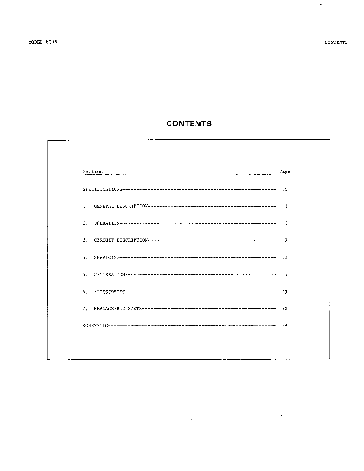
CONTENTS
Page 2
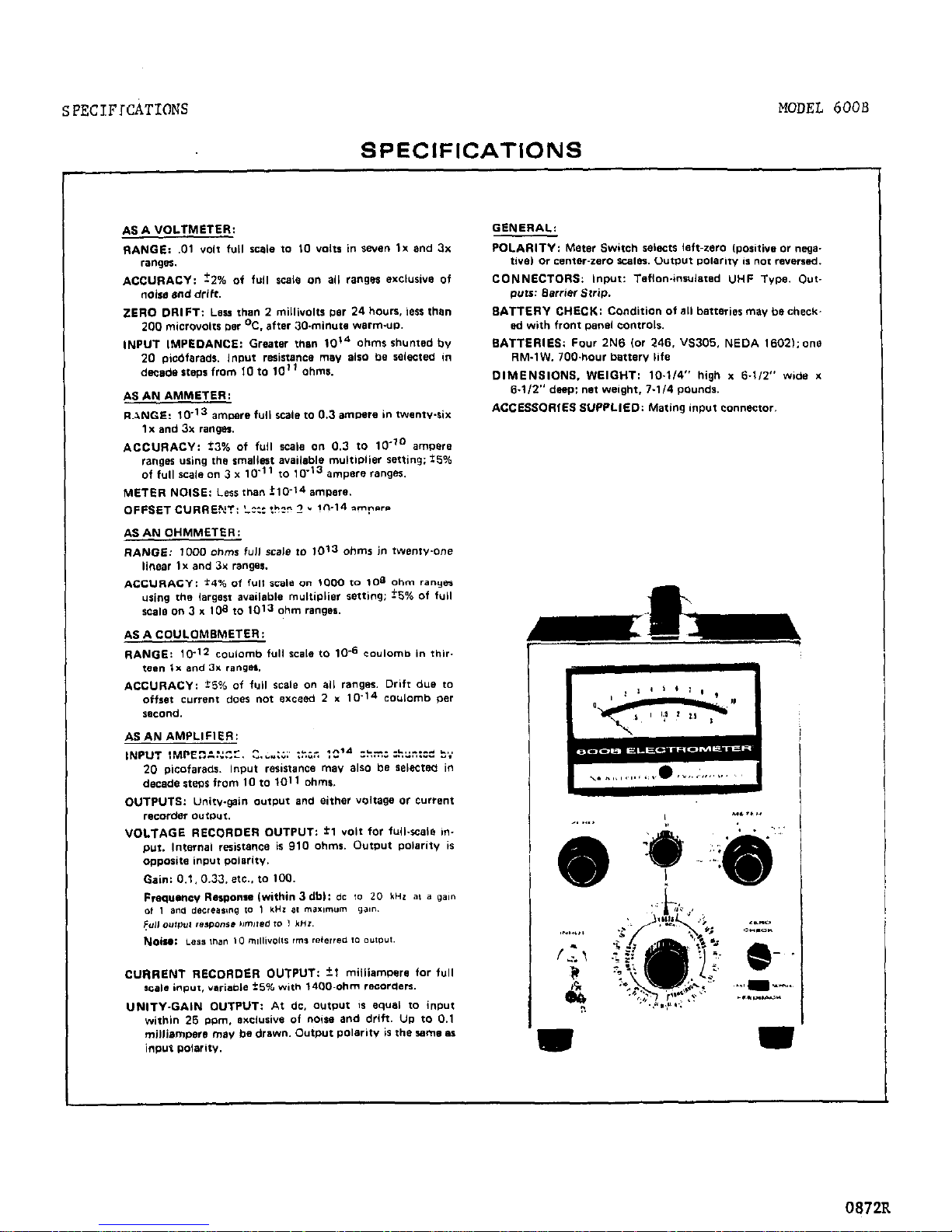
SPECIFICATIONS
MODEL 600B
SPECIFICATIONS
CONNECTORS: Input: Teflon4nrulared UHF Type. Out-
puo: &wrier srrip.
BATTERIES: Four 2N6 (or 246. VS305. NEDA 1602,; one
RM.IW. 700waur lxmerv life
DIMENSIONS. WEIGHT: 10~1/4” high x S-112” wide x
6-l/2” deep: net weight. 7.114 poundo.
ACCESSORIES SUPPLIED: Mating input connector.
7
0872R
Page 3
MODEL 6008 ELECTROMETER
SECTION 1.
GENERAL DESCRIPTION
GENERAL DESCRIPTION
uremenfs with a minimum of adjustment. Zero drift with
rime is less than 2 m” per day.
zero offset due to
temperature change is less than 200 microwits per %.
after a ,O-minute warm-up. This offset, however. can
easily be compensated for with the front-panel zero
controls.
b.
fast wnrm UD is an inherent characteristic ok
this Electrometer. It can be used well wiehin 30
minutes of a cold scare on the mose sensitive range
and nlmosc immediately on less sensitive ranges.
d.
‘the ,“O-hour life ai rhe batteries enables us-
age in long-term experiments xiehauc interruptions
<or replacement. Baeeery life is maintained even wiwn
the i-milliampere recorder output is used. Fur rilrther convenience. battery condition is readily check-
ed on the panel meter.
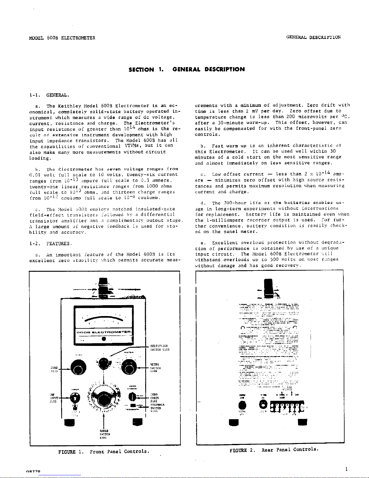
1
FIGURE 1.
Fro”,. Panel cantro13.
Page 4
GENERA‘ DESCRIPTION
MODEL 6008
TABLE l-l.
Front Panel Canerols
Functional oescripeian
Paraeraph
Sets the paramet~~r to be measured:
VOLTS, AMPERES,
?&S or COULOMBS.
2-2
MULTIPLIER Switch
(SlOS)
sees rix? full-scale meter sensitivity.
When used with AMPERES, OHMS or COULOMBS
the setting should be multiplied by ehe
RANGE setring.
2-2
METER Switch
(5106)
Controls parer co instrument. Also selects
the meter polarity and center scale.
2-2
ZERO Control
FINE (R133)
2-2
ZERO CHECK Switch
(5102)
FEEDBACK SWFtCh
(5103)
INPUT(.JlOZ)
2-2
2-2
2-2
TABLE 1-2.
Rear Panel Controls and Terminals
ZERO Control
COARSE (slo::
lV-lMA CAl Canerol
(R179)
Adjusement for recorder output.
2-7
Barrier strip cunnecrion (J104)
Xl
Unity gain output.
2-S
OHMS GUARD
output low Con".?cflo*.
2-7
A Connect link to OHMS GUARD when using 1V o"QmF.
2-7
B
Output high connection.
2-7
GND Chassis ground (input low).
2-7
Page 5
MODEL 6000 ELECTROMETER
OPEKATION
SWTION 2.
OPERATION
2-1.
INPUT CONNECTIONS. The Model 6008 INPUT Recep-
cacle is a Teflon-insulated UHF connector. A shield
cap is provided. The ground posr, below ehe Recep-
tacle, is conneceed co chassis ground.
a. The accessories described in Sectton 5 are designed co increase rhe accuracy and convenience of
input connecfions. Use them eo gain rhe maximum c=pability of rhe Model 6008.
c. Use hixh resisronce. low-loss marerials - such
as ‘Teflon , recommended,, polpe~hylene or oolpsqrene
- for insulation. Insuinci”” leakage resiseance of
test fixtures and Leads shouid be several orders of
magnitude higher than rhe internal resistance of the
SOUrCe.
Excessive Leakage reduces the accuracy “i
reading irom nigh imoedance sources.
coaxi cabies
used should be II io” noise type whici, employ a graph-
ite or ocher conducrive coacinq berrreen the dieiectric
.Ind ehe surrounding shield or=id, An+2nol-Sorg Elec-
tronics core., ?,icr”do~, I:::. , _..” “_...r.-.. ..LL5 aLIu
lz-lble co. make socisixcory types.
NOTE
Clean, dry connecrions and cables are very imporcaoc to maincain the value oi 311 insularion
materials.
Even the besr insulation will be com-
promised by d”SC. cirrc. so,oer Tl”X, LilrnS of
oil or water vapor. A good cleaning agent is
methyl =lcohoi. which disolves most common dirr
wirhour chemic=lly acr=cking the insulation.
:,ir dry the cables or ~onnecei”“s after uashing
vith alcohoi or “se dry nirrogen if available.
Or, if available, Freon is an excellent cleaning
agent.
d. When working with a high impedance source any
change in shunt cnpaci~once of the input circuit will
cnuse disturbances in the reading.
Nake the messuring
sefup as rigid as possible, nnd eie down connecting
cables to prevent their ,!?A~iL%iii.. ;\ i~il.illY”Ub “LYLA-
tion may appear 8~ the outpur as a sinusoidal signnl,
=nd orher precaurions may Le necessary co isolace rhe,
insrrumenc and connecting cnble from the “ibra+zton.
e. For low impedsnce meesuremencs - below LOS
ohms or above LO-8 ampere - unshielded leads may be
used and a binding post adapeer may be used. however,
keep the leads short.
f. When the Model 6008 is used on the most sensi-
tive current range with the FEEDBACK Switch =e FAST,
Borne insulators
- 4uch as Teflon - may produce random signals which show up as erratic meter deflections.
InsulaCion used in the Model 6008 is carefully seiec-
ted LO minimize these spurious signals.
g. If a well shielded chamber and a well made high
impedance transfer switch is
available
it
is advantage-
ous CO connect ehe Model 6008 to the circuit only when
a reading is being made.
In ~“me cases, rhe offsee
current can charge the external CASE circuifry. ilne
e::ample of this occurs when measuring a capacitor’5
leakage resistance by observing the decay of the ter-
minal voltage. If rhe leakage c~rre”:~is less than
the offset current (Less thnn 2 :< LO-
smoere, there
may be no decoy of the terminal voltage when ehe Elrc-
trometer is left connected across the copacicor’s fer-
“i”8iS.
XOTE
Keep the shield cao on the INPUT aeceofocle
when the ~leccromerer is nof in use.
3-2.
PRELMINARY PROCEDURES.
8. Check battery condition by holding the llETER
Swirch tn the S,,TTER,’ CHECK position. Turn the ilul-
ciplier Switch eo 10, 3 end I pOsitiOns =nd observe
one meter readings. The meter shoutd read one-haii
of fllll ‘.-.!e or more in ench Nuleiplier switch ?“Si
tion.
Table f.
show the batferies checked by each
POSiCi”“. Ii rhe reading for any baccery is below
one-i,alf full scale, replace the indicated baetery.
TABLE 4.
Nultiolier Switch Positions far Checking Conditions
of SatCaries.
SaeCeev Checked
10 BA103 di DA104
3
SAlOl 6. k4102
1 Ml05
b. Set the controls as follows:
ZERO CHECK nutcon
Range Swirch
EUICI~L~~~ Switch
FEEDBACK Switch
METER Switch
LOCK
VOLTS
1
NORMAL
POWER OFF.
.c.
Turn the METER Switch to CENTER ZERO. Within
ten seconds, ehe meter needle should come co the ce”-
0872R
3
Page 6
OPERATION
HODEL 6OOS ELECTROMETER
ter zero pasit.ion.
1f not. adjust the meter zero
with the front panel ZERO Control. Normally, there
is no need co “se the COARSE ZERO Switch.
Range Switch to lo-’ AMPERES range.
Set the full-
scale voltage range with the ~“lci~lier Switch. Operaeing procedures are the same as subparagraph b
above.
d. After a
few moments increase
the voltage sensitivity by advancing the Multiplier Switch to .3, .1,
etc.
Continue zeroing with the ZERO Control.
e. After long periods of starage or after an over-
load, the Model 6008 nay drift excessively. The in-
put cransistars are insensitive to mechantcal shock;
however. B severe inpa overload may cause a zero
offset. This is corrected with the Zero Controls.
Drifting, though. can occur foe several hours.
f.
Although the offset current of the Electrom-
eter is much below that found in conventianal valt-
meters. it can be observed on the meter.
The c”rrent
charges ehe input caoacitance. and the Electrometer
appears to drift uhen the input is open.
Use the
ZERO CHECK S”tr~n co discharge the charge build-up.
Depressing the ZERO CHECK Button removes all signal
from the amolifier.
2-3.
“OLTXE \E‘\SUREEENTS.
a. The liodel 6~3011’s high input impedance allaws
circuit measurements wi’chaut causing circuit loading.
FOC law resistance in-circuit tests, the input resis-
tance can be lowerr<, 1,, -v,..:,.: ,,:, ‘k-t&p ~,i~c,b:,e,,is.
Make all voltage meas”rement~ with the FEED-
BACK Switch & in the NORMAL posieion.
b. High Impedance Eleasurements ( LO14 ohms, ‘0
picofarads), Follow the instr”ctions of paragraph
2-2.
Set the concrois as foliows:
ZERO CHECK Sutton
LOCK
Range Switch VOLTS
multiplier Switch
LO
FEEDBACK Switch
NORMAL
METER Switch
CENTER ZERO
connece the ““know” source co the INPUT Recepeacle
and unlock the ZERO CHECK Buteon. Set the METER
Switch to + or -, as necessary. Increase the sensi-
tivity with the Multiplier Switch. Recheck the zero
setting after increasing the sensitivity.
Low Impedance Measurements. TO decrease the
in;& resistance frnm
1OL4
nh”w +Pe *II,- nnn.y CWifCh
to one of the AMPERES ranges. The input resistance
is now the reciprocal of the current range. For instance, to obtain an inpur resistance of 10’ ohms -
which is normal for convantional “T”Ms - set the
d. To measure ~~“rces more than 10 volts, “se the
Model 6102A 1O:l Divider Probe or the 6103.4 1OOO:l
Divider Probe.
The Model 6102A extends the Model
6OOB’s
range to 100 volts; averall accuracy is *&%
and Input resistance is 1010 ohms.
The Node1 6103
extends the Model 6008’s range to 10 kilovolts’ overall accuracy is r6% and input resistance is 10
12
ohms,
Follow the same Operating procedures with the dividers as in subparagraph b. The riall-scale voltage
range is the divider ratio times the MultipLier Switch
setting.
2-4.
CURRENT MEASUREMENTS.
a. The Model 6008 can measure currents three ways.
1. In the normal method - used on any range -
the current is determined by measuring the voltage
drop across a resistor shunring che’amplifier in-
put. This method is useful when lower noise is more
important than faster response speeds or if some
damping is needed.
2. In the fasr method - far “se anly below the
10-Z ampere range - the shunt resistor is between.
the amplifier ““ep”t and input in the feedback loop.
This circuit largely neutralizes the effect af inpue capaciey and greatly increases the response
speed. Also, the inpue voltage drop is reduced to
less than One millivolt on any range.
3. For galvanometric current measurements, the
Model 6006 acts as B null indicator between a very
cccurate current source and the “nknawn current
SO”CCe.
b. Rise time varies primarily with the current
range, the input capacity and the method used. With
ehe FEEDBACK Switch in ehe FAST oosition. the rise
time on ehe ?ast sensitive range is less than 2.5
seconds and on the lo-6 ampere range is less than 3
milliseconds. Given a choice. it is beteer ta place
the Electrometer near to the current source than to
the data reading instrument. Transmitting the input
signal through long caaxial cables slightly decreases
the respanse speed and significantly increases noise
due to the cable capacitance.
c. Normal Methad (0.3 to lo-l3 ampere ranges)
1. hollow rhe instructions
of
paragraph 2-2
Set the controls as follows:
ZERO CHECK Sutton
Range Switch
Multiplier Switch
FEEDBACK Switch
METER Switch
LOCK
10-l AMPERES
1
NORMAL
CENTER ZERO.
Connece the unknown source to ehe INPUT Receptacle
and unlock the ZERO CHECK Sutton. Set the METER
Switch to + or -, as necessary. Increase the sen-
4
0872B
Page 7
MODEL 6000 ELECTROMETER OPERATION
FIGURE 4.
Error Due to hmeter Reeisfmce.
Current SOUPCSS may be considered a voltage (E) in series with 3
resistance (a).
the current with the ammeter short circuited is I = E/R.
!4ith the short circuit removed, the
effective ineue resisrance of the ammeter (Ri”) is in series with the source resistance (R). The current in
the complete circuit is reduced and Imere= =
E/(R i Ri”). If the effective srmneter input resistance is small
camparea to 2. :,,ter ,., I a”d the error introduced by circuir loading is negligible.
sensicivic:: k.ith the d.inge sw~cch and the Wiclpiier
Svitcn.
31, not set c.i:e !luitiplier jwiwh higher
than 3 for Lange Switch settings LO-3 and above.
Check zero xieh the ZERO CHECK Sutton.
1.
The rull-scale curre”c range is the Range
Switch setting times ~i:e !iulriplier Switch setting.
use the smallese >lulti=lier Switch setting possible
to obeain the best accuracy.
The input resistor
varies with the Range Switch setting. from 10 ohms
at 10-l .u!PERES CO iUi! ohms for lo-11 AHPERES.
The input voltage drop is the Meyer reading times
the Multiplier Switch serFin!.
::mT.
On the iaw current ranges, baiance out ihe
oifset current vitb the Zero Controls or
suberacr ehe value from the reading. To
find the amount of offset current, cap the
INPUT Receptacle and read the meter.
d. Fast
Eleehod (ranges
below 10-j ampere).
1.
Fallow the inseructions of paragraph Z-1.
see the conerois as follows:
ZERO CHECK Sutton
Range Switch
,Hultiplier Switch
FEEDBACK Switch
METER Switch
LOCK
lo-” AXPERES
1
FAST
CENTER ZERO.
Connect the unknown source to the
INPUT
Receptacle
and ““lock the ZE:.’ ?LF.Y p:,?+-- =.- tL* ‘!--‘”
Switch to t or -, as necessary.
increase the se”sitivity with chc I;ar,ge Sw,,ci~ a”- ~lir kurLIpiier
Switch.
DO not set the Range Switch to 1O-5 AHP-
ERRS or higher.
Check zero with the ZERO
CHECK
Button.
Da nor short the input because this will
remove the
feedback
from the circuit.
“LlhSR
2.
The full-scale current range is the Range
Switch setting times the ~lultiplier jwirch secti”g.
When selecting ehe ?luleiplier Switch setting, re-
member mail seer,ings permit lwer currene 'iour'ce
resistance. 2nd Larger settings improve insceumene
zero seabiliev.
3. !$ich the fast method, the input drop is re-
duced and the response speed is
increased
at ieasc
100 times. iiowever,
follow rhese cautions:
a\ The internal impedance ai the unknown cur-
rent should not be less than .I ai the value oi
ihe Lardmck resistor wing "sea.
Otherwise,
~iir
full feedbacK voltage cannot be developed at the
input, and zero instability results.
The feedback
resistor value is the reciprocal of the AMPERES
range of the Range Switch.
b) The OHMS GUARD Terminal of the Barrier Strip
Cmnector is “a longer connected to case ground.
Therefore. do “at use a grounded recorder.
.is an
alternate. use the unity-gain output (paragraph
2-8).
C)
Use,‘with caution,
the fast mechod to meas-
ure capacitor leakages.
A very stable voltage
supply must
be used.
Connecting a capacitor fo
the inpue
changes the circuit to a differenciacor,
resulting in extreme sensitivity to very small
voltage transients and a” increase in meter noise.
e.
Galvanometric Method.
1.
Operate the Model 6008 as a picaammeter in
the tast method.
use an accurare reference current
source s,,ch as the Keithley Model 261 to buck out
the unknown current source.
connect as shown Fn
Figure 5.
5
Page 8
OPERATION
MODEL 6008 ELECTROMETER
2. Set the METER Switch to CENTER ZERO and “se
the higher current rangas. Adjust the buckout cur-
rent to indicate null on the Model 6006.
Increase
the Electrometer sensitivity as needed. When the
Node1 6008 is as close to null aa possible, the unknown current is equal to the algebraic sum of the
H.adel 261 setting and the Model 6008 current read-
ine
Method. Cse an Llccur3te reference currene source CO
buck 0”~ ehe unknown c”rrenf s~“rce. The Eladel 6008,
on its current ranges. ierves as a null detector.
“se a UHF-tee ittlng at the Xodel 6008 input,
connect the Elecz:Jmeter to the two s~“rces with CO.%ial cable. Select cable carefully for very low currents (see parngrapil ‘-1).
2-5.
KLSISTANCE XEASUFGXZNTS.
II.
The Xodel 6000 can meas”re resistance by tw
merhads.
1. In the constant current methad, the Electrometer measures the voltage drop across the unknown
sample as a knno;.r.,
_^__._...
_“...,-..... i..Zi’i;lCi L:u”,r &‘“ugiL
it.
The voltage drop is proportional to the resis-
tance Of the snmple.
In this method the Model 6008
can be used in one af ~0 different modes: normal
or fast.
a) The normal wj:r is trcommended for “se from
1 kilohm to 1011 ohms.
b) Above lOi
ohms the fast method is preferred. It results in faster respanse speed and
also nullifies leakage across the Electrometer
input, since the pacential acr‘oss the input ter-
minal is small.
2.
In the preceding merhod, the voltage across
the sample cannot be arbritrarily see. I” some
cases. as in measuring capacieor leakage, this results in excessively long testing time.
In the
voltmeter-anrmerer method the Moiri COGa is “sad as
a picoammeter. The unknown resistance sample is
connected to an external known voltaee 80”rce and
ehe current through the sample is measured.
Either the normal or fast method may be used. The resistance is calculated from the readings.
NOTE
Discharge any capacitor completely befare
removing it from the circuit.
Depressing
the ZERO CHECK Sutton shorts the input
through a IO-megohm resistor, providing a
discharge path.
b. Xormal constant Current Method (recommended f,ar
“se from 1 kilahm to 1011 ohms).
1. Set the controls as follows:
ZERO CHECK Butfo”
Range Switch
Multiplier Switch
FEEDBACK Switch
XZTER Switch
LOCK
1011 OHMS
1
NORMAL
Unlock the ZERO CHECK Button.
Check zero only wit!:
the ZERO CHECK Button.
NOTE
Do not open circuit the Electrameter 0” the
OHMS ranges; the input will develao “o f~
10 volts due to its consrant current characteristic. Keep the input shorted or the
ZERO CHECK Sutfon Locked.
2. The full-scale ohms range is the Hultiplier
Switch setting times the Range Switch setting.
II s c
the smallest Range Switch se:cing possible to obtain the best accuracy.
3. Before making a final :eading, manipulate ti:e
X~ltiplier and Range Switches. so the sample is
tested at a number of test potentials.
The applier.
test voltage is the percentage ai full scale that
the meter reads times the-X”iti?lier Switch seccin;.
4. When the test current is applied, the high
terminal of the INPUT Receptacle is positive.
The
test current is the reciprocal of the OHMS Range
setting.
NOTE
Shield the inpue if the resistance sample
exceeds lOa ohms.
c. Fast Canstant C”rrent(C”ardedi Method (recom-
mended for “se from 1011 to 1013 ohms).
1. Follow the instructions of paragraph 2-2
set the controls as fallows:
ZERO CHECK Button LOCK
Range Switch
1012 OHMS
Multiplier Switch
1
FEEDBACK Switch ?AST
METER Switch
c
Connect the high impedance side of the resistance
sample to the INPUT Receptacle and the low impedance
side t” the OHMS GUARD Terminal.
Unlock the ZERO
CHECK
Button.
Page 9
MODEL 6008 ELF.CTRO”ETER
OPERATION
2.
Read the resistance as in subparagraph b2
above.
d. voltmeter-amecer Method (to 1016 ohms).
1.
Turn
the ZERO CHECK Switch to LOCK. Connect
sample between INPUT receptacle and pawer supply.
(see Figure 6). Put a switch in the high voltage
line to ground low impedance end af the sample when
it is disconnected from the potential.
2.
Set the FEEDBACK Switch to NORHAL.
lJeilallp
this method is best, since inStabilities can arise
for resistance samples less than 0.1 the value of
the feedback resistor.
3. TO make e meaetiremenc. scare with switch S
3s shown in Figure 6 and make sure the ZERO CHECK
Sutton is set to LOCK. set switch S to apply e pa-
tential t~cross the samoie far a known period of
rime. ~!:en uniock rhe ZERO CHECK Gutcon and take
the reading.
$9~ eke !<a,ge Switch ea 10-l A:NPE?.ES
and increase sensitivity until .I reading is obtained.
U.
I!: the ?oce”ri;il mp1ieu is less than 100
rimes the inmr droo. the resistance is equal to
rhe difference between the aoplied potential and
the input drop, 211 :I,, -~’ ‘,., ,.a ..,.,. :
FICUIW b.
:!easuring ~es~srnnce oy tne VoLcmecer-
,‘mmecer Xethod.
;s:>:::;; rrc:: : I::.:::: “I:‘--? “,
is applied to the unknown resistance sample, I<,. The
Xodel 6008
measures
the current through R,. from
wi,ich the resistance is calculated.
Switch S connects
the low end of R, ea ground when na potential is
appiied.
7.
If the current is read by the face method,
the input drop Is so slight that it need not be in-
cluded in the calculation.
If the capacity shunted
acreee the sample is large, such as encountered in
capacitor leakage measurements. the faster methad
increases response speed and thFs cannectian is recannended. Xate. however. Lhat power supply transiente will be magnified.
2-6. CHARGE KSASUREMENTS
a. Follaw ehe instructiww of paragraph 2-2. see
the controls as follows:
ZERO CHECK Button
Range Switch
>lultFolier Switch
FEEDBACK sviech
XETER Switch
LOCK
10-7 CO”LOPBS
.Ol
FAST
CENTER ZERO
b.
For recording with the Node1 6008, use the
Xeiehley ?lodel 370 Recorder for ease. economy, versa-
eility and performance. The Model 370 is a pen recorder with LO chart speeds and 1% linearity. Interface pnblems ofren encountered between a measuring
inscrumenc and a recorder ore avoided using the Node1
~> 7n
\‘- preempiifier is needed.
:;0 special wiring
is required. when using the Node1 370 make sure the
Recorder’s sensitivity conrrol is set t0 maximum
(completely clackwise).
oR72R
7
Page 10

OPERATION
WARNING
The Model 6008 may be used with the FEEDBACK
Switch in FAST position with other instrumerits.
However, make sure that the OHMS GUARD
terminal (output lo”) is floating with respect
to chassis ground.
c.
I-Volt
output.
Place the shorting link between
the OHMS GUARD Terminal and Terminal A.
connect os-
cilloecopes and pen recorder amplifiers to the OHMS
GUARD
Terminal and Terminal S on the barrier strip
EO”*W.TtOC.
Adjust the lv - LMA CAL Control for fullscale recorder deflection to correspond with fullscale meter deflection. Output is *l volt.
Inter-
nal resistance is 1000 ohms.
The METER Switch does not reverse the output polarity
Output polarity is opposite input polarity.
FIGURE 7.
Divider Clrc”its Acrosr Modri hnna “wv”“’
for Driving 50 and LUU-millivolt Recorders.
use 5%
resisrors in rhe dividers. The value of resistor R
is one ohm far every 1mV of output.
MODEL 6008 ELECTROMETER
d. l-Milliampere Output: Connect l-milliampere
instruments to the OHMS GUARD Terminal and Terminal
B on the Barrier Strip Connector and remove the shart-
ing link. The output is approximately 1 milliampere
for full-scale meter deflection on any range.
Fo=
exact output, adjust the meter on the .Ol volt range
with the ZERO Control for full-scale deflection.
The”
adjust the 1V - 1MA CAL Control until the recorder
reads full scale.
Check the recorder and meter zero
and repeat adjustment if necessary.
e.
For servo rebalance recorders, use a divider of
approximately 1000 ohms total es show” in Figure 7.
I” this application the
shorting
link between OHMS
G’JARD and terminal ‘A” should be disconnected. The
value of the divider resistor should be one ohm for
every 1 m” OUtput.
f. When the FEEDBACK Switch is in the NORMAL pasi-
elan, the GUARD terminal
of the Rarrier Strip Con-
nector is connected to the instrument case.
merefore. no difficulty will be experienced using oscilloscopes and recorders with the Node1 6008 set for
normal operation.
In FAST position. however, Che
OHMS GUARD terminal is floating with respect to
chassis ground. Therefore the recordine instrumenr
must be capable of floating such es witi rhe Keithley
Model 370 Recorder,
2-S.
UNITY
GAIN OUTPUT. The unity-gain amplifier
can be used as a” impedance matching device to minimize circuit loading errors
a.
The unity-gain output is equal to the input
wi,thin 7.5 ppm when the load reeietance is 100 kilohms
or greater. By placing the Model 6008 between a IOn
ohm source,
For example, and J. 0.01% voltmeter with 1
i-megohm input resisrance, overall accuracy better
the” 0.025% ce” be achieved.
I
FIGURE 8. bleanuring Pore”l~?l -6 !J?$ !.:---:I:.:.. c----L “I.;. ;.c;;i. Accuracy.
a high-resistance source.
The Model 6008 is used between
V,, and e 0.01% voltmeter to obtain high accuracy without causing circuit loading.
Page 11

MODEL 6008 ELECTROMETER
OPS~TION, CIRCUIT DESCRIPTION
1. Connece the voltmeter co ehe xl and OHMS
GUARD Terminals as shown in Figure 8. The OHMS
GUARD Terminal is at ground with the FEEDBACK Switch
in NORMAL. laxnwm output amplitude is 10 volts
peak-to-peak?
2.
Adjust the Model 6008 zero Controls co obtain
a zero-voltage reading on rhe exrernal voltmeter.
Make cure the latter’s sensitivity is high enough
far a precise zero adjustment.
b. When the FEEDBACK Switch is in FAST position,
the unity-gain terminals permit more convenient con-
nections to oscilloscopes with a load resistance of
greeter than 100 kilohms without special precautions.
In this mode, the Xl Terminal is grounded and ehe
OHMS GUARD Terminal delivers en output equal co the
input signel.
SECTION 3.
CIRCUIT DESCRIPTION
3-l. CESEUL.
a. The Keirhley Yodel bOOR is basically an eutreme-
ly stable and iinear dc ~volcmeter with a fuil-scale
sensitivity oi 10 millivoits and an input impedance of
10L4
ohms shunted by 20 ?icoiarads.
By using the frone
p.nel controls, shunt m~istors and capacitors are se-
lected to make meesuremencs over a total ot 61 YOLC-
age, currene, fes~scance: .2nA *nl*lnmh -1”Z-E
r?~~~,mt
and resiseance dre measured using precision resistance
stanaards, irom 10 ohm wirewound resistors to 1011 ohm
glass sealed, deposited carbon resistors. coulombs
are measured using close tolerance polystyrene film
capacitor standards.
b. Batteries furnish the neceesarv amolifier oower.
3-2.
“OLTHETER OPERATI(IN.
a. The Model 6008 empioys matched insulated-gare,
field-effect transistors fallowed by a eransisror differential amplifier with a high-voltage comvlementary
oueput stage. Figure 9 shows the block diagram for
the voltmeter made of operation.
b. Voltmeter operation of the Model 6008 is as
fallows:
1.
The amplifier is always in a unity-gain, input
voltage co output current converter contigurarxm.
The internal circuitry is arranged such that a full
scale input voltage (ei) results in exactly a 1 milliampere outout curreoc through the divider string
composed
of
Rm. R177, end the meter. Voltage gain
of the circuit is determined by the ratio of R177 to
h.
Output is taken across R177.
2. The voleage drop across the amplifier is
where & is the amplifier loop gain, greater t!lan
5 I 10’ on all ranges.
c. ‘ihe complementary oufpot sK.ege, 4109 and 4110,
drives the amplifier ground at the same potential as
ehe input signal. ‘Thus the input impedance is maintained for any value input voltage and the need for
input dividers is eliminated. ‘The amplifier *round
is not chassis ground, hue it is connected directly
to the unity gain output.
NOTE
Refer to Schematic Diagram 22BOSE for circuit designations.
3-3. “OLTELETER CIRCUIT.
a. The amplifier input staSe is a pair of insulated
gate,
field-effect transiecars, Qlll and Qll5, in a
differential configuration.
The gate of Qlll is re-
turned to amplifier common, the unity gain output.
b. Depressing the ZERO CHECK Sutton, S102, places
the gate of the active insulated gate devices at zero
p”LSLLLldl.
c. The input stage is fallowed by a transistor differential amplifier. composed of QlOlA-QlOS. Q106 and
Q107 make up the output gain stage, which is utilized
in e gain multiplier configureciao. This stage provides the remainder of the high gain required by the
r%“L”D
9
Page 12
CIRCUIT DESCRIZ’TION
MODEL 6008 ELECTROMETER
UHF INPUT
>i
amplifier.
ALSO, this stage prevents fold-over and
lock-up with ?ositi”e input overloads.
OiOdR DlO1,
beeween base and emitter of QIOB, prevents fold-over
and lack-up under negative inpue overloads.
d.
frequency compensation networks provide a I-W-
trolled frequency characteristic to insuee stability
under all conditions ai caps:iLivr iuading on input
and o”ep”t while an any =ange.
e. ‘rhe recorder o”cp”c is derived from the c”==ent
flow from 4109 and QllO through the divider, Km, R177,
and the mete=. With the shorting link between the
OHMS GIRD Tenninal and Terminal h (paragraph 2-7~)
21 vale fo= full scale deflection is obtained a= the
mtpuf by ~1.1 milliamperes flawing through the divider.
3-4. AMMETER OPERATION.
a. Normal Method. In the normal method of c”==enC
measurements (FEEDBACK Switch in NORMAL position),
one of the Range Switch resistors, R136 through R146,
shunts the input.
(See Figure 10). The Model 6008
then meas”=es the voltage drop acrbss the resistor.
The meter is calibraird io ‘ea..i i&e ~“arni in ampexs
for the appropriate range.
b. Fast Method.
In the fast method of c”==ent mea-
S”=aments (FEEDBACK Switch in FAST position), the MO-
de1 6008 functions 88 an attnwEe= with negative feedback. The differenelal amplifier output is divided
by the Multiplter Switch resistors, R168 to R174, and
fed back to the am<lifier inp”t through a feedback
resistor seleceed with the Range Switch.
(See Figure
10).
~loaring ground is connected to the law imped-
ance side of the input, and the output ground is
flOaCi”g.
~hls method increases the response speed
by minimizing the effects of inp”t capacity; it also
reduces the input drop to less than 1 millivolt.
3-5.
OHMMETER OPERATION.
a. No=mal Nerhod. I,, the normal method of r‘esis-
eance meas”=emenEs (FEEDBACK Switch in NORMAL posi-
eionj,
the Model 6008 uses a constant-c”==ent, voltage.
drop ci=c”It. Refer to Figure 11. Rx is the unknown
resistor. A voltage source, E, applies a potenfial
acroes Rx.
The source is obtained f=om the batteries
through the resisrar divider nerwork, R128 through
R130.
E varies depending upon ehe OHMS range used.
The voltage source is connected beeween floating
ground and the input gaee of Q115 through R,, the
range resistor. !+ is one of the resistors, R136
through R146. I is equal to E/R., =egardless of the
value of R,, as long as the voltage drop across Rx
does not exceed the Multiplier switch setting. This
circuit provides a t=“e source regardless of the in-
put.
The Model 6008 can then meas”=e the voltage drop
across R~ and indicate ehe =esisfance value on its
;zlib=n:ed mete=.
L
-.*-“4 Method.
_____-
1x1 the guarded method af =esis-
tance meas”=emen=s (FEEDSACK Switch.i” FAST position
and the sample resistsnce connected between the INPUT
~erroinal, 5102, and the GUARD Terminal), feedback is
applied through the sample. Refer tO Fig”=e 11. The
circuit is similar to the normal method, except far
10
0872rl
Page 13
MODEL 6008
CIRCUIT DESCRIPTION
the feedback. This reduces the slowing effect of the
3-6.
COULOMBMETER OPERATION. The Model 6008 circuit
instrument’s input capacity.
Leakage error is also
far measuring charge is similar to that used for an
reduced since the potential ac.ro~~ the INPW Terminal
ameter with the fast method. A negative feedback is
is small. In this mode. floating ground is connected
applied around a shunt capacitor, cl10 to ~113, se-
Co the low impedance side of the input and the output
lected with the Range Switch. The shunt capacitor re-
ground is floating.
The GUARD Terminal is at output
places Rs in Figure 10.
The stored charge is propor-
ground potential.
tional to the voltage across the capacitor, which is
measured by the Model 6008 voltmeter circuits.
FIGURE 10.
Slack Diagram of Fast Mode Picoamecer.
Page 14
SERVICING
MODEL 6008 ELECTROMETER
SECTION 4.
4-1.
GENEPAL.
section 4
contains the maintenance and
troubleshooting procedures for the Model 6008 Electrom-
eter. Follow these procedures as closely es possible
to maintain the performance of the instrument.
4-2.
SERVICING SCHEDULE.
Periodically check the condition of the batteries, using the convenie::t battery
check as described in paragraph 2-i. Exceot Ear baetery replacement, the Model 6008 requires no periodic
maintenance beyond the normal care required of high-
quality electronic equipment. The value of the high-
megohm resistors, Rl44, R145 and R146 should be checked
approximately every 6 months for specified accuracy.
4-3.
PARTS KKPUCEMENT .
a. The Keplaceable Parts List in Section 7 describes the elecrricoi comoonents of the Elecrrometer.
Replace components only 8s necessary. Use only reliable replacements which ma-r rh- 4ycifications.
b. The XOS FET input c-i-=i?rnr=, Qll5 and ‘>lll,
are specislly selected nod matched; order only as a
plug-in
unit, part number 23735
, from Keithley In-
strnmenes, 1°C.
4-4. TRO”BLESHOOTING.
8. The procedures which follow give instructions
SERVICING
for repairing troubles which might occur in the Model
6008.
Use the procedures outlined and use only spec-
ified replacement perts.
Table 5 lists equipment rec-
ommended for troubleshooting.
If the trouble cannot
be readily located or repaired, coneect Keithley Instrumenes, Inc.,
or its representatives.
b. Table 6 contains the more common troubles which
might occur. If the repairs indicated in the table
do not clear up the trouble, find the difficulty
through a circuit-by-circuit check such as given in
paragraph 4-5. Refer to the circuit description in
Section 3 to find the more critical components and to
determine their function in the circuit. The complete
circuit schematic, 22808E, is in Section 7.
a.
If the instrument will not operate, check the
condition of the batteries (paragraph 2-2). Then make
sure the shorting link is connected between the UIIMS
GUARD and A Terminals on the Barrier Strip Connector.
b.
The schematic diagram indicates all transistor
terminal voltages referenced to either iloacing ground
or output ground: e properly operating Electrometer
will have these values -lo%, if operating from fresh
TABLE 5.
EO
uipment Recommended for xodel 6008 Calibration and Troubleshooting.
Use these instruments or their equivalenrs.
i”m.i,l!p*ili.
Refer co Paragraph
Keichley Instruments ::;z: :LJ zig;::; ‘;~::=;tor
5-4,5-11
Hewlett-Packard Modei 400 AC VTVM
5-12
Hewlett-Packard Xodel 3400A BMS Voltmeter
5-7
Keithley Instruments !lodel 153 Microvolt Anrmeter
4-5
Keithley Instruments Node1 241 Voltage Supply
5-6,5-11
Keithley Instruments !Lodel 260 Nanovolt Source
5-4,5-5,5-11
Keithley Instruments Xodel 261 Picoampere Source
5-11
KeLthley Instruments Node1 370 Recorder
5-9
Keithley Instruments Model 515 Megohm Bridge
5-10
Keithley Instruments Xodel 5155 High Megohm Resistance Standards
5-11
Keithley Instruments Model 662 Differential voltmeter
5-6
Tektronix Model 56lA Oacillorcone
5-11
Waveeek
Function Generator
5-12
1O:l end 1OO:l Dividers
5-12
12
a872R
Page 15

?,OOEL 6008 EmccROmTER
SERVICING
09698
13
Page 16

SECTION
5.
CALIBRATION
5-L.
CENERAI..
il.
me iunction a,i the C3libratio" Section is to
orovide a :nethad of checking the XZI
xiel 600" to make
;ure Ch"C ic cperalLes ?roperiy and within the speci-
:icarions given in 1clbla L '2" page ii.
once a year or when componenes are replaced.
,i
Check etle ?,lodel no09 accurac\ (paragraph 5-11)
once a year, after the other adjusments, or if impcuper operaeian is suspected.
5-2. C‘\LIBRATION SCHEDULE.
n.
check offset current (paragraph 5-8) 8f regular
intervals to make sure the input transistoes are functioning correctly.
b. Verify the value oi the high-megahm resistors
(paragraph 5-10) approximately every six months.
C. Calibrate the meter zero (paragraph 5-4) about
14
08728
Page 17
MODEL 600B ELECTROMETER
CALIBRATION
b. Check the meeer O-10 scale for no more ehan 1%
(l/Z division) tracking error going from zero to tull
scale in one-tenth oi full scale voltage steps.
a. Zero check the !,odel 6008 and set the inscrumenr
to the 10 volt range. Connect the Node1 241 Voltage
supply eo rhe Xodel 000~ ISPLT receptacle and to the
Yodel 662 oiifereneinl '!'aImeeer iligh teminal. Cannect the Electrometer 'I Terminal to the LOW rerminal
of ehe XodeL 662. set ehe ?,odeL 662 dial co 0 and the
Xuil Switch La ! aillivalt.
The Node, 662 shouid in-
clicnte al: or near zero.
SOTE
2. iepeac :.:e rese or iubparagraph 1 above usin*
-10 "OiCS.
j-7. YOISE CiECS.
Zero check the Electrometer and
connecr ehe OUTOUC ea a Hevierc-Packard XodeI 34OOA
ms "alemerer.
a. See the !ETER Switch co CENTER ZERO and zero
the Node1 6008 on the LO millivolt range.
b. *he oucpuc noise must be less than 10 millivolrs
rms an the 10 millivoit through 10 volt ranges.
5-8. OFFSET CURF\ENT CHECK. Check offset c"rrent
whenever excessive noise or drift is suspected. TO
read the offset current of the Model 6008, set the
front panel conero1s to:
Cap the INPUr Receptacle and unlock the ZERO CHECK
Burro”.
The offset current indicated on the meter
should be less than 2 x IO-l4 ampere.
(This is less
than 20% of full scale).
If this is exceeded, check
the battery condition and the input tran~i~eor, ~115.
If the insrrumene has not been used for a long rime,
allow it to run 7 hours before checking ehe offset
C"rT*"C.
5-9. DRIFT CHECK. The unit mutt be oii at !euse one
ihour prior ea a drift run.
a. see the front pvnei controls to:
ZERO C,iECK sutean
LOCK
Multiplier Switch
.Ol
Range Switch
'VOLTS
FEEDBACK Witch
SORMAl
NETER Switch
VOTE
If new lmtreries ihave been instailed, :he
Model 6OOB zero drift will be exceeded far
a? 1easr 24 ho"rS.
.\ge rhe unir isr 1'
hours co enable rhe barter? ccminni ,;o‘c-
ages to stabilize.
5-10. HIGH-bEGOHM RESISTOR "ERIFICWIOI
a. About every six months ie is necessary co check
the value of the high-megohm resistors, R144 to 13146
on the Range Switch. The instrument should be within
its rated accuracy far two or three years from the
time it leaves the factory. After Chis. some of the
resistors may drift sue of tolerance and should be,
_( .",
..:,. _..L.
?sdif high-megohm fe~i~for~ will affect
the accuracies of mea~uremenc~ far ehe 10T9 Co 10mll
HW'LKES and the 108 to 1012 OHMS ~eteing~ of the Lange
switch.
b. To check Cheae re~i~tora, it is necessary ro use
a bridge capable of better than 1% accuracy UP to 1O1l
0872B
15
Page 18
CALIBRATION MODEL 6008 ELECTROMETER
ohms such as the Keithleg Instr”ments Model 515 Xegohm
aridge.
1f such equipment is not available, two pro-
cedures are recomended to check out the resistors:
1.
Return rhe complete instrument to the factory
for resistor calibration.
2.
Replace the high-megahm resistors periodically
with a certiiied set from Keithley Instruments to
assure &moiute calibrntion accurncy.
a.
Checking tile accuracy is the q”ickest way to
spot f3ulty i’lodel 6OOB operation.
Perform the check
*bout once n ycac, if components are repiaced, or ii
tither adjustments ilre made.
If accuracy is verified
I)Yer sill ron~es, the Xodel 6008 should be nble to meet
311 spetific~ci,v~.s.
[I the accuracy must be checked
.,iten, check tijc stabiiif,v.
C. B: Connect the Xodel 6008 to the Xcdel
161 and monitor the oucpuc with the ?lodel 163 WM.
Check tl,c iull-acnle rrccurncy of all the c”rren~,posi-
tions on the I(an,~e Switch
ror the 10-o f” LO“’ :,>i-
PEP.? settings of the Range Switch, set the FEEDBACK
svitch to F;1ST .md the xultiplier Switch to 1.
‘The
jlodel 602 should indicacr GLS iIlrw. -~r‘;:lz : ~1. u,Y
iull scale to the 10ml” *m ere range; 15% of full scale
irom the 3 !i io-il to 10-
15
ampere ranges.
For the
ranges above IO-’ ,mpere, constr”ct B current sauce
WhoYe cl”tp”t is zo.25::. jet the Model 6008 FEEDBACK
svitck co SOprL4L 2nd the Yultiplier Switch to .O1 when
cniibracing these rnnges.
40TE
For 10-l mlpere t!lro”gil 10-5 ampere rnnges,
a Inrper ?hltipliec Switch setting will re-
sult in inaecurac~rs due co loading of the
current source: hence the .Ol Multiplier
Switch setting must be used. The appropriate current source is two decades less
than range setting; that is, on the 10-l
ampere range we IO-3 ampere source, etc.
d.
Resistance. Connect the high side of a Keithley
Model 5155 Resistor to the Electrometer TNPUI’ kecepLb-
cle and the low side to the OHMS GUARD Terminal. Check
full ,scale acrx~t.. : ?C
“.?I. +- yeib’.?“o nn ,h. I)il”$rp,
switch by measuring the voltage drop of the known cur-
rent across the known sample with the Model 6008. Test
current applied is the reciprocal of the OHMS Range
Stti”*.
Check the 103 through log ohm ranges for an
accueacy of +4% of full scale by using the resistance
meaa”rement method as described in paragraph 2-6b
(FEEDBACK Switch in NORMAL). Check the 3 x lo8 thro”gh
Id3
oh,,, ranges for on accuracy of t5% of full scale
by employing the resistance measurement method .os described in paragraph 2-6~ (FEEDBACK Switch in FAST).
e. Chaege.
To check the accuracy oi the Modei
6008 as a charge amplifier, set the FEEDBACK Switch to
FAST. Apply 10 volts from the Model 241 Voltage Supply through a Model 5155 10L1 ohm Standard to the Nodet 6008 input. Set the Multiplier and Range Switches
to the settings given in Table 8. Use a stop watch or
B Tektronix Model 561A Oscilloscope to time the rise
to full peek deflection. Check each setting to *5?..
TABLE 8.
Charge Ranges Accuracy Check. The Table gives the
xultiplier Switch setting, the Coulomb Range Switch
setting and the rise time for each coulomb range.
Rise ‘Time. %*=a
Range Switch
to Full Scnle
Setting, COULOMBS
5-12. FREQIIENCY RESPONSE C!LECK.
8. Zero check the unit.
Connect a Wavetek >iodeI
102 Function venerator through a iOU:l divider to the
!lodeI 600” input nnd connect the Electrometer output
to a Hewlett-Packard Model 400 AC VTW. Set the
Electrometer FEEDBACK Switch to NOR&U..
NOTE
If other than a constant amplitude signal
generator (wavetek) is used. it will be
necessary to monitor the o”tput ui the
signai generator with another VTVN in
order to maintain the same signal level
at various frequencies specified.
b. Zero the Model 6008 on the 10 millivolt range.
1.
set the signal ccneracor to 20 Hz at minimm
um.put.
Release the Electrometer LCRO CHECK autfon
and increase the Generator wfput to obtain 0.7 volt
cm nt the Model 6006 output.
2. Set the Generator to L kHz. The Electrometer
o”tp”t voltage m”st be within ~3 da of the 20 ,Lz
0.7 volt rms output.
c.
Zero the Model 6008 on the 3-volt range and
.:hange the divider to IO:i.
1.
Set the Generator to 100 Hz for minimum output.
Release me Electrometer ZERO CHECK Button and increase the ~eneeator o”tp”t to obtain .07 volt rum
at the Nodel 6008 output.
2. Set the venerator to 20 kHa. The Electrometer
output must be within t3 dB of the 100 HZ .07 vole
cm output.
08728
Page 19

MODEL 6008 &LECTROMETER
CALIBRATION
FIGORB 12.
ComponenE Layout of
Model 6008 Chassis. Front panel faces
left.
see Figure 13 far component layout
of X-189.
1069
17
Page 20

CALIBRATION
MODEL 6GOE ELECTROMETER
PIGIRE 13. component Layout for PC-189.
For other Model 6008
Components, see Figure 12.
1069
Page 21

MODEL 6008
ACCESSORIES
SECTION 6.
ACCESSORIES
6-1. GENERAL. The follawiq Keithley accessories
can be used with the Model 6008 to provide additional
convenience and versatility.
6-2.
OPERATING INSTRUCTIONS. A separate Instruction
Manual is supplied with each accassary giving complete
operating Fnformarian.
Model 6101A Shielded Probe
Oescriprion:
The Model 6lOW is a shielded cable with a needle-point
probe and 30 inches of low noise cable terminated by a
UHF connectar.
Model 61018 Shielded Probe
Description:
The Model 61018 is a shielded cable with a “gripping
I
type” probe and 30 inches oi low noise cable terminated
by a UHF co”nector.
\r
-..
Yodei 6103A Divider ?robe
Description:
The Nodei 6103A is a sbieided cable irirh a needle-point
pmbe and 30 incnes ai !O” n0is.e cable eerminaeed by a
LHF connector.
The orooe includes a iOOO:1 voltage
divider with a 101*2 input resistance. Accuracy is
+% at 30 kilovolts.
Hode1 6102.4 Divider Probe
19
Page 22
ACCESSORIES
MODEL 6008
Modbl 6106 Electrometer Connection Kit
Description:
The Model 6106 contains a group of the most useful
leeds and adapters for low cu==ent meeao=ement~. A11
eo,,,ponents are housed in B rugged carrying case with
i”di”idU.41 compartments.
Parts List:
oescription
Item
NO.
Keithley
Part No.
Cable, 30”, UHF to clips
1
19072C
Cable, 24”. UHF to UHF
2 la265c
connector, UHF to UHF
3 CS-5
Adaptor, UHP to BNC
4
cs-115
Adaptor, UHF to BNC
5
CS-172
Adaptor Tee, UHF to UHF
6
cs-171
Adapto=, Binding Post
7
190718
The two cables (Items 1 and 2) are coaxial shielded
leads useful for connections where low noise is essentie1.
The 24” cable (Item 2) ten be used to intercan-
nect two in~teument~ having UHF receptacles. The 30”
cable (Item 1) c8n be used to connect Co the circuit
under test through the use of clip leads. A binding
post adapter gives easy access to the elecerometer
“high” terminal. TWO unz fernal couplers (Item 3)
permit cables to be connected together. The UHF “tee”
connector simplifies galvanometric current meesu=ementE
when using a current source and electrometer or picoammeter. Adapters (Items 4 and 5) are useful fo= conversion from UHF to BNC terminations.
Models 2501, 2503 Static Detector Probes
Description:
The Models 2501 and 2503 are specially designed de-
tectors used to me.wure static charge on pla
Either probe mwt be used with an electrometer such as
the 6008.
Model 2501:
The 2501 is useful fur ,,,sorr.-r-..:A .Jf
.1---1 ^_ 119L
_ .._ _ b-
_..
surfaces.
The static heed is 3 inches in diameter.
Recommended spacing is 318” from the surface far
10,OOO:l divider ratio.
The 2501 is calFb=eted such
that a 1 volt deflection on the electrometer co==e-
spo,,ds
to 10 kilovolts of static charge.
Hodel 2403:
The 2503 consists of a rigid probe 112 inches m olameter.
Operation is similar to the use of the 2501
probe.
Model 6107 pH Electrode
Adepter
The Model 6107 is a test fixture which simplifies connections to the electrometer when making pH measuremerits.
The adapter c-n be wed wi.Ch elw.rrndes “an”-
faotured by Leeds & Northrup, Coleman and Beckman.
The 6107 can be used for guarded measu=ements BS shown
in the diagmm.
A voltage-to-pa conve=‘slo” chart 1s
supplied with the 6107.
---we
Xi
0877.R
Page 23

MODEL 6008
ACCESSORIES
the Model 6104 is
or three-terminal
teflon insulated.
Model 6104 Test Shield
57
JS
“1
56
EXT
TO 6008 GUARD
INPUT
HIGH O-+-C BNC
32
Jl
GND
53
Appiicaeians:
CASE
34
J5
1. Two Terminal Connections. nrsisww. IW**U~*mencs can be made conveniently using the INPUT and
GROUND terminals on the Test BOX. Connect the eiec-
tromecec eo the SNC output.
Use the electrometer in
NORI.,@.,. mode for ohms measurement.
2.
Three Terminal Connecfions. The GUARD o"fput
on the Model 6008 electrometer can be used for resistance measuremenes where the effects of cable capac-
ieance may be significant.
~m,necc the unknown between
INPUT and EXT terminals.
Connect ehe EXT terminal to
the WARD output on ehe eiecteometer.
"se the elec-
erometer in FAST mode ior ohms measurement.
Description:
The ModeL 6105 is a guarded test fixture far meQsu=ement of surface and volume resistivieies.
The chamber
is designed in accordance with ASTH Standard Method of
Test for Electrical Resistance of Insulating Materials,
0257-66.
The 6105 can be used in canjuncti~on with en
elecerm,,eter and voltage supply.
Applications:
Reststivity can be determined by measuring the current
through a sample with a known voltage impressed. The
measurement can be made most canveniently when a set
of electrodes ore used which can be
calibrated in eerm~
of surface or volume resistiviry. The Keithley Model
6105 Resistivity Adapter has been designed for use with
a Keithlay electrome~r and an optional high voltage
supply such ae the Model 240A.
Page 24

REPLACEABLE PARTS
MODEL 6008 ELKCTROMSTER
SECTION 7.
REPLACEABLE PARTS
7-I.
REPUCEASLE PARTS LIST.
me Replaceable Parts
List describes componenc.s Of the Model 6008. me LiSC
gives rhe circuir. designation, the pare description,
a suggested manufaceurer, the manuiaccurer’s part numher and the Keiehley Parr xumller. The last calunn in-
dicates the figure picturing the part. The name and
address of rhe xanufactu~ers lismd in the ‘Wg. Code”
column are in Table 11.
and serial number, the Keithley Part Number, the circuit designation and a description of the part.
All
structural parts and eho~e parts coded for Keithley
manufnccure (80164) must be ordered through Keithley
I”stP”*e”ts, 1°C. or it5 representatives. I” ordering
a part noe listed in the Replaceable Pans List, cornpletely describe the part. its function an* its location.
-
b. Order parrs ehrough your nearest Keithley rep-
9 V zinc carbon battery 09823 2N6 SA-17 12
9 ” zinc carbon bafcery 09823 2N6 SA-17 12
9 V ztnc carbon battery
09823 ?N6 BA-17
I?
9 ” zinc carbon battery 09823 ?N6 m-17 11
1.34 V sodium hydroxide battery 37942 m-1 BA-24 12
CAPACITORS
Circuit
msig.
Cl02
CL03
CL04
Cl05
Cl06
Cl07
CIOS
Cl09
CL10
".¶lW
390 pF
.0033 ;tF
0.1 )lP
.a1 fl
22 pF
47 pF
100 pF
,001 La
.I LIP
Rating
300 ”
1000 ‘:
50 ”
1000 v
500 ”
500 ”
160 ”
160 ”
160 ”
Mfg. Mfg.
Keiehley Fbg.
code
Part NO. PB!x NO.
Ref.
84171
DM15-391J CZI-39OP
12
iA? loss-D33 c22-.0033M 13
84411 60lPE C41-.lM 13
56289
lass-SIO
C22-.ULM
71590 CPR-22J C13S-22F 12
71590 CPR-473
CUS-47P 12
84171 ZPJ-101G
CLOS-IOOP
12
84171 ZPJ-102G ClOtI-.OOlM 12
84171 ZPJ-IOU:
_
CIOS-.IM 12
i
Page 25
$,ODEL 6008 ELECTROMETER
REPUCEABLE PARTS
CAPACITORS (Cont’d.)
circuit
oesiq.
Value P,atine
Type
Mfg.
Code
Mfg.
Pare NO.
Keithley
Part NO.
Fig.
Ref.
Cl11
CL12
Cl13
Cl14
Cl15
.Ol UF
.OOl UF
100 pF
150 PF
.0027 SF
160 V
160 V
160 ”
1000 v
1000 v
Poly
POlY
POlY
Cei-D
CerD
84171
2PJ-103C
84171 2PJ-102c
84171 ?P.J-1OlG
71590 CD-151
56289 lOSS-D27
ClOB-.OlM
r2
Cl08-.OOlM 12
ClO8-1nop 12
C22-15OP 12
C22-.0027M 12
Cl16 10 PF
Cl18
5 pF
500 v
200 ”
?OlY
POLY
71590
CDR-1OJ
83125 E1013-1
C138-LOP
al-5P
circuit
WSFS.
JlOl
PlOl
5102
_-_
__-
5103
.: : ,: 4
__-
Circuit.
Desie.
1101
7102
3103
0104
Mfg.
Mfg.
Keithley
oescrioeian
Code Part so.
Part so.
Printed circuit cantaces
91662
02-005-111-5-200 cs-200
Prinwd circuit cancacts, mate of JlO?
91662 02-005-113-6-200 m-199
Receoeacie. L?iF,
Input (?lil.Sa. 50239A)
91737
6804 CS-64
Flus, LiiF. zmt2 di J!O? (\lii.So. 49190)
Y1737
5127
cs-49
%SC cap (ilil.:b. ?xY13/C)
91737 7901 CAP-
3indinz 3nsc. iround
08811
33-186 3P-15
cmneceor. ;lirriBr strip i1785 5-140-Y
TE-70
3indi2e ?ost. inarcing, use with J104
i1785
14OJ-; 3P-Ii
DIODES
?lfg. Keithlev
?2i-t No:
:.:ae
sumbe Code
-;iliCOll lN645 01295
RF-14
Silicon lN9 14 01295 RF-28
:iticm 1~ ?!P ? ‘i
‘!!295
XF-28
Silican ?N356i 07263
TG-39
>IISCEL,ANEO”S
Fig.
Ref.
3
‘is.
let-.
13
13
13
? :
Circuit
Desig.
218508
NlOl
_-_
---
-__
--_-_
_--
-__
--_
Llescriotion
?lOS FET Input Plug-in Card
i1eter
Saeeery Holder io.- ET105 (Mfg. .\:a. 2101)
3artery Hoider. 1 r-&d. (Mfg. No. 5D)
Top Cover Assembly, including handle
Top Cover wlehoue handle
Handle strap (Ilfg. So. 935)
pose ,,onr ior h.“A,S 4rr.ly. . r.n’,i ,MfD. N”~ n757,
Foc,~, black plast.,.c, 4 req’d.
Rubber ball foot inserr, 4 req’d.
?lfg , Keiehley
Code Part so.
80164 23735
80164 a-83A
94139 ml-15
71785 m-6
80164
225538
80164
22307C
80164 HH-11
80164 HH-IO
80164
FE-5
80164
FE-6
Fig.
Ref.
12
23
Page 26

REPIACFABLE FARTS
MODEL 6008 ELECTROMETER
F.ESISTORs
Ci!XUit
Dasig.
Value Rat.ing
Type
Mfg.
Mfg.
Keithley
Fig.
Code Part NO. Parr NO.
Ref.
RIO0
7101
~A102
R103
RlO4
RlO5
R106
R107
RLOB
RL09
RLlO
Rlll
Rl12
RlL3
Rll4
RL15
Rl?l
Kl??
Rl23
R124
RL?5
RI26
RL27
Rl28
RL29
R130
RI31
R132
R133
Rl34
RI35
R136
Rl37
RI38
K139
RL40
R141
R142
RI43
R144
R145
R146
R147
R148
R149
R150
115 kll
49.9 bR
115 k0
49.9 kl
43.2 k0
36.5 kfl
1%, l/2 w
12, l/2 w
L%, l/2 w
I%, l/2 w
I%, l/Z w
I%. l/2 w
MtF
07716
CEC
R94-115K
MtF
07716 CEC
R94-49.YK
MW
07716 CEC
RTL-'115K
MtF
07716 CEC R94-49.9K
Mm
07716 CEC
R94-43.2K
MtF
07716 CEC R94-36.5K
36.5 k0
28.7 !a
40.2 k!i
4.42 k.,
24.3 k~!
I%, l/2 w
1%. l/Z w
I%, l/2 w
I%, l/2 w
1 k0
270 k.
180 k!
180 k:?
LB" k!
l%, l/2 w
10%. L/2 w
MtF
07716 CEC R94-36.5K
MtF
07716
CEC
R94-28.7K
Mm
07716 CEC
R94-40.2R
MeF
07716
CEC
R94-4.42K
MU
07716 CEC
R94-24.3K
Lo'/., l/2 w
10%. l/2 w
LO%, l/2 w
10%. L/Z w
camp
COIlID
camp
coma
cam
01121
01121
01121
01121
0,121
6.8 k?
6.8 k!
it30 k?
82 k?
8.06 kC
i”,..,,
01121
EB
RI-6.8K
coma
01121 EB RL-6.8K
+,mn
Oll?L EB
RL-18OK
coma
01121
EB
RL-82K
MCF
07716 CFC R94-8.06K
15 k?
'50 ?
1 !L:
56 ?
56 2
i%, l/Z w
10%. 5 w
IO%, L/2 w
lO%, Ii? 14
wwva r
71450 hW
RP3-15K
DCb
91637 DCF-II2
Rl?-250
!&var
71450 iw
RP34-2K
como
01121
EB
Rl-56
coma
01121
EB
~1-56
10%. I/? I$
LO%, l/2 w
I%, l/Z w
1%) l/2 !J
I%, l/2 w
10%. 112 !d
LO%, L/2 w
10%. 5 w
lO%, l/2 w
IO%, l/2 w
como
01121
EB
Rl-1OK
camp
01121
EB
Rl-47K
XCF
07716
CEC
R94-lK
Xl
07716
CEC R94-9K
MtF
07716
CEC
R94-3.4K
Camp
COrnD
WwVar
camo
camp
01121
01121
71450
01121
01121
l%, 10 w
I%, 10 w
10%. 1,2 w
LO%, 1/2 w
10%. l/2 w
!4w 91637
U-10
R34-LO
w-d 91637
m-10
R34-100
DCb
yi637
DCF-l/2
R12-1K
DCb
91637
DCF-l/2
RLZ-LOK
DCb
91637
DCF-112
R12-100K
lO%, l/2 w
LO%, l/2 w
l%, 2 w
+3-o'/.. l/R w
+.3-O%, I/R w
DCb
91637 DCF-l/2 R12-lM
DCb
91637
DCF-l/2
R12-IOM
DCb
91637
DC-2 Rl4-10 "
GCb
63060
Rx-1
RZO-10
8
GCb
63060
Rx-1
RZO-1010
+3-o%. 1/R w
I%, l/2 w
I%, l/2 w
;;., ;;; .i
1%. l/2 w
63060
077:6
07716
n7_l> L
07716
Rx-l
CEC
CEC
CEC
CEC
R151
MtF
07716
CEC
R152
91 0
Mm
07716
CEC
R153
91 n MtF
07716
CEC
* Part of Input Plug-in Board.
Order only from Keithley, part number 23735.
l%, l/2 w
1%, l/2 w
12, l/2 w
Rl-1K
RI-270K
Rl-LBOK
RI-180K
RL-180K
RI-IOK
RL-47K
RP3-LOK
RI-LOM
R76-100K
13
13
13
13
13
13
13
13
13
13
13
13
13
13
13
13
13
13
13
13
L3
13
13
13
13
13
13
13
13
13
13
13
13
2
12
12
12
12
12
Page 27

REPIACWLBLE PARTS
MODEL 6008
TABLE 11.
Code Llsf of Suggested Manufacturers (Baaed on Federal Supply Code for Manufacturers, Cataloging Handbook H4-I),
01121 Allen Bradley Corp.
09823 Burgess Battery Co.
80164 Keithley Instruments, mc.
1201 South 2nd Sf. Division of serve1. Inc.
28775 Aurora Road
Milwaukee, Wis. 53204 Foor of Exchange St. Cleveland, Ohio 44139
Freeport, Ill.
01295 Texas Inserumenes. Inc. 83125 General Instrument Corp.
SemicO”dLlctOT-COmpO~~~~~
37942 Mallory, P.R. &Co, Inc.
capacitor Division
DiYiSiml 3029 E. Washingfon St.
orange street
13500 N. cellera Expressway Indianapolis, IlId. 46206 Darlingcan, S.C. 29532
Dallas, Texas 75231
63060 “iceoreen Insrrument Co.
84171 Arc.3 Electronics. Inc.
01686 RCL Electronics, Inc. 5806 Hough Ave. Camuniry Drive
195 McGregor Street Cleveland, Ohio 44103 treat Neck, N.Y. 11022
Manchester, N.“. 03102
71450 CTS Corp.
91637 Dale Electronics. Inc.
04713 mroro,a SemicOnd”ctor 1142 ,J. Beardsley Ave.
P.O. BOX 609
Products Inc. Elkharr, Ind.
Columbus, Nebraska 68601
5005 East ?lcDawll Rd.
Phoenix. Arizona 85008 71590 Cenrralab Division of
91662 Elco Corp.
Globe-union. Inc.
willow Grave, Pa.
07263 Fairchild Cmera b Inseru- 932 E. ~eefe Avenue
ment Corp. - Semicond”ctoe Milwaukee, Wk.
53212
91737 Gremar Mfg. Co.. Inc.
Division - 313 Froncnge Rd.)
7 North Avenue
muntain view. Cal. 71785 Cinch Mfg. Co. and
Wakefield, Xass.
Howard 8. Jones Div. ,
07716 IRC, Inc. 1026 s. Roman Avenue
I 94139 Keystone Electronics co.
?850 irt. Pleasant
Chicago, 111. 60624
67-7th Avenue
Burlington, Iowa 52601
Sewark. S.J. 07104
72982 Erie Technological
08811 GL Electronics Div. of
Products, Inc.
GL Induseries. inc. 644 U. 12th Street
300 Harvard Avenue Erie, Pa.
16512
westvi11r. ::..l.
08093
Page 28
CHASSIS .\SSFMBLY
XODEL 6008
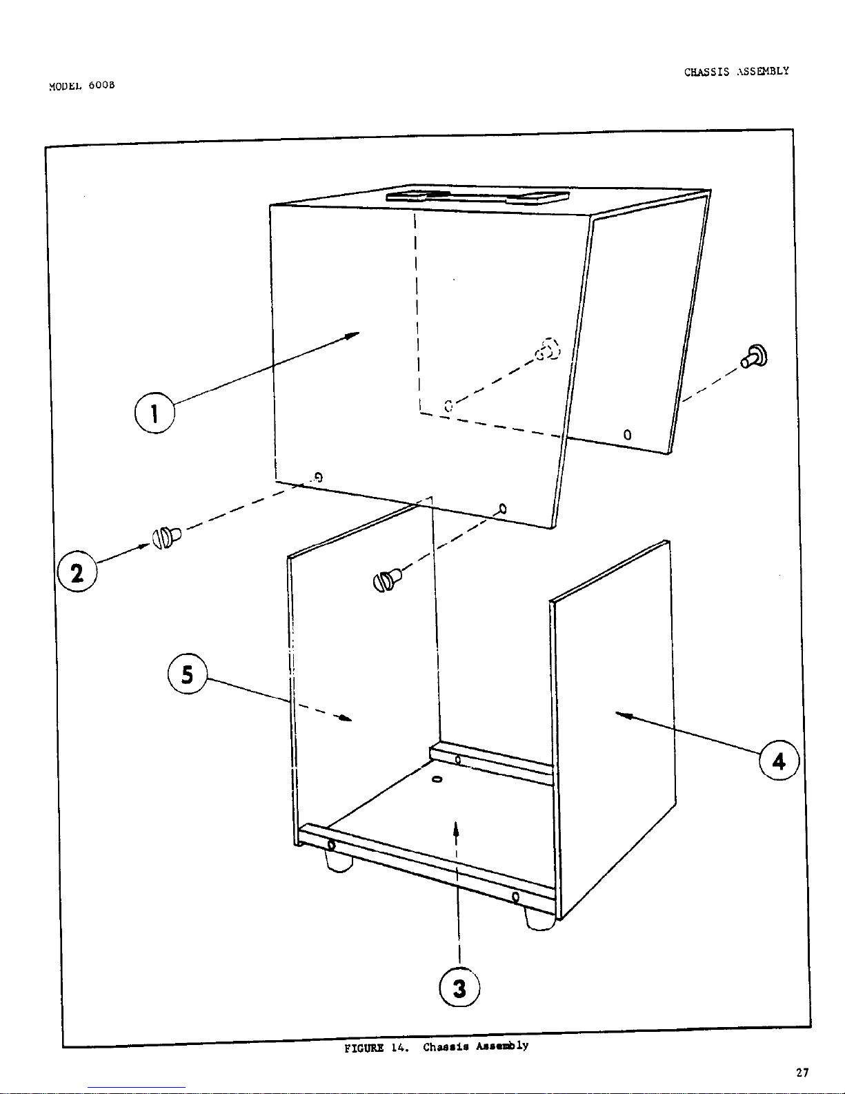
FIGURE 14.
ChU.i8 AmablY
Page 29

ii
r
t
i
 Loading...