

Page 1

Model 263
Quick Reference Guide
Calibrator/Source
Page 2

Page 3
INTRODUCTION
This quick reference guide contalne descriptions of parlous
features and Information concerning the operation of the
Model 283. Also included are programming examples using
VBrlous COntr011wa.
Q1997, Keithley Instruments. Inc.
Instruments Division
Document Number: 283-903-01 Rev. A
Cleveland. Ohio, U.S.A.
Page 4
TABLE OF CONTENTS
SAFETY PRECAUTlONS 3
FRONT PANEL OPERAflON 4
CONNECTORS IRear Panell.. 9
PROGRAMMING OUTPUT VALUES 10
SOURCING METHODS 11 ; ~
GUARD 13 ‘~I
FRONT PANEL PROGRAMS. 16 i
IEEE-488 PROGRAMMING.. 17
PROGRAMS 23
IBM PC or AT ICEC PC < > 488 Interface1 24
IBM PC or AT ,National GPIS PC Interface,. 26
APPLE II 28
HP85................................ 30
HPSERlES300and.9816 ,,,,,,,,,,,,,.,,, 32 ; j I
HP9925A............................. 34 :
DECLSIll ,...,,.,,,,,,,,,,,o,,,,.,,, 36 i ,! _
: j
i i
Page 5

SAFETY PRECAUTIONS
1. Before operation, ground the instrument through a properly earth grounded power receptacle.
2. Before sevlcing, disconnect the instrument from the
power line and all other equipment, and consult the Model
263 InstructIon Manual.
3. Do not touch any terminals while the Instrument Is oonnectsd to any other test equipment.
3
Page 6
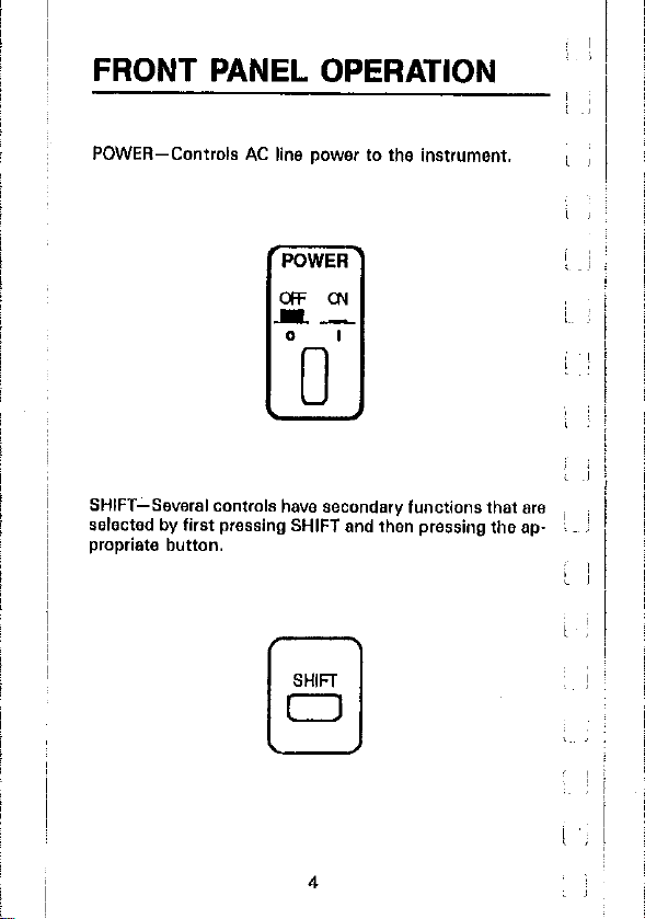
FRONT PANEL OPERATION
I
POWER-Controls AC line power to the instrument.
SHIFT-Several controls have secondary functions that are
selected by first pressing SHIFT and then pressing the ap- 1 :
propdate button.
i ;
I
~I
1~~ >
: I
,
Page 7
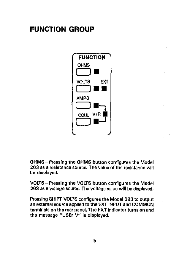
FUNCTION GROUP
FUNCTION
OHM9
o=
VOLTS EX
OmH
AMPS
f=-l
OYA V/R m
OB-'
OHMS-Pressing the OHMS button configures the Model
263 as a resistance source. The value of the reslstanoe will
be displayed.
VOLTS-Pressing the VOLTS button conflgures the Model
263 88 a voltage 80”~~ The voltage VBIUB will be displsyed.
Pressing SHIFT VOLTS configures the Model 263 to output
an external wurce applied to the EXT INPUT and COMMON
terminals on the rear panel. The EXT indicator turns on and
the message “USE, V” 18 displayed.
Page 8
AMPS-Pressing the AMPS button configures the Model :
263 as an active current source. The programmed current
value will be dlsplayed.
Pressing SHIFT AMPS turns on the V/R light indicating that
the Model 263 is configured as a passive current aouroe.
COUL-Pressing the COUL button conflgures the Model
263 8s an active charge 8ouroe. The currently selected :
range and programmed charge value will be displayed.
Pressing SHIFT COUL turns on the VIR light indicating that
the Model 263 is configured as a passive charge source.
CONTROLGROUP
I
’ ’
6
Page 9
RANGE-These two buttons are used to swleot the range
of the selected function. RANGE A upranges the Instrument and RANGE V downranges.
CURSOR-These two buttons are used to position the oursot when using the Adjust Method to modify an output
valuw. CURSOR C moves the cursor from left to right and
conversely, CURSOR 4 moves the cursor from right to left.
Not functional In OHMS.
Pressing SHIFT ON/OFF the first time displays the flashing
cursor continually. Pressing It again disables the cursor. Not
functional in OHMS.
ADJUST-These two buttons aro used to modify the display
reading using the Adjust Method. ADJUST A increments
the reading at the seleotnd dlglt and ADJUST T decrements
the reading. Not funotional in OHMS.
KEYPAD/ENTER-Pressing this button enables the keypad
allowing an output value to be keyed in using the number
10 through 91 buttons and the + button IKeypad Method).
Pressing this button *gain enters the resdlng and disables
the keypad. Not functional in OHMS.
SHIFT CANCEL-Pressing this button after keying in B
reading (Keypad Method) canoels that reading and disables
the keypad.
+/- Toggles the displayed reading (except OHMS1 betwsen posltlve (t) and negative l-l polarity. Not functional
in OHMS.
ZERO-Toggles the display between zero and the previously
displayed reading.
SHIFT GUARD-Toggles the output configuration between
guarded and unguarded.
7
Page 10
MENU-Used to Sslsot front panel program& Program
parameters are modified by the ADJUST buttons. Pressing
MENU after modifying a program parsmeter enters the new
parameter and returns the instrument to normal operation.
OPERATE-Toggles the instrument between the standby and
operate conditions.
8
Page 11
CONNECTORS (Rear Panel)
OUTPUT-Output high is available at this triax connector
ion the center conductor). Output low is available here Ion
the inner shield) or at the COMMON terminal depending
an the configuration of the output kmguarded or guarded).
EXT INPUT-This banana plug is used to connect an exter-
nal input (2OOV. lOOmA peak1 to the Model 2133. The ex-
ternal Input is then available at ths output of the Model 283
when VOLTS EXT is selected.
COMMON-Output low Is always avsllable at this termlnsl
regardless of the oonflguration of the output.
PREAMP OUT-This terminal along wlth COMMON can be
used to monitor the voltage drop across a load when the
instrument is sourcing current or charge. This termlnsl can
also be used as an external guard drive when sourcing
AMPS or COUL. PREAMP OUT is inoperative in AMPS V/R.
COUL V/R, VOLTS and OHMS.
IEEE CONNECTOR-Used to connect the instrument to the
IEEE-488 bus. IEEE interface functions are marked above
the connector.
AC RECEPTACLE-Power is applied through the supplied
power cord to the 3-terminal AC receptacle.
9
Page 12
PROGRAMMING OUTPUT
VALUES
_
For all functions, except OHMS, the following two data entry
methods can be used to program the instrument for 8” output value. In general, use the Adjust Method to modify B
value and the Kevpad Method to enter a completelv new
v.aIuB.
Adjust Method
1. Position Cursor. Using CURSOR 4 and CURSOR C, place
the cursor on the digit to be changed. To continuallv :
display the cursor location, press SHIFT ON/OFF.
2.Adjust Display Reading. Use thB ADJUST A and ADJUST
v to increment or decrement the reading. Polarity of the
reading is toggled by the +/- button.
Keypad Method
1. Enable Keypad. Enable the keypad by pressing KEYPAD/
ENTER. Keypad LED turns on.
2.Key In Reading. Key in the reading by pressing the BPpropriate number button (0 through 91 at each oursor
location. Polarity is toggled by the +/- button.
Note: If it is desired to cancel the keyed in reading and
return to the previously programmed value, press SHIFT
CANCEL. The keypad will disable.
3.Enter Reading. Again press KEYPAD/ENTER to enter the
displayed reading and disable the keeypsd. Keypad LED
turns off.
: ;
,~ I I
I
~
‘-
:
:
10
Page 13
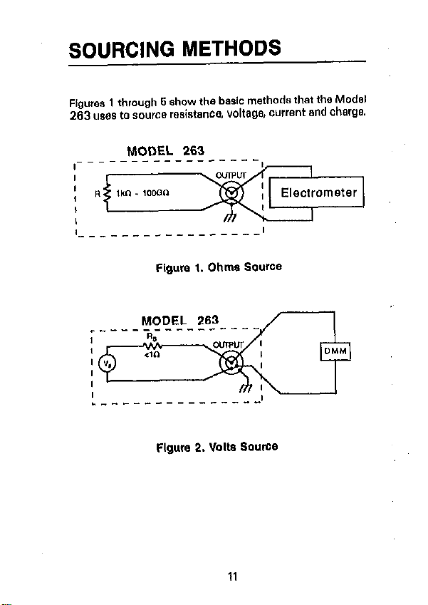
SOURCING METHODS
Figures 1 through 6 show the basic methods that the Model
263 ums to source resistance, voltage, current and charge.
MODEL 263
_ _ _ _ _ _ - - _ _ _ - - - - - 1
Flgure 1. Ohms Source
Flgum 2. Volts Source
11
Page 14

[ .j
Flgum 3. External Source
MODEL 263
r___-_____-_-_
L- _-__
---------,
Flgure 4. AMPS V/A and COUL V/A
Flgum 5. Amps and Coul Source
12
j !
l-=--t--
,
Page 15

GUARD
In the normal unguarded output con‘iguratlan, o”tp”t high
is connected to the center conductor of the triax OUTPUT
connector and outp,” low is connected to the Inner shield
Isee Figure 8). When the o”tput of the Mods1 203 18 placed I” the guarded conflguration, by pressing SHIFT GUARD,
output low Is disconnected from the inner shield of the OUT.
PUT connector ellowlng a guard drive to be connected to
it. In AMPS and COUL the guard drive is provided
by the Model 283. On the other functions (AMPS V/R, COUL
V/R, OHMS and VOLTS), the inner shield of the triax OUTPUT connector Is floating unles8 a guard drive is supplied
by the user. Figures 7 through 10 show the guarded output configurations for all functions.
Guarding 18 recommended for r~slstancw8 2 100Mg. Gusrding is not necessary when the Model 263 is sourcing current to a feedback picoammeter since this oircult is already
guarded. The low Input voltage burden of a feedback picommeter results with virtually the some voltage 0” output
high and low. Guarding Is recommended when sourcing current or charge to a high impedance load. Guarding Is un“~CBSSB,~ when sourcing voltage.
0ulPU-l
HI
LO
3
COMMON
Flgure 6. Normal (Unguarded) Output ConfIguration
13
Page 16

Flgure 7. Guarded Ohms Output Conflgurstlon
OUTPUT
:----_HL-
r----
$t_l
It--
Flgum 8. Guarded AMPS WA and guarded COUL V/R
output Co”llguratlo”
L ~~’
Page 17

Flgum S. Gusrdsd Amps and guarded Coul Output
Co”flguratlon
HI
OUTPUT
+
V.
c
I.0
Figure 10. Guarded VOLTS OUtput Conflgumtlon
16
Page 18

FRONT PANEL PROGRAMS
The available front panel programs are summarized in
Table 1. Perform the following steps to use B program:
1. Display the desired program using the MENU button.
2. Use the ADJUST A or ADJUST 7 button to change the
program pammeter.
3. To enter the new program paramter, press the MENU button again. The instrument will return to normal operation.
Note: The IEEE address fProgram IEEE1 and the display
mode IProgram dlSPl are stored in memory. Thus, the :~~ i
instrument will power-up to the programmed parameters.
Temperature compensation status is not stored and will I
always power up enabled Ill.
Table 1. Front Panel Programs
Check or change IEEE-488 bus address 10
Selects alternate display mode; engineering units lpi or scientific notation l-61.
Check or change temperature compensa-
Page 19

IEEE-488 PROGRAMMING
DEVICE-DEPENDENT COMMANDS
EKeCUte
X
Execute other device-dependent
commands
17
Page 20

Ohms Amps
Auto on Auto on A”,0 0” A”,0 0” fluto cl”
to k”
lock”
lcJM” 20llA 20 v 200°C WGL
lOOM” 200 nA 20 v
IOG”
lOOGO
1000”
IOOG” 20mA 20 V ZOOtiC ,OOGL
2 pA 2OLh” 2opc
1 k”
20 PA
200 PA 20 ” 2°C
tfm 2llA 20 ”
1G” 2pA 20 ”
2OpA 20 ” 20qk IOOGL
200 pA 20 V 200,X
2mA 20 ” ZOO& IOOGL
A”*0 Off A”,0 Off Auto Off Auto Off A”to Off
zero
Zero Off
:7
Zero on
Temperature Compensation
co
c,
Temperature compensation off
Tempsrsture ccmp~n~aticn on
Quml
wo
Wl
Guard Off
Guard On
vcns CO”, Ladder
IML
2 v 2oopc
20°C
2O#C lOOGL
m”ll.
,CCML
1GL
2pc 1OOGL
1OOGL
~
I
( I
18
:, j ~
Page 21

Self-Te@l
JO Perform self-test
EOI
KO
Kl
Enable EOI
Disable EOI
SRO
Disable
IYGi
Ml6
M32
Charge done
Resdv
ENC,
Ccdlbratlon Value
An
1 Calibrate using value
19
Page 22

Calfbmllon Value
Lfl
1 Calibrate low temperature cal point
output Value
V” Program output using value
PI&l
GO
Gl
Reading with prefix
Reading without prefix
operate
00 Standby
: 01 operate
20
Page 23

DATA FORMAT
SRQ MASK end STATUS BYTE FORMAT
21
Page 24

22
Page 25

PROGRAMS
23
Page 26

IBM PC or AT
(CEC PC < > 488 Interface)
The following program sends e command string to the
Model 263 from an IBM PC or AT computer end displays
the instrument reading string on the CRT. The computer
tnuet be equipped with the CEC lnterfaos and the DOS 2.00
lx later revisicnl cpereting system.
DIRECTIONS
1. Using the front panel prcgrem feature, set the primary
address of the Model 263 to 9.
2. With the power off, connect the Model 263 to the
IEEE-499 interface installed in the IBM computer.
3. Type in SASICA on the computer keyboard to get into
the IBM interpretive BASIC Ienguage.
4. Enter the lines below using the return key after eech line.
6. Run the program and type in the desired command string.
For example, to place the instrument in the current func-
tion end ZOO,& range, type in FIRSX and press the return
key.
6. The instrument reading string will then appear on the
dlsplsy.
24
Page 27

PROGRAM
COMMENTS
to OEFSEC.&HC408
’ Memory address.
20INtTIALIZE=O
30SEt40=9:ENTER=21 ’ Routine addresses.
40 MY. RDDRESS%=2I
’ PC < > 468 address.
50 INST. ADmESS%= ’ 263 address.
System ccntmller.
ln1t1el1ze evetetn.
Prompt for string.
Send commend string.
Meke room for dete.
Get readlna from 263.
NOTE: For conversion to numeric variable, make the fcllcwlng changes:
26
Page 28

IBM PC or AT
(National GPIB PC Interface)
The following program sends a command string to the
Model 263 from an IBM PC or AT computer and displays
the instrument reading string on the CRT. The computer
must be equipped with the National GPIB PC Interface and
the DOS 2.00 (or later revision) operating system. Interface
software must be Installed and configured as described in
the instruction manual.
1. Using the front panel program feature, set the primary
address of the Model 263 to 9.
2. With the power off, connect the Mods, 263 fo the
IEEE-489 interface installed in the IBM computer.
3. Type in BASICA on the computer keyboard to get into
the IBM interpretive BASIC language.
4. Place the interface software disk in the default drive, type
LOAD”DECL”, and press the ret”,” key.
5. Add the lines below to lines l-6 which are now in
memory. Modify the address in lines 1 and 2, as described
in the National instruction manual.
8. Run the program and type in the desired command string.
For example, to place the instrument in the current function and 200@ range, type in FlR9X and press the return
key.
7. The instrument reading string will then appear on the
display.
8. Ta exit the program, type in EXIT at the command prompt
and press the return key.
26
Page 29

PROQRAM
COMMENTS
Set primary sddress to 8.
50U%.RH182’ChLL IBPOKE
Set timeouts.
<BRDB%!U%>
60 w=t :cfiLL IBSRE
Set REN We.
CBRDO%,U%>
70 INPUTS 1 CCNMRND
Prompt for command.
STRIIG” icm*
80 IF cm$=* 1 EXIT” THEN See If program Is to be
150
90 IF c1,**=
“ 3, THEN,‘B
halted.
Check for null input.
108 CRLL IBHRT~W~~%~CMD~~ Address 263 to listen,
send string.
,,0RLw=SPRCE*~LBO>
Define reading input
buffer.
120 CALL IBRD<11263%,ROB~
Address 263 to talk, get
reading.
130PRINTRW
140 GOT0 70
150 I,%iBi CclLL IB”l,lL
Display the string.
Repeat.
Close the instrument file.
<P,263%,u%)
160 WLL ,BONL<BRDO%P u%> Close the board file.
L70 END
NOTE: For conversion to numerio varlsble, make the following changes:
Page 30

APPLE II
(Apple II IEEE-488 interface)
The following program sends a command string to the ;
Model 263 from an Apple II computer and displays the instrument reading string on the computer CRT.
The computer must be equipped with the Apple II IEEE-466
Interface installed in slot 3.
DIRECTIONS
1. Using the front panel program feature. set the primary 1~ 1 ‘:
address of the Model 263 to 6.
2,With the power off, connect the Model 263 to the j !
IEEE-466 interface installed in the Aoole II computer.
3. Enter the lines in ths program below, &ins the FliTURN
key after each line.
4. Run the program and tvps in the desired command String
at the command prompt. For example, to place the instrumsnt in the current function and 200pA range. type
in FtRgX and press the return key.
6. The instrument reading string will then appear on the
CRT.
26
;
_~I
i,
Page 31

PROORAM
COMMENTS
18Z*=CHRP<26>
20 INPUT ‘COPIIIH,~ID
STR,NG”iB*
30 PM3
40 IN”3
50PRINT“KA”
60PRINT”WT~“iZ*iB* Address 263 to listen,
70PRINT “LFI”
80PAlNT ~‘RDH”iZ*i: Address 263 to talk,
IIIPUT“ 3 ‘iA
98PRIHT1’UT”
160 PR#O
116 IN”6
120PRlHTAb
130 CDT0 20
Terminator.
Prompt for and enter
string.
Set output tom IEEE bus.
$ne input from IEEE
Enable remote.
send string.
Line Feed on.
G%:
Untalk the 263.
Define o”tp”t to CRT.
Define Input from
keyboard.
Display reading string.
Repeat.
NOTE: If conversion to numeric variable is required. make
the following changes:
29
Page 32

HP 85
The following program sends a command string to the : ~
Model 263 fraom an HP-66 computer and displays the instrmvwnt reading string on the computer CRT. The oomputer must be equipped with the HP82937 GPIB Interface : :
and an l/O ROM.
DIRECTIONS
I. Using the front panel progrsm feature, sot the primary
address of the Model 263 to 8.
2. With the power off, connect the Model 263 to the : ~.
HP82937A GPl6 interface installed in the HP-66
oornputer,
3. Enter the lines in the program below, using the END LINE ‘~
key after each line.
4. Press the HP-86 RUN key and type in the desired corn- ’ ’
msnd string at the command prompt. For example, to
place the instrument in the current function and 200~A ; ~
range, type in FlASX and press the END LINE key.
6. The instrument reading string will then appear on the in j
CRT.
( 1
30
Page 33

PROGRAM
COMMENTS
Prompt for command.
Input command string.
Address 283 to listen.
send strln
Address 2
put reading.,
:: 3 to talk, In-
R;;isp;y readlng string.
31
Page 34

HP SERIES 300 and 9818
The following program sends a command string to the
Model 263 from a Hewlett-Packard Ssries 300 or Model
9816 computer and displays the inwument reading strina
on the computer CRT. The computer mwt be equipped with
the HP62937 GPIB Interface and SASICA 4.0.
DIRECTIONS
1. Using the front panel program feature, set the primary
address of the Model 283 to 8.
2. With the power off, connect the Model 203 to the
HPS2937A GPIB interface installed in the computer.
3. Enter the lines In the program below, using the ENTER
key after each line.
4. Press the RUN key end type in the desired command
string at the command prompt. For example, to place tha
instrument in the current function and 200~A range, type
I” FlA9X and press the ENTER key.
6. The instrument resdlng string will then appew on the
CRT.
32
Page 35

PROGRAM
COMMENTS
Place 263 I” r*rnct*.
Prompt for and Input
command.
Address 203 to listen,
send string.
Address 263 tc talk. In-
put readlng.
Display reading string.
Repeat.
NOTE: For ccnverslon tc a numeric variable, change the prcgram as follows:
33
Page 36

HP 9825A
Use the fcllowlng~prcgrsm to send a command string to
the Model 263 from a Hewlett-Packard Model 9826A and
display the instrument reading string on the computer
printer. The computer must be equipped with the
HP99034A HP16 Interface and a 9972A extended I/O ROM.
DIRECTIONS
1. From the front panel, set the primary address of the Model
263 to 13.
2.With the power off, connect the Model 263 to the
99034A HPIB interface installed in the 992SA.
3.Enter the lines in the program below, using the STORE
key after each line Line numbers are automatically assigned by the 9926A.
4.Press the 982SA RUN key and type in the desired ccm-
msnd string at the command prompt. For example, to
place the Instrument in the current function and ZOOpA
range. type in FlR9X and press the CONT key.
&The instrument reading string will then appear on the
computer print cut.
34
Page 37

PROGRAM
COMMENTS
0 dim AX251 9 LW201
1dev”263”,708
2 rernl1263’)
3 env ~COMIIAND STRING” I
7 gtc 3
NOTE: For conversIon to numerlo variable, modify the prcgram 88 follows:
Olmensicn data strings.
De,,ne 283 at address
Place 263 in remote.
Prompt for command
string.
Address 263 to lIsten,
send 8trlng.
.44ry 263 to talk, input
Print data strlnp on
printer. Repeat.
8.
6 prt val(00[51)
36
Page 38

DEC LSI 11
The following program sends a command string to the :
Model 283 from a DEC LSI 11 minicomputer and displays
the instrument reading string on the DEC CRT terminal. The
LSI 11 must be configured with IBK words of RAM and 8” 1~
IBV 11 IEEE-489 interface. The software must be configured
with the IB software as well 88 FORTRAN and the AT 11 i
operating system.
1. Using the front panel program feature, set the primary i
address of the Model 263 to 8.
2,With the power off, connect the Model 263 to the IBV I
11 IEEE-488 interface cable.
3. Enter the program below, using the editor under FIT 11 i
and the name IEEE.FOR.
4.Comcile using the FORTRAN ccmeilsr as follows: FORTRAN IEEE. -
6.Link with the svstern and IB libraries as follows: LINK
IEEE,IBLIB.
&Type RUN IEEE and press the RETURN key.
7.The display will read “ENTER ADDRESS”.
B.Typs in B and press the RETURN key.
9.The display will read “TEST SETUP’:
10. Type in the desired command string and press the
RETURN key. For example, to program the instrument
for the current function and 200~A range, type in FlRSX
and press RETURN.
11. The Instrument data string will appear an the computer i
display.
~
36
Page 39

PROGRAM
COMMENTS
DO2I=I,lB
CALLIBSTER<IIFl)
2 CONTINUE
CALLIBSTER<i5,5>
C*LLIBTtMc~t20~
PRIADR)
18 I=,8REC”<IHPlJT,80r
PRIADR)
IHPUT~I+L~=O
CRLLPUTSTR<7rINPUTl
‘6’)
COLL lBUNT
GOT0 12
END
Turn off IE errors.
Allow 6 error 16’s.
Allow 1 second bus
dmsc”t.
Set line feed as
terminator.
lbrn on remote.
Input primary address.
send 8trlng.
Get data from
instrument.
Untslk the 263.
Repeat.
37
Page 40

Page 41

Page 42

 Loading...