

Page 1

Model 2470
tek.com/keithley
High Voltage SourceMeter
User’s Manual
2470-900-01 Rev. A / May 2019
®
Instrument
*P2470-900-01A*
2470-900-01A
Page 2

High Voltage SourceMeter Instrument
Model 2470
User's Manual
Page 3

© 2019, Keithley Instruments, LLC
Cleveland, Ohio, U.S.A.
All rights reserved.
Any unauthorized reproduction, phot ocopy, or use of the information herein, in whole or in part,
without the prior written approval of Keithley Instruments, LLC, is strictly prohibited.
These are the original instructions in English.
TSP®, TSP-Link®, and TSP-Net® are trademarks of Keithley Instruments, LLC. All Keithley
Instruments product names are trademarks or registered trademarks of Keithley Instruments, LLC.
Other brand names are trademarks or registered trademarks of their respective holders.
Microsoft, Visual C++, Excel, and Windows are either registered trademarks or trademarks of
Microsoft Corporation in the United States and/or other countries.
Document number: 2470-900-01 Rev. A / May 2019
Page 4

Safety precautions
The following safety precautions should be observed before using this product and any associated instrumentation. Although
some instruments and accessories would normally be used with nonhazardous voltages, there are situations where hazardous
conditions may be present.
This product is intended for use by personnel who recognize shock hazards and are familiar with the safety precautions required
to avoid possible injury. Read and follow all installation, operation, and maintenance information carefully before using the
product. Refer to the user documentation for complete product specifications.
If the product is used in a manner not specified, the protection provided by the produc t warranty may be impaired.
The types of product users are:
Responsible body is the individual or group responsible for the use and maintenance of equipment, for ensuring that the
equipment is operated within its specifications and operating limits, and for ensuring that operators ar e adequately trained.
Operators use the product for its intended function. They must be traine d in electrical safety procedures and pr oper use of the
instrument. They must be protected from electric shock and contact with h azardous live circuits.
Maintenance personnel perform routine procedures on the product to keep it operating properly, for example, setting the line
voltage or replacing consumable materials. Maintenance procedures ar e described in the user documentation. The procedures
explicitly state if the operator may perform them. Otherwise, they should be performed only by service personnel.
Service personnel are trained to work on live circuits, perform safe installations, and repair products. Only properly trained
service personnel may perform ins tallation and service procedures.
Keithley products are designed for us e with electrical signals that are measurement, control, and data I/O connecti ons, with low
transient overvoltages, and mus t not be directly connected to mains voltage or to voltage sources with high tr ans ient
overvoltages. Measurement Categ ory II (as referenced in IEC 60664) connections require protection for high transient
overvoltages often associated with local AC mains connections. Certai n K ei thley measuring instruments may be connected to
mains. These instruments will be mar k ed as category II or higher.
Unless explicitly allowed in the spec i fications, operating manual, and instrument labels, do not connect any instrument to mains.
Exercise extreme caution when a shock hazard is present. Lethal voltage m ay be present on cable connector jacks or test
fixtures. The American National S tandards Institute (ANSI) states that a shock hazard exists when voltage levels greater than
30 V RMS, 42.4 V peak, or 60 VDC are present. A good safety practice is to expect that hazardous voltage is present in any
unknown circuit before measuring.
Operators of this product must be protec ted from electric shock at all times. The responsible body must ensure that operators
are prevented access and/or insulated from every connection point. In some c ases, connections must be exposed to potential
human contact. Product operators i n these circumstances must be trained to pr otect themselves from the risk of electric shock. If
the circuit is capable of operating at or above 1000 V, no conductive part o f the circuit may be exposed.
Do not connect switching cards direc tly to unlimited power circuits. They are intended to be used with impedance-limited
sources. NEVER connect switching cards directly to AC mains. When conn ec ting sources to switching cards, ins tall protective
devices to limit fault current and v ol tage to the card.
Before operating an instrument, ensure that the line cord is connected to a properly-grounded power receptacle. Inspect the
connecting cables, test leads, and j umpers for possible wear, cracks , or breaks before each use.
When installing equipment where ac cess to the main power cord is restricted, such as rack mounting, a separate main input
power disconnect device must be provided in close proximity to the equipment and within easy reach of the operator.
For maximum safety, do not touch the product, test cables, or any other instruments while power is applied to the circuit under
test. ALWAYS remove power from the entire test system and discharge any ca pac i tors before: connecting or disconnecting
cables or jumpers, installing or rem oving switching cards, or making int er nal changes, such as installing or removing jumpers.
Do not touch any object that could provide a current path to the common side of the c i rcuit under test or power line (earth)
ground. Always make measurements with dry hands while standing on a dry, insulated surface capable of withstandin g the
voltage being measured.
Page 5

For safety, instruments and accessories must be used in accordance with the operating instructions. If the instruments or
accessories are used in a manner not s pecified in the operating instructions, the protection provided by the equipment may be
impaired.
Do not exceed the maximum signal lev els of the instruments and accessories . Maximum signal levels are defined in the
specifications and operating inf or mation and shown on the instrument panels, test fixture panels, and switching cards.
When fuses are used in a product, replac e with the same type and rating for continued protection against fire hazard.
Chassis connections must only be used as shiel d connections for measuring circuits, NOT as protective earth (safet y ground)
connections.
If you are using a test fixture, keep the lid closed while power is applied to the device under test. Safe operation requir es the use
of a lid interlock.
If a
The
screw is present, connect it to prot ective earth (safety ground) using the wire r ecommended in the user documentation.
symbol on an instrument means caution, risk of hazard. The user must refer to t he operating instructions located in the
user documentation in all cases where the symbol is marked on the instrument .
The symbol on an instrument means warning, risk of electric shock. Use standard saf ety precautions to avoid personal
contact with these voltages.
The
The
If this
symbol on an instrument shows that the surface may be hot. Avoid personal contact to prevent burns.
symbol indicates a connection termin al to the equipment frame.
symbol is on a product, it indicates th at mercury is present in the display lamp. Please note that the lamp must be
properly disposed of according to federal, state, and local laws.
The WARNING heading in the user documentation explains hazards that might result in personal injury or death. Always read
the associated information ver y carefully before performing the indicated procedure.
The CAUTION heading in the user documentation explains hazards that could damage the inst rument. Such damage may
invalidate the warranty.
The CAUTION heading with the
symbol in the user documentation explains hazards that could result in m oder ate or minor
injury or damage the instrument. Always read the associated information very carefully before performing the indicated
procedure. Damage to the instrument may invalidate the warranty.
Instrumentation and accessories s hall not be connected to humans.
Before performing any maintenance, disconnect the line cord and all test cables.
To maintain protection from electric shock and fire, replacement components in mains circuits — including the power
transformer, test leads, and input j ac ks — must be purchased from Keithley. S tandard fuses with applicable national safety
approvals may be used if the rating and type are the same. The detachable mains p ower cord provided with the instrument may
only be replaced with a similarly rated power cord. Other components that ar e not safety-related may be purchased from other
suppliers as long as they are equivalent to the original component (note tha t selected parts should be purchased on ly through
Keithley to maintain accuracy and f unctionality of the product). If you are unsure about the applicability of a r eplacement
component, call a Keithley office for information.
Unless otherwise noted in product-specific literature, Keithley instruments are designed to operate indoors only, in the following
environment: Altitude at or below 2,000 m (6,562 ft); temperature 0 °C to 50 °C (32 °F to 122 °F); and pollution degree 1 or 2.
To clean an instrument, use a cloth dampened with deionized water or mild, water-based cleaner. Clean the exterior of the
instrument only. Do not apply cleaner directly to the instrument or allow liquids to enter or spill on the instrument. Products that
consist of a circuit board with no case or chassis (e.g., a data acquisition board for installation into a computer ) should never
require cleaning if handled according to instructions. If the board becomes contaminated and operation is affected, the board
should be returned to the factor y for proper cleaning/servicing.
Safety precaution revision as of J une 2017.
Page 6

Page 7

Table of contents
Introduction ................................................................................................................ 1-1
Welcome .............................................................................................................................. 1-1
Introduction to this manual ................................................................................................... 1-2
Extended warranty ............................................................................................................... 1-2
Contact information .............................................................................................................. 1-2
Organization of manual sections .......................................................................................... 1-2
Applications .......................................................................................................................... 1-3
Front-panel overview ................................................................................................. 2-1
Power the instrument on or off ............................................................................................. 2-1
Front-panel overview ............................................................................................................ 2-3
Turn the 2470 output on or off ............................................................................................. 2-5
Touchscreen display ............................................................................................................ 2-6
Select items on the touchscreen ............................................................................................... 2-6
Interactive swipe screens .......................................................................................................... 2-7
Menu overview ........................................................................................................................ 2-10
Store measurements on a USB flash drive ........................................................................ 2-10
Save screen captures to a USB flash drive ....................................................................... 2-11
Using a remote interface ........................................................................................... 3-1
Remote communications interfaces ..................................................................................... 3-1
Supported remote interfaces ................................................................................................ 3-1
GPIB communications .......................................................................................................... 3-2
Install the GPIB driver software ................................................................................................. 3-2
Install the GPIB cards in your computer .................................................................................... 3-2
Connect GPIB cables to your instrument .................................................................................. 3-2
Set the GPIB address ............................................................................................................... 3-4
LAN communications ........................................................................................................... 3-4
Set up LAN communications on the instrument ........................................................................ 3-5
Set up LAN communications on the computer .......................................................................... 3-6
USB communications ........................................................................................................... 3-7
Connect a computer to the 2470 using USB ............................................................................. 3-8
Communicate with the instrument ............................................................................................. 3-8
Using the web interface ...................................................................................................... 3-12
LAN troubleshooting suggestions ............................................................................................ 3-13
Web interface Home page....................................................................................................... 3-14
Identify the instrument ............................................................................................................. 3-14
Review events in the event log ................................................................................................ 3-15
Determining the command set you will use ....................................................................... 3-15
Page 8

Table of contents
User's Manual
Model 2470 High Voltage SourceMeter Ins trument
Making basic front-panel measurements ................................................................ 4-1
Introduction .......................................................................................................................... 4-1
Equipment required for this application ................................................................................ 4-2
Device connections .............................................................................................................. 4-2
Make front-panel measurements ......................................................................................... 4-3
How to make front-panel measurements .................................................................................. 4-3
Leakage current and insulation resistance ............................................................. 5-1
Introduction .......................................................................................................................... 5-1
Equipment required .............................................................................................................. 5-2
Set up remote communications ........................................................................................... 5-2
Device connections .............................................................................................................. 5-2
Measuring leakage current .................................................................................................. 5-4
Set up the leakage current application using the front panel ..................................................... 5-5
View the measurements on the front-panel graph ..................................................................... 5-6
Set up the leakage current application using SCPI commands ................................................. 5-7
Set up the leakage current application using TSP commands .................................................. 5-7
Measuring insulation resistance ........................................................................................... 5-9
Set up the insulation resistance application using the front panel ........................................... 5-10
Viewing the measurements on the front-panel graph .............................................................. 5-11
Set up the application using SCPI commands ........................................................................ 5-12
Set up the application using TSP comm ands .......................................................................... 5-13
Measure I-V characteristics of FETs ........................................................................ 6-1
Introduction .......................................................................................................................... 6-1
Equipment required .............................................................................................................. 6-2
Set up remote communications ........................................................................................... 6-2
Set up external hardware triggers ........................................................................................ 6-3
Connections for the SCPI command set ................................................................................... 6-3
Connections for the TSP command set ..................................................................................... 6-4
Device connections .............................................................................................................. 6-5
Drain leakage current measurement device connections .......................................................... 6-5
Subthreshold current or drain family of curves measurement device con nections .................... 6-7
Remote control of FET testing using SCPI commands ....................................................... 6-8
Set up the application using SCPI commands with the trigger model ....................................... 6-8
Set up the application using SCPI commands in a linear sweep ............................................. 6-11
Remote control of FET testing using TSP commands ....................................................... 6-13
Set up the drain leakage current measurement using TSP commands .................................. 6-13
Set up a subthreshold current measur em ent using TSP commands ...................................... 6-15
Set up the drain family of curves meas urement using TSP commands .................................. 6-18
Troubleshooting FAQs .............................................................................................. 7-1
About this section ................................................................................................................. 7-1
Page 9

Model 2470
of contents
High Voltage SourceMeter Instrument User's Manual Table
Where can I find updated drivers? ....................................................................................... 7-1
How do I upgrade the firmware? .......................................................................................... 7-2
Why can't the 2470 read my USB flash drive? .................................................................... 7-2
How do I change the command set? ................................................................................... 7-3
Why am I getting a 5074 event code? ................................................................................. 7-4
How do I save the present state of the instrument? ............................................................ 7-4
Why did my settings change? .............................................................................................. 7-5
What are the Quick Setup options? ..................................................................................... 7-6
Next steps ................................................................................................................... 8-1
Additional 2470 information ................................................................................................. 8-1
Page 10

Applications .............................................................................. 1-3
In this section:
Welcome
Thank you for choosing a Keithley Instruments product. The 2470 High Voltage SourceMeter
Instrument is a precise, low-noise instrument t hat combines a stable DC power supply with a
repeatable, high-impedance multimeter. T hi s instrument features intuitive setup and control,
enhanced signal quality and range, and better re sistivity and resistance capabilities than similar
products on the market.
Section 1
Introduction
Welcome .................................................................................. 1-1
Introduction to this manual ....................................................... 1-2
Extended warranty ................................................................... 1-2
Contact information .................................................................. 1-2
Organization of manual sections .............................................. 1-2
With its 1100 V and 10 fA capability, the 2470 is optimized f or characterizing and testing high voltage,
low leakage devices, materials, and modules, s uch as silicon carbide (SiC), gallium nitride (GaN),
power MOSFETs, transient suppression devices, circuit protection devices, power modules, and
batteries.
SMU instruments offer a highly flexible, four-quadrant voltage and current source/load coupled with
precision voltage and current measurements. T he 2470 instrument can be used as a:
• Precision power supply with voltage and curre nt readback
• True current source
• Digital multimeter (DCV, DCI, ohms, and power wit h 6½-digit resolution)
• Precision electronic load
• Pulse generator
• Trigger controller
Page 11

Section
User's Manual
1: Introduction Model 2470 High Voltage SourceMeter Ins trument
Introduction to this manual
This manual provides detailed applications to hel p you achieve success with your Keithley
Instruments 2470. In addition, this manual prov ides information about the basics of the front panel to
familiarize you with the instrument.
This manual presents an overview of each applic at i on, followed by instructions to complete the
application using the front panel, SCPI code, TSP code, or Keithley KickStart Startup Software.
More information about the commands that are use d i n these applications is available. Refer to the
SCPI and TSP command reference sections of the Model 2470 Reference Manual. This manual is on
tek.com/keithley
.
Extended warranty
Additional years of warranty coverage are available on many products. These valuable contracts
protect you from unbudgeted service expenses and p rovide additional years of protection at a fraction
of the price of a repair. Extended warranties are available on new and existing products. Contact your
local Keithley Instruments office, sales part ner, or distributor for details.
Contact information
If you have any questions after you review the information in this documentation, please contact your
local Keithley Instruments office, sales partner, or distributor. You can also call the corporate
headquarters of Keithley Instruments (toll -f ree inside the U.S. and Canada only) at 1-800-935-5595,
or from outside the U.S. at +1-440-248-0400. For worldwide contact numbers, visit the
Instruments website (tek.com/keithley).
Organization of manual sections
This manual is organized into the following sections:
• Front-panel overview (on page 2-1): Describes the basics of using the front-pane l i nterface.
• Using a remote interface (on page 3-1): Describes the basics of remote communicati ons and
using the instrument web interface.
• Application examples (see below): Provides detailed examples of how to use th e 2470 i n some
t
ypical situations.
• Troubleshooting FAQs (on page 7-1): Provides answers to frequently asked questions to help you
troubleshoot common problems encountered with the 2470.
• Next steps (on page 8-1): Provides information about additional resources that can help you use
the 2470.
Keithley
1-2 2470-900-01 Rev. A / May 2019
Page 12

Model 2470
Introduction
High Voltage SourceMeter Instrument User's Manual Section 1:
The PDF version of this manual contains bookmarks for each section. The manual sections are also
listed in the Table of Contents at the beginning of thi s manual.
For more information about bookmarks, see Adobe
Applications
This manual provides application examples t hat show you how to perform tests from the front panel
and over a remote interface. These applications are presented after the summary information about
the 2470. The applications include:
• Making basic front-panel measurements (on page 4-1): Demonstrates the basic measurement
functionality using a single 2470 and a two-terminal device under test (DUT).
• Leakage current and insulation resistance (on page 5-1): Demonstrates how to use a 2470 to
make high resistance measurements on two-terminal DUTs.
• Measure I-V characteristics of FETs (on page 6-1): Demonstrates how to use one or two 2470s to
verify and characterize field-effect transistors (FETs).
®
Acrobat® or Reader® help.
2470-900-01 Rev. A / May 2019 1-3
Page 13

Save screen captures to a USB flash drive ............................ 2-11
In this section:
Power the instrument on or off ................................................. 2-1
Front-panel overview ................................................................ 2-3
Turn the 2470 output on or off .................................................. 2-5
Touchscreen display ................................................................ 2-6
Store measurements on a USB flash driv e ............................ 2-10
Power the instrument on or off
Follow the steps below to connect the 2470 to line po wer and turn on the instrument. The 2470
operates from a line voltage of 100 V to 240 V at a f requency of 50 Hz or 60 Hz. It automatically
senses line voltage and frequency. Make sure the operating voltage in your area is compatible.
Section 2
Front-panel overview
You must turn on the 2470 and allow it to warm up for at least one hour to achieve rated accuracies.
Operating the instrument on an incorrect line voltage may cause damage to the instrument,
possibly voiding the warranty.
The power cord supplied with the 2470 contains a separate protective earth (safety ground)
wire for use with grounded outlets. When proper connections are made, the instrument
chassis is connected to power-line ground through the ground wire in the power cord. In
addition, a redundant protective earth connection is provided through a scre w on the rear
panel. This terminal should be connected to a known protective earth. In the event of a
failure, not using a properly grounded protective earth and grounded outlet may result in
personal injury or death due to electric shock.
Do not replace detachable mains supply cords with inadequately rated cords. Failure to use
properly rated cords may result in personal injury or death due to electric shock.
Page 14
Section
User's Manual
2: Front-panel overview Model 2470 High Voltage SourceMeter Ins trument
To connect the power cord:
1. Make sure that the front-panel POWER switch is in the off (O) position.
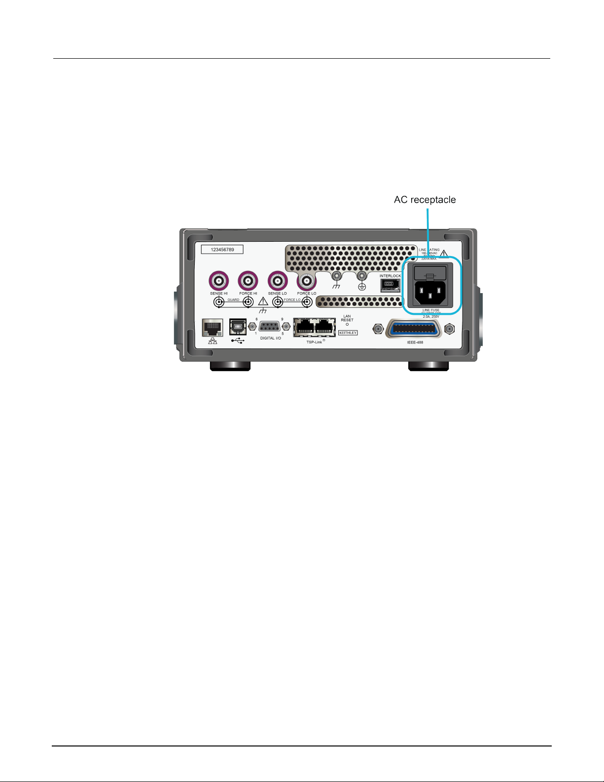
2. Connect the female end of the supplied power cord to the AC receptacle on the rear panel .
3. Connect the male end of the power cord to a grounded AC outlet.
Figure 1: Model 2470 AC receptacle on rear panel
To turn a 2470 on or off:
1. Before turning the instrument on, disconnect any devices under test (DUTs) from the 2470.
2. To turn your instrument on, press the front-panel POWER switch to place it in the on (|) position.
The instrument displays a status bar as it powe rs o n. The home screen is displayed when power
on is complete.
3. To turn your instrument off, press the front-panel POWER switch to place it in the off (O) position.
2-2 2470-900-01 Rev. A / May 2019
Page 15
Model 2470
panel overview
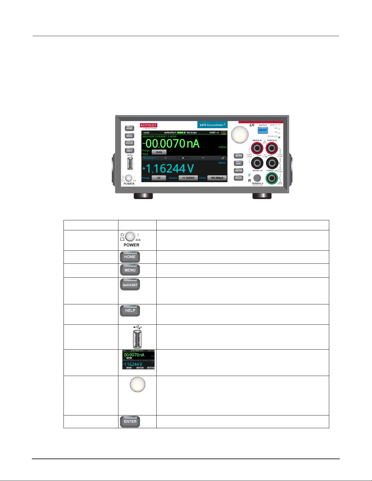
POWER switch
Turns the instrument on or off. T o turn the instrument on, press the
power switch so that it is in the off posi tion (O).
HOME key
Returns the display to the home scr een.
MENU key
Opens the main menu. Press the icons on t he main menu to open
source, measure, views, trigger, scripts, and system screens.
QUICKSET key
Opens a menu of preconfigured setups, including voltmeter,
resolution or speed.
HELP key
Opens help for the area or item that is selected on the display. If
overview information for the screen you are viewing.
USB port
Saves reading buffer data and scr een snapshots to a USB flash
Touchscreen
The 2470 has a high-resolution, fiv e -inch color touchscreen display.
MENU, QUICKSET, and FUNCTION keys.
Navigation control
Turning the navigation control: Moves the cursor to highlight a list
allows you to edit the selected field.
ENTER key
Selects the highlighted choice or allows you to edit the selected field.
High Voltage SourceMeter Instrument User's Manual Section 2: Front-
Front-panel overview
The front panel of the 2470 is shown below. Descriptions of the controls on the front panel follow the
figure.
Figure 2: Model 2470 front panel
Control Graphic Description
power switch so that it is in the on position (|). To turn it off, press the
ammeter, ohmmeter, and power sup ply. Also allows you to choose
source and measure functions and adjus t performance for better
there is no selection when you press the HELP key, it displays
drive. You can also store and retrieve scripts to and from a USB flash
drive. The flash drive must be form atted as a FAT or FAT32 drive.
The touchscreen accesses swipe screens and menu options. You
can access additional interact ive screens by pressing the front-panel
value or menu item so that you can select it. Turning the control when
the cursor is in a value entry field increases or decreases the value in
the field.
Pressing the navigation control: Selects the highlighted choice or
2470-900-01 Rev. A / May 2019 2-3
Page 16
Section
User's Manual
Returns to the previous screen or closes a dialog box. For example,
screen.
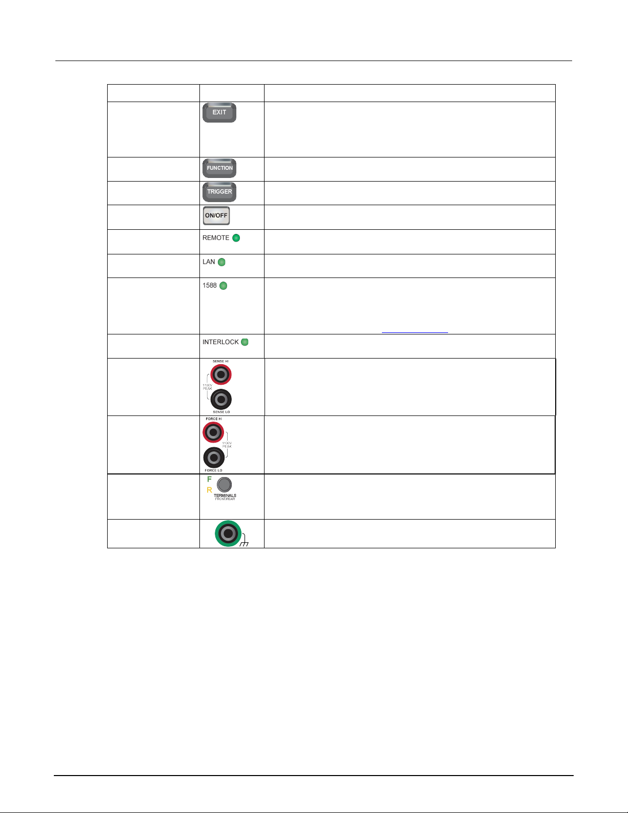
FUNCTION key
Displays instrument functions. To select a function, touch the function
name on the screen.
TRIGGER key
Accesses trigger-related settings and operations. The action of the
TRIGGER key depends on the instrument state.
switch
Turns the output source on or off. The switch illuminates when the
REMOTE LED
Illuminates when the instrument is controlled through a remote
LAN LED indicator
Illuminates when the instrument is connected to a local area network
(LAN).
2470 Release Notes on the tek.com/keithley for details.
INTERLOCK LED
indicator
Illuminates when the interlock is enabled.
SENSE terminals
Use the SENSE HI and SENSE LO terminal connections to measure
measurement of the voltage drop across the force leads is eliminated.
FORCE terminals
Use FORCE HI and FORCE LO terminal connections to source or
FRONT/REAR
Activates the terminals on the front or rear panel. When the
yellow "R" is visible to the left of t he switch.
Chassis connection
Banana jack connector that provides a chassis connection.
2: Front-panel overview Model 2470 High Voltage SourceMeter Ins trument
Control Graphic Description
EXIT key
press the EXIT key when the main menu is displayed to return to the
home screen. When you are viewing a subs creen (for example, the
Event Log screen), press the EXIT key to return to the main menu
OUTPUT ON/OFF
indicator
1588 LED indicator
TERMINALS switch
source output is on.
interface.
Illuminates when the instrument is connected to an IEEE-1588
compliant device.
Note that 1588 functionality is not supported at this time. This
functionality will be made available with a firmware update. See the
voltage at the device under test (DUT). When you use sense leads,
This produces more accurate voltag e sourcing and measurement at
the DUT.
sink voltage or current to or from a device under test (DUT).
front-panel terminals are activ e, a green "F" is visible to the left of the
FRONT/REAR switch. When the rear-panel terminals are active, a
2-4 2470-900-01 Rev. A / May 2019
Page 17

Model 2470
panel overview
High Voltage SourceMeter Instrument User's Manual Section 2: Front-
Turn the 2470 output on or off
You can turn the 2470 output on from the front panel or by sending remote commands.
Turning the 2470 output off does not place the instrument in a safe state (an interlock is
provided for this function).
Hazardous voltages may be present on all output and guard terminals. To prevent electrical
shock that could cause injury or death, never make or break connections to the 2470 while
the instrument is powered on. Turn off the equipment from the front panel or disconnect the
main power cord from the rear of the 2470 before handling cables. Putting the equipment into
an output-off state does not guarantee that the outputs are powered off if a hardware or
software fault occurs.
When the source of the instrument is turned off , it may not completely isolate the instrument from the
external circuit. You can use the Output Off setti ng to place the 2470 in a known, noninteractive state
during idle periods, such as when you are changing the device under test. The output-off states that
can be selected for a 2470 are normal, high-impe dance, zero, or guard.
See "Output-off state" in the 2470 Reference Manual for additional details.
Using the front panel:
Press the OUTPUT ON/OFF switch. The instrument is in the output-on state when the switch is
illuminated. The instrument is in the output-off state when the switch is not illuminated.
Using SCPI commands:
To turn the output on, send the command:
:OUTPut:STATe ON
To turn the output off, send the command:
:OUTPut:STATe OFF
Using TSP commands:
To turn the output on, send the command:
smu.source.output = smu.ON
To turn the output off, send the command:
smu.source.output = smu.OFF
2470-900-01 Rev. A / May 2019 2-5
Page 18
Section
User's Manual
2: Front-panel overview Model 2470 High Voltage SourceMeter Ins trument
Touchscreen display
The touchscreen display gives you quick front-panel access to source and measure settings, system
configuration, instrument and test status, reading buffer information, and other instrument functionality.
The display has multiple swipe screens that y ou can access by swiping the front panel. You can
access additional interactive screens by pres sing the front-panel MENU, QUICKSET, and FUNCTION
keys.
Do not use sharp metal objects, such as t weezers or screwdrivers, or pointed objects, such
as pens or pencils, to touch the touchscreen. It is strongly recommended that you use only
fingers to operate the instrument. Use of clean-room gloves to operate the touchscreen is
supported.
Select items on the touchscreen
To select an item on the displayed screen, do one of the following:
• Touch it with your finger
• Turn the navigation control to highlight the item, and then press the navigation control to select it
The following topics describe the 2470 touchscreen in more detail.
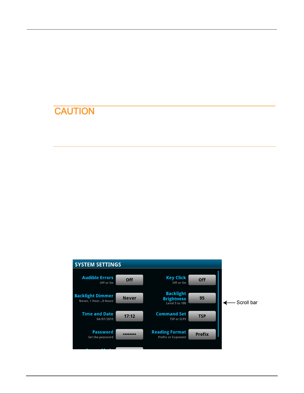
Some of the interactive screens have additional options that are only visible when you scroll down the
screen. A scroll indicator on the right side of the touchscreen identifies these screens. Swipe the
screen up or down to view the additional options.
The figure below shows a screen with a scroll bar.
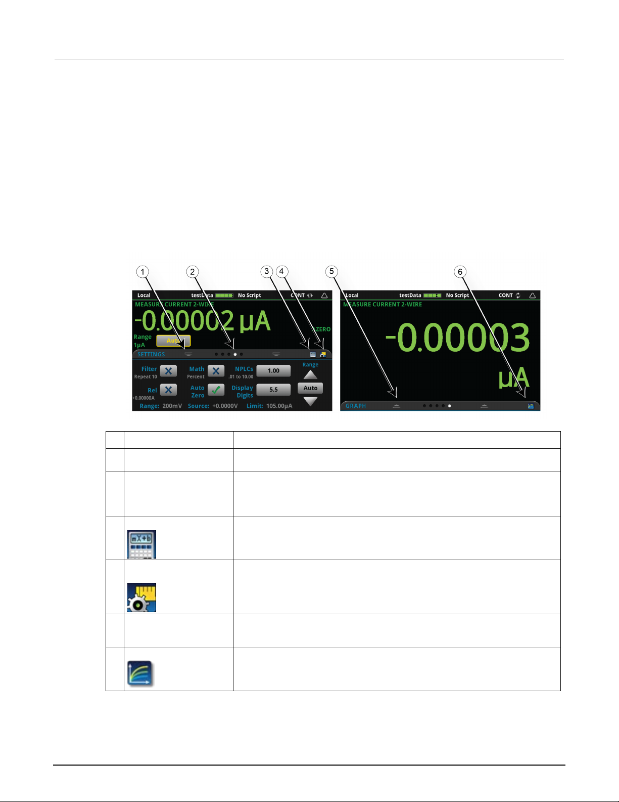
Figure 3: Touchscreen window with a scroll bar indicator
2-6 2470-900-01 Rev. A / May 2019
Page 19
Model 2470
panel overview
1
Minimize indicator
You can swipe down to minimize the swipe screens.
2
Swipe screen indicator
Each circle represents one swipe screen. As you swipe right or left, a diff er ent
3
Calculations shortcut
Select to open the CALCULATION SETTINGS menu.
4
Measure Settings
Select to open the MEASURE SETT INGS menu for the selected function.
5
Restore indicator
Indicates that you can swipe up to dis play the swipe screen.
6
Graph shortcut
Select to open the Graph screen.
High Voltage SourceMeter Instrument User's Manual Section 2: Front-
Interactive swipe screens
The 2470 touchscreen display has multiple scr eens that you can access by swiping left or right on the
lower half of the display. The options available in the swipe screens are described in the following
topics.
Swipe screen heading bar
The heading bar of the swipe screen contains the following options.
Figure 4: Swipe screens, maximized and mini m ized
# Screen element Description
circle changes color, indicatin g where you are in the screen sequence. Select a
circle to move the swipe screen without swiping.
shortcut
2470-900-01 Rev. A / May 2019 2-7
Page 20
Section
User's Manual
2: Front-panel overview Model 2470 High Voltage SourceMeter Ins trument
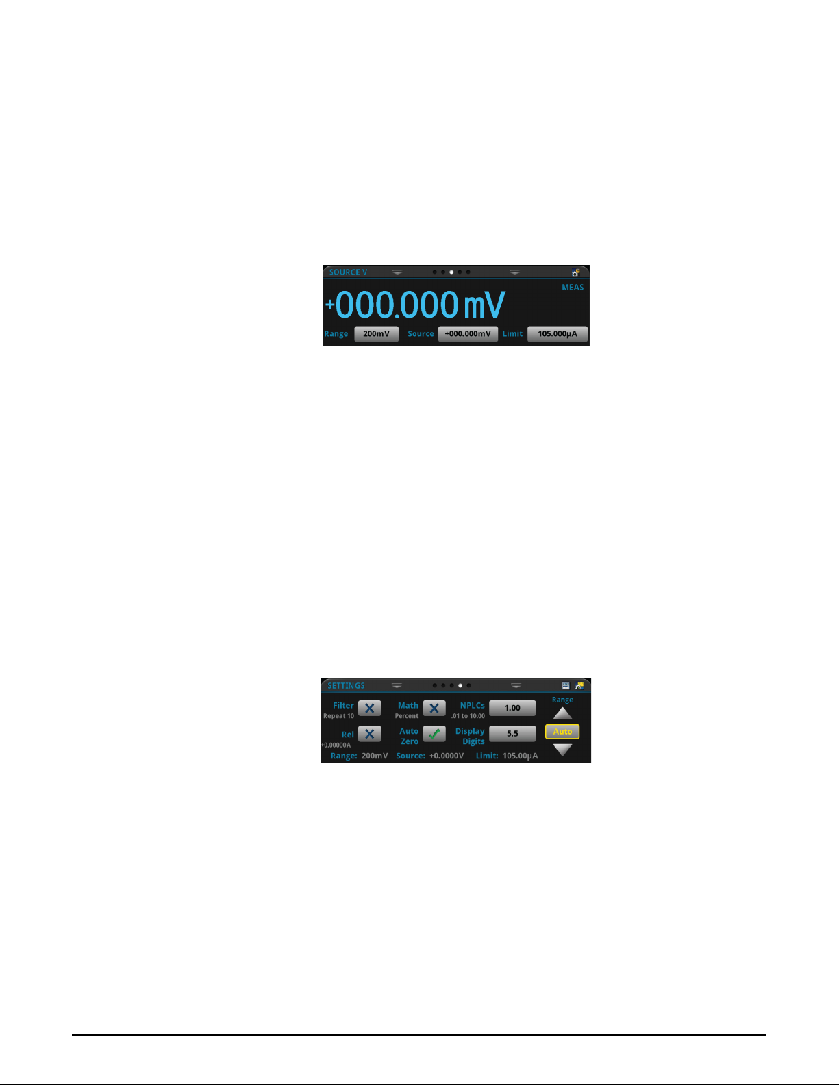
SOURCE swipe screen
The SOURCE swipe screen shows the present value of the source and the set values for source,
source range, and source limit. You can change the set values from the front panel by selecting the
buttons on this screen.
Source function indicators on the right side of t he sc reen signify settings that affect the displayed
source value.
• MEAS: Source readback is on and the value shown is the measured value of the source.
• PROG: Source readback is off and the value shown is the programmed source value. If the
put is off, the displayed source value is replaced with Output Off.
out
Figure 5: SOURCE swipe screen
The icon on the right side of the swipe screen headi ng bar is a shortcut to the full SOURCE
SETTINGS menu.
SETTINGS swipe screen
The SETTINGS swipe screen gives you front-panel access to some instrument settings. It shows you
the present settings and allows you to change, enable, or disable them quickly.
Figure 6: SETTINGS swipe screen
To disable or enable a setting, select the box next to the setting so that it shows an X (disabled) or a
check mark (enabled).
The icons on the right side of the swipe screen heading bar are shortcuts to the CALCULATIONS
SETTINGS and MEASURE SETTINGS menus.
For descriptions of the settings, use the navi gation control to select the button, then press the
HELP key.
2-8 2470-900-01 Rev. A / May 2019
Page 21

Model 2470
panel overview
High Voltage SourceMeter Instrument User's Manual Section 2: Front-
STATISTICS swipe screen
The STATISTICS swipe screen contains informati on about the readings in the active reading buffer.
When the reading buffer is configured to fill cont i nuously and overwrite old data with new data, the
buffer statistics include the data that was overwrit ten. To get statistics that do not include data that
has been overwritten, define a large buffer size that will accommodate the number of readings you
will make. You can use the Clear Active Buffer butto n on this screen to clear the data from the active
reading buffer.
USER swipe screen
If you program custom text, it is displayed on the USE R swipe screen. For example, you can program
the 2470 to show that a test is in process. For details about using remote commands to program the
display, refer to Customizing a message f or the USER swipe screen.
Figure 7: STATISTICS swipe screen
Figure 8: USER swipe screen
GRAPH swipe screen
The GRAPH swipe screen shows a graphical rep resentation of the readings in the presently selected
reading buffer.
Figure 9: GRAPH swipe screen
To view the graph in the full screen and to access gra ph set t i ngs, select the graph icon on the right
side of the swipe screen header. You can also open the full-function Graph screen by pressing the
MENU key and selecting Graph under Views.
For more information about graphing measurem ent s, see "Graphing" in the Model 2470
Reference Manual.
2470-900-01 Rev. A / May 2019 2-9
Page 22
Section
User's Manual
2: Front-panel overview Model 2470 High Voltage SourceMeter Instrument
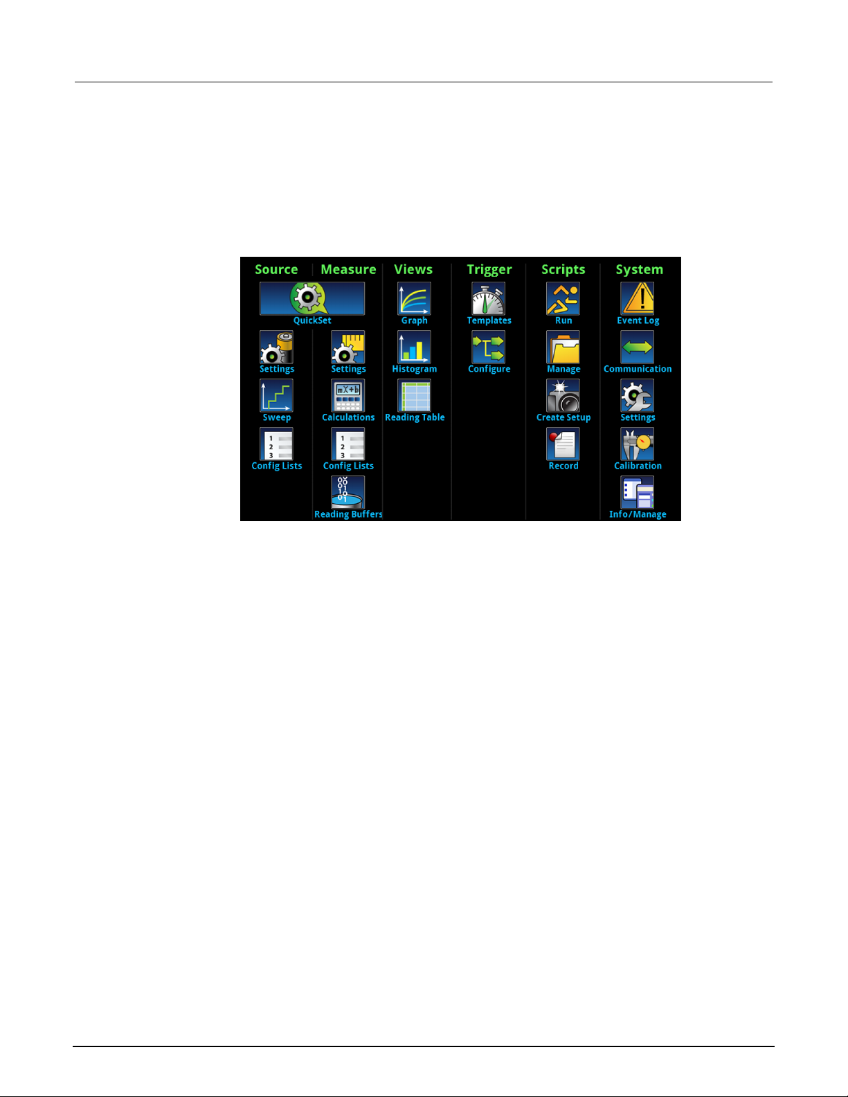
Menu overview
To access the main menu, press the MENU key on the 2470 front panel. The figure below shows the
organization of the main menu.
Figure 10: 2470 main menu
The main menu includes submenus that are labeled in green across the top of the display. Selecting
an option in a submenu opens an interactive screen.
Store measurements on a USB flash drive
If there is measurement data in the buffer, you can copy it from the 2470 to a USB flash drive. The
information is saved in the CSV file format.
To store measurement data:
1. Insert a flash drive into the front-panel USB port.
2. Press the MENU key.
3. In the Measure column, select Reading Buffers.
4. Select the buffer that you want to save.
5. Select Save to USB.
6. Enter a name for the new file.
7. Select the OK button on the displayed keyboard.
8. Select Yes to confirm saving the file.
9. Select OK to close the dialog box.
2-10 2470-900-01 Rev. A / May 2019
Page 23

Model 2470
panel overview
High Voltage SourceMeter Instrument User's Manual Section 2: Front-
Save screen captures to a USB flash drive
You can save a screen capture of the front-panel display to a graphic file. The instrument saves the
graphic file to the USB flash drive in the PNG file format.
To save a screen capture:
1. Insert a USB flash drive in the USB port on the front panel of the instrument.
2. Navigate to the screen you want to capture.
3. Press the HOME and ENTER keys. The instrument displays "Saving screen capture."
4. Release the keys.
2470-900-01 Rev. A / May 2019 2-11
Page 24

Page 25

Determining the command set you will use ............................ 3-15
Using a remote interface
In this section:
Remote communications interfaces ......................................... 3-1
Supported remote interfaces .................................................... 3-1
GPIB communications .............................................................. 3-2
LAN communications ............................................................... 3-4
USB communications ............................................................... 3-7
Using the web interface .......................................................... 3-12
Remote communications interfaces
Section 3
You can choose from one of several communication i nterfaces to send commands to and receive
responses from the 2470.
You can control the 2470 from only one communications interface at a time. The first interface on
which the instrument receives a message take s co ntrol of the instrument. If another interface sends a
message, that interface can take control of t he inst rument. You may need to enter a password to
change the interface, depending on the access mode .
The 2470 automatically detects the type of communications interface (LAN, USB, or GPIB) when you
connect to the respective port on the rear panel of t he inst rument. In most cases, you do not need to
configure anything on the instrument. In addit ion, you do not need to reboot if you change the type of
interface that is connected.
Supported remote interfaces
The 2470 supports the following remote interfaces:
• GPIB: IEEE-488 instrumentation general purpose interface bus
• Ethernet: Local-area-network communications
• USB: Type B USB port
• TSP-Link: A high-speed trigger synchronization and communications bus that test system
builders can use to connect multiple instruments in a master-and-subordinate configuration
For details about TSP-Link, see "TSP-Link System Expansion Interface" in t he M odel 2470
Reference Manual.
Page 26
Section
User's Manual
3: Using a remote interface Model 2470 High Voltage SourceMeter Ins trument
GPIB communications
The 2470 GPIB interface is IEEE Std 488.1 compliant and supports IEEE Std 488.2 common
commands and status model topology.
You can have up to 15 devices connected to a GPIB interface, including the controller. The maximum
cable length is the lesser of either:
• The number of devices multiplied by 2 m (6.5 ft)
• 20 m (65.6 ft)
You may see erratic bus operation if you ignore these limits.
Install the GPIB driver software
Check the documentation for your GPIB controller for information about where to acquire drivers.
Keithley Instruments also recommends that you check the website of the GPIB controller for the latest
version of drivers or software.
It is important that you install the drivers before you connect the hardware. This prevents associatin g
the incorrect driver to the hardware.
Install the GPIB cards in your computer
Refer to the documentation from the GPIB controller vendor for information about installing the GPI B
controllers.
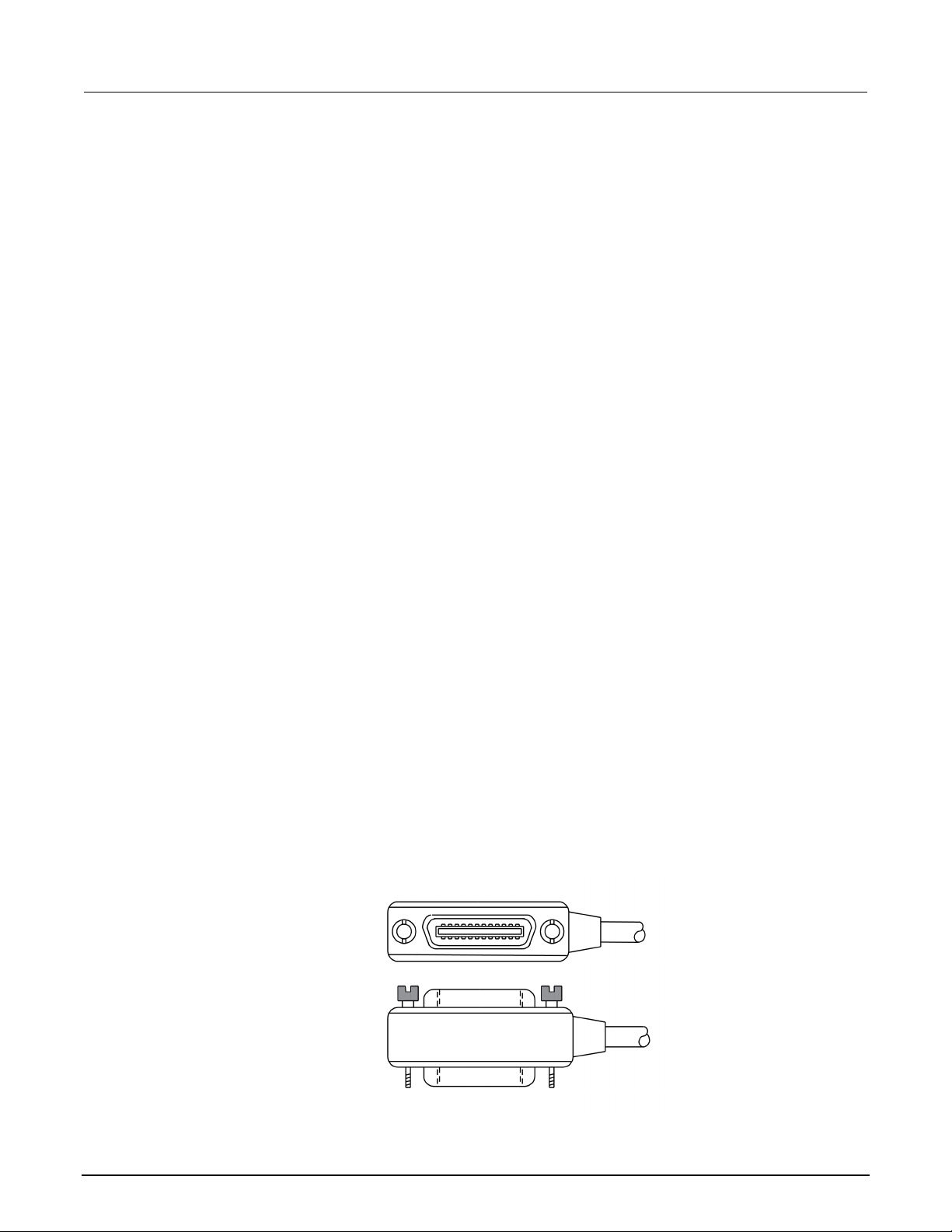
Connect GPIB cables to your instrument
To connect a 2470 to the GPIB interface, use a cable equi pped with standard GPIB connectors, as
shown below.
Figure 11: GPIB connector
3-2 2470-900-01 Rev. A / May 2019
Page 27

Model 2470
Using a remote interface
High Voltage SourceMeter Instrument User's Manual Section 3:
To allow many parallel connections to one instrument, stack the connectors. Each connector has two
screws on it to ensure that connections remain secure. The figure below shows a typical connection
diagram for a test system with multiple instruments.
To avoid possible mechanical damage, stac k no more than three connectors on any one
instrument. To minimize interference caused by electromagnetic radiation, use only shielded
GPIB cables. Contact Keithley Instrumen ts for shielded cables.
Figure 12: IEEE-488 connection example
To connect the GPIB cable to the instrument:
1. Align the cable connector with the connector on the 2470 rear panel.
2. Attach the connector. Tighten the screws securely but do not overtighten them.
3. Connect any additional connectors from other instruments, as required for your a ppl i cation.
4. Make sure that the end of the cable is properly connected to the controller.
2470-900-01 Rev. A / May 2019 3-3
Page 28

Section
User's Manual
3: Using a remote interface Model 2470 High Voltage SourceMeter Ins trument
Set the GPIB address
The default GPIB address is 18. You can set the add ress from 1 to 30 if it is unique in the system.
This address cannot conflict with an addres s t hat is assigned to another instrument or to the GPIB
controller.
GPIB controllers are usually set to 0 or 21. To be safe, do not configure any instrument to have an
address of 21.
The instrument saves the address in nonvolatile memory. It does not change when you send a reset
command or when you turn the power off and on again.
To set the GPIB address from the front panel:
1. Press the MENU key.
2. Select Communication.
3. Select the GPIB tab.
4. Set the GPIB Address.
5. Select OK.
You can also set the GPIB address using remote com m ands. Set the GPIB address with the SCPI
command :SYSTem:GPIB:ADDRess or the TSP command gpib.address.
LAN communications
You can communicate with the instrument using a lo cal area network (LAN).
When you connect using a LAN, you can use a web browser to access the internal web page of the
instrument and change some of the instrument set t i ngs. For more information, see
interface (on page 3-12).
The 2470 is a version 1.4 Core 2011 compliant in st rument that supports TCP/IP and complies with
IEEE Std 802.3 (ethernet LAN). There is one LAN port (located on t he rear panel of the instrument)
that supports full connectivity on a 10 Mbps or 100 M bps network. The 2470 automatically detects the
speed.
Using the web
The 2470 also supports Multicast DNS (mDNS) and DNS Service Discovery (DNS-SD), which are
useful on a LAN with no central administration.
3-4 2470-900-01 Rev. A / May 2019
Page 29

Model 24
Using a remote interface
70 High Voltage SourceMeter Instrument User's Manual Section 3:
Contact your network administrator to confirm your specific network requirements before setting up a
LAN connection.
If you have problems setting up the LAN, refer to LAN t roubles hooti ng sugge stio ns (on page 3-13
Set up LAN communications on the instrument
This section describes how to set up manual or automatic LAN communications on the instrument.
Check communication settings
Before setting up the LAN configuration, you can c heck the communication settings on the instrument
without making any changes.
To check communication settings on the instrument:
1. Press the MENU key.
2. Under System, select Communication. The SYSTEM COMMUNICATIONS window opens.
3. Select LAN to see the settings for that interface.
Set up automatic LAN configuration
If you are connecting to a LAN that has a DHCP server or if you have a direct connection between the
instrument and a host computer, you can use automatic IP address selection.
).
If you select Auto, the instrument attempts to get an IP address from a DHCP server. If this fails, it
reverts to an IP address in the range of 169.254.1.0 through 169.254.254.255.
Both the host computer and the instrument should be set to use automatic LAN configuration.
Though it is possible to have one set to manual configuration, it is more complicated to set up.
To set up automatic IP address selection using the front panel:
1. Press the MENU key.
2. Under System, select Communication.
3. Select the LAN tab.
4. For TCP/IP Mode, select Auto.
5. Select Apply Settings to save your settings.
2470-900-01 Rev. A / May 2019 3-5
Page 30

Section
User's Manual
3: Using a remote interface Model 2470 High Voltage SourceMeter Ins trument
Set up manual LAN configuration
If necessary, you can set the IP address on the instrument manually.
You can also enable or disable the DNS settings and assign a host name to the DNS server.
Contact your corporate information technology (I T ) department to secure a valid IP address for the
instrument when placing the instrument on a corporate network.
The instrument IP address has leading zeros, but the computer IP address cannot.
To set up manual IP address selection on the instrument:
1. Press the MENU key.
2. Under System, select Communication.
3. Select the LAN tab.
4. For TCP/IP Mode, select Manual.
5. Enter the IP Address.
6. Enter the Gateway address.
7. Enter the Subnet mask.
8. Select Apply Settings to save your settings.
Set up LAN communications on the computer
This section describes how to set up the LAN communications on your computer.
Do not change your IP address without consulting your system administrator. If you enter an
incorrect IP address, it can prevent your computer f rom connecting to your corporate network or it
may cause interference with another network ed computer.
Record all network configurations before modif ying any existing network configuration information on
the network interface card. Once the network configuration settings are updated, the previous
information is lost. This may cause a problem reconnecting the host computer to a corporate network,
particularly if DHCP is disabled.
Be sure to return all settings to their original co nfiguration before reconnecting the host computer to a
corporate network. Contact your system admini st rat or for more information.
3-6 2470-900-01 Rev. A / May 2019
Page 31

Model 2470
Using a remote interface
High Voltage SourceMeter Instrument User's Manual Section 3:
Verify the LAN connection on the 2470
Make sure that your 2470 is connected to the netwo rk by confirming that your instrument was
assigned an IP address.
To verify the LAN connection:
1. Press the MENU key.
2. Under System, select Communication.
3. Select the LAN tab.
The green LAN LED on the upper right of the front panel is on when your instrument is connected to
the network.
Use the LXI Discovery Tool
To find the IP address of the 2470, use the LXI Discovery Tool, a utility that is available from the
Resources tab of the LXI Consortium website (lxistandard.org/
).
USB communications
To use the rear-panel USB port, you must have the Vi rt ual Instrument Software Architecture (VISA)
layer on the host computer. See "How to install the Keithley I/O Layer" in the Model 2470 Reference
Manual for more information.
VISA contains a USB-class driver for the USB Test and Measurement Class (USBTMC) protocol that,
once installed, allows the Microsoft Windows operating system to recognize the instrument.
When you connect a USB device that implements the USBTMC or USBTMC-USB488 protocol to the
computer, the VISA driver automatically detects the device. Note that the VISA driver only
automatically recognizes USBTMC and USBTMC-USB488 devices. It does not recognize other USB
devices, such as printers, scanners, and storage devices.
In this section, "USB instruments" refers to devices that implement the USBTMC or
USBTMC-USB488 protocol.
2470-900-01 Rev. A / May 2019 3-7
Page 32

Section
User's Manual
3: Using a remote interface Model 2470 High Voltage SourceMeter Ins trument
Connect a computer to the 2470 using USB
To communicate from a computer to the instrument you need a USB cable with a USB Type B
connector end and a USB type A connector end. Y ou need a separate USB cable for each instrument
you plan to connect to the computer at the same time using the USB interface.
To connect an instrument to a computer using USB:
1. Connect the Type A end of the cable to the computer.
2. Connect the Type B end of the cable to the instrument.
3. Turn on the instrument power. When the computer detects the new USB connection, the Fou
N
ew Hardware Wizard starts.
4. If the "Can Windows connect to Windows Update to search for software?" dialog box opens,
select No, and then select Next.
5. On the "USB Test and Measurement device" dialog box, select Next, and then select Finish.
Communicate with the instrument
For the instrument to communicate with the USB device, you must use NI-VISATM. VISA requires a
resource string in the following format to connect to the correct USB instrument:
USB0::0x05e6::0x2470::[serial number]::INSTR
Where:
• 0x05e6: The Keithley vendor ID
• 0x2470: The instrument model number
• [serial number]: The serial number of the instrument (the serial number is also on the rear
panel)
• INSTR: Use the USBTMC protocol
nd
To determine these parameters, you can run the Keithley Configuration Panel, which automatically
detects all instruments connected to the computer.
If you installed the Keithley I/O Layer, you can access the Keithley Configuration Panel through the
Microsoft
3-8 2470-900-01 Rev. A / May 2019
®
Windows® Start menu.
Page 33

Model 2470
Using a remote interface
High Voltage SourceMeter Instrument User's Manual Section 3:
To use the Keithley Configuration Panel to determine the VISA resource string:
1. Click Start > Keithley Instruments > Keithley Configuration Panel. The Select Operatio
dialog box is displayed.
Figure 13: Select Operation dialog box
n
2. Select Add.
3. Select Next. The Select Communication Bus dialog box is displayed.
Figure 14: Select Communication Bus dialog box
2470-900-01 Rev. A / May 2019 3-9
Page 34

Section
User's Manual
3: Using a remote interface Model 2470 High Voltage SourceMeter Ins trument
4. Select USB.
5. Click Next. The Select Instrument Driver dialog box is displayed.
Figure 15: Select Instrument Driver dialog box
6. Select Auto-detect Instrument Driver - Model.
7. Click Next. The Configure USB Instrument dialog box is displayed with the detected instrument
VISA resource string visible.
8. Click Next. The Name Virtual Instrument dialog box is displayed.
Figure 16: Name Virtual Instrument dialog box
3-10 2470-900-01 Rev. A / May 2019
Page 35

Model 2470
Using a remote interface
High Voltage SourceMeter Instrument User's Manual Section 3:
9. In the Virtual Instrument Name box, enter a name that you want to use to refer to the instrument.
10. Select Finish.
11. Select Cancel to close the Wizard.
12. Save the configuration. From the Keithley Configuration Panel, select File > Save.
Verify the instrument through the Keithley Communicator:
1. Click Start > Keithley Instruments > Keithley Communicator.
2. Select File > Open Instrument to open the instrument you just named.
Figure 17: Keithley Communicator Open an Instrument
3. Click OK.
4. Send a command to the instrument and see if it responds.
If you have a full version of NI-VISA on your system, you can run NI-MAX or the VISA Interactive
Control utility. See the National Instruments documentation for information.
2470-900-01 Rev. A / May 2019 3-11
Page 36

Section
User's Manual
3: Using a remote interface Model 2470 High Voltage SourceMeter Ins trument
Using the web interface
The 2470 web interface allows you to make settings and control your instrument through a web page.
The web page includes:
• Instrument status.
• The instrument model, serial number, firmware revision, and the last LXI m ess age.
• An ID button to help you locate the instrument.
• A virtual front panel and command interface that you can use to control the instrument.
• Ability to download data from specific reading buffers into a CSV file.
• Administrative options and LXI information.
The instrument web page resides in the firmware of the instrument. Changes you make through the
web interface are immediately made in the inst rum ent.
When the LAN and instrument establish a connection, you can open the web page for the instrument.
To access the web interface:
1. Open a web browser on the host computer.
2. Enter the IP address of the instrument in the address box of the web browser. For exampl e, if t
instrument IP address is 192.168.1.101, enter 192.168.1.101 in the browser address box.
3. Press Enter on the computer keyboard to open the instrument web page.
4. If prompted, enter a user name and password. The default is admin for both.
If the web page does not open in the browser, see LAN troubleshooting suggestions (on page 3-13).
To find the IP Address of the instrument, press the Comm unications indicator in the upper left corner
of the home screen.
he
3-12 2470-900-01 Rev. A / May 2019
Page 37

Model 2470
Using a remote interface
High Voltage SourceMeter Instrument User's Manual Section 3:
LAN troubleshooting suggestions
If you are unable to connect to the web interface of the instrument, check the following items:
• The network cable is in the LAN port on the rear panel of the instrument, not one of the
SP-Link
T
• The network cable is in the correct port on the computer. The LAN port of a laptop may be
di
sabled when the laptop is in a docking station.
• The setup procedure used the configuration information for the correct ethernet card.
• The network card of the computer is enabled.
• The IP address of the instrument is compatible with the IP address on the computer.
• The subnet mask address of the instrument is the same as the subnet mask address of the
c
omputer.
You can also try restarting the computer and the instrument.
®
ports.
To restart the instrument:
1. Turn the power to the instrument off, and then on.
2. Wait at least 60 seconds for the network configuration to be completed.
To set up LAN communications:
1. Press the MENU key.
2. Under System, select Communication.
3. Select the LAN tab.
4. Verify the settings.
If the above actions do not correct the problem, cont act your system administrator.
2470-900-01 Rev. A / May 2019 3-13
Page 38

Section
User's Manual
3: Using a remote interface Model 2470 High Voltage SourceMeter I ns trument
Web interface Home page
Figure 18: Model 2470 web interface Home page
The Home page of the instrument provides informati on about the instrument. It includes:
• The instrument model number, manufacturer, serial number, and firmware rev i sion number.
• The TCP Raw Socket number and Telnet Port number.
• The last LXI message. The history link opens the LXI Home page.
• The ID button, which allows you to identify the instrument. Refer to Identify t he instrument (on
page 3-14).
Identify the instrument
If you have a bank of instruments, you can select the ID button to determine which one you are
communicating with.
Before trying to identify the instrument, make sure you have a remote connection to the instrument.
To identify the instrument:
1. On the Home page, select the ID button. The button turns green and the LAN status indicator
the instrument blinks.
2. Select the ID button again to return the button to its original color and return the LAN status
indicator to steady on.
on
3-14 2470-900-01 Rev. A / May 2019
Page 39

Model 2470
Using a remote interface
High Voltage SourceMeter Instrument User's Manual Section 3:
Review events in the event log
The event log records all LXI events that the instrum ent generates and receives. The log includes the
following information:
• The EventID column, which shows the identifier of the event that generated the event m essage.
• The System Timestamp column, which displays the seconds and nanoseconds when t he event
occurred.
• The Data column, which displays the text of the event message.
To clear the event log and update the information on the screen, select the Refresh button.
Determining the command set you will use
You can control the 2470 with command sets that are based on the SCPI or Test Script Processor
®
(TSP
) programming languages. You can change the command set that you use with the 2470. The
remote command sets that are available include:
• SCPI: An instrument-specific language built on the SCPI standard.
• TSP: A scripting programming language that contains instrument-specific control comm and s that
can be executed from a stand-alone instrument. You can use TSP to send individual commands
or use it to combine commands into scripts.
If you change the command set, reboot the instrument.
You cannot combine the command sets.
As delivered from Keithley Instruments, the 2470 is set to work with the SCPI command set.
To set the command set from the front panel:
1. Press the MENU key.
2. Under System, select Settings.
3. Select the appropriate Command Set.
You are prompted to confirm the change to the command set and reboot.
2470-900-01 Rev. A / May 2019 3-15
Page 40

Section
User's Manual
3: Using a remote interface Model 2470 High Voltage SourceMeter Ins trument
To verify which command set is selected from a remote interface:
Send the command:
*LANG?
To change to the SCPI command set from a remote interface:
Send the command:
*LANG SCPI
Reboot the instrument.
To change to the TSP command set from a remote interf ace:
Send the command:
*LANG TSP
Reboot the instrument.
3-16 2470-900-01 Rev. A / May 2019
Page 41

Make front-panel measurements .............................................. 4-3
In this section:
Introduction .............................................................................. 4-1
Equipment required for this application .................................... 4-2
Device connections .................................................................. 4-2
Introduction
You can use the 2470 to source voltage or current an d m ake measurements from the front panel.
Section 4
Making basic front-panel measurements
Make sure you select functions before you make changes to other instrument settings. The options
that you have for settings depend on the function s t hat are active when you make the changes. If
you make a change that is not compatible with the active functions, you may get unexpected results
or you may receive an event message. Also note that when you select a different function, the
instrument clears the buffer. The applications in this manual illustrate the order in which you should
perform operations for best results.
In this application, you make measurements on a 10 kΩ resistor by sourcing voltage and measuring
current. You can make similar measurement s on any two-terminal device under test (DUT) if
appropriate source values are used.
Some of the methods you can use to set up the 2470 t o m ake measurements from the front panel
include:
• Use Quicksets. Press the QUICKSET key to open a menu of preconfigured setups, i ncluding
voltmeter, ammeter, ohmmeter, and power supply setups. It al so allows you to choose test
functions and adjust performance for better re solut i on or speed.
• Select source and measure functions. Press the FUNCTION key to select from a list of source
and measure functions.
• Use menu options. Press the MENU key to open a menu of options.
After selecting your source and measure functions, select buttons on the 2470 Home screen and
Settings swipe screens to change the settings.
You will use a combination of these methods to set up the measurement for this application.
Page 42

Section
User's Manual
4: Making basic front-panel measurements Model 2470 High Voltage SourceMeter Instrument
Equipment required for this application
Equipment required for this application:
• 2470 High Voltage SourceMeter Instrument
• Two insulated banana cables; you can use the set that is provided with the 2470, the Kei thley
Instruments Model 8608 High-Performance Clip Lead Set
• One 10 kΩ resistor to test
Device connections
Turn the power to the instrument off before attaching connections to the 2470.
Connect the 2470 to the resistor in a 2-wire (local sense) configuration. In this configuration, the
device is connected between the FORCE HI and FORCE LO terminals.
The physical connections to the front panel are sh own in the following figure.
Figure 19: 2470 2-wire front-panel connections
4-2 2470-900-01 Rev. A / May 2019
Page 43

Model 2470
panel measurements
High Voltage SourceMeter Instrument User's Manual Section 4: Making basic front-
Make front-panel measurements
For this application, you will:
• Select the source and measure functions
• Select the source range
• Set the source value
• Set the source limit
• Select the measurement range
• Turn on the source output
• Observe the readings on the display
• Turn off the source output
How to make front-panel measurements
To make a measurement from the front panel:
1. Press the POWER switch on the front panel to turn on the instrument or cycle power if t
instrument is already on.
2. On the front panel, press the FUNCTION key to verify the source and measure function.
3. Under Source Voltage and Measure, select Current.
4. Select the source range. On the home screen, under SOURCE V, select Range.
5. Select 20 V.
6. Select Source.
7. Enter 10 V and select OK.
8. Select Limit.
9. Enter 10 mA and select OK.
10. In the MEASURE area of the home screen, select Range.
11. Select Auto.
12. Turn on the output by pressing the OUTPUT ON/OFF switch. The OUTPUT indicator light
turns on.
13. Observe the readings on the display. For the 10 kΩ resistor, typical display values are:
1.00000 mA
+9.99700 V
he
14. When measurements are complete, turn the output of f by pressing the OUTPUT ON/OFF switch.
The OUTPUT indicator light turns off.
2470-900-01 Rev. A / May 2019 4-3
Page 44

Page 45

Measuring insulation resistance ............................................... 5-9
In this section:
Introduction .............................................................................. 5-1
Equipment required .................................................................. 5-2
Set up remote communications ................................................ 5-2
Device connections .................................................................. 5-2
Measuring leakage current ....................................................... 5-4
Introduction
Tests to measure the leakage current or insulat ion resistance of a device are very similar. In both
cases, you can apply a fixed bias voltage and measure the resulting current. Depending on the
device under test, the measured current is t ypically very small, usually less than 10 nA.
Section 5
Leakage current and insulation resistance
This application consists of two examples that dem onstrate:
• How to use the 2470 to perform leakage current mea surements on a capacitor.
• How to use the 2470 to measure insulation resistance between the two conductors of a
coaxial cable.
The leakage current application applies a voltage for a specified period. This soak period allows time
for the device to charge so that you can make a settled-current measurement. In this application, the
resulting current is measured the entire time the device is biased. In other cases, only one reading is
required and may be made at the end of the soak period. The application ends by applying 0 volts to
discharge the device. The results are returned i n uni ts of amperes.
The insulation-resistance application applies voltage and m akes a specified number of readings with
a set delay between each reading. This allows the measurement to settle, but it is easier to specify
exactly how many readings are made. Insulation ty picall y settles much faster than a capacitor device.
The results are returned in units of ohms.
The following topics describe how to do these applications from the front panel. They also show how
®
to do them using a remote interface with SCPI and Test Script Processor (TSP
) commands.
Page 46

Section
User's Manual
5: Leakage current and insulation resistance Model 2470 High Voltage SourceMeter Ins trument
Equipment required
• One 2470 High Voltage SourceMeter Instrument
• Two TRX-1100V-X 3-Slot High-Voltage Low-Noise Triaxial Cables (available from Keithley
Instruments)
• One high-voltage capacitor for the leakage current application
• One coaxial cable or other device for the insulation resistance application
• One ethernet, GPIB, or USB cable for the SCPI and TSP remote command examples
Set up remote communications
You can run this application from the front panel or any of the supported communication interfaces f or
the instrument (GPIB, USB, or ethernet).
The following figure shows the rear-panel connection locations for the remote communication
interfaces. For additional information about set ting up remote communications, see
communications interfaces (on page 3-1).
Remote
Figure 20: Model 2470 remote interface connections
Device connections
Depending on the device under test (DUT), the current measurement is typically very small, usually
<10 nA. For any device, measuring leakage c urrent and insulation resistance involves measuring v ery
small values. To get more accurate readings, connect the DUT to the 2470 rear panel with low-noise
triaxial cables.
Connect the DUT between the FORCE HI and FORCE LO terminals of the 2470.
The following figure shows schematic diagrams. O ne shows measuring the leakage current of a
capacitor. The other shows measuring the ins ul ator resistance between two conductors of a
coaxial cable.
5-2 2470-900-01 Rev. A / May 2019
Page 47

Model 2470
Leakage current and insulation resistance
High Voltage SourceMeter Instrument User's Manual Section 5:
Figure 21: Capacitor leakage and insulation resistance test connection schematics
The following figures show the rear-terminal co nnections to the device under test (DUT) for these
applications. If capacitor leakage measurements are noisy, you may need to use the high
capacitance mode or add a low leakage forward-biased diode in series with the capacitor.
Figure 22: Rear-panel connections for the leakage current test
Figure 23: Rear-panel connections insulation resistance test
2470-900-01 Rev. A / May 2019 5-3
Page 48

Section
User's Manual
5: Leakage current and insulation resistance Model 2470 High Voltage SourceMeter Instrument
Measuring leakage current
The following application demonstrates how to use the 2470 to measure the leakage current of a
high-voltage 10 µF capacitor by sourcing a voltage and measuring the resulting current using the front
panel or over the remote interface. The remote interface examples show SCPI commands and TSP
commands.
This application sets the 2470 to source 300 V and measure the resulting leakage current as a
function of time. The instrument makes current m easurements for a specific period.
For this test, you will:
• Reset the instrument
• Set the instrument to read the rear terminals
• Select the source voltage function and measure current function
• Set the magnitude of the voltage source
• Turn on autoranging
• Set the measure delay
• Use the DurationLoop trigger model template to make readings for a specified perio d
• Turn on the source output
• Take readings for a specified period
• Turn off the source output
When you use the 2470 to measure small current values, ensure that the device under test is
electrostatically shielded. If the capacitor rat i ng is greater than 20 nF, enable the high capacitance
mode for best results.
For more information about making optimize d capacitor leakage measurements and minimizing
noisy measurements, see the Keithley Instrum ents Low Level Measurements Handbook, available
on the Keithley Instruments website (tek.com/keithley
).
5-4 2470-900-01 Rev. A / May 2019
Page 49

Model 2470
on resistance
High Voltage SourceMeter Instrument User's Manual Section 5: Leakage current and insulati
Set up the leakage current application using the front panel
To set up the application from the front panel:
1. Use the test leads to make the connection from the capacitor to the rear panel of the 2470, as
described in Device connections (on page 5-2
2. Reset the 2470.
a. Press the MENU key.
b. Under System, select Info/Manage.
c. Select System Reset, and then select OK.
3. Press the TERMINALS FRONT/REAR switch to set the instrument to use the rear-panel
terminals (R is displayed to the left of the switch).
4. Press the HOME key.
5. Press the FUNCTION key.
6. Under Source Voltage and Measure, select Current.
7. Select the button next to Source (at the bottom of the screen).
).
8. Enter 300 V and select OK.
9. Select the button next to Limit (at the bottom of the screen).
10. Enter 10 mA and select OK.
11. Press the MENU key.
12. Under Trigger, select Templates.
13. Set Templates to DurationLoop.
14. Set Duration to a soak time of 30s.
15. Set the delay to 0.2s. After each reading, a delay of 0. 2 s occurs; each reading is not 0.2 s apart.
16. Press the HOME key to return to the Home screen.
17. Press the TRIGGER key to turn on the output and make measurem ents. The output is turned off
when the measurements are complete.
2470-900-01 Rev. A / May 2019 5-5
Page 50

Section
User's Manual
5: Leakage current and insulation resistance Model 2470 High Voltage SourceMeter Ins trument
View the measurements on the front-panel graph
To view the leakage current measurements on the front-panel graph:
1. Press the MENU ke
2. Under Views, select Graph.
3. Select the Scale tab.
4. Under Y-Axis, next to Scale Format, select Log.
5. Under X-Axis, next to Method, select All.
6. Select the Graph tab to view the graph.
The following figure shows the front-panel gra ph f or this application.
y.
Figure 24: Front panel graph of leakage current measurement
5-6 2470-900-01 Rev. A / May 2019
Page 51

Model 2470
Leakage current and insulation resistance
*RST
Turn off the output.
High Voltage SourceMeter Instrument User's Manual Section 5:
Set up the leakage current application using SCPI commands
The following SCPI code performs a capacitor leakage measurement by sourcing 300 V and
measuring the resulting leakage current. T he DurationLoop trigger model template applies the voltage
for 30 seconds and makes measurements at 200 ms intervals. After the duration time, the capacitor is
discharged at 0 V and the output is turned off.
Send the following commands for this example application:
Command Description
:SOUR:FUNC VOLT
:SOUR:VOLT 300
:SOUR:VOLT:ILIMIT 0.01
:SENSE:FUNC "CURR"
:ROUT:TERM REAR
:CURR:RANG:AUTO ON
:SENSE:CURR:NPLC 1
:TRIG:LOAD "DurationLoop", 30, 0.2
Reset the 2470.
Set to source voltage.
Set the source voltage to 300 V.
Set the current limit to 10 mA.
Set the instrument to measure cur rent.
Set to use rear-panel terminals.
Set the current range to autorange.
:INIT
*WAI
:TRAC:ACT? "defbuffer1"
:TRAC:DATA? 1, 30, "defbuffer1", READ, REL
:SOUR:VOLT 0
:OUTP ON
:OUTP OFF
Set the number of power line cycles to 1.
Load the DurationLoop trigger model to run
for 30 s with 200 ms delays.
Start the trigger model.
Wait for the measurement to finish.
Query the number of readings in
defbuffer1 and return the readings and
time. 30 is the queried number of readings.
Discharge the capacitor to 0 V.
Turn on the output.
Set up the leakage current application using TSP commands
The following TSP code is designed to be run from Keithley Instruments Test Script Builder (TSB).
TSB is a software tool that is available from tek.com/keithley
code and develop scripts for TSP-enabled instruments. Information about how to use TSB is in the
online help for TSB and in the “Introduction to TSP operat i on” section of the Model 2470 Reference
Manual.
. You can install and use TSB to write
2470-900-01 Rev. A / May 2019 5-7
By default, the 2470 uses the SCPI command set. You must select the TSP command set before
sending TSP commands to the instrument.
Page 52

Section
User's Manual
5: Leakage current and insulation resistance Model 2470 High Voltage SourceMeter Ins trument
To enable TSP commands:
1. Press the MENU key.
2. Under System, select Settings.
3. Set the Command Set to TSP.
4. At the prompt to reboot, select Yes.
The following TSP code performs a capacitor leakage measurement by sourcing 300 V and
measuring the resulting leakage current. T he DurationLoop trigger model template applies the voltage
for 30 seconds and makes measurements at 200 ms intervals. After the duration time, the capacitor is
discharged at 0 V and the output is turned off.
After the code is executed, the measurement results are displayed in the Instrument Console of Test
Script Builder. From the Instrument Console, y ou can copy the data into a spreadsheet for graphing.
Send the following commands for this example application:
-- Reset the instrument, which also clears the buffer.
reset()
-- Set up the source function.
smu.source.func = smu.FUNC_DC_VOLTAGE
smu.source.ilimit.level = 10e-3
smu.source.level = 300
-- Set up measure function.
smu.measure.func = smu.FUNC_DC_CURRENT
smu.terminals = smu.TERMINALS_REAR
smu.measure.autorange = smu.ON
smu.measure.nplc = 1
-- Turn on the output and initiate readings.
trigger.model.load("DurationLoop", 30, 0.2)
trigger.model.initiate()
-- Wait for the trigger model to complete.
waitcomplete()
-- Parse index and data into three columns.
print("Rdg #,", "Time (s),", "Current (A)")
for i = 1, defbuffer1.n do
print(i, defbuffer1.relativetimestamps[i], defbuffer1[i])
end
-- Discharge the capacitor to 0 V and turn off the output.
smu.source.level = 0
smu.source.output = smu.ON
delay(2)
smu.source.output = smu.OFF
5-8 2470-900-01 Rev. A / May 2019
Page 53

Model 2470
Leakage current and insulation resistance
High Voltage SourceMeter Instrument User's Manual Section 5:
The graph in the following figure shows the result s of this application. Notice the exponential current
response of the capacitor as it charges up to 300 V over time.
Figure 25: Leakage current test results
Measuring insulation resistance
The following application demonstrates how to use the 2470 to measure insulator resistance. The
application shows how to use the front-panel inte rf ace, the remote interface using the SCPI command
set, and the remote interface using the Test Script P rocessor (TSP
You typically make insulation resistance m easurements between traces on a printed circuit board and
between conductors in cables and connectors.
This application sets the 2470 to source 700 V and makes 10 resistance readings with a 100 ms
interval time. Once the measurements are made, t he output is turned off.
For this test, you will:
• Reset the instrument
• Set the instrument to read the rear terminals
• Select the source voltage function and measure resistance function
• Set the magnitude of the voltage source output
• Turn on autoranging
• Use the Simple Loop trigger model template to set the numbers of readings and interval time
• Make readings
®
) command set.
2470-900-01 Rev. A / May 2019 5-9
Page 54

Section
User's Manual
5: Leakage current and insulation resistance Model 2470 High Voltage SourceMeter Ins trument
Set up the insulation resistance application using the front panel
To set up the application from the front panel:
1. Connect the device under test (DUT) to the rear panel of the 2470, as described in
connections (on page 5-2).
2. Reset the 2470.
a. Press the MENU key.
b. Under System, select Info/Manage.
c. Select System Reset, and then select OK.
3. Press the TERMINALS FRONT/REAR switch to set the instrument to use the rear-panel
terminals (R is displayed to the left of the switch).
4. Press the HOME key.
5. Press the FUNCTION key.
6. Under Source Voltage and Measure, select Resistance.
7. Select the button next to Source (at the bottom of the screen).
8. Enter 700 V and select OK.
9. Press the MENU key.
10. Under Trigger, select Templates.
11. Set Templates to SimpleLoop.
12. Set Count to 10.
Device
13. Set Delay to 0.1 seconds.
14. Press the HOME key.
15. Press the OUTPUT ON/OFF switch to enable the output.
16. Press the TRIGGER key to begin taking readings. The resistan ce measurements appear in the
m
easure area (top half) of the Home screen.
17. Press the OUTPUT ON/OFF switch to turn off the output when you are done maki
easurements.
m
ng
5-10 2470-900-01 Rev. A / May 2019
Page 55

Model 2470
Leakage current and insulation resistance
High Voltage SourceMeter Instrument User's Manual Section 5:
Viewing the measurements on the front-panel graph
To view the insulation resistance measurem en ts on the front-panel graph:
1. Press the MENU ke
2. Under Views, select Graph.
The following figure shows the front-panel graph f or this application.
y.
Figure 26: Insulation resistance graph
2470-900-01 Rev. A / May 2019 5-11
Page 56

Section
User's Manual
*RST
Turn the output off.
5: Leakage current and insulation resistance Model 2470 High Voltage SourceMeter Ins trument
Set up the application using SCPI commands
The following SCPI commands make insulatio n resistance measurements by sourcing 700 V and
measuring the resistance. The Simple Loop trigger model template is used to make
10 measurements at 100 ms intervals.
Send the following commands for this example application:
Command Description
:ROUT:TERM REAR
:SOUR:FUNC VOLT
:SOUR:VOLT 700
:SOUR:VOLT:ILIM 0.01
:SENS:FUNC "CURR"
:SENS:CURR:RANG:AUTO ON
:SENSE:CURR:UNIT OHM
:TRIG:LOAD "SimpleLoop", 10, 0.1
:OUTP ON
:INIT
*WAI
:TRAC:DATA? 1, 10, "defbuffer1", READ, REL
:OUTP OFF
Reset the 2470.
Select the rear-panel terminals f or the
measurement.
Set to source voltage.
Output 700 V.
Set a 10 mA source limit.
Set the instrument to measure cur rent.
Set the current range to autorange.
Set the instrument to measure res istance.
Use the Simple Loop trigger model to make 10
measurements at 100 ms intervals.
Turn the output on.
Initiate readings.
Wait for the measurement to finish.
Read the resistance and time values from
defbuffer1.
5-12 2470-900-01 Rev. A / May 2019
Page 57

Model 2470
Leakage current and insulation resistance
High Voltage SourceMeter Instrument User's Manual Section 5:
Set up the application using TSP commands
The following TSP code is designed to be run from Keithley Instruments Test Script Builder (TSB).
TSB is a software tool that is available from tek.com/keithley
code and develop scripts for TSP-enabled instruments. Information about how to use TSB is in the
online help for TSB and in the “Introduction to TSP operat i on” section of the Model 2470
Reference Manual.
By default, the 2470 uses the SCPI command set. You must select the TSP command set before
sending TSP commands to the instrument.
To enable TSP commands:
1. Press the MENU key.
2. Under System, select Settings.
3. Set the Command Set to TSP.
4. At the prompt to reboot, select Yes.
The following TSP commands make insulation resistance measurements by sourcing 700 V and
measuring the resistance. The Simple Loop trigger model template is used to make
10 measurements at 100 ms intervals. After the code i s ex ecuted, the measurement results are
displayed in the Instrument Console of Test Script B ui l der.
. You can install and use TSB to write
2470-900-01 Rev. A / May 2019 5-13
Page 58

Section
User's Manual
5: Leakage current and insulation resistance Model 2470 High Voltage SourceMeter Instrument
Send the following commands for this example application:
--Reset the instrument
reset()
--Set up the source function.
smu.source.func = smu.FUNC_DC_VOLTAGE
smu.source.ilimit.level = 1e-3
smu.source.level = 700
--Set up the measure function
smu.measure.func = smu.FUNC_DC_CURRENT
smu.measure.unit = smu.UNIT_OHM
smu.terminals = smu.TERMINALS_REAR
smu.measure.autorange = smu.ON
smu.measure.nplc = 1
-- Turn on the source output and make readings.
trigger.model.load("SimpleLoop", 10, 0.1)
smu.source.output = smu.ON
trigger.model.initiate()
-- Wait for the measurements to complete.
waitcomplete()
-- Parse index and the data into three columns.
print("Rdg #,", "Time (s),", "Resistance (Ohm)")
for i = 1, defbuffer1.n do
print(i, defbuffer1.relativetimestamps[i], defbuffer1[i])
end
--Turn off the output.
smu.source.output = smu.OFF
The graph in the following figure demonstrates what the plotted results might look like.
Figure 27: Insulation resistance test results
5-14 2470-900-01 Rev. A / May 2019
Page 59

Remote control of FET testing using TSP commands ............ 6-13
In this section:
Introduction .............................................................................. 6-1
Equipment required .................................................................. 6-2
Set up remote communications ................................................ 6-2
Set up external hardware triggers ............................................ 6-3
Device connections .................................................................. 6-5
Remote control of FET testing using SCPI commands ............ 6-8
Introduction
Section 6
Measure I-V characteristics of FETs
This example application uses one or two 2470 instruments to perform I-V characterization of
field-effect transistors (FETs). The high-voltage capa bilities and extremely sensitive current
measurement ranges of the 2470 make it especially suited to wide band-gap semiconductor devices.
The FET for these examples could be a traditional silicon-based MOSFET or gallium nitride (GaN) or
silicon carbide (SiC) based.
This application consists of examples that dem onstrate:
• How to use a 2470 to perform a drain leakage current measurement on a FET
• How to use two 2470s to find the subthreshold swin g of a FET
• How to use two 2470s to perform a drain family of curves (V
Determining the I-V parameters of FETs helps you ensure that they function properly in their intended
applications and that they meet specificat ions. T here are many I-V tests that you can perform with the
2470, including drain or gate leakage, breakdown voltage, threshold voltage, subthreshold swing, and
drain current. The number of 2470 instruments required for testing depends on the number of FET
terminals that must be biased, swept, and measured.
) on a three-terminal FET
DS-ID
Page 60

Section
User's Manual
6: Measure I-V characteristics of FETs Model 2470 High Voltage SourceMeter Ins trument
The SCPI and TSP examples differ in this application. The TSP version uses Keithley Instruments
TSP-Link
builders can use to connect multiple instruments in a master and subordinate configuration. Once
connected, all the instruments that are equipp ed wit h TSP-Link in a system can be programmed and
operated under the control of the master instrument or instruments. This allows the instruments to
run tests more quickly because they can be decoupled from frequent computer interaction. TSP-Link
is not available when the SCPI command set is select ed.
®
, which is a high-speed trigger synchronizat ion and communication bus that test system
Equipment required
• Two 2470 High Voltage SourceMeter Instruments
• Four TRX-1100V-X 3-Slot High-Voltage Low-Noise Triaxial Cables (available from Keithley
Instruments)
• A metal-shielded test fixture or probe station with female triaxial connectors
• One high power or wide band-gap three-terminal FET
• One ethernet, GPIB, or USB cable for the TSP remote command examples
• One cross-over ethernet cable for TSP-Link connections between the two 2470s (one is included
w
ith each 2470)
Set up remote communications
This application is configured to run remotel y. You can run this application from any of the supported
communication interfaces for the instru m ent (GPIB, USB, or ethernet).
The following figure shows the rear-panel connection locations for the remote communication
interfaces.
Figure 28: Model 2470 remote interface connections
6-2 2470-900-01 Rev. A / May 2019
Page 61

Model 2470
V characteristics of FETs
High Voltage SourceMeter Instrument User's Manual Section 6: Measure I-
Set up external hardware triggers
To enable synchronization between the two 2470 i nstruments for stepping and sweeping voltages,
connect the external triggers of each instrument to the other. The cabling you use depends on which
2470 programming command set you choose to control the test.
Connections for the SCPI command set
If you are using the SCPI command set, connect a D B-9 male-to-male cable between the digital I/O
connectors on the back of each of the instruments, as shown in the figure below.
For more detailed information about the digital I/O connector pins, see "Digital I/O" in the 2470
Reference Manual.
Figure 29: GPIB and DB-9 connections for the SCPI programming example
The figure above also shows the communication cable connections if you are using the GPIB remote
communication interface. GPIB cable #1 con nects the GPIB port on the computer (controller) to t he
IEEE-488 connector on the rear panel of 2470 #1. GPIB cable #2 connects the IEEE-488 connector s
of the two 2470s.
Each 2470 must have a different GPIB address. You can set this up using the front panel. For details,
see Set the GPIB address (on page 3-4
2470-900-01 Rev. A / May 2019 6-3
).
Page 62

Section
User's Manual
6: Measure I-V characteristics of FETs Model 2470 High Voltage So urceMeter Instrument
If you are using USB cables to connect the computer and 2470 instruments, each instrument must be
connected to the computer with a separate USB cable.
If you are using ethernet connections to connect t he computer and 2470 instruments, the instruments
and computer must be connected using an ethernet switch or hub.
Connections for the TSP command set
If you use the Test Script Processor (TSP®) command set for remote programming, use a RJ -45 LAN
crossover cable to connect the TSP-Link ports on the rear panels of the 2470 instruments (see figure
below). For more information about using TSP-Link, see "TSP-Link System Expansion Interface" in
the 2470 Reference Manual.
Figure 30: TSP-Link connections
For GPIB communication from the computer to t he 2470 instruments, you only need one cable from
the GPIB interface to one of the 2470 IEEE-488 interfaces (2470 #1 in the figure above).
Set the TSP-Link node of 2470 #1 to node 1 and the TSP-Link node of 2470 #2 to node 2.
6-4 2470-900-01 Rev. A / May 2019
Page 63

Model 2470
FETs
High Voltage SourceMeter Instrument User's Manual Section 6: Measure I-V characteristics of
To set the 2470 TSP-Link nodes from the front panel:
1. Press the MENU key.
2. Under System, select Communication. The SYSTEM COMMUNICATION window opens.
3. On the TSP-Link tab, set Node to the node number of this instrument and select OK.
4. Select Initialize.
5. Press the HOME key to return to the Home screen.
Repeat these steps for each 2470 instrument in your TSP-Link network.
Device connections
Device connections vary depending on the test y ou will perform. Since these applications typically
involve measuring very low currents, it is recom mended that you use the triaxial connections on the
rear-panel of the 2470 with low-noise triaxial cables. Triaxial cable s pr ovide the lowest noise possible
when measuring low currents.
Drain leakage current measurement device connections
A drain leakage current measurement on a FET requires only one 2470. For this measurement, the
gate-source potential must be 0 V, so the gate and source connection pins are shorted together. The
SMU is connected between the drain and source to apply a bias voltage.
To change this measurement to a gate leakage cur rent measurement, you can short the drain and
source together and connect the 2470 between the g ate and source to apply a bias voltage.
The following figure shows the setup for a drain lea kage current measurement.
2470-900-01 Rev. A / May 2019 6-5
Page 64

Section
User's Manual
6: Measure I-V characteristics of FETs Model 2470 High Voltage SourceMeter Ins trument
Figure 31: Drain leakage current measurement device connections
The following figure shows the connections from the rear-panel terminals of the 2470.
Figure 32: Drain leakage current measurement rear-panel terminal connections
6-6 2470-900-01 Rev. A / May 2019
Page 65

Model 2470
V characteristics of FETs
High Voltage SourceMeter Instrument User's Manual Section 6: Measure I-
Subthreshold current or drain family of curves measurement
device connections
Both a subthreshold current and a drain family of curves measurement use the same instrument
connections. Both 2470s are configured to sou rc e voltage and measure current.
In this circuit:
• Connect the Force HI terminal of 2470 #1 to the gate of the FET.
• Connect the Force HI terminal of 2470 #2 to the drain of the FET.
• Connect the source of the FET to the Force LO terminals of both 2470s.
To source and measure from all three terminals of the FET, you need a third 2470.
The following figure shows an I-V test configuration for a FET using two 2470s.
Figure 33: Three-terminal I-V test configuration for a FET
2470-900-01 Rev. A / May 2019 6-7
Page 66

Section
User's Manual
6: Measure I-V characteristics of FETs Model 2470 High Voltage SourceMeter Instrument
The following figure shows the connections from t he rear-panel terminals of both 2470s to the FET.
Figure 34: Two 2470s set up to test a three-terminal FET
Remote control of FET testing using SCPI commands
The two example sequences of SCPI commands for this application generate a drain family of curves
on a FET using two 2470 instruments. One of the exampl es uses the trigger model to generate the
family of curves. The other example uses a linear sweep. You may need to make modifications for
operation in your programming environment.
Set up the application using SCPI commands with the trigger
model
In this application, the gate voltage steps from 2 V to 5 V in 1 V steps, the drain voltage sweeps from
0 V to 5 V in 51 steps, and the drain current is measured. The cu rr ent and voltage measurements are
stored in defbuffer1. The 2470 trigger model synchronizes the t wo 2470 instruments.
You send commands to either the sweeper on the drain (SMU 1) or the stepper on the gate (SMU 2).
In the table, commands for the sweeper have a light g ray background. Commands for the stepper
have a darker gray background. The light-brown shaded code represents pseudocode that will vary
depending on the programming environment you use. Each bulleted item in the Description column
describes a single line of code in the Commands column.
6-8 2470-900-01 Rev. A / May 2019
Page 67

Model 2470
V characteristics of FETs
SMU 1
*RST
Set to detect rising edge on line 2.
Pseudocode
for i = 2 to 5 do:
for
SMU 1
:SOUR:VOLT i
stepVals
Pseudocode
end for
for
:TRIG:BLOC:CONF:RECALL 1, "stepVals"
Create block 8 to turn the output off .
High Voltage SourceMeter Instrument User's Manual Section 6: Measure I-
Send the following commands for this example application:
SMU 1,
SMU 2, or
pseudocode
Commands Description
:SENS:FUNC "CURR"
:SENS:CURR:RANG:AUTO ON
:ROUT:TERM REAR
:SOUR:FUNC VOLT
:SOUR:VOLT:RANG 20
:SOUR:CONF:LIST:CRE "stepVals"
:DIG:LINE1:MODE TRIG, OUT
:DIG:LINE2:MODE TRIG, IN
:TRIG:DIG1:OUT:STIM NOT1
:TRIG:DIG2:IN:CLE
:TRIG:DIG2:IN:EDGE RIS
Reset the instrument.
Set to measure current.
Set to measure with autorange
enabled.
Set to rear terminals.
Set to source voltage.
Set to 20 V source range.
Create a source configuration l ist
called stepVals.
Set digital line 1 to trigger out.
Set digital line 2 to trigger in.
Set the stimulus for digital line 1 to
the notify1 event.
Clear digital line 2.
Set up a
Set the voltage level to the iteration
:SOUR:CONF:LIST:STORE "stepVals"
number.
Store the source configuration t o
loop from 2 to 5.
.
SMU 1
:TRIG:BLOC:SOUR:STAT 2, ON
:TRIG:BLOC:MEAS 3
:TRIG:BLOC:NOT 4, 1
:TRIG:BLOC:WAIT 5, DIG2
:TRIG:BLOC:CONF:NEXT 6, "stepVals"
:TRIG:BLOC:BRAN:COUN 7, 4, 3
:TRIG:BLOC:SOUR:STAT 8, OFF
End the
loop.
Create trigger model block 1 to load
stepVals at the first index.
Create block 2 to turn the output on.
Create block 3 to make a
measurement.
Create block 4 to generate the
notify1 event.
Create block 5 to wait on digital line
2.
Create block 6 to load the next
index of stepVals.
Create block 7 to branch to block 3,
3 times.
2470-900-01 Rev. A / May 2019 6-9
Page 68

Section
User's Manual
SMU 2
*RST
Detect for a rising edge on line 1.
Pseudocode
for i = 0, 5, 0.1 do:
steps (inclusive).
sweepVals
Pseudocode
end for
for
SMU 2
:TRIG:BLOC:CONF:RECALL 1, "sweepVals"
Create a block to turn the output off .
SMU 1
:INIT
Wait for the model to complete.
6: Measure I-V characteristics of FETs Model 2470 High Voltage SourceMeter Ins trument
:SENS:FUNC "CURR"
:SENS:CURR:RANG:AUTO ON
:ROUT:TERM REAR
:SOUR:FUNC VOLT
:SOUR:VOLT:RANG 20
:SOUR:VOLT:ILIM 1
:SOUR:CONF:LIST:CRE "sweepVals"
:DIG:LINE2:MODE TRIG, OUT
:DIG:LINE1:MODE TRIG, IN
:TRIG:DIG2:OUT:STIM NOT2
:TRIG:DIG1:IN:CLE
:TRIG:DIG1:IN:EDGE RIS
SMU 2 :SOUR:VOLT i
:SOUR:CONF:LIST:STORE "sweepVals"
Reset the instrument.
Set to measure current.
Set to measure with autorange
enabled.
Set to rear terminals.
Set to source voltage.
Set to 20 V source range.
Set the source limit to 1 A.
Create the source configuration lis t
sweepVals.
Set digital line 2 to trigger out.
Set digital line 1 to trigger in.
Set the stimulus for digital line 2 to
the notify2 event.
Clear digital line 1.
Set up a for loop from 0 to 5 in 0.1
Set the voltage level to the iteration
number.
Store the source configuration t o
.
:TRIG:BLOC:SOUR:STAT 2, ON
:TRIG:BLOC:WAIT 3, DIG1
:TRIG:BLOC:DEL:CONS 4, 0.01
:TRIG:BLOC:MEAS 5
:TRIG:BLOC:CONF:NEXT 6, "sweepVals"
:TRIG:BLOC:BRAN:COUN 7, 51, 4
:TRIG:BLOC:NOT 8, 2
:TRIG:BLOC:BRAN:COUN 9, 4, 3
:TRIG:BLOC:SOUR:STAT 10, OFF
*WAI
End the
loop.
Create a block to load sweepVals
at the first index.
Create a block to turn the output on.
Create a block to wait on digital line
3.
Create a block to delay for 0.01
seconds.
Create a block to take a
measurement.
Create a block to load the next
index of sweepVals.
Create a block to branch to block 4,
50 times.
Create a block to generate the
notify2 event.
Create a block to branch to block 3
three times.
Initiate the trigger model.
6-10 2470-900-01 Rev. A / May 2019
Page 69

Model 2470
V characteristics of FETs
SMU 2
:
Wait for the model to complete.
Pseudocode
vds = []
(including 5).
Pseudocode
vds[i-1] = TRAC:DATA? 1 + 51*(i-2),
in the array.
Pseudocode
end for
for
SMU 1
*RST
Set to 20 V source range.
High Voltage SourceMeter Instrument User's Manual Section 6: Measure I-
INIT
*WAI
ids = []
for i = 2, 5 do:
Initiate the trigger model.
Create an empty array to hold
measured voltage values.
Create an empty array to hold
measured current values.
Set up a for loop from 2 to 5
for SMU2
51*(i-1), "defbuffer1", SOUR
ids[i-1] = TRAC:DATA? 1 + 51*(i-2),
51*(i-1), "defbuffer1", READ
Save the sourced and measured
values to the arrays vds and ids,
respectively. The readings from
each step are saved at each index
End the
loop.
Set up the application using SCPI commands in a linear sweep
In this example, the gate voltage steps from 2 V to 6 V in 1 V steps, the drain voltage sweeps from
0 V to 5 V in 51 steps, and the drain current is measured. The application retrieves each of 51
readings and source values from defbuffer1 and saves them in the arrays vds and ids,
respectively.
You send commands to either the sweeper (SMU 2) or the stepper (SMU 1). In the table, the
commands for the sweeper are shown with a light gray background. The commands for the stepper
are shown with a darker gray background. The light-brown shaded code represents pseudocode that
will vary depending on the programming environment you use. Each bulleted item in the Description
column describes a single line of code in the Comma nds column.
Send the following commands for this application:
SMU 1,
SMU 2, or
pseudocode
Commands Description
:SENS:FUNC "CURR"
:SENS:CURR:RANG:AUTO ON
:ROUT:TERM REAR
:SOUR:FUNC VOLT
:SOUR:VOLT:RANG 20
Reset the instrument.
Set to measure current.
Set to measure with autorange
enabled.
Set to use rear terminals.
Set to source voltage.
2470-900-01 Rev. A / May 2019 6-11
Page 70

Section
User's Manual
SMU 2
*RST
in 51 steps, with a delay of 10 ms.
SMU 1
:OUTP ON
Turn on the output.
vds = []
(inclusive).
SMU 1
:SOUR:VOLT i
Pseudocode
delay(0.5)
Delay for 500 ms to allow for settl ing.
:INIT
Wait for the operations to complete.
Pseudocode
Read output queue
Wait for sweep to complete.
Pseudocode
vds[i-1]=TRAC:DATA? 1, 51,
a list of values for each gate voltage.
Pseudocode
end for
for
SMU 2
:OUTP OFF
ids
6: Measure I-V characteristics of FETs Model 2470 High Voltage SourceMeter Ins trument
Pseudocode
:SENS:FUNC "CURR"
:SENS:CURR:RANG:AUTO ON
:ROUT:TERM REAR
:SOUR:FUNC VOLT
:SOUR:VOLT:RANG 20
:SOUR:VOLT:ILIM 1
:SOUR:SWE:VOLT:LIN 0, 5, 51, 0.01
ids = []
for i = 2, 5 do:
Reset the instrument.
Set to measure current.
Set to measure with autorange
enabled.
Set to use the rear terminals.
Set to source voltage.
Set to the 20 V source range.
Set the source limit to 1 A.
Set up a linear sweep from 0 V to 5 V
Create an empty array to hold
measured voltage values.
Create an empty array to hold
measured current values.
Set up a for loop from 2 to 5
Set the source level to the iteration
number of the loop.
SMU 2
for SMU 2
*WAI
"defbuffer1", SOUR
ids[i-1]=TRAC:DATA? 1, 51,
"defbuffer1", READ
Trigger the sweep to start.
Receive each of 51 readings and
source values from the buffer and
save them in the arrays vds and ids,
respectively. The arrays start at i ndex
one. Each point in the arrays contains
End the
loop.
Turn the output off. NOTE: All of the
source and measure values can be
returned from the arrays vds and
.
6-12 2470-900-01 Rev. A / May 2019
Page 71

Model 2470
V characteristics of FETs
High Voltage SourceMeter Instrument User's Manual Section 6: Measure I-
Remote control of FET testing using TSP commands
The following TSP code is designed to be run from Keithley Instruments Test Script Builder (TSB).
TSB is a software tool that is available from tek.com/keithley
code and develop scripts for TSP-enabled instruments. Information about how to use TSB is in the
online help for TSB and in the “Introduction to TSP operat i on” section of the Model 2470
Reference Manual.
By default, the 2470 uses the SCPI command set. You must select the TSP command set before
sending TSP commands to the instrument.
To enable TSP commands:
1. Press the MENU key.
2. Under System, select Settings.
3. Set the Command Set to TSP.
4. At the prompt to reboot, select Yes.
. You can install and use TSB to write
Set up the drain leakage current measurement using TSP
commands
The following TSP code performs a drain leakage m easurement on a FET by sourcing 600 V and
measuring the resulting leakage current. T he DurationLoop trigger model template applies the voltage
for 60 s and makes measurements at 200 ms intervals.
After the code is executed, the measurement results are displayed in the Instrument Console of Test
Script Builder. From the Instrument Console, y ou can copy the data into a spreadsheet for graphing.
2470-900-01 Rev. A / May 2019 6-13
Page 72

Section
User's Manual
6: Measure I-V characteristics of FETs Model 2470 High Voltage SourceMeter Ins trument
Send the following commands for this example application:
-- Reset the instrument, which also clears the buffer.
reset()
-- Set up the source function.
smu.source.func = smu.FUNC_DC_VOLTAGE
smu.source.ilimit.level = 10e-3
smu.source.level = 600
-- Set up measure function.
smu.measure.func = smu.FUNC_DC_CURRENT
smu.measure.terminals = smu.TERMINALS_REAR
smu.measure.autorange = smu.ON
smu.measure.nplc = 1
-- Turn on the output and initiate readings.
trigger.model.load("DurationLoop", 60, 0.2)
trigger.model.initiate()
-- Wait for the trigger model to complete.
waitcomplete()
smu.source.output = smu.OFF
-- Parse index and data into three columns.
print("Rdg #,", "Time (s),", "Current (A),")
for i = 1, defbuffer1.n do
print(string.format("%i, %.5f, %.6e", i, defbuffer1.relativetimestamps[i],
defbuffer1[i]))
end
The graph in the following figure demonstrates what the plotted drain leakage current might look like.
Figure 35: Drain leakage current graph
6-14 2470-900-01 Rev. A / May 2019
Page 73

M
odel 2470 High Voltage SourceMeter Instrument User's Manual Section 6: Measure I -
V characteristics of FETs
Set up a subthreshold current measurement using TSP
commands
The following TSP code uses the trigger model to find the subthreshold swing, S, of a FET using two
2470s communicating with each other using TSP-Li nk. The SMU at Node 1 is connected to the gate
and steps voltage from 0 V to 5 V. The SMU at Node 2 is connected to the drain and applies a bias
voltage while measuring current.
After the measurement is complete, a simple num erical exponential fit is found and the subthreshold
swing, S, is taken as the inverse of the exponential slope. The result and measurement data is
displayed in the Instrument Console of Test Script B ui l der. F rom the Instrument Console, you can
copy the data into a spreadsheet for graphing.
Send the following commands for this example application:
--######################## Settings and TSP-Link setup ################
local gateVstart = 0
local gateVstop = 5
local gateStepSize = 0.1
local gateIlimit = 0.1
local drainV = 10
local drainIlimit = 0.1
-- Fit settings - The slope is calculated between these gateV points.
-- fitHighV should be less than or equal to the threshold voltage.
local fitLowV = 2
local fitHighV = 3.5
-- Reset the instruments and the TSP-Link connection and clear the buffers.
tsplink.initialize()
reset()
-- If the tsplink state is not online, print an error message and quit.
state = tsplink.state
if state ~= "online" then
print("Error:\n-Check that all SMUs have a different node number")
print("-Check that all SMUs are connected correctly\n")
return
end
-- Set up TSP-Link node shortcuts.
local gate = node[1]
local drain = node[2]
--######################## 2470 SMU #1 (gate) setup ################
-- Set up the source function.
gate.smu.source.configlist.create("stepVals")
gate.smu.source.func = gate.smu.FUNC_DC_VOLTAGE
gate.smu.source.autorange = gate.smu.ON
gate.smu.source.ilimit.level = gateIlimit
-- Set up the measure function.
gate.smu.measure.func = gate.smu.FUNC_DC_CURRENT
gate.smu.measure.autorange = gate.smu.ON
gate.smu.measure.terminals = gate.smu.TERMINALS_REAR
2470-900-01 Rev. A / May 2019 6-15
Page 74

Section
User's Manual
6: Measure I-V characteristics of FETs Model 2470 High Voltage SourceMeter Ins trument
-- Set up TSP-Link triggering.
gate.tsplink.line[1].reset()
gate.tsplink.line[1].mode = gate.tsplink.MODE_SYNCHRONOUS_MASTER
gate.trigger.tsplinkout[1].stimulus = gate.trigger.EVENT_NOTIFY1
-- Populate the stepVals source config list with source levels gateVstart volts to
gateVstop volts.
for i = gateVstart, gateVstop, gateStepSize do
gate.smu.source.level = i
gate.smu.source.configlist.store("stepVals")
end
local stepPoints = (gateVstop - gateVstart) * (1 / gateStepSize) + 1
-- Set up the trigger model.
gate.trigger.model.setblock(1, gate.trigger.BLOCK_CONFIG_RECALL, "stepVals")
gate.trigger.model.setblock(2, gate.trigger.BLOCK_SOURCE_OUTPUT, gate.smu.ON)
gate.trigger.model.setblock(3, gate.trigger.BLOCK_MEASURE)
gate.trigger.model.setblock(4, gate.trigger.BLOCK_NOTIFY,
gate.trigger.EVENT_NOTIFY1)
gate.trigger.model.setblock(5, gate.trigger.BLOCK_WAIT, gate.trigger.EVENT_TSPLINK1)
gate.trigger.model.setblock(6, gate.trigger.BLOCK_CONFIG_NEXT, "stepVals")
gate.trigger.model.setblock(7, gate.trigger.BLOCK_BRANCH_COUNTER, stepPoints, 3)
gate.trigger.model.setblock(8, gate.trigger.BLOCK_SOURCE_OUTPUT, gate.smu.OFF)
--######################## 2470 SMU #2 (drain) setup ################
-- Set up the source function.
drain.smu.source.func = drain.smu.FUNC_DC_VOLTAGE
drain.smu.source.ilimit.level = drainIlimit
drain.smu.source.level = drainV
-- Set up measure function.
drain.smu.measure.func = drain.smu.FUNC_DC_CURRENT
drain.smu.measure.terminals = drain.smu.TERMINALS_REAR
drain.smu.measure.autorange = drain.smu.ON
-- Set up TSP-Link triggering.
drain.tsplink.line[1].mode = drain.tsplink.MODE_SYNCHRONOUS_ACCEPTOR
drain.trigger.tsplinkout[1].stimulus = drain.trigger.EVENT_NOTIFY1
-- Set up the trigger model.
drain.trigger.model.setblock(1, drain.trigger.BLOCK_SOURCE_OUTPUT, drain.smu.ON)
drain.trigger.model.setblock(2, drain.trigger.BLOCK_WAIT,
drain.trigger.EVENT_TSPLINK1)
drain.trigger.model.setblock(3, drain.trigger.BLOCK_DELAY_CONSTANT, 0.01)
drain.trigger.model.setblock(4, drain.trigger.BLOCK_MEASURE)
drain.trigger.model.setblock(5, drain.trigger.BLOCK_NOTIFY,
drain.trigger.EVENT_NOTIFY1)
drain.trigger.model.setblock(6, drain.trigger.BLOCK_BRANCH_COUNTER, stepPoints, 2)
drain.trigger.model.setblock(7, drain.trigger.BLOCK_SOURCE_OUTPUT, drain.smu.OFF)
--######################## Start test ################
-- Start the trigger model for both SMUs and wait until it is complete.
gate.trigger.model.initiate()
drain.trigger.model.initiate()
print("Test Running...")
waitcomplete()
if drain.defbuffer1.n == 0 or gate.defbuffer1.n == 0 then
print("\nNo readings in buffer\n")
return
end
6-16 2470-900-01 Rev. A / May 2019
Page 75

Model 2470
V characteristics of FETs
High Voltage SourceMeter Instrument User's Manual Section 6: Measure I-
-- Perform basic exponential fit
local diffHighV, diffLowV = 9.9e37, 9.9e37
local fitHighIndex = 0
local fitLowIndex = 0
local gateV = 0
local gateHighV = 0
local gateLowV = 0
-- Find actual gate voltage (and indexes) closest to fitHighV and fitLowV
for i = 1, gate.defbuffer1.n do
gateV = gate.defbuffer1.sourcevalues[i]
if math.abs(gateV - fitHighV) < diffHighV then
diffHighV = math.abs(gateV - fitHighV)
gateHighV = gateV
fitHighIndex = i
end
if math.abs(gateV - fitLowV) < diffLowV then
diffLowV = math.abs(gateV - fitLowV)
gateLowV = gateV
fitLowIndex = i
end
end
-- Find drain current and natural log of current at the two fit voltages
local drainHighI = drain.defbuffer1.readings[fitHighIndex]
local drainLowI = drain.defbuffer1.readings[fitLowIndex]
local ln_drainHighI = math.log(drainHighI)
local ln_drainLowI = math.log(drainLowI)
-- Find subthreshold swing, S, inverse of subthreshold slope, multiply by 1000 for mV/dec
local diffgateV = gateHighV - gateLowV
local diff_ln_drainI = ln_drainHighI - ln_drainLowI
local S = (diffgateV / diff_ln_drainI) * 1000
-- Print the results
print(string.format("Subthreshold Swing = %.4f mV/decade", S))
print(string.format("High current in fit = %.6E amps, low current in fit = %.6E amps",
drainHighI, drainLowI))
print("Index,".."\t".."gateV (V),".."\t".."drainI (A)")
for k = 1, stepPoints do
print(
string.format("%d,\t%.5f,\t%.6E",
k, gate.defbuffer1.sourcevalues[k], drain.defbuffer1.readings[k]
)
)
end
2470-900-01 Rev. A / May 2019 6-17
Page 76

Section
User's Manual
6: Measure I-V characteristics of FETs Model 2470 High Voltage SourceMeter Ins trument
Set up the drain family of curves measurement using TSP
commands
The following TSP code uses the trigger model to generate a drain family of curves on a FET using
two 2470s communicating with each other using TSP-Link. The SMU at Node 1 is connected to the
gate and steps voltage from 2 V to 5 V in four steps. The SM U at Node 2 is connected to the drain
and sweeps voltage from 0 V to 5 V with 51 points at each step.
After the code is executed, the measurement results are displayed in the Instrument Console of Test
Script Builder. From the Instrument Console, y ou can copy the data into a spreadsheet for graphing.
Send the following commands for this example application:
--######################## Settings and TSP-Link setup ################
local gateVstart = 2
local gateVstop = 5
local gateStepSize = 1
local gateIlimit = 1e-3
local drainVstart = 0
local drainVstop = 5
local drainStepSize = 0.1
local drainIlimit = 1e-3
-- Reset the instruments and the TSP-Link connection and clear the buffers.
tsplink.initialize()
reset()
-- If the tsplink state is not online, print an error message and quit.
state = tsplink.state
if state ~= "online" then
print("Error:\n-Check that all SMUs have a different node number")
print("-Check that all SMUs are connected correctly\n")
return
end
-- Set up the TSP-Link node shortcuts.
local gate = node[1]
local drain = node[2]
--######################## Model 2470 #1 (gate) setup ################
-- Set up the source function.
gate.smu.source.configlist.create("stepVals")
gate.smu.source.func = gate.smu.FUNC_DC_VOLTAGE
gate.smu.source.autorange = gate.smu.ON
gate.smu.source.ilimit.level = gateIlimit
-- Set up the measure function.
gate.smu.measure.func = gate.smu.FUNC_DC_CURRENT
gate.smu.measure.autorange = gate.smu.ON
gate.smu.measure.terminals = gate.smu.TERMINALS_REAR
-- Set up TSP-Link triggering.
tsplink.line[1].reset()
gate.tsplink.line[1].mode = gate.tsplink.MODE_SYNCHRONOUS_MASTER
gate.trigger.tsplinkout[1].stimulus = gate.trigger.EVENT_NOTIFY1
6-18 2470-900-01 Rev. A / May 2019
Page 77

Model 2470
V characteristics of FETs
High Voltage SourceMeter Instrument User's Manual Section 6: Measure I-
-- Populate the stepVals source config list, with source levels 2 V to 5 V.
for i = gateVstart, gateVstop, gateStepSize do
gate.smu.source.level = i
gate.smu.source.configlist.store("stepVals")
end
local stepPoints = (gateVstop - gateVstart) * (1 / gateStepSize) + 1
-- Set up the trigger model.
gate.trigger.model.setblock(1, trigger.BLOCK_CONFIG_RECALL, "stepVals")
gate.trigger.model.setblock(2, trigger.BLOCK_SOURCE_OUTPUT, gate.smu.ON)
gate.trigger.model.setblock(3, trigger.BLOCK_MEASURE)
gate.trigger.model.setblock(4, trigger.BLOCK_NOTIFY, gate.trigger.EVENT_NOTIFY1)
gate.trigger.model.setblock(5, trigger.BLOCK_WAIT, gate.trigger.EVENT_TSPLINK1)
gate.trigger.model.setblock(6, trigger.BLOCK_CONFIG_NEXT, "stepVals")
gate.trigger.model.setblock(7, trigger.BLOCK_BRANCH_COUNTER, stepPoints, 3)
gate.trigger.model.setblock(8, trigger.BLOCK_SOURCE_OUTPUT, gate.smu.OFF)
--########################## Model 2470 #2 (drain) setup ################
-- Set up the source function.
drain.smu.source.configlist.create("sweepVals")
drain.smu.source.func = drain.smu.FUNC_DC_VOLTAGE
drain.smu.source.autorange = drain.smu.ON
drain.smu.source.ilimit.level = drainIlimit
-- Set up the measure function.
drain.smu.measure.func = drain.smu.FUNC_DC_CURRENT
drain.smu.measure.autorange = drain.smu.OFF
drain.smu.measure.terminals = drain.smu.TERMINALS_REAR
drain.smu.measure.range = drainIlimit
-- Set up TSP-Link triggering.
drain.tsplink.line[1].mode = drain.tsplink.MODE_SYNCHRONOUS_ACCEPTOR
drain.trigger.tsplinkout[1].stimulus = drain.trigger.EVENT_NOTIFY1
-- Populate the sweepVals source config list, with source levels
-- 0 V to 5 V in 100 mV steps.
for i = drainVstart, drainVstop, drainStepSize do
drain.smu.source.level = i
drain.smu.source.configlist.store("sweepVals")
end
local sweepPoints = (drainVstop - drainVstart) * (1 / drainStepSize) + 1
-- Set up the trigger model.
drain.trigger.model.setblock(1, drain.trigger.BLOCK_CONFIG_RECALL, "sweepVals")
drain.trigger.model.setblock(2, drain.trigger.BLOCK_SOURCE_OUTPUT, drain.smu.ON)
drain.trigger.model.setblock(3, drain.trigger.BLOCK_WAIT,
drain.trigger.EVENT_TSPLINK1)
drain.trigger.model.setblock(4, drain.trigger.BLOCK_DELAY_CONSTANT, 0.01)
drain.trigger.model.setblock(5, drain.trigger.BLOCK_MEASURE)
drain.trigger.model.setblock(6, drain.trigger.BLOCK_CONFIG_NEXT, "sweepVals")
drain.trigger.model.setblock(7, drain.trigger.BLOCK_BRANCH_COUNTER, sweepPoints, 4)
drain.trigger.model.setblock(8, drain.trigger.BLOCK_NOTIFY,
drain.trigger.EVENT_NOTIFY1)
drain.trigger.model.setblock(9, drain.trigger.BLOCK_BRANCH_COUNTER, stepPoints,3)
drain.trigger.model.setblock(10, drain.trigger.BLOCK_SOURCE_OUTPUT, drain.smu.OFF)
2470-900-01 Rev. A / May 2019 6-19
Page 78

Section
's Manual
6: Measure I-V characteristics of FETs Model 2470 High Voltage SourceMeter Ins trument User
-- Start the trigger model for both SMUs and wait until it is complete
drain.trigger.model.initiate()
gate.trigger.model.initiate()
print("Test Running...")
waitcomplete()
-- Print the formatted readings.
if defbuffer1.n == 0 then
print("\nNo readings in buffer\n")
else
print(string.format("drainV,\tdrainI(1),\t\tdrainV,\tdrainI(2),\t\tdrainV,\tdrai
nI(3),\t\tdrainV,\tdrainI(4)"))
for k = 1, sweepPoints do
print(
string.format("%f,\t%f,\t\t%f,\t%f,\t\t%f,\t%f,\t\t%f,\t%f",
drain.defbuffer1.sourcevalues[k], drain.defbuffer1[k],
drain.defbuffer1.sourcevalues[k+sweepPoints],
drain.defbuffer1[k+sweepPoints],
drain.defbuffer1.sourcevalues[k+sweepPoints*2],
drain.defbuffer1[k+sweepPoints*2],
drain.defbuffer1.sourcevalues[k+sweepPoints*3],
drain.defbuffer1[k+sweepPoints*3]
)
)
end
end
6-20 2470-900-01 Rev. A / May 2019
Page 79

What are the Quick Setup options? .......................................... 7-6
Section 7
Troubleshooting FAQs
In this section:
About this section ..................................................................... 7-1
Where can I find updated drivers? ............................................ 7-1
How do I upgrade the firmware? .............................................. 7-2
Why can't the 2470 read my USB flash drive? ......................... 7-2
How do I change the command set? ........................................ 7-3
Why am I getting a 5074 event code? ...................................... 7-4
How do I save the present state of the inst rument? ................. 7-4
Why did my settings change? ................................................... 7-5
About this section
This section helps you find answers to the most common questions encountered with the 2470. For
additional FAQs, see "Frequently Asked Questions (FAQs)" in the 2470 Reference Manual.
Where can I find updated drivers?
For the latest drivers and additional support information, see the Keithley Instruments support
website.
To see what drivers are available for your instrument:
1. Go to tek.com/support
2. Enter the model number of your instrument.
3. Select Software from the filter list.
4. Select Driver from the filter list
If you use the native LabVIEWTM or IVI driver, you must configure the 2470 to use the SCPI
command set. For information on changing the command set, refer to
command set? (on page 7-3)
.
How do I change the
Page 80

Section
User's Manual
7: Troubleshooting FAQs Model 2470 High Voltage SourceMeter Ins trument
How do I upgrade the firmware?
Do not turn off power or remove the USB flash drive until the upgrade process is complete.
The firmware file must be in the root subdirectory of the flash drive and must be the only firmware file
in that location. You can upgrade or downgrade the f irm ware from the front panel or from the virtual
front panel. Refer to "Using the 2470 virtual front panel" in the 2470 Reference Manual
for information.
From the front panel or virtual front panel:
1. Copy the firmware file (.upg file) to a USB flash drive.
2. Verify that the firmware file is in the root subdirectory of the flash drive and that i t is t he only
firmware file in that location.
3. Disconnect any input and output terminals that are attached to the instrument.
4. Turn the instrument power off. Wait a few seconds.
5. Turn the instrument power on.
6. Insert the flash drive into the USB port on the front panel of the instrument.
7. From the instrument front panel, press the MENU key.
8. Under System, select Info/Manage.
9. Choose an upgrade option:
To upgrade to a newer version of firmware, select U pgrade to New.
To return to a previous version of firmware, select Downgrade to Older.
10. If the instrument is controlled remotely, a mes sage is displayed. Select Yes to continue.
11. When the upgrade is complete, reboot the instrument.
A message is displayed while the upgrade is in progress.
Upgrade files are available on tek.com/keithley
.
Why can't the 2470 read my USB flash drive?
Verify that the flash drive is formatted with the FA T 32 file system. The 2470 only supports FAT and
FAT32 drives using MBR (Master Boot Record).
®
In Microsoft
drive.
7-2 2470-900-01 Rev. A / May 2019
Windows®, you can check the file system by checking the properties of the USB flash
Page 81

Model 2470
Troubleshooting FAQs
High Voltage SourceMeter Instrument User's Manual Section 7:
How do I change the command set?
You can change the command set that you use with the 2470. The remote command sets that are
available include:
• SCPI: An instrument-specific language built on the SCPI standard.
• TSP: A scripting programming language that contains instrument-specific cont rol comm and s that
can be executed from a stand-alone instrument. You can use TSP to send individual commands
or use it to combine commands into scripts.
If you change the command set, reboot the instrument.
You cannot combine the command sets.
As delivered from Keithley Instruments, the 2470 is set to work with the SCPI command set.
To set the command set from the front panel:
1. Press the MENU key.
2. Under System, select Settings.
3. Select the appropriate Command Set.
You are prompted to confirm the change to the command set and reboot.
To verify which command set is selected from a remote inter face:
Send the command:
*LANG?
To change to the SCPI command set from a remote interface:
Send the command:
*LANG SCPI
Reboot the instrument.
To change to the TSP command set from a remote interface:
Send the command:
*LANG TSP
Reboot the instrument.
2470-900-01 Rev. A / May 2019 7-3
Page 82

Section
User's Manual
7: Troubleshooting FAQs Model 2470 High Voltage SourceMeter Ins trument
Why am I getting a 5074 event code?
The instrument provides an interlock circuit on t he rear panel. You must enable this circuit in order for
the instrument to set source voltages greater tha n ±42 V DC. If you try to assign a high-voltage output
and turn the source on when the interlock is not a ss erted, you see event code 5074, "Output voltage
limited by interlock."
The 2470 is provided with an interlock circuit that must be positively activated in order for the
high voltage output to be enabled. The interlock helps facilitate safe operation of the
equipment in a test system. Bypassing the interlock could expose the operator to hazardous
voltages that could result in personal injury or death.
If the safety interlock is not asserted and the source is turned on, the following actions occu r:
• The nominal output is limited to less than ±42 V.
• The front-panel INTERLOCK indicator is not illuminated.
To recover from this error, properly engage the interlock using a safe test fixture before turning on the
2470 output.
How do I save the present state of the instrument?
You can save the settings in the instrument as a script using the front-panel menus or from a remote
interface. After they are saved, you can recall the s cript or copy it to a USB flash drive.
From the front panel:
1. Configure the 2470 to the settings that you want to save.
2. Press the MENU key.
3. Under Scripts, select Create Setup.
4. Select Create. A keyboard is displayed.
5. Use the keyboard to enter the name of the script.
6. Select the OK button on the displayed keyboard. The script is added to internal memory.
7-4 2470-900-01 Rev. A / May 2019
Page 83

Model 2470
Troubleshooting FAQs
High Voltage SourceMeter Instrument User's Manual Section 7:
Using SCPI commands:
Configure the instrument to the settings that you want to save. To save the setup, send the
command:
*SAV <n>
Where <n> is an integer from 0 to 4.
In the front-panel script menus, the setups saved with the *SAV command have the name Setup0x,
where x is the value you set for <n>.
Using TSP commands:
Configure the instrument to the settings that you want to save. To save the setup, send the
command:
createconfigscript("setupName")
Where setupName is the name of the setup script that is created.
Why did my settings change?
Many of the commands in the 2470 are saved with t he source or measure function that was active
when you set them. For example, assume you have the measure function set to current and you set a
value for display digits. When you change the mea sur e function to voltage, the display digits value
changes to the value that was last set for the voltage m easure function. When you return to the
current measure function, the display digit s v al ue ret urns to the value you set previously.
2470-900-01 Rev. A / May 2019 7-5
Page 84

Section
User's Manual
7: Troubleshooting FAQs Model 2470 High Voltage SourceMeter Instrument
What are the Quick Setup options?
The QUICKSET key opens a screen that provides access to functio n selection, performance
adjustments, and quick setups.
The Function button on the Quickset menu allows y ou to select a source or measure function. The
options are the same as those available when you use t he f ront-panel FUNCTION key.
The Performance slider allows you to adjust speed and resolution. As you increase speed, you lower
the amount of resolution. As you increase resolution, you decrease the reading speed. These settings
take effect the next time the output is turned on and measurements are made.
The Quick Setups allow you to set the instrument to operate as a Voltmeter, Ammeter, Ohmmeter, or
Power Supply.
When you select a Quick Setup, the instrument turns the output on. Carefully consider and
configure the appropriate output-off state, source, and limits before connecting the 2470 to a
device that can deliver energy, such as other voltage sources, batteries, capacitors, or solar
cells. Configure the settings that are recommended for the instrument before making
connections to the device. Failure to consider the output-off state, source, an d limits may
result in damage to the instrument or to the device under test (DUT).
7-6 2470-900-01 Rev. A / May 2019
Page 85

Additional 2470 information ...................................................... 8-1
In this section:
Additional 2470 information
This manual has prepared you to start using your new 2470 High Voltage SourceMeter Instrument for
your application. For more detailed informat ion, refer to the Keithley Instruments 2470 Reference
Manual.
Section 8
Next steps
Also see tek.com/keithley
website, you can access:
for support and additional information about the instrument. From the
• The Knowledge Center, which contains the following handbooks:
The Low Level Measurements Handbook: Precision DC Current , Volt age, and Resista nc e
Measurements
Switching Handbook: A Guide to Signal Switching in Automated Test Systems
• Application notes
• Updated drivers
• Information about related products
Your local Field Applications Engineer can help you with product selection, configuration, and usage.
Check the website for contact information.
Page 86

All Keithley trademarks and trade names are the property of Keithley Instruments.
All other trademarks and trade names are the property of their respective companies.
Specifications are subject to change without notice.
Corporate Headquarters • 28775 Aurora Road • Cleveland, Ohio 44139 • 440-248-0400 • Fax: 440-248-6168 • 1-800-935-5595 • tek.com/keithley
Keithley Instruments
12/17
 Loading...