

www.keatingofchicago.com 1-800-KEATING
SERVICE INSTRUCTIONS
FLAME MASTER® LO-TEMP GRIDDLE CONTROL
LIGHTING INSTRUCTIONS
1. Be sure temperature dial is in “OFF” position.
2. Turn “ON” main gas supply to appliance.
3. With SELECT-A- GAS PILOT ADJUSTOR in
“open” position, (turn ADJUSTOR full clockwise
for natural gas or full counter clockwise for LP
gas) “LIGHT” standby pilot. (See Figure 2).
4. To light GRIDDLE BURNER–turn temperature
dial counterclockwise to desired temperature
setting.
GRIDDLE BURNER WILL IGNITE ABOUT 45
SECONDS AFTER DIAL IS TURNED TO
DESIRE TEMPERATURE SETTING.
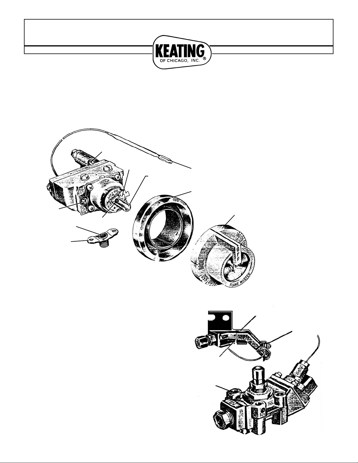
Model UA Flame Master® consists of a gas griddle control and automatic shut-off valve with No. 70
pilot burner, Temperature range–”BROIL” down to 140°F.
70
“LIGHT”
(STANDBY PILOT)
TEMPERATURE
RESPONSIVE
BULB
FIGURE 2
No. 70
PILOT BURNER
MSC SHUT-OFF
VALV E
TOP BURNER
PILOT ADJUSTOR
CALIBRATION
PLATE AND MARKS
“D”STEM
(SHOWN AT APPROX.
450 DIAL SETTING)
BEZEL
GRIDDLE TEMPERATURE
FIGURE 1
TEMPERATURE
DIAL
SELECT-A-GAS
PILOT ADJUSTOR
CALIBRATION
SCREW
GASKET
INLET FITTING
MOUNTING FLANGE
Lotempoc
4-96
ADJUSTMENTS:
SELECT-A-GAS PILOT ADJUSTOR
Under NORMAL GAS PRESSURES, the standby and heater pilot flames
do not require adjustment. Simply remove dial assembly and bezel, then
turn the SELECT-A-GAS ADJUSTOR to the proper gas position, making
sure standby pilot is ignited.
Note: Clockwise to full stop for natural gas and counterclockwise to full
stop for LP-gas. “OFF” is midway between NAT and LP positions.
Where ABNORMAL GAS PRESSURES exist, variable pilot adjustments
can be made for STANDBY PILOT on NATURAL gas and for HEATER
PILOT ON LP-gas. It is not necessary to reduce BOTH pilot flames on
either type of gas.
FOR NATURAL gas, turn adjustor approximately halfway between full open
(NAT) and “OFF”. This lowers STANDBY pilot flame which should
not extend higher than mounting holes of pilot bracket (See Figure 3).
FOR LP-gas, turn adjustor approximately halfway between full open (LP)
and “OFF”. This lowers HEATER pilot flame. The size of HEATER pilot
flame should be checked and adjusted, when griddle is “cold”. If
adjustment is necessary, adjust flame to that it surrounds “temperature
responsive bulb” (See Figure 2).
TOP BURNER PILOT ADJUSTMENT
(See Figure 1) Controls equipped with filtered top burner pilots are
adjusted by one adjustment screw as follows:
Turn adjustor clockwise to lower the top burner
pilot flame or counterclockwise to increase the flame.
TO RECALIBRATE GRIDDLE CONTROL
To check griddle temperatures when recalibrating, use a test instrument or
equivalent. Place the thermocouple of test instrument in the middle of the
griddle.
All AUTOMATIC FLAME MASTER griddle controls are carefully calibrated
at the factory (i.e.: The dial is properly set to control griddle
temperatures accurately). It is recommended that only a qualified service
man perform this adjustment because calibration should not be changed
until sufficient experience with cooking results has definitely proved that
the control is not maintaining proper griddle temperatures.
1. Light griddle burner and turn dial to 350 mark.
2. Allow griddle to heat about 15 to 20 minutes.
NOTE: The griddle burner will snap at full burner rate “ON” “OFF” at all dial
settings up to 575 mark. No by-pass flame or by-pass adjustment is
needed.
3. After griddle burner has been on approximately 15 to 20 minutes, wait
and watch for the griddle burner to snap “off” and “on” then check griddle
temperature.
The griddle control should be recalibrated if a temperature variation from
350 degrees (dial setting) is greater than 25 degrees. If recalibration is
required, make the following adjustment.
4. Carefully remove dial assembly and bezel, by pulling straight out,
making sure “D” stem does not rotate in either direction which would
change the dial setting.
5. Insert a screwdriver through center of the “D” stem and engage
calibration adjustment screw. Using the screwdriver bit as a reference
point, turn calibration screw clockwise to obtain a lower temperature or
counterclockwise for a higher temperature. Each calibration mark on front
of calibration plate, represents 25°F. Be careful that “D” stem does not
move during this adjustment.
The griddle temperature should now increase or decrease, as required, to
agree with the 350 degree dial setting.
Example:–Dial Setting 350
Test Instrument reading 300° Fah.
The griddle control is 50° too low. Turn calibration screw counterclockwise two marks.
6. Replace bezel and dial, turning dial clockwise to “OFF”.
7. Recheck calibration by repeating step 1 except set dial at 350
mark. Check griddle temperature again as instructed in steps 2 and 3.
If the griddle temperature is not within 25 degrees of the dial setting
(350 degrees), it means that the sensing element is defective and the
griddle control should be replaced.
8. Turn dial clockwise to OFF position.
ALTERNATE CALIBRATION:
To insure “D” stem not moving while making calibration adjustment,
turn dial to “OFF” before proceeding with step 4 and 5. Replace bezel
and dial to “OFF” position then recheck calibration beginning with
Step 1.
www.keatingofchicago.com 1-800-KEATING
SERVICE INSTRUCTIONS
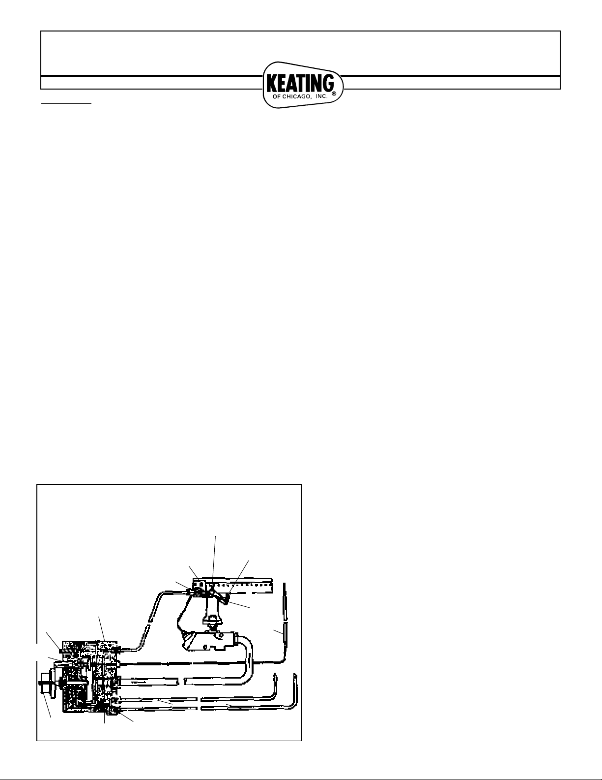
*NOTE:
STANDBY PILOT FLAME
SHOULD NOT EXTEND
HIGHER THAN MOUNTING
HOLE IN PILOT BRACKET.
PILOT BRACKET
NO. 70
SINGLE TUBE
PILOT BURNER
UA TYPE CONTROL
SELECT-A-GAS
PILOT ADJUSTOR
INTEGRAL
GAS COCK
TEMPERATURE
DIAL
FILTER
TOP BURNER
PILOT ADJUSTOR
FIGURE 3
TOP BURNER PILOTS
MISC SHUT-OFF VALVE
GRIDDLE
TEMPERATURE
SENSING
BULB
TEMPERATURE
RESPONSIVE
BULB
GRIDDLE BURN-
HEATER
PILOT FLAME
*STANDBY
PILOT FLAME
continued
Lotempoc
4-96
 Loading...