

Keating Of Chicago INSTANT RECOVERY ELECTRIC FRYER Service Manual
INSTANT
RECOVERY®
ELECTRIC
FRYER
SERVICE
MANUAL
KEEP THIS MANUAL FOR TRAINING NEW PERSONNEL
1-800-KEATING
www.keatingofchicago.com
elecFryPre2000_0310 03/13part#000784

i
TABLE OF CONTENTS
SECTION I INTRODUCTION
General . . . . . . . . . . . . . . . . . . . . . . . . . . . . . . . . . .1
Standard Features . . . . . . . . . . . . . . . . . . . . . . . . . .1
Model Variations . . . . . . . . . . . . . . . . . . . . . . . . . . .1
Safety Precautions . . . . . . . . . . . . . . . . . . . . . . . .1-2
SECTION II INSTALLATION
Damage During Shipment . . . . . . . . . . . . . . . . . . . .2
Installation . . . . . . . . . . . . . . . . . . . . . . . . . . . . . . . .2
Positioning . . . . . . . . . . . . . . . . . . . . . . . . . . . . . . . .2
Leveling . . . . . . . . . . . . . . . . . . . . . . . . . . . . . . . . . .2
Restraining Devices . . . . . . . . . . . . . . . . . . . . . . . . .3
Electrical Connection . . . . . . . . . . . . . . . . . . . . . . . .3
SECTION III OPERATING THE FRYER
Filling . . . . . . . . . . . . . . . . . . . . . . . . . . . . . . . . . .3-4
Melting . . . . . . . . . . . . . . . . . . . . . . . . . . . . . . . . . . .4
Cooking . . . . . . . . . . . . . . . . . . . . . . . . . . . . . . . .4-5
Shutdown . . . . . . . . . . . . . . . . . . . . . . . . . . . . . . . . .5
Draining . . . . . . . . . . . . . . . . . . . . . . . . . . . . . . . .5-6
Cleaning and Boil-Out . . . . . . . . . . . . . . . . . . . . .6-7
Electronic Timers . . . . . . . . . . . . . . . . . . . . . . . . .7-8
SECTION IV MAINTENANCE
Warranty Repairs . . . . . . . . . . . . . . . . . . . . . . . . . . .8
Preventive Maintenance . . . . . . . . . . . . . . . . . . . . .8
Oil Breakdown . . . . . . . . . . . . . . . . . . . . . . . . . . . . .9
Limited Calibration . . . . . . . . . . . . . . . . . . . . . . . . . .9
Thermostat Bulb Positioning . . . . . . . . . . . . . . . . . .9
Hi-Limit Check . . . . . . . . . . . . . . . . . . . . . . . . . . . . .9
SECTION V SERVICE DIAGNOSIS
General . . . . . . . . . . . . . . . . . . . . . . . . . . . . . . . . .10
Trouble Shooting Charts . . . . . . . . . . . . . . . . .10-12
SECTION VI PARTS LIST
Ordering Parts . . . . . . . . . . . . . . . . . . . . . . . . . . . .12
Warning and Operating Plates . . . . . . . . . . . . . . .12
Electric Fryer Parts List . . . . . . . . . . . . . . . . . . . . .13
Electric Fryer Assembly I . . . . . . . . . . . . . . . . . . . .14
Electric Fryer Assembly II . . . . . . . . . . . . . . . . . . .14
BB Control Panel Parts List . . . . . . . . . . . . . . . . . .15
TS Control Panel Parts List . . . . . . . . . . . . . . . . . .16
10x11”, 14” Basket-Lift Control Panel . . . . . . . . . .17
18” - 34”x24” Basket-Lift Control Panel . . . . . . . . .18
14” Basket-Lift Housing and
Roller Guide Parts List . . . . . . . . . . . . . . . . . . . . .19
18” - 34”x24” Basket-Lift Housing, Roller
Guide and Transformer Box Parts List . . . . . . . . .20
SECTION VII WIRING DIAGRAMS
BB Wiring Diagrams . . . . . . . . . . . . . . . . . . . . . . .21
TS Wiring Diagrams . . . . . . . . . . . . . . . . . . . . .22-23
Basket-Lift Wiring Diagrams . . . . . . . . . . . . . . .24-25
SECTION VIII FRYER SPECIFICATIONS
BB Models . . . . . . . . . . . . . . . . . . . . . . . . . . . . . . .26
TS Models . . . . . . . . . . . . . . . . . . . . . . . . . . . . . . .27
Warranty
Notice: This operating, installation, and service
manual should be given to the user. The operator of the
fryer should be familiar with the functions and
operation of the fryer. This manual must be kept in a
prominent, easily reachable location near the fryer.
Notice: Keating of Chicago, Inc. (manufacturer)
reserves the right to change specifications at any time.
FOR YOUR SAFETY: DO NOT STORE OR USE
GASOLINE OR OTHER FLAMMABLE VAPORS OR
LIQUIDS IN THE VICINITY OF THIS OR ANY
OTHER APPLIANCE.
WARNING: IMPROPER INSTALLATION,
ADJUSTMENT, ALTERATION, SERVICE OR
MAINTENANCE CAN CAUSE PROPERTY
DAMAGE, INJURY OR DEATH. READ THE
INSTALLATION, OPERATING AND MAINTENANCE
INSTRUCTIONS THOROUGHLY BEFORE
INSTALLING OR SERVICING THIS EQUIPMENT.
1
I INTRODUCTION
GENERAL
Keating Instant Recovery® Electric Fryers are
designed to give maximum production efficiency,
delivering high quality food products. The following
design features are incorporated in Keating Instant
Recovery® Electric Fryers.
STANDARD
FEATURES
Highly polished stainless steel fryer vessel
Highly polished stainless steel front
Highly polished stainless steel elements
Highly polished stainless steel thermostat bulb
Highly polished stainless steel Hi-Limit sensor
True Cold Zone for proper sedimentation
Grid screen over elements
Melt cycle
1” full port front drain valve on 10x11 and 14;
1-1/4” for 18 and larger
High temperature limit control with manual reset
Patented accurate temperature control system ±2°F
Ideal 35” working height
One pair of split baskets or one full-size basket
Circuit breaker protection for 208-240V 14 to 34x24
Models.
STANDARD
ACCESSORIES
Keating Klenzer Sample
Keating Sea Powder Sample
Drain clean out rod
STANDARD FRYERS
Sizes: 10x11 to 34x24
Oil capacity 30 to 210 pounds
NSF, UL and CUL listed.
MODEL VARIATIONS
BB Model: BB Model Fryers feature Power On and
Element On indicating lights, a melt cycle and an
electric stainless steel thermostat. The 14BB model
can cook up to 72 lbs. of frozen fries or 75 lbs. of
chicken per hour.
TS Model: TS Model Fryers have the highest input of
all Keating fryers. The TS Model features a melt cycle,
and electric stainless steel thermostat, two electronic
timers and four indicating lights which display the
status of the fryer’s operation. The 14TS Model can
cook up to 90 lbs. of frozen fries or 75 lbs. of chicken
per hour.
TS Basket-Lift Model: TS Basket-Lift Model Fryers
come with all the same features as the TS Model. The
Basket-Lift mechanism lowers the baskets of food into
the oil when the timer button is pressed and raises the
baskets when the cooking cycle is complete. Split
baskets are used for all models. (Triple baskets
available with some models.)
CM Model: BB and TS Counter Model Fryers are
equipped with all of the same features as the BB and
TS Models respectively, but take up less than three
square feet of counter space. The 10x11CM Model can
cook up to 36 lbs. of frozen fries per hour and the
14CM Model can cook up to 72 lbs. per hour.
CPU Model: CPU Model Fryers have the same input
as the TS Models. The panel of switches and indicating
lights are also the same. A programmable computer
replaces the two timers and thermostat. A secondary
thermostat, located in the fryer’s cabinet, permits frying
without the computer.
SAFETY
PRECAUTIONS
WARNING
THIS SYMBOL WARNS YOU THAT SERIOUS BURNS
OR OTHER INJURIES MAY RESULT IF SAFETY
INSTRUCTIONS ARE NOT FOLLOWED.
This service manual should be retained in a safe place
for future reference. The installation of your new fryer
must conform to current codes, with the current National
Electrical Code ANSI/NFPA 70 or Canadian Electrical
Code CAN 22.2 as applicable.
Your ventilation hood, when installed, must conform to
the current ANSI/NFPA 96 standard.
You must maintain this appliance free and clear from
combustibles.
Adequate clearance for servicing and proper operation
must be maintained. Your fryer is designed to be
serviced from the front.
Keating commercial fryers are intended for other than
household use.
ALWAYS instruct new employees on proper fryer operation.
A fryer should be operated ONLY by properly trained
personnel.
ALWAYS turn fryer off each night.
ALWAYS turn fryer off at customer power panel before
servicing.
NEVER leave a fryer unattended during operation.

2
NEVER move a fryer when full of hot oil.
NEVER introduce objects or liquids into fryer, while
operational, which are not designed or made for
cooking.
THIS FRYER MAY NOT BE ALTERED, MODIFIED OR
CHANGED IN ANY WAY.
WARNING
IMPROPER INSTALLATION, SERVICE OR
MAINTENANCE CAN CAUSE PROPERTY
DAMAGE, INJURY OR DEATH. READ THESE
INSTALLATION, OPERATING AND MAINTENANCE
INSTRUCTIONS THOROUGHLY BEFORE
INSTALLING OR SERVICING THIS EQUIPMENT.
II INSTALLATION
This fryer MUST be installed, inspected, calibrated and
serviced by qualified and/or certified and/or licensed
service personnel - you may void your Keating
warranty if installation is not completed per local,
national and Keating specifications. Contact your
dealer for assistance.
DAMAGE DURING
SHIPMENT
The fryer has been assembled, tested and inspected at
the factory. Upon arrival, the complete fryer should be
checked for any damage that may have occurred
during shipment.
The carrier is responsible for all damage in transit
whether visible or concealed. Do not pay for the freight
bill until the fryer has been thoroughly checked for
damage. If concealed damage is found later, contact
the carrier immediately to file a claim.
What to do if equipment arrives damaged:
VISIBLE LOSS OR DAMAGE – Be certain to note
this on the freight or express receipt and have it
signed by the delivery person.
FILE CLAIM FOR DAMAGES IMMEDIATELY –
Regardless of extent of damage.
CONCEALED LOSS OR DAMAGE – If damage is
noticed when equipment is unpacked, notify the
freight company immediately, and file a “concealed
damage claim”. This MUST be done immediately. Be
sure to retain the shipping container for inspection.
Keating does not assume responsibility for Loss OR
Damage incurred in transit.
INSTALLATION
Installation must conform with local codes or, in
absence of local codes, with the current National
Electrical Code ANSI/NFPA 70 or Canadian Electrical
Code CAN 22.2 as applicable.
NOTE: For safety purposes, all Hi-Limit controls are
manually reset. Always check the Hi-Limit reset button
before attempting to use the fryer. It is possible that the
Hi-Limit button may have been accidentally activated
on a new fryer while in transit.
POSITIONING
The fryer must be placed under an exhaust hood with
a fire retardant system. Your ventilation hood, when
installed, must conform to the current ANSI/NFPA 96
standard. ALL connections and placement must
comply with current local and national codes. It is the
responsibility of the owner and local installer to comply
with these regulations when installing the fryer.
Counter model and floor model fryers must be
restrained to prevent tipping when installed in order
to avoid splashing, spilling, etc. of hot liquid. The
restraining method may be a manner of installation or
by separate means.
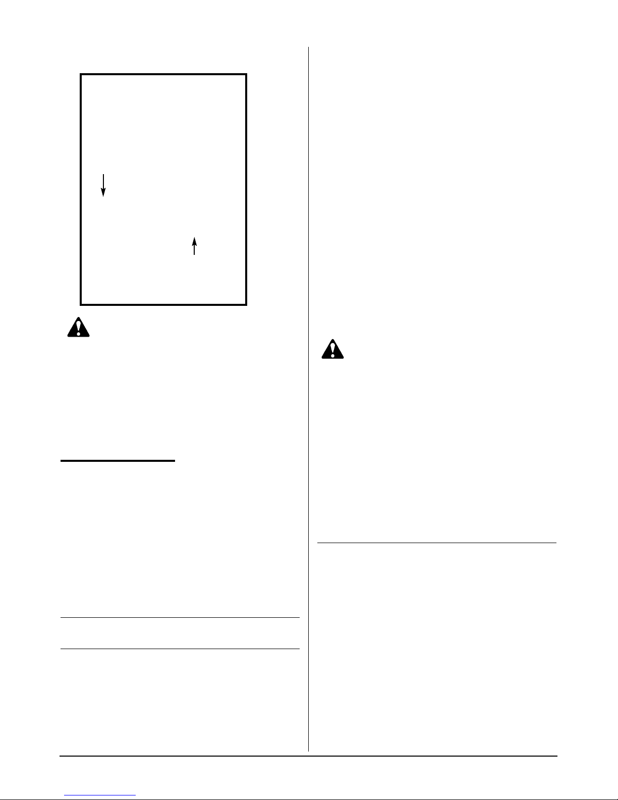
LEVELING
The fryer will operate at its highest efficiency when
properly leveled. Place a level on fryer vessel from side
to side. For fryers on legs, the bottom foot of the leg is
adjustable. Looking from the bottom of the foot, turn
counter clockwise to decrease height or clockwise to
increase height until level. For fryers on casters, the
casters are adjustable by loosening the jam nut and
turning the caster in or out. When the desired level is
reached, tighten the jam nut. Adjustments of more than
19mm are not recommended on any caster. The same
procedure should be followed to level the fryer from
front to back.
Figure 2-1 Figure 2-2
3
RESTRAINING
DEVICES
On fryer installations with casters, casters and jam nuts
must be completely tightened. Adequate means must
also be provided to limit the movement of the
appliance.
ELECTRICAL
CONNECTION
The Keating Instant Recovery® Electric fryer is
equipped with a three wire terminal block for customer
connections. The terminal block is located behind the
fryer door on the right side behind a panel (held in
place by two screws). Compare the fryer terminal
connections to the appropriate wiring diagram for the
fryer (see pages 31 thru 36) to see if the fryer is
connected three phase or single phase. All wires/cords,
plugs, receptacles and circuit breakers must be sized
adequately for the full load rating of the fryer as
specified by local codes, or in the absence of local
codes, by the current National Electrical Code
ANSI/NFPA 70 or Canadian Electrical Code CAN 22.2
as applicable.
The Keating Electric Fryer is also equipped with a
grounding lug next to the terminal block. For proper
grounding procedures, see local codes or, in the
absence of local codes, by the current National
Electrical Code ANSI/NFPA 70 or Canadian Electrical
Code CAN 22.2 as applicable.
NOTE: The connections to the fryer can be changed in
the field from three phase to single phase or from
single phase to three phase. This can be done by
simply changing the wiring at the terminal block. To
change the connections for your fryer, see the
appropriate wiring diagram for your fryer on pages 31
thru 36.
NOTE: For fryers rated at 208-240 volts, the amperage
ratings marked on the nameplates of the fryers are
listed at 240 volts as required by UL. If your fryer is to
be fed by a 208 or 220 volt system, consult the Keating
Fryer Specifications on pages 37 and 38 to determine
the full load rating of the fryer.
NOTE: Some fryers with Basket-Lifts, Zero-Space™
Filters (model BB ZS or TS ZS) or Central Filters may
have separate 120 volt control circuit connections.
Fryers with Basket-Lifts or Zero-Space™ filters will
need the connections made to a separate smaller
terminal block located near the larger terminal block for
the 208-240 volt connections or inside a separate
wiring box. This terminal block will have one black and
one white wire connected to it. Fryers with Central
Filters will need the connections made inside the
Central Filter junction box. For proper connections,
refer to the appropriate wiring diagram on pages 31
thru 36.
NOTE: A copy of the wiring diagram is included with
this manual.
NOTE: A hole has been punched in the rear of the fryer
cabinet for a cord or conduit exit. If a cord is used, the
National Electrical Code, UL standards and most local
codes require a bushing or strain relief (not provided by
Keating) to protect the cord.
CALIBRATION
For Calibration refer to page 9 - Calibration.
III OPERATING
FILLING
NOTE: Before filling the fryer make certain the fryer
vessel is sanitized, dry and the drain valve is
completely closed. Refer to figures 3-4, 3-5 on pages 6
and 7 for location of drain valve.
WARNING
BE SURE THE HEATING ELEMENTS ARE
COMPLETELY COVERED WITH OIL BEFORE
SWITCHING THE FRYER ON. IF OIL LEVEL DROPS
BELOW TOP OF HEATING ELEMENTS, SEVERE
DAMAGE TO FRYER AND INJURY TO OPERATOR
MAY RESULT.
WARNING
WATER IN ANY FORM AND HOT OIL DON’T MIX!!!
CAUTION: Oil expands when heated. The “Fill Level”
line has been provided to ensure optimum cooking
while ensuring the safety of the operator. Do not overfill
the fryer vessel.
Figure 3-1
Fill Level Line

4
BB & TS, CPU and Basket-Lift Models
1. Fill the fryer vessel with oil up to the “Fill Level” line.
(Refer to pages 37 and 38 for the oil capacity of
your particular model).
2. If using solid shortening is used, remove screen
and firmly pack solid shortening between the
heating elements. Proceed to - Melting section
below, for instructions on use of the melt cycle.
MELTING
The Keating Melt Cycle safely melts solid shortening in
the fryer vessel without scorching.
WARNING
BEFORE ATTEMPTING TO LIGHT THE FRYER,
MAKE SURE THE ELECTRIC CONNECTIONS ARE
SECURE AND HAVE BEEN LEAK TESTED AND
THE FRYER HAS BEEN PROPERLY FILLED WITH
OIL.
A. BB, TS and Basket-Lift Models
1. Set the thermostat to the desired temperature.
2. If using solid shortening, set On/Off/Melt switch to
the “MELT” position. Stay in the “MELT” cycle until
the shortening has melted completely and is at the
“Fill Level” line before switching to the “ON”
position for cooking.
B. CPU Models
*See separate computer instructions or call
1-800-KEATING.
NOTE: During the “MELT” cycle, the elements are on
for approximately 5-7 seconds and off for
approximately 35 seconds.
Figure 3-2
BB, TS and TS Basket-Lift Control Panels
COOKING
Keating Instant Recovery® Electric Fryers are
designed to provide maximum production efficiency
and deliver high quality food products.
Low-temperature cooking, highly polished stainless
steel and a true COLD ZONE mean extended oil life.
Follow cooking procedures below for your model.
WARNING
OPERATION OF THIS FRYER SHOULD BE
LIMITED TO PERSONNEL WHO HAVE BEEN
THOROUGHLY TRAINED IN OPERATING
PROCEDURES.
USE ONLY KEATING APPROVED BASKETS IN
YOUR FRYER. NEVER OVERFILL FRY BASKETS.
DO NOT BANG BASKETS ON BASKET HANGERS
OR FRYER VESSEL.
CARE SHOULD BE TAKEN WHEN LOWERING
BASKETS INTO FRYER TO PREVENT SPLASHING
HOT OIL FROM FRYER VESSEL.
NEVER LIFT BASKETS DIRECTLY OUT OF THE
FRYER VESSEL WITHOUT DRAINING AS SEVERE
INJURY MAY RESULT.
NOTE: For safety purposes, all Hi-Limit controls are
manually reset. Always check the Hi-Limit reset button
before attempting to use the fryer. If the Hi-Limit has
tripped, the fryer will not operate.
NOTE: For a fryer with a Central or Zero-Space™
Filter, always check the rear drain operating handle
before attempting to use the fryer. A safety switch
prevents the fryer from operating if the handle is not
pushed in completely.
A. BB Models
1. Fill fryer as described on page 3 and 4 - Filling.
2. Set On/Off switch to the “ON” position. “ELEMENT
ON” light will be illuminated.
3. Set thermostat to the desired frying temperature
(between 325°C and 335°C).
4. When the oil reaches the desired frying
temperature and the “ELEMENT ON” light goes
off, lower filled basket(s) slowly into the hot oil.
5. When cooking cycle is complete, carefully lift
basket(s) out of oil. Place them on basket hanger
rods (on splashback of fryer) to allow draining of
excess oil.
BB MODEL
10x11, 14 TS BASKET LIFT MODEL
18 & above TS BASKET-LIFT MODEL
TS MODEL

5
B. TS Model
1. Fill fryer as described on page 3 and 4 - Filling.
2. Set On/Off switch to the “ON” position. “HEAT” light
will be illuminated.
3. Set thermostat to the desired frying temperature
(between 325°C and 335°C).
4. When the oil reaches the desired frying
temperature, the “HEAT” light will go off, and the
“COOK” light will illuminate.
5. Lower filled basket(s) slowly into the hot oil.
6. Set timer for left or right side basket, whichever is
being lowered into oil.
7. When timer sounds, lift basket out of oil. Place on
basket hanger rods (on splashback of fryer) to
allow draining of excess oil.
C. Basket-Lift Models
1. Fill fryer as described on pages 3 and 4 - Filling.
2. Set On/Off switch to the “ON” position. “HEAT” light
will be illuminated.
3. Set thermostat to the desired frying temperature
(between 325°C and 335°C).
4. When the oil reaches the desired frying
temperature, the “HEAT” light will go off, and the
“COOK” light will illuminate.
5. Fill basket(s) to proper level and place on upper bar
of lift rod(s).
6. Set timer(s) to desired cooking time. For
programming timers see page 7
7. Push “START-STOP” button on timer(s). Basket(s)
will automatically lower into fryer vessel.
8. When cooking cycle is complete, an audible alarm
will sound and the basket(s) will raise
automatically. Allow oil to drain before removing
baskets.
D. CPU Model
*See separate computer instructions or call
1-800-KEATING
SHUTDOWN
A. BB, TS and Basket-Lift Models
1. Turn fryer On/Off/Melt switch to “OFF” position.
B. CPU Model
1. Set Main Power On/Off switch to the “OFF”
position.
DRAINING
WARNING
ALWAYS SHUT THE FRYER OFF COMPLETELY
BEFORE DRAINING. THE FRYER SHOULD BE
DRAINED ONLY UNDER THE SUPERVISION OF
PROPERLY TRAINED PERSONNEL. A DRAIN PIPE
AND COVERED CONTAINER SUITABLE FOR USE
WITH HOT OIL SHOULD BE USED TO ENSURE THE
SAFETY OF THE OPERATOR.
1. Operator should be outfitted with proper attire
including:
– Oil and heat resistant gloves
– Oil and heat resistant apron
– Safety goggles
– Oil and heat resistant footwear
Figure 3-3
Operator in safety gear
2. Turn off the fryer and open the door.
3. For front drain fryers, put approved container under
drain valve. For fryers with a central filter, slide filter
drawer in completely.
4. For front drain fryers, slowly turn handle forward to
avoid splashing. The drain valve will be completely
open after 1/4 turn.
5. For units with rear drain valves, slowly pull drain
valve operating handle straight out (unhook from
metal latch first).
Figure 3-4
Front drain valve
6
Figure 3-5
Rear drain valve
WARNING
UNDER NO CIRCUMSTANCES SHOULD YOU
PERMIT HOT OIL TO COME IN CONTACT WITH
WATER OR ICE. ALL DRAINING SHOULD BE DONE
UNDER THE SUPERVISION OF PROPERLY
TRAINED PERSONNEL. A DRAIN PIPE AND
COVERED CONTAINER SUITABLE FOR USE WITH
HOT OIL SHOULD BE USED WHENEVER A FRYER
IS DRAINED. ALWAYS DRAIN OIL INTO A
COVERED RECEPTACLE.
CLEANING AND
BOIL-OUT
When cleaning and boiling out your fryer use Keating
Sea Powder and Keating Klenzer to keep your fryer in
top condition. Keating Sea Powder dissolves any
grease build up—even carbonized grease in fryer
vessels—one of the leading causes of premature oil
breakdown. And once your fryer vessel is clean, use
Keating Klenzer, the finest dry stainless steel polish
available, to restore your Keating Instant Recovery®
Electric fryers’ exterior to its original luster. Both
Keating Klenzer and Sea Powder are USDA approved.
CAUTION: Disconnect electric power source before
doing any cleaning.
CAUTION: To avoid damaging the fryer, do not power
wash, spray or hose it down while cleaning.
Figure 3-6
Keating Klenzer and Sea Powder
1. Put on safety attire. See page 5 - Draining.
2. Turn the fryer off.
3. Drain oil from fryer, see page 5. Filtering may be
done at this step.
4. Remove oil container to a secure area to prevent
accidental spillage.
5. Fill fryer vessel to “Fill Level” line with water.
WARNING
UNDER NO CIRCUMSTANCES SHOULD THE
FRYER BE LEFT UNATTENDED DURING BOIL-OUT.
TRAINED PERSONNEL MUST BE PRESENT
DURING THE PROCEDURE TO PREVENT BOIL
OVER OR TO TURN OFF THE POWER IF WATER
DROPS BELOW HEAT TRANSFER TUBES.
6. Set thermostat and turn fryer on to bring water to a
gentle boil.
7. Once boil has been reached, turn fryer off.
8. Dissolve 2/3 cup of Keating Sea Powder for every
five gallons of water and let soak for 1/2 hour. If
there is a large build-up of carbonized grease,
allow fryer to soak overnight.
CAUTION: Do not damage or remove thermostat bulb
as this may affect the accuracy of the fryer.
9. While soaking, a natural fiber brush may be used
to scrub the tubes and inside walls of fryer.
10. Drain the water and Sea Powder into a dry suitable
receptacle and remove from cooking area.
11. Spread Keating Klenzer liberally on sides of fryer
vessel.
12. At this point, a non-abrasive scouring pad may be
used to remove the now softened carbonized
grease.
13. Thoroughly rinse fryer vessel with potable water to
remove all Klenzer.
DRAIN
VALV E
HANDLE
RETURN
VALVE HANDLE
(Closed Position)
7
14. Prior to refilling with oil, wipe the inside of the fryer
vessel making sure all water and Klenzer has been
removed.
WARNING
WATER IN ANY FORM AND HOT OIL DON’T MIX!!!
15. Close drain valve.
WARNING
FAILURE TO CLOSE DRAIN VALVE BEFORE
REFILLING THE FRYER MAY RESULT IN SERIOUS
INJURY.
WARNING
WHEN YOUR FRYER IS BEING USED IN
CONJUNCTION WITH A CENTRAL FILTER,
DISCONNECT POWER SUPPLY BEFORE
RESETTING MOTOR TO PREVENT SERIOUS
INJURY WHEN RESET SWITCH IS ENGAGED (SEE
FILTER MANUAL).
16. Check thermostat bulb positioning - see page 9.
17. Refill the fryer with new or filtered oil.
ELECTRONIC
CONTROL
TIMERS
The electronic timers provide a clearly visible and
accurate display and are very easy to use.
"10X11" & 14" TS
MODELS
A. “Keating” Electronic Timer
B. How to program the “Keating” Electronic
Timer
The Keating Electronic Timer is programmable to
four different timer ranges with two different alarm
modes for each time range.
The timers are shipped from the factory preset to
program 5: Minutes : seconds (00:01 to 59:59) with
continuous alarm
To program another time range or alarm mode
perform the following steps:
1. Turn off the power
2. Press the “down arrow “ button while turning the
power on.
3. Release the button after the display turns on.
4. A number from 0 to 7 will appear.
This number corresponds to:

8
0 = Seconds (000.1 to 999.9) 5 second alarm
1 = Minutes : Seconds (00:01 to 59:59) 5 second
alarm
2 = Seconds (0001 to 9999) 5 second alarm
3 = Hours : Minutes (00:01 to 23:59) 5 second
alarm
4 = Seconds (000.1 to 999.9) continuous alarm
5 = Minutes : Seconds (00:01 to 59:59)
continuous alarm
6 = Seconds (0001 to 9999) continuous alarm
7 = Hours : Minutes (00:01 to 23:59) continuous
alarm
5. Use the “down arrow “ button to select the
desired time range.
6. Turn off the power.
7. Wait 2 seconds.
8. Turn on the power. (the timer will remain in the
new time range until programmed).
The electronic timers, used on 18” and above
Basket-Lift models, provide a clearly visible and
accurate display and are very easy to use. One
knob sets the time and one button controls all
operations. The display can show cooking or
clock time.
18"-34"X24" TS
MODELS
A. Timer Mode
1. Turn round knob clockwise (toward “+”) to increase
time or counterclockwise (toward “-”) to decrease
time.
NOTE: When programming the timer up to one minute,
the display goes up or down in seconds only. After one
minute, the display goes up or down in ten minute
increments.
2. Push start/stop button to start timer.
3. When buzzer sounds, push start/stop button to shut
off buzzer. Display will go blank.
4. Push start/stop button again to restore cycle time to
display.
5. To clear display, turn round knob fully
counterclockwise (toward “-”).
B. Clock Mode
1. To set time, hold clock (“”) button in and turn knob
clockwise (toward “+”) to increase time or
counterclockwise (toward “-”) to decrease time.
2. To display timer cycle time, push start/stop button.
3. If display is blank, pushing the clock button will
restore clock time to display.
C. To determine whether timer is in timer mode or
clock mode
1. Timer mode - display will show decimal point in
upper position (“10
.
08”).
2. Clock mode - display will show a decimal point in
lower position (“10.08”).
OPTIONAL TIMER
OPERATING INSTRUCTIONS
PART # 056921
DIGITAL TIMERS
The electronic timers, standard on TS
models, provide a clearly visible and
accurate display and are very easy to
use.
PROGRAMMING
To program the timers, the unit must be in the idle mode.
Press and hold the set button for approximately two
seconds. The display will show “SEt”. Press the button for
the channel to be programmed. The display will show the
current setting for that channel. Use the up or down button
to increment or decrement the setting. When the setting is
correct, press and hold the set button again for
approximately two seconds. The display will show "StO"
for approximately two seconds and the timer will return to
normal operation. Repeat the process as necessary for
the other timers.
OPERATING LOGIC
When the timer is powered up, the display will show the
time setting for the channel that was operated last and the
relay output contacts will be open. To start a cycle, press
the desired channel button (1-3). The display will begin to
countdown from the preset time setting and the relay
output contacts will close. During the countdown the colon
will flash at a one-second rate. When the countdown has
reached "00:00" the relay output contacts will open, the
display will flash, and the audible alarm will sound. To
cancel the audible alarm, press any button.
PAUSE FEATURE
To pause a cycle in progress, press any button. The relay
output contacts will open, the display will flash, and the
countdown will pause. To resume the countdown, press
any button. The display will resume the normal countdown
and the relay output contacts will close.
CANCELING A CYCLE
To cancel a cycle in progress press and hold any button
for approximately two seconds. The relay output contacts
will open and the display will show the time setting for the
channel last used.
 Loading...