

KEEP THIS MANUAL FOR TRAINING NEW PERSONNEL
Keating Of Chicago, Inc.
1-800-KEATING
www.keatingofchicago.com
SERVICE MANUAL
TOP-SIDE
TM
COOKER
manufactured years
1998 - 2004

i
TABLE OF CONTENTS
SECTION I INTRODUCTION
General . . . . . . . . . . . . . . . . . . . . . . . . . . . . . . . . . .1
Standard Features . . . . . . . . . . . . . . . . . . . . . . . . . .1
Standard Accessories . . . . . . . . . . . . . . . . . . . . . . .1
Cooking Head Specifications . . . . . . . . . . . . . . . . . .1
Safety Precautions . . . . . . . . . . . . . . . . . . . . . . . . .1
SECTION II INSTALLATION
Damage During Shipment . . . . . . . . . . . . . . . . . . . .1
Installation . . . . . . . . . . . . . . . . . . . . . . . . . . . . . . . .1
Conditioning the Cooking Head . . . . . . . . . . . . . . . .2
Electrical Connection . . . . . . . . . . . . . . . . . . . . . . . .2
SECTION III OPERATING
Cooking . . . . . . . . . . . . . . . . . . . . . . . . . . . . . . . . . .2
Cooking Height Adjustment . . . . . . . . . . . . . . . . . . .2
Shutdown . . . . . . . . . . . . . . . . . . . . . . . . . . . . . . . . .2
Cleaning Procedures . . . . . . . . . . . . . . . . . . . . . .2-3
Cleaning the Cooking Head . . . . . . . . . . . . . . . . . .3
SECTION IV MAINTENANCE
Warranty Repairs . . . . . . . . . . . . . . . . . . . . . . . . . . .3
Preventive Maintenance . . . . . . . . . . . . . . . . . . . .3-4
Installing a Cooking Sheet . . . . . . . . . . . . . . . . . . . .4
Handling Cooking Sheets . . . . . . . . . . . . . . . . . . . .4
Leveling of Cooking Head . . . . . . . . . . . . . . . . . .4-5
SECTION V SERVICE DIAGNOSIS
Trouble-Shooting Chart . . . . . . . . . . . . . . . . . . . . . .5
Thermostat Replacement Instructions . . . . . . . . .6-7
SECTION VI PARTS LIST
Ordering Parts . . . . . . . . . . . . . . . . . . . . . . . . . . . . .8
Warning and Operating Plates . . . . . . . . . . . . . . . .8
Top-SideTMCooking Head (Exploded View) . . . . . . .8
Top-Side
TM
Cooking Head Parts List . . . . . . . . . . . .9
Control Panel Assembly . . . . . . . . . . . . . . . . . . . .10
SECTION VII WIRING DIAGRAMS
Wiring Diagrams . . . . . . . . . . . . . . . . . . . . . . . . . .11
3/09 TopSide
NOTICE: This operating, installation, and service manual should be given to the user. The operator of the griddle
should be familiar with the functions and operation of the griddle. This manual must be kept in a prominent, easily
reachable location near the griddle.
Notice: Keating of Chicago, Inc. (manufacturer) reserves the right to change specifications at any time.
ii
FOR YOUR SAFETY
DO NOT STORE OR
USE GASOLINE OR
OTHER FLAMMABLE
VAPORS OR LIQUIDS
IN THE VICINITY OF
THIS OR ANY OTHER
APPLIANCE.
WARNING
IMPROPER INSTALLATION, ADJUSTMENT,
ALTERATION, SERVICE OR MAINTENANCE
CAN CAUSE PROPERTY DAMAGE, INJURY
OR DEATH. READ THESE INSTALLATION,
OPERATING AND MAINTENANCE
INSTRUCTIONS THOROUGHLY BEFORE
INSTALLING OR SERVICING THIS
EQUIPMENT.
WARNING
Before obtaining access to terminals,
all supply circuits must be disconnected.
1
I INTRODUCTION
GENERAL
Keating Top-SideTMCookers are designed to give
maximum production efficiency, delivering high quality
food products. The following design features are
incorporated into Keating Top-Side
TM
Cookers.
STANDARD
FEATURES
Stainless steel control panel
Stainless steel head cover
MIRACLEAN® cooking surface
Proprietary USDA and UL listed polymer cooking
sheets
Electronic thermostat
Infinitely adjustable cooking height, from 1/8'' to 1
1
/2''
(3mm to 38mm)
STANDARD
ACCESSORIES
Proprietary USDA and UL listed polymer cooking
sheets (1)
NOTE: Keating of Chicago, Inc. (manufacturer)
reserves the right to change specifications at any time.
COOKING HEAD
SPECIFICATIONS
Each Top-SideTMcooking head is designed to be
connected to a 208, 220 or 240 volt single phase line.
HEIGHT WIDTH DEPTH WATTS AMPS
3-5/8'' 10-1/2'' 20'' 4,000 18
(92mm) (267mm) (508mm) @220V @220V
STANDARD
TOP-SIDE™
COOKERS
Sizes: 1 to 6 heads.
Mounting: Can be mounted to any standard
MIRACLEAN® gas or electric 30'' (762mm) deep
griddle (24'' deep plate / 610mm) up to 72" wide (up
to 6 heads maximum).
Cooking Surface: 10
1
/2'' (267mm) wide x 20''
(508mm) deep (per cooking head).
Number of heads: One head can be used for every
12'' (305mm) of plate width. Each Top-Side
TM
cooking head will be positioned over a griddle
thermostat to ensure peak efficiency.
ETL and ETL Sanitation listed.
SAFETY
PRECAUTIONS
WARNING
THIS SYMBOL WARNS YOU THAT SERIOUS
BURNS OR OTHER INJURIES MAY RESULT IF
SAFETY INSTRUCTIONS ARE NOT FOLLOWED.
DO NOT SUBMERGE THE TOP-SIDE
TM
COOKING
HEAD IN WATER.
CLEANING CHEMICALS OR UTENSILS USED
FOR CLEANING GRIDDLES WILL DAMAGE OR
DESTROY THE POLYMER COOKING SHEET.
NEVER USE A WATER JET TO CLEAN.
II INSTALLATION
This Top-SideTMCooker MUST be installed on a
Keating griddle only. Failure to do so voids the
warranty.
The Top-Side™ Cooker must be installed, inspected,
calibrated and serviced by qualified, certified and/or
licensed service personnel. Contact your dealer for
assistance.
DAMAGE DURING
SHIPMENT
The Top-SideTMCooker has been assembled, tested
and inspected at the factory. Upon arrival, the complete
Top-SideTMCooker should be thoroughly checked for
any damage that may have occurred during shipment.
What to do if equipment arrives damaged:
VISIBLE LOSS OR DAMAGE- Be certain to note this
on the freight or express receipt and have it signed by
the delivery person.
FILE CLAIM FOR DAMAGES IMMEDIATELYRegardless of extent of damage.
CONCEALED LOSS OR DAMAGE- If the damage is
noticed when the equipment is unpacked, notify the
freight company immediately, and file a “concealed
damage claim”. This MUST be done immediately. Be
sure to retain the shipping container for inspection.
Keating does not assume responsibility for loss OR
damage incurred in transit.
INSTALLATION
On new installations, your Top-Side™ Cooker has
already been factory installed, tested leveled and
inspected. When installing onto an existing
MIRACLEAN® griddle, use the specific instructions
included with the Top-Side™ Cooker.
2
ELECTRICAL
CONNECTION
Each Keating Top-SideTMCooking head is equipped
with a 9' (2.74m) neoprene covered, 12 gauge 4mm(2),
three wire with ground electrical cord. No plug is
provided. Each cooking head is rated 4000W, 18 amps,
single phase at 220 Volts (4.37kW, 19 amps, single
phase at 230 Volts) and is designed to be connected to
its own 208-240V single phase electrical supply. For
proper connecting and grounding procedure see local
codes, the National Electrical Code ANSI/NFPA 70
(latest edition) or Canadian Electrical Code CAN C22.1
(latest edition) as applicable.
WARNING
THIS APPLIANCE MUST BE EARTHED.
III OPERATING
CAUTION
Food will cook much faster with a Top-SideTMCooker
than with a griddle alone. Watch food while cooking or
use timers to ensure food will not be overcooked.
WARNING
OPERATION OF THE TOP-SIDETMCOOKER
SHOULD BE LIMITED TO PERSONNEL
THOROUGHLY TRAINED IN OPERATING
PROCEDURES.
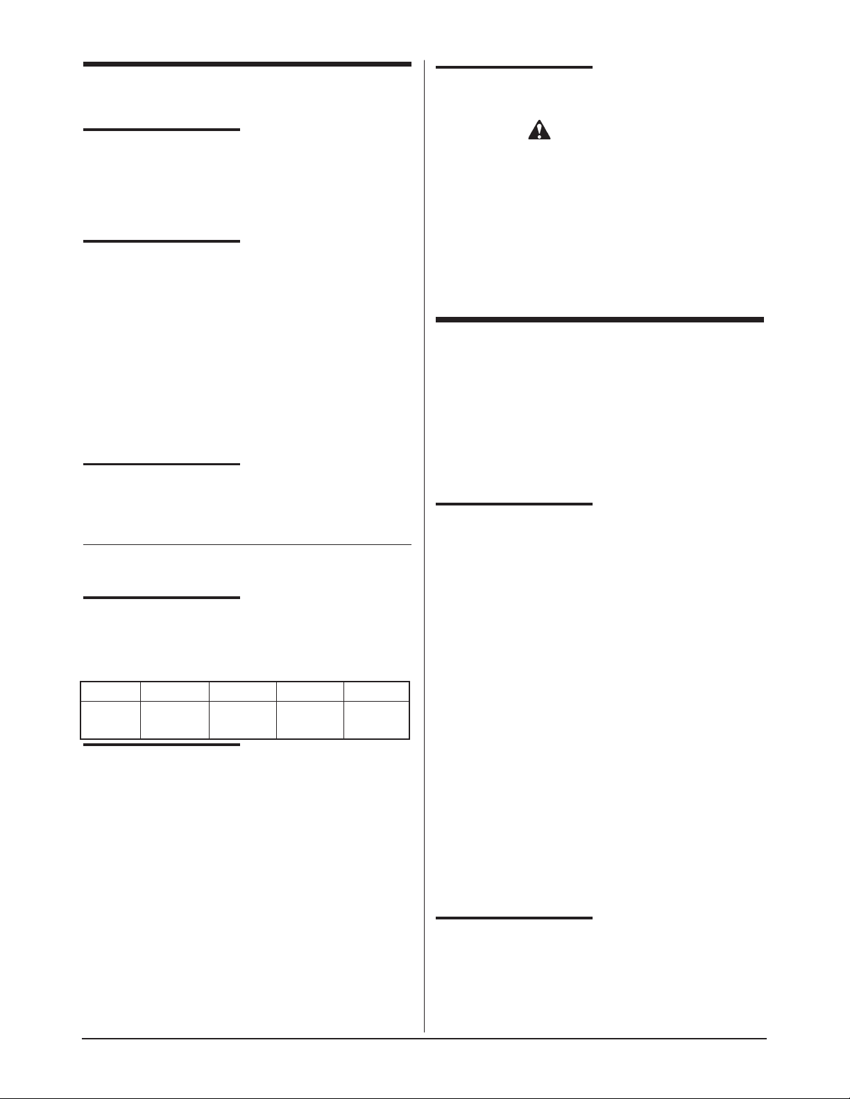
COOKING
1. Turn ON/OFF switch to “ON” position.
2. Set thermostat to desired temperature. Red
“ELEMENT ON” light will illuminate when the
element is on.
Figure 3-1
Top-Side
TM
Cooker Control Panel
pre-2005 model
Maximum thermostat setting 554°F (290°C)
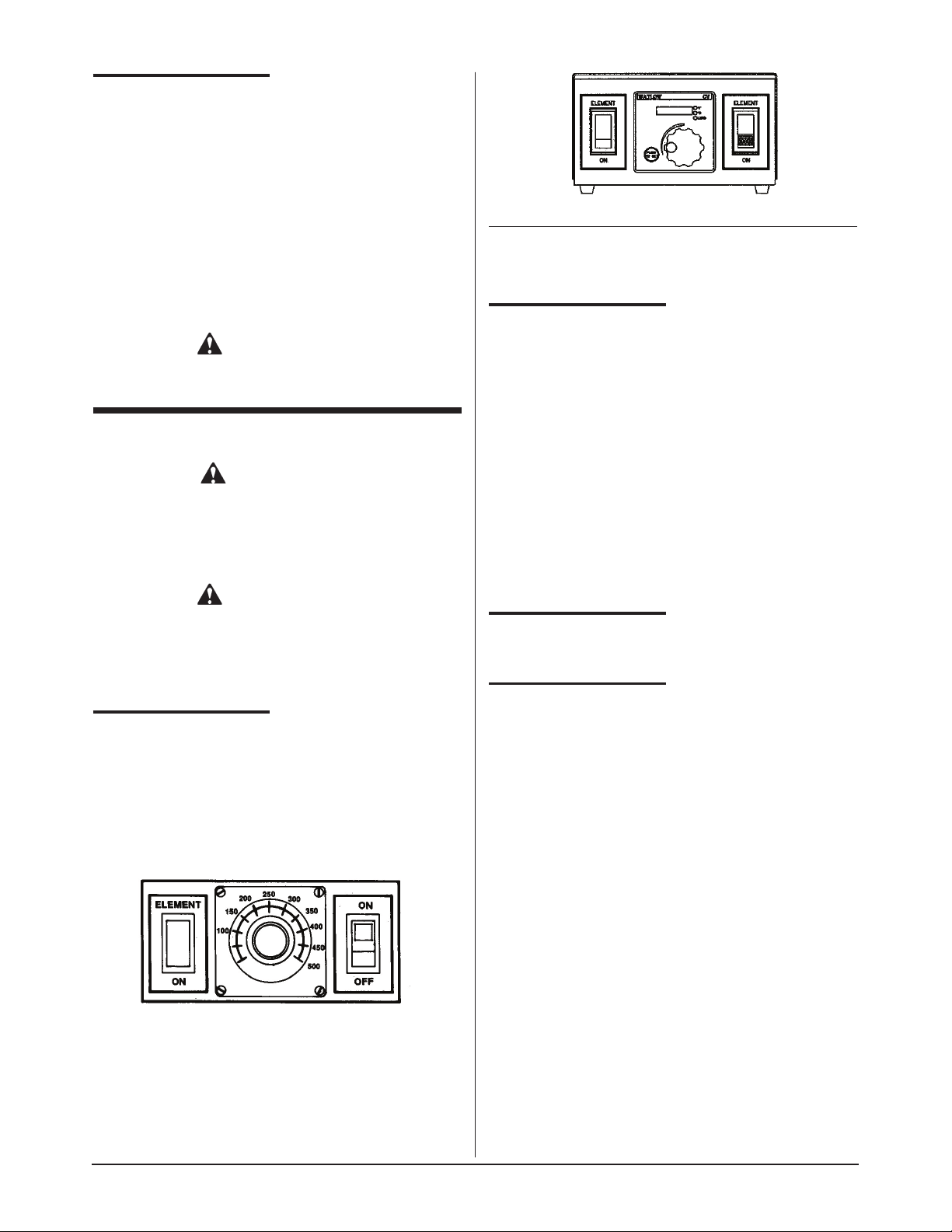
2005-current model
NOTE: The green “Power On” light will be illuminated
as long as there is power to the Top-Side
TM
Cooker.
COOKING HEIGHT
ADJUSTMENT
Keating’s Top-SideTMCooker has been designed to
allow you infinite height adjustments from 1/8'' to 11/2 ''
(approximately 3mm to 38mm). An adjusting knob
allows fast and precise height adjustment.
Clockwise movement of the knob will increase the
spacing; counter clockwise movement will decrease
the spacing. Each turn of the adjusting knob represents
1/8'' (approximately 3mm) movement.
Experimentation will give you the best cooking height
for each type of food product. The cooking head should
contact the product firmly to ensure optimum heat
distribution without flattening the product.
SHUTDOWN
Turn ON/OFF switch to “OFF” position.
CLEANING
PROCEDURES
A. Keating Cooking Sheets
Clean cooking sheets with a damp soft cloth after
each run of product (a Turkish towel works best).

3
WARNING
THE COOKING HEAD WILL BE HOT. USE PROPER
CARE WHEN CLEANING THE COOKING SHEETS.
End of day cleaning:
Before the griddle is turned off for the day, the cooking
sheets should be cleaned as described below. Wear
heat resistant gloves for maximum safety during the
entire cleaning procedure.
1. At the end of the day, wipe the cooking sheet in
place with a damp soft cloth. Continue wiping until
the surface of the cooking sheet is free of any
residue.
2. Remove the cooking sheet from the cooking head.
Clean the cooking head and the griddle surfaces.
3. Wash the cooking sheet with a mild detergent in
warm water and dry thoroughly.
4. After the cleaning is complete, reverse the cooking
sheet and reattach it to the cooking head.
B. Cooking Sheet Clips
To remove the stainless steel cooking sheet clips for
cleaning, simply lift them off. They can be cleaned in a
dishwasher.
C. Cooking Head
The MIRACLEAN® surface is very durable and with
proper care, following the procedures below, will last
many years.
1. Scrape MIRACLEAN® surface from front to back
with the Keating griddle scraper with Cooking
Sheets removed.
2. Clean and polish surface wit Keating Klenzer on a
damp soft cotton cloth. Wipe off excess Klenzer.
NOTE: Keating Klenzer MSDS Sheet available online
at www.keatingofchicago.com
WARNING
BECAUSE OF THE SUPERIOR MIRACLEAN®
SURFACE, THE ONLY TOOLS YOU WILL EVER
NEED TO CLEAN THE TOP-SIDE™ COOKING
HEAD ARE A DAMP SOFT COTTON CLOTH AND A
KEATING SCRAPER.
NEVER USE A GRIDDLE STONE, BRICK,
GRIDDLE SCREEN OR HARSH CHEMICALS TO
CLEAN THE MIRACLEAN® SURFACE.
DAMAGE DONE TO THE MIRACLEAN® SURFACE
BY GRIDDLE STONE, BRICK, SCREEN, OR
HARSH CHEMICALS WILL VOID THE WARRANTY.
THE DAMAGE DONE TO THE MIRACLEAN®
SURFACE IS IRREPARABLE.
NEVER USE ICE TO COOL THE MIRACLEAN®
SURFACE AS IT MAY WARP THE MIRACLEAN®
SURFACE.
USE ONLY KEATING SUPPLIED CLEANING
TOOLS AND KLENZER.
USE ONLY A KEATING STEEL SPATULA.
CAUTION
Do not hack, chop or hit the surface. You will dent the
steel plate under the trivalent chrome. It is even
possible to hack two nicks close together and actually
tear the MIRACLEAN® surface as the chromium will
not stretch. Below is a sketch showing a side view of a
cooking had and how the surface can be damaged.
Proper use of the utensils supplied with your
MIRACLEAN® Griddle will prevent surface damage.
Surface Damage
IV MAINTENANCE
WARRANTY REPAIRS
Keating’s warranty begins with the date of installation.
In the event your Keating Top-Side™ Cooker needs
repair under warranty other than routine maintenance
or cleaning you are requested to contact KEATING OF
CHICAGO, INC. at 1-800-KEATING before calling a
local service company.
NOTE: The cooking sheets are not covered under
warranty.
PREVENTIVE
MAINTENANCE
Preventive maintenance should be done in daily,
weekly, monthly and yearly intervals as necessary.
Following preventive maintenance procedures will help
keep your Top-Side
TM
Cooker working efficiently.
Proper care and servicing will lead to years of quality
performance.

4
Proper care should be taken to fully clean the TopSideTMCooker on a regular basis. The control panel
should be cleaned of any greasy residue with a damp
cotton cloth. Remove any residue from the ON/OFF
switch and the thermostat knob. Wipe down the
cabinet, sides and back on a regular basis.
INSTALLING A
COOKING SHEET
1. Raise Top-SideTMCooking head completely.
2. Lay the 20'' x 24'' (508mm x 610mm) cooking sheet
on the griddle plate with 20'' (508mm) dimension
front to back.
3. Lower the Top-Side
TM
Cooker head onto the
cooking sheet, ensuring that the sheet is centered
under the head, the front edge of the sheet is even
with the front edge of the head, and the sides of the
sheet are parallel to the side of the head.
4. Fold both edges of the cooking sheet over the
head. While gently pulling the right side of the
sheet to remove any slack, firmly push the cooking
sheet mounting clip onto the right side mounting rib
on top of the head.
5. Repeat process on the left side.
6. Reverse the process to remove the cooking sheet.
TIPS ON PROPER
HANDLING AND USE
OF COOKING SHEETS
To ensure long life of your Keating cooking sheets
please follow the tips below:
Cooking sheets should never:
Be folded or creased.
Be touched with sharp objects.
Come in contact with griddle scrapers or abrasive pads.
Be placed under other equipment or objects.
Cooking sheets should always:
Be wiped with a damp soft cotton cloth after each run
to remove any product residue.
Be cleaned after the griddle is shut down for the day.
The time to change a Cooking Sheet is when:
Product starts sticking to the sheet.
Too much carbon build-up causes a product
appearance, cooking or taste problem.
The head surface is cool.
If the sheet is torn or ripped.
WARNING
THE TOP-SIDETMCOOKING HEAD AND GRIDDLE
PLATE ARE HOT - USE PROPER CARE WHEN
CHANGING THE COOKING SHEETS.
LEVELING OF
COOKING HEAD(S)
The cooking head(s) were leveled at the factory.
NOTE: For best results, level griddle before checking.
Adjust legs to level griddle.
REMOVING OF
COOKING HEAD
NOTE: To identify parts, refer to Figure 6-1 on page 6.
1. Turn off griddle and disconnect Top-Side™ Cooker
electric power.
2. Remove the cooking sheet by lifting off cooking
sheet mounting clips.
3. Place a layer of soft cloth and then a layer of
cardboard onto griddle plate under cooking head to
protect MIRACLEAN® surface.
4. Raise cooking head completely to release tension
on cooking head support pin. Remove support pin
and its cotter pin and carefully lower cooking head
to protected griddle surface.
WARNING
The cooking head is not supported after the
cooking head support pin has been removed. If
dropped the weight of the cooking head when
unsupported will cause damage to the griddle
surface or injury to personnel.
SECTION
OPERATOR/OWNER
PREVENTIVE MAINTENANCE CHART
*High production facilities should be checked more often.
TIME
FRAME
Daily
Weekly
Monthly*
Yearly*
Clean all cooking sheets.
Clean all MIRACLEAN®.
cooking surfaces.
Clean all surfaces of
Top-Side
TM
Cooker.
Verify thermostat settings
Review cooking procedures.
Check Cooking Sheets (replace
if necessary).
QUALIFIED SERVICE
PERSONNEL ONLY
Thoroughly check and test
Top-Side
TM
Cooker.
Calibrate controls.
III
III
IV & V
III
IV & V

PROBLEM PROBABLE CAUSE SOLUTION
POWER ON light does a. No electricity to Top-Side
TM
a. Connect Top-SideTMCooker to an
not come on. Cooker. approved source of power.
b. ON/OFF switch is faulty. b. Replace ON/OFF switch.
ELEMENT ON light does a. Connections to thermostat are a. Check connections and tighten where
not come on and cooking loose or thermostat is faulty. necessary. If thermostat is faulty,
head will not heat. replace.
b. Connections to thermostat b. Check connections and tighten where
temperature probe are loose necessary. If probe is faulty, replace it.
or probe is faulty.
c. Hi-Limit has tripped or Hi-Limit is c. Wait until cooking head cools down.
faulty. If ELEMENT ON light will not come
on Hi-Limit is faulty, replace it.
d. Connections to Hi-Limit are d. Check connections and tighten where
loose or Hi-Limit is faulty. necessary.
e. Connections to contactor are e. Check connections and tighten where
loose or contactor is faulty. necessary. If contactor is faulty, replace it.
f. ON/OFF switch is faulty. f. Replace ON/OFF switch.
ELEMENT ON light does a. ELEMENT ON light is faulty. a. Replace ELEMENT ON Iight.
not come on, but cooking (Element on light is part of the
head does heat. thermostat)
ELEMENT ON light a. Thermostat temperature probe a. Replace probe and/or wires.
flashes once whenever or wires have shorted out.
power is turned on.
ELEMENT ON light a. Cooker has not been reset. a. Press Reset/Start switch.
comes on, but cooking
head will not heat.
Temperature of cooking a. If erratic, thermostat is faulty. a. Replace thermostat.
head is erratic.
5
5. Do not turn the support pin in either direction.
6. To reattach the cooking head to the ram lift arm,
raise cooking head completely and replace
cooking head support pin. Insert a new stainless
steel cotter pin to secure support pin, holding
support pin to keep it from spinning.
7. Replace cooking sheet. See - “Installing a Cooking
Sheet”.
V SERVICE DIAGNOSIS
A properly adjusted Keating Top-SideTMCooker, with no
load, will cycle “ON” approximately every 51/2to 61/
2
minutes. Each cycle will last 40 seconds, ensuring that
the temperature setting is held within a narrow range.
A. Trouble-Shooting
The following diagnosis is only to be used as a guide to
qualified service personnel. Keating recommends that
you use a qualified service company.
WARNING
Disconnect power before service.

6
THERMOSTAT REPLACEMENT KIT (PART #057138)
MOUNTING AND WIRING INSTRUCTIONS
New Thermostat Mounting and Wiring Instructions
1. After removing the old thermostat, drill four larger holes for
mounting new housing (See Figure A). After drilling holes,
remove any metal filings from inside the unit.
2. Feed the female ends of the four new wires from the inside
to the outside of the unit through the old thermostat’s
mounting hole.
3. Connect the male ends of the four new wires to the female
ends of the wires that came off the old thermostat (L1, L2,
COM. and N.O.).
4. Feed the new sensor wire through the old thermostat’s
mounting hole.
5. Remove the two spade connectors that are attached to
the unit thermostat’s sensor wire.
6. Strip 3/8” of insulation from each of the four ends of the
thermostat’s sensor wires.
7. Place shrink tubing on both leads of the thermostat’s
sensor wire.
8. Attach the two pairs of thermostat wires using butt
connectors (See Figure C wiring diagram on reverse).
9. Shrink the tubing over the butt connectors on the
thermostat’s sensor wire.
10. Mount new housing to the control panel.
11. Connect all six wires to the new thermostat (See Figure C
wiring diagram on reverse).
12. Place the new thermostat in the housing and tighten the
four screws (See Figure B).
New thermostat Operating Instructions
Operating
When the thermostat is powered up, the display will show
the set operating temperature. To change the operating
temperature, push and hold the “PUSH TO SET” button
and turn the adjustment knob until the desired temperature
is displayed. Release the button to lock in the setting.
Temperature offset
To change the offset, power off the unit. Push and hold the
“PUSH TO SET” button, re-apply power to the unit while
still holding the button down. Turn the adjustment knob to
the desired amount of offset, release the button to lock in
the setting.
Adjust the setting to a positive number if the cooker’s
temperature is higher than the set temperature. Adjust the
setting to a negative number if the cooker’s temperature is
lower than the set temperature.
Figure A:
Location of old thermostat mounting hole and where new holes
should be drilled.
Figure B:
New Thermostat Housing and Control Panel

7
Figure C:
Wiring Diagram
Part # 056840

8
VI EXPLODED VIEW & PARTS LIST
ORDERING PARTS
Parts may be ordered by part number by calling 1-800-KEATING or your local service company. You may also order
online at Keating’s part store, www.keatingofchicago.com
Refer to the Keating Top-Side™ Cooker Limited Warranty for complete service and ordering information.
The model/serial plate for each cooking head is located on the the control panel assembly. The serial and model
numbers are necessary when ordering.
WARNING AND OPERATING PLATES
All warning and operating plates on the Keating Top-SideTMCooker should be in place at all times. If plates are
damaged or lost, replace them immediately.
TOP-SIDETMCOOKING HEAD
Figure 6-1
To control box

9
TOP-SIDETMCOOKING HEAD FOR MANUFACTURED YEARS 4/99 - 2004
Figure 6-1
PART
ITEM DESCRIPTION QTY. NUMBER
1 THERMOSTAT TEMPERATURE PROBE KIT 1 016659
2 COOKING HEAD (COMPLETE) 1 1-800-KEATING
3 STOP CLEVIS PIN, S/S 1 015164
4 SWIVEL BRACKET WIRE SLEEVE (INCL. IN ITEM 5) 1 --5 SWIVEL BRACKET 1 028181
6 SWIVEL BRACKET SUPPORT CLEVIS PIN, S/S 1 015164
7 COOKING SHEET MOUNTING CLIP 2 017316
9 COVER 1 1-800-KEATING
10 COOKING SHEET (SINGLE SHEET) 012118
COOKING SHEET (PACKAGE OF 12) 012119
11 MIRACLEAN® COOKING FACE PLATE 1 --12 HEATING ELEMENT 4KW, 220V (NOT SHOWN) 1 015046
13 HIGH LIMIT PROBE 1 015173
14 HIGH LIMIT PROBE MOUNTING PLATE 1 014247
15 KNOB 1 028622
16 COLLAR 2 028486
17 WORM GEAR 1 028487
18 1/4-20X 1/4" ALLEN SET SCREW 4 028501
19 HOUSING COVER 1 028491
20 WORM GEAR WHEEL 1 028488
21 SPUR GEAR 2 030241
22 SHAFT 1 028461
23 REAR COVER 1 028464
24 FRONT HOUSING 1 028518
25 REAR HOUSING 1 028519
26 FRONT PLUNGER 1 028521
27 REAR PLUNGER (NOT SHOWN) 1 028522
28 TEFLON WASHER (NOT SHOWN) 1 028490
29 FIBER WASHER (NOT SHOWN) 2 028500
30 TOP-SIDE COOKER WELD. MANUAL 1 052114
31 TOP-SIDE COOKER SPRING SUPPORT WELDMENT 1 052266
32 MANUAL TOP-SIDE GAS SPRING LIFT 1 052251
33 MANUAL TOP-SIDE COOKER GAS SPRING 1 054444
34 SCREW 5/16-18 X 3/4 HEX HEAD ZINC PLATED 1 015262
35 TOP-SIDE COOKER SUPPORT BRACE GAS 1 052269
36 TOP-SIDE CONDUIT SUPPORT 1 052287
37 NUT RIVET 1/4-20 X 5/8” 0.332 BODY 1 030269
38 WASHER 1/4ID X 7/80D X 1/16 THK NICKEL 2 015414
39 SCREW 1/4-20 X 3/4 SERRATED FLANGE LOCK 6 032328
40 TOP-SIDE COOKER LIFT ARM ROD 1 052117
41 U BOLT WITH MOUNTING PLATE 1 052286
42 SCREW 10-24 X 3/8 SERRATED FLANGE LOCK 2 032327
43 WASHER 0.190 ID X 0.5630 D X 0.047 THK NICKEL 2 013217
44 MANUAL TOP-SIDE COOKER GAS SPRING ROD 1 016383
45 NUT 1/4-20 HEX NICKEL PLATED 1 -----46 3/8-2”1/2 CLEVIS PIN 2 015164
47 COTTER KEYS S.S. 2 015166
48 1/4-20 X 3” THREADED ROD 2 014226
49 1/4” STAR WASHER 4 017046
50 1/4-20 ACORN NUT 4 015227
51 WELDMENT HANDLE GEAR GAPPING SYSTEM 1 033828

10
To cooking head
TOP-SIDETMCOOKER CONTROL PANEL
PART
ITEM DESCRIPTION QTY. NUMBER
1 THERMOSTAT 1 057138
2 THERMOSTAT KNOB 1 no longer available
3 THERMOSTAT DIAL PLATE 1 no longer available
4 HI-LIMIT CONTROL 1 010311
5 HI-LIMIT MOUNTING BRACKET 1 016654
6 CONTACTOR, 50A, 3-POLE 1 011184
7 ROCKER SWITCH, LIGHTED, ON/OFF 1 016689
8 INSTRUCTION PLATE ON/OFF SWITCH PLATE 1 016672
9 INDICATING LIGHT, ELEMENT ON, RED 250V 1 036933
10 INSTRUCTION PLATE ELEMENT ON LIGHT PLATE 1 016673
11 TERMINAL BLOCK 3 POLE 1 002565
12 COVER (without SERIAL PLATE) 1 -----13 CORD, WITHOUT PLUG, 12/3 SJO 1 018480
14 PANEL TRAY 1 ------
Thermostat as shown is no longer available - replacement part # listed above.

11
VII WIRING DIAGRAM
TOP-SIDETMCOOKER WIRING DIAGRAMS

L
IMITED
W
ARRANTY
Keating Of Chicago, Inc. ("Keating”) warrants to the original purchaser. ("Customer"), all new Keating Fryers, Filter Systems,
Griddles, Keep Krisp®, Custom Pasta Systems, Top-Side™ Cookers, Computer Timers, Fryer & Pasta Vessels, and
Keating replacement parts ("products") installed after June 1, 1994 to be free to defects in material or workmanship, subject t
o the following terms and conditions.
L
ENGTH
O
F
W
ARRANTY
All products other than Fryer & Pasta Vessels and replacement parts shall be warranted for a period of one year from the date o
f original equipment installation. Keating replacement parts are warranted for a period of ninety days from the date
of installation. Fryer & Pasta Vessels are warranted as described below.
F
RYER
& P
ASTA
V
ESSEL
W
ARRANTY
Fryers purchased after June 1, 1994 carry a prorated vessel warranty on defects in materials or workmanship to the Customer bas
ed on the following scale:
Time from Installation Date Fryer Vessel Warranty Credit
13-60 months 100%
61-72 months 80%
73-84 months 60%
85-96 months 40%
97-108 months 20%
109-120 months 10%
The credit for the defective fryer & pasta vessel shall be applied against the cost of the replacement vessel, utilizing Keatin
g's then current price, upon return of the vessel to Keating, (freight to be paid by Keating within the first 2 months only),
only during the first 60 months, subject to the limitations described below.
L
IMITATIONS
O
F
L
IABILITY
In the event of warranty claim or otherwise, the sole obligation of Keating shall be the repair and/or replacement at the optio
n of Keating of the product or component or part thereof. Such repair or replacement shall be at the expense of Keating
except that the Customer shall pay the following expenses: all freight and labor expense for Keating replacement parts; for all
other products, mileage exceeding 50 miles or travel more than one hour, labor costs of more than one person, overtime
rates, truck charges, difference between ground and other mode of transportation, and holiday charges. Any repair or replacemen
t under this Limited Warranty does not constitute an extension of the original warranty for any period for the product
or for any component or part thereof. Parts to be replaced under this Limited Warranty will be repaired at the option of Keatin
g with new or functionally operative parts. Keep Krisps and Computer Timers must be returned to Keating for warranty
repair or replacement. Field repairs of those items are not authorized.
THE LIABILITY OF KEATING ON ANY CLAIM OF ANY KIND, INCLUDING CLAIMS BASED ON WARRANTY, EXPRESSED OR IMPLIED, CONTRACT, NEGLIGEN
CE, STRICT LIABILITY OR ANY OTHER THEORIES
SHALL BE SOLELY AND EXCLUSIVELY THE REPAIR OR REPLACEMENT OF THE PRODUCT AS STATED HEREIN, AND SUCH LIABILITY SHALL NOT INCLUDE
, AND CUSTOMER SPECIFICALLY RENOUNCES ANY
RIGHTS TO RECOVER, SPECIAL, INCIDENTAL, CONSEQUENTIAL OR OTHER INJURIES TO PERSONS OR DAMAGE TO PROPERTY, LOSS OF PROFITS OR A
NTICIPATED PROFITS, OR LOSS OF USE OF THE PRODUCT.
If any oral statements have been made regarding the Keating products, such statements do not constitute warranties and are not
part of the contract sale. This Limited Warranty constitutes the complete, final and exclusive statement with regard
to warranties.
THIS LIMITED WARRANTY IS EXCLUSIVE AND IS IN LIEU OF ALL OTHER WARRANTIES WHETHER WRITTEN, ORAL, STATUTORY OR IMPLIED, INCLUDIN
G BUT NOT LIMITED TO ANY WARRANTY OF
MERCHANTABILITY OR FITNESS FOR PARTICULAR PURPOSE OR WARRANTY AGAINST LATENT DEFECTS.
E
XCLUSIONS
The warranties provided by Keating of Chicago, Inc. do not apply in the following instances:
1. Defects arising out of or resulting from improper installation or maintenance, abuse, misuse, modification or alteration by u
nauthorized service personnel, or any other condition not attributable to a defect in material or
workmanship. Proper installation and maintenance are the responsibility of the installer and Customer, respectively. Proper ins
tallation and maintenance procedures are prescribed by the Keating Service Manual.
2. In the event that the product was damaged after leaving the factory due to flood, fire, other acts of God or accident, damage
during shipment should be reported to the carrier and is not the responsibility of Keating.
3. In the event the serial number or rating plate has been removed from the product or altered.
4. On parts which would normally be worn or replaced under normal conditions, including but not limited to electric bulbs, fuses
, interior and exterior finishes, gaskets and radiants.
5. With regard to adjustments and calibrations such as leveling, tightening of fasteners or plumbing connections, improper gas p
ressure or improper electrical supply, the checking of and changes in adjustment and
calibrations are the responsibility of the installer. Proper installation procedures are prescribed by the Keating Service Manu
al.
6. In the event of unauthorized repairs or alterations to the Keating product.
7. With the use of sodium chloride in pasta vessels or harsh chemicals in fryer or pasta vessels.
8. Installation in Household.
O
THER
T
ERMS AND
C
ONDITIONS
The Customer must provide proof of purchase from Keating.
This Limited Warranty is valid in the 50 United States, its territories, and Canada, and is void elsewhere.
Keating products are sold for commercial use only. If any Keating product is sold as a component of another product or used as
a consumer product, such Keating product is sold As Is without any warranty.
If any provision of this Limited Warranty is held to be unenforceable under the law of any jurisdiction, such provision shall b
e inapplicable in such jurisdiction, and the remainder of the warranty shall remain unaffected. Further in such event,
the maximum exclusion or limitation allowable under applicable law shall be deemed substituted for the unenforceable provision.
This Limited Warranty shall be governed by and construed in accordance with the laws of the State of Illinois.
T
O
S
ECURE
W
ARRANTY
S
ERVICE
All repair services under this Limited Warranty must be authorized by Keating or performed at Keating. Authorization may be obt
ained by calling 1-800-KEATING within the Continental United States, Alaska, Hawaii, Puerto Rico and Canada
during normal business hours (8 a.m. through 5 p.m. Central Time, Monday through Friday). When calling, please have the followi
ng information available: (1) name, address and
telephone number of the Customer; (2) location of product, if different; (3) name, model number and serial number of the produc
t; (4) installation date; and (5) description of defect. Keating will then issue a service authorization work order
number to one of its approved independent servicing organizations, or request the product or part be shipped to Keating for rep
air or replacement, as appropriate. Any defective part subject to a claim under this Limited Warranty must be shipped
freight prepaid to Keating for testing and examination. Keating's decision as to the cause and nature of any defect under this
Limited Warranty shall be final.
K
EATING
K
EATING OF
C
HICAGO
, I
NC
., 1-800-KEATING,
WWW
.
KEATINGOFCHICAGO
.
COM
warranty 3/09
WARRANTY

13
SERVICE INFORMATION
If you have a service related question call 1-800-KEATING.
Please state the nature of the call; it will ensure speaking with the appropriate person.
Have your serial and model number available when ordering parts.
KEATING OF CHICAGO, INC.
8901 West 50th Street, McCook, Illinois 60525-6001
Phone: (708) 246-3000 FAX: (708) 246-3100
Toll Free 1-800-KEATING (In U.S. and Canada)
www.keatingofchicago.com
*As continuous product improvement occurs, specifications may be changed without notice.
KEATING LIMITED WARRANTY CARD
PLEASE COMPLETE AND MAIL AT ONCE–WARRANTY IS NOT IN EFFECT UNTIL CARD IS RETURNED.
WARRANTY CARD IS ALSO AVAILABLE TO COMPLETE ON LINE AT YOUR CONVENIENCE.
COMPANY: ______________________________________________________________________________________________________
ADDRESS: ______________________________________________________________________________________________________
CITY: ____________________________________________________________________ STATE:________________ ZIP:____________
DEALER: ________________________________________________________________________________________________________
DATE OF PURCHASE:__________________________________________________________ INVOICE NUMBER: __________________
SERIAL NUMBER: ____________________________________ FRYER FILTER SYSTEM GRIDDLE
REMARKS:__________________________________________ TOP-SIDE COOKER HOT PLATE PASTA PLUS
I HAVE READ THE INSTALLATION AND OPERATION INSTRUCTIONS.
SIGNED: __________________________________________________________________________ DATE: ______________________
“Serving Those Who Serve The Very Best”
®
 Loading...