

Page 1
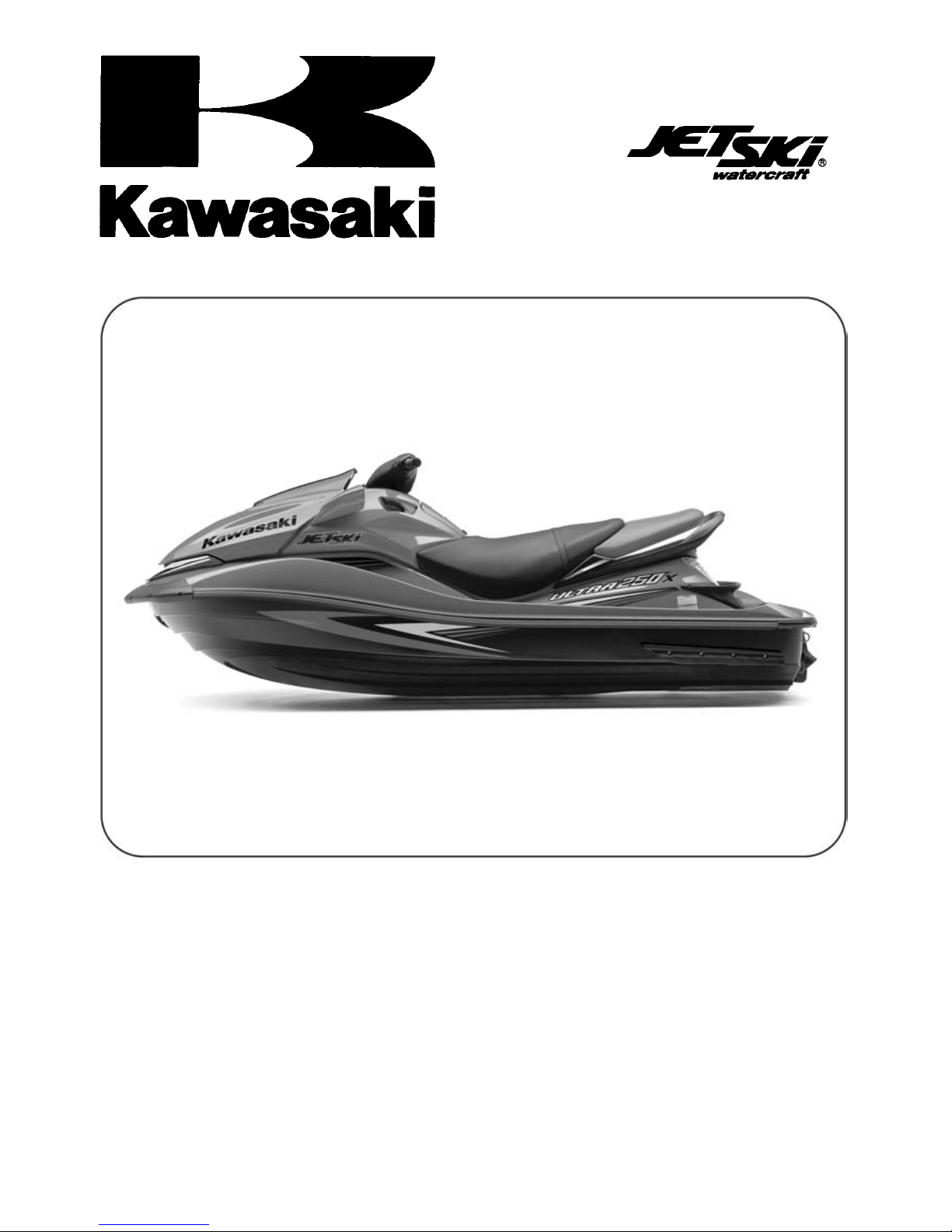
ULTRA 250X
JET SKI
Service Manual
®
Watercraft
Page 2
is a trademark of Kawasaki Heavy Industries, Ltd. registered in U.S.A., Japan,
Austria, Benelux, Sweden, Denmark, Switzerland, France, Canada, Finland, Norway, Greece, Italy,
U.K., Portugal, Thailand, and Taiwan.
KAWASAKI JET SKI®is a trademark of Kawasaki Heavy Industries, Ltd. registered in Australia.
Page 3
Quick Reference Guide
General Information 1 j
Periodic Maintenance 2 j
Fuel System (DFI) 3 j
Engine Lubrication System 4 j
Exhaust System 5 j
Engine Top End 6 j
Engine Removal/Installation 7 j
Engine Bottom End 8 j
Cooling and Bilge Systems 9 j
This quick reference guide will assist
you in locating a desired topic or procedure.
•Bend the pages back to match the
black tab of the desired chapter number with the black tab on the edge at
each table of contents page.
•Refer to the sectional table of contents
for the exact pages to locate the specific topic required.
Drive System 10 j
Pump and Impeller 11 j
Steering 12 j
Hull/Engine Hood 13 j
Electrical System 14 j
Storage 15 j
Appendix 16 j
Page 4

Page 5
ULTRA 250X
®
JET SKI
Watercraft
Service Manual
All rights reserved. No parts of this publication may be reproduced, stored in a retrieval system, or
transmitted in any form or by any means, electronic mechanical photocopying, recording or otherwise,
without the prior written permission of Quality Assurance Division/Consumer Products and Machinery
Company/Kawasaki Heavy Industries, Ltd., Japan.
No liability can be accepted for any inaccuracies or omissions in this publication, although every possible
care has been taken to make it as complete and accurate as possible.
The right is reserved to make changes at any time without prior notice and without incurring an obligation
to make such changes to products manufactured previously. See your JET SKI
latest information on product improvements incorporated after this publication.
All information contained in this publication is based on the latest product information available at the time
of publication. Illustrations and photographs in this publication are intended for reference use only and may
not depict actual model component parts.
®
watercraft dealer for the
© 2006 Kawasaki Heavy Industries, Ltd. Second Edition (1):Oct. 4, 2007 (K)
Page 6
LIST OF ABBREVIATIONS
A ampere(s) lb pound(s)
ABDC after bottom dead center
AC
ATDC after top dead center
BBDC before bottom dead center Pa pascal(s)
BDC bottom dead center PS horsepower
BTDC before top dead center psi pound(s) per square inch
°C degree(s) Celsius r revolution
DC direct current rpm revolution(s) perminute
F farad(s) TDC top dead center
°F degree(s) Fahrenheit TIR total indicator reading
ft foot, feet Vvolt(s)
ggram(s) W watt(s)
h
L
alternating current
hour(s)
liter(s)
m
min
N
Ω ohm(s)
meter(s)
minute(s)
newton(s)
COUN
AT Austria EUR Europe
CA Cana
CAL California US United States
CH Switzerland WVTA Whole Vehicle Type Approval
DE Germany
da
TRY AND AREA CODES
GB
United Kingdom
Page 7
MAINTENANCE AND ADJUSTMENTS
Maintenance, replacement, or repair of the emission control devices and systems may
be performed by any marine Sl engine repair establishment or individual.
EMISSION CONTROL INFORMATION
Fuel Information
THIS ENGINE IS CERTIFIED TO OPERATE ON UNLEADED PREMIUM GRADE GASOLINE
ONLY.
A minimum of 90 octane of the antiknock index is recommended. The antiknock index is posted
on service station pumps.
Emission Control Information
To protect the environment in which we all live, Kawasaki has incorporated an exhaust emission control system in compliance with applicable regulations of the United States Environmental
Protection Agency.
Exhaust Emission Control System
This system reduces the amount of pollutants discharged into the atmosphere by the exhaust
of this engine. The fuel, ignition and exhaust systems of this engine have been carefully designed and constructed to ensure an efficient engine with low exhaust pollutant levels.
Maintenance
Proper maintenance and repair are necessary to ensure that watercraft will continue to have
low emission levels. This Service Manual contains those maintenance and repair recommendations for this engine. Those items identified by the Periodic Maintenance Chart are necessary
to ensure compliance with the applicable standards.
Tampering with Emission Control System Prohibited
Federal law prohibits the following acts or the causing thereof: (1) the removal or rendering
inoperative by any person other than for purposes of maintenance, repair, or replacement, of
any device or element of design incorporated into any new engine for the purposes of emission
control prior to its sale or delivery to the ultimate purchaser or while it is in use, or (2) the use
of the engine after such device or element of design has been removed or rendered inoperative
by any person.
Among those acts presumed to constitute tampering are the acts listed below:
Do not tamper with the original emission related parts.
* Digital Transistor Ignition System
* Fuel Pump
* Spark Plugs
* Throttle Body and Internal Parts
* Fuel Injectors
*ECU
* Supercharger with intercooler & relief-valves
Page 8
Foreword
This manual is designed primarily for use by
trained mechanics in a properly equipped shop.
However, it contains enough detail and basic information to make it useful to the owner who desires to perform his own basic maintenance and
repair work. A basic knowledge of mechanics,
the proper use of tools, and workshop procedures must be understood in order to carry out
maintenance and repair satisfactorily. Whenever the owner has insufficient experience or
doubts his ability to do the work, all adjustments, maintenance, and repair should be carried out only by qualified mechanics.
In order to perform the work efficiently and
to avoid costly mistakes, read the text, thoroughly familiarize yourself with the procedures
before starting work, and then do the work carefully in a clean area. Whenever special tools or
equipment are specified, do not use makeshift
tools or equipment. Precision measurements
can only be made if the proper instruments are
used, and the use of substitute tools may adversely affect safe operation.
For the duration of the warranty period,
we recommend that all repairs and scheduled
maintenance be performed in accordance with
this service manual. Any owner maintenance or
repair procedure not performed in accordance
with this manual may void the warranty.
To get the longest life out of your JET SKI
watercraft:
Follow the Periodic Maintenance Chart in the
•
Service Manual.
Be alert for problems and non-scheduled
•
maintenance.
Use proper tools and genuine Kawasaki JET
•
®
SKI
watercraft parts. Special tools, gauges,
and testers that are necessary when servicing Kawasaki JET SKI
duced by the Service Manual. Genuine parts
provided as spare parts are listed in the Parts
Catalog.
®
watercraft are intro-
Follow the procedures in this manual care-
•
fully. Don’t take shortcuts.
Remember to keep complete records of main-
•
tenance and repair with dates and any new
parts installed.
How to Use This Manual
In this manual, the product is divided into
its major systems and these systems make up
the manual’s chapters. The Quick Reference
Guide shows you all of the product’s system
and assists in locating their chapters. Each
chapter in turn has its own comprehensive Table of Contents.
For example, if you want ignition coil information, use the Quick Reference Guide to locate
the Electrical System chapter. Then, use the
Table of Contents on the first page of the chapter to find the Ignition Coil section.
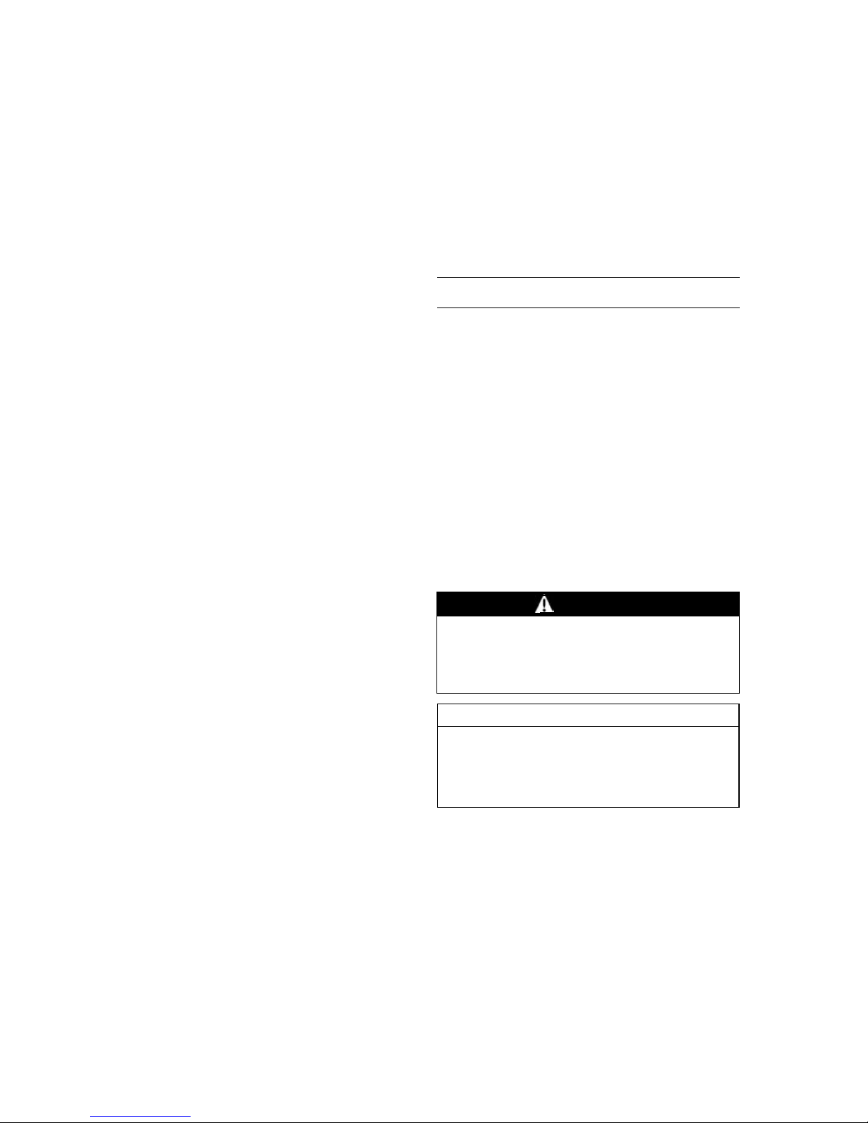
Whenever you see these WARNING and
CAUTION symbols, heed their instructions!
Always follow safe operating and maintenance
practices.
WARNING
This warning symbol identifies special
instructions or procedures which, if not
correctly followed, could result in per-
®
sonal injury, or loss of life.
CAUTION
This caution symbol identifies special
instructions or procedures which, if not
strictly observed, could result in dam-
age to or destruction of equipment.
This manual contains four more symbols (in
addition to WARNING and CAUTION) which will
help you distinguish different types of information.
Page 9

NOTE
This note symbol indicates points of par-
○
ticular interest for more efficient and convenient operation.
Indicates a procedural step or work to be
•
done.
Indicates a procedural sub-step or how to do
○
the work of the procedural step it follows. It
also precedes the text of a NOTE.
Indicates a conditional step or what action to
take based on the results of the test or inspection in the procedural step or sub-step it fol-
lows.
In most chapters an exploded view illustration
of the system components follows the Table of
Contents. In these illustrations you will find the
instructions indicating which parts require specified tightening torque, oil, grease or a locking
agent during assembly.
This model, JT1500B, is mounted with a four
-stroke engine with supercharger.
When the JET SKI
and swamped, the four-stroke engine needs
special care and systematic procedure for recovery compared with the two-stroke engine.
Therefore in this manual, such procedures,
which are not shown in SMs for two-stroke
engines, are explained thoroughly to cope with
the cases.
Refer to the section, After submerging in
Chapter 9, Cooling and Bilge Systems for the
summary and detailed procedures.
®
watercraft is submerged
Page 10

Page 11

GENERAL INFORMATION 1-1
General Information
Table of Contents
Before Servicing ..................................................................................................................... 1-2
Model Identification................................................................................................................. 1-10
General Specifications............................................................................................................ 1-11
Unit Conversion Table ............................................................................................................ 1-13
1
Page 12
1-2 GENERAL INFORMATION
Before Servicing
Before starting to perform an inspection service or carry out a disassembly and reassembly operation on watercraft, read the precautions given below. To facilitate actual operations, notes, illustrations, photographs, cautions, and detailed descriptions have been included in each chapter wherever
necessary. This section explains the items that require particular attention during the removal and
reinstallation or disassembly and reassembly of general parts.
Especially note the following:
Kawasaki Diagnostic S ystem (KDS) Software
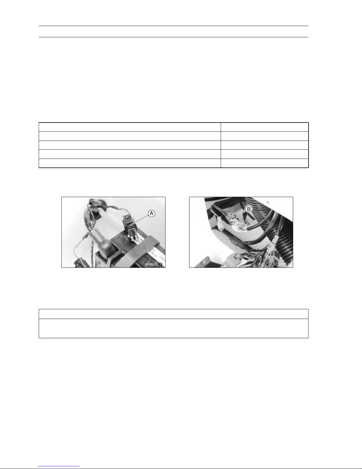
KDS software that runs on Windows personal computer (PC) will be available as a diagnostic tool
for watercraft with Kawasaki DFI system.
You need the following items to use the KDS.
Item
KDS Software Version 2.□ (CD-ROM, Updated Version) 57001-1503
Signal Converter 57001-1504
Communication Cable and Cable Adapter 57001-1470
KDS Adapter Cable 57001-1696
The connectors for the communication cable and KDS adapter cable are located in the front.
Connect the communication cable to the KDS connector (4-pin) [A] and the KDS adapter cable
between the ignition switch (immobilizer amplifier) lead connectors (6-pin) [B].
P/No.
Adjustments
Adjustments shall be made in accordance with the Periodic Maintenance Chart or whenever troubleshooting or presence of symptoms indicate that adjustments may be required. Whenever running
of the engine is required during maintenance it is best to have the watercraft in water.
CAUTION
Do not run the engine without cooling water supply for more than 15 seconds, especially
in high revolutionary speed or severe engine and exhaust system damage will occur.
Auxiliary Cooling
An auxiliary cooling supply may be used if the watercraft cannot be operated in water during adjustments. If possible, always operate the watercraft in water rather than use an auxiliary cooling supply.
Page 13
Before Servicing
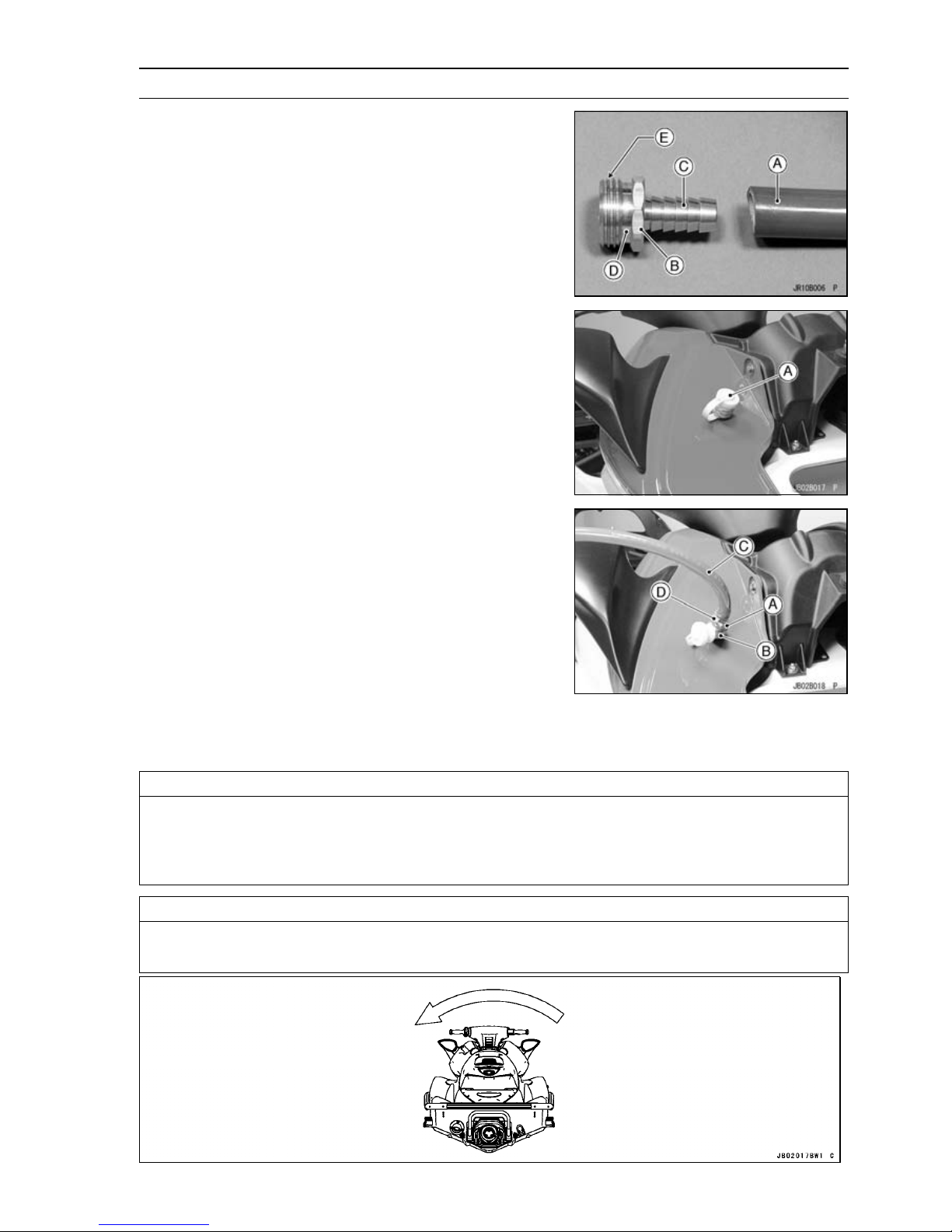
Obtain a standard garden hose [A] and a garden hose
•
adapter [B] as shown.
C: Garden Hose Fitting of Adapter
D: Flushing Fitting of Adapter
E: Thread: Rp 3/4
Optional part (P/No. 92005-3746) is available as a garden
○
hose adapter.
Open the front storage compartment cover.
•
Remove the flushing cap [A] on the brim of the storage
•
compartment.
GENERAL INFORMATION 1-3
Screw a garden hose adapter [A] onto the flushing fitting
•
[B].
Attach a garden hose [C] to a garden hose adapter and
•
secure the hose clamp [D].
Attach the garden hose to a faucet. Do not turn on the water until the engine is running and turn it
•
off immediately when the engine stops. The engine requires 2.4 L/min (2.5 qts/min) at 1 800 rpm
and 7.0 L/min (7.4 qts/min) at 6 000 rpm.
CAUTION
Insufficient cooling supply will cause the engine and/or exhaust system to overheat and
severe damage will occur. Excessive cooling supply may kill the engine and flood the cylinders, causing hydraulic lock. Hydraulic lock will cause severe damage to the engine. If the
engine dies while using an auxiliary cooling supply, the water must be shut off immediately.
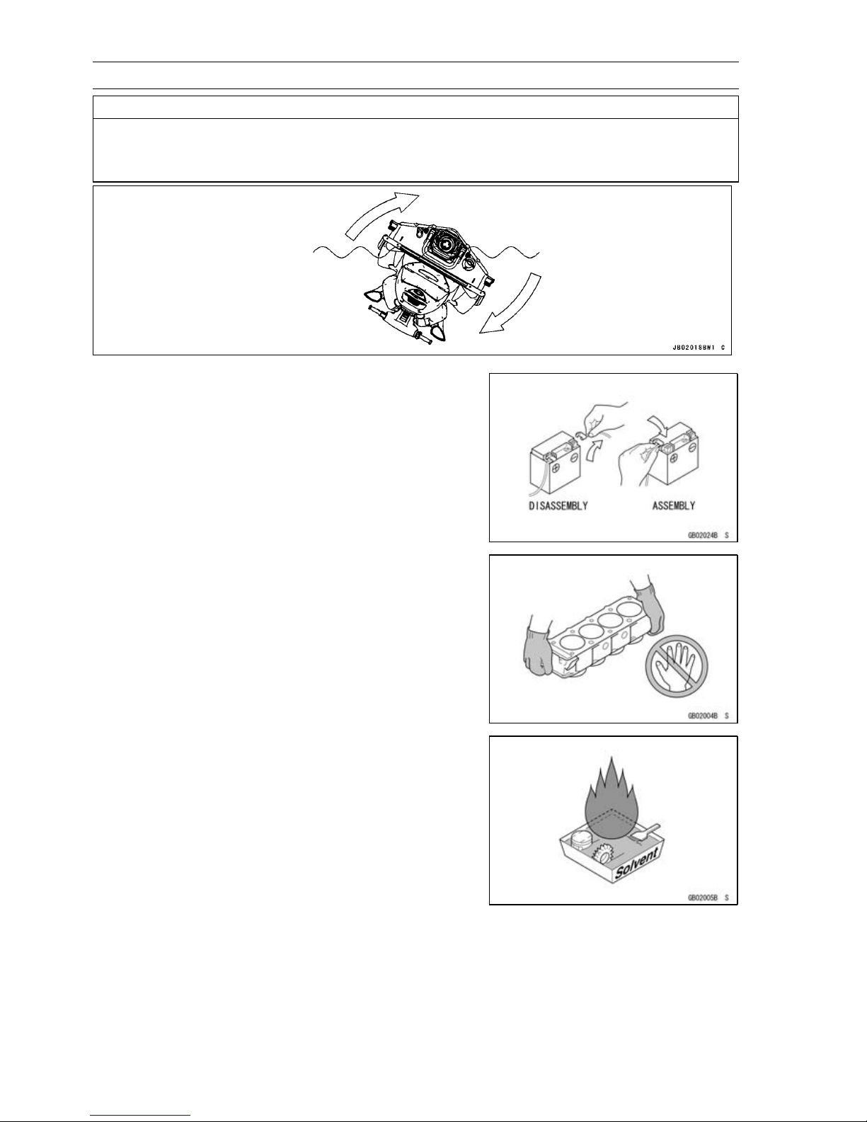
CAUTION
Always turn the boat on its left side. Rolling to the right side can cause water in the exhaust
system to run into the engine, with possible engine damage.
Page 14
1-4 GENERAL INFORMATION
Before Servicing
CAUTION
Turn the capsized boat clockwise so that the port side always faces downward. Turning
counterclockwise can cause water in the exhaust system to run into the engine, with pos-
sible engine damage.
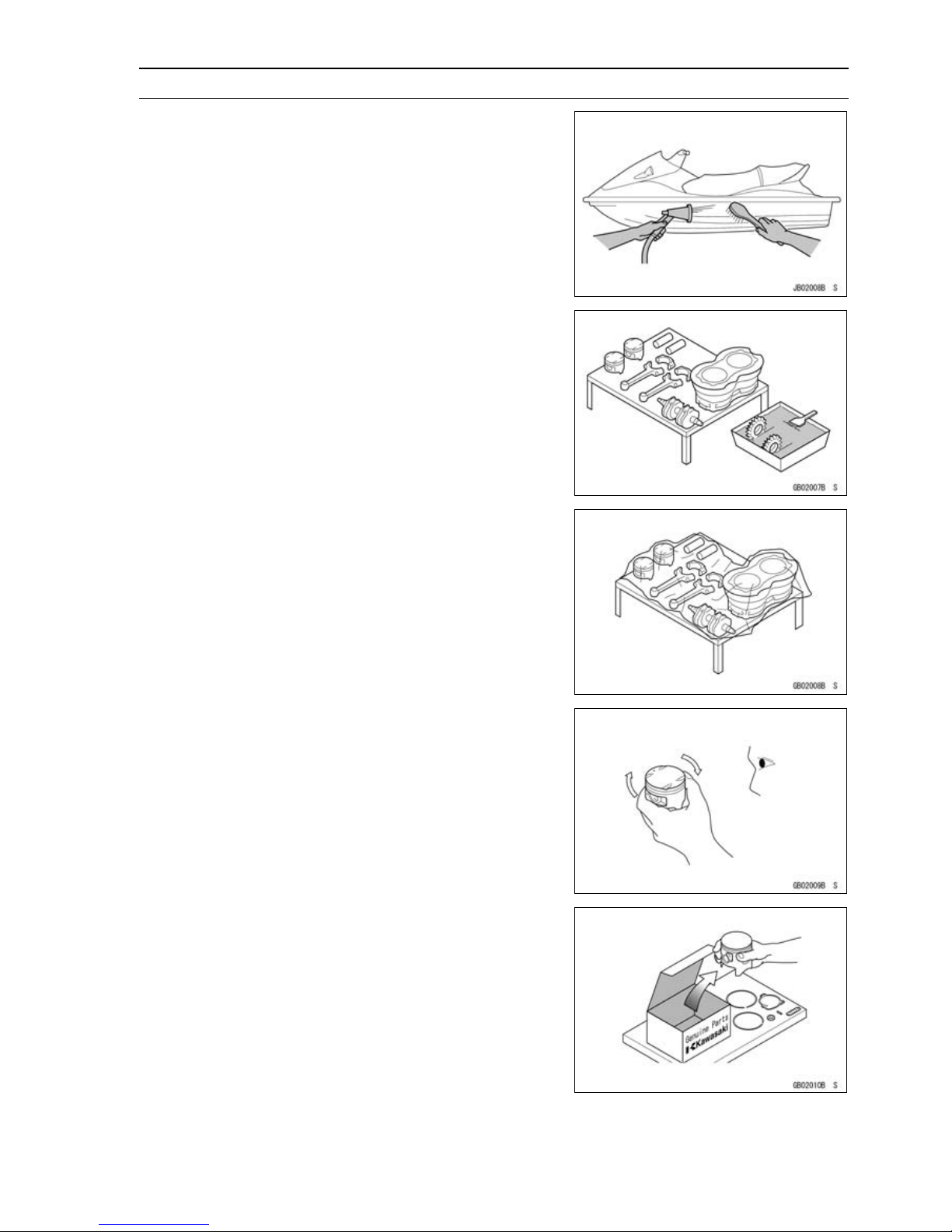
Battery Ground
Before completing any service on the watercraft, disconnect the battery wires from the battery to prevent the engine
from accidentally turning over. Disconnect the ground wire
(–) first and then the positive (+). When completed with the
service, first connect the positive (+) wire to the positive (+)
terminal of the battery then the negative (–) wire to the negative terminal.
Edges of Parts
Lift large or heavy parts wearing gloves to prevent injury
from possible sharp edges on the parts.
Solvent
Use a high flush point solvent when cleaning parts. High
flush point solvent should be used according to directions
of the solvent manufacturer.
Page 15
Before Servicing
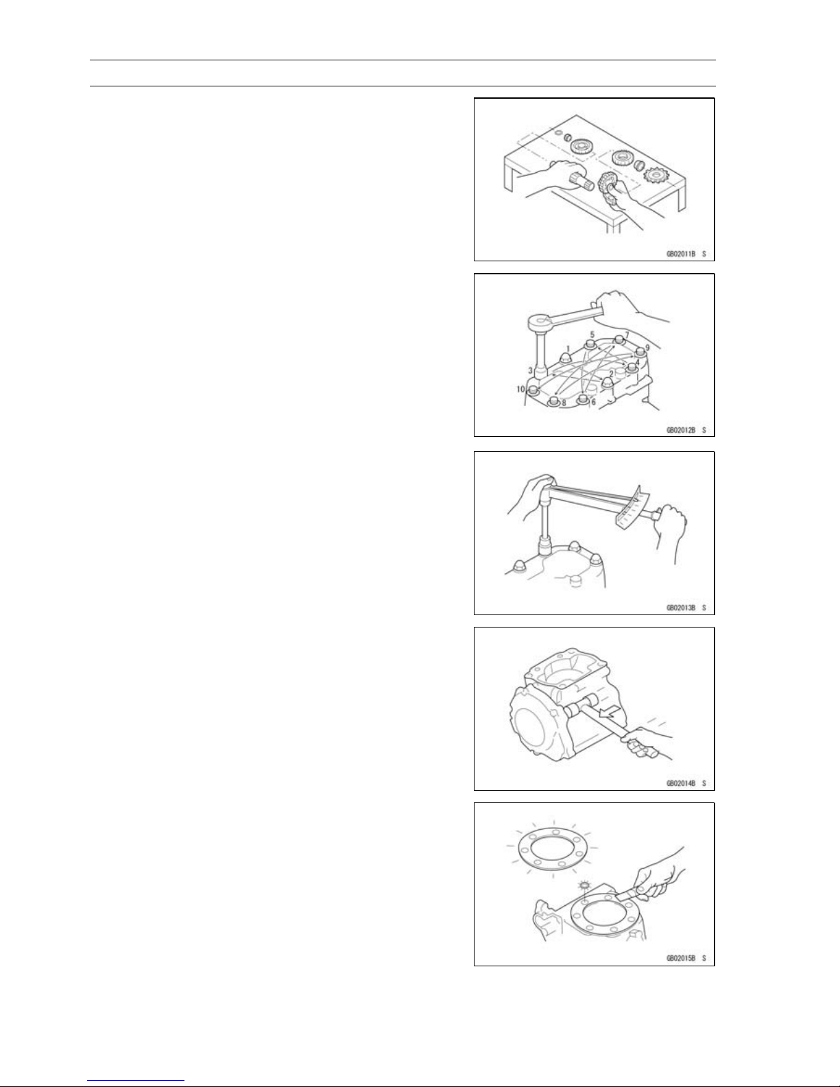
Cleaning Watercraft before Disassembly
Clean the watercraft thoroughly before disassembly. Dirt
or other foreign materials entering into sealed areas during
watercraft disassembly can cause excessive wear and decrease performance of the watercraft.
Arrangement and Cleaning of Re moved Parts
Disassembled parts are easy to confuse. Arrange the
parts according to the order the parts were disassembled
and clean the parts in order prior to assembly.
GENERAL INFORMATION 1-5
Storage of Removed Parts
After all the parts including subassembly parts have been
cleaned, store the parts in a clean area. Put a clean cloth
or plastic sheet over the parts to protect from any foreign
materials that may collect before re-assembly.
Inspection
Reuse of worn or damaged parts may lead to serious accident. Visually inspect removed parts for corrosion, discoloration, or other damage. Refer to the appropriate sections
of this manual for service limits on individual parts. Replace
the parts if any damage has been found or if the part is beyond its service limit.
Replacement Parts
Replacement Parts must be KAWASAKI genuine or
recommended by KAWASAKI. Gaskets, O-rings, Oil seals,
Grease seals, circlips or cotter pins must be replaced with
new ones whenever disassembled.
Page 16
1-6 GENERAL INFORMATION
Before Servicing
Assembly Order
In most cases assembly order is the reverse of disassembly, however, if assembly order is provided in this Service
Manual, follow the procedures given.
Tightening Sequence
Generally, when installing a part with several bolts, nuts,
or screws, start them all in their holes and tighten them to
a snug fit. Then tighten them according to the specified sequence to prevent case warpage or deformation which can
lead to malfunction. Conversely when loosening the bolts,
nuts, or screws, first loosen all of them by about a quarter turn and then remove them. If the specified tightening
sequence is not indicated, tighten the fasteners alternating
diagonally.
Tightening Torque
Incorrect torque applied to a bolt, nut, or screw may
lead to serious damage. Tighten fasteners to the specified
torque using a good quality torque wrench.
Force
Use common sense during disassembly and assembly,
excessive force can cause expensive or hard to repair damage. When necessary, remove screws that have a non
-permanent locking agent applied using an impact driver.
Use a plastic-faced mallet whenever tapping is necessary.
Gasket, O-ring
Hardening, shrinkage, or damage of both gaskets
and O-rings after disassembly can reduce sealing performance. Remove old gaskets and clean the sealing
surfaces thoroughly so that no gasket material or other
material remains. Install new gaskets and replace used
O-rings when re-assembling
Page 17
Before Servicing
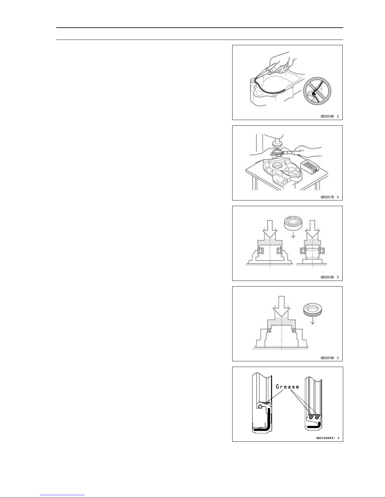
Liquid Gasket, Locking Agent
For applications that require Liquid Gasket or a Locking
agent, clean the surfaces so that no oil residue remains before applying liquid gasket or locking agent. Do not apply
them excessively. Excessive application can clog oil passages and cause serious damage.
Press
For items such as bearings or oil seals that must be
pressed into place, apply small amount of oil to the contact area. Be sure to maintain proper alignment and use
smooth movements when installing.
GENERAL INFORMATION 1-7
Ball Bearing
Do not remove pressed ball or needle unless removal is
absolutely necessary. Replace with new ones whenever
removed. Press bearings with the manufacturer and size
marks facing out. Press the bearing into place by putting
pressure on the correct bearing race as shown.
Pressing the incorrect race can cause pressure between
the inner and outer race and result in bearing damage.
Oil Seal, Grease Seal
Do not remove pressed oil or grease seals unless removal
is necessary. Replace with new ones whenever removed.
Press new oil seals with manufacture and size marks facing
out. Make sure the seal is aligned properly when installing.
Apply specified grease to the lip of seal before installing
the seal.
Page 18
1-8 GENERAL INFORMATION
Before Servicing
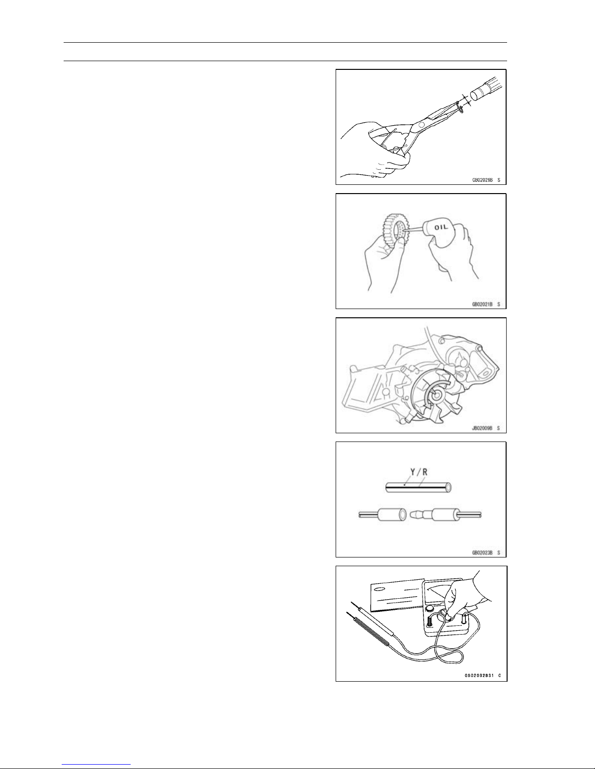
Circlips, Cotter Pins
Replace circlips or cotter pins that were removed with new
ones. Take care not to open the c lip excessively when installing to prevent deformation.
Lubrication
It is important to lubricate rotating or s liding parts during
assembly to minimize wear during initial operation. Lubrication points are called out throughout this manual, apply
the specific oil or grease as specified.
Direction of Engine Rotation
When rotating the crankshaft, by hand, the free play
amount of rotating direction will affect the adjustment. Rotate the crankshaft to positive direction (counter-clockwise
viewed from stern sinde).
Electrical Wires
A two-color wire is identified first by the primary color and
then the s tripe c olor. Unless instructed otherwise, electrical
wires must be connected to those of the same color.
Instrument
Use a meter that has enough accuracy for an accurate
measurement. Read the manufacture’s instructions thoroughly before using the meter. Incorrect values may lead
to improper adjustments.
Page 19
Before Servicing
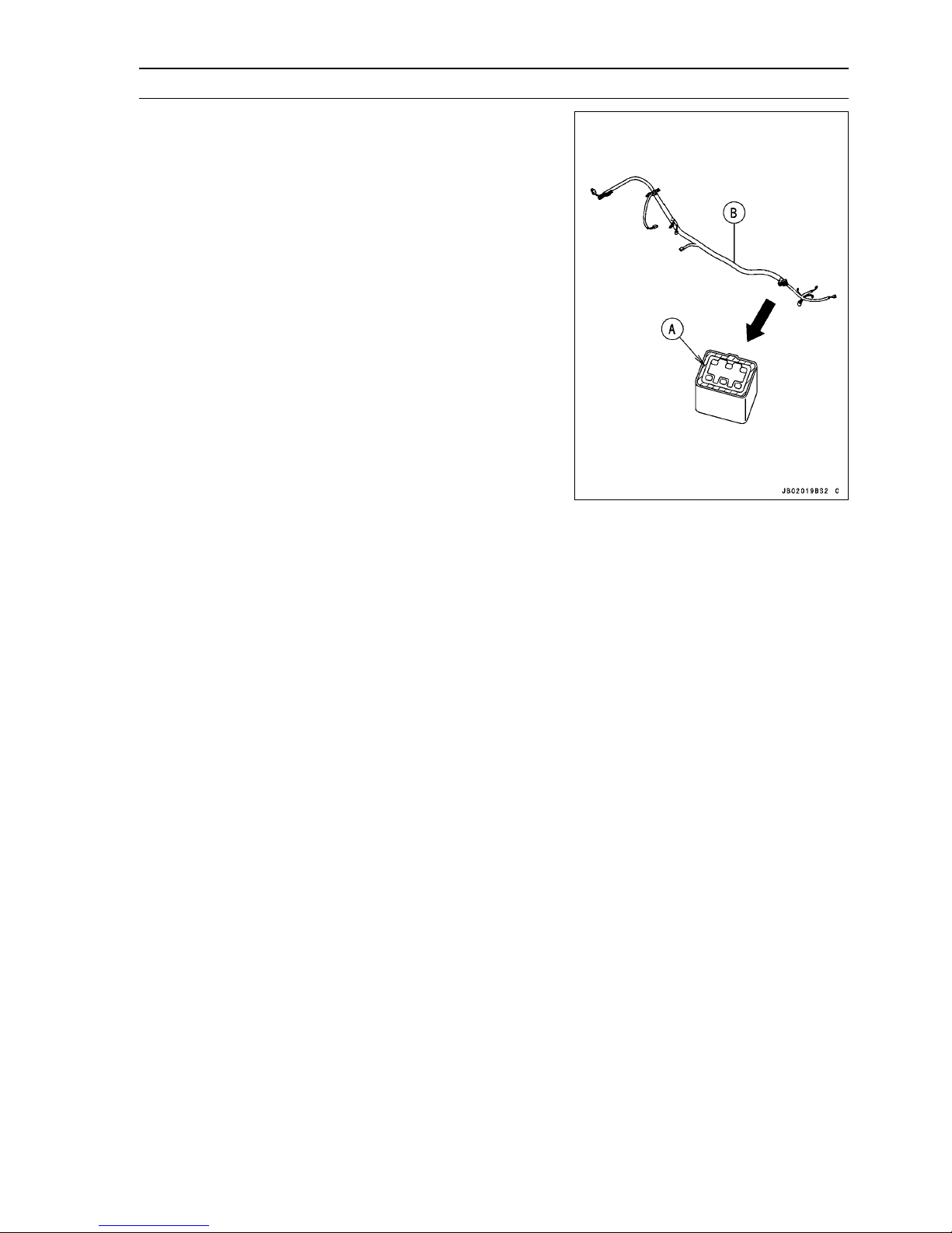
Harness Connector
Apply grease [A] on all connectors of harness [B] for water
resistance. Do not apply grease on the only connector of
inlet air pressure sensor.
GENERAL INFORMATION 1-9
Page 20
1-10 GENERAL INFORMATION
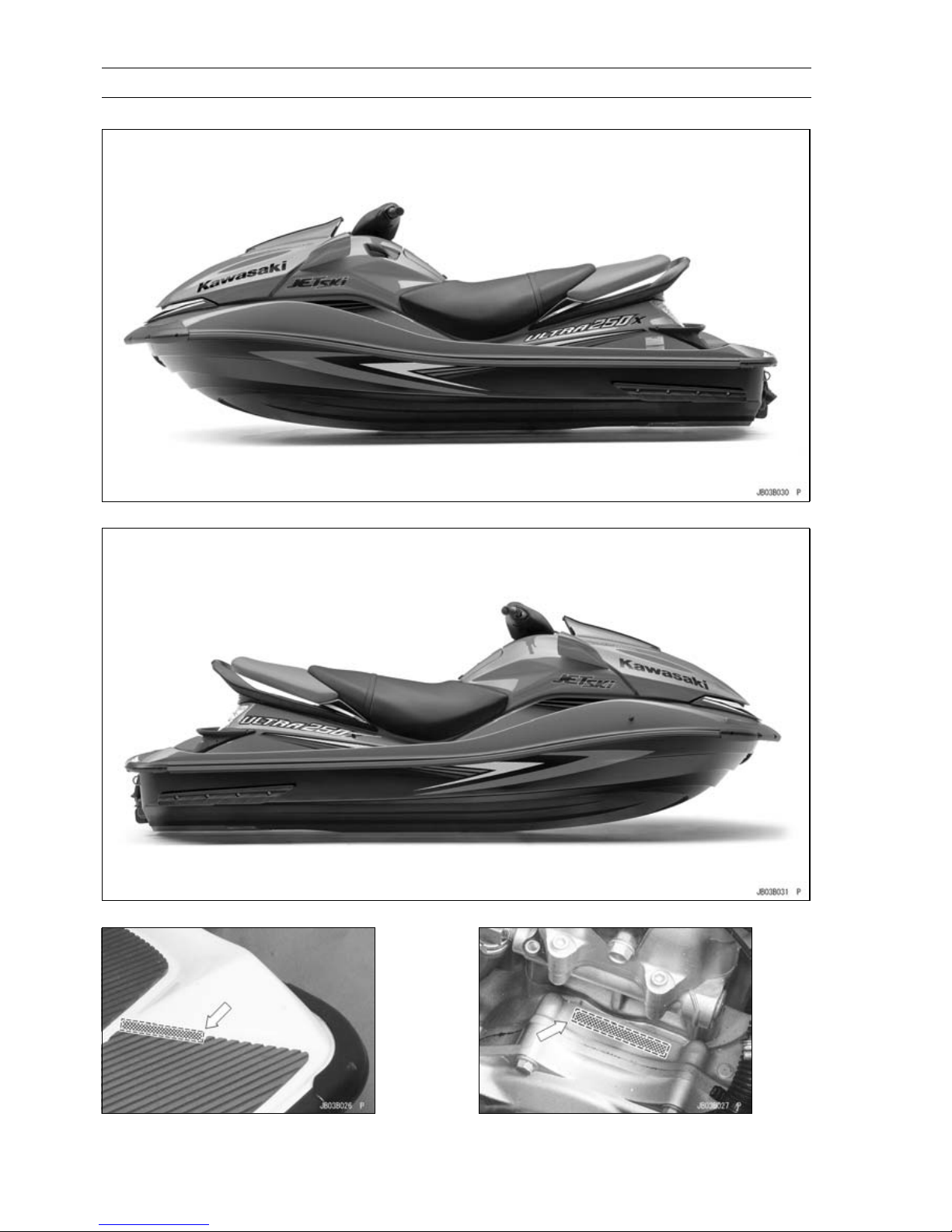
Model Identification
JT1500B7F Left Side View
JT1500B7F Right Side View
Hull Identification Number (HIN) Engine Number
Page 21
GENERAL INFORMATION 1-11
General Specifications
Items JT1500B7F ∼
Engine
Type
Displacement
Bore and Stroke 83 × 69.2 mm (3.27 × 2.72 in.)
Compression Ratio 7.8 : 1
Maximum Horsepower 184 kW (250 PS) @7 750 r/min (rpm)
Maximum Torque 237 N·m (24.2 kgf·m, 174.8 ft·lb) @6 500 r/min (rpm)
Ignition System Digital transistor
Lubrication System Forced lubrication (semi-dry sump)
Carburetion System FI (fuel injection) MIKUNI AC 60 × 1
Starting System Electric starter
Cylinder Numbering Method Front (bow) to rear (stern), 1-2-3-4
Firing Order 1-2-4-3
Valve Timing:
Inlet:
Open 15° BTDC
Close 65° ABDC
Duration 260°
Exhaust:
Open 73.5° BBDC
Close 8.5° ATDC
Duration
Tuning Specifications
Spark plug:
Type NGK PMR9B
Gap 0.6 ∼ 0.7 mm (0.024 ∼ 0.028 in.)
Ignition Timing 0° ATDC @1 300 r/min ∼ 8° BTDC @3 000 r/min (rpm)
Idle Speed 1 300 ±100 r/min (rpm) -in water
Compression Pressure 1190∼ 1799kPa(12.1∼ 18.3 kgf/cm², 173 ∼ 261 psi) @430
Drive System
Coupling Direct drive from engine
Jet Pump:
Type Axial flow single stage
Thrust 6 780 N (692 kgf, 1 524 lb)
Steering Steerable nozzle
Braking Water drag
Performance
†Minimum Turning Radius
†Fuel Consumption 74.5 L/h (19.7 US gal/h) @full throttle
†Cruising Range 105 km (65.2 mile) @full throttle 59 minutes (3 person)
Dimensions
Overall Length 3 370 mm (132.7 in.)
4-stroke, DOHC, 4-cylinder, water cooled
1 498 cm³ (91.4 cu in.)
262°
1 300 ±100 r/min (rpm) -out of water
r/min (rpm)
4.0 m (13.1 ft)
Page 22
1-12 GENERAL INFORMATION
General Specifications
Items JT1500B7F ∼
Overall Width 1195mm(47.0in.)
Overall Height 1150mm(45.3in.)
Dry Weight:
JT1500B7F 416 kg (917 lb)
JT1500B8F 410 kg (904 lb)
Fuel Tank Capacity 78 L (20.6 US gal)
Engine Oil
Type
Viscosity SAE 10W-40
Capacity 5.0 L (5.3 US qt)
Electrical Equipment
Battery 12 V 18 Ah
Maximum Generator Output 16 A @14 V
†: This information shown here represents resul ts under controlled conditions, and the information
may not be correct under other conditions.
API SE, SF or SG
API SH, SJ or SL with JASO MA
Specifications subject to change without notice, and may not apply to every country.
Page 23
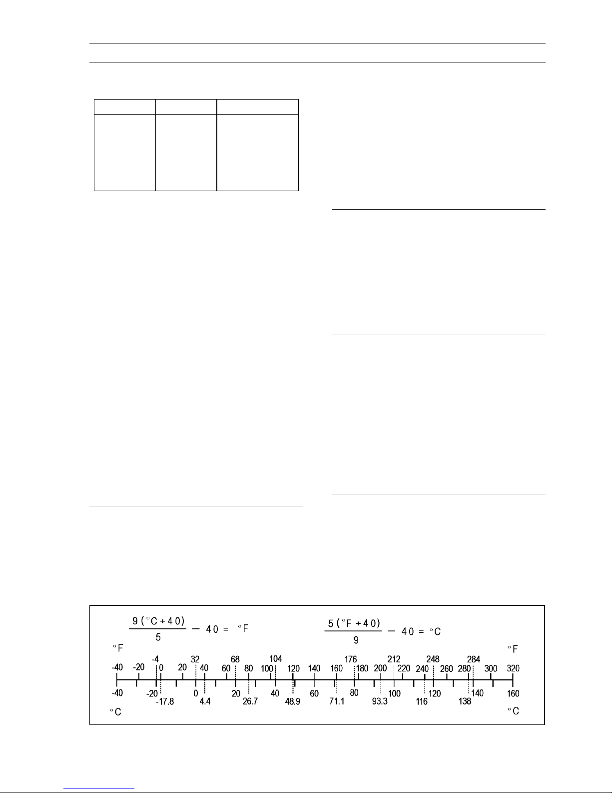
Unit Conversion Table
GENERAL INFORMATION 1-13
Prefixes for Units
Prefix Symbol
mega M × 1 000 000
kilo k ×1000
centi c ×0.01
milli m × 0.001
micro µ × 0.000001
Power
Units of Mass
kg ×2.205=lb
g × 0.03527 = oz
Units of Volume
L × 0.2642 = gal (US)
L × 0.2200 = gal (imp)
L × 1.057 = qt (US)
L × 0.8799 =
L×2.113=
L × 1.816 = pint (imp)
mL × 0.03381 = oz (US)
mL × 0.02816 = oz (imp)
mL × 0.06102 = cu in
qt (imp)
pint (US)
Units of Length
km × 0.6214 = mile
m × 3.281 = ft
mm × 0.03937 = in.
Units of Torque
N·m × 0.1020 = kgf·m
N·m × 0.7376 = ft·lb
N·m × 8.851 = in·lb
kgf·m × 9.807 = N·m
kgf·m × 7.233 = ft·lb
kgf·m × 86.80 = in·lb
Units of Pressure
kPa × 0.01020 = kgf/cm²
kPa × 0.1450 = psi
kPa × 0.7501 = cmHg
kgf/cm² × 98.07 = kPa
kgf/cm² × 14.22 = psi
cmHg×1.333=kPa
Units of Speed
km/h
× 0.6214 = mph
Units of Force
N × 0.1020 = kg
N × 0.2248 = lb
kg ×9.807=N
kg ×2.205=lb
Units of Temperature
Units of Power
kW ×1.360=PS
kW ×1.341=HP
PS
PS × 0.9863 = HP
× 0.7355 = kW
Page 24

Page 25

PERIODIC MAINTENANCE 2-1
Periodic Maintenance
Table of Contents
Periodic Maintenance Chart ................................................................................................... 2-2
Torque and Locking Agent...................................................................................................... 2-4
Specifications ......................................................................................................................... 2-10
Special Tools and Sealant ...................................................................................................... 2-11
Periodic Maintenance Procedures.......................................................................................... 2-12
Fuel System......................................................................................................................... 2-12
Throttle Control System Inspection ................................................................................... 2-12
Air Box Drain Cap Inspection and Cleaning...................................................................... 2-12
Supercharger Drive Belt for Wear/Damage and Belt Tension Inspection ......................... 2-13
Supercharger Gear Oil Level Inspection........................................................................... 2-15
Fuel Vent Check Valve Inspection .................................................................................... 2-16
Fuel Pump Screen Cleaning ............................................................................................. 2-16
Throttle Shaft Spring Inspection........................................................................................ 2-17
Engine Lubrication System.................................................................................................. 2-17
Engine Oil Change............................................................................................................ 2-17
Oil Filter Replacement ...................................................................................................... 2-18
Engine Top End ................................................................................................................... 2-19
Air Suction Valve Inspection (JT1500B7F Model)............................................................. 2-19
Valve Clearance Inspection .............................................................................................. 2-19
Engine Mounting Bolts Inspection and Tightness ............................................................. 2-24
Engine Bottom End.............................................................................................................. 2-24
Coupling Damper Inspection............................................................................................. 2-24
Cooling and Bilge Systems .................................................................................................. 2-25
Cooling System Flushing .................................................................................................. 2-25
Bilge System Flushing ...................................................................................................... 2-26
Pump and Impeller............................................................................................................... 2-27
Impeller Inspection............................................................................................................ 2-27
Steering ............................................................................................................................... 2-27
Steering Cable/Shift Cable Inspection .............................................................................. 2-27
Handlebar Pivot Lubrication.............................................................................................. 2-28
Hull/Engine Hood.................................................................................................................2-28
Drain Plug Inspection........................................................................................................ 2-28
Electrical System ................................................................................................................. 2-29
Battery Charging Condition Inspection ............................................................................. 2-29
Battery Terminals Inspection............................................................................................. 2-29
Spark Plug Inspection....................................................................................................... 2-29
Lubrication ........................................................................................................................... 2-30
All Hoses, Hose Clamps, Nuts, Bolts and Fasteners Check ............................................... 2-33
Nuts, Bolts, and Fasteners Tightness Inspection.............................................................. 2-33
Hose and Hose Connect Inspection ................................................................................. 2-33
Rubber Strap Inspection ................................................................................................... 2-35
2
Page 26
2-2 PERIODIC MAINTENANCE
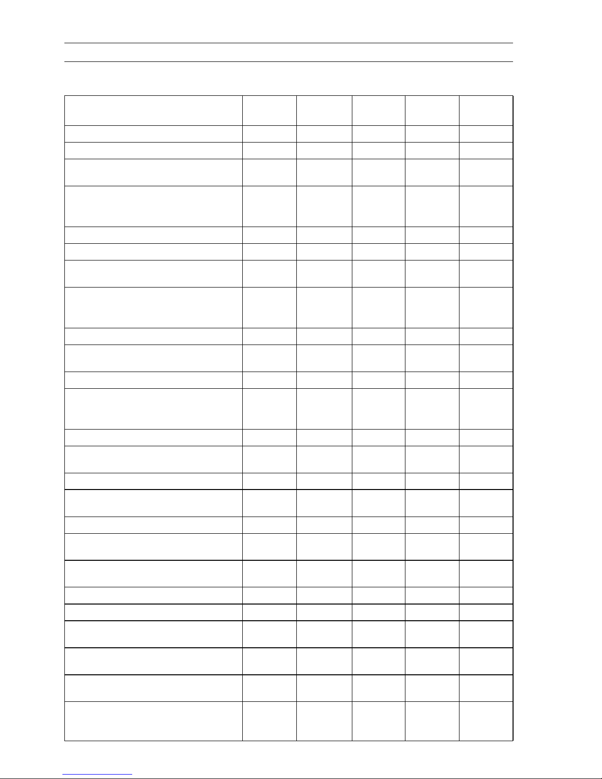
Periodic Maintenance Chart
The scheduled maintenance must be done in accordance with this chart to keep the watercraft in
good running condition. The initial maintenance is vitally important and must not be neglected.
Frequency
Description
Inspect throttle control system (e)
Inspect/clean air box drain caps
Inspect supercharger drive belt for
wear/damage and belt tension
Initial 10
Hours
• •
Every 25
Hours
•
•
Every 50
Hours
Every 100
Hours
Reference
2-12
2-12
2-13
Inspect supercharger gear oil level
(refill if necessary)
Inspect fuel vent check valve
Clean fuel pump screen (e)
Inspect throttle shaft spring (replace
throttle body if necessary) (e)
Replace engine oil
Replace engine oil filter
Check air suction valve (JT1500B7F
Model)
Inspect/adjust valve clearance (e)
Inspect/tighten en
Inspect/replace coupling damper
Flush cooling system (after each use
in salt water)
Flush bilge line and filter
Inspect impeller blades for damage
(remove)
Inspect steering cable/shift cable
Lubricate handlebar pivot
(disassemble)
Inspect hull drain screws (replace if
necessary)
Inspect battery charging condition
Inspect battery terminals
Inspect spark plugs (replace if
necessary) (e)
Lubricate throttle cable fitting at throttle
body
Lubricate throttle cable and throttle
fitting at thro
Lubricate steering cable/shift cable
ball joints and steering nozzle/reverse
bucket pivots
gine mounting bolts
ttle case
•
(or every
year)
•
•
•
•
(or every
year)
•
•
•
•
(or every
year)
•
•
•
•
•
•
•
•
•
•
•
•
•
2-15
2-16
2-16
2-17
2-17
2-18
2-19
2-19
2-24
2-24
2-25
2-26
2-27
2-27
2-28
2-28
2-29
2-29
2-30
2-30
2-31
2-31
Page 27
Periodic Maintenance Chart
PERIODIC MAINTENANCE 2-3
Frequency
Description
Check all hoses, hose clamps, nuts,
bolts, and fasteners
(e): Emission Related Items
Initial 10
Hours
• •
Every 25
Hours
Every 50
Hours
Every 100
Hours
Reference
2-33
Page 28
2-4 PERIODIC MAINTENANCE
Torque and Locking Agent
The following table list the tightening torque for the major fasteners, and the parts requiring use of
a non-permanent locking agent or silicone sealant.
Letters used in the “Remarks” column mean:
EO: Apply oil to the threads and seating surface.
L: Apply a non-permanent locking agent (Medium Strength: Loctite 242 Equivalent).
LN: Apply a non-permanent locking agent (High Strength: Loctite 271 Equivalent).
MO: Apply molybdenum disulfide grease oil solution.
R: Replacement Part
S: Tighten the fasteners following the specified sequence.
SS: Apply silicone sealant to the threads.
Fastener
Fuel System
Vehicle-down Sensor Mounting Screws
Bracket Mounting Bolts 8.8 0.90 78 in·lb L
Inlet Manifold Mounting Bolts 25 2.5 18
Inlet Manifold Mounting Nuts 20 2.0 14
Delivery Pipe Mounting Bolts 7.8 0.80 69 in·lb
Inlet Air Pressure Sensor Bracket Bolts 8.8 0.90 78 in·lb L
Inlet Air Temperature Sensor 20 2.0 14
Throttle Body Assy Mounting Bolts 20 2.0 14
Inlet Manifold Dr
Throttle Body Assy Damper Bolts 20 2.0 78 in·lb
Crankshaft Sensor Screws 4.4 0.45 39 in·lb L
Camshaft Position Sensor Bolt 9.8 1.0 87 in·lb L
Water Temperature Sensor
Oil Temperature Sensor
ECU Mounting Bol
Relay Bolts 2.5 0.25 22 in·lb L
Throttle Sensor Mounting Screws 2.0 0.20 18 in·lb
ISC Actuator Mounting Bolts 4.9 0.50 43 in·lb
Fuse Bracket Bolt 2.5 0.25 22 in·lb L
Harness Bolts 8.8 0.90 78 in·lb L
Charging Tempe
Fuel Filler Tube Clamp Screws 2.9 0.30 26 in·lb
Fuel Pump Holder Clamp Screws 2.9 0.30 26 in·lb
Oil Separator Tank Mounting Bolts 8.8 0.90 69 in·lb L
Air Box Bracket Bolts 8.8 0.90 69 in·lb L
Air Box Bolts 8.8 0.90 69 in·lb L
Rear Supercharger Bolts 45 4.6 33
Belt Tensioner Plate Bolts 45 4.6 33
Belt Tensioner Shaft Bolt 30 3.1 22
Intake Pipe Bolts (IN/OUT) 7.8 0.80 69 in·lb
Gear Oil Level Gauge 19 1.9 14
Front Supercharger Bolts 45 4.6 33
Drain Bolt 19 1.9 14
ain P lug
ts
rature Sensor
N·m kgf·m ft·lb
1.5 0.15 13 in·lb
20 2.0 14
15 1.5 11 see text
15 1.5 11 see text
3.0 0.3 27 in·lb L
15 1.5 11
Torque
Remarks
Page 29
Torque and Locking Agent
PERIODIC MAINTENANCE 2-5
Fastener
Pulley Bolt 19 1.9 14
Belt Cover Bolts
Intercooler Plate Bolts 8.8 0.90 69 in·lb L
Intercooler Bracket Bolts 7.8 0.80 69 in·lb
Intercooler Mounting Bolts 30 3.1 22
Water Hose Joint 11 1.1 95 in·lb L
Water Hose Joint 20 2.0 14 L
Intercooler Cover Bolts
Blow off Valve Bolts
Throttle Cable Locknuts 20 2.0 14
Pulley Plate Bolts 15 1.5 11 L
Belt Tension Adjuster 3.0 0.31 27 in·lb
Engine Lubrication System
Breather Plate Bolts 7.8 0.80 69 in·lb
Oil Filler Cap
Oil Passage Plugs 20 2.0 14 L
Oil Separator Tank Mounting Bolts 4.9 0.50 43 in·lb L
Breather Case Mounting Bolts 7.8 0.80 69 in·lb
Breather Pipe Bolts 8.8 0.90 78 in·lb
Oil Passage Joints
Oil C ooler Assembly Bolts
Oil Pressure Switch 15 1.5 11 SS
Oil Passage Bolt 78 8.0 58 S
Oil Filter 18 1.8 13 EO
Oil Cooler Positioning Bolt 20 2.0 14 S
Oil Pan Bolts 7.8 0.80 69 in·lb S
Dipstick Tube Bolts 7.8 0.80 69 in·lb L, S
Oil Pump Sprocket Bolt 16 1.6 12 LN
Oil Pump Cover Bolts 7.8 0.80 69 in·lb
Oil Pressure Relief Valve 15 1.5 11 LN
Oil Pipe Bolts
Oil Pump Chain Guide Bolt
Chain Guide Spring Plate Bolt
Oil Pump Body Plug 20 2.0 14 L
Oil Pump Body Bolts 7.8 0.80 69 in·lb
Oil Screen Bolts 7.8 0.80 69 in·lb
Water Hose Joints 20 2.0 14 SS
Exhaust System
Exhaust Manifold Mounting Nuts 30 3.1 22
Exhaust Manifold Mounting Bolts 30 3.1 22
Bypass Nozzle – – – LN
Flushing Hose Joints 11 1.1 95 in·lb L
Water Temperature Sensor
N·m kgf·m ft·lb
4.9 0.50 43 in·lb L
10 1.0 89 in·lb
7.8 0.80 69 in·lb
– – – Hand-tighten
11 1.1 95 in·lb L
7.8 0.80 69 in·lb
7.8 0.80 69 in·lb
7.8 0.80 69 in·lb
7.8 0.80 69 in·lb
15 1.5 11 see chapter 3
Torque
Remarks
Page 30
2-6 PERIODIC MAINTENANCE
Torque and Locking Agent
Fastener
Exhaust Pipe Mounting Bolt (L = 150 mm) 45 4.6 33
Exhaust Pipe Mounting Bolts (L = 120 mm)
Exhaust Pipe Mounting Bolts (L = 95 mm)
Mark Plate Bolts 5.0 0.51 44 in·lb
Water Hose Joint 20 2.0 14 L
Muffler Body Bolts 35 3.6 26
Front Exhaust Tube Clamp Screws
(JT1500B7F)
Front Exhaust Tube Clamp Screws
(JT1500B8F)
Water Hose Joint 11 1.1 95 in·lb L
Rear Exhaust Tube Clamp Screws
(JT1500B8F)
Engine Top End
Air Suction Valve Cover Bolts 9.8 1.0 87 in·lb
Cylinder Head Cover Bolts 9.8 1.0 87 in·lb
Upper Camshaft Chain Guide Bolts
Camshaft Cap Bolts
Cylinder Head Bol
Cylinder Head Bolts (M11) 23 2.3 17 First, MO, S
Cylinder Head Bolts (M11) 69 7.0 51 Final, MO, S
Water Jacket Plugs 20 2.0 14 L
Cylinder Head Bolts (M6)
Engine Hook Bolts 20 2.0 14
Camshaft Position Sensor Bolt 9.8 1.0 87 in·lb L
Water Hose Joints 20 2.0 14 L
Cylinder Head Cover Plate Bolts 7.8 0.80 69 in·lb
Exhaust Side Camshaft Chain Guide Bolts
(Upper)
Exhaust Side Camshaft Chain Guide Bolts
(Lower)
Upper Camshaft Chain Guide Bolts 12 1.2 104 in·lb S
Inlet Side Camshaft Chain Guide Bolt 12 1.2 104 in·lb L
Camshaft Chain Tensioner Mounting Bolts 9.8 1.0 87 in·lb L
Camshaft Chain Tensioner Cap B olt 20 2.0 14
Camshaft Position Sensor Rotor Bolt 12 1.2 104 in·lb L
Water Hose Jo
Oil Passage Joint 11 1.1 95 in·lb L
Engine Removal/Installation
Engine Mounting Bolts 36 3.7 27 L
Engine Damper Mounting Bolts 16 1.6 12 L
Engine Bottom End
Crankshaft S
Engine Bracket Mounting Bolts 32 3.3 24 L
ts (M7)
int
ensor Cover Bolts
N·m kgf·m ft·lb
35 3.6 26
35 3.6 26
2.9 0.30 26 in·lb
4.9 0.50 43 in·lb
4.9 0.50 43 in·lb
12 1.2 104 in·lb
12 1.2 104 in·lb
20 2.0 14
12 1.2 104 in·lb
25 2.5 18
12 1.2 104 in·lb
20 2.0 14 L
7.8 0.80 69 in·lb
Torque
Remarks
S
S
S
S
Page 31
Torque and Locking Agent
PERIODIC MAINTENANCE 2-7
Fastener
Timing Rotor Bolt 20 2.0 14 L
Connecting Rod Nuts
Oil Passage Plugs
Stator Mounting Bolts 12 1.2 104 in·lb L
Grommet Cover Bolts 9.8 1.0 87 in·lb L
Magneto Cover Bolts 20 2.0 14
Output Cover Bolts 7.8 0.80 69 in·lb
Output Shaft 245 25.0 180 MO
Coupling 110 11 81
Crankcase Bolts (M10) 50 5.0 36 MO, S
Crankcase Bolts (M8) 29 3.0 22 MO, S
Crankcase Bolts (M8) 29 3.0 22 S
Crankcase Bolts (M6)
Cooling and Bilge Systems
Water Hose J oint (L Shape Type)
Water Hose Joint (Straight Shape Type) 20 2.0 14 L
Cooling Hose Clamp Screws 2.5 0.25 22 in·lb
Intercooler Bracket Bolts 7.8 0.80 69 in·lb
Intercooler Mounting Bolts 30 3.1 22
Intercooler Cover Bolts 10 1.0 89 in·lb
Intercooler Plate Bolts 8.8 0.90 69 in·lb L
Drive System
Coupling 39 4.0 29
Drive Shaft Holder Mounting Bolts 22 2.2 16 L
Pump and Impeller
Pump Bracket Mounting Bolts (2)
Pump Bracket Mounting Bolts (4)
Pump Mounting Bolts 36 3.7 27 L
Grate Mounting Bolts 9.8 1.0 87 in·lb L
Pump Cover Mounting Bolts 7.8 0.80 69 in·lb L
Impeller 98 10 72
Pump Cap Bolts 3.9 0.4 35 in·lb L
Pump Outlet Mounting Bolts 19 1.9 14 L
Steering Nozzle Pivot Bolts 19 1.9 14 L
Filter Cover Mounting Bolts 9.8 1.0 87 in·lb L
Steering Cable Joint Bolt 9.8 1.0 87 in·lb L
Steering
Handlebar Clamp Bolts
Adjustable Steering Holder Nut
Steering Neck Mounting Bolts 16 1.6 12 L
Steering Shaft Locknut 49 ∼ 59 5.0 ∼ 6.0 36 ∼ 43
Steering Holder Mounting Nuts 20 2.0 14.5 L
Throttle Case Mounting Screws 3.9 0.40 35 in·lb
N·m kgf·m ft·lb
– – –
20 2.0 14 L
12 1.2 104 in·lb
11 1.1 95 in·lb L
19 1.9 14
9.8 1.0 87 in·lb L
16 1.6 12 L
20 2.0 14.5
Torque
Remarks
MO, see text
LN, SS
S
Page 32
2-8 PERIODIC MAINTENANCE
Torque and Locking Agent
Fastener
Start/stop Switch Case Mounting Screws 3.9 0.40 35 in·lb
Shift Cable Nut
Steering Cable Nut
Steering Shaft Nut
Steering Cable Joint Bolt 9.8 1.0 87 in·lb L
Ball Joint 9.8 1.0 87 in·lb L
Shift Cable End Nut 9.8 1.0 87 in·lb
Reverse Bucket Pivot Bolts 19 1.9 14 L
Hull/Engine Hood
Stabilizer Bolts 9.8 1.0 87 in·lb LN
Front Bumper Bolts – – – L
Exhaust Outlet Bolts – – – L
Handrail Plate Nuts 9.8 1.0 87 in·lb L
Side Cover Nuts
Front Duct Bolts – – – L
Damper Bracket Bolts – – – L
Seat Lock Bolts – – – L
Front Storage Compartment Cover Bolts – – – L
Steering Cover Bolts – – – L
Meter Screen Bolts – – – LN
Bracket Bolts 8.8 0.90 78 in·lb L
Reboarding Step Bo
Hinge Shaft Nut 15.7 1.60 11.6
Electrical System
Vehicle-down Sensor Mounting Screws 1.5 0.15 13 in·lb
Bracket Bolts 8.8 0.90 78 in·lb L
Starter Relay Case Bolts
Water Temperatu
Starter Relay Mounting Nuts 3.5 ∼ 4.5 0.35 ∼ 0.45 30 ∼ 40 in·lb
Starter Cable Mounting Nuts 3.5 ∼ 4.5 0.35 ∼ 0.45 30 ∼ 40 in·lb
Oil Temperature Sensor 15 1.5 11 see text
Camshaft Position Sensor Bolt 9.8 1.0 87 in·lb L
Regulator/Rectifier Bolts 7.8 0.80 69 in·lb
Relay Bolts 2.5 0.25 22 in·lb L
ECU Mounting Bolts 3.0 0.3 27 in·lb L
Fuse Bracket Bolt 2.5 0.25 22 in·lb L
Charging Temperature Sensor 15 1.5 11
Multifunction Meter Mounting Bolts
Start/stop Switch Case Mounting Screw
Speed Sensor M
Starter Motor Through Bolts 6.4 0.65 56 in·lb L, R
Starter Motor Mounting Bolts 8.8 0.90 78 in·lb L
Starter Motor Ground Bolt 8.8 0.90 78 in·lb
lts
re Sensor
ounting Bolts
N·m kgf·m ft·lb
39 4.0 29
39 4.0 29
2.9 0.30 26 in·lb see text
– – – L
– – – L
7.8 0.80 69 in·lb
15 1.5 11 see text
3.9 0.40 35 in·lb
3.9 0.40 35 in·lb
3.9 0.40 35 in·lb L
Torque
Remarks
Page 33
Torque and Locking Agent
PERIODIC MAINTENANCE 2-9
Fastener
Starter Motor Terminal Nut 8.8 0.90 78 in·lb
Stator Coil Bolts 12 1.2 104 in·lb L
Grommet Holder Bolts 8.8 0.90 78 in·lb L
Ignition Coil Mounting Bolts 8.8 0.90 78 in·lb L
Timing Rotor Bolt 20 2.0 14 L
Crankshaft Sensor Screws 4.4 0.45 39 in·lb L
Rubber Grommet Holder Screws 4.4 0.45 39 in·lb L
Crankshaft Sensor Cover Bolts 7.8 0.80 69 in·lb
Spark Plugs 13 1.3 113 in· l b
The next table, relating tightening torque to thread diameter, lists the basic torque for the bolts and
nuts. Use this table for only the bolts and nuts which do not require a specific torque value. All of the
values are for use with dry solvent-cleaned threads.
N·m kgf·m ft·lb
Torque
Remarks
General Fasteners (stainless bolt and nut)
Threads dia. (mm)
6 5.9 ∼ 8.8 0.60 ∼ 0.90 52 ∼ 78 in·lb
8 16 ∼ 22 1.6 ∼ 2.2 12 ∼ 16
10 30 ∼ 41 3.1 ∼ 4.2 22 ∼ 30
N·m kgf·m ft·lb
Torque
Page 34
2-10 PERIODIC MAINTENANCE
Specifications
Item Standard Service Limit
Fuel System
Throttle Lever Free Playabout 2 mm (0.08 in.) –––
Engine Lubrication
System
Engine Oil:
Type API SE, SF or SG
API SH, SJ or SL with JASO MA
Viscosity SAE 10W-40 –––
Capacity 4.0 L (4.2 US qt, with or without the filter)
5.0 L (5.3 US qt, when engine is completely dry)
Engine Top End
Valve Clearance:
IN 0.15 ∼ 0.24 mm (0.0059 ∼ 0.0094 in.) –––
EX 0.32 ∼ 0.41 mm (0.0126 ∼ 0.0161 in.) –––
Electrical System
Spark Plug Gap 0.6 ∼ 0.7 mm (0.024 ∼ 0.028 in.)
–––
–––
–––
Page 35
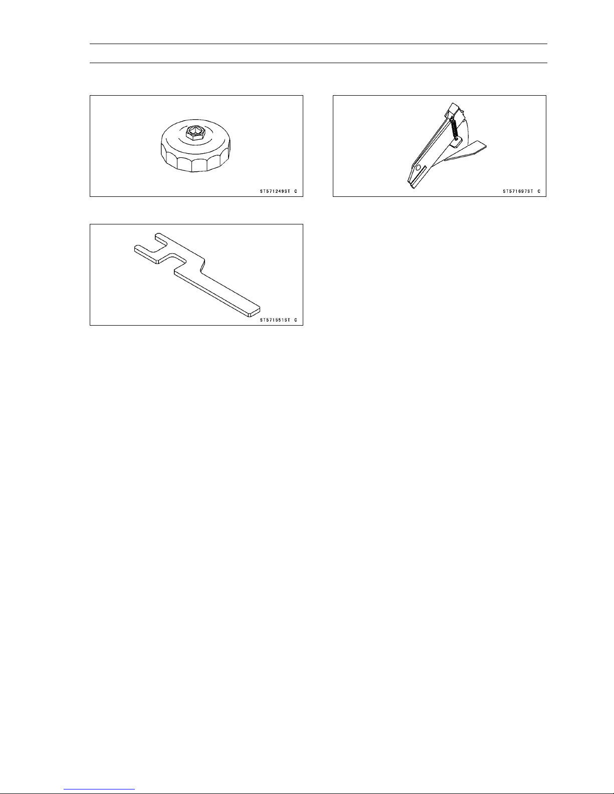
Special Tools and Sealant
PERIODIC MAINTENANCE 2-11
Oil Filter Wrench:
57001-1249
Shaft Wrench:
57001-1551
Belt Measuring Gauge:
57001-1697
Page 36
2-12 PERIODIC MAINTENANCE
Periodic Maintenance Procedures
Fuel System
Throttle Control System Inspection
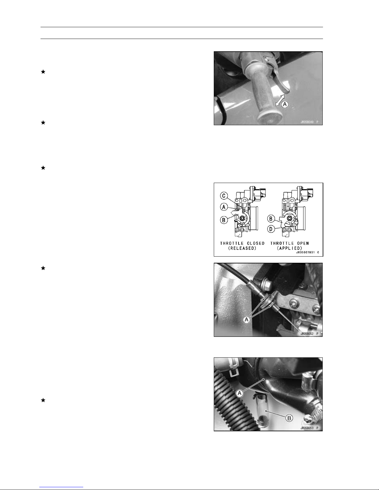
Inspect the throttle lever free play [A].
•
If the free play is incorrect, adjust the throttle cable.
Throttle Lever Free Play
Standard: about 2 mm (0.08 in.)
Check that the throttle lever moves smoothly from full
•
open to close, and the throttle closes quickly and completely in all steering positions by the return spring.
If the throttle lever does not return properly, check the
throttle cable routing, cable adjustments, and cable damage. Then lubricate the throttle cable.
Run the engine at the idle speed, and turn the handlebar
•
all the way to the right and left to ensure that the idle speed
does not change.
If the idle speed increase, check the throttle cable adjustment and the cable routing.
Remove the seats (see Seat Removal in the Hull/Engine
•
Hood chapter).
Check throttle cable adjustment.
•
With the throttle lever released, the upper stop [A] on the
•
throttle pivot arm [B] should rest against the stopper [C]
on the throttle body, and there should be slight slack in
the throttle cable.
When the throttle lever is fully applied (pulled), the lower
•
stop [D] on the pivot arm should be all the way up against
the stopper on the throttle body.
If necessary, adjust the throttle cable.
Loosen and turn the locknuts [A] at the bracket until the
•
upper stop on the pivot arm hits against the stopper on
the throttle body with slight cable slack.
Tighten the locknuts securely.
•
Torque - Throttle Cable Locknuts: 20 N·m (2.0 kgf·m, 14
ft·lb)
NOTE
Make sure that the throttle pivot arm stops against the
○
stopper on the throttle body with the throttle lever released.
Air Box Drain Cap Inspection and Cleaning
Remove the seats (see Seat Removal in the Hull/Engine
•
Hood chapter).
Inspect the air box [A] for water inside with its drain cap
•
[B].
If there is water in the cap, remove the cap and discharge
the water.
NOTE
Be sure to have a rag or cloth underneath for possible
○
oily water.
Page 37
Periodic Maintenance Procedures
Supercharger Drive Belt for Wear/Damage and
Belt Tension Inspection
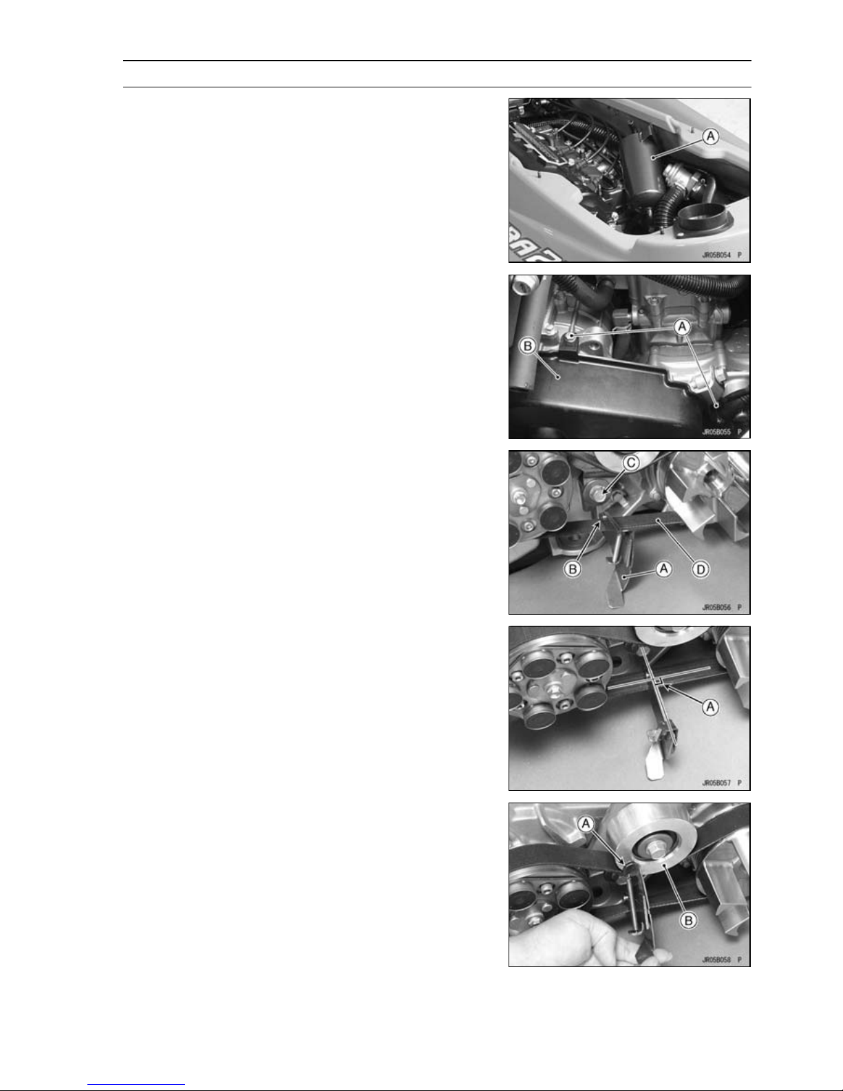
Inspect the supercharger drive belt tension as follows.
•
Disconnect the following from the oil separator tank.
•
Breather Hose (to Air Box)
Breather Hose (to Cylinder Head Cover)
Place the oil separator tank [A] as shown.
•
Remove:
•
Belt Cover Bolts [A]
Belt Cover [B]
PERIODIC MAINTENANCE 2-13
Install the special tool [A] onto the belt [D] so that the tool’s
•
tip [B] is aligned with the tensioner plate bolt head [C].
Special Tool - Belt Measuring Gauge [D]: 57001-1697
Ensure that the gage’s body is 90 degrees [A] to the belt.
•
Rotate the special tool (keeping it at 90 degrees to the
•
belt ) until it touches [A] the face [B] of the idler.
Page 38
2-14 PERIODIC MAINTENANCE
Periodic Maintenance Procedures
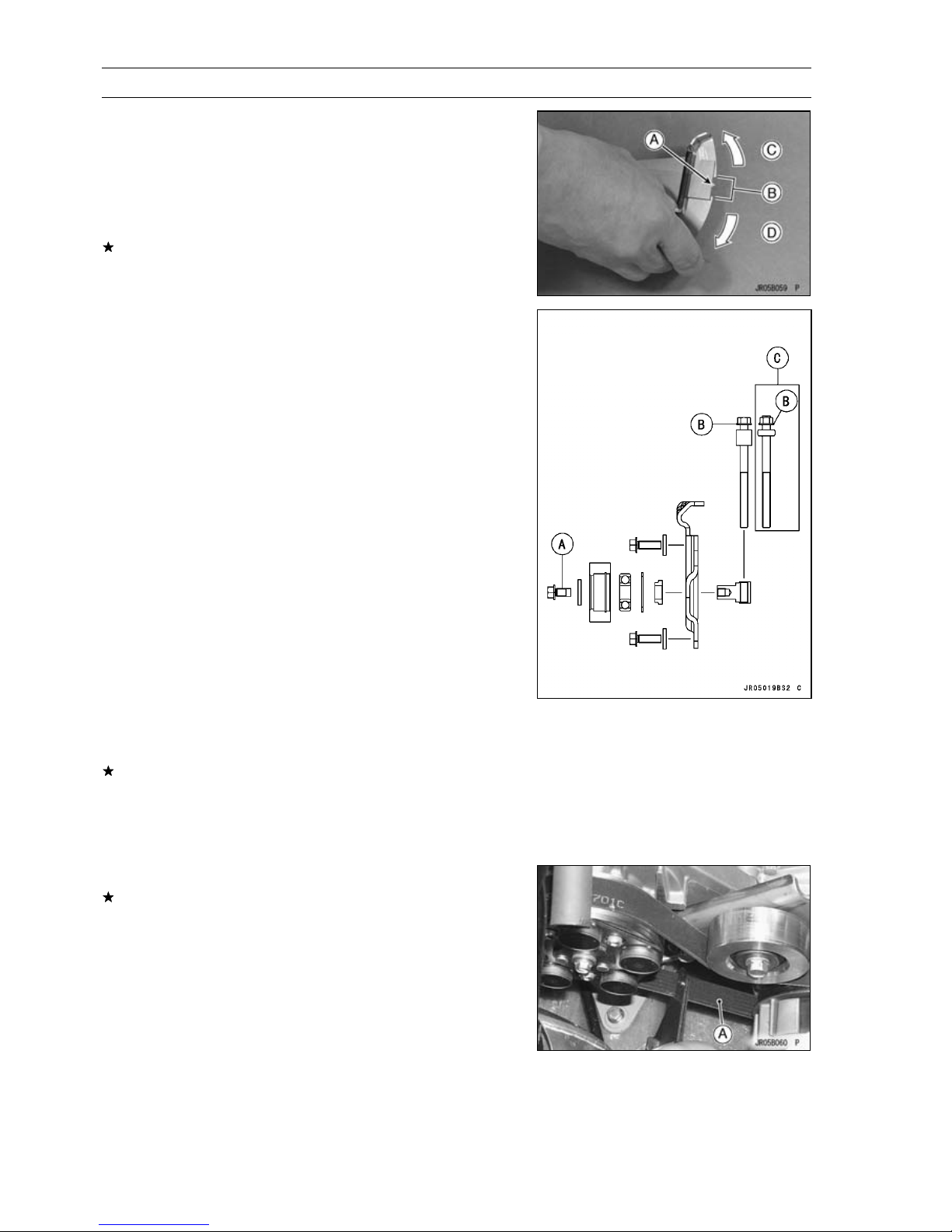
Check that the gauge indicator [A] is within the area [B] of
•
recess.
Belt Tension Range
Standard:
[C] Tension is weak.
[D] Tension is strong.
If the gauge indicator is without the area of recess, adjust
the belt tension.
Loosen the idler bolt [A].
•
To weaken the belt tension, turn the adjuster [B] counter-
•
clockwise.
To strengthen the belt tension, tighten the adjuster clock-
•
wise.
Torque - Belt Tension Adjuster: 3.0 N·m (0.31 kgf·m, 27
in·lb)
Tighten the idler bolt.
•
Torque - Idler Bolt: 30 N·m (3.1 kgf·m, 22 ft·lb)
JT1500B8F Model [C]
500 ∼ 960 Nm
Check the belt tension with the special tool.
•
Special Tool - Belt Measuring Gauge: 57001-1697
If the gauge indicator is without the area of recess, readjust the belt tension from the first procedure.
Lastly, disconnect the primary ignition coil lead connec-
•
tors and crank the engine for 5 seconds.
Recheck the belt tension.
•
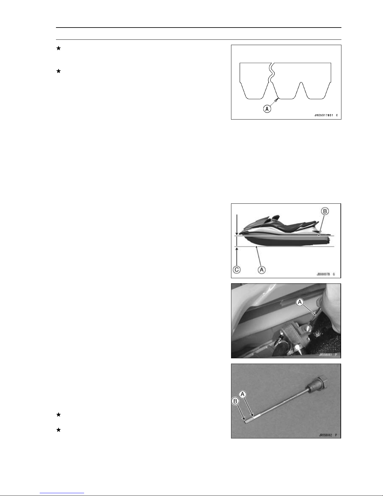
Visually inspect the belt [A] for wear and damage.
•
If the nylon fabric facing of any portion is worn off, and the
polyurethane compound is exposed, or belt is damaged,
replace the belt with a new one.
Page 39
Periodic Maintenance Procedures
If the belt teeth [A] are wear, replace the belt with a new
one (see Engine Removal in the Engine Removal/Installation chapter).
Whenever the belt is replaced, inspect the engine and
supercharger pulleys (see Engine Removal in the Engine
Removal/Installation chapter).
Supercharger Gear Oil Level Inspection
Remove the seat (see Seat Removal in the Hull/Engine
•
Hood chapter).
Remove the handrail plate (see Handrail Plate Removal
•
in the Hull/Engine Hood chapter).
Unscrew the exhaust tube clamp.
•
Remove the exhaust pipe and muffler body as a set (see
•
Exhaust Pipe and Muffler Body Removal in the Exhaust
System).
PERIODIC MAINTENANCE 2-15
Whenever checking the supercharger gear oil level, keep
•
the watercraft level side to side and fore to aft as much as
possible.
Level Ground [A]
Side Bumper [B]
Parallel [C]
Unscrew the oil level gauge [A].
•
Remove the oil level gauge, wipe it dry and insert it back
•
to the supercharger.
Fully, screw in the oil level gauge into the supercharger.
•
Remove the oil level gauge agail to check the oil level.
•
The oil level must be between the High [A] and Low [B]
•
level on the level gauge.
If the oil level is too high, remove the excess oil using a
syring or some other suitable device.
If the oil level is too low, add the oil to the low level line
thought the oil opening.
Supercharger Gear Oil:
Syntheso HT68 (NOK Kruber Brand)
Page 40
2-16 PERIODIC MAINTENANCE
Periodic Maintenance Procedures
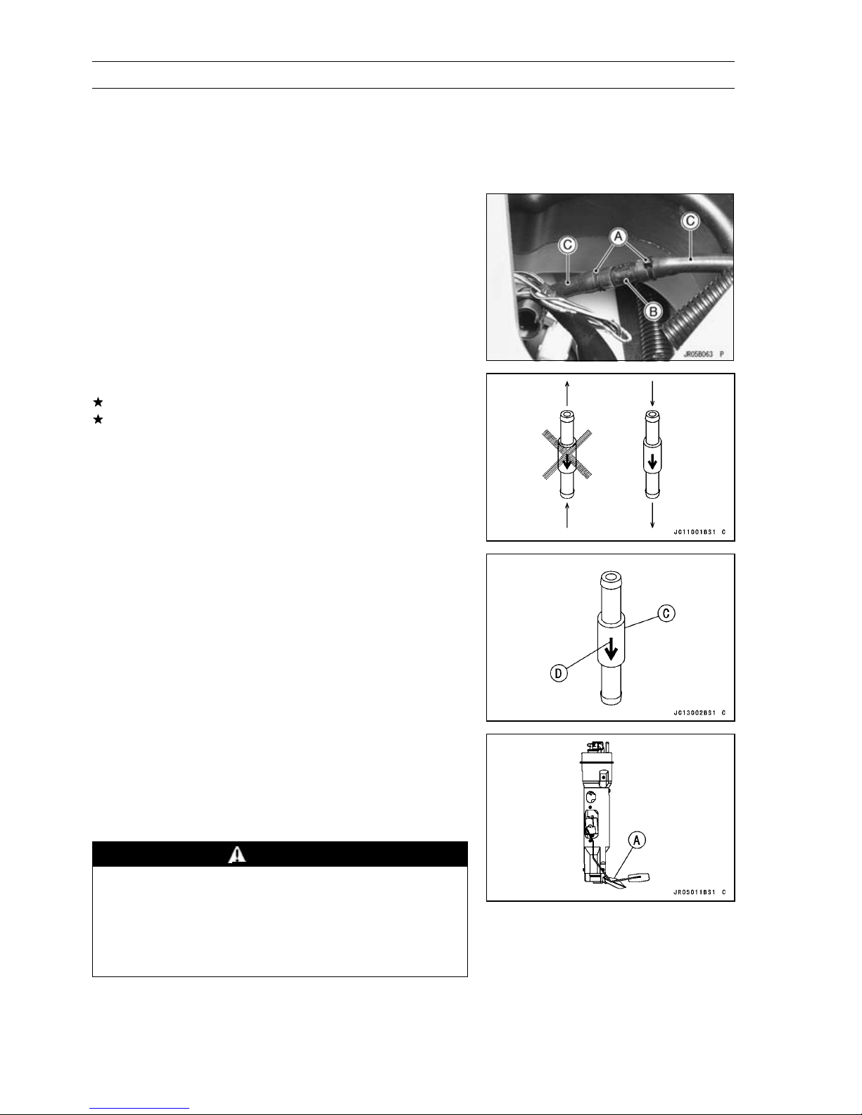
Fuel Vent Check Valve Inspection
The fuel vent check valve is mounted in the fuel tank vent
hose to prevent fuel from spilling during riding. Air can flow
into the tank to allow fuel to be drawn out by the fuel pump,
but fuel cannot flow out the check valve.
Remove the seats (see Seat Removal in the Hull/Engine
•
Hood chapter).
Cut off the bands [A].
•
Pull out each end of the fuel vent check valve [B] from the
•
vent hoses [C].
Blow through the fuel vent check valve from each end.
•
If the check valve will allow air to flow as shown, it is OK.
If air will flow through the check valve in both direction or
in neither direction, the check valve must be replaced.
The fuel vent check valve [C] must be mounted so that
•
the arrow [D] on its case is pointing toward the fuel tank.
Fuel Pump S creen Cleaning
Remove the fuel pump (see Fuel Pump Removal in the
•
Fuel System chapter).
Wash the fuel pump screen [A] in non-flammable of high
•
-flash point solvent. Use a brush to remove any contaminants trapped in the screens.
WARNING
Clean the fuel pump screen in a well-ventilated
area, and take ample care that there are no sparks
or flame anywhere near the working area; this
includes any appliance with a pilot light. Do not
use gasoline or a low flash-point solvent. A fire or
explosion could result.
Page 41
Periodic Maintenance Procedures
Throttle Shaft Spring Inspection
Remove the seat (see Seat Removal in the Hull/Engine
•
Hood chapter).
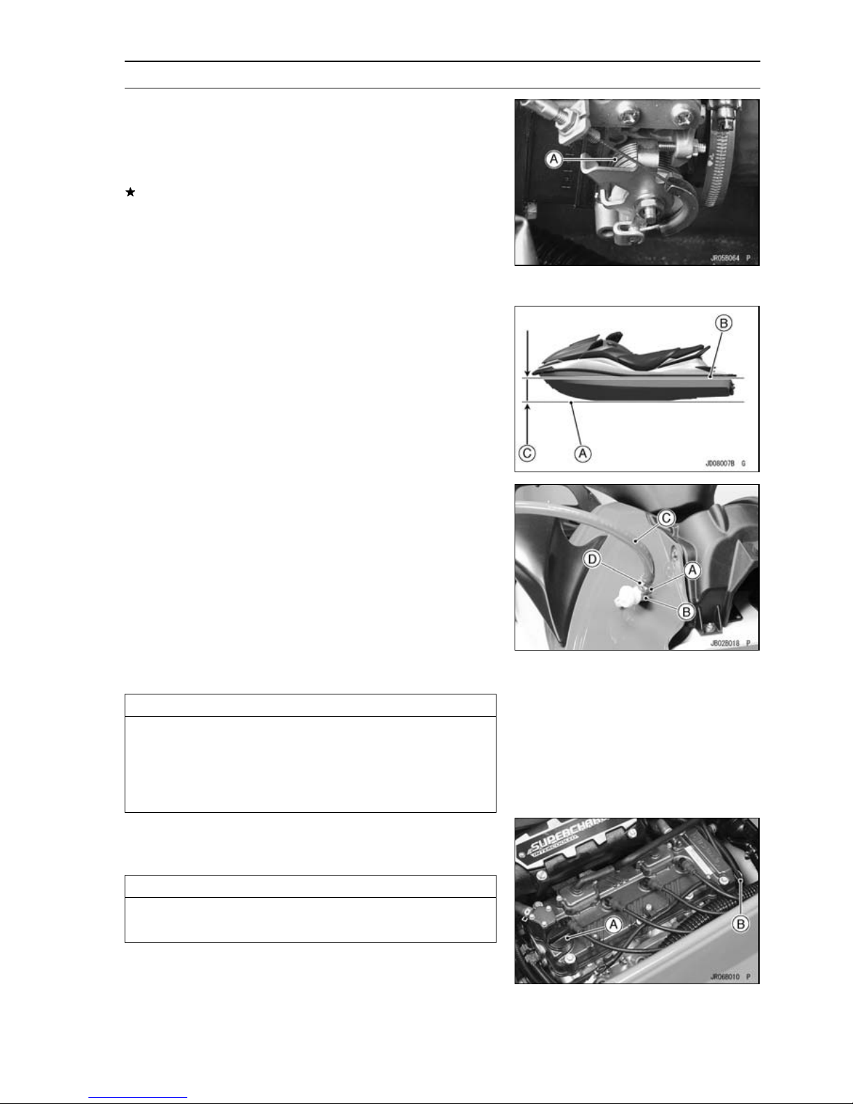
Check the throttle shaft spring [A] by pulling the throttle
•
lever.
If the springs are damaged or weak, replace the throttle
body.
Engine Lubrication System
Engine Oil Change
Level the watercraft port to starboard as well as fore to
•
aft.
Level Ground [A]
Side Bumper [B]
Parallel [C]
PERIODIC MAINTENANCE 2-17
In a well-ventilated area, start the engine while cooling the
•
cooling system.
Open the front storage compartment cover (see Front
○
Storage Compartment Cover Removal in the Hull/Engine
Hood chapter).
Remove the flushing cap (see Cooling System Flushing
○
in the Periodic Maintenance chapter).
Screw a garden hose adapter [A] onto the flushing fitting
○
[B].
Attach a garden hose [C] to a garden hose adapter and
○
secure the hose clamp [D].
Warm up the engine and stop it.
•
CAUTION
The engine must be running before the water is
turned on and the water must be turned off before
the engine is stopped.
Do not run the engine without cooling water flow for
more than 15 seconds.
Remove the seat (see Seat Removal in the Hull/Engine
•
Hood chapter).
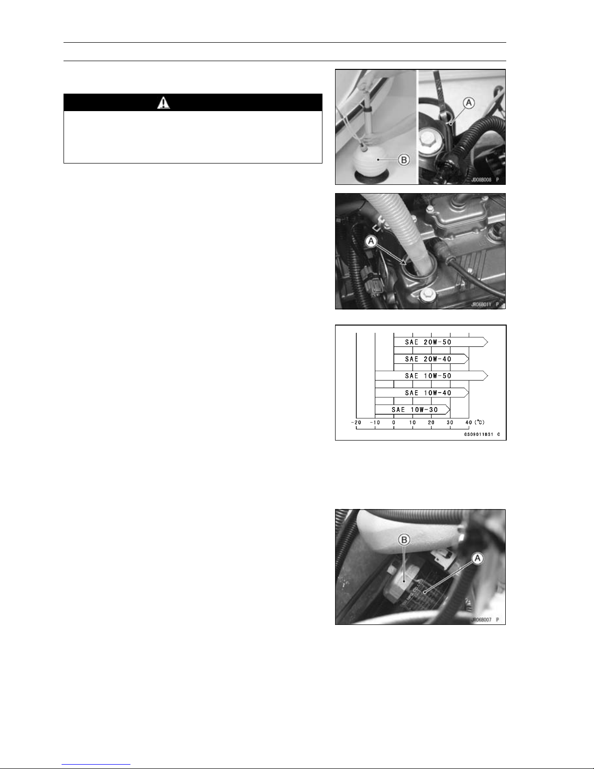
Remove the oil filler cap [A] and the dipstick [B].
•
CAUTION
Be careful not to allow any dirt or foreign materials
to enter the engine.
Page 42
2-18 PERIODIC MAINTENANCE
Periodic Maintenance Procedures
Drain the oil thoroughly from the dipstick tube [A] using a
•
commercially-available vacuum pump [B].
WARNING
Do not discard the engine oil as the engine oil is
toxic substance and will pollute the environment.
Contact your local au thority for approved disposal
methods.
Pour in the specified type and amount of oil through the
•
oil filler opening [A].
Engine Oil
Grade: API SE, SF or SG
API SH, SJ or S L with JASO MA
Viscosity:
Amount:
SAE 10W-40
4.0 L (4.2 US qt, with or without the filter)
5.0 L (5.3 US qt, when engine is completely
dry)
Depending on the atmospheric temperature of your riding
○
area, the engine oil viscosity should be changed according to the chart shown.
Install the filler cap.
•
Torque - Oil Filler Cap: 1.0 N·m (0.10 kgf·m, 8.7 in·lb)
Check the oil level (see Oil Level Inspection in the Engine
•
Lubrication System chapter).
Oil Filter Replacement
Remove:
•
Seat (see Seat Removal in the Hull/Engine Hood chap-
ter)
Drain the engine oil (see Engine Oil Change).
•
Disconnect the following to make service easy.
•
Air Bypass Hoses (Air Box Side)
Fuel Hose (Delivery Pipe Side)
Inlet Air Temperature Sensor Connector
Place a rag or cloth under the oil filter to receive the re-
•
maining oil.
Remove the oil filter [A] with the oil filter wrench [B].
•
Special Tool - Oil Filter Wrench: 57001-1249
Page 43
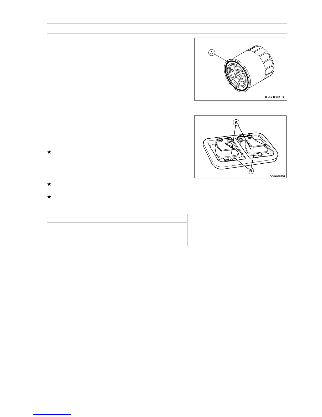
Periodic Maintenance Procedures
Replace the filter with a new one.
•
Apply engine oil to the gasket [A] before installation.
•
Tighten the filter with the oil filter wrench.
•
Torque - Oil Filter: 18 N·m (1.8 kgf·m, 13 ft·lb)
Pour in the specified type and amount of oil (see Engine
•
Oil Change).
Engine Top End
Air Suction Valve Inspection (JT1500B7F Model)
Remove the air suction valve (see Air Suction Valve Re-
•
moval in the Engine Top End chapter).
Visually inspect the reeds [A] for cracks, folds, warps,
•
heat damage, or other damage.
If there is any doubt as to the condition of the reed, replace
the air suction valve as an assembly.
Check the reed contact areas [B] of the valve holder for
•
grooves, scratches, any signs of separation from the
holder, or heat damage.
If there is any doubt as to the condition of the reed contact
areas, replace the air suction valve as an assembly.
If any carbon or other foreign particles have accumulated
between the reed and the reed contact area, wash the
valve assembly with a high-flash point solvent.
PERIODIC MAINTENANCE 2-19
CAUTION
Do not scrape off the deposits with a scraper as this
could damage the rubber, requiring replacement of
the suction valve assembly.
Valve Cleara nce Inspection
NOTE
Valve clearance must be checked and adjusted when
○
the engine is cold (at room temperature).
Remove:
•
Seat (see Seat Removal in the Hull/Engine Hood chapter)
Air Box (see Air Box Removal in the Fuel (DFI) System
chapter)
Cylinder Head Cover (see Cylinder Head Cover Removal in the Engine Top End chapter)
Position the crankshaft at #1, #4 piston TDC as follows.
•
Page 44
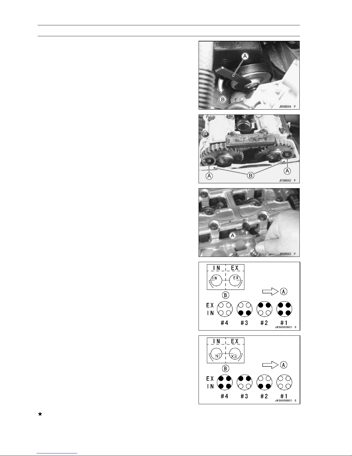
2-20 PERIODIC MAINTENANCE
Periodic Maintenance Procedures
Using the shaft wrench [A], turn the crankshaft counter-
○
clockwise [B] and set the crankshaft at #1, 4 piston TDC.
Special Tool - Shaft Wrench: 57001-1551
The timing marks [A] must be aligned with the cylinder
○
head upper surface [B] as shown.
Measure the valve clearance between the cam and the
•
valve lifter with a thickness gauge [A].
Valve Clearance
Standard:
IN 0.15 ∼ 0.24 mm (0.0059 ∼ 0.0094 in.)
EX 0.32 ∼ 0.41 mm (0.0126 ∼ 0.0161 in.)
When positioning #1 piston TDC at the end of the
○
compression stroke:
Inlet Valve Clearance of #1 and #3 Cylinders
Exhaust Valve Clearance of #1 and #2 Cylinders
Measuring Valve [
Bow [A]
Camshaft Sprocket Position [B]
When positioning #4 piston TDC at the end of the
○
compression stroke:
Inlet Valve Clearance of #2 and #4 Cylinders
Exhaust Valve Clearance of #3 and #4 Cylinders
Measuring Valve [
Bow [A]
Camshaft Sprocket Position [B]
]
•
]
•
If the v alve clearance is not within the specified range,
first record the clearance, and then adjust it.
Page 45
Periodic Maintenance Procedures
To change the valve clearance, remove the camshaft
•
chain tensioner, camshafts and valve lifters. Replace the
shim with one of a different thickness.
NOTE
Mark and record the valve lifter and shim locations so
○
they can be reinstalled in their original positions.
If there is no clearance, select a shim which is several
○
sizes smaller and then measure the clearance.
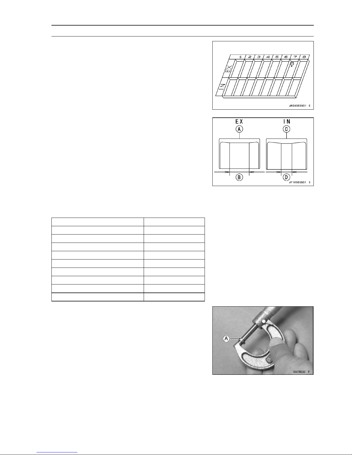
NOTE
For the EX valve lifters, JT1500B has larger size boss.
○
PERIODIC MAINTENANCE 2-21
EX Valve Lifters [A]
IN Valve Lifters [C]
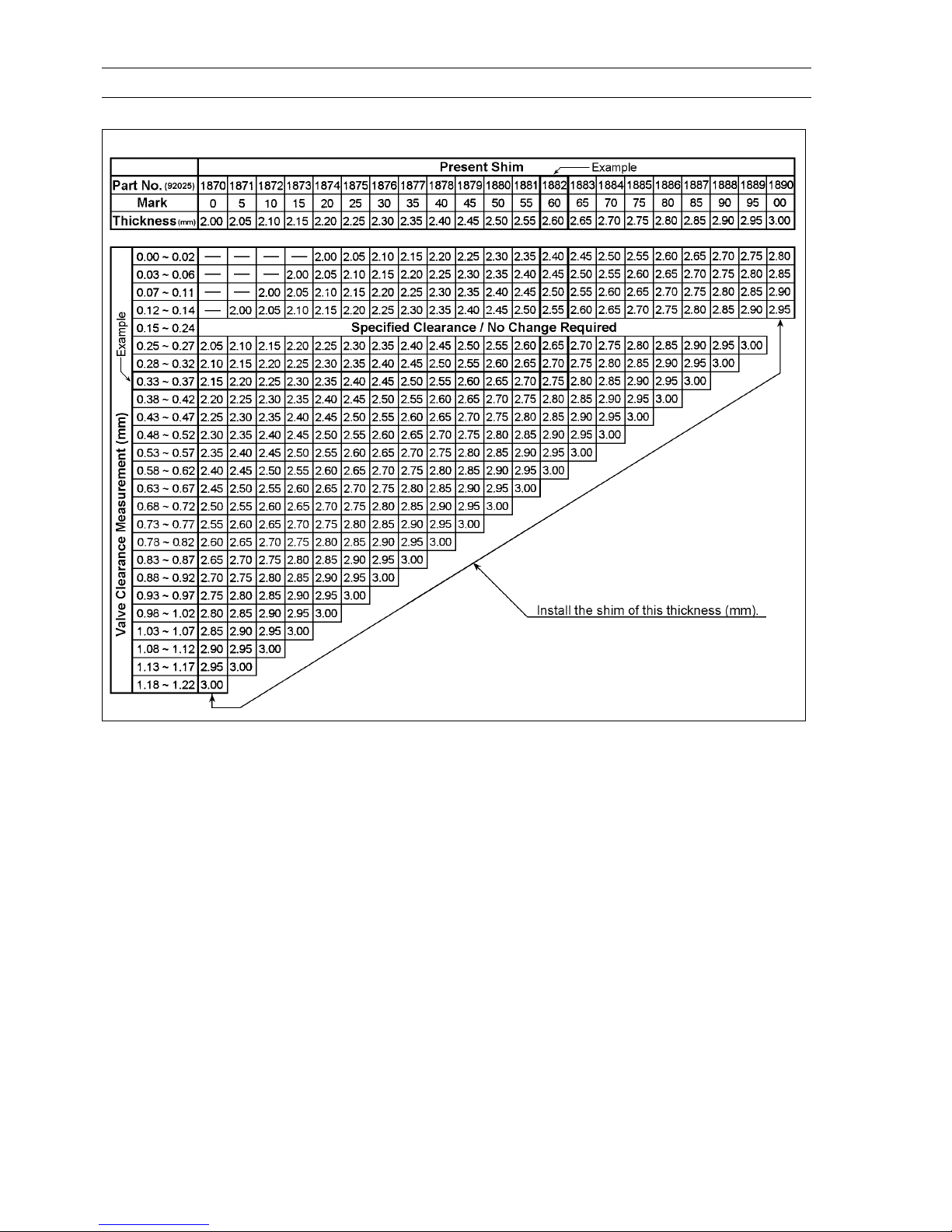
To select a new shim which brings the valve clearance
•
within the specified range, refer to the Valve Clearance
Adjustment Charts.
Bisides the standard shims in the valve clearance adjust-
○
ment charts, the following additional shims maybe used.
Adjustment Shims
Part Number Thickness
92025-1982 2.425 mm
92025-1983 2.475 mm
92025-1984 2.525 mm
92025-1985 2.575 mm
92180-1058 2.375 mm
92180-1059 2.625 mm
92180-1194 2.675 mm
92180-1195 2.725 mm
92180-1196 2.775 mm
: Boss diameter is larger [B]
: Boss diameter is smaller [D]
Clean the shim to remove any dust or oil.
•
Measure the thickness of the removed shim [A].
•
Page 46
2-22 PERIODIC MAINTENANCE
Periodic Maintenance Procedures
INLET VALVE CLEARANCE ADJUSTMENT CHART
1. Measure the clearance (when engine is cold).
2. Check present shim size.
3. Match clearance in vertical column w ith present shim
size in horizontal column.
4. Install the shim specified where the lines intersect.
This shim will give the proper clearance.
Example
Present shim is 2.60 mm .
Measured clearance is 0.35 mm.
Replace 2.60 mm shim with 2.75 mm shim.
5. Remeasure the valve clearance and readjust if necessary.
Page 47
PERIODIC MAINTENANCE 2-23
Periodic Maintenance Procedures
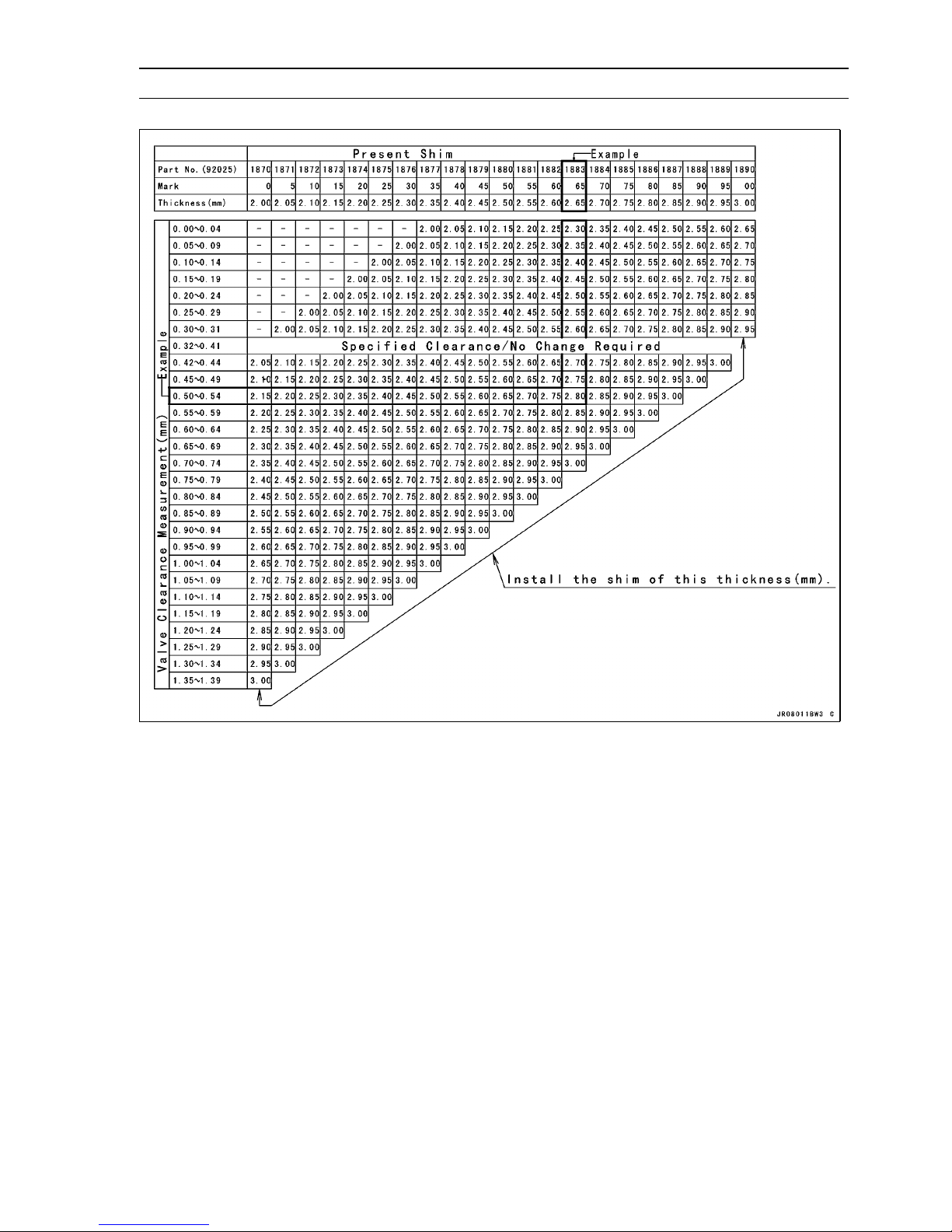
EXHAUST VALVE CLEARANCE ADJUSTMENT CHART
1. Measure the clearance (when engine is cold).
2. Check present shim size.
3. Match clearance in vertical column with present shim
size in horizontal column.
4. Install the shim specified where the lines intersect.
This shim will give the proper clearance.
Example
Present shim is 2.65 m m.
Measured clearance is 0.42 mm.
Replace 2.65 mm shim with 2.80 mm shim.
5. Remeasure the valve clearance and readjust if necessary.
Page 48
2-24 PERIODIC MAINTENANCE
Periodic Maintenance Procedures
Apply molybdenum disulfide oil to the valve lifters and ap-
•
ply engine oil to the shims, and install them.
Install the camshafts. Be sure to install the camshafts
•
properly (see Camshaft Installation in the Engine Top End
chapter).
Remeasure any valve clearance that was adjusted.
•
Readjust if necessary.
•
CAUTION
Do not put shim stock under the shim. This may
cause the shim to pop out at high rpm, causing extensive engine damage.
Do not grind the shim. This may cause it to fracture,
causing extensive engine damage.
Engine Mounting Bolts Inspection and Tightness
Check the tightness of the engine mounting bolts [A].
•
If there are loose bolts, remove the bolts.
Apply a non-permanent locking agent to the engine
•
mounting bolts and tighten them.
Torque - Engine Mounting Bolts: 36 N·m (3.7 kgf·m, 27 ft·lb)
Engine Bottom End
Coupling Damper Inspection
Remove:
•
Seat (see Seat Removal in the Hull/Engine Hood chapter)
Engine (see Engine Removal in the Engine Removal/Installation chapter)
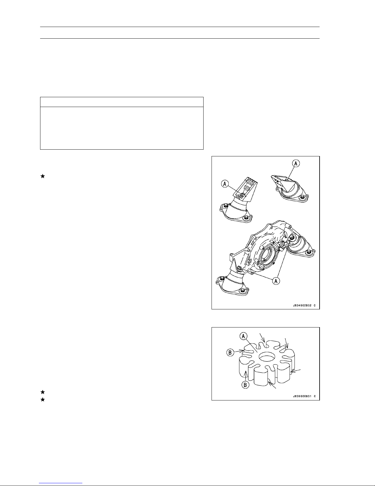
Remove the coupling damper [A] and inspect it for wear
•
[B] and deterioration.
If it is grooved or misshapen, replace it with a new damper.
If there is any doubt as to coupler condition, replace it.
Page 49
Periodic Maintenance Procedures
NOTE
The JT1500B has the damper with white mark [A].
○
Cooling and Bilge Systems
Cooling System Flushing
To prevent sand or salt deposits from accumulating in the
cooling system, it must be flushed occasionally. Flush the
system according to the Periodic Maintenance Chart, after
each use in salt water, or whenever there is reduced water
flow from the bypass outlet on the right side of the hull.
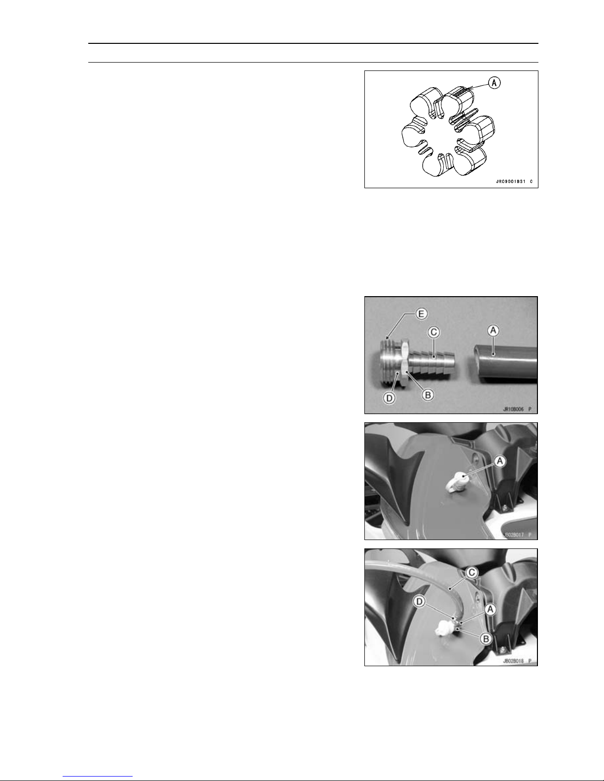
Obtain a standard garden hose [A] and a garden hose
•
adapter [B] as shown.
Garden Hose Fitting of Adapter [C]
Flushing Fitting of Adapter [D]
Thread: Rp 3/4 [E]
PERIODIC MAINTENANCE 2-25
NOTE
Optional part (P/No. 92005-3746) is available as a gar-
○
den hose adapter.
Open the front storage compartment cover (see Front
•
Storage Compartment Cover Removal).
Remove the flushing cap [A] on the brim of the engine
•
compartment.
Screw a garden hose adapter [A] onto the flushing fitting
•
[B].
Attach a garden hose [C] to a garden hose adapter and
•
secure the hose clamp [D].
Page 50
2-26 PERIODIC MAINTENANCE
Periodic Maintenance Procedures
Start the engine and allow it to idle before turning on the
•
water.
CAUTION
The engine must be running before the water is
turned on or water may flow back through the
exhaust pipe into the engine, resulting in the possibility of severe internal damage.
Immediately turn on the water and adjust the flow so that
•
a little trickle of water comes out of the bypass outlet [A]
on the right side of the hull.
Leave the engine idle for several minutes with the water
•
running.
Turn off the water. Leave the engine idling.
•
Rev the engine a few times to clear the water out of the
•
exhaust system.
CAUTION
Do not run the engine without cooling water supply
for more than 15 seconds, especially in high revolutionary speed or severe engine and exhaust system
damage will occur.
Switch off the engine, remove the garden hose and the
•
adapter.
Install the flushing cap securely.
•
Bilge System Flushing
To prevent clogging, the bilge system should be flushed
out according to the Periodic Maintenance Chart, or whenever you suspect it is blocked.
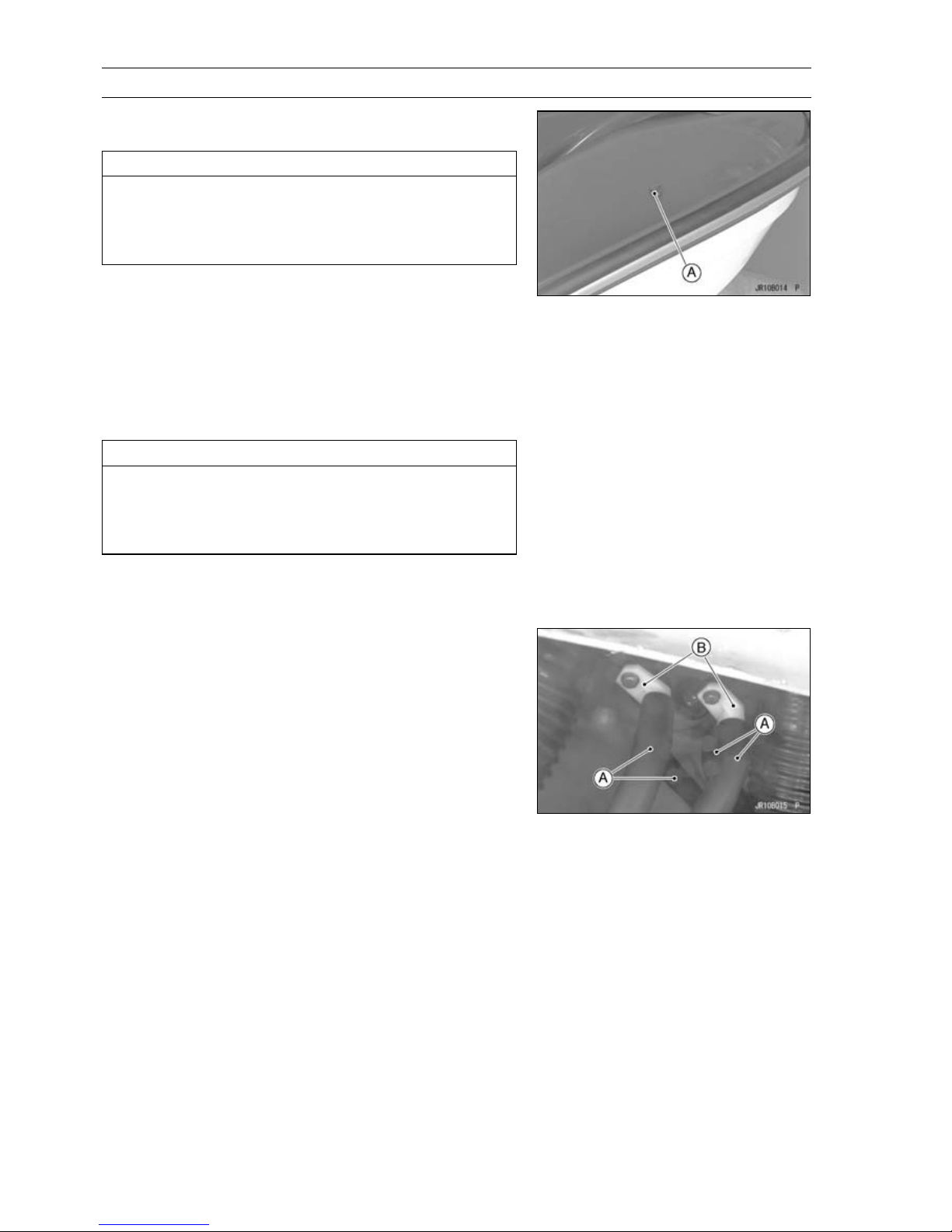
Disconnect both bilge hoses [A] at the plastic breather
•
fitting [B].
Connect the bilge filter hoses (from the hull bottom) to the
•
garden hoses, turn the water on, and flush it out for about
a minute. During this procedure, water will flow into the
engine compartment. Do not allow a large amount of wa-
ter to accumulate in the engine compartment. Remove
the drain screws in the stern to drain the engine compart-
ment.
Connect the other hoses (from the hull bulkhead) to the
•
garden hose, turn the water on, and flush it out for several
minutes.
Page 51
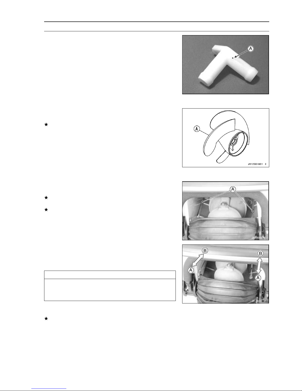
Periodic Maintenance Procedures
Before reconnecting the hoses to the plastic breather fit-
•
ting make sure the small hole [A], on top of the breather
fitting is clear.
Reconnect the bilge hoses.
•
Pump and Impeller
Impeller Inspection
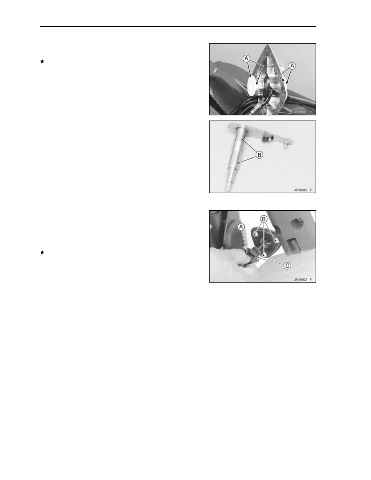
Examine the impeller. [A]
•
If there is pitting, deep scratches, nicks or other damage,
replace the impeller.
NOTE
Minor nicks and gouges in the impeller blades can be
○
removed with abrasive paper or careful filing. Smooth
leading edges are especially important to avoid cavitation.
PERIODIC MAINTENANCE 2-27
Steering
Steering Cable/Shift Cable Inspection
Examine the steering cable or shift cable.
•
If each cable or cable housing is kinked or frayed, replace
the cables.
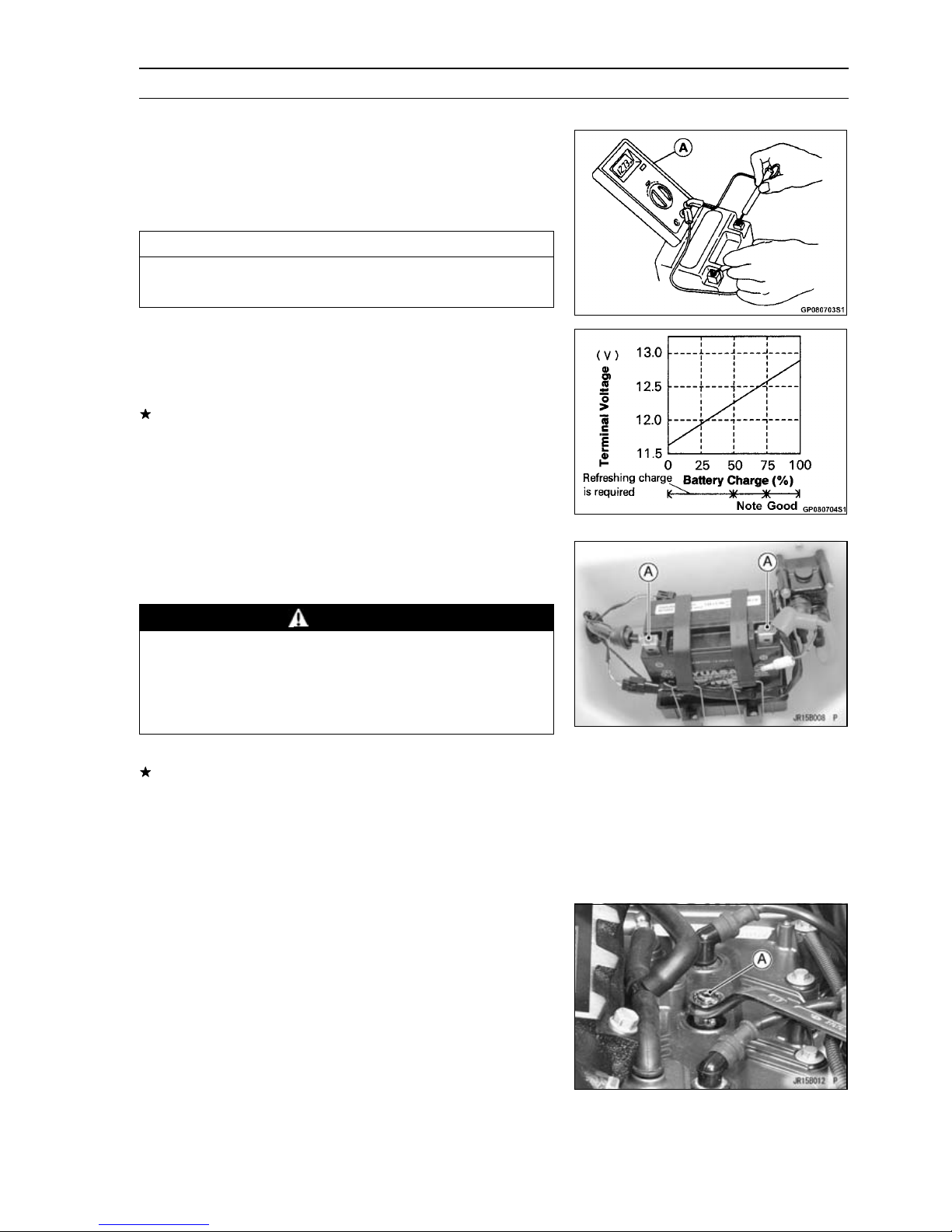
If the each seal [A] at either end of each cable is damaged
in any way, replace the cables.
Be certain that each cable moves freely in both directions.
•
Disconnect the cable joints at each end of each cable.
•
Take out the cable joint bolt or ball joint and disconnect
○
the cable joint.
CAUTION
Never lay the watercraft on the right side. Water in
the exhaust system may drain back into the engine
causing serious damage.
Slide the inner cable back [A] and forth [B] in each cable
○
housings.
If each cable does not move freely, replace it.
Page 52
2-28 PERIODIC MAINTENANCE
Periodic Maintenance Procedures
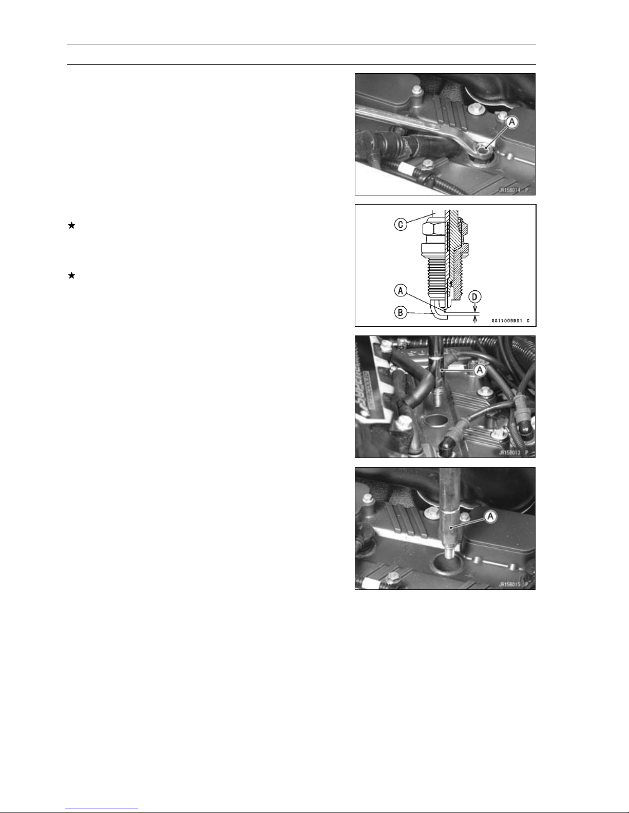
Handlebar Pivot Lubrication
Check the bushings for damage and wear.
•
If the bushings are damaged or worn, replace them.
Grease:
•
Bushings [A]
Steering Shaft [B]
Hull/Engine Hood
DrainPlugInspection
Check the drain plugs [A] for cracks or damage and make
•
sure the drain plug mounting screws [B] are tightened se-
curely.
Check the seals [C] for damage.
•
If necessary, replace the drain plugs or seals.
Page 53
Periodic Maintenance Procedures
Electrical System
Battery Charging Condition Inspection
Battery charging condition can be checked by measuring
battery terminal voltage.
Disconnect the battery terminal cables (see Battery Re-
•
moval in the Electrical System chapter).
CAUTION
Be sure to disconnect the negative terminal cable
first.
Measure the battery terminal voltage.
•
NOTE
Measure with a digital voltmeter [A] which can be read
○
one decimal place voltage.
If the reading is below the specified, refreshing charge is
required (see Refreshing Charge in the Electrical System
chapter).
Battery Terminal Voltage
Standard:
Connect the battery cables, positive first.
•
Battery Terminals Inspection
Check the battery terminal screws [A] for tightness and
•
make sure the terminal covers are in place.
12.8 V or more
PERIODIC MAINTENANCE 2-29
WARNING
Loose battery cables can create sparks which can
cause a fire or explosion resulting in injury or death.
Make sure the battery terminal screws are tightened
securely and the covers are installed over the terminals.
Check that the battery terminals are not corroded.
•
If necessary, remove the battery (see Battery Removal
in the Electrical System chapter) and clean the terminals
and cable ends using a solution of baking soda and water.
After attaching both cables, coat the terminals and cable
•
ends with grease to prevent corrosion.
Install the battery (see Battery Installation in the Electrical
•
System chapter).
Spark Plug Inspection
Remove:
•
Seat (see Seat Removal in the Hull/Engine Hood chapter)
Spark Plug Caps
Remove the spark plugs using the 16 mm plug wrench
•
[A].
Owner’s Tool - Spark Plug Wrench, 16 mm: 92110-3706
Page 54
2-30 PERIODIC MAINTENANCE
Periodic Maintenance Procedures
JT1500B8F Model
•
Visually inspect the spark plugs.
•
If the spark plug center electrode [A] and/or side elec-
trode [B] are corroded or damaged, or if the insulator [C]
is cracked, replace the plug.
Measure the gaps [D] with a wire-type thickness gauge.
•
If the gap is incorrect, replace the spark plug.
Spark Plug Gap: 0 .6 ∼ 0.7 mm (0.024 ∼ 0.028 in.)
Insertthesparkplugverticallyintotheplugholewiththe
•
spark plug installed in the plug wrench [A].
Owner’s Tool - Spark Plug Wrench, 16 mm: 92110-3706
Tighten:
•
Torque - Spark Plugs: 13 N·m (1.3 kgf·m, 113 in·lb)
Be sure to install the plug caps so that the plug cap leads
•
are positioned at a right angle to the engine center line
(see Cable, Wire and Hose Routing section in the Appen-
dix chapter).
JT1500B8F Model
•
Lubrication
As in all marine craft, adequate lubrication and corrosion
protection is an absolute necessity to provide long, reliable
service. Refer to the Periodic Maintenance Chart for the
frequency of the following items:
Page 55
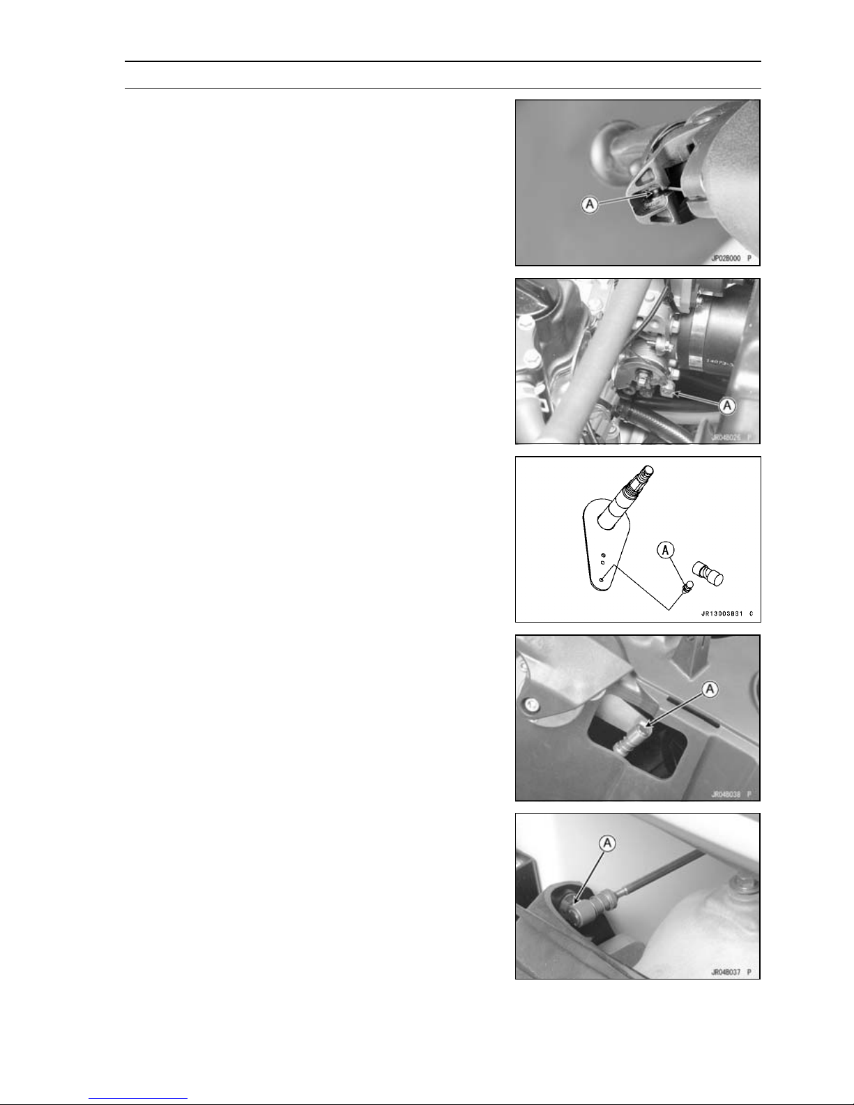
Periodic Maintenance Procedures
Lubricate the following with grease.
•
Pull the throttle lever and hold it.
○
Throttle Cable End [A] at Throttle Lever
Throttle Cable End [A] at Throttle Body
PERIODIC MAINTENANCE 2-31
Remove the steering cover (see Steering Cover Removal
○
in the Hull/Engine Hood chapter).
Steering Cable Ball Joint [A] at Steering Shaft
Remove the left side cover (see Side Cover Removal in
○
the Hull/Engine Hood chapter).
Shift Cable Ball Joint [A] at Reverse Lever
Shift Cable Ball Joint [A] at Reverse Bucket
Page 56
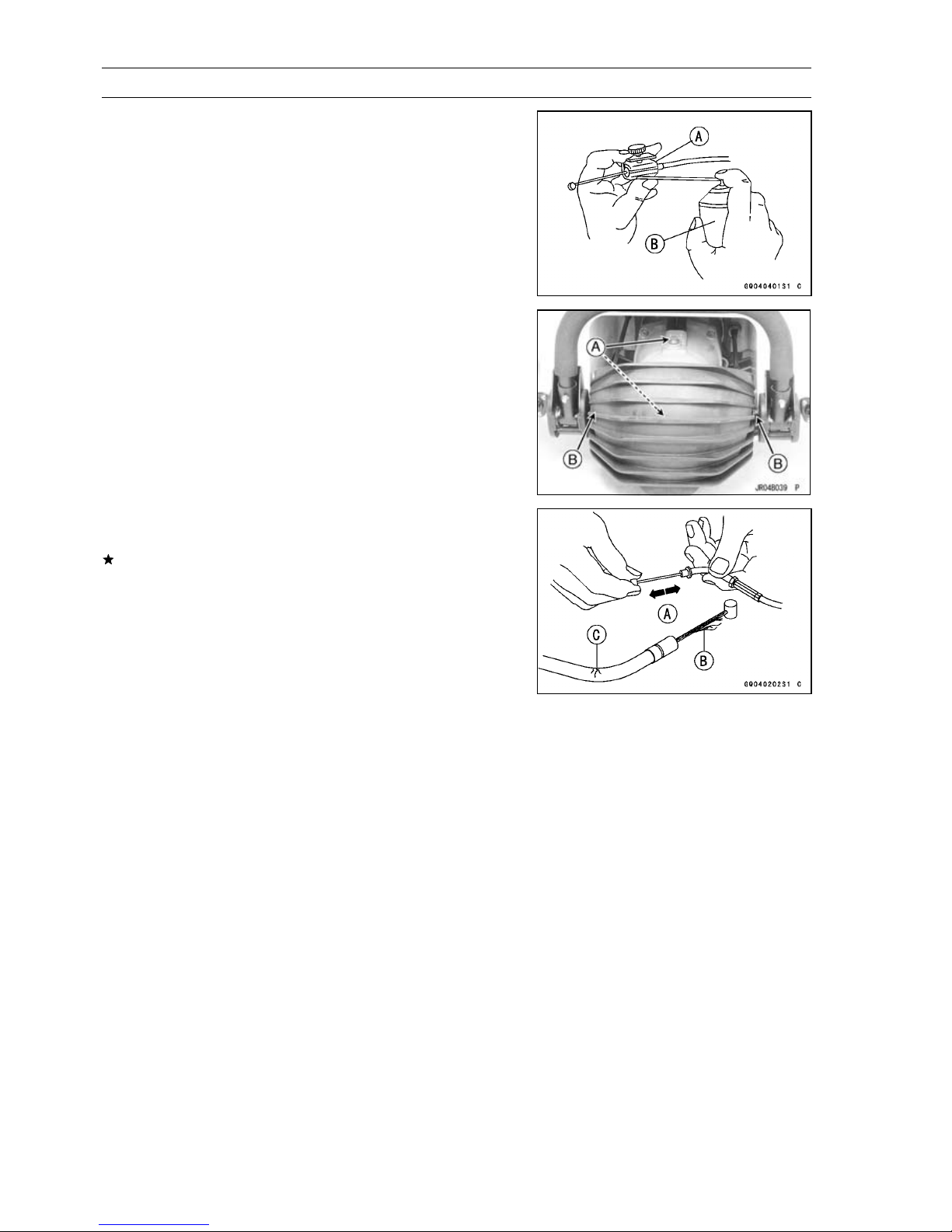
2-32 PERIODIC MAINTENANCE
Periodic Maintenance Procedures
Lubricate the following with a penetrating rust inhibitor [B].
•
Throttle Cable [A]
Steering Nozzle Pivots [A]
Reverse Bucket Pivots [B]
With the cable disconnected at both ends, the cable
•
should move freely [A] within the cable housing.
If cable movement is not free after lubricating, if the cable
is frayed [B], or if the cable housing is kinked [C], replace
the cable.
Page 57
PERIODIC MAINTENANCE 2-33
Periodic Maintenance Procedures
All Hoses, Hose Clamps, Nuts, Bolts and Fasteners Check
Nuts, Bolts, and Fasteners Tightness Inspection
Check the tightness of the bolts and nuts listed here. Also,
•
check to see that each cotter pin is in place and in good
condition.
NOTE
For the engine fasteners, check the tightness of them
○
when the engine is cold (at room temperature).
If there are loose fasteners, retighten them to the specified torque following the specified tightening sequence.
Refer to the appropriate chapter for torque specifications.
If torque specifications are not in the appropriate chapter,
see the Standard Torque Table. For each fastener, first
loosen it by 1/2 turn, then tighten it.
If cotter pins are damaged, replace them with new ones.
Nut, Bolt and Fastener to be checked
Engine:
Oil Filter Cartridge
Engine Mounting Bolts (and bracket bolts)
Engine Damper Mounting Bolts
Cylinder Head Cover Bolts
Cylinder Head Bolts
Drive Shaft, Pump, and Impeller:
Drive Shaft Holder Mounting Bolts
Pump Mounting Bolts
Pump Cover Mounting Bolts
Pump Grate Mounting Bolts
Steering Nozzle Pivot Bolts
Reverse Bucket Pivot Bolts
Steering:
Handlebar Clamp Bolts
Steering Neck Mounting Bolts
Steering Holder Mounting Bolts
Steering Shaft Locknut
Steering Cable Nut
Steering Cable Joint Bolt
Shift (reverse) Cable Nut
Hull and Engine Hood:
Stabilizer Mounting Bolts
Rear Grip Plate Mounting Bolts
Electrical System:
Spark Plugs
Battery Terminal
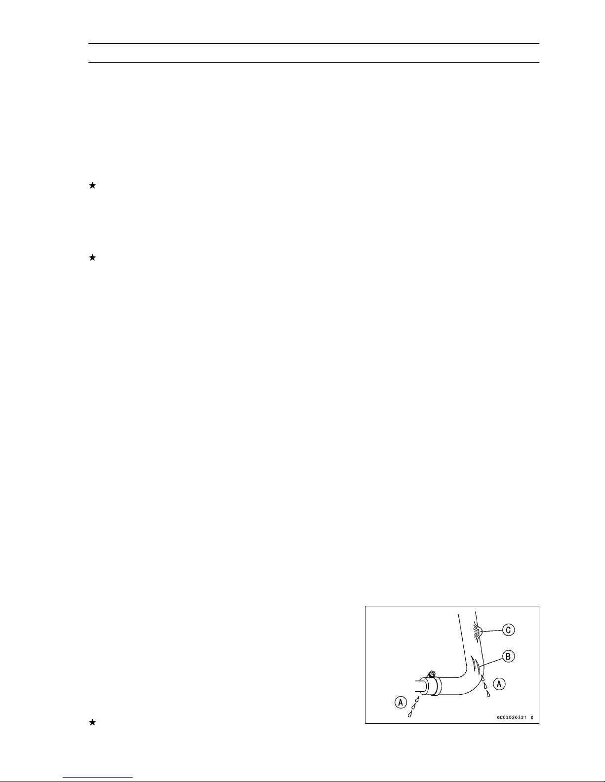
Hose and Hose Connect Inspection
Check the following hoses for leakage [A], hardening,
•
cracking [B], checking, cuts, abrasions, breaks and
bulges [C]. And make sure the hoses are not kinked or
pinched.
Fuel Vent Hose
Oil Hoses
Cooling Hoses
Bilge Hoses
If a hose is damaged in any way, replace it immediately
and check all the others for damage.
Page 58
2-34 PERIODIC MAINTENANCE
Periodic Maintenance Procedures
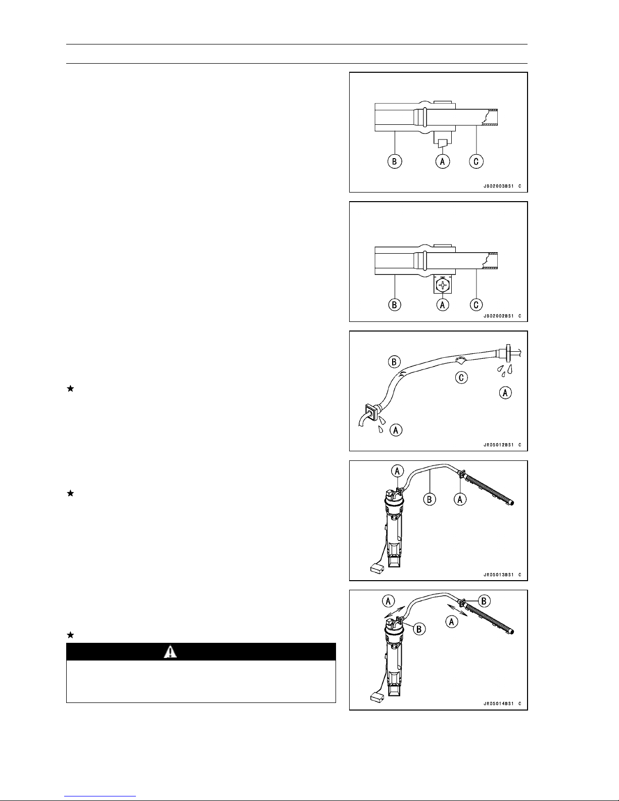
Make sure the above hoses are routed properly and se-
•
cured with the clamps away from any moving parts and
sharp edged portions.
Plastic Clamp [A]
Hose [B]
Hose Fitting [C]
NOTE
The majority of bilge hoses have no clamps at the hose
○
ends.
Metal Clamp [A]
Hose [B]
Hose Fitting [C]
NOTE
Check the fuel and exhaust tubes for signs of wear, de-
○
terioration, damage or leakage. Replace if necessary.
Make sure the above tubes are secured with the metal
○
gear clamps away from any parts.
If the watercraft is not properly handled, the high pres-
•
sure inside the fuel line can cause fuel to leak [A] or the
hose to burst. Remove the seat (see Seat Removal in the
Hull/Engine Hood chapter) and check the fuel hose.
Replace the fuel hose if any fraying, cracks [B] or bulges
[C] are noticed.
Check that the hoses are routed according to Cable, Wire,
•
and Hose Routing section in the Appendix chapter.
Replace the hose if it has been sharply bent or kinked.
Hose Joints [A]
Fuel Hose [B]
Check that the hose joints are securely connected.
•
Push and pull [A] the hose joint [B] back and forth more
○
than two times, and make sure it is locked.
If it does not locked, reinstall the hose joint.
WARNING
Make sure the hose joint is installed correctly on the
delivery pipe by sliding the joint, or the fuel could
leak.
Page 59
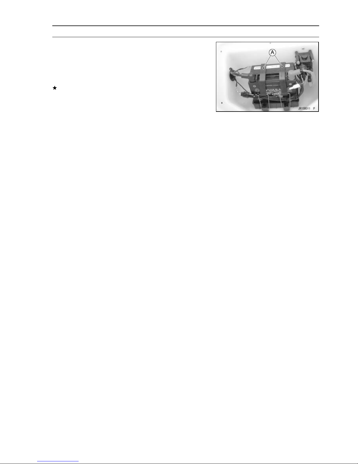
Periodic Maintenance Procedures
Rubber Strap Inspection
Check the following rubber straps for any deterioration or
•
damage. Pull on squeeze the straps and look for cracks.
Battery Straps [A]
Fuel Tank Straps
Water Box Muffler Straps
If a strap is damage in any way, replace it.
PERIODIC MAINTENANCE 2-35
Page 60

Page 61
FUEL SYSTEM (DFI) 3-1
Fuel System (DFI)
Table of Contents
Fuel System Diagram........................ 3-3
Exploded View................................... 3-4
Specifications .................................... 3-10
Special Tools and Sealant ................. 3-12
DFI Parts Location............................. 3-14
DFI System........................................ 3-16
DFI Servicing Precautions................. 3-19
Self-Diagnosis ................................... 3-21
Self-diagnosis Outline..................... 3-21
Service Code (Character) Table ..... 3-22
Troubleshooting the DFI System ....... 3-24
Throttle Sensor (Service
Code/Character-11/tPS) ................. 3-26
Throttle Sensor Removal/Adjust-
ment .......................................... 3-26
Input Voltage Inspection............... 3-27
Output Voltage Inspection............ 3-29
Resistance Inspection.................. 3-30
Inlet Air Pressure Sensor (Service
Code/Character-12/bOSt) ............... 3-32
Inlet Air Pressure Sensor
Removal .................................... 3-32
Inlet Air Pressure Sensor
Installation ................................. 3-32
Input Voltage Inspection............... 3-32
Output Voltage Inspection............ 3-33
Inlet Air Temperature Sensor (Service
Code/Character-13/AIrt) ................. 3-35
Inlet Air Temperature
Removal/Installation .................. 3-35
Output Voltage Inspection............ 3-35
Sensor Resistance Inspection ..... 3-36
Water Temperature Sensor (Service
Code/Character-14/AqUt) ............... 3-38
Water Temperature Sensor
Removal/Installation .................. 3-38
Output Voltage Inspection............ 3-38
Sensor Resistance Inspection ..... 3-40
Charging Temperature Sensor
(Service Code/Character-19/PrET). 3-41
Charging Temperature Sensor
Removal/Installation .................. 3-41
Output Voltage Inspection............ 3-41
Sensor Resistance Inspection ..... 3-42
Crankshaft Sensor (Service
Code/Character-21/CrAg) ............... 3-43
Crankshaft Sensor
Removal/Installation .................. 3-43
Crankshaft Sensor Inspection...... 3-43
Camshaft Position Sensor (Service
Code/Character-23/CAA1).............. 3-44
Camshaft Position Sensor
Removal/Installation .................. 3-44
Camshaft Position Sensor
Inspection.................................. 3-44
Vehicle-down Sensor (Service
Code/Character-31/dOS)................ 3-45
Vehicle-down Sensor Removal.... 3-45
Vehicle-down Sensor Installation. 3-45
Vehicle-down Sensor Inspection.. 3-46
Immobilizer Amplifier (Service
Code/Character-35/IdA).................. 3-48
Amplifier Input Voltage Inspection 3-48
Key Collation Error (Service
Code/Character-36/IdEr) ................ 3-49
User Key Inspection..................... 3-49
Ignition Coils (Service
Code/Character-51, 52/COL1,
COL2) ............................................. 3-50
Ignition Coil Removal/Installation. 3-50
Input Voltage Inspection............... 3-50
Engine Overheating (Service
Code/Character-71/HEAt)............... 3-52
Low Engine Oil Pressure (Service
Code/Character-72/OILP)............... 3-53
Oil Temperature Sensor (Service
Code/Character-73/OILt) ................ 3-54
Oil Temperature Sensor
Removal/Installation .................. 3-54
Output Voltage Inspection............ 3-54
Sensor Resistance Inspection ..... 3-55
Main (ECU) Relay and System Relay
(Service Code/Character-75/rEL) ... 3-56
Relay Assembly Removal............ 3-56
Relay Assembly Inspection.......... 3-56
Engine Oil Overheating (Service
Code/Character-76/OILH)............... 3-57
Charging (Intake) Temperature
Overheating (Service
Code/Character-78/CHAr) .............. 3-58
Fuel Injectors ..................................... 3-59
Fuel Injector Removal.................. 3-59
Fuel Injector Installation............... 3-60
Audible Inspection........................ 3-60
Injector Signal Test....................... 3-61
Injector Resistance Inspection..... 3-61
Injector Unit Test .......................... 3-62
Injector Voltage Inspection........... 3-62
Injector Fuel Line Inspection ........ 3-64
3
Page 62

3-2 FUEL SYSTEM (DFI)
ECU................................................... 3-66
ECU Removal .............................. 3-66
ECU Installation ........................... 3-66
ECU Power Supply Inspection..... 3-66
DFI Power Source ............................. 3-69
Main Fuse Inspection................... 3-69
Relay Assembly Removal............ 3-69
Relay Assembly Inspection.......... 3-69
Throttle Lever, Cable and Case......... 3-70
Free Play Inspection .................... 3-70
Throttle Cable Adjustment ........... 3-70
Throttle Case Removal/Disas-
sembly....................................... 3-70
Throttle Case Assembly/Installa-
tion ............................................ 3-71
Throttle Cable Removal ............... 3-72
Throttle Cable Installation ............ 3-73
Throttle Case and Cable
Lubrication................................. 3-73
Throttle Cable Inspection............. 3-73
Air Box ............................................... 3-74
Air Box Removal .......................... 3-74
Air Box Installation ....................... 3-74
Supercharger..................................... 3-75
Supercharger Removal ................ 3-75
Supercharger Installation ............. 3-75
Supercharger Disassembly.......... 3-75
Supercharger Assembly............... 3-76
Throttle Body Assy ............................ 3-78
Idle Speed Inspection .................. 3-78
High Altitude Performance
Adjustment ................................ 3-78
Throttle Body Assy Removal........ 3-78
Throttle Body Assy Installation..... 3-78
Throttle Body Assy Disassembly . 3-79
Throttle Bore Cleaning................. 3-79
ISC (Idle Speed Controller)
Removal .................................... 3-79
ISC (Idle Speed Controller)
Inspection.................................. 3-80
ISC Resistance Inspection........... 3-80
Inlet Manifold ..................................... 3-82
Inlet Manifold Removal ................ 3-82
Inlet Manifold Installation ............. 3-83
Fuel Line............................................ 3-85
Fuel Hose Removal ..................... 3-85
Fuel Hose Installation .................. 3-85
Fuel Pressure Inspection ............. 3-86
Fuel Flow Rate Inspection ........... 3-87
Fuel Vent Check Valve ...................... 3-89
Fuel Vent Check Valve Mounting . 3-89
Fuel Vent Check Valve Inspection 3-89
Fuel Pump ......................................... 3-90
Fuel Pump Removal .................... 3-90
Fuel Pump Installation ................. 3-91
Power Source Voltage Inspection 3-92
Operating Voltage Inspection....... 3-93
Fuel Pump Relay Removal .......... 3-94
Fuel Pump Relay Inspection ........ 3-94
Fuel Tank ........................................... 3-95
Fuel Tank Removal ...................... 3-95
Fuel Tank Installation ................... 3-96
Fuel Tank Cleaning ...................... 3-96
Fuel Filler and Tube Removal ...... 3-97
Fuel Filler and Tube Installation ... 3-98
Page 63
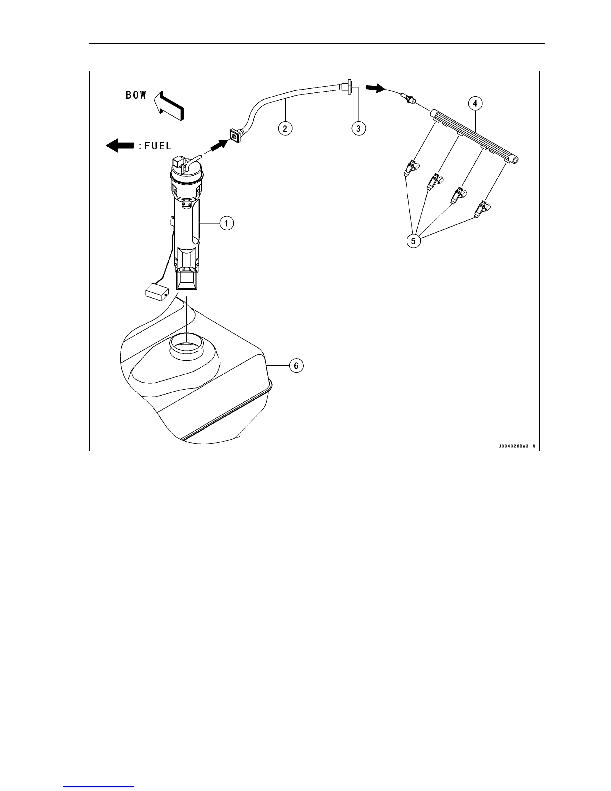
Fuel System Diagram
FUEL SYSTEM (DFI) 3-3
1. Fuel Pump
2. Fuel Hose
3. Supply Line
4. Delivery Pipe
5. Fuel Injectors
6. Fuel Tank
Page 64
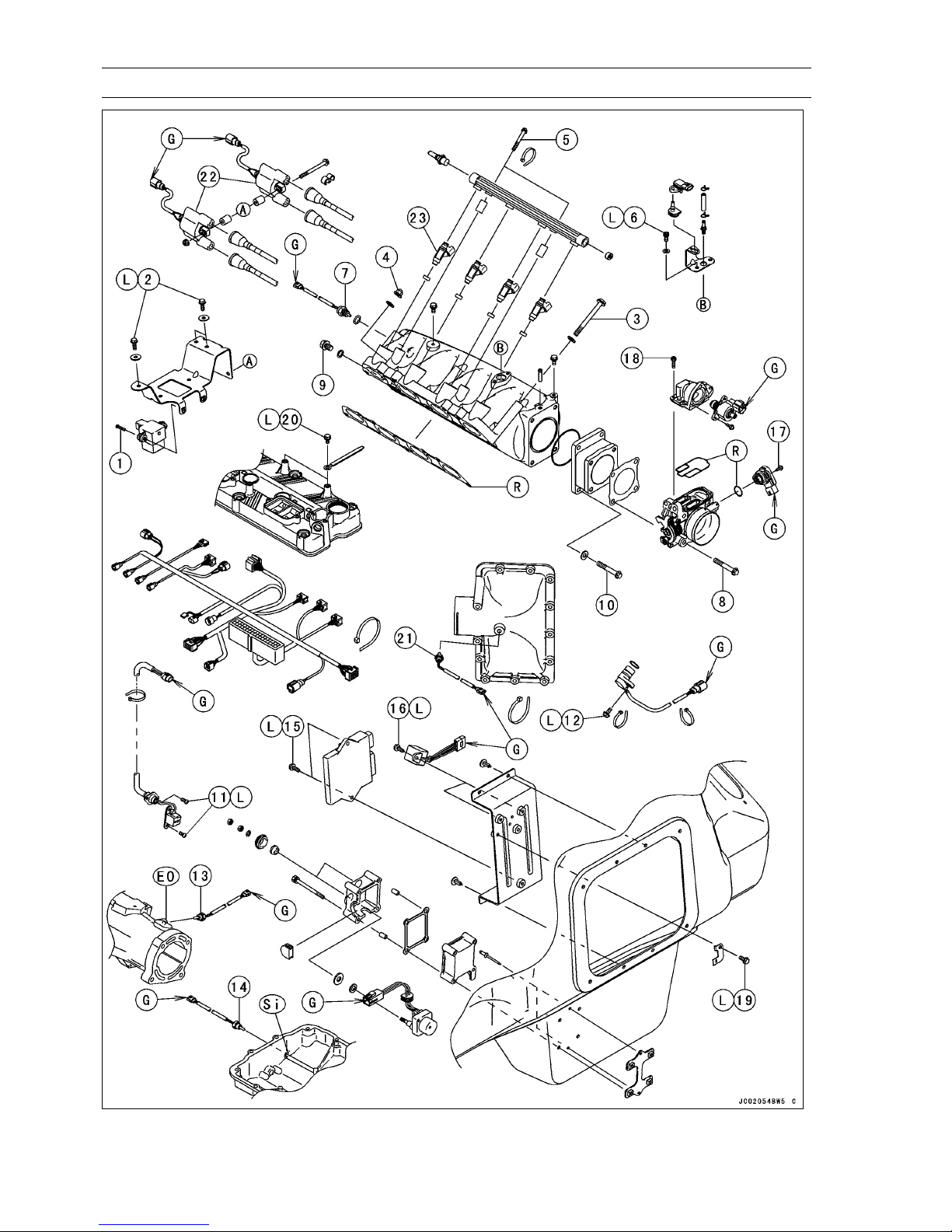
3-4 FUEL SYSTEM (DFI)
Exploded View
Page 65
Exploded View
FUEL SYSTEM (DFI) 3-5
No. Fastener
1 Vehicle-down Sensor Mounting Screws 1.5 0.15 13 in·lb
2 Bracket Mounting Bolts 8.8 0.90 78 in·lb L
3 Inlet Manifold Mounting Bolts 25 2.5 18
4 Inlet Manifold Mounting Nuts 20 2.0 14
5 Delivery Pipe Mounting Bolts 7.8 0.80 69 in·lb
6 Inlet Air Pressure Sensor Bracket Bolts 8.8 0.90 78 in·lb L
7 Inlet Air Temperature Sensor 20 2.0 14
8 Throttle Body Assy Mounting Bolts 20 2.0 14
9 Inlet Manifold Drain Plug 20 2.0 14
10 Throttle Body Assy Damper Bolts 20 2.0 78 in·lb
11 Crankshaft Sensor Screws 4.4 0.45 39 in·lb L
12 Camshaft Position Sensor Bolt 9.8 1.0 87 in·lb L
13 Water Temperature Sensor 15 1.5 11 see text
14 Oil Temperature Sensor 15 1.5 11 see text
15
ECU Mounting Bolts
16 Relay Bolts 2.5 0.25 22 in·lb L
17 Throttle Sensor Mounting Screws 2.0 0.20 18 in·lb
18
ISC Actuator Mounting Bolts
19 Fuse Bracket Bolt 2.5 0.25 22 in·lb L
20 Harness Bolts 8.8 0.90 78 in·lb L
21 Charging Temperature Sensor 15 1.5 11
22. Ignition Coils
23. Fuel Injectors
EO: Fill the hollow with the engine oil (10W-30).
G: Apply grease.
L: Apply a non-permanent locking agent.
R: Replacement Parts
Si: Fill the hollow with the specified silicone grease (Kawasaki Bond: 92137-1002).
N·m kgf·m ft·lb
3.0 0.3 27 in·lb L
4.9 0.50 43 in·lb
Torque
Remarks
Page 66
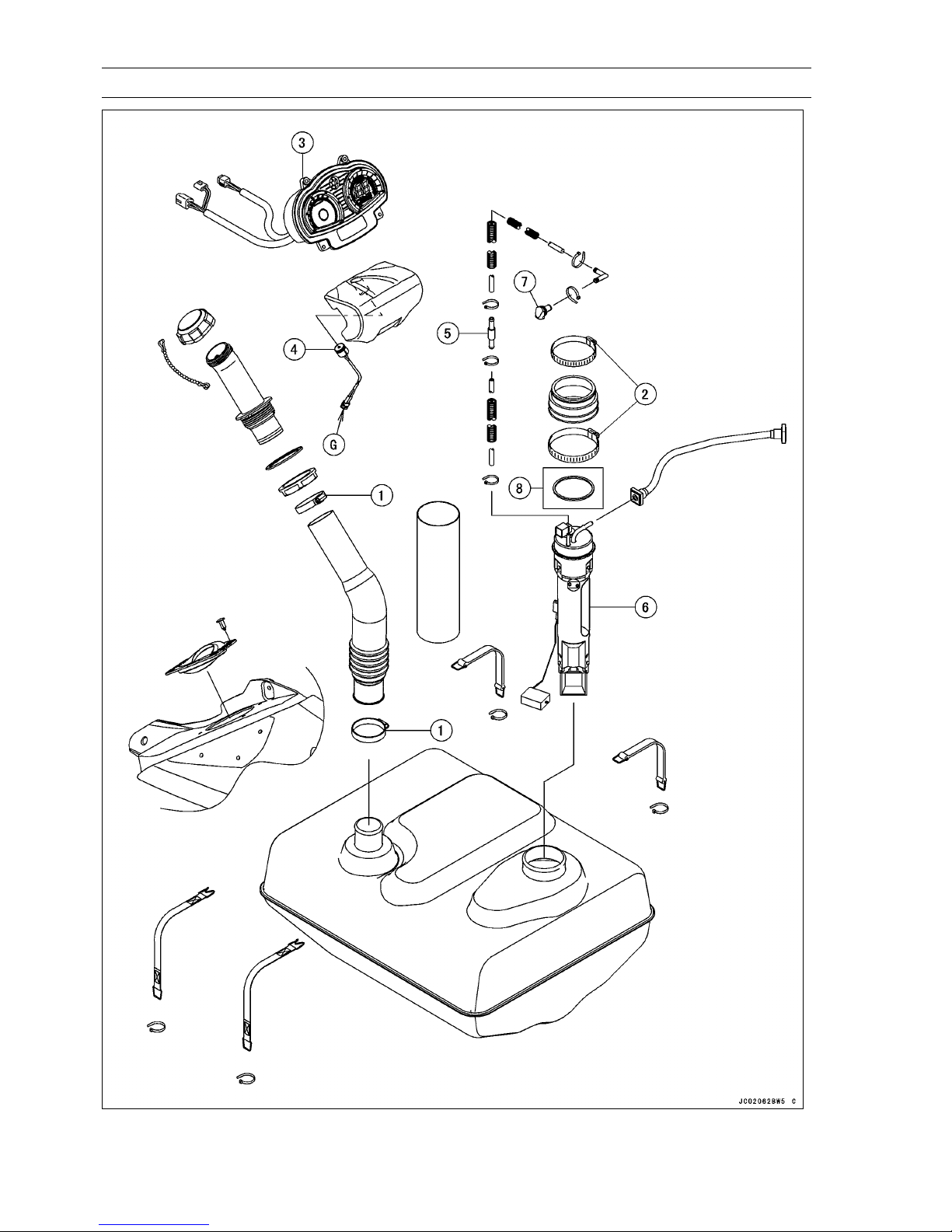
3-6 FUEL SYSTEM (DFI)
Exploded View
Page 67
Exploded View
FUEL SYSTEM (DFI) 3-7
No. Fastener
1 Fuel Filler Tube Clamp Screws 2.9 0.30 26 in·lb
2 Fuel Pump Holder Clamp Screws 2.9 0.30 26 in·lb
3. Meter Unit
4. Buzzer
5. Fuel Vent Check Valve
6. Fuel Pump
7. Install the grommet so that the hole of the grommet comes downward.
8. JT1500B7F Model
N·m kgf·m ft·lb
Torque
Remarks
Page 68
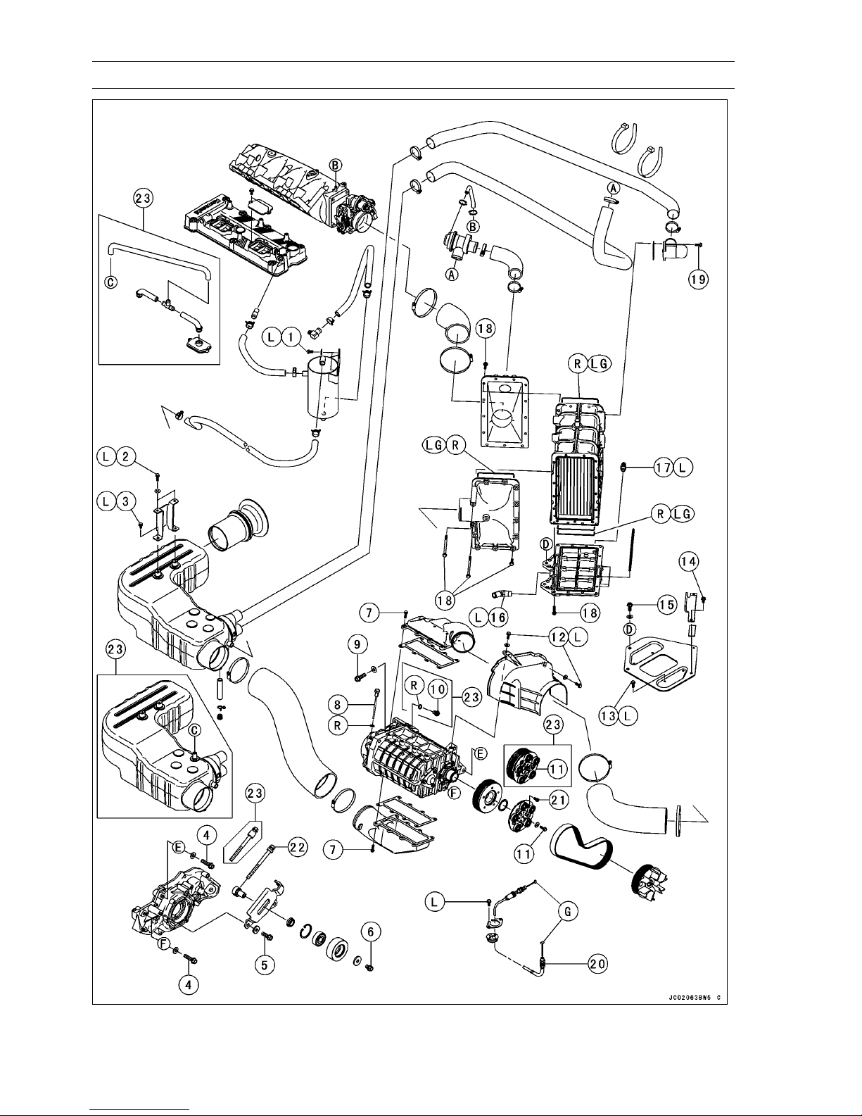
3-8 FUEL SYSTEM (DFI)
Exploded View
Page 69
Exploded View
FUEL SYSTEM (DFI) 3-9
No. Fastener
1 Oil Separator Tank Mounting Bolts 8.8 0.90 69 in·lb L
2 Air Box Bracket Bolts 8.8 0.90 69 in·lb L
3 Air Box Bolts 8.8 0.90 69 in·lb L
4 Rear Supercharger Bolts 45 4.6 33
5 Belt Tensioner Plate Bolts 45 4.6 33
6 Idler Bolt 30 3.1 22
7 Intake Pipe Bolts (IN/OUT) 7.8 0.80 69 in·lb
8 Gear Oil Level Gauge 19 1.9 14
9
Front S upercharger Bolts
10 Drain Bolt 19 1.9 14
11 Pulley Bolt 19 1.9 14
12 Belt Cover Bolts 4.9 0.50 43 in·lb L
13 Intercooler Plate Bolts 8.8 0.90 69 in·lb L
14 Intercooler Bracket Bolts 7.8 0.80 69 in·lb
15 Intercooler Mounting Bolts 30 3.1 22
16 Water Hose Joint 11 1.1 95 in·lb L
17 Water Hose Joint 20 2.0 14 L
18
Intercooler Cover Bolts
19 Blow off Valve Bolts 7.8 0.80 69 in·lb
20 Throttle C able Locknuts 20 2.0 14
21 Pulley Plate Bolts 15 1.5 11 L
22 Belt Tension Adjuster 3.0 0.31 27 in·lb
23. JT1500B7F Model
G: Apply grease.
L: Apply a non-permanent locking agent.
LG: Apply liquid gasket (Kawasaki Bond):92104-1063
R: Replacement Parts
N·m kgf·m ft·lb
45 4.6 33
10 1.0 89 in·lb
Torque
Remarks
Page 70
3-10 FUEL SYSTEM (DFI)
Specifications
Item Standard
Digital Fuel Injection System
Idle Speed 1 300 ±100 r/min (rpm) - both in and out of water
Throttle Assy:
Type
Bore 60 (2.36 in.)
ECU (Electronic Control Unit):
Make Mitsubishi Electric
Type
Operating range Engine speed range 100 ∼ 8 100 r/min (rpm)
Fuel Pressure (High Pressure Line):
Engine Idling approx. 294 kPa (3.0 kgf/cm², 43 psi)
Fuel Pump:
Type Impeller type
Discharge 83 mL or more for 3 seconds
Throttle Sensor:
Input Voltage 4.75 ∼ 5.25 V DC between R and BK/W leads
Output Voltage 1.08 ∼ 1.18 V DC between G/W and BK/W leads (at idle
Resistance 4 ∼ 6kΩ
Inlet Air Pressure Sensor:
Input Voltage 4.75 ∼ 5.25 V DC between R and BK/W leads
Output Voltage 3.75 ∼ 4.25 V DC between G/R and BK/W leads at standard
Inlet Air Temperature Sensor:
Output Voltage at ECU about 2.3 ∼ 2.6 V at 20°C (68°F)
Resistance 5.4 ∼ 6.6 kΩ at 0°C (32°F)
Water Temperature Sensor:
Resistance see Electrical System chapter
Output Voltage at ECU about 3 ∼ 4 V at 20°C (68°F)
Vehicle-down Sensor:
Detection Method
Detection A
Output Voltage
Fuel Injectors:
Type INP-281
Nozzle Ty pe One spray type with 4 holes
Resistance about 11.7 ∼ 12.3 Ω at 20°C (68°F)
Oil Temperature Sensor:
Resistance same to water temperature sensor
Output Voltage at ECU about 3 ∼ 4 V at 20°C (68°F)
ngle
Single type
Digital memory type, with built in IC igniter, sealed with
resin
throttle opening)
atmospheric pressure
2.26 ∼ 2.86 kΩ at 20°C (68°F)
0.29 ∼ 0.39 kΩ at 80°C (176°F)
Magnetic flux detection method
more than 110 ∼ 130° for each bank
with sensor tilted 110 ∼ 130° or more: 0.65∼ 1.35 V
with sensor arrow mark pointed up: 3.55 ∼ 4.45 V
Page 71
Specifications
Item Standard
Throttle Lever and Cables
Throttle Lever Free Play about 2 mm (0.08 in.)
FUEL SYSTEM (DFI) 3-11
Page 72
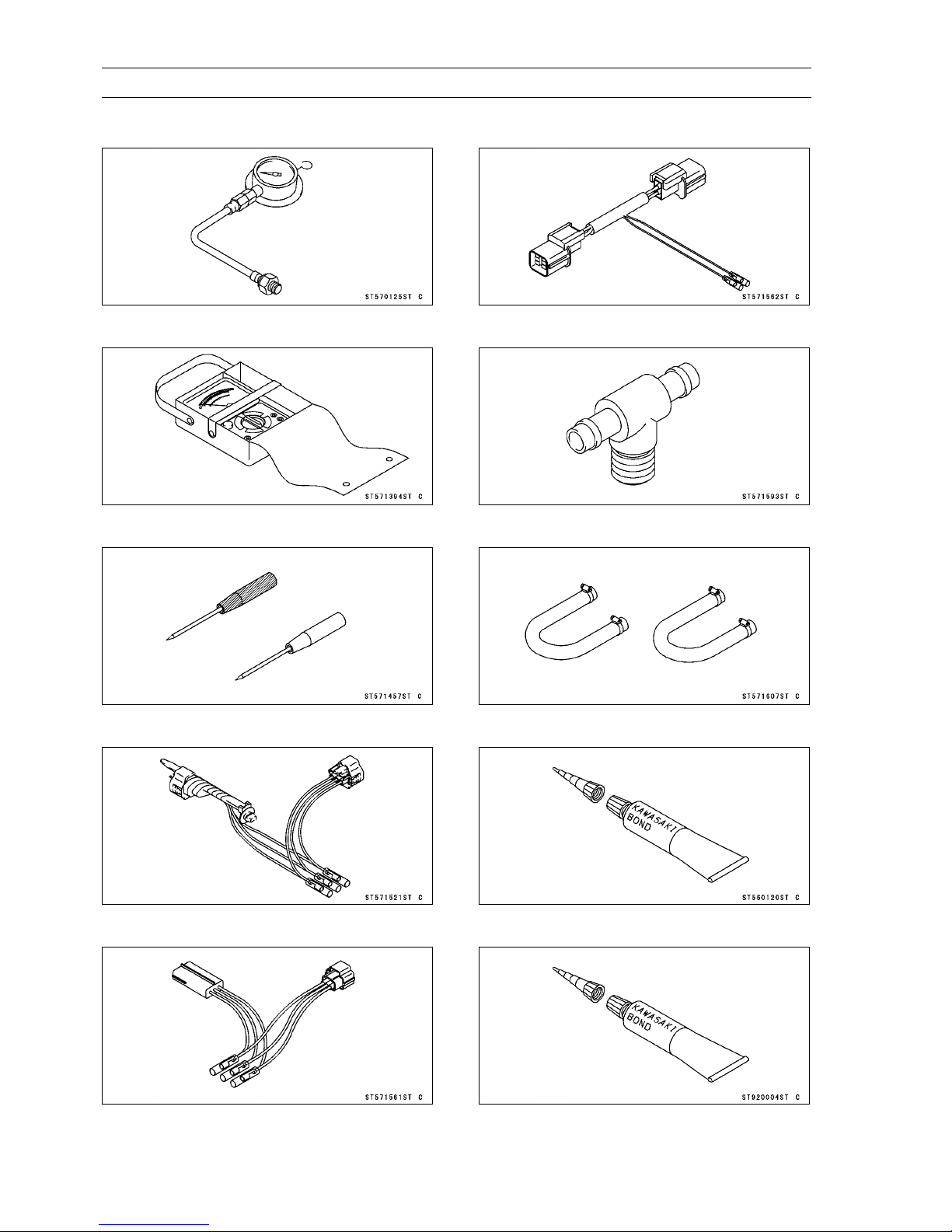
3-12 FUEL SYSTEM (DFI)
Special Tools and Sealant
Oil Pressure Gauge, 5 kgf/cm²:
57001-125
Hand Tester:
57001-1394
Needle Adapter Set:
57001-1457
Harness Adapter:
57001-1562
Fuel Pressure Gauge Adapter:
57001-1593
Fuel Hose:
57001-1607
Throttle Sensor Setting Adapter:
57001-1521
Sensor Harness Adapter:
57001-1561
Kawasaki Bond (Silicone Sealant):
56019-120
Kawasaki Bond (Silicone Sealant):
92104-0004
Page 73
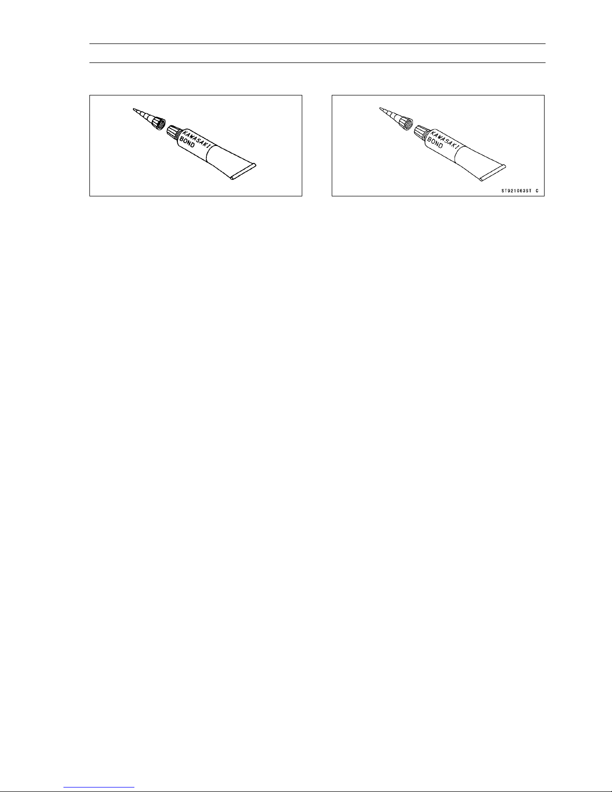
Special Tools and Sealant
FUEL SYSTEM (DFI) 3-13
Kawasaki Bond (Silicone Grease):
92137-1002
Kawasaki Bond (Liquid Gasket - Gray):
92104-1063
Page 74
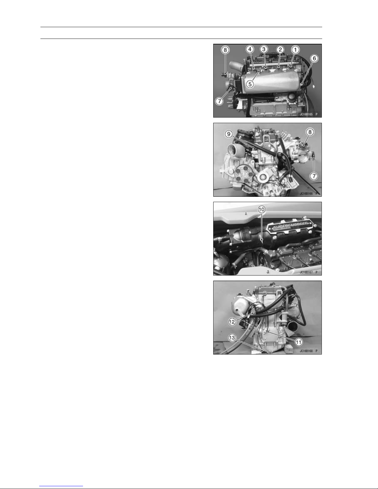
3-14 FUEL SYSTEM (DFI)
DFI Parts Location
1. Fuel Injector #1
2. Fuel Injector #2
3. Fuel Injector #3
4. Fuel Injector #4
5. Inlet Air Pressure Sensor
6. Inlet Air Temperature Sensor
7. Throttle Sensor
8. ISC (Idle Speed Controller)
9. Camshaft Position Sensor
10. Water Temperature Sensor
11. Crankshaft Sensor
12. Oil Pressure Switch
13. Oil Temperature Sensor
Page 75
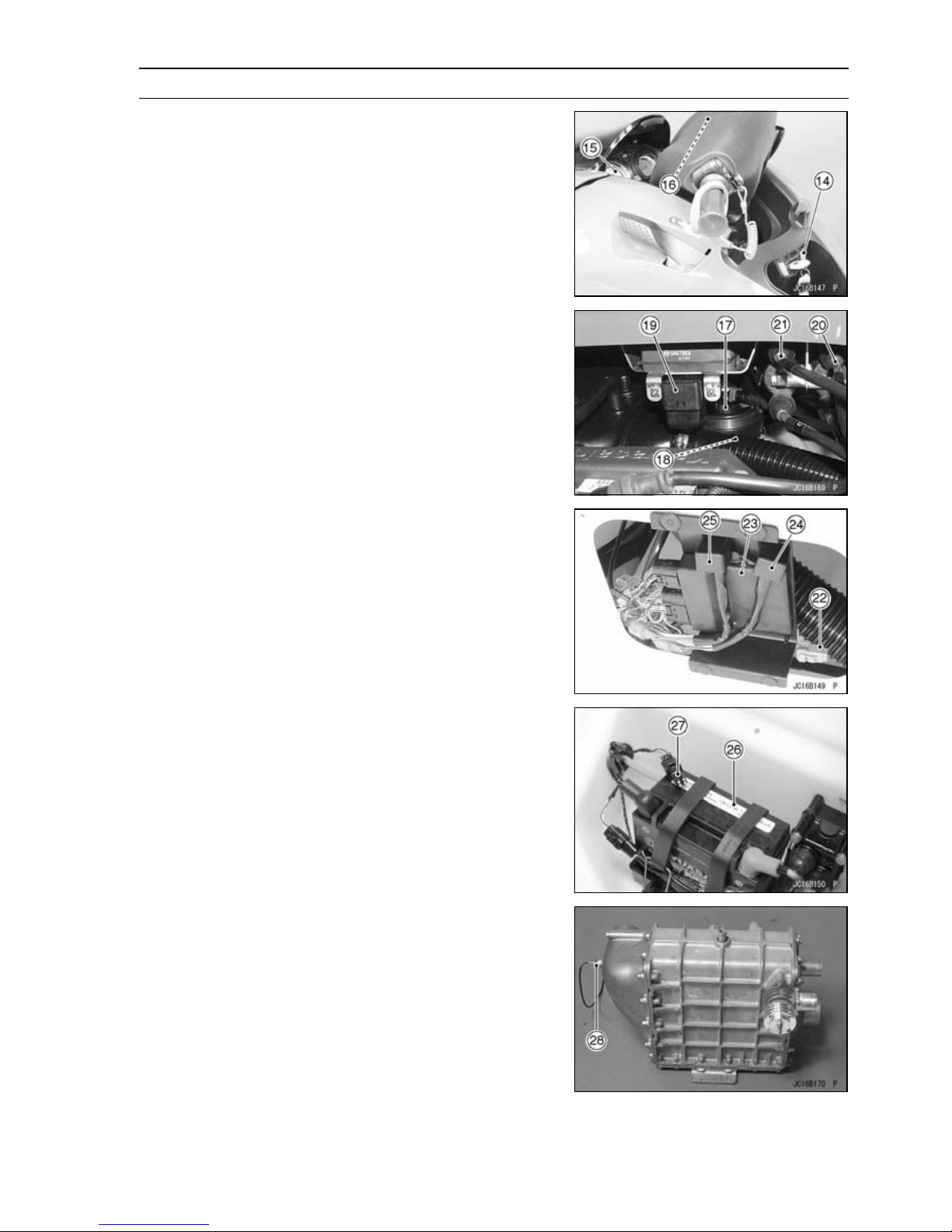
DFI Parts Location
14. Ignition Switch
15. Meter Unit
16. Buzzer
17. Fuel Pump
18. Fuel Level Sensor
19. Vehicle-down Sensor
20. Ignition Coil #1, #4
21. Ignition Coil #2, #3
22. Main Fuse 20 A
23. ECU (Electronic Control Unit)
24. ECU Main Relay
25. Fuel Pump Relay
26. Battery
27. Diagnosis Connector
28. Charging Temperature Sensor
FUEL SYSTEM (DFI) 3-15
Page 76
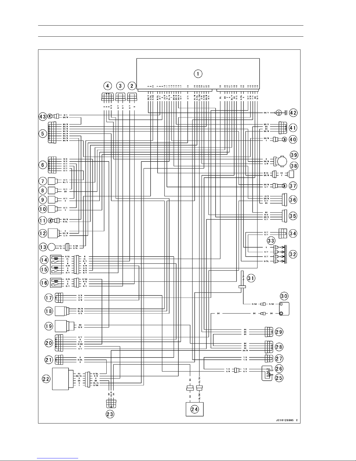
3-16 FUEL SYSTEM (DFI)
DFI System
DFI System Wiring Diagram
Page 77

DFI System
1. ECU
2. Joint Connector 8 (Vcc)
3. Joint Connector 7 (Vcc)
4. Joint Connector 6 (Power (5 V) - Sensor)
5. Joint Connector 5 (Ground - Sensor)
6. Joint Connector 4 (Power (12 V) - Injector)
7. Injector #4
8. Injector #3
9. Injector #2
10. Injector #1
11. Inlet Air Temperature Sensor
12. Inlet Air Pressure Sensor
13. Crankshaft Sensor
14. System Relay
15. Fuel Pump Relay
16. Main (ECU) Relay
17. Joint Connector 3 (Switch (12 V))
18. Vehicle-down Sensor
19. Fuel Pump
20. Joint Connector 2
21. Joint Connector 1
22. Ignition Switch (Immobilizer Amplifier)
23. Joint Connector 15 (Ground)
24. Multifunction Meter
25. Engine Stop Switch/Tether
26. Engine Start Switch
27. Joint Connector 13
28. Joint Connector 12 (Ground)
29. Joint Connector 11 (Ground)
30. Battery
31. Main Fuse 20 A
32. Spark Plugs
33. Ignition Coils
34. Joint Connector 10 (Ignition Coil (12 V))
35. Plug Nonuse
36. Plug Connector for DIAG and key Registration
37. Water Temperature Sensor
38. Camshaft Position Sensor (Exhaust)
39. Throttle Sensor
40. Oil Temperature Sensor
41. Joint Connector 9 (Ground Control)
42. Oil Pressure Switch
43. Charging Temperature Sensor
FUEL SYSTEM (DFI) 3-17
Page 78
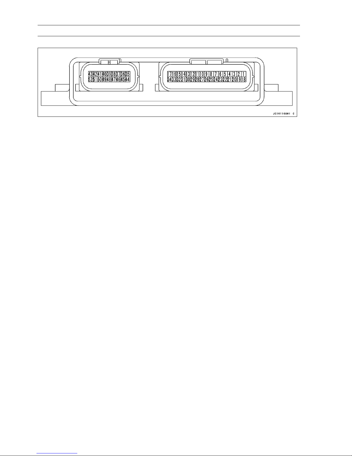
3-18 FUEL SYSTEM (DFI)
DFI System
Terminal Numbers of ECU Connectors
Terminal Names
1. ISC (Idle Speed Controller)
2. ISC (Idle Speed Controller)
3. Oil Pressure Switch
4. Unused
5. Crankshaft Sensor (–)
6. Unused (to unused connector)
7. Camshaft Position Sensor
8. Charging Temperature Sensor
9. Power Supply to Sensors
10. External Communication Line (Immobilizer
System)
11. Water Temperature Sensor
12. Immobilizer Amplifier
13. Oil Temperature Sensor
14. External Communication Line (*KDS)
15. Ground for Control System
16. External Communication Line (to unused
connector)
17. Battery (+)
18. ISC (Idle Speed Controller)
19. ISC (Idle Speed Controller)
20. Engine Stop Switch
21. Steering Position Sensor
22. Crankshaft Sensor (+)
23. Inlet Air Pressure Sensor
24. Unused
25. Unused
26. Vehicle-down Sensor
*KDS (Kawasaki Diagnostic System)
KDS that runs on Windows personal computer (PC) diagnostic tool for watercraft with Kawasaki DFI
system.
27. Unused
28. Inlet Air Temperature Sensor
29. Meter (DIAG)
30. Throttle Sensor
31. Immobilizer Amplifier
32. Ground for Sensor
33. External Communication Line (to unused
connector)
34. Battery Monitor
35. Unused
36. System Relay (–)
37. Unused
38. Injector #3
39. Ground for Power
40. Main (ECU) Relay
41. Unused
42. Injector #1
43. Ignition Coil #1, #4
44. Main Switch (To Meter)
45. Entry Switch (to Immobilizer Amplifier)
46. Start Switch
47. Injector #4
48. Ground for Power
49. Fuel Pump Relay
50. Ignition Coil #2, #3
51. Injector #2
52. unused
Page 79
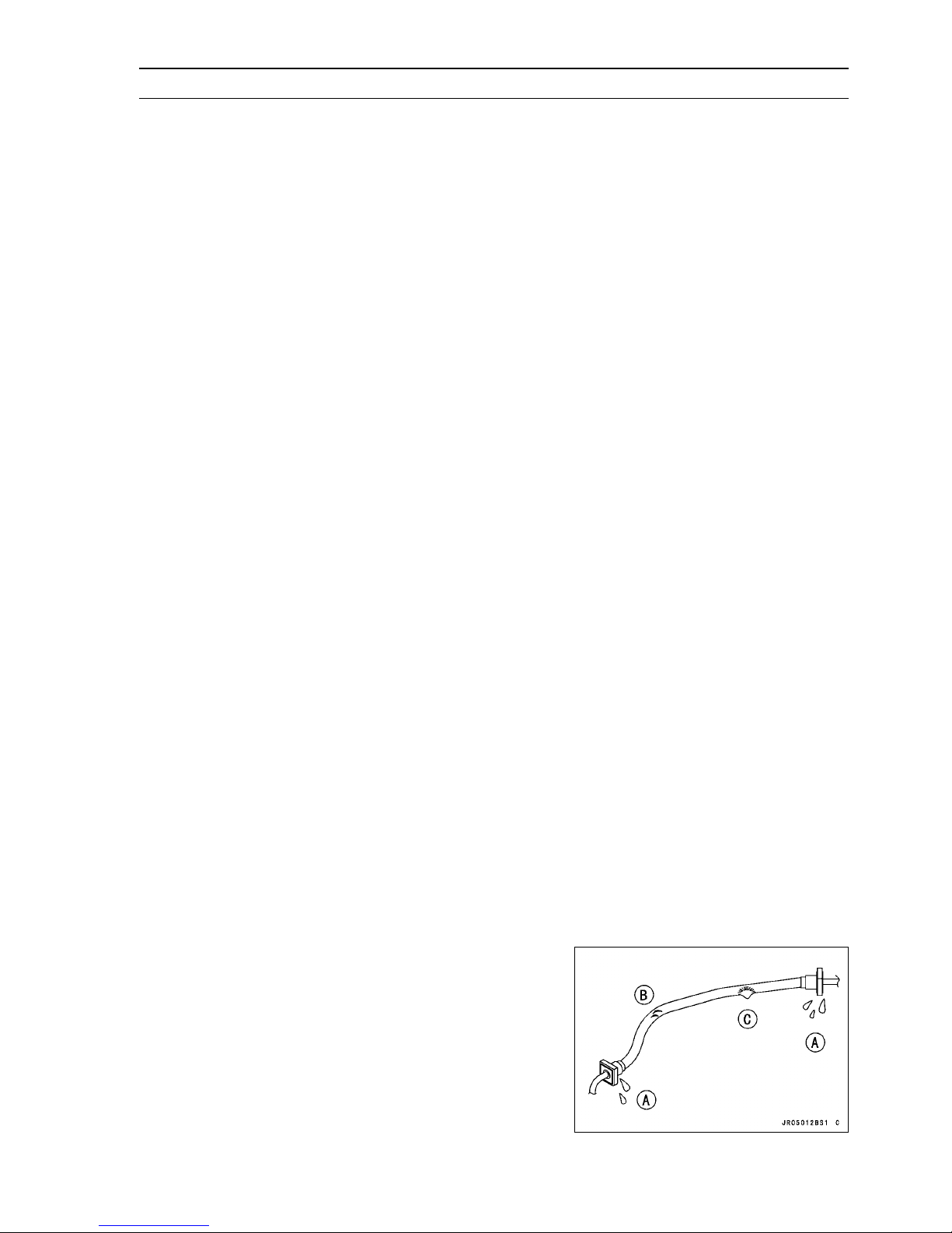
DFI Servicing Precautions
There are a number of important precautions that should
be followed servicing t he DFI system.
This DFI system is designed to be used with a 12 V sealed
○
battery as its power source. Do not use any other battery
except for a 12 V sealed battery as a power source.
Do not reverse the battery cable connections. This will
○
damage the ECU.
To prevent damage to the DFI parts, do not disconnect the
○
battery cables or any other electrical connections when
the ignition switch is on, or while the engine is running.
Take care not to short the leads that are directly con-
○
nected to the battery positive (+) terminal to the engine
ground.
When charging, remove the battery from the vehicle. This
○
is to prevent ECU damage by excessive voltage.
Whenever the DFI electrical connections are to be discon-
○
nected, first turn off the ignition switch. Conversely, make
sure that all the DFI electrical connections are firmly reconnected before starting the engine.
Do not turn the ignition switch ON while any of the DFI
○
electrical connectors are disconnected. The ECU memorizes service codes.
If a transceiver is installed on the vehicle, make sure that
○
the operation of the DFI system is not influenced by electric wave radiated from the antenna. Check operation of
the system with the engine at idle. Locate the antenna as
far as possible a way from the ECU.
When any fuel hose is disconnected, do not turn on the
○
ignition switch. Otherwise, the fuel pump will operate and
fuel will spout from the fuel hose.
Do not operate the fuel pump if the pump is completely
○
dry. This is to prevent pump seizure.
Before removing the fuel system parts, blow the outer sur-
○
faces of these parts clean with compressed air.
When any fuel hose is disconnected, fuel may spout out
○
by residual pressure in the fuel line. Cover the hose joint
with a piece of clean cloth to prevent fuel spillage.
When installing the fuel hoses, avoid sharp bending, kink-
○
ing, flattening or twisting, and route the fuel hoses with a
minimum of bending so that the fuel flow will not be obstructed.
Route the hoses according to Cable, Wire, and Hose
○
Routing section in the Appendix chapter.
FUEL SYSTEM (DFI) 3-19
The high pressure inside the fuel line can cause fuel to
○
leak [A] or the hose to burst. Bend and twist the fuel hose
while examining it.
Replace the hose if any cracks [B] or bulges [C] are no-
○
ticed.
Page 80
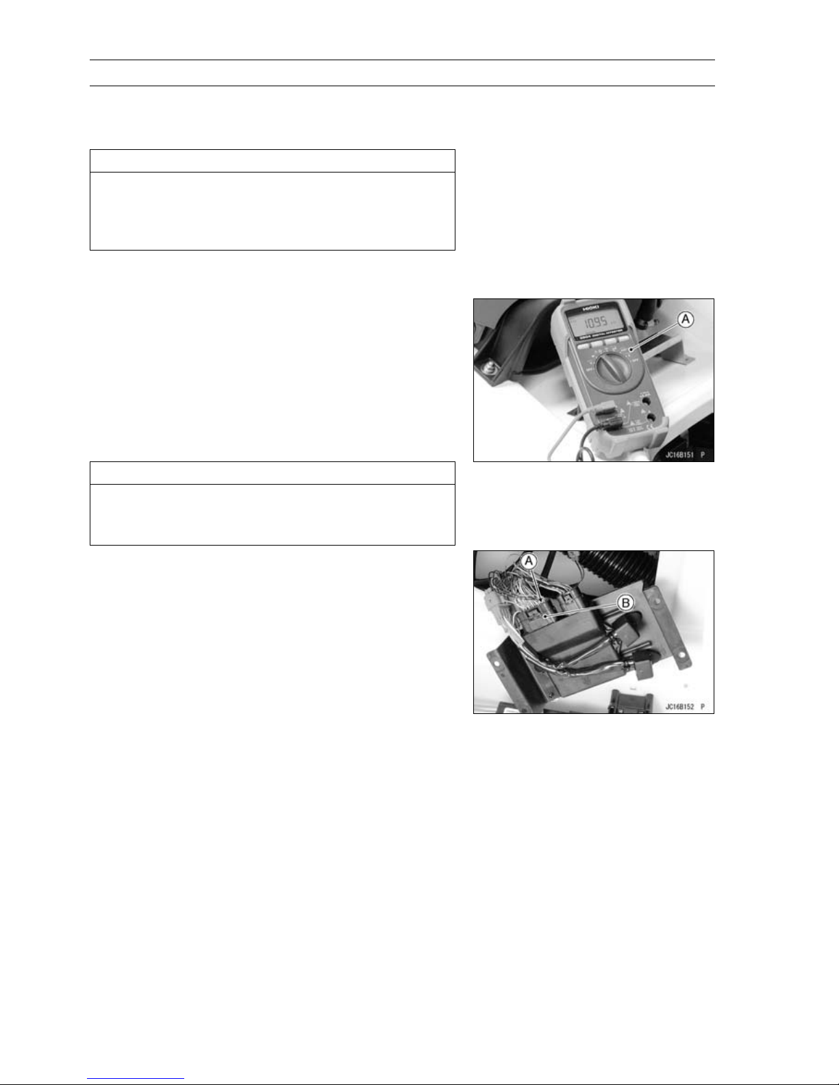
3-20 FUEL SYSTEM (DFI)
DFI Servicing Precautions
When checking the DFI parts, do not run the engine for
○
15 seconds or more without auxiliary cooling (see General
Information chapter).
CAUTION
If running the engine without the auxiliary cooling
for 15 seconds or more (even at idle speed), the rubber component relative to the Exhaust System may
be damaged.
Execute the auxiliary cooling securely in case that fre-
○
quent engine running is required.
When checking the DFI parts, use a digital meter which
•
can be read two decimal place voltage or resistance.
The DFI part connectors have seals, including the ECU.
○
When measuring the input or output voltage with the
connector joined, use the needle adapter set. Insert the
needle adapter inside the seal until the needle adapter
reaches the terminal.
Digital Meter [A]
Special Tool - Needle Adapter Set: 57001-1457
CAUTION
Insert the needle adapter straight along the terminal
in the connector to prevent short-circuit between
terminals.
After measurement, remove the needle adapters and ap-
○
ply silicone sealant to the seals [A] of the connector [B]
for waterproofing.
Silicone Sealant (Kawasaki Bond: 56019-120) - Seals
of Connector
Always check battery condition before replacing the DFI
•
parts. A fully charged battery is a must for conducting
accurate tests of the DFI system.
Do not directly connect a 12 V battery to a fuel injector.
•
Insert a resistor (5 ∼ 7 Ω) or a bulb (12 V, 3 ∼ 3.4 W) in
series between the battery and the injector.
Page 81
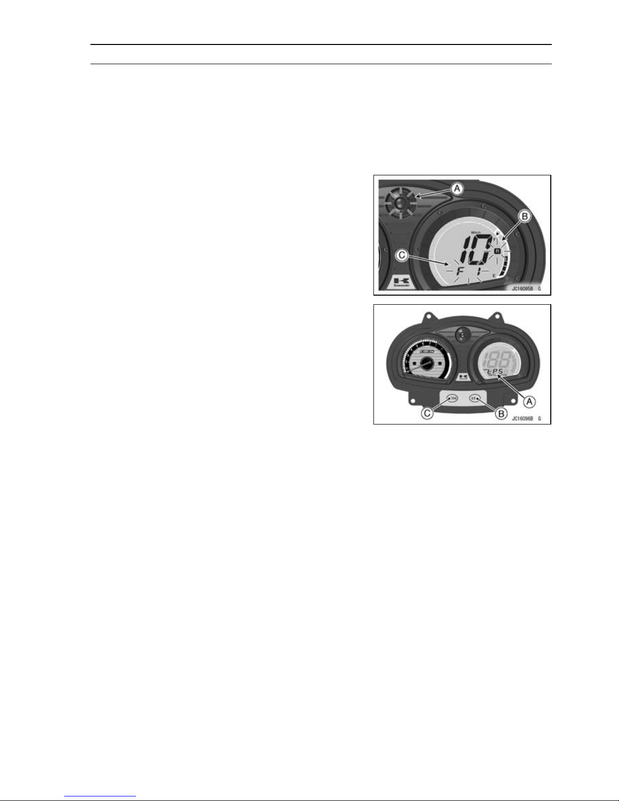
Self-Diagnosis
Self-diagnosis Outline
The self-diagnosis system has two modes and can be
switched to another mode.
[A]
Pushthe“SET”buttonwith“MODE”buttonatthe
same time for 3 seconds or more.
[B]
Push either “SET” or “MODE” button for more than
one second or more.
User Mode
This is a standard mode and enters automatically after
ignition switch ON. The ECU notifies the rider of troubles
in DFI system and ignition system by going on LED warning light [A] by flashing, the FI indicator [B] and “FI” character [C] when DFI system and ignition system parts are
faulty, and initiates fail-safe function. The buzzer sound
goes on. In case of serious troubles ECU stops the injection/ignition/starter motor operation. The buzzer sound can
be stopped by pushing either “SET” or “MODE” button.
Dealer Mode
The LCD in the meter unit displays service code character [A] to show the problem(s) which the DFI system and
ignition system has at the moment of diagnosis.
To enter the dealer mode push the “SET” button [B] with
•
“MODE” button [C] for 3 seconds or more.
Read the service code character in the LCD display. Re-
•
fer to the “Service Code (Character) Table” in the following
section.
To return the user mode push either “SET” or “MODE”
•
button for one second or more.
The service code character(s) will not be shown on the
•
LCD in the meter unit after the problems are solved.
FUEL SYSTEM (DFI) 3-21
Page 82
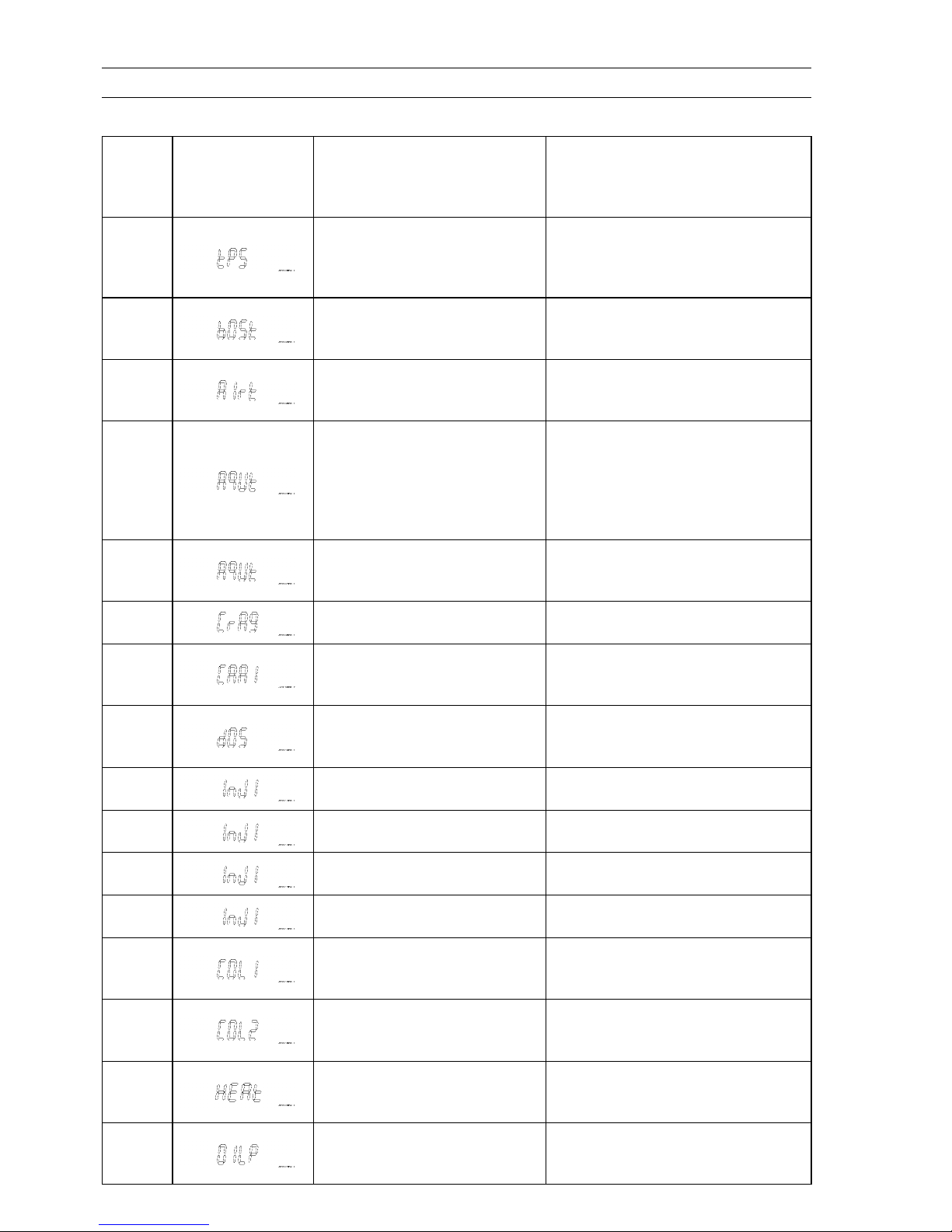
3-22 FUEL SYSTEM (DFI)
Self-Diagnosis
Service Code (Character) Table
Service
Code
(used in
ECU)
11
12
13
14
19
21
23
31
35
Service Code
Character
(displayed on
Meter Unit)
Possible Problems Fail-Safe Function
Throttle sensor malfunction,
wiring open or short
Inlet air pressure sensor
malfunction, wiring open or
short
Inlet air temperature sensor
malfunction, wiring open or
short
Water temperatur
malfunction, wiring open or
short
Charging temperature sensor
malfunction, wiring open or
short
Crankshaft sensor malfunction,
wiring open or short
Camshaft position sensor
malfunction, wiring open or
short
Vehicle-down sensor
malfunctio
short
Immobilizer amplifier
malfunction
n, wiring open or
e sensor
The ECU locks ignition timing into
the ignition timing at closed throttle
position and sets the DFI in the D-J
method (see Note 1).
The ECU sets the DFI in the α-N
method (see Note 2)
The ECU sets the inlet air
temperature at 40°
The ECU sets the water temperature
at 70°C. The ECU slows down the
engine speed less than 3 000 r/min
(rpm) by controlling the ignition
(Engine activates Slow Down
Mode).
The ECU slows down the engine
speed less than 3 000 r/min (rpm)
by controlling the ignition.
The ECU continues to ignite
cylinders in the same sequence
following the last good signal.
The ECU slows down the engine
speed less than 3 000 r/min (rpm)
by controlling the ignition.
.
C.
–
–
36 Key collation error –
45
46
51
52
71 Engine overheat
72 Engine oil pressure too low
Fuel pump relay malfunction,
wiring open
Fuel pump relay malfunction,
relay is stuck
Ignition coil #1, #4 malfunction,
wiring open or short
Ignition coil #2, #3 malfunction,
wiring open or short
–
–
The ECU shuts off the injectors
#1/#4 to stop fuel to the cylinders
#1/#4.
The ECU shuts off the injectors
#2/#3 to stop fuel to the cylinders
#2/#3.
The ECU slows down the engine
speed less than 3 000 r/min (rpm)
by controlling the ignition.
The ECU slows down the engine
speed less than 3 000 r/min (rpm)
by controlling the ignition.
Page 83
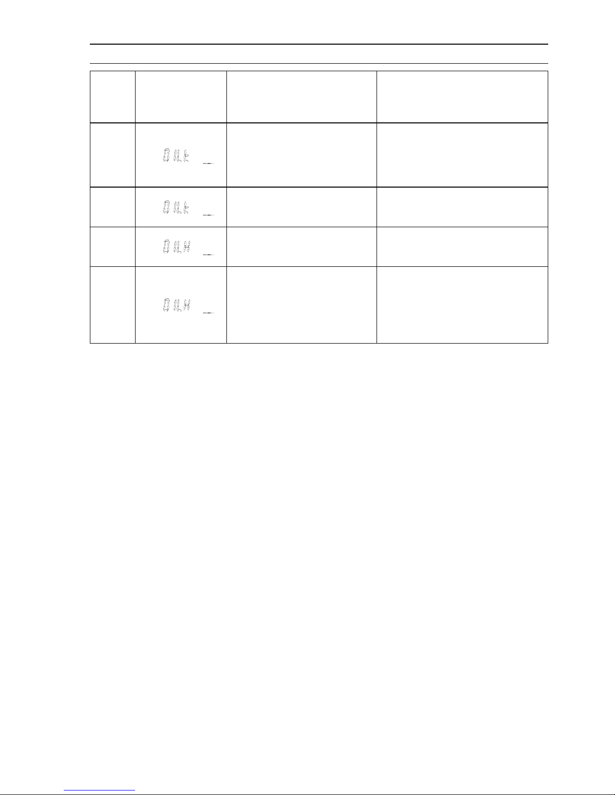
Self-Diagnosis
FUEL SYSTEM (DFI) 3-23
Service
Code
(used in
ECU)
73
75
76 Engine oil overheat
78
Note:
(1) D-J Method: the DFI control method from medium to heavy engine load. When the engine load
is light like at idling or low speed, the ECU determines the injection quantity by calculating from
the throttle vacuum (vacuum sensor output voltage) and engine speed (crankshaft sensor output
voltage).
(2) α-N Method: As the engine speed increases, and the engine load turns middle to heavy, the ECU
determines the injection quantity by calculating from the throttle opening (throttle sensor output
voltage) and the engine speed.
(3) If both throttle sensor system and inlet air pressure fails, the ECU locks ignition timing into the
igni
(4) The ECU may be involved in these problems. If all the parts and circuits are checked out good, be
sure to check the ECU for ground and power supply. If the ground and power supply are checked
good, replace the ECU.
Service Code
Character
(displayed on
Meter Unit)
tion timing at closed throttle position and sets the DFI in the α-N method.
Possible Problems Fail-Safe Function
Oil temperature sensor
malfunction, wiring open or
short
Main (ECU) relay and system
relay malfunction, wiring is
open or relay is stuck
Charging temperature too high
The ECU sets the oil temperature
at 60°C.
The ECU slows down the engine
speed less than 3 000 r/min (rpm)
by controlling the ignition.
The ECU slows down the engine
speed less than 3 000 r/min (rpm)
by controlling the ignition.
The ECU set the charging
temperature at 60°C. The ECU
slows down the engine speed less
than 3 000 r/min (rpm) by controlling
the ignition (Engine activates Slow
Down Mode).
–
Memory of Service Code (Character)
The service co
displayed in the meter. The past service codes can be confirmed by using the Kawasaki Diagnostic
System (see General Information chapter), and they can be erased.
des (characters) in the past are stored in the ECU. However, the characters cannot be
Page 84
3-24 FUEL SYSTEM (DFI)
Troubleshooting the DFI System
Sample Diagnosis Sheet
Rider name: Registration No. (license plate No.): Year of initial registration:
Model: Engine No.: Hull No.:
Date problem occurred: Mileage:
Environment when problem occurred.
Weather □ fine, □ cloudy, □ rain, □ snow, □ always, □ other:
Temperature □ hot, □ warm, □ cold, □ very cold, □ always
Problem
frequency
Altitude □
Warning
LED light, FI
character, FI
indicator
□ chronic, □ often, □ once
normal, □ high (about 1 000 m or more)
Watercraft conditions when problem occurred.
□
turn on immediately after ignition switch ON, and turn off after 1 ∼ 2 seconds
(normal).
□ lights blink after ignition switch ON, and stay on (DFI problem)
□ unlights (LED light, meter unit, ECU or its wiring fault).
□ sometimes lights up (probably wiring fault).
Starting
difficulty
□ starter motor not rotating.
□ starter motor rotating but engine doesn’t turn over.
□ starter m otor and engine don’t turn over.
□ no fuel flow (□ no fuel in tank, □ no fuel pump sound).
□ engine flooded (do not crank engine with throttle opened, which promotes
engine flooding).
□ no spark.
□ other:
□
Engine stalls
right after starting.
□ when opening throttle lever.
□ when closing throttle lever.
□ when moving off.
□ when stopping the watercraft.
□ when cruising.
□ other:
Poor running at
low speed
□ very low idle speed, □ very high idle speed, □ rough idle speed.
□ battery voltage is low (charge the battery).
□
spark plug loose (tighten it).
□ spark plug dirty, broken, or gap maladjusted (remedy it).
□ backfiring.
□ afterfiring.
□ hesitation when acceleration.
□ engine oil viscosity too high.
□ engine overheating.
□ other:
Page 85
Troubleshooting the DFI System
FUEL SYSTEM (DFI) 3-25
Poor running
or no power at
high speed
□ spark plug loose (tighten it).
□ spark plug dirty, broken, or gap maladjusted (remedy it).
□ spark plug incorrect (replace it).
□ knocking (fuel poor quality or incorrect).
□ engine overheating.
□ engine oil level too high.
□ engine oil viscosity too high.
□ other:
Page 86
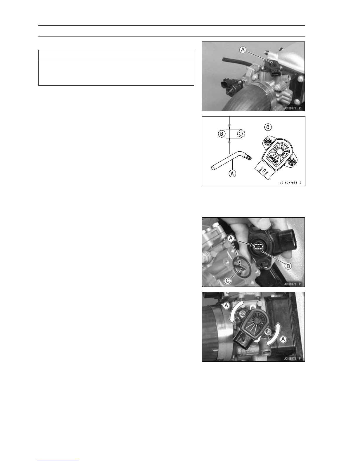
3-26 FUEL SYSTEM (DFI)
Throttle Sensor (Service Code/Character-11/tPS)
Throttle Sensor Removal/Adjustment
CAUTION
Never drop the throttle sensor [A], especially on a
hard surface. Such a shock to the sensor can damage it.
Remove:
•
Seat (see Seat Removal in the Hull/Engine Hood chapter)
Air filter (see air Filter Removal)
Use a Torx wrench [A] (T20, B = 3.86 mm (0.152 in.)) to
•
remove the throttle sensor mounting screws [C].
NOTE
In the engine compartment, there is not enough space
○
between the throttle sensor and hull to remove the Torx
screws. So use an L shape Torx wrench.
When installing the throttle sensor, note the following (In
•
the photo, the throttle sensor has been removed from the
throttle body for clarity).
Align [A] the projections [B] on the throttle sensor with the
○
throttle shaft [C] as shown when putting the throttle sensor
to the throttle body.
Turn the throttle sensor counterclockwise [A] a little and
○
temporarily tighten the throttle sensor mounting screws.
Page 87
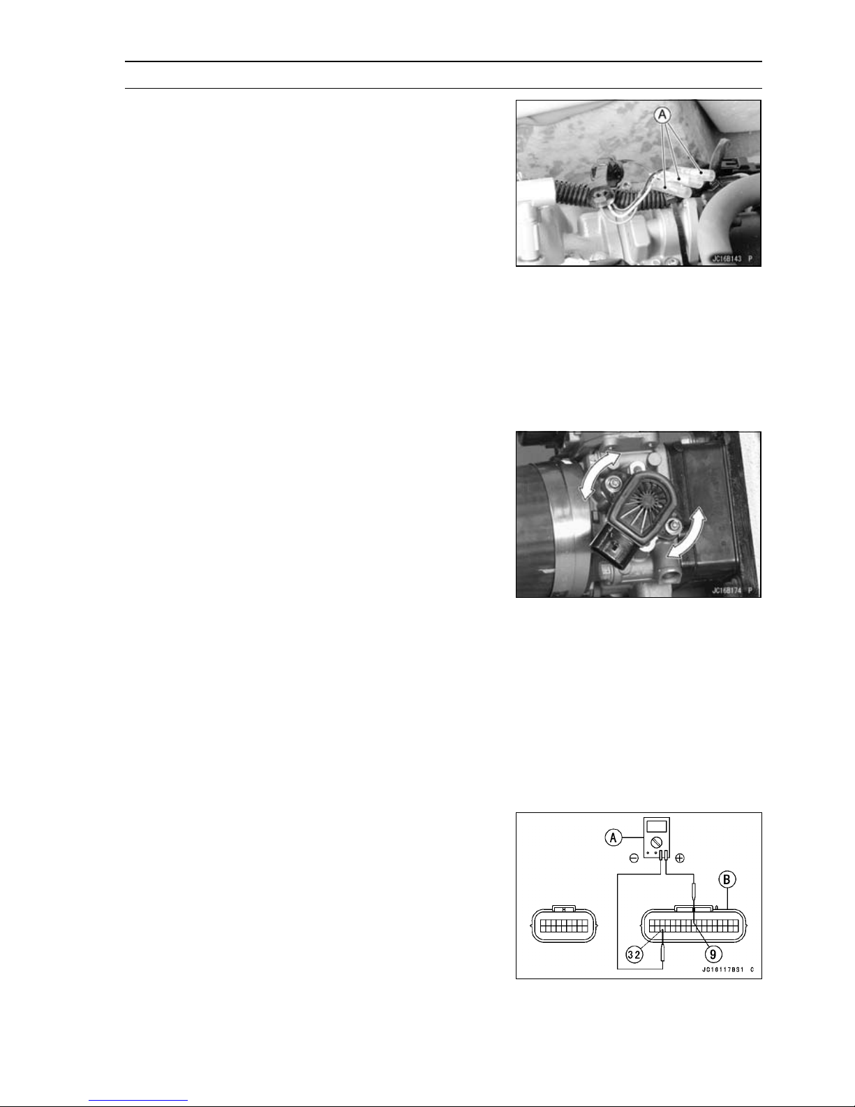
Throttle Sensor (Service Code/Character-11/tPS)
Adjust the throttle sensor positioning as follows.
•
Install the air filter temporarily.
○
After warming up the engine, check the idling speed.
○
Idle Speed
Standard: 1 300 ±100 r/min (rpm)
Stop the engine and turn the ignition switch OFF.
○
Disconnect the throttle sensor connector and connect the
○
throttle sensor setting adapter [A] between the harness
connector and throttle sensor connector.
Connect a digital meter to the sensor setting adapter
○
leads.
Special Tool - Throttle Sensor Setting Adapter: 57001
-1521
Throttle Sensor Output Voltage
Connections to Sensor
Meter (+)→ G/W lead
Meter (–)→ BK/W lead
Start the engine with idle speed.
○
Turn [A] the throttle sensor and bring the sensor output
○
voltage within the standard range.
FUEL SYSTEM (DFI) 3-27
Output Voltage at Sensor
Standard: 1.08 ∼ 1.18 V DC (at i dle throttle opening)
Tighten the throttle sensor mounting screws.
○
Torque - Throttle Sensor Mounting Screws: 2.0 N·m (0.20
kgf·m, 18 in·lb)
Recheck the sensor output voltage is within the standard
○
range.
Stop the engine and turn the ignition switch OFF.
○
Remove the setting adapter and reconnect the throttle
○
sensor connector.
Input Voltage Inspection
NOTE
Be sure the battery is fully charged.
○
Turn the ignition switch OFF.
•
Remove the ECU (see ECU Removal). Do not disconnect
•
the ECU connector.
Connect a digital voltmeter [A] to the connector [B], using
•
the needle adapter set.
Special Tool - Needle Adapter Set: 57001-1457
Throttle Sensor Input Vo ltage
Connections to ECU
Meter (+)→ R lead (terminal 9)
Meter (–)→ BK/W lead (terminal 32)
Page 88
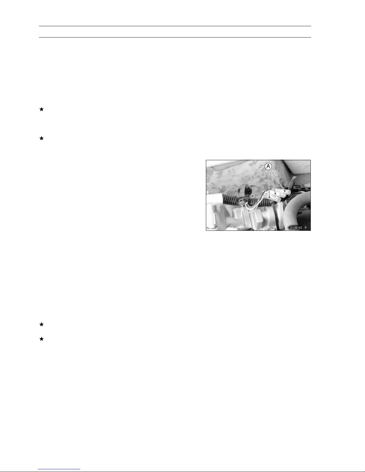
3-28 FUEL SYSTEM (DFI)
Throttle Sensor (Service Code/Character-11/tPS)
Turn the ignition switch ON and push the lanyard key un-
•
der the stop button.
Pushing the start button, run the engine 5 ∼ 6 seconds at
•
idling to measure the sensor input voltage.
Wait 15 seconds before using the starter again.
○
Input Voltage at ECU
Standard: 4.75 ∼ 5.25 V DC
Turn the ignition switch OFF.
•
If the reading of input voltage is less than the standard,
check the ECU for its ground, power supply and wiring
shorted. If the ground, power supply and wiring are good,
replace the ECU.
If the input voltage is within the standard range, check the
input voltage at the throttle sensor connector.
Remove the air filter temporarily (see Air Filter Removal).
•
Disconnect the throttle sensor connector and connect the
•
setting adapter [A] between the harness connector and
throttle sensor connector.
Connect a digital meter to the setting adapter leads.
•
Special Tool - Throttle Sensor Setting Adapter: 57001
-1521
Throttle Sensor Input Voltage
Connections to Sensor
Meter (+)→ Rlead
Meter (–)→ BK/W lead
Install the air filter.
•
Turn the ignition switch ON and push the lanyard key un-
•
der the stop button.
Pushing the start button, run the engine 5 ∼ 6 seconds at
•
idling to measure the sensor input voltage.
Wait 15 seconds before using the starter again.
○
Input Voltage at Sensor
Standard: 4.75 ∼ 5.25 V DC
Turn the ignition switch OFF.
•
If the reading is out of the range, check the wiring (see
wiring diagram in this section).
If the reading is good, check the output voltage of the
sensor.
Page 89
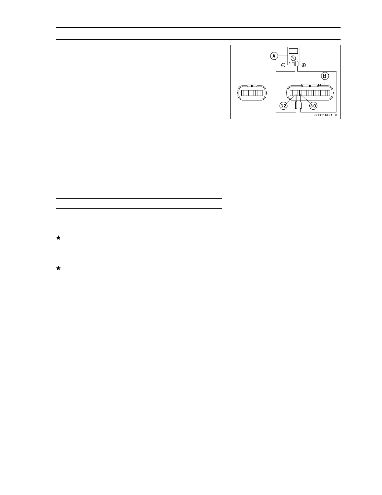
Throttle Sensor (Service Code/Character-11/tPS)
Output Voltage Inspection
Measure the output voltage at the ECU in the same way
•
as input voltage inspection. Note the following.
Digital Voltmeter [A]
Connector [B]
Special Tool - Needle Adapter Set: 57001-1457
Throttle Sensor Output Voltage
Connections to ECU
Meter (+) → G/W lead (terminal 30)
Meter (–) → BK/W lead (terminal 32)
Start the engine.
•
Check idle speed to ensure throttle opening is correct.
•
Idle Speed
Standard: 1 300 ±100 r/min (rpm)
Measure the sensor output voltage with the idle speed.
•
Output Voltage at ECU
Standard: 1.08 ∼ 1.18 V DC (at idle throttle opening)
FUEL SYSTEM (DFI) 3-29
CAUTION
Never drop the throttle sensor especially on a hard
surface. A shock to the sensor can damage it.
If the output voltage is within the s tandard range, check
the ECU for a good ground, and power supply (see ECU
Power Supply Inspection). If the ground and power sup-
ply are good, replace the ECU.
If the output voltage is far out of the standard range (e.g.
when the wiring is open, the reading is 0 V), check the
output voltage at the sensor connector.
Page 90
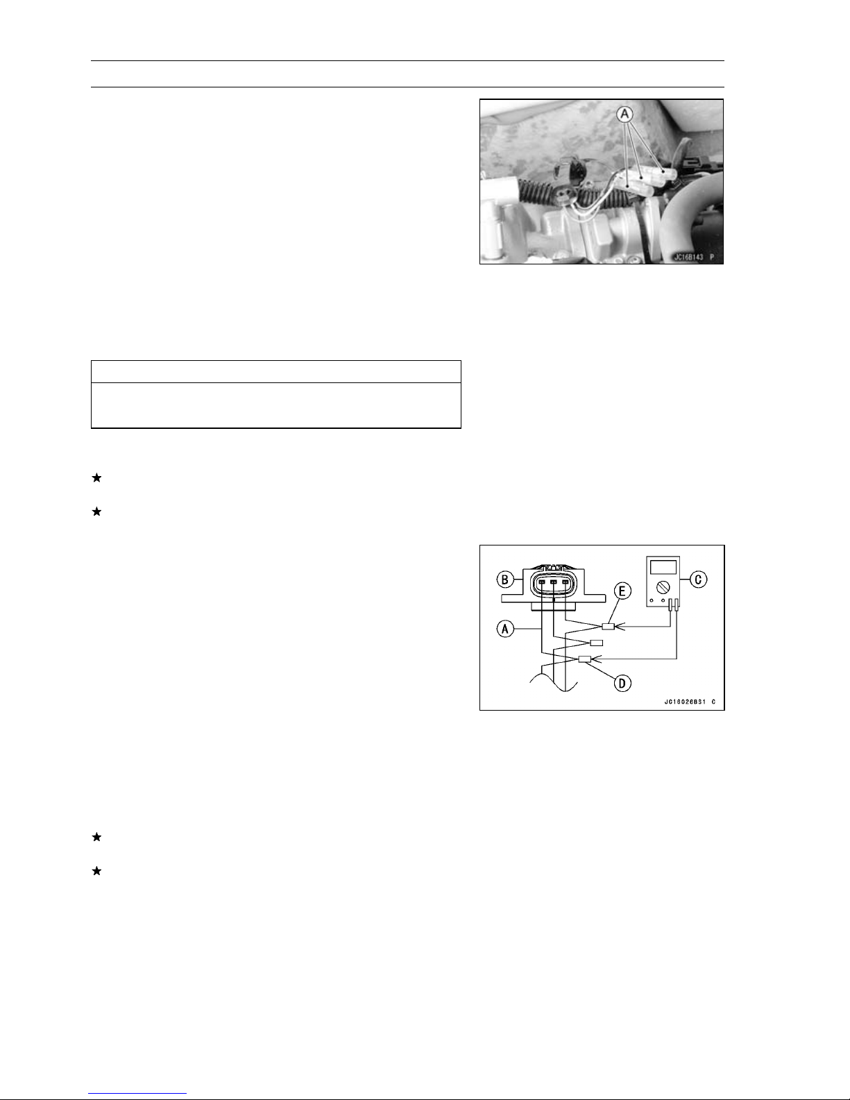
3-30 FUEL SYSTEM (DFI)
Throttle Sensor (Service Code/Character-11/tPS)
Disconnect the throttle sensor connector and connect the
•
setting adapter [A] between the harness connector and
throttle sensor connector.
Connect a digital meter to the setting adapter leads.
•
Special Tool - Throttle Sensor Setting Adapter: 57001
-1521
Throttle Sensor Output Voltage
Connections to Sensor
Meter (+) → G/W lead
Meter (–) → BK/W lead
Measure the sensor output voltage with the idle speed.
•
Output Voltage at Sensor
Standard: 1.08 ∼ 1.18 V DC (at idle throttle opening)
CAUTION
Never drop the throttle sensor, especially on a hard
surface. A shock to the sensor can damage it.
After throttle sensor voltage inspection, remove the set-
•
ting adapter.
If the reading is out of the standard range, inspect the
throttle sensor resistance.
If the output voltage is normal, check the wiring for continuity (see next diagram).
Resistance Inspection
Turn the ignition switch OFF.
•
Remove:
•
Air F ilter (see Air Filter Removal)
Disconnect the throttle sensor connector and connect the
•
setting adapter [A] to the throttle sensor [B].
Special Tool - Throttle Sensor Setting Adapter: 57001
-1521
Do not connect the harness connector.
○
Connect a digital meter [C] to the harness adapter leads.
•
Measure the throttle sensor resistance.
•
Throttle Sensor Resistance
Connections to
Harness Adapter:
Standard: 4 ∼ 6kΩ
If the reading is out of the range, replace the throttle body
assy.
If the reading is within the range, but the problem still
exists, replace the ECU.
R lead [D] ←→ BK/BL lead [E]
Page 91
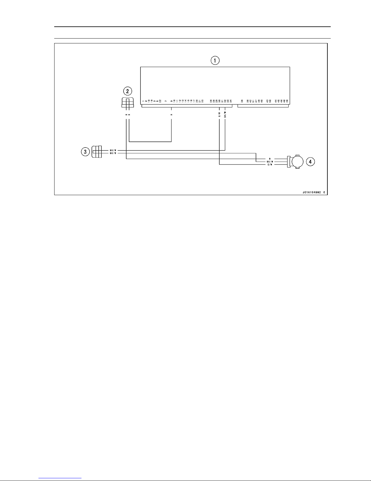
Throttle Sensor (Service Code/Character-11/tPS)
FUEL SYSTEM (DFI) 3-31
1. ECU
2. Joint Connector 6 (Power (5 V) - Sensor)
3. Joint Connector 5 (Ground - Sensor)
4. Throttle Sensor
Page 92
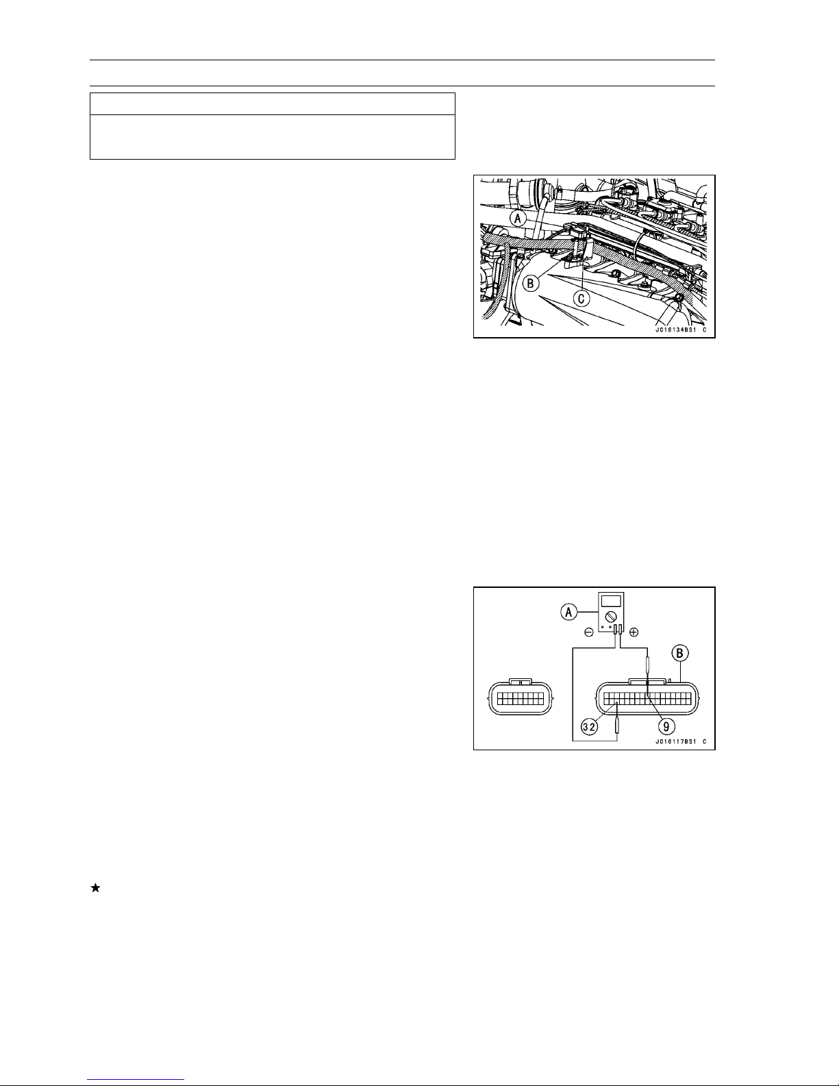
3-32 FUEL SYSTEM (DFI)
Inlet Air Pressure Sensor (Service Code/Character-12/bOSt)
CAUTION
Never drop the sensor, especially on a hard surface.
Such a shock to the part can damage it.
Inlet Air Pressure Sensor Removal
Turn the ignition switch off.
•
Remove:
•
Seat (see Seat Removal in the Hull/Engine Hood chapter)
Inlet Air Pressure Sensor Connector [A]
Hose [B] (Disconnect)
Inlet Air Pressure Sensor [C]
Inlet Air Pressure Sensor Installation
Install the vacuum hose.
•
Put the inlet air pressure sensor in the stay plate of the
•
inlet manifold.
Input Voltage Inspection
NOTE
Be sure the battery is fully charged.
○
The inspection is the same as “Input Voltage Inspection”
○
of the throttle sensor.
Turn the ignition switch OFF.
•
Remove the ECU (see ECU Removal). Do not disconnect
•
the ECU connector.
Connect a digital voltmeter [A] to the connector [B], with
•
the needle adapter set.
Special Tool - Needle Adapter Set: 57001-1457
Inlet Air Pressure Sensor Input Voltage
Connections to ECU
Meter (+)→ R lead (terminal 9)
Meter (–) → BK/W lead (terminal 32)
Turn the ignition switch ON and push the lanyard key un-
•
der the stop button.
Pushing the start button, run the engine 5 ∼ 6 seconds at
•
idling to measure the sensor input voltage.
Wait 15 seconds before using the starter again.
○
Input Voltage at ECU
Standard: 4.75 ∼ 5.25 V DC
Turn the ignition switch OFF.
•
If the reading is less than the standard, check the ECU for
its ground, power supply and wiring. If the ground, power
supply and wiring are good, replace the ECU.
Page 93
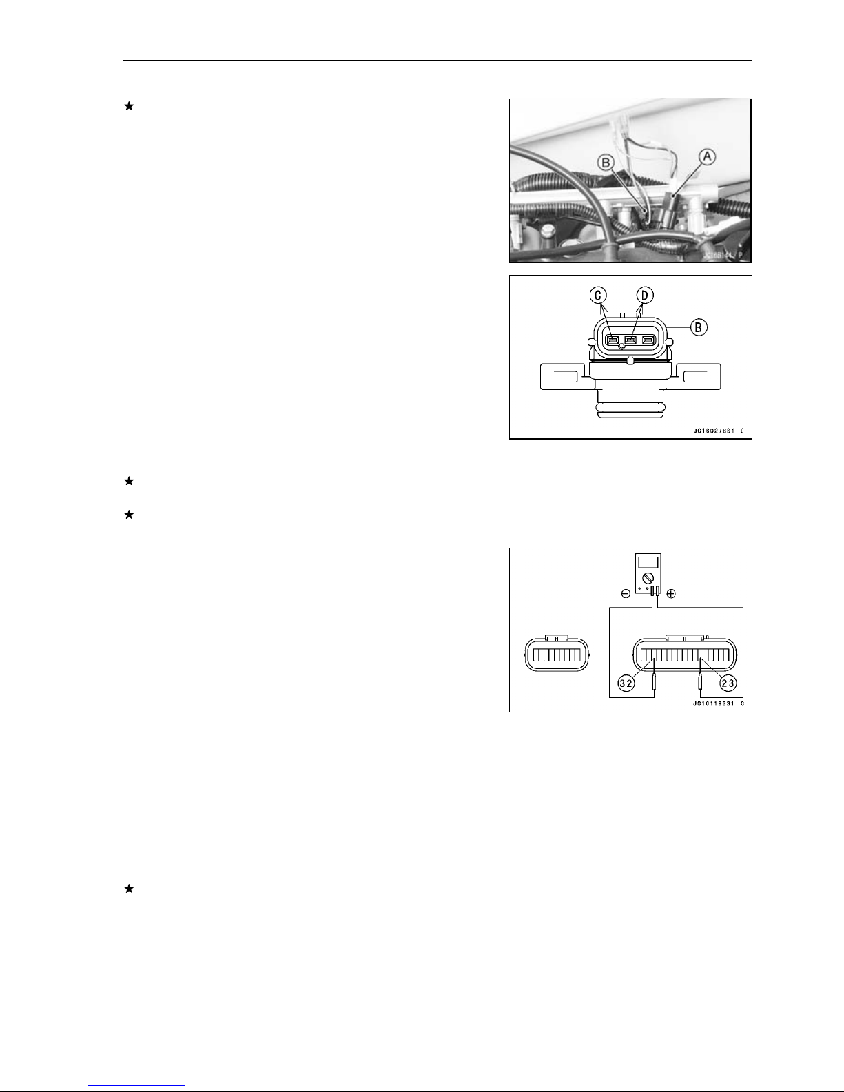
FUEL SYSTEM (DFI) 3-33
Inlet Air Pressure Sensor (Service Cod e/Character-12/bOSt)
If the reading is within the standard range, and check the
input voltage at the sensor connector.
Disconnect the inlet air pressure sensor connector and
•
connect the harness adapter [A] between the harness
connector and inlet air pressure sensor connector.
Connect a digital meter to the harness adapter leads.
•
[B] Inlet Air Pressure Sensor
Special Tool - Sensor Harness Adapter: 57001-1561
Inlet Air Pressure Sensor Input Voltage
Connections to Sensor
Meter (+) → Rlead[C]
Meter (–) → BK/W lead [D]
Turn the ignition switch ON and push the lanyard key un-
•
der the stop button.
Pushing the start button, run the engine 5 ∼ 6 seconds at
•
idling to measure the sensor input voltage.
Wait 15 seconds before using the starter again.
○
Input Voltage at Sensor Connector
Standard: 4.75 ∼ 5.25 V DC
Turn the ignition switch OFF.
•
If the reading is out of the standard range, check the
wiring (see Wiring Diagram in this section).
If the reading is good, the input voltage is normal. Check
the output voltage.
Output Voltage Inspection
Measure the output voltage at the ECU in the same way
•
as input voltage inspection. Note the following.
Inlet Air Pressure Sensor Output Voltage
Connections to ECU
Meter (+) → G/R lead (terminal 23)
Meter (–) → BK/W lead (terminal 32)
Output Voltage at ECU
Usable Range:
The output voltage changes according to the local at-
○
mospheric pressure.
The vacuum sensor output voltage is based on a nearly
○
perfect vacuum in the small chamber of the sensor. So,
the sensor indicates absolute vacuum pressure.
If the output voltage is within the usable range, check
the ECU for its ground, power supply and wiring. If the
ground, power supply and wiring are good, replace the
ECU.
3.75 ∼ 4.25 V DC at the standard
atmospheric pressure (101.32 kPa, 76
cmHg absolute)
NOTE
Page 94
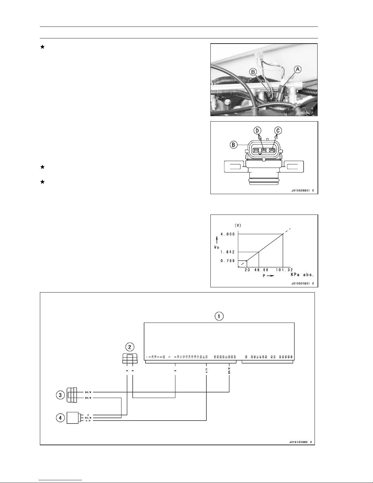
3-34 FUEL SYSTEM (DFI)
Inlet Air Pressure Sensor (Service Code/Character-12/bOSt)
If the output voltage is far out of the usable range, check
the output voltage at the sensor connector [A].
Measure the output voltage at the sensor in the same way
•
as input voltage inspection. Note the following.
[B] Inlet Air Pressure Sensor
Special Tool - Sensor Harness Adapter: 57001-1561
Inlet Air Pressure Sensor Output Voltage
Connections to Sensor
Meter (+) → G/R lead [C]
Meter (–) → BK/W lead [D]
Output Voltage at Sensor Connector
Usable Range:
If the output voltage is normal, check the wiring for continuity (see next diagram).
If the output voltage is out of the usable range, replace
the sensor.
Turn the ignition switch OFF.
•
Remove the sensor harness adapter.
•
3.75 ∼ 4.25 V DC at the standard
atmospheric pressure (101.32 kPa or
76 cmHg absolute)
Output Voltage Performance
(at Input Voltage: 4.75 ∼ 5.25 V)
P: Vacuum Pressure
Vo: Output Voltage
1. ECU
2. Joint Connector 6 (Power (5 V) - Sensor)
3. Joint Connector 5 (Ground - Sensor)
4. Inlet Air Pressure Sensor
Page 95
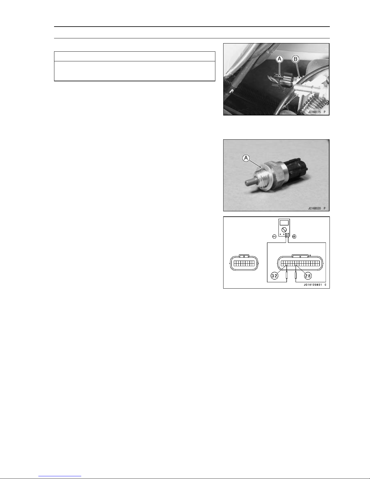
FUEL SYSTEM (DFI) 3-35
Inlet Air Temperature Sensor (Service Code/Character-13/AIrt)
Inlet Air Temperature Removal/Installation
CAUTION
Never drop the sensor, especially on a hard surface.
Such a shock to the sensor can damage it.
Disconnect the following to make service easy.
•
Spark Plug Caps
Fuel Hose
Air Bypass Hose (Upper Side)
Disconnect the connector [A] from the inlet air tempera-
•
ture sensor.
Remove the i nlet air temperature sensor [B] and washer.
•
Install the inlet air temperature sensor and washer [A].
•
Tighten:
•
Torque - Inlet Air Temperature Sensor: 20 N·m (2.0 kgf·m,
14 ft·lb)
Output Voltage Inspection
NOTE
Be sure the battery is fully charged.
○
Remove the ECU (see ECU Removal). Do not disconnect
•
the ECU connector.
Connect a digital voltmeter to the ECU connector, using
•
needle adapter set.
Special Tool - Needle Adapter Set: 57001-1457
Inlet Air Temperature Sensor Output Voltage
Connections to ECU Connector
Meter (+) → R/BL lead (terminal 28)
Meter (–) → BK/W lead (terminal 32)
Turn the ignition switch ON and push the lanyard key un-
•
der the stop button.
Pushing the start button, run the engine 5 ∼ 6 seconds at
•
idling to measure the sensor output voltage.
Wait 15 seconds before using the starter again.
○
Output Voltage at ECU
Standard:
The output voltage changes according to the inlet air
○
temperature.
about 2.3 ∼ 2.6 V at inlet air temperature
20°C (68°F)
NOTE
Turn the ignition switch OFF.
•
Page 96
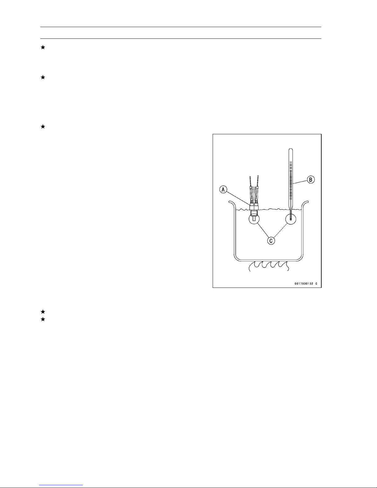
3-36 FUEL SYSTEM (DFI)
Inlet Air Temperature Sensor (Service Code/Character-13/AIrt)
If the output voltage is out of the specified, check the ECU
for its ground, and power supply (see ECU Power Supply
Inspection). If the ground and power supply are good,
replace the ECU.
If the output voltage is far out of the specified, check the
wiring (see next diagram).
Remove the needle adapter set, and apply silicone
•
sealant to the s eals of the connector for waterproofing.
Silicone Sealant (Kawasaki Bond: 56019-120) -Seals
of ECU Connectors
If the wiring is good, check the sensor resistance.
Sensor Resistance Inspection
Remove the inlet air temperature sensor (see Inlet Air
•
Temperature Sensor Removal).
Suspend the s ensor [A] in a container of machine oil so
•
that the heat-sensitive portion and threaded portion are
submerged.
Suspend a thermometer [B] with the heat-sensitive por-
•
tion [C] located in almost the same depth with the sensor.
NOTE
The sensor and thermometer must not touch the con-
○
tainer side or bottom.
Place the container over a source of heat and gradually
•
raise the temperature of the oil while stirring the oil gently
for even temperature.
Using a digital meter, measure the internal resistance
•
of the sensor across the terminals at the temperatures
shown in the table.
Inlet Air Temperature Sensor Resistance
Standard: 5.4 ∼ 6.6 kΩ at 0°C (32°F)
2.26 ∼ 2.86 kΩ at 20°C (68°F)
0.29 ∼ 0.39 kΩ at 80°C (176°F)
If the measurement is out of the range, replace the sensor.
If the measurement is within the specified, replace the
ECU.
Page 97
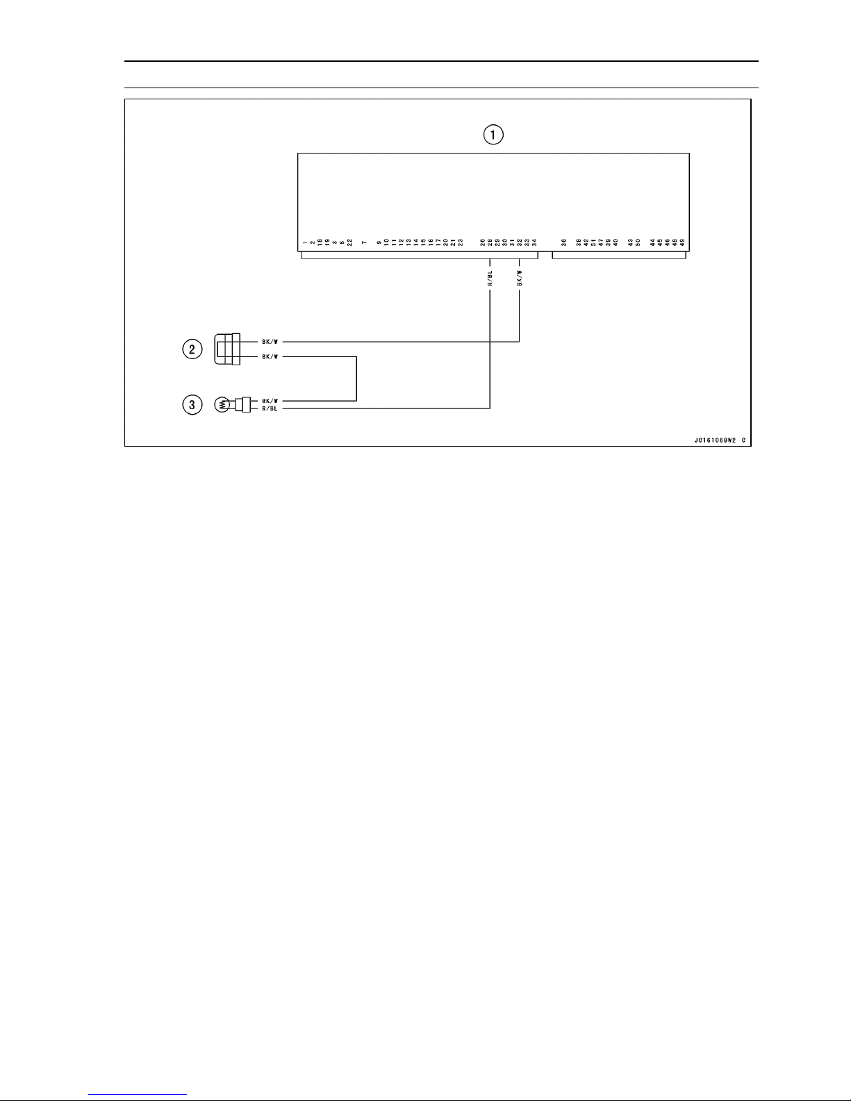
FUEL SYSTEM (DFI) 3-37
Inlet Air Temperature Sensor (Service Code/Character-13/AIrt)
1. ECU
2. Joint Connector 5 (Ground - Sensor)
3. Inlet Air Temperature Sensor
Page 98
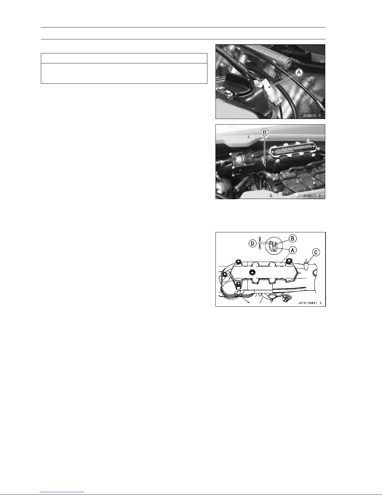
3-38 FUEL SYSTEM (DFI)
Water Temperature Sensor (Service Code/Character-14/AqUt)
Water Temperature Sensor Removal/Installation
CAUTION
Never drop the sensor, especially on a hard surface.
Such a shock to the sensor can damage it.
Disconnect the sensor connector [A], and unscrew the
•
water temperature sensor [B].
When installing the water temperature sensor, remove the
•
exhaust pipe for the engine oil filling in the hollow of the
exhaust manifold.
Fill the hollow of the exhaust pipe [A] with the engine oil
•
(10W-30) [B] as shown, before installing the w ater temperature sensor [C].
[D] 5 mm (0.2 in.)
Tighten:
•
Torque - Water Temperature Sensor: 15 N·m (1.5 kgf·m, 11
ft·lb)
Output Voltage Inspection
NOTE
Be sure the battery is fully charged.
○
Remove the ECU (see ECU Removal). Do not disconnect
•
the connector.
Page 99
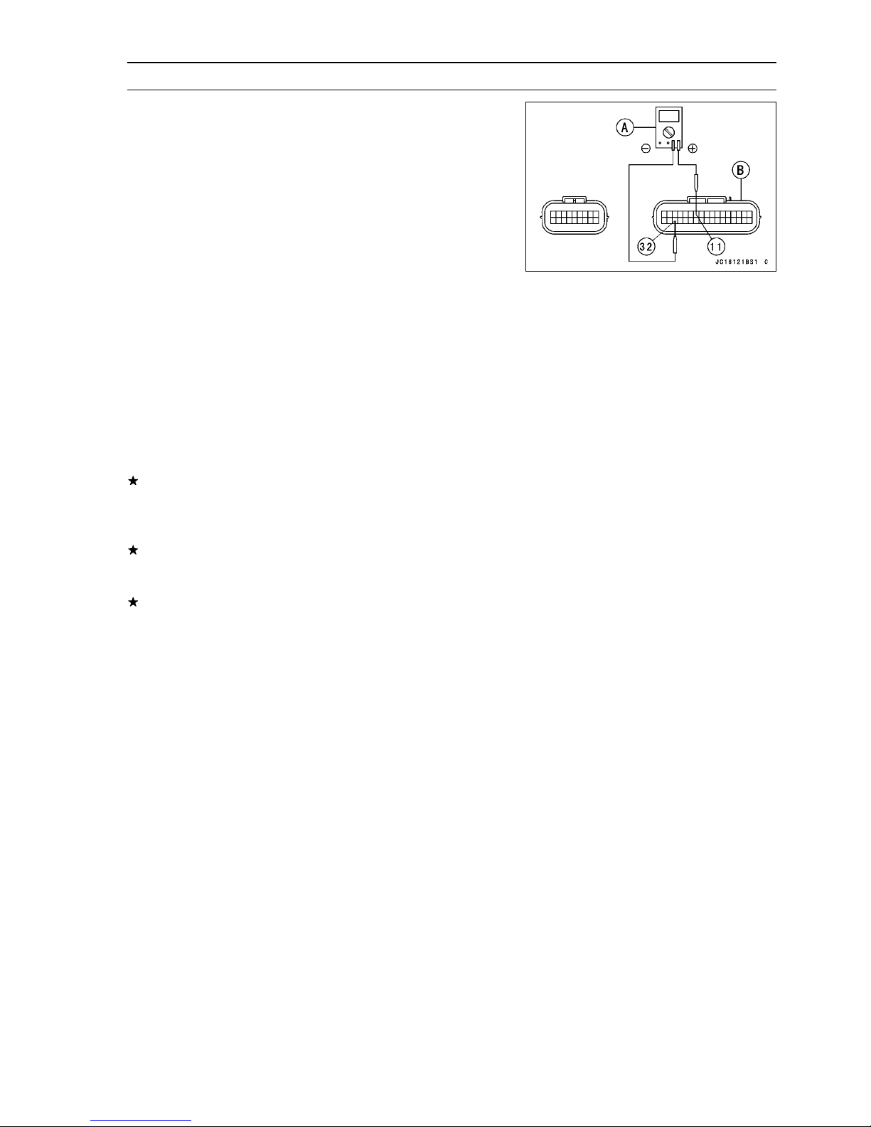
FUEL SYSTEM (DFI) 3-39
Water Temperature Sensor (Service Code/Character-14/AqUt)
Connect a digital voltmeter [A] to the ECU connector [B],
•
with the needle adapter set.
Special Tool - Needle Adapter Set: 57001-1457
Water Temperature Sensor Output Voltage
Connections to ECU
Meter (+) → G/Y lead (terminal 11)
Meter (–) → BK/W lead (terminal 32)
Turn the ignition switch ON and push the lanyard key un-
•
der the stop button.
Pushing the start button, run the engine 5 ∼ 6 seconds at
•
idling to measure the sensor output voltage.
Wait 15 seconds before using the starter again.
○
Output Voltage at ECU
Standard: about 3 ∼ 4 V at 20°C (68°F)
NOTE
The output voltage changes according to the coolant
○
temperature in the engine.
Turn the ignition switch OFF.
•
If the output voltage is out of the specified, check the ECU
for its ground, and power supply (see ECU Power Supply
Inspection). If the ground and power supply are good,
replace the ECU.
If the output voltage is far out of the specified (e.g. when
the wiring is open, the voltage is about 5 V), check the
wiring (see next diagram).
If the wiring is good, check the water temperature sensor
resistance.
Remove the needle adapter set, and apply silicone
•
sealant to the s eals of the connector for waterproofing.
Silicone Sealant (Kawasaki Bond: 56019-120) -Seals
of ECU Connectors
Page 100
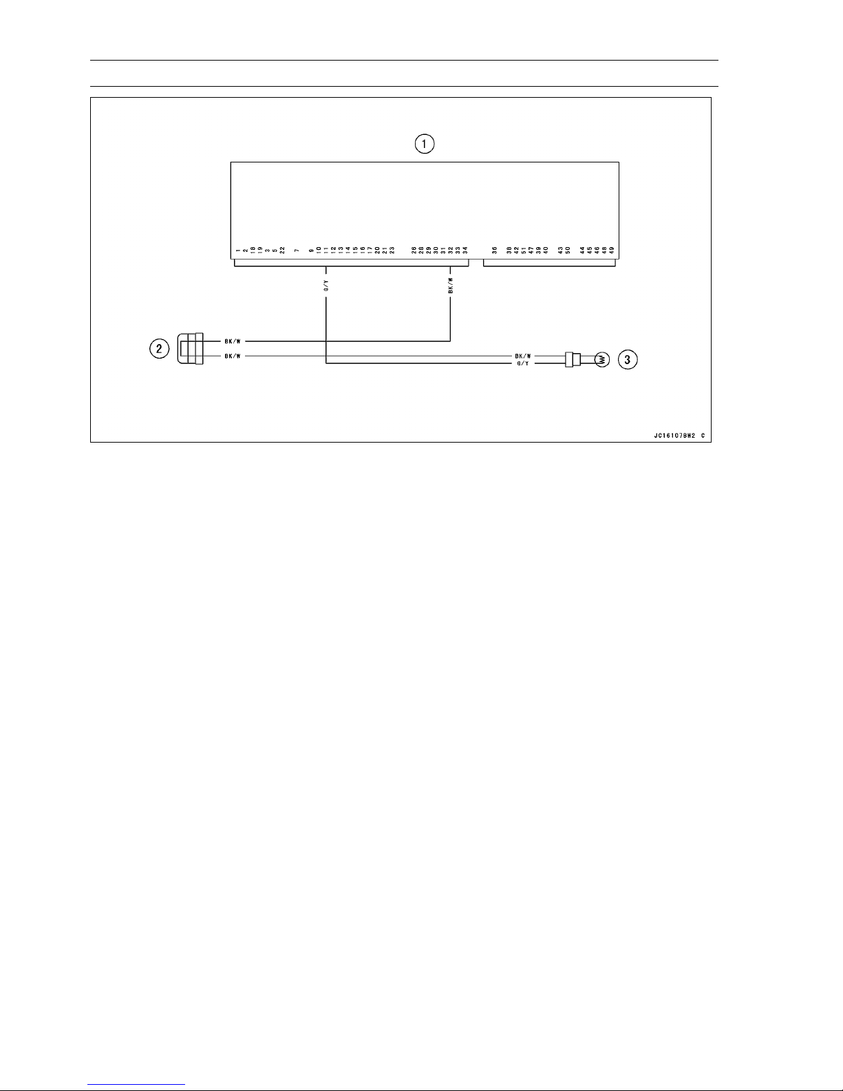
3-40 FUEL SYSTEM (DFI)
Water Temperature Sensor (Service Code/Character-14/AqUt)
1. ECU
2. Joint Connector 5 (Ground - Sensor)
3. Water Temperature Sensor
Sensor Resistance Inspection
Remove the water temperature sensor (see Water Tem-
•
perature Sensor Removal/Installation).
Refer to Electrical System chapter for water temperature
•
sensor inspection.
 Loading...