

Page 1
Page 2

Utility Vehicle
Owner's Manual
ENGLISH
Original instructions
Page 3

Page 4

Quick Reference Guide
GENERAL INFORMATION
This Quick Reference Guide will assist you in
finding the information you're looking for.
BREAK-IN
HOW TO OPERATE
SAFE OPERATION
MAINTENANCE AND ADJUSTMENT
STORAGE
TRANSPORTING AND STORAGE
TROUBLESHOOTING GUIDE
A Table of Contents is included after the Foreword.
Page 5

Page 6
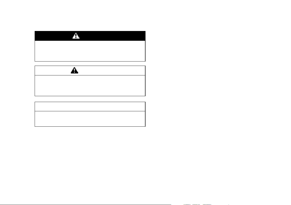
Whenever you see the symbols shown below,
heed their instructions! Always follow safe operating
and maintenance practices.
DANGER
DANGER indicates a hazardous situation
which, if not avoided, will result in death or
serious injury.
WARNING
WARNING indicates a hazardous situation
which, if not avoided, could result in death or
serious injury.
NOTICE
NOTICE is used to address practices not related to personal injury.
NOTE
NOTE indicates information that may help or
○
guide you in the operation or service of the ve-
hicle.
KAF400A .................... MULE 610 4 × 4
KAF400B .................... MULE 600
KAF1000B .................. MULE PRO-DXT
KAF1000E .................. MULE PRO-DX
NOTE
This general OM contains following models.
○
Please refer to where applicable to your MULE.
Page 7

BASIC SAFE DRIVING
Knowing and following these rules for safe operation will increase your satisfaction with your new Kawasaki v ehicle.
Perform the Daily Checks
Refer to the Daily Checks section for a list of items
to check each day before use. Habitual performance of these checks will help to insure safer, more
reliable usage. Be sure that any irregularities found
during these checks are corrected before operating
the vehicle.
Drive Carefully and with Good Judgement
We want you to be satisfied with your new Kawasaki vehicle, so drive carefully, safely, and exercise
good judgement. Practice basic maneuvers so you
can drive confidently and safely.
(KAF1000B/E) Improper use of this vehicle can
be hazardous. Never operate at speeds too fast for
your skills or conditions. Handling characteristics of
this vehicle change depending upon cargo load and
driving modes.
Read the Owner's Manual
Read and understand this Owner's Manual. This
is especially important for inexperienced operators.
Refer to this Owner's Manual if you have any questions.
Off-Highway Use Only
This vehicle is not an all-terrain vehicle; it is designed and equipped to be a multiuse utility vehicle
for off-highway use only. Use of this veh icle on public roads and paved surfaces is hazardous. Do not
operate this vehicle on public roads or paved surfaces.
Occupant Capacity
Make sure operators are 16 years or older with a
valid driver's license.
Each occupant must be able to sit with back
against seat, feet flat on floor, and hands on steering
wheel, handgrip or handhold.
The operator should be tall enough to wear the
seat belt properly and reach all controls.
Passenger(s) should also be tall enough for the
seat belt to fit properly and to be able to brace themselves, as necessary, by placing both feet firmly on
the floor while gripping the handgrip or handhold.
Stay completely inside the vehicle.
Never Drink and Drive
Alcohol and drugs impair your judgement and
slow your reactions. Even drugs prescribed by a
physician can be dangerous. Check with your doctor.
Use Proper Riding Gear
Proper protective gear can reduce the severity of
injury in the event of an accident.
Choose a helmet most appropriate for your use of
this utility vehicle. A helmet can reduce the risk of
Page 8

head injuries. Wear appropriate eye protection and
protective clothing.
Wearing Seat Belts
Both the operator and passenger(s) should always wear their seat belts properly. Seat belts cannot completely protect you in every accident, but in
many cases a seat belt can reduce the risk of serious injury. Also, to avoid injury, do not put any part
of your body outside of the vehicle for any reason.
Close the Doors (KAF1000B/E)
Be sure all doors are securely closed during operation and never remove a door.
The doors prevent branches, gravel, and debris
from getting inside the passenger compartment.
Before Starting the Engine
Three “musts” before starting the engine are:
1. Apply the parking brake,
2. Put the gear shift lever in the “N” (neutral) posi-
tion,
3. Check the throttle pedal for proper operation. It
should return to its rest position when released.
Use the Parking Brake
Always apply the parking brake before getting out
of your vehicle.
Refueling
(KAF400A/B) Before refueling the vehicle, shut
the engine off and make sure the area is well ventilated and free of any source of flame or sparks.
Gasoline is very flammable.
(KAF1000B/E) Before refueling the vehicle, shut
the engine off and make sure the area is well ventilated and free of any source of flame or sparks. Diesel fuel is very flammable.
Tire Air Pressure
Tire inflation and type can affect the vehicle's handling characteristics. Check the tire pressure frequently. Use only the recommended tires for
replacement.
Maximum Seating Capacity
(KAF400A/B, KAF1000E) Do not exceed seating
capacity: 2 occupants.
Occupants shall only ride in designated seating
positions and with maximum 2 persons in the seat.
Do not carry small children on lap.
(KAF1000B) Do not exceed seating capacity: 4
occupants.
Occupants shall only ride in designated seating
positions and with maximum 2 persons in each front
and rear seat.
Do not carry small children on lap.
Obey Local Laws
Know and obey all laws and regulations governing
the use of off-highway vehicles in your area. Respect private property. Always try to preserve nature
and the environment.
Reduce Speed When Carrying Cargo, Passenger(s), and/or Pulling a Trailer
Carrying cargo, passenger(s) and/or pulling a
trailer can make the vehicle difficult to steer and
Page 9

may affect vehicle handling in an unpredictable
manner.
Braking distance is increased when carrying cargo, passenger(s), and/or pulling a trailer. Reduce
speed and allow greater dist ance for braking when
carrying cargo, passenger(s), and/or pulling a trailer.
Use extreme caution when climbing and descending hills, and traversing slopes.
Page 10

FOREWORD
Congratulations on your purchase of a new Kawasaki Mule. It is the result of Kawasaki's engineering exper-
tise and a tradition of manufacturing high-quality consumer products.
Please read this Owner's Manual carefully before starting your new Mule so that you will be thoroughly
familiar with the proper operation of your vehicle's controls, its features, capabilities, and limitations.
To ensure a long, trouble–free life for your Mule, give it the proper care and maintenance described in this
manual.
For those who would like more detailed information on their Mule, a Service Manual is available for purchase
from any authorized Kawasaki Mule dealer. The Service Manual con tains detailed disassembly and maintenance information. Those who plan to do their own work should, of course, be competent mechanics and possess the special tools described in the Service Manual.
Keep this Owner's Manual aboard your Mule at all times so that you can refer to it whenever you need information.
This manual should be considered a permanent part of the Mule and should remain with the Mule when it is
sold.
All rights reserved. No part of this publication may be reproduced without our prior written permission.
This General Owner's Manual offers only the standard descriptions from various models s o some descriptions shown may not apply to your particular model. For detailed information of your Mule (Mule handling, maintenance, service and technical data) refer to the English Owner's Manual. If not available, consult an
authorized Kawasaki dealer.
Page 11

This publication includes the latest information available at the time of printing. However, there may be minor
differences betw een the actual product and illustrations and text in this manual.
All products are subject to change without prior notice or obligation.
KAWASAKI HEAVY INDUSTRIES, LTD.
Motorcycle & Engine Company
© 2016 Kawasaki Heavy Industries, Ltd.
Page 12

Page 13

TABLE OF CONTENTS
SPECIFICATIONS .............................................. 15
DECLARATION OF CONFORMITY ................... 18
SERIAL NUMBER LOCATIONS ........................ 22
LOCATION OF PARTS ....................................... 24
LOCATION OF LABELS .................................... 33
LOADING INFORMATION ................................. 56
GENERAL INFORMATION ................................ 58
Multifunction Meter (KAF1000B/E) .......... ........ 58
Speedometer ................................................. 59
Fuel Level Gauge .......................................... 60
Clock .............................................................. 60
Odometer ...................................................... 61
Trip Meters (Trip Meter A/B) .......................... 61
Hour Meter ..................................................... 62
2WD/4WD Indicator Symbol ......................... 62
Amber Glow Plug Indicator Light ................... 63
Red EPS Warning Indicator Light .................. 64
Red Parking Brake Indicator Light ................ 64
Red Reverse Indicator Light .......................... 64
Green Neutral Indicator Light ........................ 64
Red Seat-Belt Use Reminder ........................ 64
Red Coolant Temperature Warning Indicator
Light ............................................................
Red Oil Pressure Warning Indicator Light ..... 65
Lighting/Electrical Accessory Connector (KA-
F400A/B) .......................................................
Lighting/Electrical Accessory Socket
(KAF1000B/E) ...............................................
Light Switches .................................................. 66
Steering Wheel (KAF1000B/E) ........................ 68
Brake Pedal ...................................................... 69
64
65
66
Converting Rear Seat and Cargo Bed
(KAF1000B) ..................................................
From 4-Persons to 2-Persons Mode ............. 70
From 2-Persons to 4-Persons Mode ............. 73
Cargo Bed ........................................................ 74
Tailgate .......................................................... 74
Cargo Bed ..................................................... 74
Loading Cargo Bed ....................................... 76
Lifting and Lowering the Cargo Bed .............. 77
Choke Knob (KAF400 A/B) ............................... 85
Engine Oil Temperature Warning Light (KA-
F400A) ...........................................................
Fuel Tank (KAF400A/B) ................................... 86
Fuel ................................................................ 87
Fuel (KAF1000B/E) .......................................... 89
Diesel Fuel Requirements ............................. 89
Cold Weather Information ............................. 89
Using Biodiesel Fuel ..................................... 89
Filling the Fuel tank ....................................... 90
Fuel Gauge (KAF400A/B) ................................ 92
Glove Compartment/Tool Kit ............................ 92
Cupholders (KAF1000B/E) .............................. 93
Front Cargo Compartment (KAF400A/B) ........ 94
Front Access Cover (KAF1000B/E) ................. 96
Horn Switch (KAF1000B/E) .............................. 97
Ignition Switch (KAF400A/B) ............................ 98
Main Switch (KAF1000B/E) .............................. 99
Hour Meter (KAF400A/B) .................................100
Shift Lev ers (KAF400A/B) ................................101
Gear Shift Lever ............................................101
2WD-4WD Shift Lever (KAF400A) ................102
70
86
Page 14

Differential Shift Lever ....................................103
Gear Shift Lever (KAF1000B/E) ........................104
Selectable 2WD/4WD Shift Switch
(KAF1000B/E) ................................................
105
Selectable DIFF-LOCK Shift Switch
(KAF1000B/E) ................................................
107
Belt Drive Transmission (KAF1000B/E) ............107
Parking Brake Lever ..........................................108
Parking Brake Warning Light (KAF400A/B) ......109
Doors (KAF1000B/E) ........................................109
Seats ................................................................. 11 0
Seat Belts ..........................................................11 4
Throttle Pedal ....................................................118
Trailer Hitch Bracket .......................................... 118
Winch Installation (KAF400A/B) ........................120
BREAK-IN ............................................................121
HOW TO OPERATE ............................................ 122
Daily Checks .....................................................122
Starting the Engine ............................................125
Throttle-linked choke system .........................125
High-Altitude Injection Control Device ...........127
Cold Weather Starting (KAF1000B/E) ..............128
Jump Starting ....................................................128
Moving Off ......................................................... 132
Braking ..............................................................132
Stopping the Engine ..........................................133
Parking the Mule ...............................................133
Hi-Lo Shifting (KAF400A) ..................................135
Reversing Gears (KAF400A/B) .........................136
Shifting Gears (K AF1000B/E) ...........................136
2WD/4WD Shifting (KAF400A, KAF1000B/E) .. 137
Shifting the Differential ......................................139
When Stuck (KAF1000B/E) ..............................141
SAFE OPERATION .............................................142
Unfamiliar Terrain ..............................................143
Driving in Reverse .............................................143
Driving in “4WD” (KAF400A, KAF1000B/E) ......144
Turning the Vehicle ............................................145
Hills ....................................................................145
Climbing Hills ......................... ............................146
Descending Hills ...............................................147
Traversing Hillsides ...........................................148
Sliding and Skidding ..........................................148
Driving through Water .......................................149
Operator and Passenger Requirements
(KAF1000B/E) ................................................
150
NOISE AND VIBRATION CONTROL INFORMA-
TION ..................................................................
152
Control Information ............................................152
MAINTENANCE AND ADJUSTMENT ................153
Periodic Maintenance Chart ..............................154
Engine Oil ..........................................................161
Front Final Gear Case Oil (KAF400A,
KAF1000B/E) .................................................
169
Transmission Case Oil ......................................174
Cooling Fan (KAF400A/B) .................................180
Cooling System (KAF1000B/E) .........................180
Spark Plug (KAF400A/B) ..................................183
Valve Clearance .................... ............................185
Engine Air Cleaner ............................................185
Spark Arrester ...................................................190
Throttle Pedal ....................................................194
Choke Knob (KAF400 A/B) ................................196
Idle Adjustment (KAF1000B/E) .........................198
Carburetor (KAF400A/B) ...................................198
Fuel System (KAF400A/B) ................................201
Fuel Filter ........................................................202
Fuel Hose (KAF1000B/E) ..................................203
Page 15

Fuel Filter (KAF1000B/E) .................................203
Water Separator (KAF1000B/E) .......................204
Fuel Tank Vent (KAF1000B/E) .........................205
Belt Drive Torque Converter (KAF400A/B) ......205
Belt Drive Torque Converter Air Cleaner (KA-
F400A/B) .......................................................
206
Belt Drive Transmission (CVT) (KAF1000B/E) 209
Brakes ..............................................................210
Brake Pedal ...................................................210
Brake Disc and Brake Pad (KAF1000B/E) ....214
Brake Light Switch ............................................215
Parking Brake Lever (KAF400A/B) ..................217
Parking Brake (KAF1000B/E) ..........................218
Steering Wheel .................................................219
Power Steering System (KAF1000B/E) ........219
Wheels .............................................................220
Rims ..............................................................220
Wheel Nuts ....................................................220
Tires ...............................................................220
Joint Boots ........................................................222
Suspension .......................................................224
Seat Belts .........................................................226
Cargo Bed Latches (KAF1000B/E) ..................227
Headlight Beam ................................................228
Battery ..............................................................229
Fuse ..................................................................242
Breaker (KAF1000B/E) ....................................252
General Lubrication ..........................................253
Cleaning (KAF400A/B) .....................................253
Cleaning (KAF1000B/E) ...................................255
General Precautions .....................................255
Where to be Careful ......................................257
Washing Your Vehicle ...................................257
Bolt and Nut Tightening ....................................258
STORAGE ...........................................................259
TRANSPORTING AND STORAGE ...................261
Transporting the Vehicle (KAF1000B/E) ..........261
Storage (KAF1000B/E) ....................................262
Preparation for Storage .................................262
Engine Care during Long Storage .................263
Removal from Storage ..................................264
Before Starting Engine after Long Storage ...264
TROUBLESHOOTING GUIDE ...........................266
ENVIRONMENTAL PROTECTION ....................268
MAINTENANCE RECORD ................................. 269
Page 16

SPECIFICATIONS
PERFORMANCE
Maximum Torque
Minimum Turning Radius Differential Mode
Seating Capacity (KAF1000B/E)
DIMENSIONS
Overall Length
Overall Width
Overall Height
Wheelbase
Tread: Front
Ground Clearance
Curb Mass
Cargo Bed (L × W × H)
ENGINE
Type
Displacement
Bore × Stroke
Compression Ratio
Starting System
Cylinder Numbering Method (KAF1000B/E)
Firing Order (KAF1000B/E)
SPECIFICATIONS 15
Rear
Page 17

16 SPECIFICATIONS
Carburetor (KAF400A/B)
Ignition System (KAF400A/B)
Ignition Timing (KAF400A/B)
Spark Plug (KAF400A/B)
Injection Pump (KAF1000B/E)
Lubrication System
Engine Oil: Type
Viscosity
Capacity
Coolant Capacity (KAF1000B/E)
DRIVE TRAIN
Driving Type: Primary
Final
Transmission Type
Primary Reduction Ratio
Final Reduction Ratio: Front
Rear
Overall Drive Ratio: Forward
Reverse
Transmission Gear Ratio: Forward
Reverse
Front Final Gear Case Oil
Front Final Gear Case Oil Capacity
Transmission Case Oil
Page 18

Transmission Case Oil Capacity
FRAME
Type
Steering (KAF1000B/E)
Caster
Trail (KAF400A/B)
Tire Size: Front
Rear
Rim Size:
Front
Rear
Fuel Tank Capacity
ELECTRICAL EQUIPMENT
Battery
Headlight:
High Beam
Low Beam
Brake/Tail Light
Reverse Light
LOAD CAPACITY
Maximum Vehicle Load (Including occupants, cargo and
accessories)
Maximum Cargo Bed Load
SPECIFICATIONS 17
Specifications are subject to change without notice.
Page 19
18 DECLARATION OF CONFORMITY
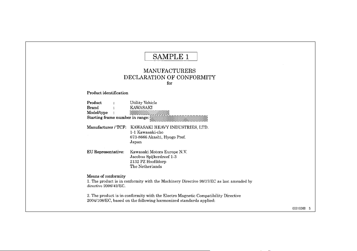
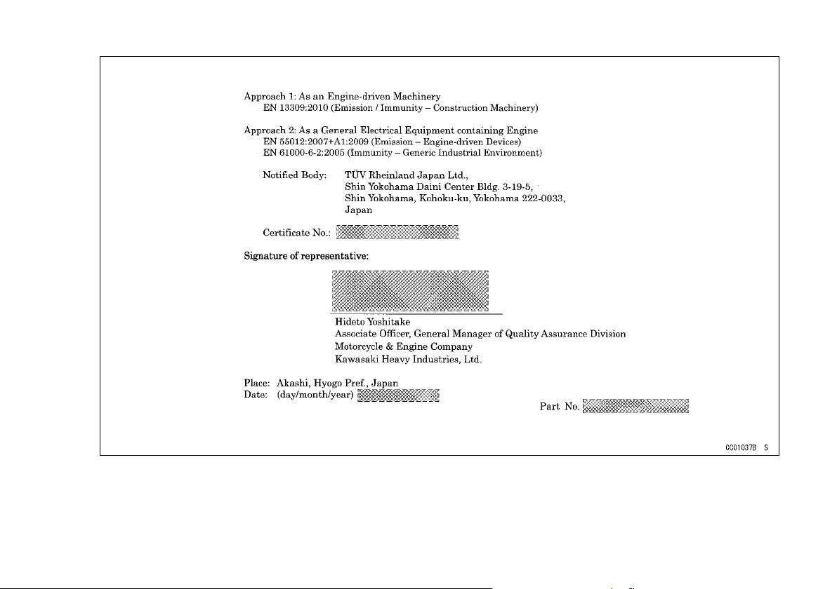
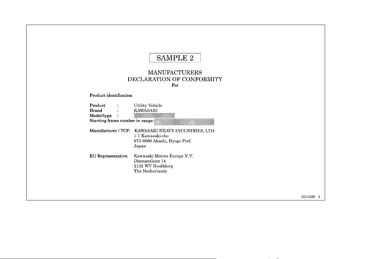
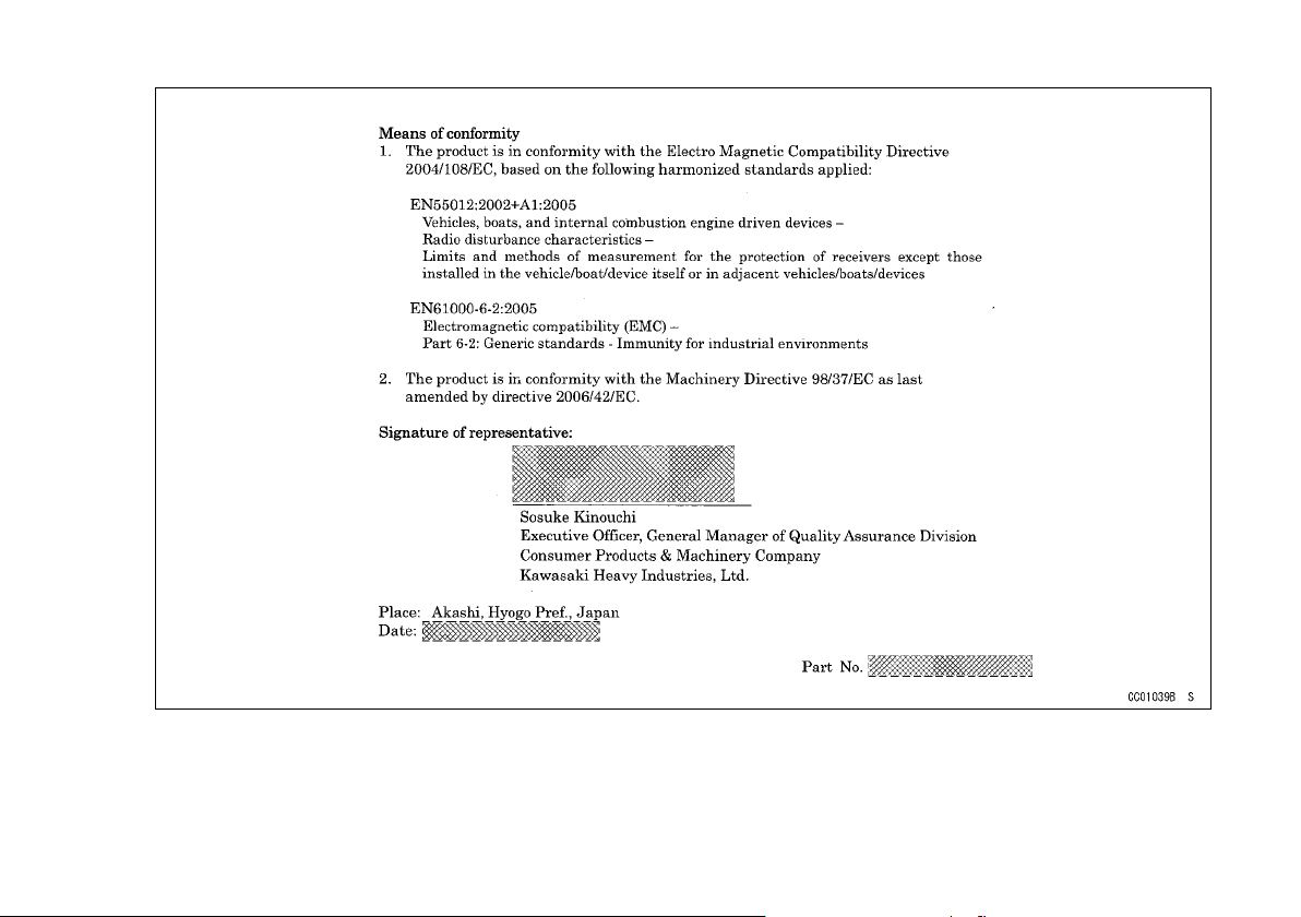
DECLARATION OF CONFORMITY
Page 20
DECLARATION OF CONFORMITY 19
Page 21
20 DECLARATION OF CONFORMITY
Page 22
DECLARATION OF CONFORMITY 21
Page 23
22 SERIAL NUMBER LOCATIONS
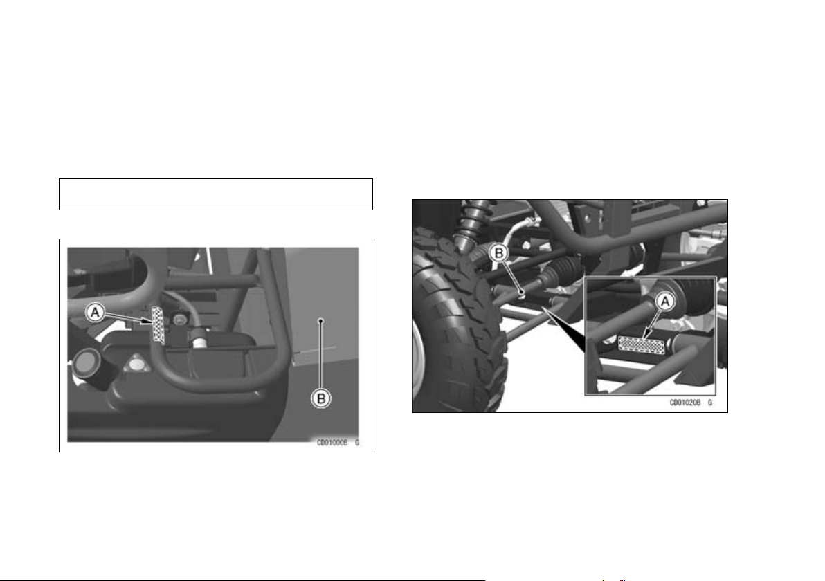
SERIAL NUMBER LOCATIONS
The engine and frame serial numbers are used to register the vehicle. They are the only means of identifying
your particular machine from others of the same model type. These serial numbers may be needed by your
dealer when ordering parts. In the event of theft, the investigating authorities will require both numbers as well
as the model type and any peculiar features of your machine that can help them identify it.
Frame No.
(KAF400A/B)
A. Frame Number
B. Seat (Raised Position)
(KAF1000B/E)
A. Frame Number
B. Right Front Axle
Page 24
SERIAL NUMBER LOCATIONS 23
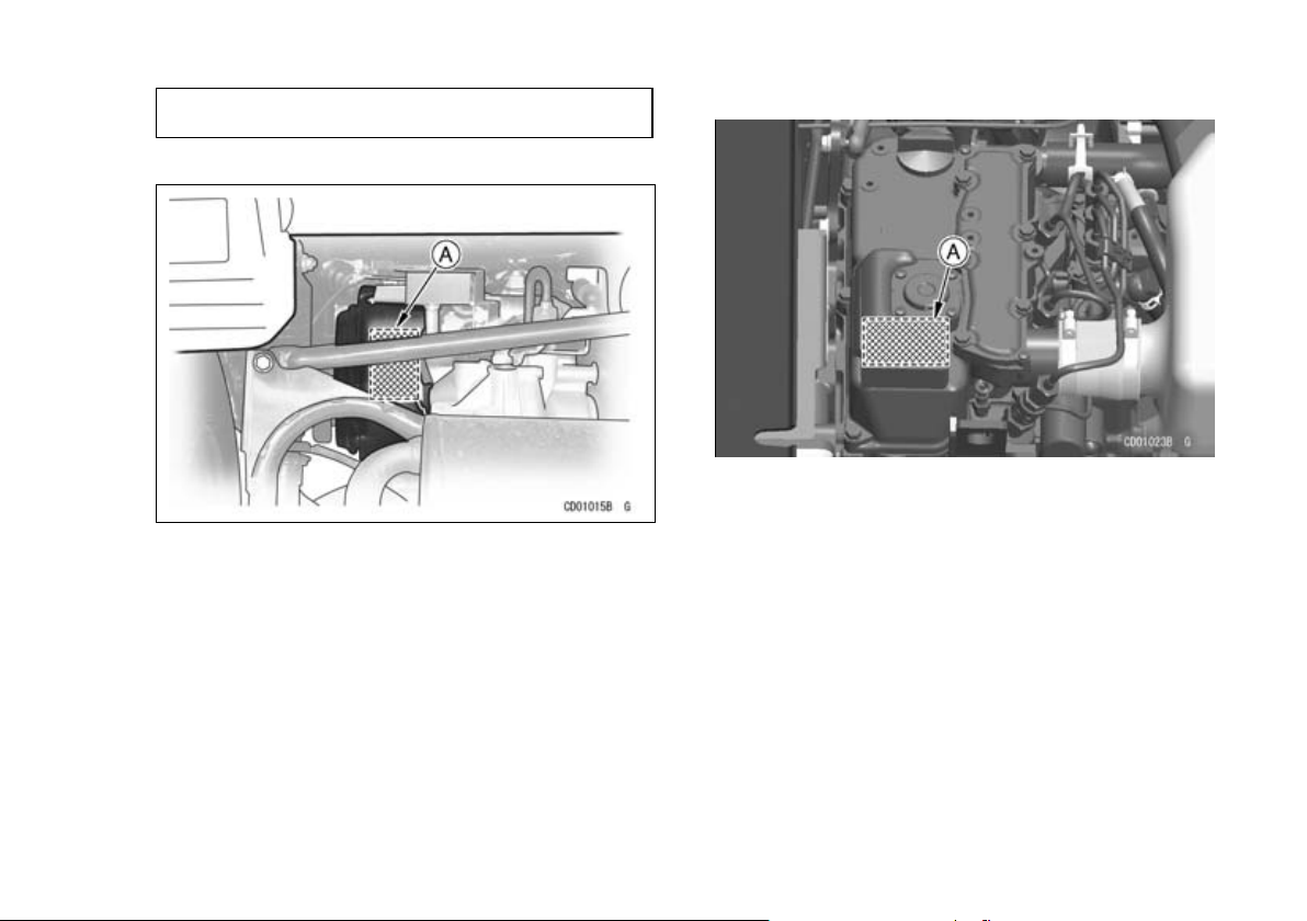
Engine No.
(KAF400A/B)
A. Engine Number
(KAF1000B/E)
A. Engine Number
Page 25
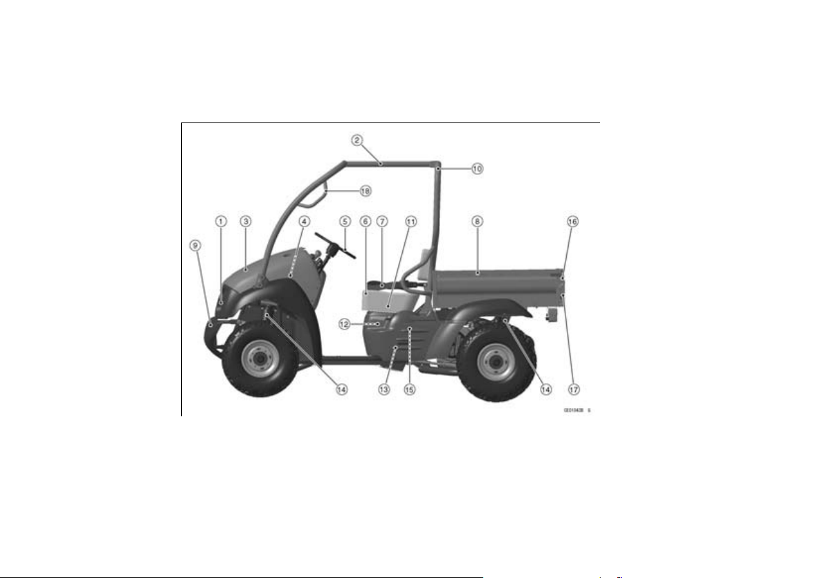
24 LOCATION OF PARTS
(KAF400A/B)
LOCATION OF PARTS
1. Headlights
2. ROPS (Roll Over Protective
Structure)
3. Front Cargo Hood
4. Front Cargo Compartment
5. Steering Wheel
6. Seat
7. Seat Belts
8. Cargo Bed
9. Grille (Front Bumper)
10. Air Cleaner Intake
11. Parking Brake
12. Air Cleaner (Carburetor)
13. Battery
14. Suspensions
15. Carburetor
16. Latch
17. Tail Gate
18. Handgrip
Page 26
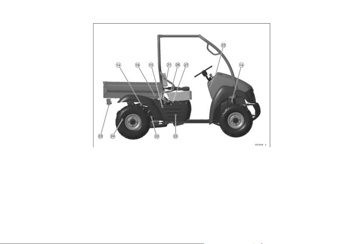
LOCATION OF PARTS 25
18. Handgrip
19. Air Cleaner (Belt Drive Torque
Converter)
20. Belt Drive Torque Converter
21. Latch
22. Dashboard
23. Brake/Tail Light
24. Muffler
25. Fuel Tank
26. Fuel Tank Cap
27. Fuel Gauge
Page 27
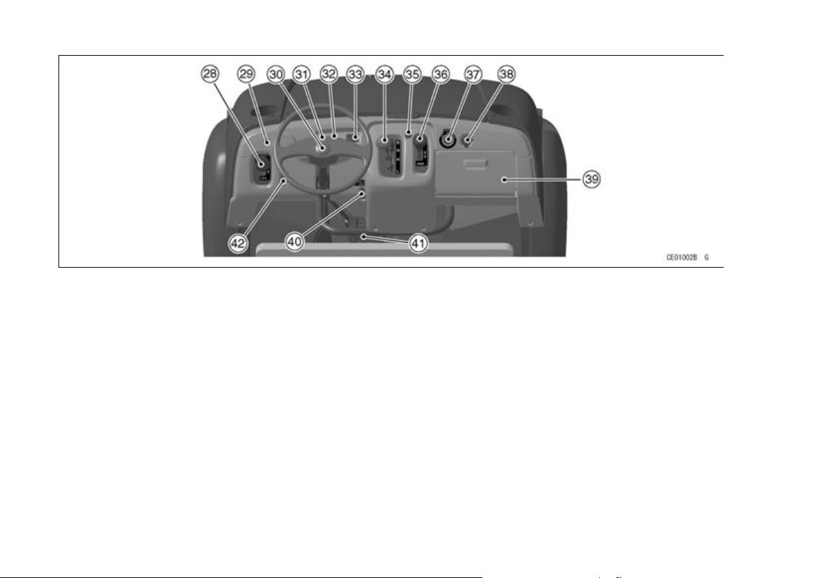
26 LOCATION OF PARTS
28. Differential Shift Lever
29. Choke Knob
30. Horn Button
31. Engine Oil Temperature
Warning Light
32. Parking Brake Warning Light
33. Hour Meter
34. Gear Shift Lever
35. Front Cargo Latch
36. 2WD-4WD Shift Lever(KAF400A)
37. Ignition Switch
38. Accessory Connector
39. Glove Compartment
40. Brake Fluid Level
41. Brake Light Switch
42. Light Switch
Page 28
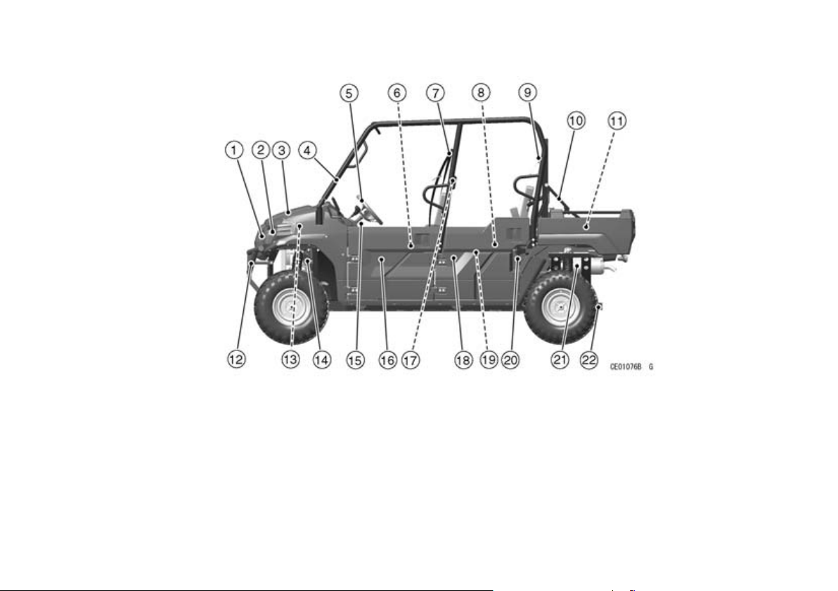
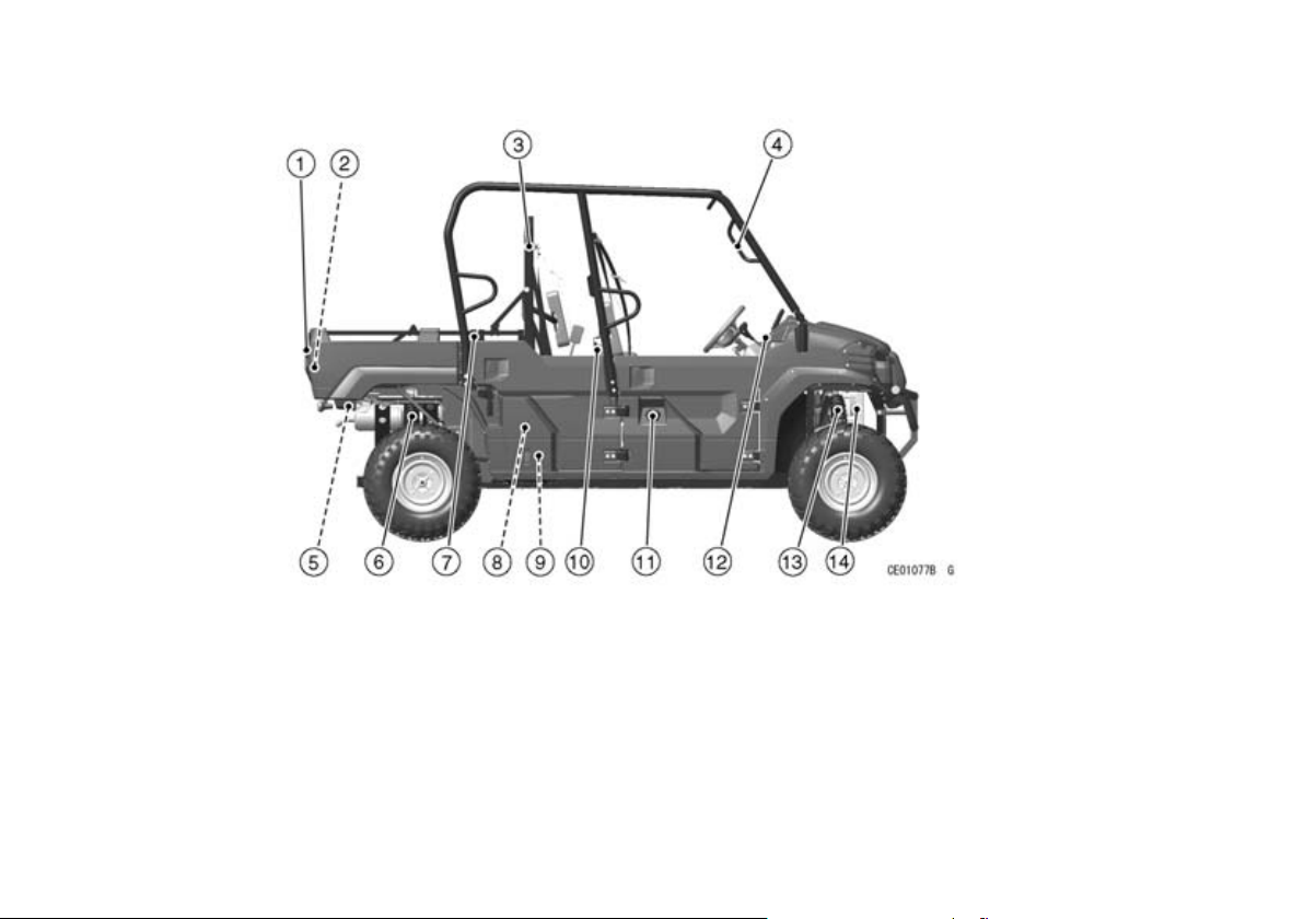
(KAF1000B, 4-Persons Mode)
LOCATION OF PARTS 27
1. LED Sub Headlights
2. Headlights
3. Front Access Cover
4. ROPS (Roll Over Protective
Structure)
5. Steering Wheel
6. Front Seat
7. Front Seat Belts
8. Rear Seat
9. Rear Seat Belts
10. Screen Lock Arm
11. Cargo Bed
12. Front Guard
13. Coolant Reserve Tank
14. Brake Fluid Reservoir
15. Steering Wheel Tilt Lock Lever
16. Front Door
17. Handhold for Rear Seat Passengers
18. Rear Door
19. Cargo Bed Handgrip
20. Cargo Bed Latch
21. Muffler (Spark Arrester)
22. Trailer Hitch Bracket
Page 29
28 LOCATION OF PARTS
(KAF1000B, 2-Persons Mode)
1. Tailgate Latch Handle
2. Tailgate
3. Screen
4. Handgrip for Front Right Seat
Passenger
5. Tail/Brake Light
6. Rear Shock Absorber
7. Cargo Bed Side Plate
8. Air Cleaner
9. Battery
10. Rear Seat (Folded Position)
11. Fuel Tank Cap
12. Dashboard
13. Front Shock Absorber
14. Radiator
Page 30
LOCATION OF PARTS 29
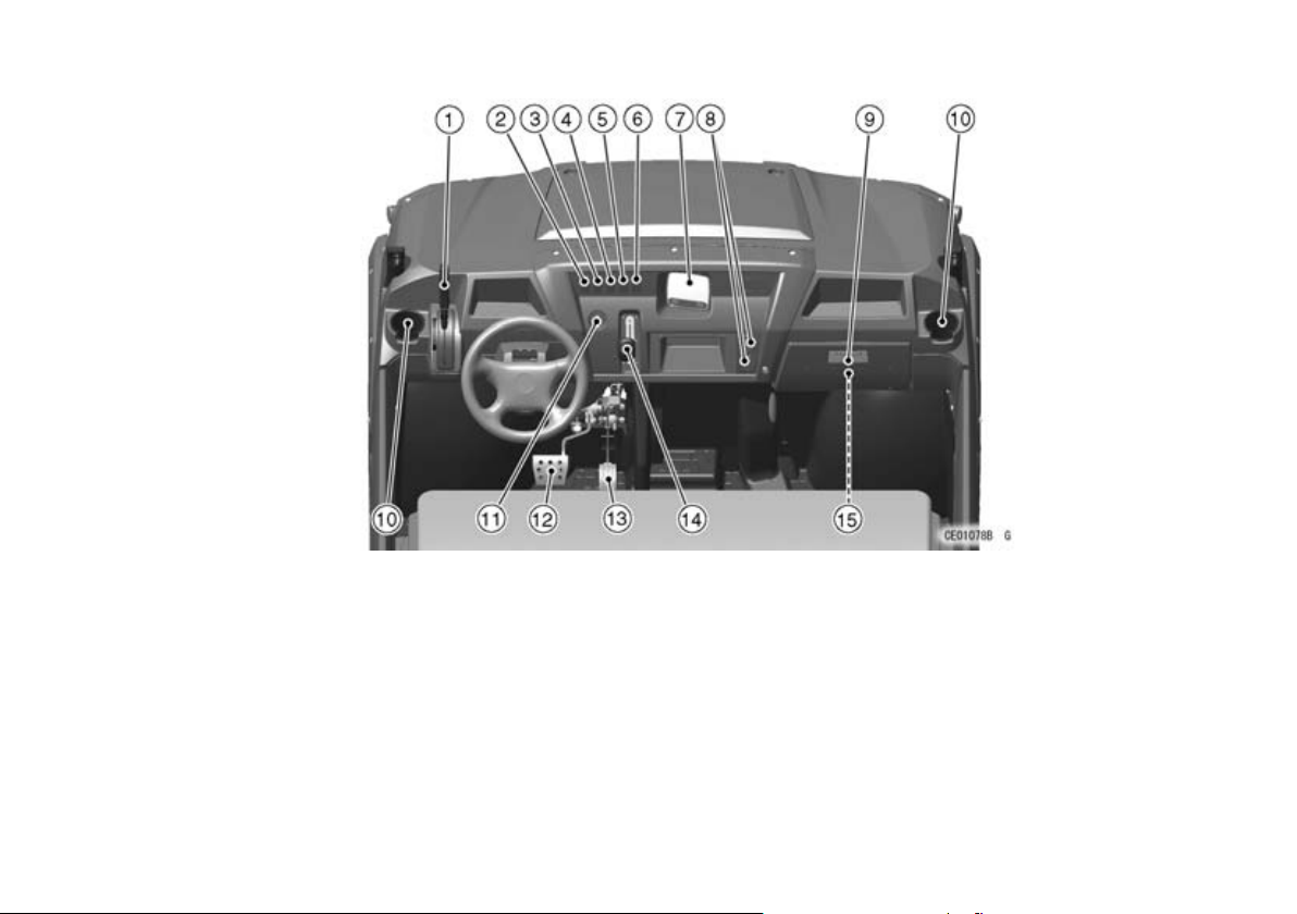
1. Parking Brake Lever
2. Horn Switch
3. Selectable DIFF-LOCK Shift
Switch
4. Selectable 2WD/4WD Shift
Switch
5. Headlight Switch
6. LED Sub Headlight Switch
7. Multifunction Meter
8. Power Outlet Sockets
9. Glove Compartment
10. Cupholders
11. Main Switch
12. Brake Pedal
13. Throttle Pedal
14. Gear Shift Lever
15. Tool Kit
Page 31
30 LOCATION OF PARTS
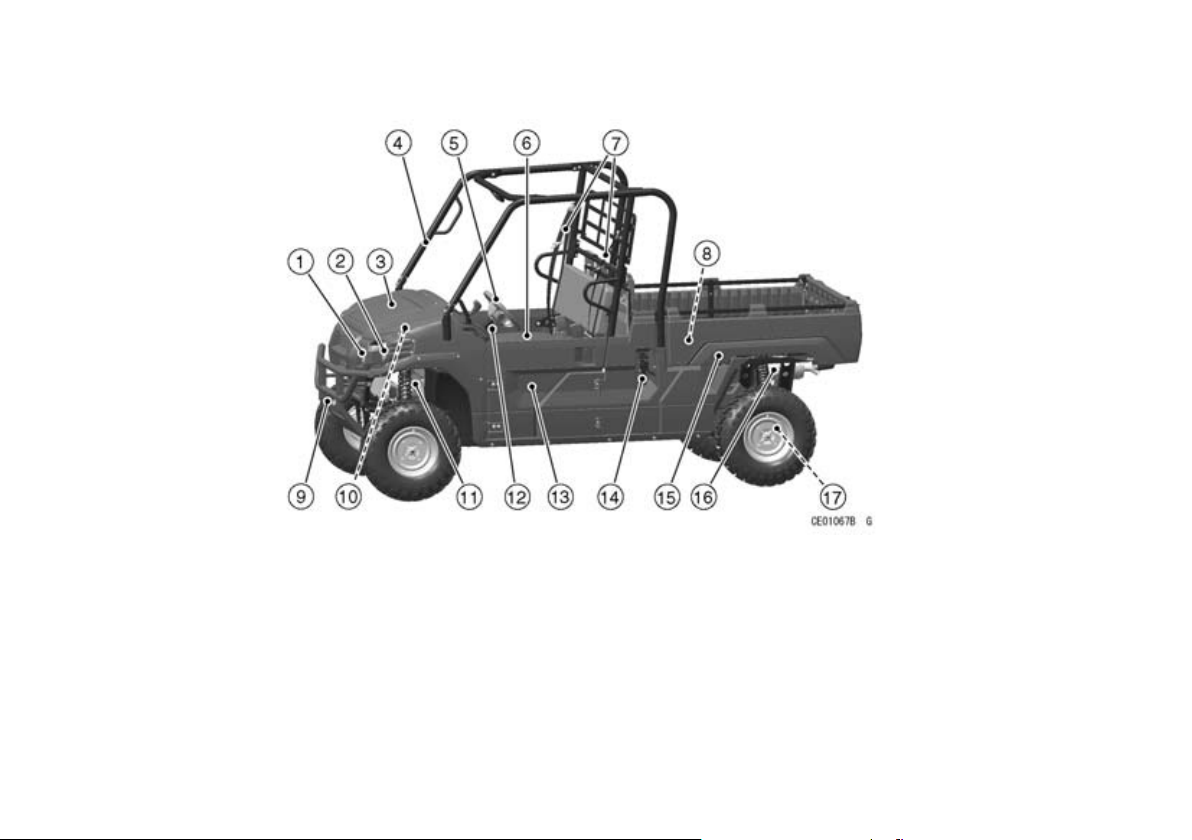
(KAF1000E)
1. LED Sub Headlights
2. Headlights
3. Front Access Cover
4. ROPS (Roll Over Protective
Structure)
5. Steering Wheel
6. Seat
7. Seat Belts
8. Cargo Bed
9. Front Guard
10. Coolant Reserve Tank
11. Brake Fluid Reservoir
12. Steering Wheel Tilt Lock Lever
13. Door
14. Cargo Bed Latch
15. Cargo Bed Handgrip
16. Muffler (Spark Arrester)
17. Trailer Hitch Bracket
Page 32
LOCATION OF PARTS 31
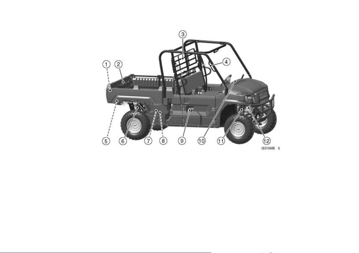
1. Tailgate Latch Handle
2. Tailgate
3. Screen
4. Handgrip for Right Seat Passenger
5. Tail/Brake Light
6. Rear Shock Absorber
7. Air Cleaner
8. Battery
9. Fuel Tank Cap
10. Dashboard
11. Front Shock Absorber
12. Radiator
Page 33
32 LOCATION OF PARTS
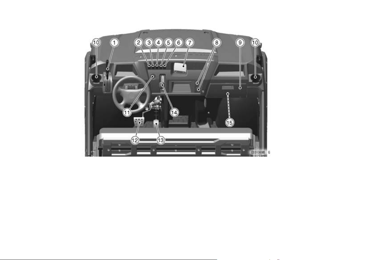
1. Parking Brake Lever
2. Horn Switch
3. Selectable DIFF-LOCK Shift
Switch
4. Selectable 2WD/4WD Shift
Switch
5. Headlight Switch
6. LED Sub Headlight Switch
7. Multifunction Meter
8. Power Outlet Sockets
9. Glove Compartment
10. Cupholders
11. Main Switch
12. Brake Pedal
13. Throttle Pedal
14. Gear Shift Lever
15. Tool Kit
Page 34
LOCATION OF LABELS
LOCATION OF LABELS 33
Some labels are not applicable to all models, and
their location may also vary depending on models.
Please note that illustrations of models and labels
used here are for representation purposes only.
For information specific to your model, refer to the
English Owner's Manual or contact an authorized
Kawasaki dealer or the distributor.
NOTE
Labels and their locations listed hereafter are for
○
KAF1000B for example use only. See your own
OM in English for relevant information.
All warning labels which are on your vehicle are
repeated here. Read labels on your vehicle and
understand them thoroughly. They contain information which is important for your safety and the safety
of anyone else who may operate your vehicle.
Therefore, it is very important that all warning labels
be on your vehicle in the locations shown. If any label is missing, damaged, or worn, get a replacement
from your Kawasaki dealer and install it in the correct position.
NOTE
The sample warning labels in this section have
○
part numbers to help you and your dealer obtain
the correct replacem ent.
Refer to the actual vehicle label for model specific
○
data grayed out in the illustration.
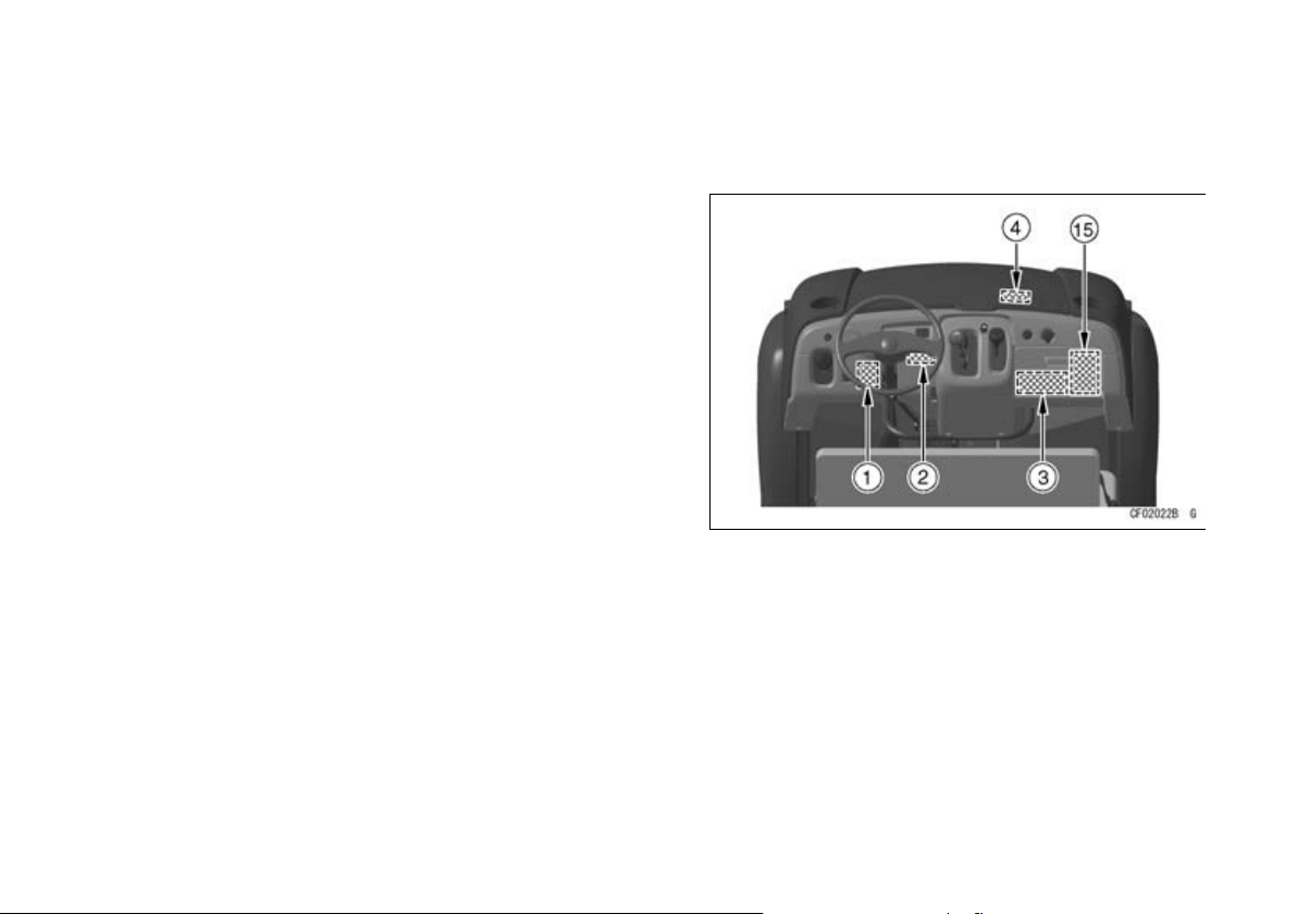
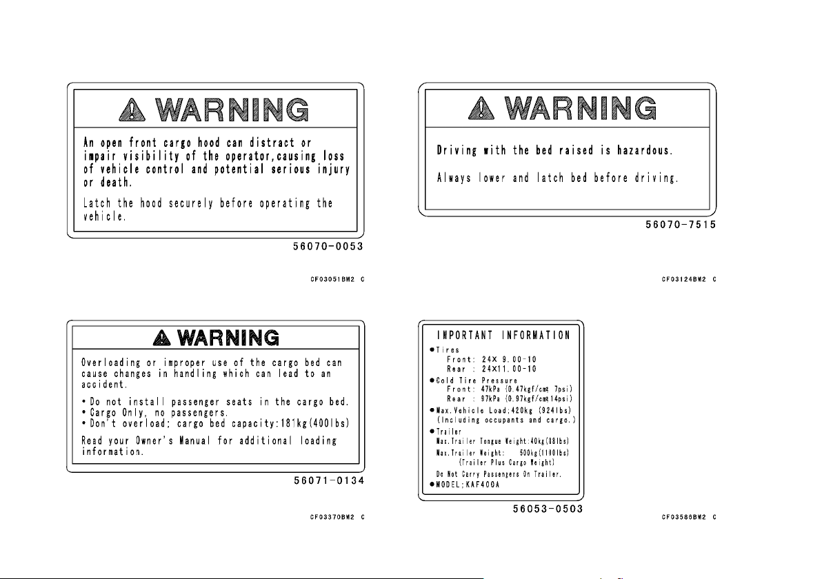
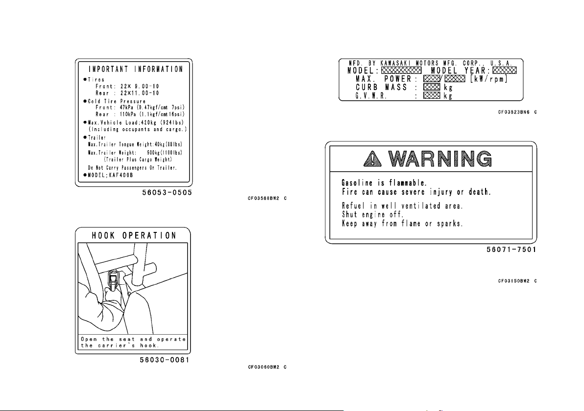
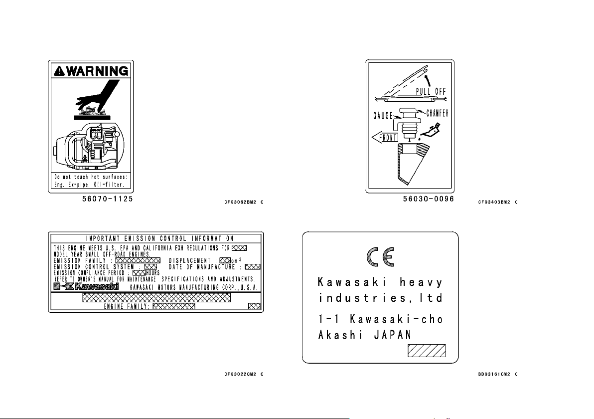
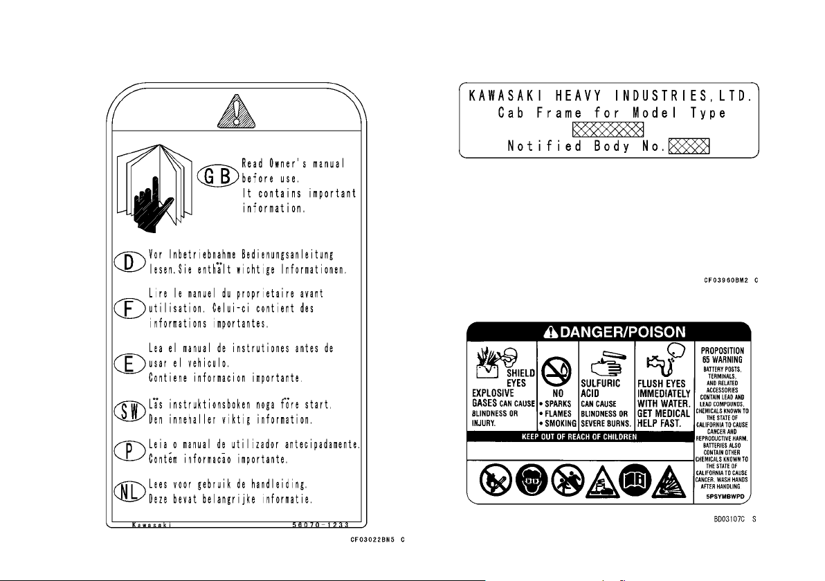
(KAF400A/B)
1. Warning (Off-Highway Utility Vehicle)
2. Notice (Shifting)
3. Warning (General)
4. Warning (Front Cargo Hood)
15. Warning (Read Owner's Manual)
Page 35
34 LOCATION OF LABELS
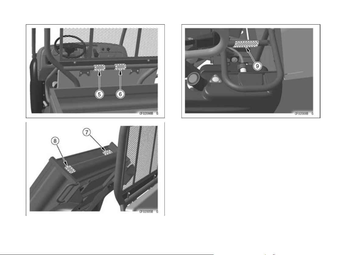
5. Warning (Passengers in Cargo Bed)
6. Warning (Cargo Bed)
7. Important Information (Tires/Max. Load)
8. Carrier Hook Operation
9. Specification
Page 36
LOCATION OF LABELS 35
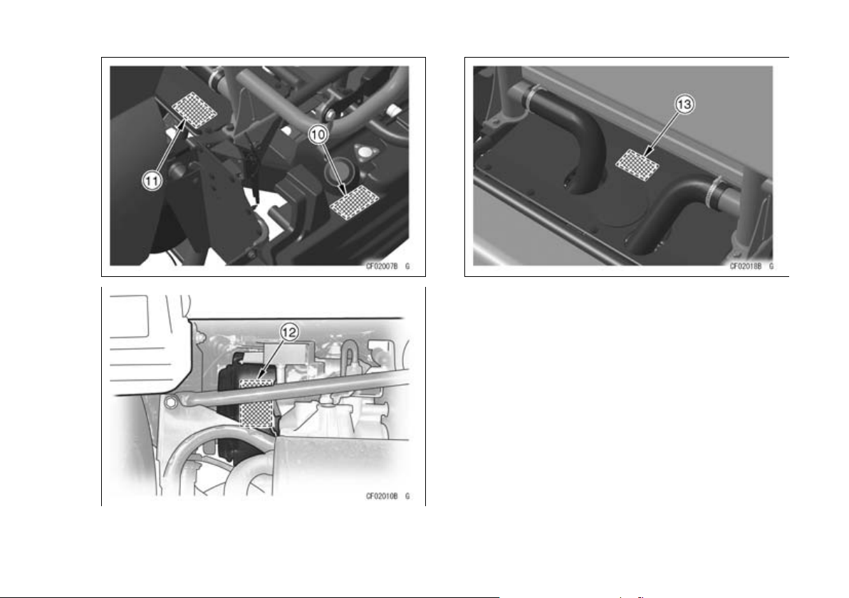
10. Warning (Refueling)
11. Warning (Hot Surface)
12. Important Emission Control Information
13. Engine Oil Information
Page 37
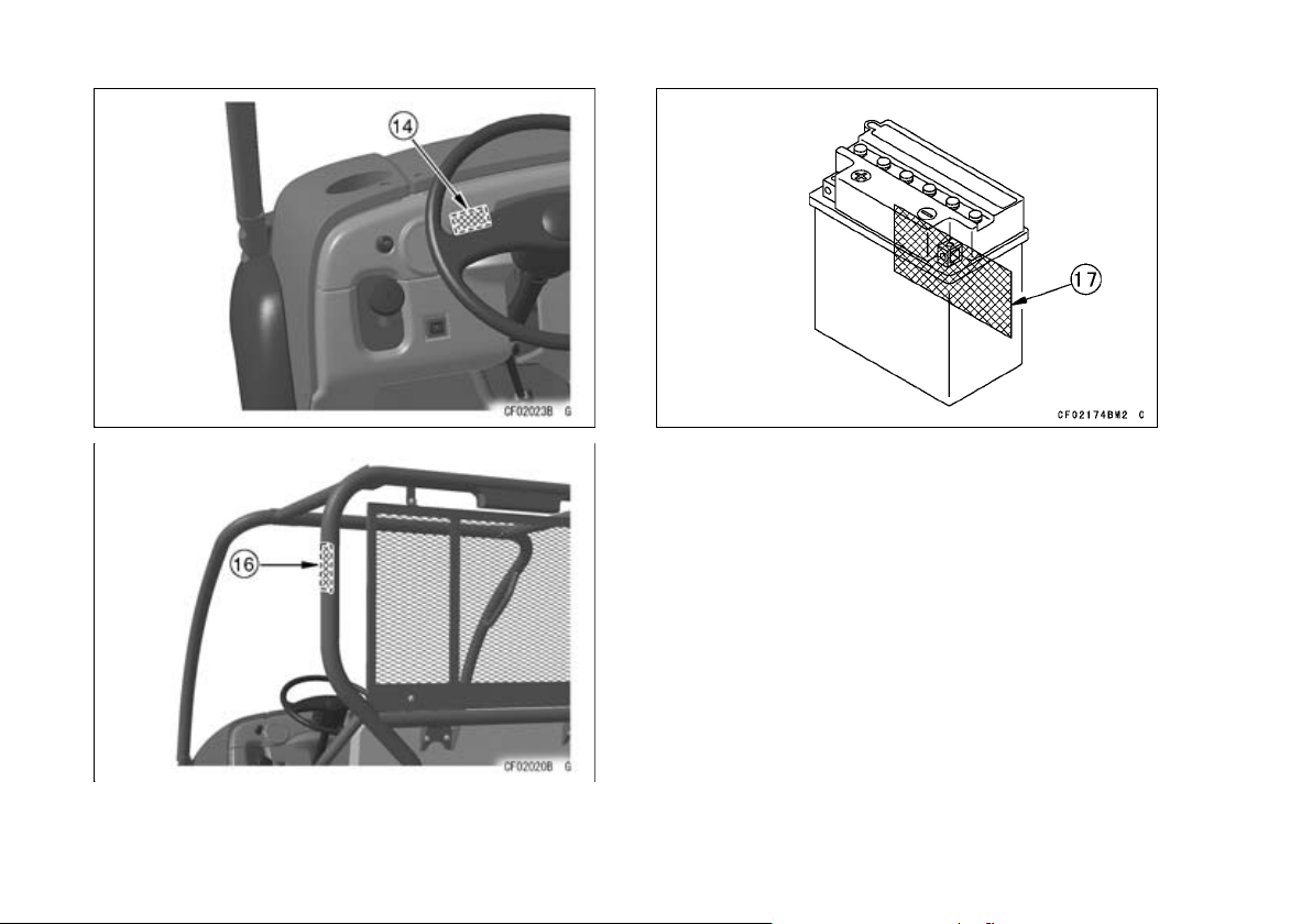
36 LOCATION OF LABELS
14. CE Mark
16. Certification (ROPS)
17. Battery Danger/Poison (On the backside)
Page 38
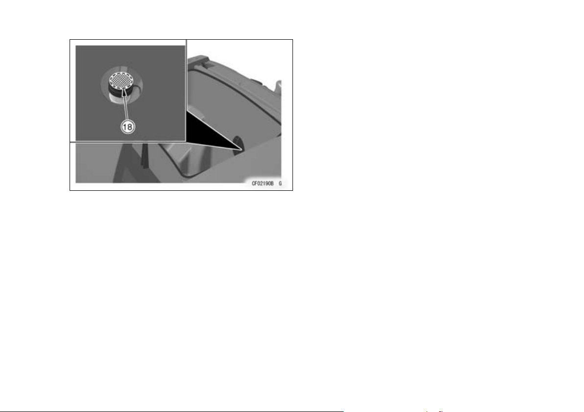
18. Brake Fluid
LOCATION OF LABELS 37
Page 39
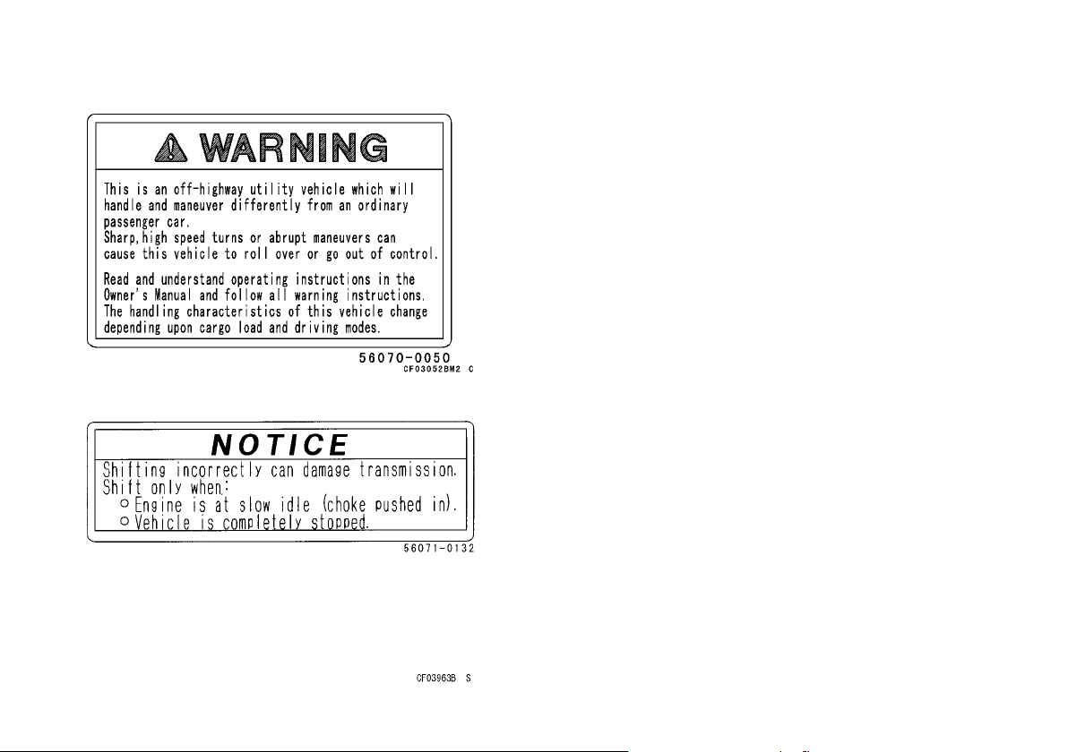
38 LOCATION OF LABELS
(1)
(2)
Page 40
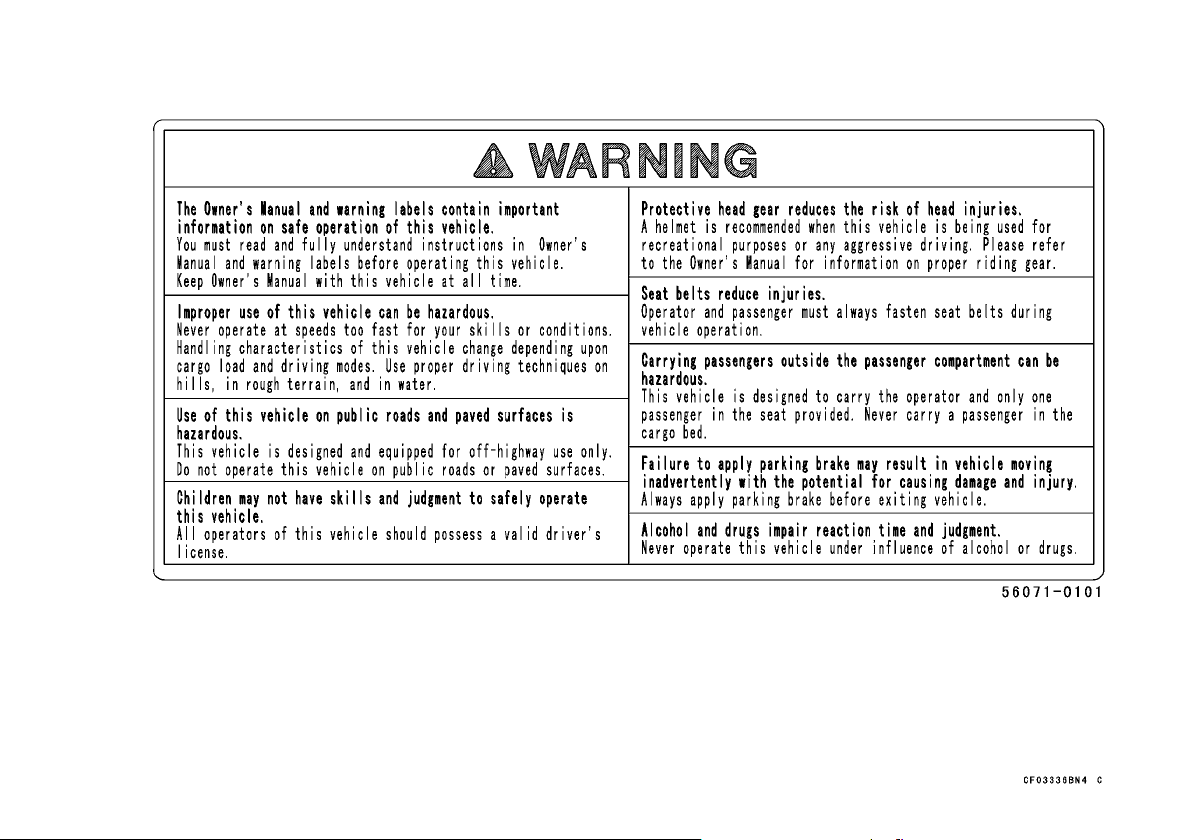
(3)
LOCATION OF LABELS 39
Page 41
40 LOCATION OF LABELS
(4)
(5)
(6)
(7) (KAF400A)
Page 42
LOCATION OF LABELS 41
(7) (KAF400B)
(8)
(9)
(10)
Page 43
42 LOCATION OF LABELS
(11)
(12)
(13)
(14)
Page 44
(15) (16)
(17)
LOCATION OF LABELS 43
Page 45

44 LOCATION OF LABELS
(18)
Page 46
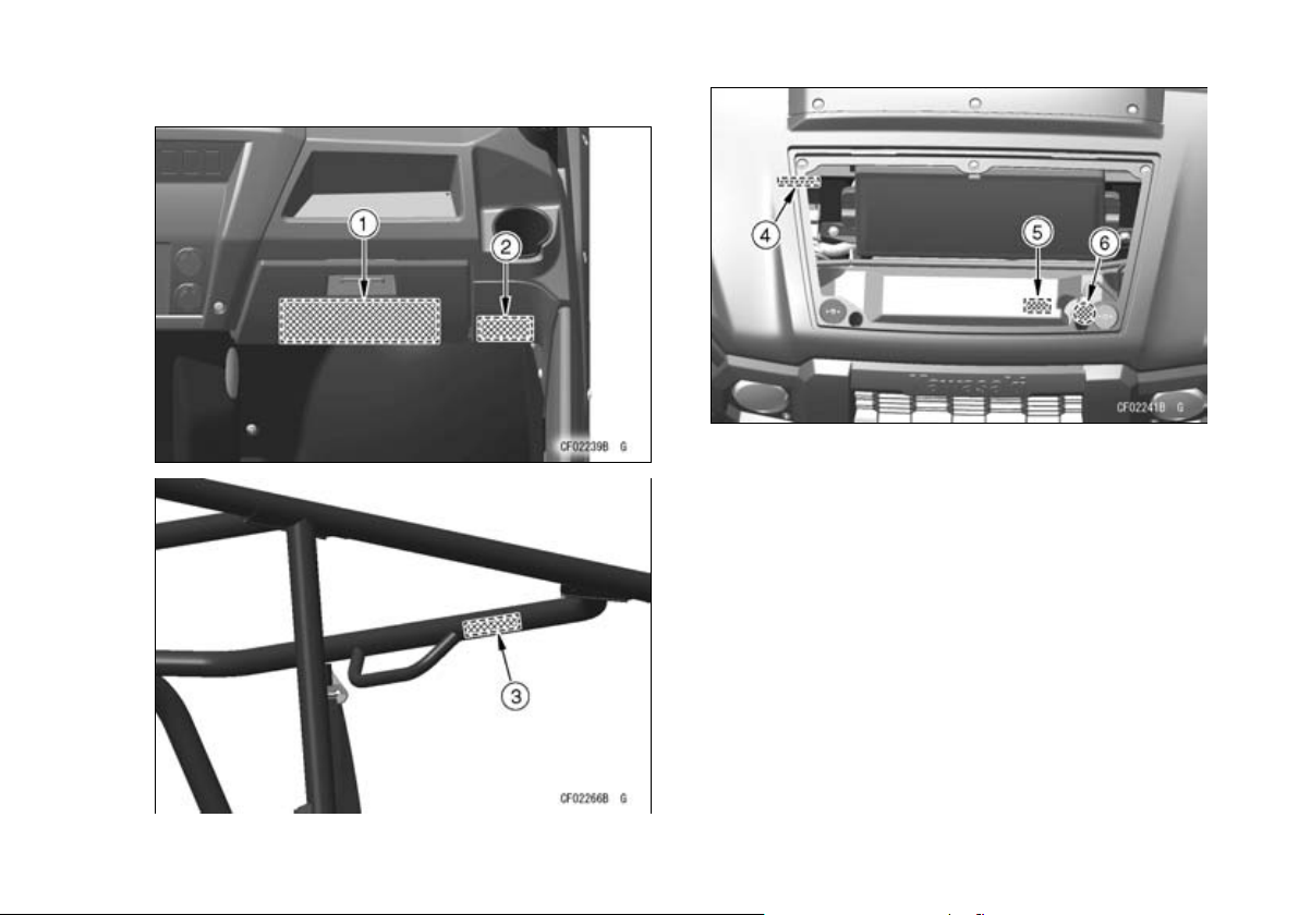
(KAF1000B)
LOCATION OF LABELS 45
1. Warning (General)
2. CE Mark
3. Specification (ROPS)
4. Specification (Model)
5. Danger (Radiator Cap)
6. Danger (Radiator Cap)
Page 47
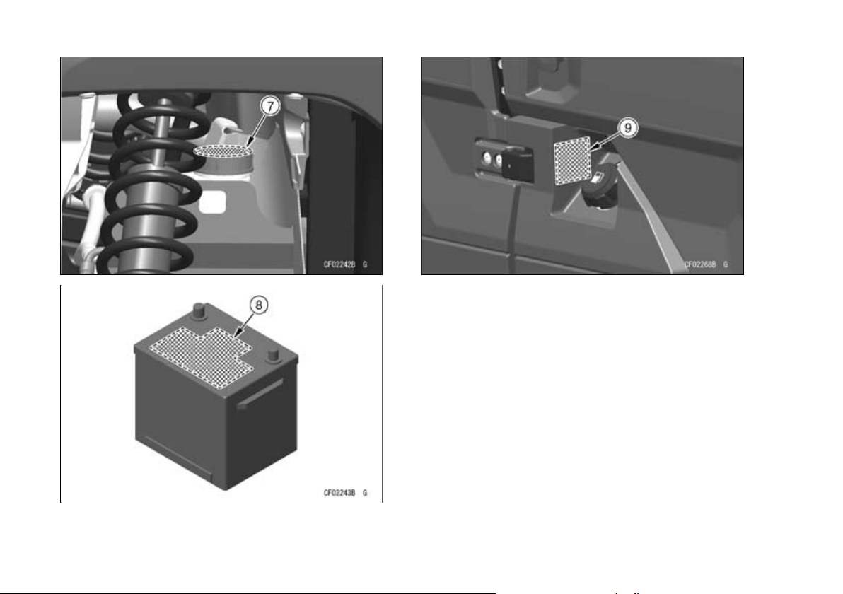
46 LOCATION OF LABELS
7. Warning (Brake Fluid)
8. Danger/Poison (Battery)
9. Warning (Refueling)
Page 48
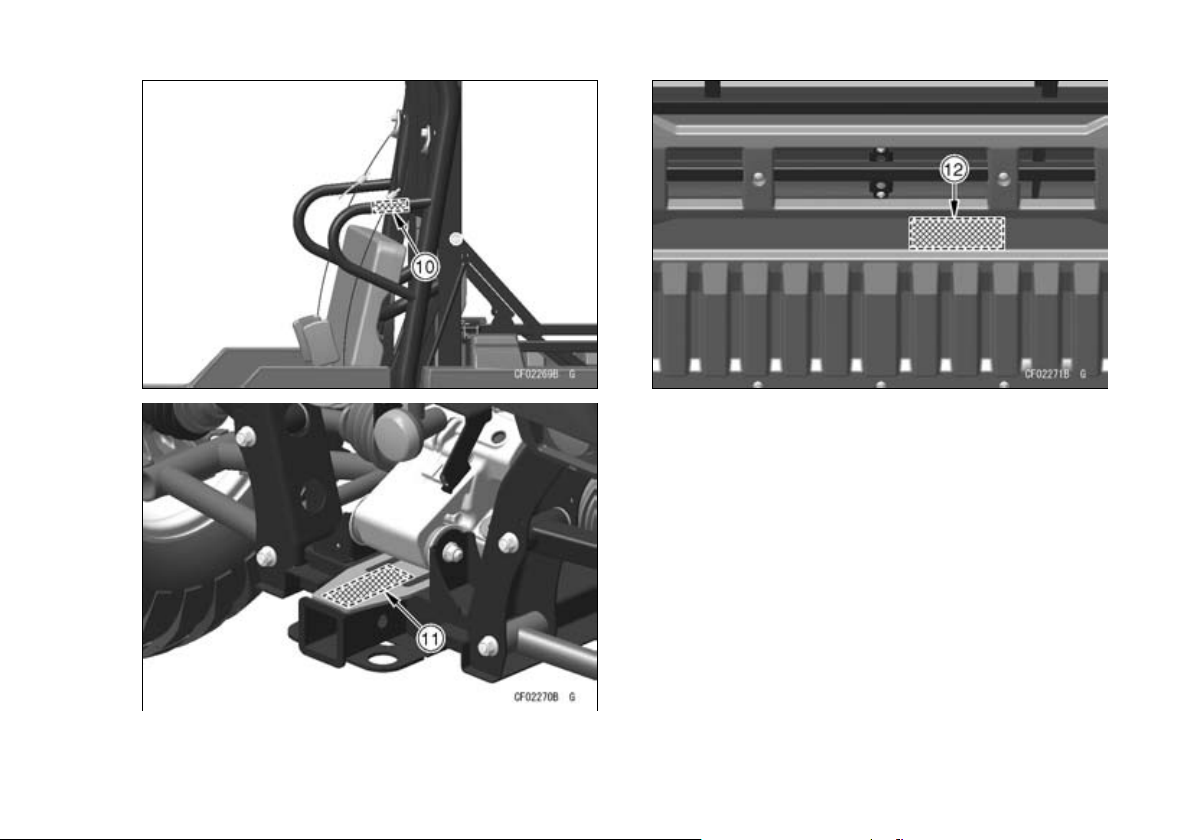
LOCATION OF LABELS 47
10. Warning (Cargo Bed Lifting: both sides)
11. Warning (Trailer Towing)
12. Warning (Cargo Bed Loading)
Page 49
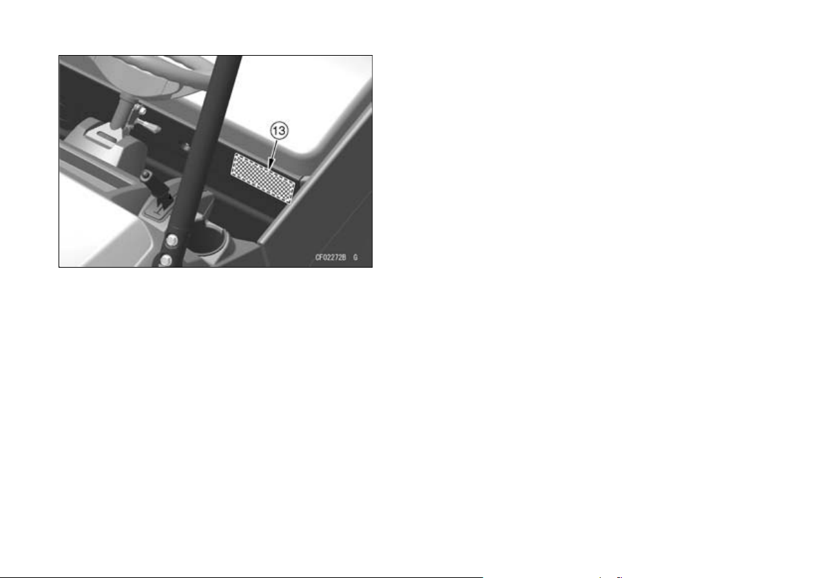
48 LOCATION OF LABELS
13. Important Information (Tires/Max. Load)
Page 50
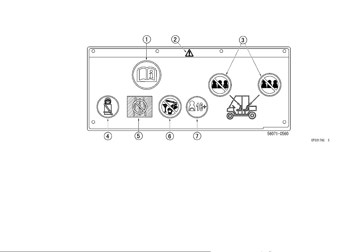
(1)
1. Read Owner’s Manual
2. Safety alert symbol
3. Maximum seating capacity: 2 persons in each
seat, see “BASIC SAFE DRIVING” section
4. Fasten seat belts. Wear an approved helmet and
protective gear, see “BASIC SAFE DRIVING”
section
5. Never use on public roads, see “BASIC SAFE
DRIVING” section
6. Never use with drugs or alcohol, see “BASIC
SAFE DRIVING” section
7. Make sure operators are 16 years or older with a
valid driver’s license, see “BASIC SAFE DRIVING” section
LOCATION OF LABELS 49
Page 51
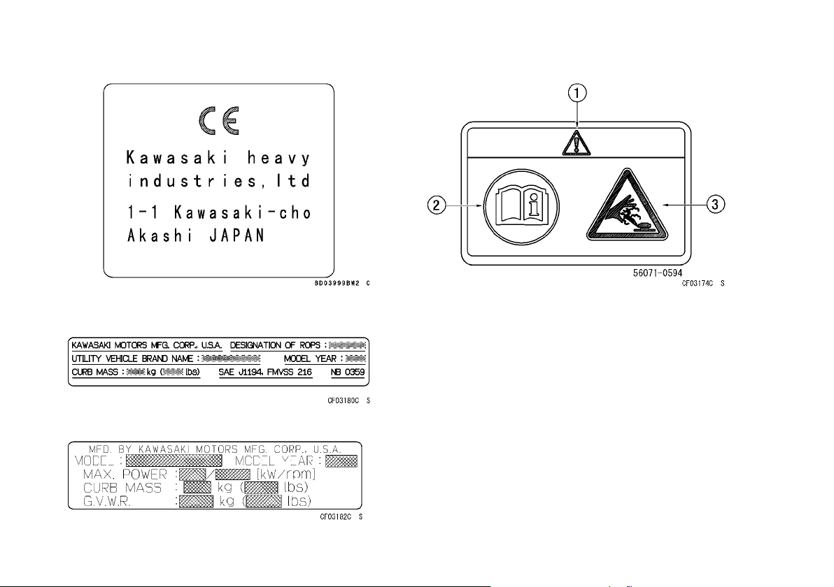
50 LOCATION OF LABELS
(2)
(3)
(4)
(5)
1. Safety alert symbol
2. Read Owner’s Manual
3. Hot liquid. Never open when engine is hot
Page 52
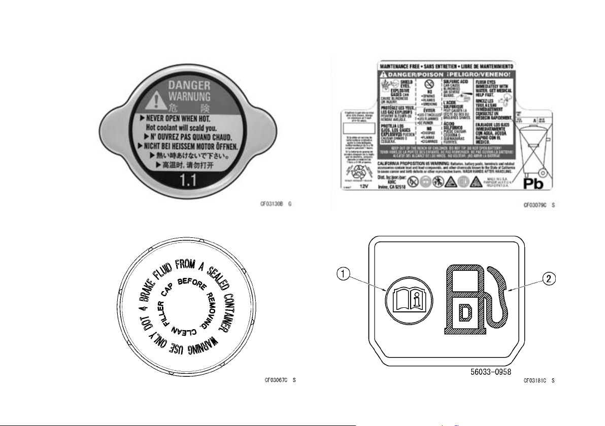
LOCATION OF LABELS 51
(6)
(7)
(8)
(9)
1. Read Owner’s Manual
2. Use diesel fuel only
Page 53
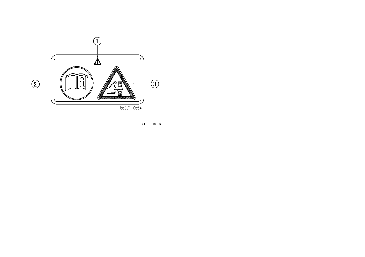
52 LOCATION OF LABELS
(10)
1. Safety alert symbol
2. Read Owner’s Manual
3. Hand crush
Page 54
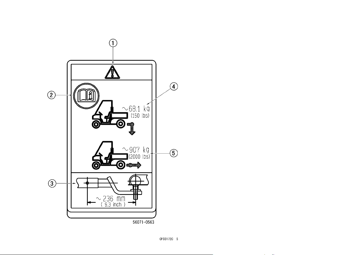
LOCATION OF LABELS 53
(11)
1. Safety alert symbol
2. Read Owner’s Manual
3. Maximum arm length
4. Vertical force limitation
5. Horizontal force limitation
Page 55
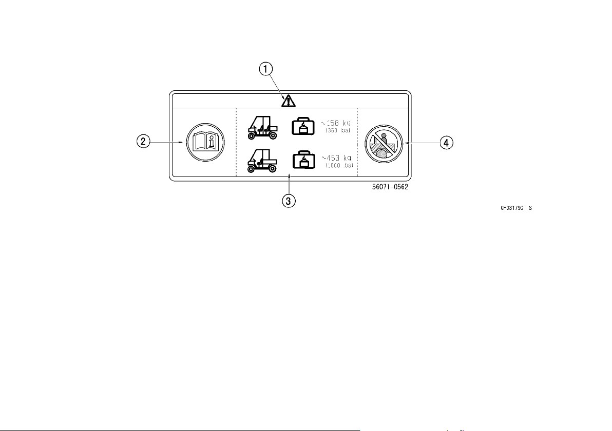
54 LOCATION OF LABELS
(12)
1. Safety alert symbol
2. Read Owner’s Manual
3. Maximum cargo bed load
4. Never carry passengers in cargo bed
Page 56
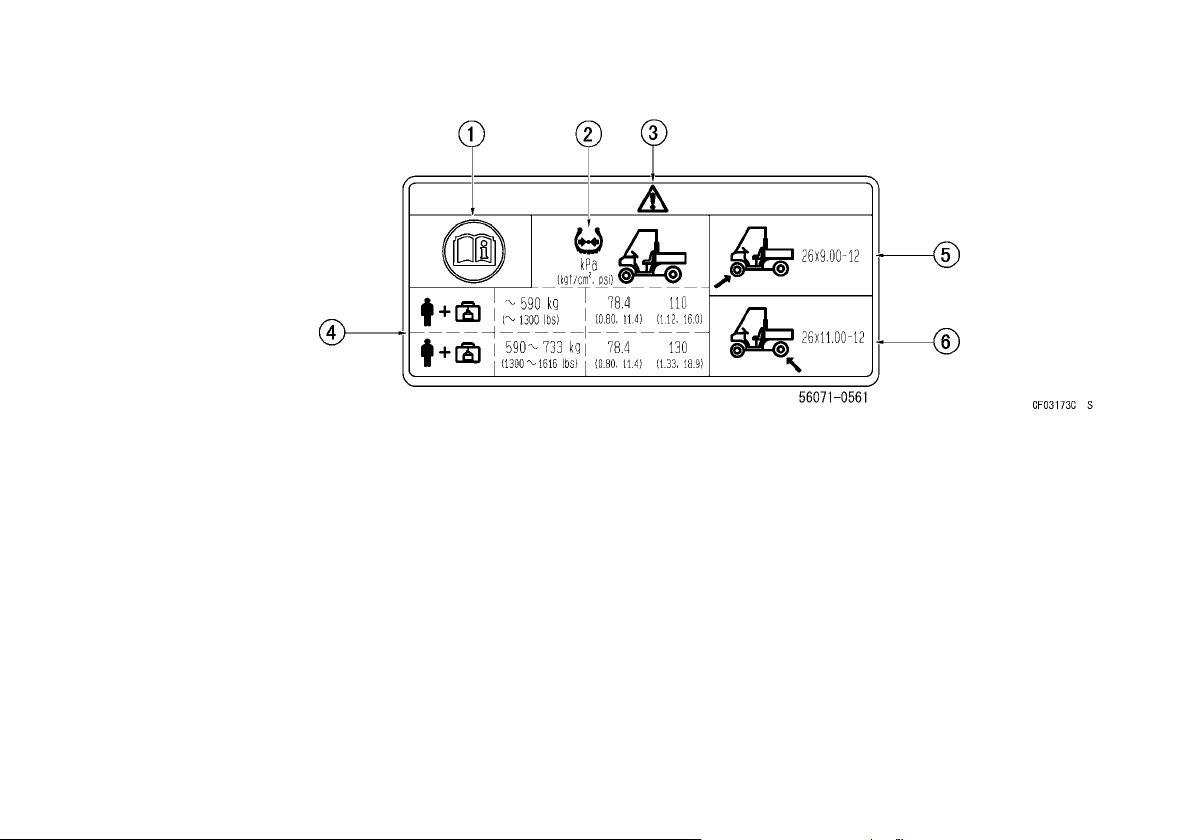
(13)
1. Read Owner’s Manual
2. Tire pressure
3. Safety alert symbol
4. Load condition (including occupants and cargo)
5. Front tire size
6. Rear tire size
LOCATION OF LABELS 55
Page 57
56 LOADING INFORMATION
LOADING INFORMATION
WARNING
Incorrect loading, improper installation or use
of accessories, or modification of your vehicle may result in an unsafe operating condition. Before you operate it, make sure that the
vehicle is not overloaded and that you have
followed these instructions.
With the exception of genuine Kawasaki Parts
and Accessories, Kawasaki has no control over the
design or application of accessories. In some cases,
improper installation or use of accessories, or vehicle modifications, will void the utility vehicle warranty. In selecting and using accessories, and in
loading the vehicle, you are personally responsible
for your own safety and the safety of other person(s)
involved.
NOTE
Kawasaki Parts and Accessories have been spe-
○
cially designed for us e on Kawasaki utility ve-
hicles. We strongly recommend that all parts and
accessories you add to your vehicle be genuine
Kawasaki components.
Because any vehicle is sensitive to increases in
weight and change s in weight distribution, you must
take ca re in carrying cargo. Always follow these precautions:
Carrying cargo, passengers and/or pulling a trailer
•
can make the vehicle difficult to steer and may affect vehicle handling in an unpredictable manner.
Use extreme caution when climbing and descending hills, and traversing slopes.
Braking distance is increased when carrying car-
•
go, passeng ers, and/or pulling a trailer. Reduce
speed and allow greater distance for braking.
All cargo should be carried as low as possible to
•
reduce the effect on the vehicle’s center of gravity.
Cargo weight should be equally distributed from
side to side. This helps maintain stability by centralizing weight. Avoid carrying cargo that extends
beyond the rear of the vehicle. Do not carry cargo
on top of the ROPS.
Cargo should be securely anchored. Make sure
•
the cargo will not move around while the vehicle is
moving. Recheck cargo security as often as possible (while the vehicle is stopped) and adjust as
necessary.
NOTICE
The front body work and fenders are not designed to carry cargo or to support weight.
Do not place cargo, lean or sit on them, or
they may break.
This vehicle is not designed to carry passengers
•
in the cargo bed. Installing additional passenger
Page 58
seating or carrying passengers in the cargo bed
can cause changes in vehicle handling.
WARNING
Passengers transported in the cargo bed can
be tossed about or even thrown out causing
serious injury or death. Do not install seating
or trans port passengers in the cargo bed.
(Maximum Cargo Bed Load) Do not carry more
•
than maxi mum cargo bed load as specified below.
kg ( lb)
(Maximum Vehicle Load) Weight of operator, pas-
•
senger(s), cargo, accessories, and trailer tongue
must not exceed following limits.
kg ( lb)
NOTE
Maximum cargo bed load and vehicle load for
○
your Mule are show in your English OM titled
“LOADING INFORMATION” chapter. Refer to the
relevant page and copy the data value into the
space provided in this page.
Do not operate this vehicle faster than 16 km/h
•
(10 mph) when pulling a trailer. Refer to the
“Trailer Hitch Bracket” section in the “GENERAL
INFORMATION” chapter.
LOADING INFORMATION 57
Page 59
58 GENERAL INFORMATION
GENERAL INFORMATION
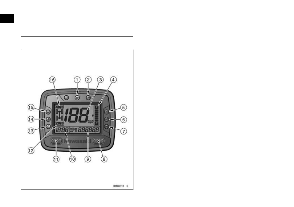
Multifunction Meter (KAF1000B/E)
1. Amber Glow Plug Indicator Light
2. Red EPS Warning Indicator Light
3. Speedometer
4. Fuel Level Gauge
5. Red Parking Brake Indicator Light
6. Red Reverse Indicator Light
7. Green Neutral Indicator Light
8. Right Button
9. Odometer/Trip Meters (Trip Meter A and B)/Hour
Meter
10.Clock
11. Left Button
12.“2WD” Indicator Symbol
13.Red Seat-Belt Use Reminder
14.Red Coolant Temperature Warning Indicator
Light
15.Red Oil Pressure Warning Indicator Light
16.“4WD” Indicator Symbol
Pushing the left button shifts the display in the
odometer/trip meters/hour meter through the 4
modes; odometer, trip meter A and B, and hour meter.
When the main switch is turned on, all the “LCD”
segments and “LED” lights are displayed for a second, then the clock and meters operate normally depending on the mode selected.
Page 60
GENERAL INFORMATION 59
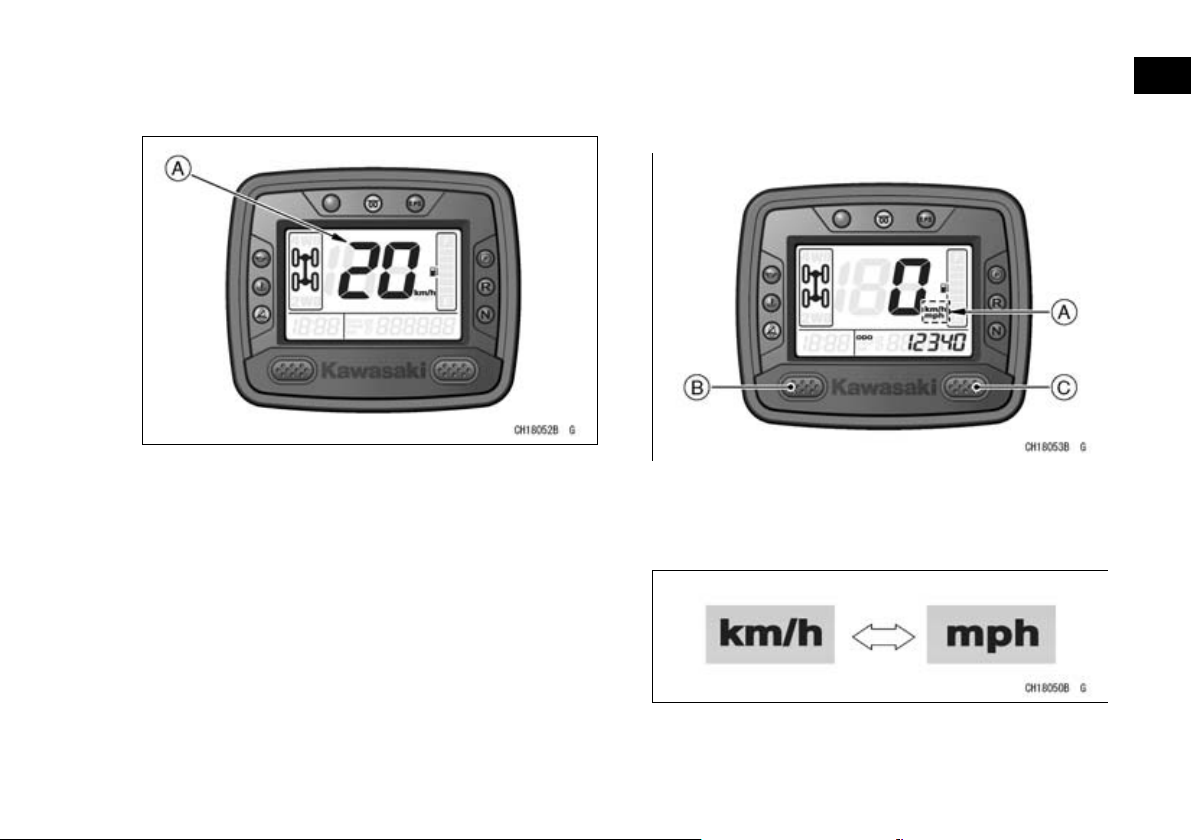
Speedometer
The speed ometer shows the speed of the vehicle.
A. Speedometer
mph·km/h Display:
mph·km/h display can alternate between English
and metric modes (mph and km/h) in the digital meter. Make sure that mph or km/h is correct ly displayed according to local regulations before driving.
Shift the mph·km/h display in the digital meter as follows.
The mph·km/h display shifts by pushing and hold-
•
ing the left button and pushing the right button
within two seconds.
A. mph·km/h Display
B. Left Button
C. Right Button
The mph·km/h display shifts as follows.
•
NOTE
Do not operate the vehicle with the digital meter
○
displaying in the wrong unit (mph or km/h).
Display the odometer in the digital meter.
•
NOTE
The data is maintained even if the battery is dis-
○
connected.
Page 61
60 GENERAL INFORMATION
Fuel Level Gauge
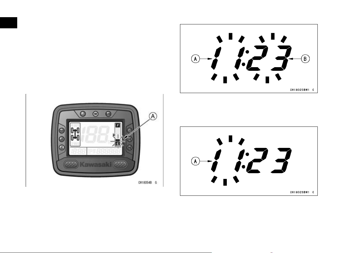
The fuel in the fuel tank is shown in segments. All
6 segments are displayed when the fuel tank is full.
As fuel is consumed the segments go out accordingly. When the bottom segment is reached, it will
begin blinking to warn of a low fuel level.
When it begins blinking, 6.6 liters (1.7 US gal) of
fuel remains. Fill the fuel tank as soon as possible
because there is no reserve tank in this vehicle (see
Fuel section).
A. Hour Display
B. Minute Display
Push the right button. The hour display only
•
blinks. Push the left button to advance the hours.
A. Blinking to warn of a low fuel level
Clock
To adjust hours and minutes:
Turn the main switch on.
•
The odometer is displayed.
•
Push the right button for more than two seconds.
•
Both the hour and minute displays start blinking.
A. Hour Display
Push the right button. The hour display stops
•
blinking and the minute display starts blinking.
Push the left button to advance the minutes.
Page 62
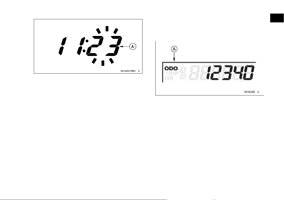
A. Minute Display
Push the right button. Both the hour and minute
•
displays start blinking again.
Push the left button. The displays stop blinking
•
and the clock starts working.
GENERAL INFORMATION 61
NOTE
When the figures come to 999999, they are
○
stopped and locked.
A. Odometer
NOTE
Pushing the left button momentarily advances the
○
hour or minute step by step. Pushing and holding
the button advances the hour or minute continuously.
The clock works normally from the back-up power
○
while the main switch is turned off.
When the battery is disconnected, the clock re-
○
sets to 1:00, and starts working again when the
battery is connected.
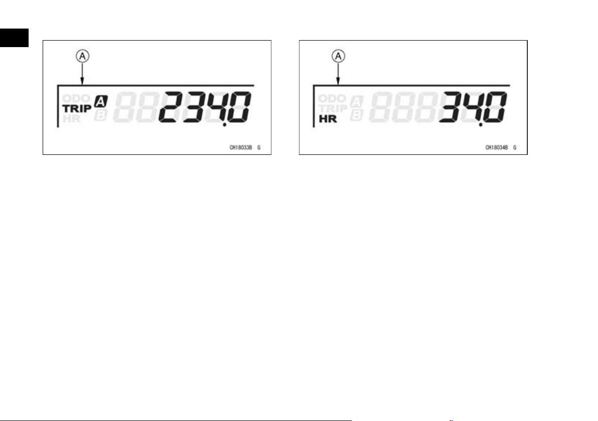
Odometer
The odometer shows the total distance in kilometers or miles that the vehicle has been driven.
The meter cannot be reset.
Trip Meters (Trip Meter A/B)
The trip meter shows the distance in kilometers or
miles traveled since it was last reset to zero.
To reset the trip meter:
Push the left button to display the trip meter A or
•
B.
Push the right button and hold it in.
•
After two seconds, the figure display turns to 0.0,
•
and then starts counting when the vehicle is oper-
ated. The meter counts until it is next reset.
NOTE
When the trip meter reaches 9999.9 when the ve-
○
hicle is running, it turns back to 0.0 and starts
counting again.
Page 63
62 GENERAL INFORMATION
A. Trip Meter A
Hour Meter
The hour meter shows the total hours that the vehicle has been operated. This meter cannot be reset.
NOTE
When the figures come to 99999.9, they are
○
stopped and locked.
A. Hour Meter
2WD/4WD Indicator Symbol
This vehicle can be driven in either “2WD” or
“4WD.”
When the selectable 2WD/4WD shift switch is in
“4WD,” the “4WD” indicator symbol will appear.
After shifting there is a momentary delay before
the indicator symbols change.
Page 64
GENERAL INFORMATION 63
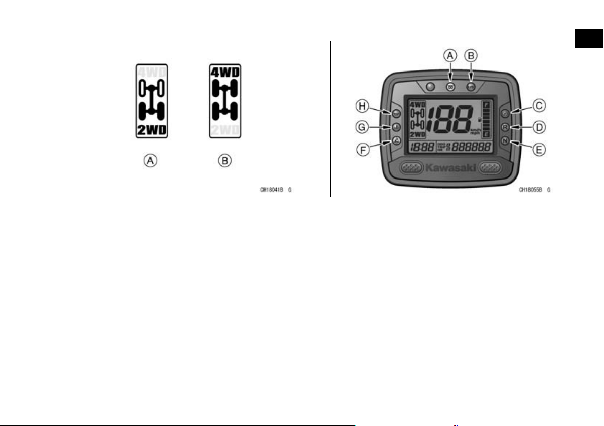
A. “2WD” Indicator Symbol
B. “4WD” Indicator Symbol
A. Amber Glow Plug Indicator Light
B. Red EPS Warning Indicator Light
C. Red Parking Brake Indicator Light
D. Red Reverse Indicator Light
E. Green Neutral Indicator Light
F. Red Seat-Belt Use Reminder
G. Red Coolant Temperature Warning Indicator
Light
H. Red Oil Pressure Warning Indicator Light
Amber Glow Plug Indicator Light
The glow plug indicator light goes on for 4 seconds when the main switch key is turned to the “ON”
position. The indicator light also goes on whenever
the key is in the “START” position. The indicator light
goes off after the plug is fully heated. If it does not
go on or go off, have the glow plug and related system checked by an authorized Kawasaki dealer.
Page 65

64 GENERAL INFORMATION
Refer to the “Starting the Engine” section in the
“HOW TO OPERATE” chapter for detailed informa-
tion.
Red EPS Warning Indicator Light
The EPS warning indicator light will momentarily
illuminate when the engine starts, then go off in a
second if the system is in order. If this warning indicator light illuminates any other time, it indicates the
ECU or actuator has malfunctioned, or the wiring
harness has become disconnected. Stop driving immediately and contact an authorized Kawasaki
dealer to have the system checked.
NOTE
If this warning indicator light does not go on when
○
the main switch is turned on, there may be a prob-
lem with the light itself. Contact an authorized Ka-
wasaki dealer for inspection.
Red Parking Brake Indicator Light
When the parking brake is applied with the main
switch in the “ON” position, the parking brake indicator light illuminates.
Red Reverse Indicator Light
When the transmission is in reverse gear, the reverse indicator light illuminates.
Green Neutral Indicator Light
When the transmission is in neutral, the neutral indicator light illuminates.
Red Seat-Belt Use Reminder
When the main switch is turned on, the seat-belt
use reminder will illuminate and stay on for approximately 8 seconds, even if the operator's belt is
buckled. The light is a reminder to the operator to
make sure that passengers have buckled their seat
belts.
Red Coolant Temperature Warning Indicator
Light
The coolant temperature warning indicator light illuminates whenever the coolant temperature rises
too high while the vehicle is in operation. If it stays
on, stop the engine and check the coolant level in
the coolant reserve tank after the engine cools
down.
Be sure to check that the radiator fan is free from
mud and other obstacles. Refer to the “Breaker”
section in the “MAINTENANCE AND ADJUSTMENT” chapter.
NOTICE
Do not continue running the engine with the
temperature warning indicator light continuously illuminated. Prolonged engine operation can result in engine damage from
overheating.
NOTE
When you touch the fan, be sure to disconnect
○
the negative ( –) battery cable, since the fan can
Page 66
GENERAL INFORMATION 65
operate automatically even with the main switch
off.
Red Oil Pressure Warning Indicator Light
The oil pressure warning indicator light blinks to
warn the oper ator whenever the oil pressure is dangerously low or the main switch is in the “ON” position with the engine not running, and goes off when
the proper engine oil pressure is reached. Refer to
the “MAINTENANCE AND ADJUSTMENT” chapter
for more detailed engine oil information.
Lighting/Electrical Accessory Connector (KAF400A/B)
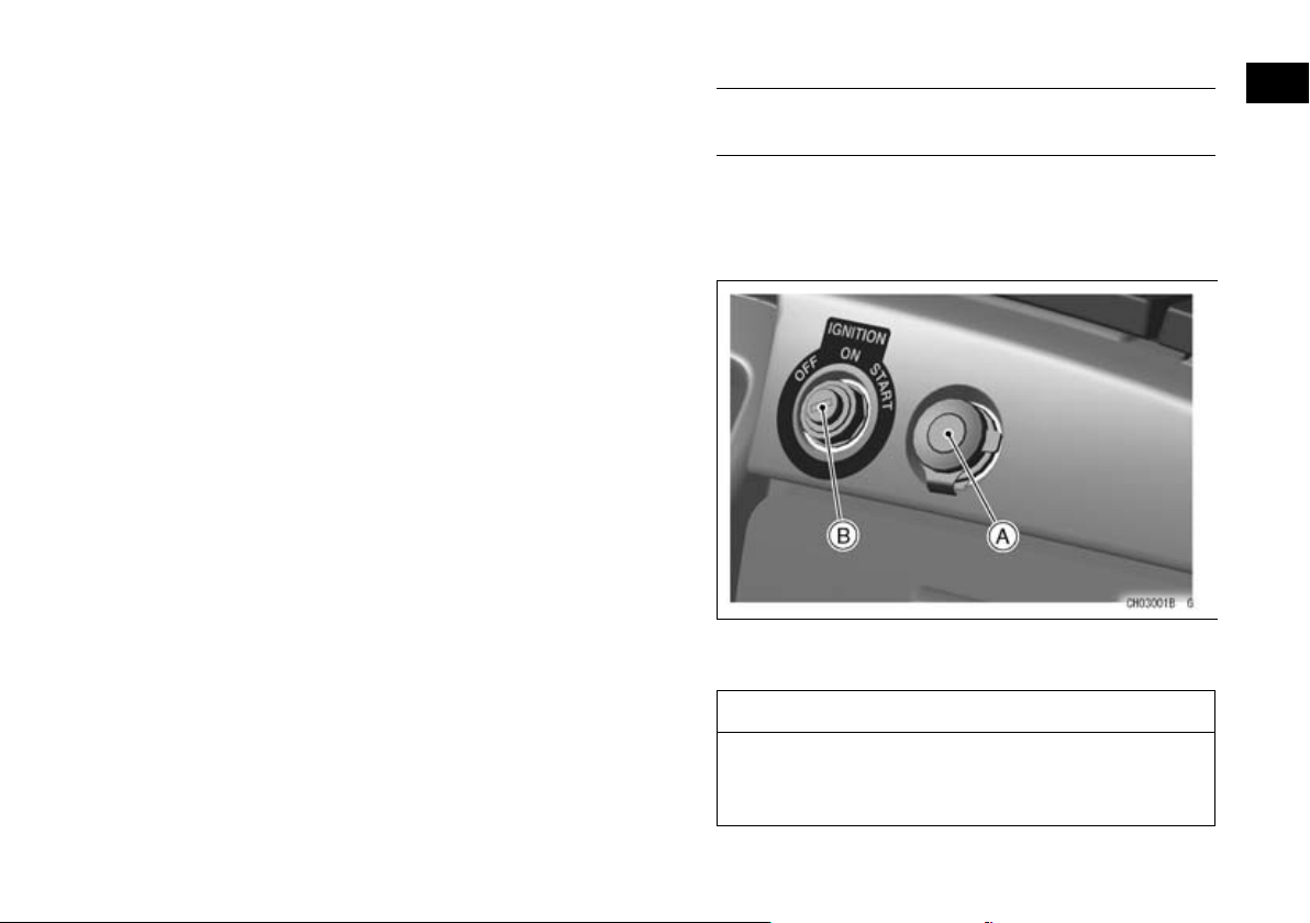
The lighting/electrical accessory 12 volt connector
is located on the dashboard.
An auxiliary light or an accessory may be con-
nected to this connector.
A. Accessory Connector
B. Ignition Switch
NOTICE
Do not connect a light or load of more than
120 watts to these connectors, or the battery
may become discharged very rapidly.
Page 67
66 GENERAL INFORMATION
Lighting/Electrical Accessory Socket (KAF1000B/E)
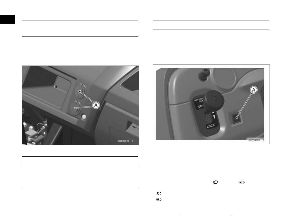
The lighting/electrical accessory 12 volt sockets
are located on the dashboard.
An auxiliary light or an accessory may be con-
nected to these connectors.
A. Power Outlet Sockets
NOTICE
Do not connect a light or load of more than
120 watts on one or both sockets, or the battery may rapidly discharge.
Light Switches
(KAF400A/B)
Turn on the headlights and taillights by pushing
the light switch in, with the ignition switch key in the
“ON” position.
The lights go off when the switch is pushed again.
A. Light Switch
(KAF1000B/E)
The light switches are 3-position type with an indicator.
The headlights can be turned on by pushing the
headlight switch to the “
when the main switch is in the “ON” position.
: Low Beam
: High Beam
” or “ ” position
Page 68
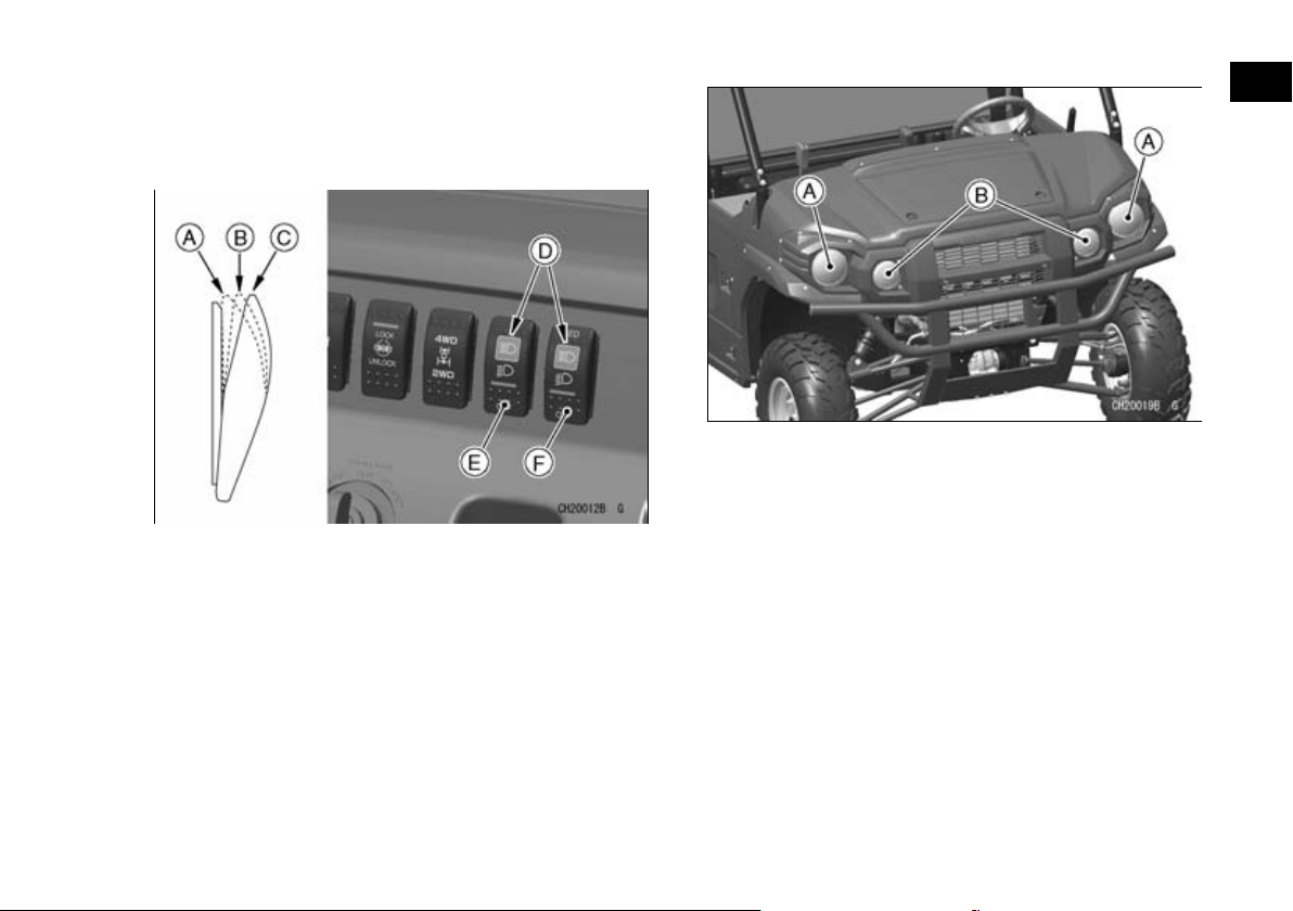
When the headlights are on high beam, the high
beam indicator light in the switch goes on as a reminder. The headlights go off when the headlight
switch is pushed in “OFF” position.
A. High Beam Position
B. Low Beam Position
C. OFF Position
D. High Beam Indicators
E. Headlight Switch
F. LED Sub Headlight Switch
This vehicle is equipped with LED sub headlights.
The operation of the LED sub headlight switch is
similar with the headlight switch.
GENERAL INFORMATION 67
A. Headlights
B. LED Sub Headlights
Page 69
68 GENERAL INFORMATION
Steering Wheel (KAF1000B/E)
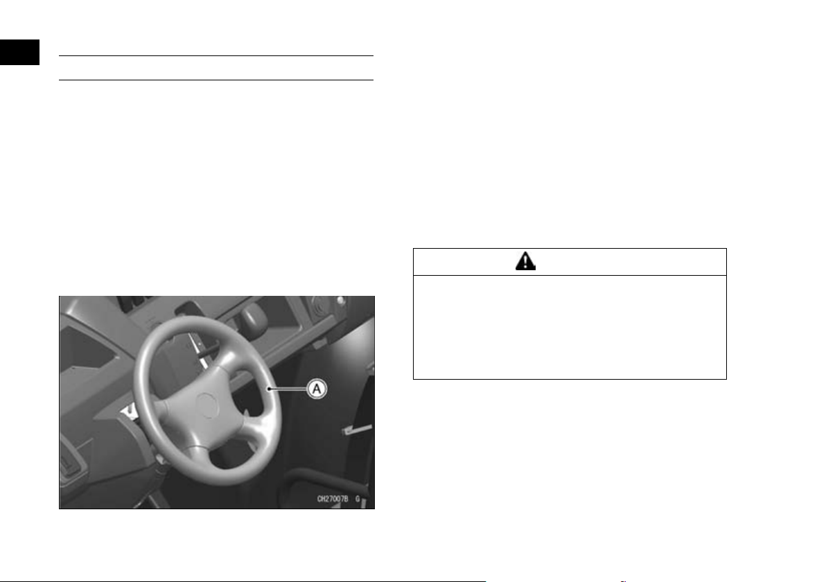
This vehicle is equipped with an electric power
steering system. The system does not require regular maintenance by users. Do not tamper with the
electronic control unit (ECU) or loosen the fittings of
steering actuator, or the neutral position setting of
the steering will be adversely affected and will
cause serious driving problems. If such components
need service, contact an authorized Kawasaki dealer.
If the steering becomes more difficult than usual
or you feel a steering problem, refer to the “Steering
Wheel” section in the “MAINTENANCE AND ADJUSTMENT” chapter.
NOTE
The power steering system functions only when
○
engine is running.
If you install wireless equipment on board, contact
○
an authorized Kawasaki dealer. Installing such
equipment improperly may affect the ECU.
Steering Position Adjustment
The steering wheel position can be adjusted to
suit the operator.
Make any steering wheel adjustment before start-
ing the vehicle.
WARNING
Adjusting the steering wheel position while
driving could cause loss of control and an accident resulting in serious injury or death. To
prevent loss of control, do not adjust the
steering wheel position unless the vehicle is
stopped.
Move the steering wheel up or down while pulling
•
up the tilt lock lever under the steering wheel.
Release the tilt lock lever to lock the steering
•
wheel in position.
A. Steering Wheel
Page 70
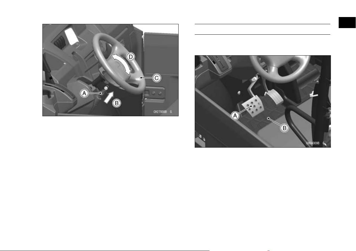
A. Tilt Lock Lever
B. Pull up.
C. Steering Wheel
D. Adjusting Direction
GENERAL INFORMATION 69
Brake Pedal
The brake pedal is the left pedal on the floorboard.
Depress the pedal to slow or stop the vehicle.
NOTE
Make sure you have securely locked the steering
○
wheel in place by moving it up and down.
A. Brake Pedal
B. Floorboard
Page 71
70 GENERAL INFORMATION
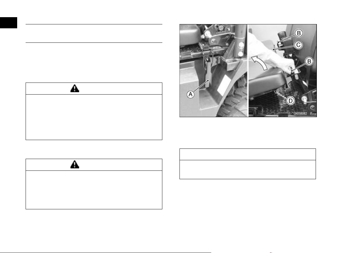
Converting Rear Seat and Cargo Bed (KAF1000B)
This vehicle can be converted to accommodate
more passengers and less cargo or fewer passengers and more cargo.
The seats and the cargo bed can be converted in
the following way.
WARNING
The latches must be unlocked durin g the converting operation, allowing the possibility for
the cargo bed to suddenly lift and cause serious injury. To prevent the cargo bed from
suddenly lifting, do not convert the rear seat
with the cargo bed loaded.
A. Cargo Bed Latch (Both Sides)
B. Handgrips
C. Rear Seat Cushion
D. Plastic Seat Base
From 4-P ersons to 2-Persons Mode
WARNING
Fingers or hands could be pinched during
cargo bed conversion. When converting the
cargo bed, be careful not to catch fingers,
hands, or any other body parts between the
folding bed side walls.
1. Open the rear doors and release the cargo bed
latches on both sides.
2. Lift the rear seat by holding the handgrip on ei-
ther side, and turn the rear seat forward.
NOTICE
Do not lift the rear seat using the plastic seat
base as it will break the plastic seat base.
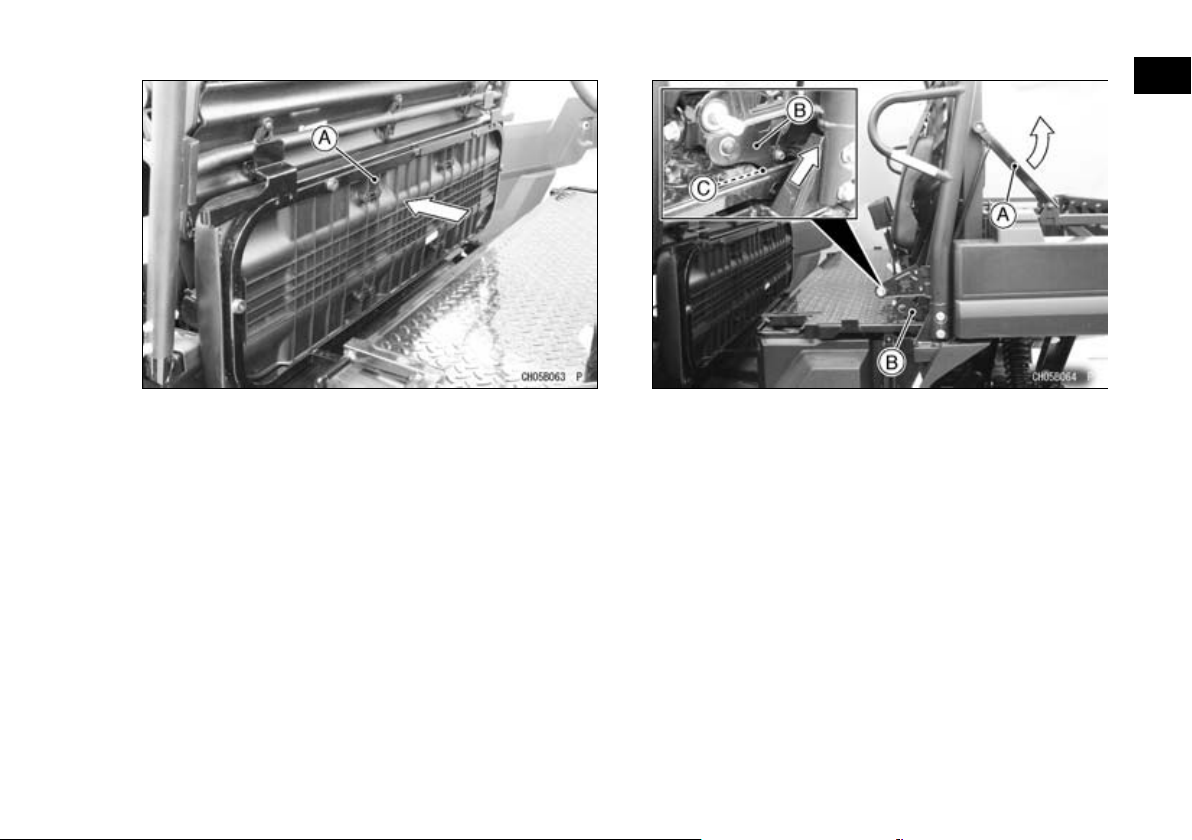
3. Push the rear seat frame forward into the stored
position.
Page 72
GENERAL INFORMATION 71
A. Rear Seat Frame (Stored Position)
4. On both sides, pull the lower end of the screen
lock arms to release it from the cargo bed frame.
5. Turn the screen lock arms upward until lower
locking arm is released from the lock pin in the
cargo bed base.
A. Screen Lock Arm (Both Sides)
B. Lower Locking Arm (Both Sides)
C. Lock Pin (Both Sides)
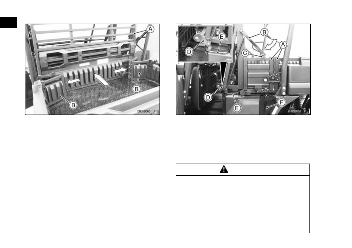
6. Slide the cargo bed screen forward in conjunction with pushing the hinge between the cargo
bed side plates on both sides.
NOTE
To move the screen smoothly, push both cargo
○
bed side plates evenly as much as possible.
Page 73
72 GENERAL INFORMATION
A. Cargo Bed Screen
B. Cargo Bed Side Plates
7. After fully extending the cargo bed side plates,
lower both screen lock arms, aligning their lower
locking arms with the lock pins in the cargo bed
base.
8. Push the screen lock arms into the brackets on
the side plates on both sides until you hear a
click.
NOTE
Pull the screen lock arms lightly to check if they
○
are locked securely.
9. Secure the cargo bed side plates with the cargo
bed latches on both sides.
A. Cargo Bed Side Plates
B. Screen Lock Arm
C. Bracket
D. Lower Locking Arm
E. Handgrip
F. Cargo Bed Latch
10.Close the rear doors.
WARNING
Failure to properly lock the cargo bed or
screen may allow them to move suddenly
while driving, causing loss of control and an
accident resulting in serious injury or death.
To prevent the cargo bed from suddenly moving, make sure that the cargo bed and screen
has been locked properly after handling
them.
Page 74
From 2-P ersons to 4-Persons Mode
WARNING
Fingers or hands could be pinched during
cargo bed conversion. When converting the
cargo bed, be careful not to catch fingers,
hands, or any other body parts between the
folding bed side walls.
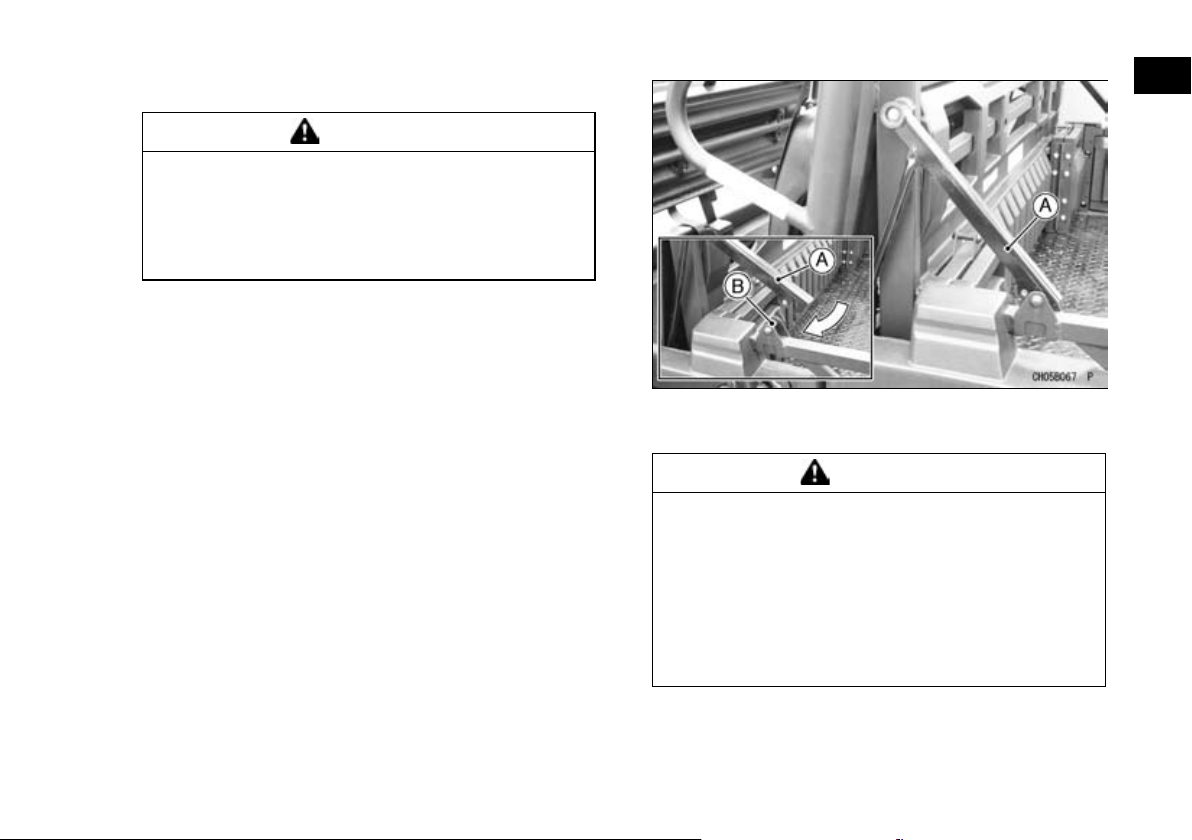
Reverse the procedure for 4-persons to 2-persons
•
mode conversion.
NOTE
After folding the cargo bed side plates, push both
○
screen lock arms to the lock pin until you hear a
click.
GENERAL INFORMATION 73
A. Screen Lock Arm
B. Lock Pin
WARNING
Failure to properly lock the cargo bed or
screen may allow them to move suddenly
while driving, causing loss of control and an
accident resulting in serious injury or death.
To prevent the cargo bed from suddenly moving, make sure that the cargo bed and screen
has been locked properly after handling
them.
Page 75
74 GENERAL INFORMATION
Cargo Bed
Tailgate
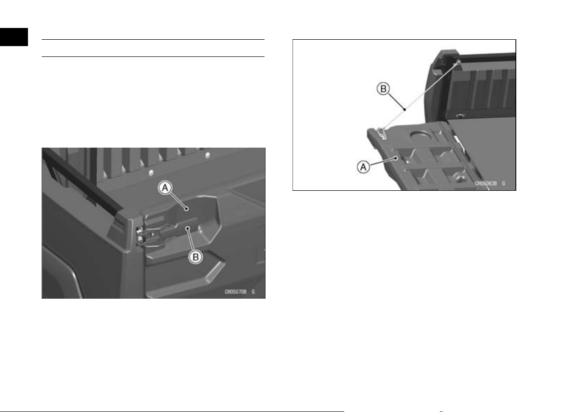
The tailgate of the cargo bed can be lowered. Before lowering the tailgate, park on a firm level surface and set the parking brake.
To open the tailgate, release the latches and lower
the tailgate. Cables hold the tailgate level with the
cargo bed.
A. Tailgate
B. Latch Handle (Both Sides)
To close the tailgate, lift to the upright position and
secure firmly with the latches.
Push the tailgate latch handles forward to make
sure the latches stay securely closed. Do not drive
the vehicle with the tailgate lowered.
A. Tailgate
B. Cable
Cargo Bed
(KAF400A/B)
The cargo bed can be tilted by releasing the
latches on right side, and then lifting the bed with
the handgrip. Before tilting the cargo bed, park on a
firm level surface and set the parking brake.
After lifting the bed, support the bed in the tilted
position with the supporting rod provided on the bottom of the cargo bed.
To lower the bed, check to be sure the area under
the cargo bed is clear, then carefully lower the bed
into position.
Latch the latch and check that the bed is properly
locked into place. Do not leave the cargo bed unlatched.
Page 76
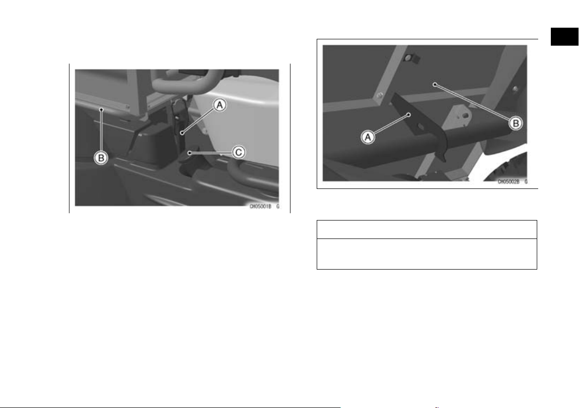
Do not drive the vehicle with the front end of the
cargo bed raised or unlatched.
A. Latch (locked position)
B. Handgrip
C. Fuel Tank Cap
GENERAL INFORMATION 75
A. Supporting Rod
B. Cargo Bed Bottom (Tilted Condition)
NOTICE
Do not carry more than 181 kg (400 lb) in the
cargo bed.
Page 77
76 GENERAL INFORMATION
WARNING
Overloading, failure to properly secure car-
•
go, or improper use of the cargo bed can
cause changes in handling which can lead
to an accident. Follow guidelines provided
in the “LOADING INFORMATION” chapter.
Passengers riding in the cargo bed can be
•
tossed about or even thrown out causing
serious injury or death. Do not install seating or carry passengers in the cargo bed.
Driving with the cargo bed tilted may be
•
hazardous. Failure to lower and lock the
bed into place may cause severe injury or
death. Al ways lower and latch the bed after
tilting.
Lifting and lowering the bed could be dan-
•
gerous. Be careful not to catch any part of
your body, such as hands or arms, between
the bed and ROPS or vehicle frame when
lifting and lowering the bed.
Loading Cargo Bed
(KAF1000B)
WARNING
Loading the cargo bed before the conversion
operation is completed and the cargo bed is
unlocked may cause the bed to suddenly tilt,
resulting in serious injury. To prevent the bed
from suddenly lifting, be sure the conversion
is complete and the cargo bed latches are
firmly locked.
NOTICE
Do not carry mo re than the maximum load
stated here in the convertible cargo bed.
Short bed mode: 158 kg (350 lb)
•
Long bed mode: 453 kg (1 000 lb)
•
Page 78
GENERAL INFORMATION 77
WARNING
Overloading, failure to properly secure car-
•
go, or improper use of the cargo bed can
cause changes in handling which can lead
to an accident. Follow guidelines provided
in the “LOADING INFORMATION” chapter.
Passengers transported in the cargo bed
•
can be tossed about or even thrown out
causing serious injury or death. Do not install seating or transport passengers in the
cargo bed.
Driving with the cargo bed tilted may be
•
hazardous. Failure to lower and lock the
bed into place may cause serious injury or
death. Al ways lower and latch the bed after
tilting.
Lifting and lowering the bed could be dan-
•
gerous. Be careful not to catch any part of
your body, such as hands or arms, between
the bed and ROPS or vehicle frame when
lifting and lowering the bed.
(KAF1000E)
NOTICE
Do not carry more than 453 kg (1 000 lb) in the
cargo bed.
WARNING
Overloading, failure to properly secure car-
•
go, or improper use of the cargo bed can
cause changes in handling which can lead
to an accident. Follow guidelines provided
in the “LOADING INFORMATION” chapter.
Passengers transported in the cargo bed
•
can be tossed about or even thrown out
causing serious injury or death. Do not install seating or transport passengers in the
cargo bed.
Driving with the cargo bed tilted may be
•
hazardous. Failure to lower and lock the
bed into place may cause serious injury or
death. Al ways lower and latch the bed after
tilting.
Lifting and Lowering the Cargo Bed
(KAF1000B)
The cargo bed can be tilted by releasing the
latches on each side, and then lifting the bed with
the handgrips. Before tilting the cargo bed, park on
a firm level surface and set the parking brake.
Empty the cargo bed prior to raising the cargo
bed.
Support the bed in the tilted position with the supporting damper and supporting rod provided on the
bottom of the cargo bed. Do not drive the vehicle
with the front end of the cargo bed raised or unlatched.
Page 79
78 GENERAL INFORMATION
To lower the bed, check to be sure the area under
the front of the cargo bed is clear, then carefully lower the bed into position.
Check that both latches have locked the bed into
place. Do not leave the cargo bed unlatched.
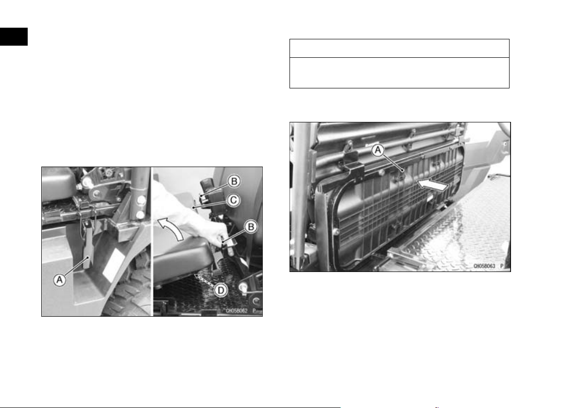
Lifting the Cargo Bed while in Short Configura-
tion
1. Open the rear doors and release the cargo bed
latches on both sides.
2. Lift the rear seat by holding the handgrip on ei-
ther side, and turn the rear seat forward.
A. Cargo Bed Latch (Both Sides)
B. Handgrips
C. Rear Seat Cushion
D. Plastic Seat Base
NOTICE
Do not lift the rear seat using the plastic seat
base as it will break the plastic seat base.
3. Push the rear seat frame forward into the stored
position.
A. Rear Seat Frame (Stored Position)
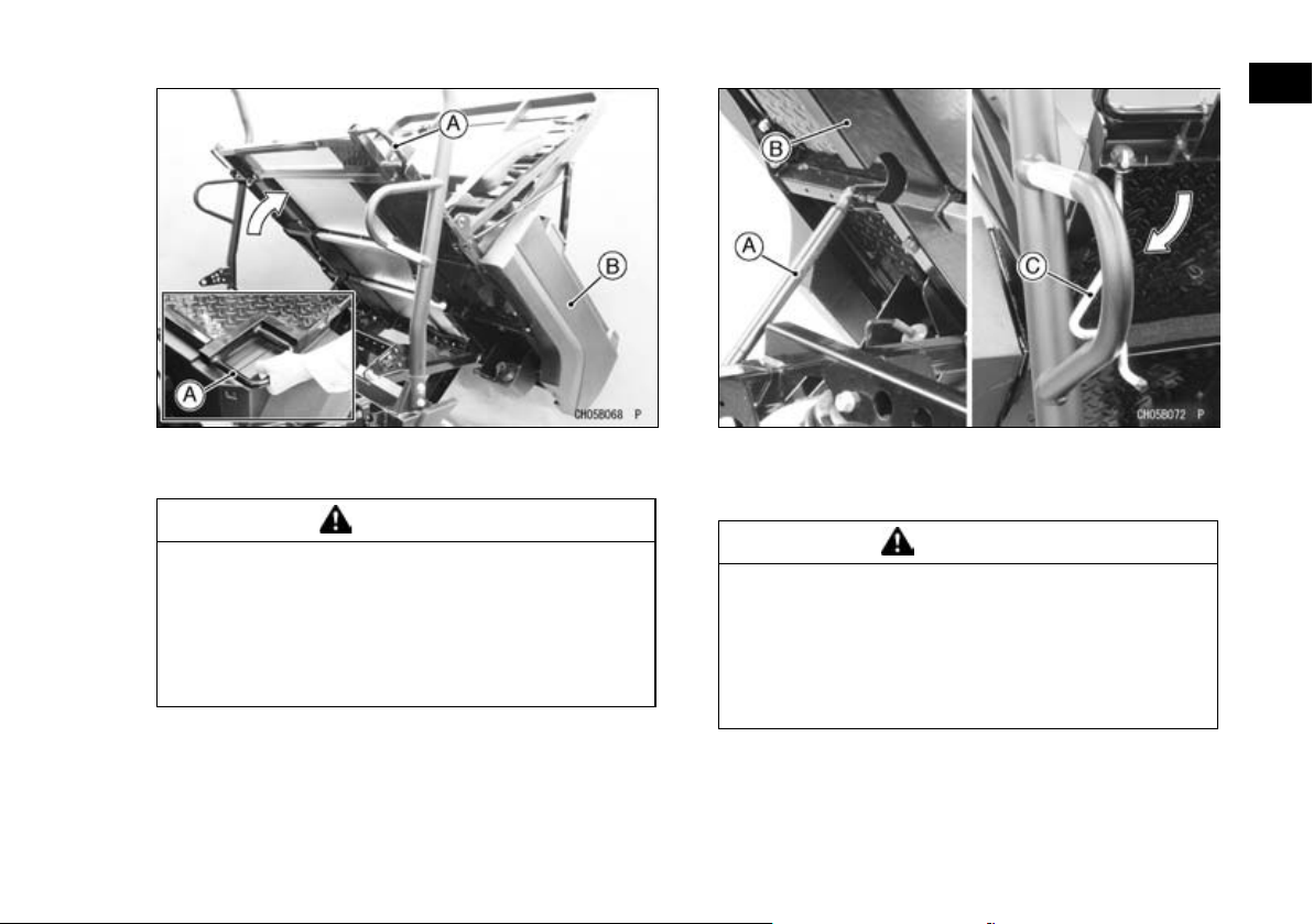
4. Hold the handgrip as shown. Holding the handgrip, lift the cargo bed carefully.
Page 80
GENERAL INFORMATION 79
A. Handgrip
B. Cargo Bed
WARNING
Reduced clearance between the cargo bed
and the ROPS can cause arm injury when lifting or lowering the cargo bed. To avoid injury,
grasp cargo bed at the handle and do not hold
the ROPS when lifting or lowering the cargo
bed.
5. Pull the supporting rod out of its clip and securely
hook the curved end of the supporting rod onto
the bar of the ROPS to support the cargo bed.
A. Supporting Damper
B. Cargo Bed (Raised Position)
C. Supporting Rod
WARNING
Using only the bed supporting damper for
cargo bed support may allow the cargo bed to
suddenly lower. To prevent injury caused by
sudden lowering of the cargo bed, support
the cargo bed with the support rod whenever
lifting the cargo bed.
Lifting the Cargo Bed in Extended Configura-
tion
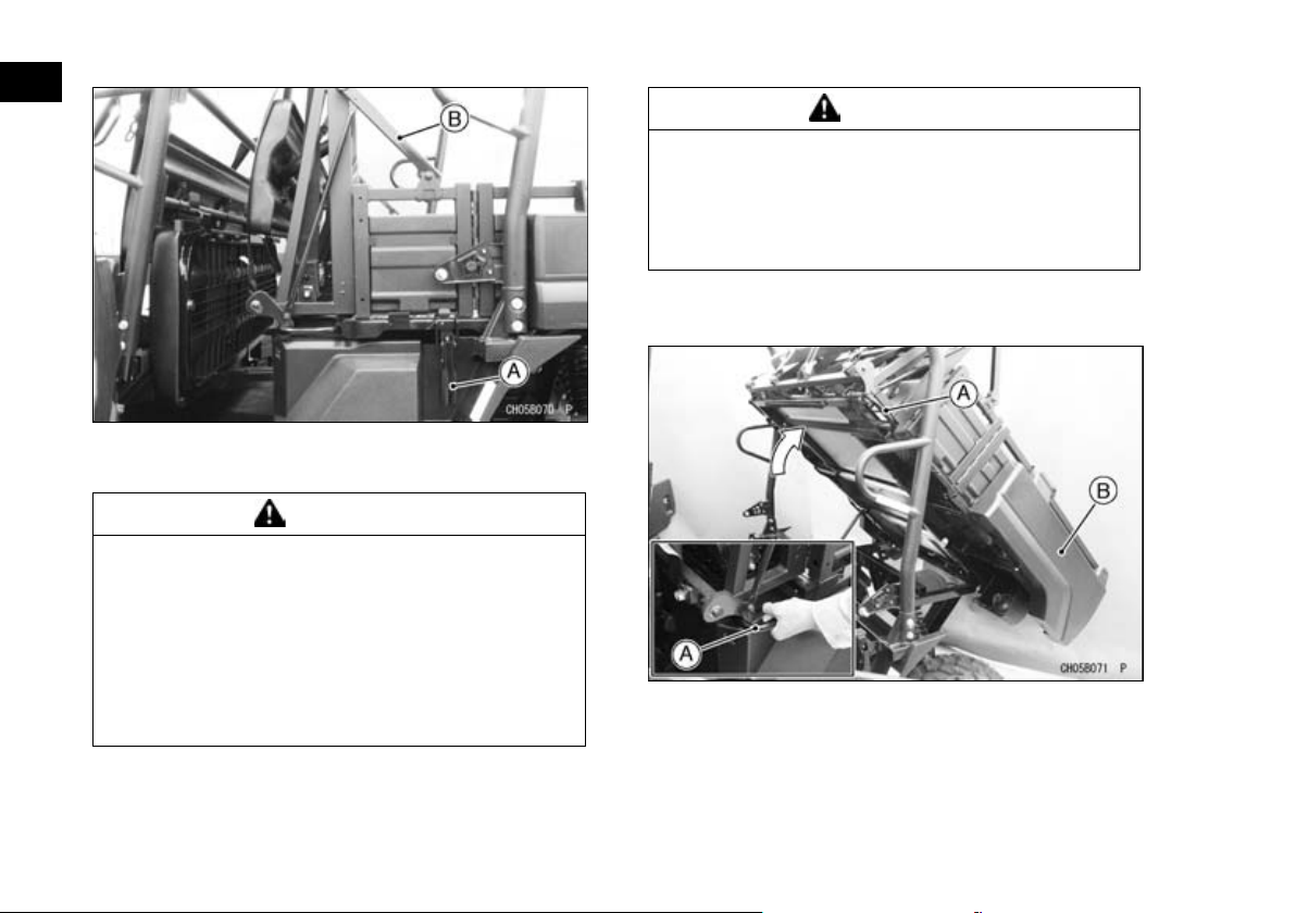
1. Open the rear doors. Make sure the screen lock
arms are locked properly then release the cargo
bed latches on both sides.
Page 81
80 GENERAL INFORMATION
A. Cargo Bed Latch (Both Sides)
B. Screen Lock Arm (Both Sides)
WARNING
Failure to properly lock the screen lock arms
could cause the cargo bed side plates to fold
and allow the screen to slide down while lifting the cargo bed, resulting in serious injury.
To prevent the cargo screen from sliding
down, make sure that the screen lock arms
are locked properly before lifting the cargo
bed.
WARNING
The front of the cargo bed becomes heavier
in the extended mode and may raise and lower more quickly, increasing the risk of arm injury. To prevent injury, use extra care when
raising or lowering the bed in extended mode.
2. Hold the handgrip as shown. Holding the handgrip, lift the cargo bed carefully.
A. Handgrip
B. Cargo Bed
Page 82
GENERAL INFORMATION 81
WARNING
Reduced clearance between the cargo bed
and the ROPS can cause arm injury when lifting or lowering the cargo bed. To avoid injury,
grasp cargo bed at the handle and do not hold
the ROPS when lifting or lowering the cargo
bed.
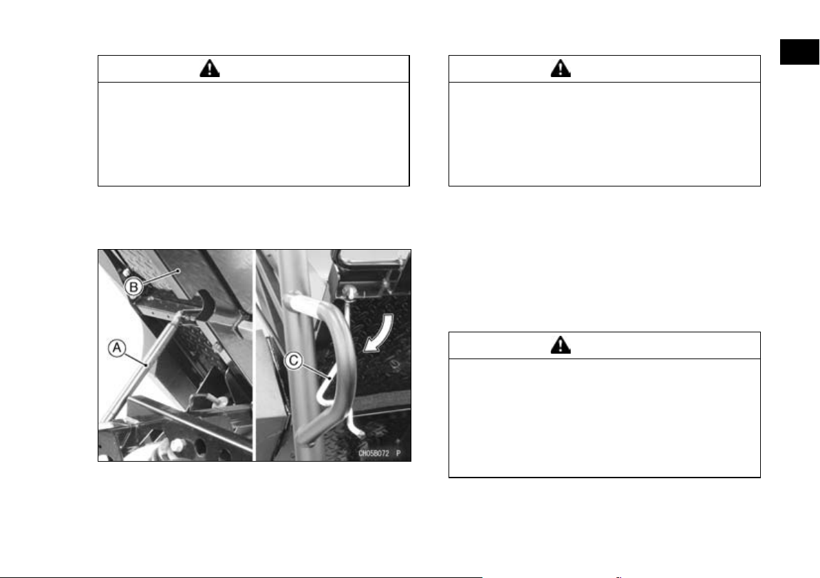
3. Pull the supporting rod out of its clip and securely
hook the curved end of the supporting rod onto
the bar of the ROPS to support the cargo bed.
A. Supporting Damper
B. Cargo Bed (Raised Position)
C. Supporting Rod
WARNING
Using only the bed supporting damper for
cargo bed support may allow the cargo bed to
suddenly lower. To prevent injury caused by
sudden lowering of the cargo bed, support
the cargo bed with the support rod whenever
lifting the cargo bed.
Lowering the Cargo Bed
Before lowering the bed, check to be sure the
area under the front of the cargo bed is clear. Return
the supporting rod to the original position and secure it with the clip. Hold the handgrip and carefully
lower the bed into position. Check that both latches
have locked the bed into place. Do not leave the
cargo bed unlatched.
WARNING
The front of the cargo bed becomes heavier
as it lowers into position and can suddenly
lower, trapping arms between the bed and
frame causing serious injury. To prevent the
bed from suddenly lowering, use the handles
to properly support the bed when lowering or
lifting the bed.
NOTE
To lower the cargo bed, follow the reverse proce-
○
dure for lifting. Be sure to restore the seat as
Page 83
82 GENERAL INFORMATION
before and put the latches on. Never drive the
Mule without locking the latches to the cargo bed.
WARNING
Overloading, failure to properly secure car-
•
go, or improper use of the cargo bed can
cause changes in handling which can lead
to an accident. Follow guidelines provided
in the “LOADING INFORMATION” chapter.
Passengers transported in the cargo bed
•
can be tossed about or even thrown out
causing serious injury or death. Do not install seating or transport passengers in the
cargo bed.
Driving with the cargo bed tilted may be
•
hazardous. Failure to lower and lock the
bed into place may cause serious injury or
death. Al ways lower and latch the bed after
tilting.
Lifting and lowering the bed could be dan-
•
gerous. Be careful not to catch any part of
your body, such as hands or arms, between
the bed and ROPS or vehicle frame when
lifting and lowering the bed.
(KAF1000E)
WARNING
Reduced clearance between the cargo bed
and the cargo screen ma y trap and seriously
injure an arm while lifting or lowering the cargo bed. To avoid possible injury, do not place
hands on any part of the cargo screen when
lifting or lowering the cargo bed.
The cargo bed can be tilted by releasing the
latches on each side, and then lifting the bed with
the handgr ips.
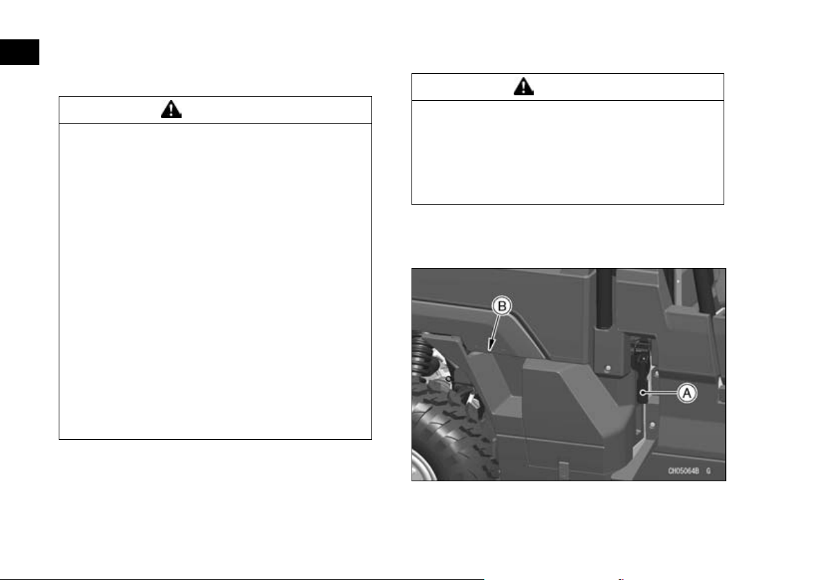
A. Cargo Bed Latch (Both Sides)
B. Handgrip (Both Sides)
Page 84
Lifting the Cargo Bed
Before tilting the cargo bed, park on a firm level
•
surface and set the parking brake.
Empty the cargo bed prior to raising the cargo
•
bed.
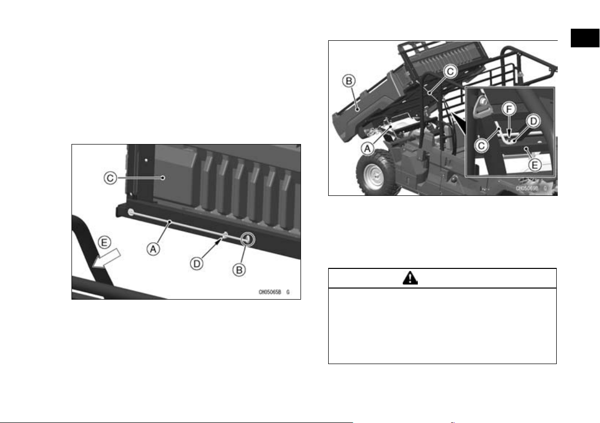
Lift the bed with the handgrips. The supporting
•
damper under the cargo bed helps lifting the bed.
Pull the supporting rod out of its mounting clip on
•
the front of the cargo bed.
GENERAL INFORMATION 83
A. Supporting Damper
B. Cargo Bed (Tilted Position)
C. Supporting Rod
D. Ring of the supporting rod
E. Screen
F. Stopper Pin
WARNING
A. Supporting Rod
B. Pull here to free rod from clip.
C. Cargo Bed
D. Clip
E. Forward
With the cargo bed at the highest position, hook
•
the ring of the supporting rod on the stopper pin of
the bottom horizont al bar of the screen.
Using only the bed supporting damper for
cargo bed support may allow the cargo bed to
suddenly lower. To prevent injury caused by
sudden lowering of the cargo bed, support
the cargo bed with the support rod whenever
lifting the cargo bed.
Page 85
84 GENERAL INFORMATION
Lowering the Cargo Bed
Before lowering the bed, check to be sure the
•
area under it is clear.
Return the supporting rod to its original position
•
and secure it with the clip.
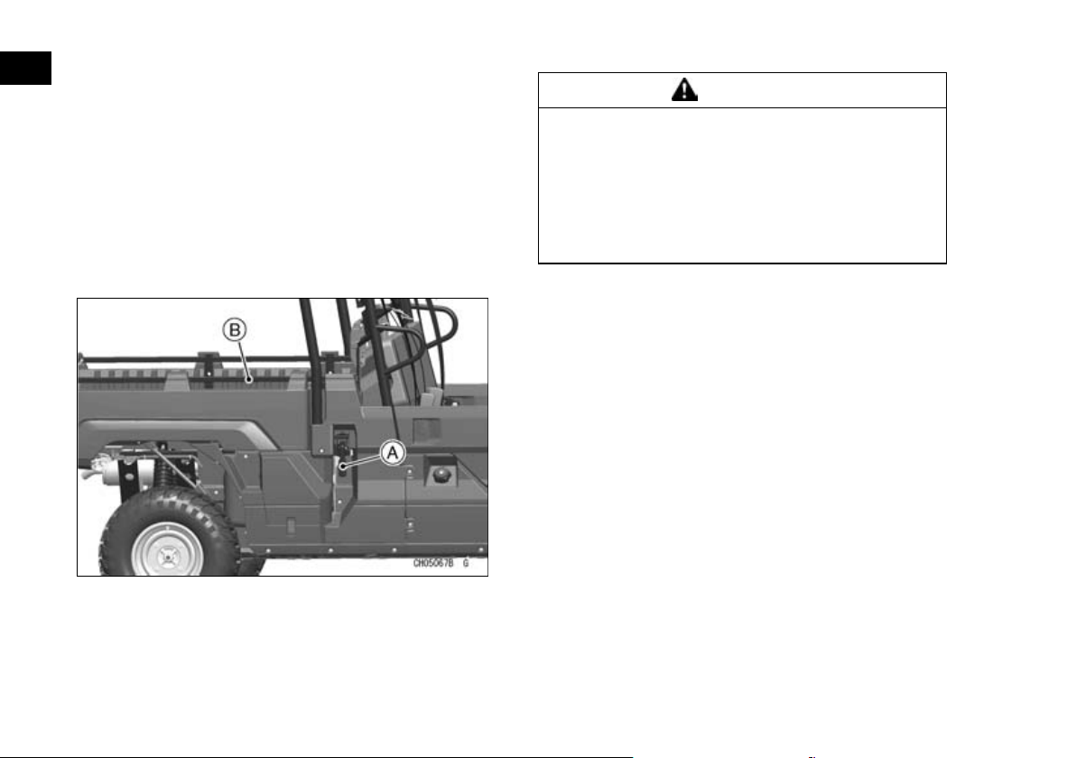
To lower the cargo bed pus h down the side rail of
•
the cargo bed. And then hold the handgrip with
another hand and carefully lower the bed in place.
Latch both latches and check that the bed is prop-
•
erly locked into place. Do not leave the cargo bed
unlatched.
A. Cargo Bed Latch (Locked Position)
B. Side Rail
Do not drive the vehicle with the front end of the
•
cargo bed raised or unlatched.
WARNING
The front of the cargo bed becomes heavier
as it lowers into position and can suddenly
lower, trapping arms between the bed and
frame causing serious injury. To prevent the
bed from suddenly lowering, use the handgrips to properly support the bed when lowering or lifting the bed.
Page 86
GENERAL INFORMATION 85
Choke Knob (KAF400A/B)
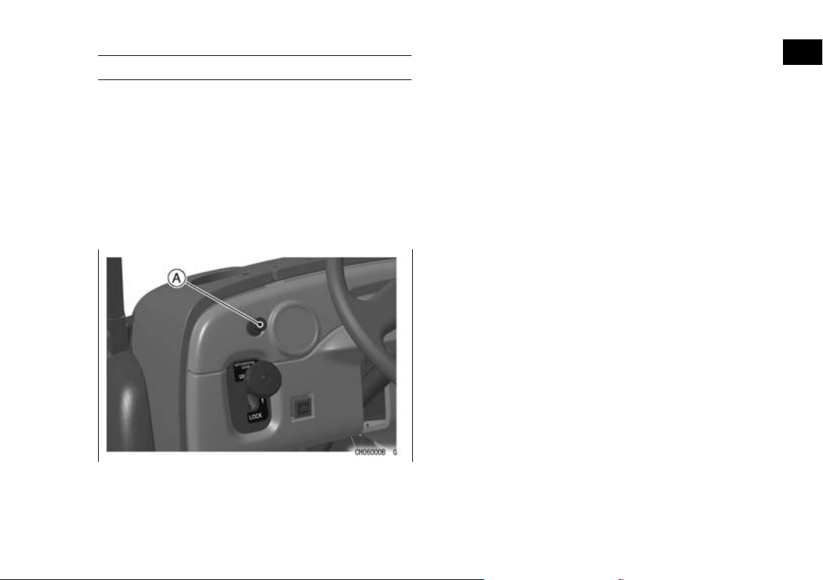
The choke knob located on the dashboard, to the
left of the steering wheel, provides a rich mixture for
cold starting.
Pull the choke knob all the way to start the engine.
Warm the engine up using the choke and throttle
until the idle speed is stable, and then push the
choke knob back.
Refer to the “Starting the Engine” section in the
“HOW TO OPERATE” chapter for detailed information.
NOTE
If the choke is left on (pulled out) after the engine
○
has warmed up, spark plug fouling and poor fuel
economy may result.
A. Choke Knob
Page 87
86 GENERAL INFORMATION
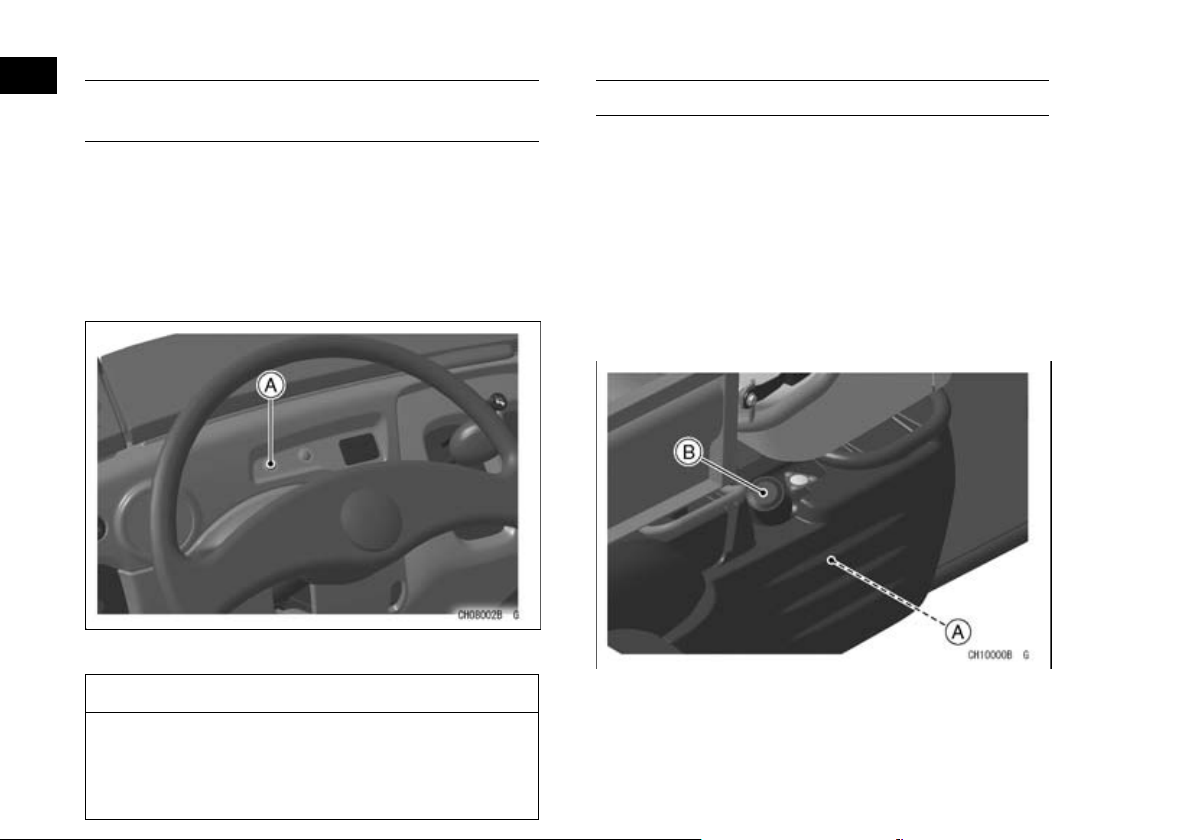
Engine Oil Temperature Warning Light (KAF400A)
The oil temperature warning light comes on whenever the engine oil temperature rises too high while
the vehicle is in operation. If it stays on, stop the engine and check the engine oil level after the engine
cools down.
Refer to the “Engine Oil” section in the “MAINTENANCE AND ADJUSTMENT” chapter.
A. Engine Oil Temperature Warning Light
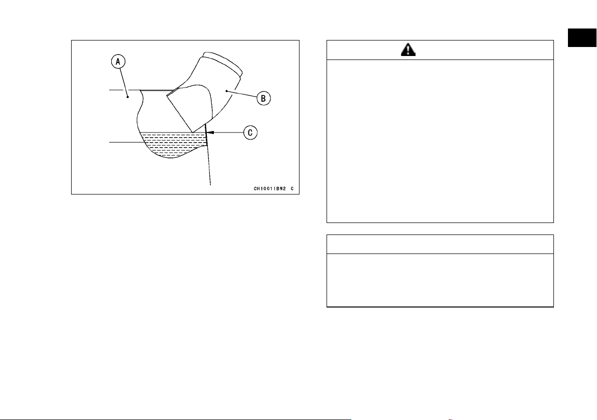
Fuel Tank (KAF400A/B)
Filling the Tank:
The fuel tank is mounted under the right end of
the seat. The gasoline octane rating listed is recommended. Avoid filling the tank in the rain or where
heavy dust is blowing, so that the fuel does not get
contaminated.
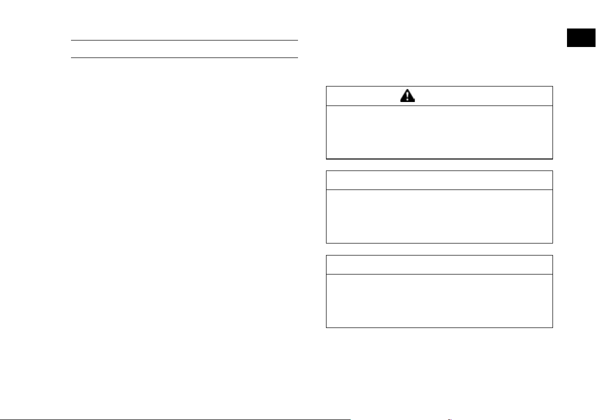
Never fill the tank completely to the top. As the
fuel expands in a warm tank, it may overflow from
the vent hose. After refueling, make sure the filler
cap is closed securely.
NOTICE
Do not let the engine continue runni ng with a
warning light on. Prolonged engine opera tion
can result in engine damage from overheat ing.
A. Fuel Tank
B. Filling Cap
Page 88
A. Fuel Tank
B. Filler Neck
C. Top Level
GENERAL INFORMATION 87
WARNING
Gasoline is extremely flammable and can be
explosive under certain conditions, creating
the potential for serious burns. Turn the ignition switch to “OFF”. Do not smoke. Make
sure the area is well-ventilated and free from
any source of flame or sparks; this includes
any appliance with a pilot light. Never fill the
tank completely to the top. If the tank is filled
completely to the top, heat may cause the fuel
to expand and overflow through the vents in
the tank cap. After refueling, make sure the
tank cap is closed securely. If gasoline is
spilled on the fuel tank, wipe it off immediately.
NOTICE
Certain ingredients in gasoline may cause
paint fading or damage. Be extra careful not
to spill gasoline or gasoline oxygenates
blends during refueling.
Fuel
Fuel Requirements:
Your Kawasaki engine is designed to use only unleaded gasoline with a minimum octane rating
shown below. Never use gasoline with an octane
rating lower than the minimum specified by Kawasaki to prevent severe engine damage.
Page 89

88 GENERAL INFORMATION
The octane rating of a gasoline is a measure of its
resistance to detonation or “ knocking.” The term
commonly used to describe a gasoline’s octane rating is the Research Octane Number (RON).
NOTICE
If engine “knocking” or “pinging” occurs, use
a different brand of gasoline of a higher octane rating. If this condition is allowed to continue, it can lead to severe engine damage.
Gasoline quality is important. Fuels of low
quality or not meeting standard industry
specifications may result in unsatisfactory
performance. Operating problems that result
from the use of poor quality or no recommended fuel may not be covered under your
warranty.
Fuel Type and Octane Rating
Use clean, fresh unleaded gasoline with an ethanol volume content not more than 10 % and an octane rating equal to or higher than that shown in the
table.
Fuel Type Unleaded Gasoline
Ethanol Content E10 or less
Minimum Octane
Rating
Research Octane Number
(RON) 91
NOTICE
Do not use any fuel that contains more ethanol or other oxygenates than specified for
E10 fuel*in this vehicle. Damage to the engine and fuel system, or engine starting and/or performance problems may result from
the use of improper fuel.
E10 means fuel con taining up to 10% ethanol as
*
specified by European directive.
Page 90
GENERAL INFORMATION 89
Fuel (KAF1000B/E)
Diesel Fuel Requirements
Kawasaki recommends diesel fuels that meet the
following requirements for use in this vehicle. Use
clean, fresh diesel fuel to maintain performance and
life from the engine.
Fuel Specification and Cetane Number
(1) The diesel fuel must meet the European EN590
specification.
(2) Use diesel fuel with a cetane number equal to
or higher than that shown below. If available in
your area, a high cetane “premium” diesel fuel
may offer improved cold-starting and warm-up
performance.
Fuel type: Diesel fuel for vehicle
Minimum cetane number: 45
Lower Sulfur
A sulfur content less than 0.05% by volume is recommended. To avoid engine corrosion, and engine
oil contamination, do not use fuel with more than
0.5% sulfur content.
When using CJ-4 oil (low ash oil) in your engine,
use fuel with less than 0.05% sulfur content to avoid
engine oil deterioration.
Cold Weather Information
In cold weather, diesel fuel may thicken enough to
clog the fuel filter. This is usually caused by naturally-occurring paraffin in diesel fuel turning to wax
as it gets colder. If the engine starts but stalls after a
short time and will not restart, the fuel filter may be
clogged. For best results in cold weather use winter
diesel fuel.
WARNING
Starting fluids such as ether are explosive
and may cause severe injury. Do not use
starting fluids containing ether in the air intake system.
NOTICE
Do not add gasoline, gasohol, alcohol or
aftermarket cetane improver additives to diesel fuel. Damage to the fuel injection system
may result.
NOTICE
Wax flakes in the fuel tank could damage the
fuel level sensor. At temperatures below –10°
C (14 °F), use winter diesel fuel to prevent the
diesel fuel from turning to wax.
Using Biodiesel Fuel
Biodiesel fuels blended with diesel fuel may be
used in this vehicle only if the blended fuel meets
the following conditions:
Page 91
90 GENERAL INFORMATION
(1) Biodiesel fuel concentration must not exceed
7% by volume (B7).
(2) The petroleum diesel fuel base must meet the
European EN590 specification. The pure biodiesel base must meet the European Standard
EN14214. Raw pressed vegetable oils are NOT
acceptable for use in any concentration.
Precautions when Using Biodiesel Fuels
(1) Cranking time when engine starting in cold
weather will be prolonged.
(2) Biodiesel blended fuel attracts mois ture and
may contain higher water content than conventional diesel fuels. Keep storage and vehicle
tanks as full as possible and ensure all caps
and covers are installed properly to prevent
water from enterin g and collecting in the fuel
system.
(3) Clean up any spilled fuel immediately to prevent
damage to painted surfaces.
(4) To avoid damage caused by fuel degrada tion,
biodiesel blended fuel should not be used if it
has been stored for more than 3 months. If an
engine is going to be placed in storage, the biodiesel blended fuel should be flushed out by operating the engine for at least 30 minutes on
conventional diesel fuel after replacing biodiesel
fuel in the vehicle fuel tank with petroleumbased diesel fuel.
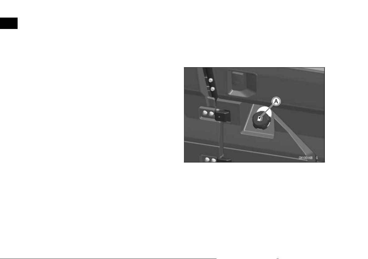
Filling the Fuel tank
The fuel tank is mounted under the right side of
the seat. Use only fresh diesel fuel with the
recommended cetane number from an uncontaminated source to ensure proper running of your vehicle.
Avoid filling the tank in the rain or where heavy
dust is blowing so that the fuel does not get contaminated.
A. Fuel Tank Cap
Never fill the tank completely to the top. After refueling, make sure the fuel tank cap is closed securely.
Page 92
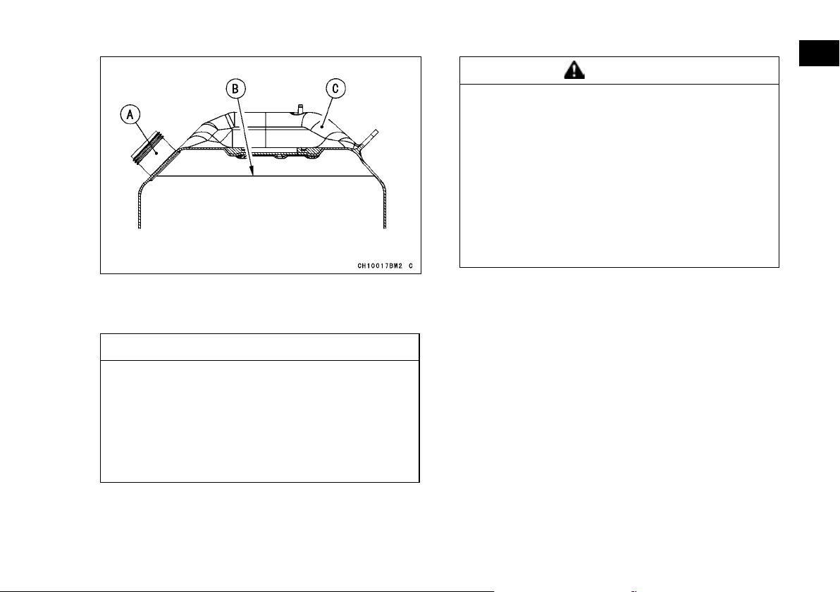
A. Filler Neck
B. Fuel Top Level (Bottom of Filler Neck)
C. Fuel Tank
NOTICE
Always clean dirt/mud/debris/water from the
fuel tank cap and surrounding area prior to
filling the tank to prevent dirt/mud/debris/water from entering the fuel tank. Accumulation of moisture or sediment in the fuel
system can restrict the flow of fuel and cause
fuel system and/or engine damage.
GENERAL INFORMATION 91
WARNING
Diesel fuel is extremely flammable and can
ignite under certain conditions. To avoid the
potential for burns or other injuries when refueling, turn the main switch key off. Do not
smoke. Make sure the area is well ventilated
and free from any source of flame or sparks;
this includes any appliance with a pilot light.
Never fill the tank completely to the top. After
refueling, make sur e the fuel tank cap is
closed securely. If diesel fuel is spilled on the
fuel tank, wipe it off immediately.
Page 93
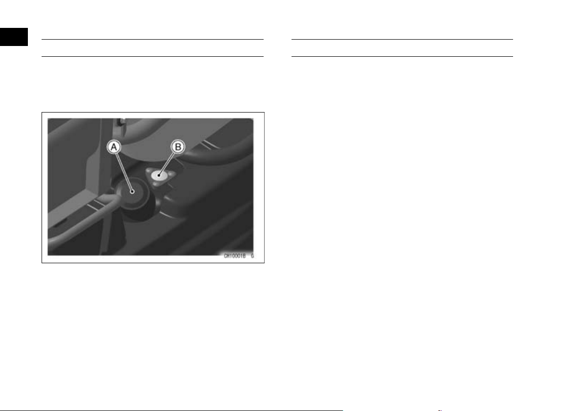
92 GENERAL INFORMATION
Fuel Gauge (KAF400A/B)
The fuel gauge on the fuel tank shows the amount
of fuel in the fuel tank.
When the red indicator needle comes near the “E”
(Empty) mark, refuel at the earliest opportunity.
A. Filling Cap
B. Fuel Gauge
Glove Compartment/Tool Kit
(KAF400A/B)
A glove compartment is provided at the right end
of the dashboard. Store only light items to avoid
damage to the inside of the compartment. Release
the plug in the bottom of the glove compartment to
remove any water that may have entered. Do not
put items which must not get wet or dirty in it.
(KAF1000B/E)
A glove compartment is provided at the right side
of the dashboard. Store only light items to avoid
damage to the inside of the compartment. Do not
store items which must not get wet or dirty.
The tool kit is located at the inside of the glove
compartment.
Page 94
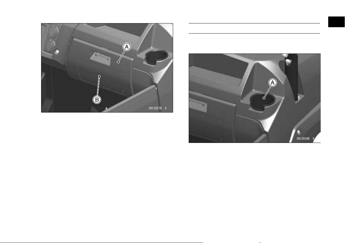
A. Glove Compartment
B. Tool Kit
GENERAL INFORMATION 93
Cupholders (KAF1000B/E)
Cupholders are provided at the left and right sides
of the dashboard.
A. Cupholder (Both Sides)
Page 95
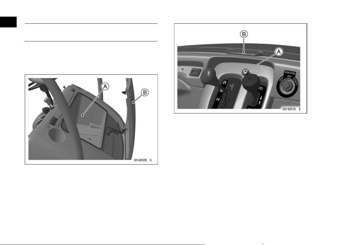
94 GENERAL INFORMATION
Front Cargo Compartment (KAF400A/B)
The front cargo compartment is located under the
front cargo hood. Store only light-weight items in it
to avoid damage to the inside of the compartment.
Do not put items which must not get wet or dirty in it.
A. Front Cargo Compartment
B. Hood
A. Latch Release Button
B. Hood
Hood Closing
While lifting the latch lever at the front of the cargo
hood, push and close the cargo hood.
Hood Opening
Pull the hood latch release button and raise the
hood until it locks.
Page 96
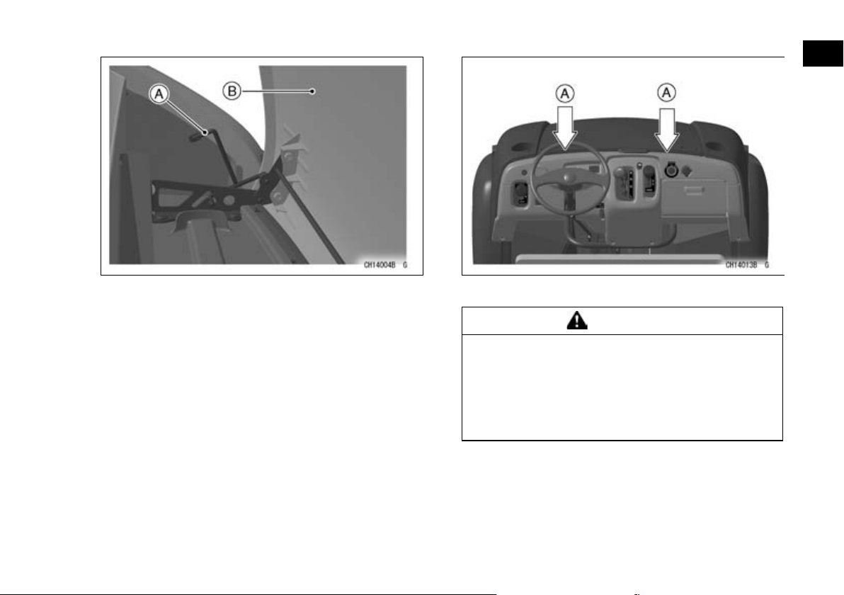
GENERAL INFORMATION 95
A. Latch Lever
B. Hood
After the hood is closed, push the two parts of the
•
hood to ensure the hood is latc hed.
A. Push here.
WARNING
An open front cargo hood can distract or impair visibility of the operator, causing loss of
vehicle control and potential serious injury or
death.
Latch the hood securely before operating the
vehicle.
Page 97
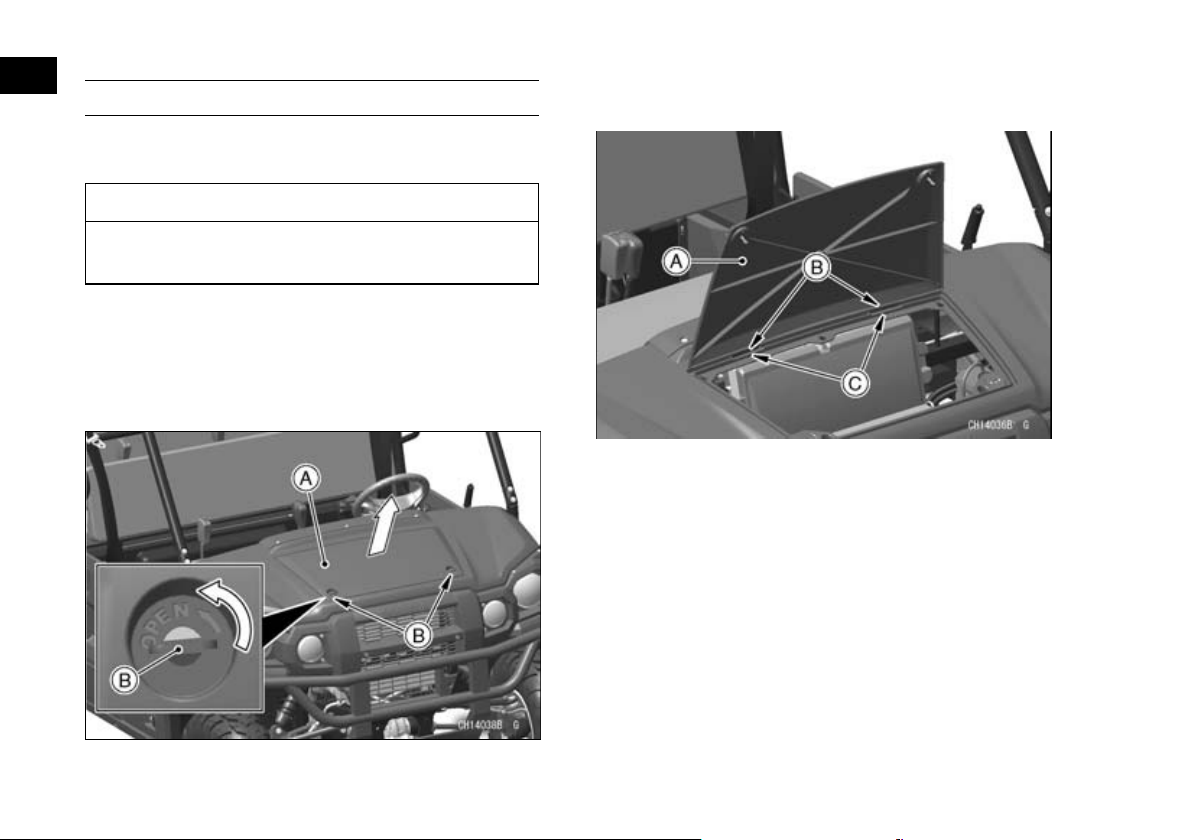
96 GENERAL INFORMATION
Front Access Cover (KAF1000B/E)
The front access cover can be removed for maintenance such as a coolant level inspection.
NOTICE
Do not store items under the front access
cover. This area is not designed for storage.
Cover Opening
Turn the knobs counterclockwise 90° to release
•
the locks.
Pull the front of the front access cover up and
•
open the cover.
Pull the front access cover forward to disengage
•
the tabs from the slits of the front hood.
A. Front Access Cover
B. Tabs
C. Slits
Cover Closing
Insert the tabs on the front access cover to the
•
slits of the front hood.
Lower the front access cover and turn the knobs
•
clockwise until they stop to lock the front access
cover.
A. Front Access Cover
B. Knobs
Page 98
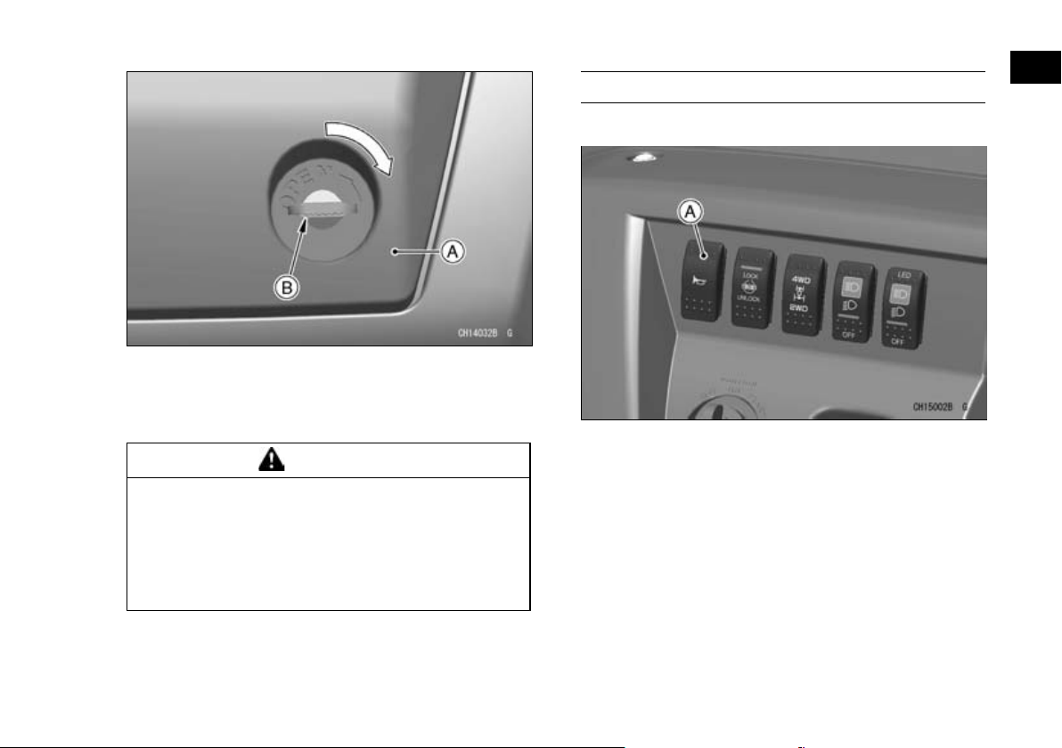
A. Front Access Cover
B. Knob (Both Sides)
Pull up the front ends of the front access cover to
•
make su re the cover is locked securely.
WARNING
An open front access cover can distract or
impair visibility of the operator, causing loss
of vehicle control and potential serious injury
or death.
Lock the front access cover securely before
operating the vehicle.
GENERAL INFORMATION 97
Horn Switch (KAF1000B/E)
Push the horn switch to sound the horn.
A. Horn Switch
Page 99
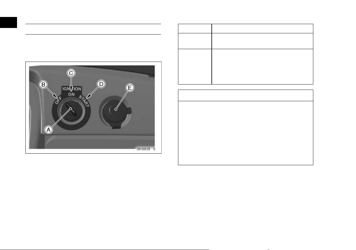
98 GENERAL INFORMATION
Ignition Switch (KAF400A/B)
This is a three-position, key-operated switch. The
key can be removed from the switch only when it is
in the “OFF” position.
A. Ignition Switch
B. “OFF” position
C. “ON” position
D. “START” position
E. Accessory Connector
OFF Engine off. All electrical circuits off.
ON
START
All electrical equipment can be used.
Hour meter works.
Electric starter is engaged by holding
ignition s witch key in this pos ition, only when gear shift lever is in “N” (neutral) position. Upon release, key will
return to “ON” position.
NOTICE
Do not operate the starter continuously for
more than 5 seconds, or the starter will overheat and the battery power will drop temporarily. Wait 15 seconds between each operation
of the starter to let it cool and for the battery
to recover power.
Do not turn the ignition switch key to the
“START” position with the engine running, or
damage to the starter can result.
NOTE
The vehicle is equipped with a starter lockout
○
switch. This switch prevents the electric starter
from operating when the gear shift lever is in the
“H” (High) and “L” (Low) for KAF400A or “F” (Forward) for KAF400B or “R” (Reverse) position.
Blank keys are available at your Kawasaki dealer.
Ask your dealer to make any additional spare keys
Page 100
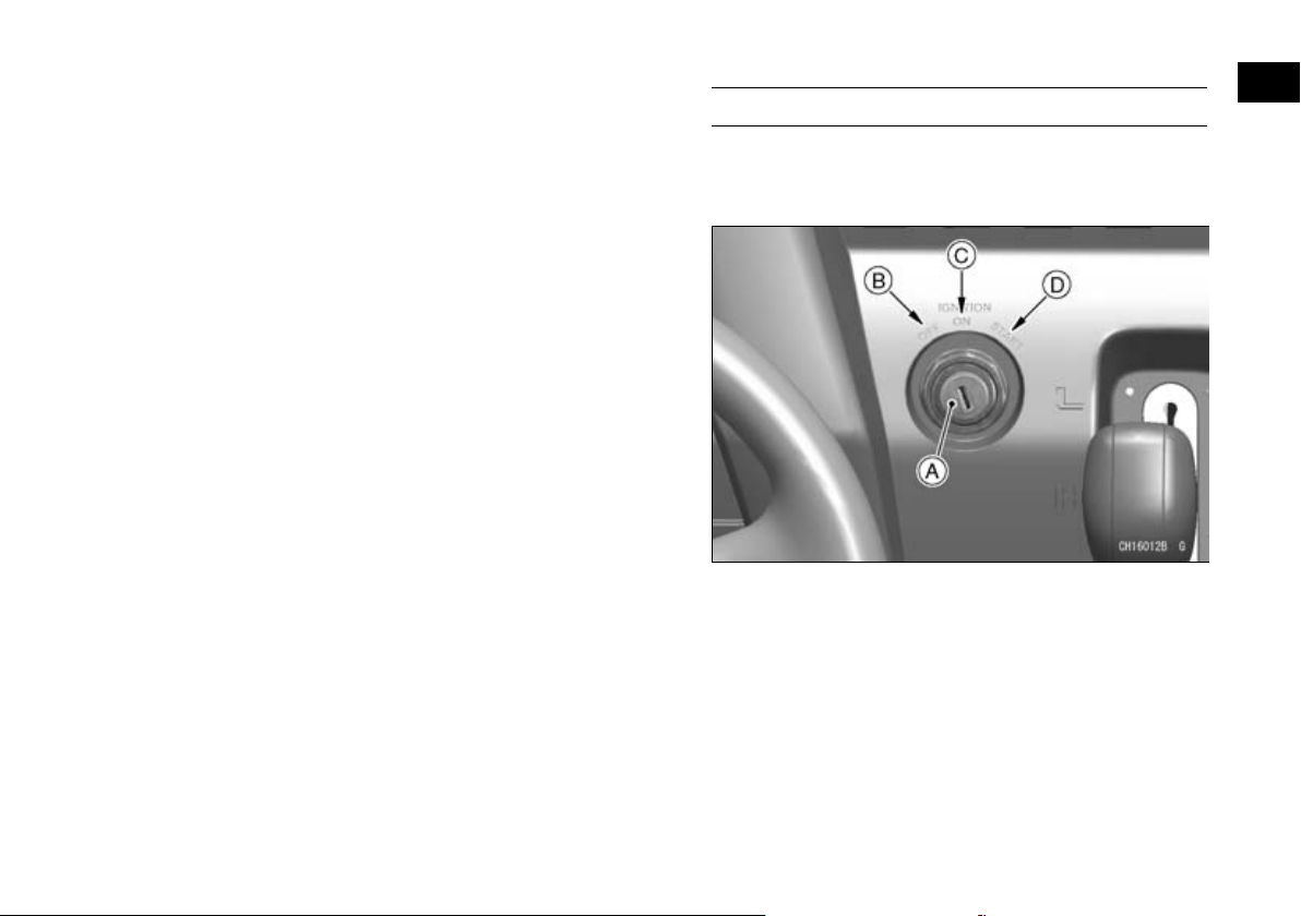
GENERAL INFORMATION 99
you need, using your original key as a master or using the key code on the tag with your keys.
Main Switch (KAF1000B/E)
This is a three-position, key-operated switch. The
key can be removed from the switch only when it is
in the “OFF” position.
A. Main Switch
B. “OFF” Position
C. “ON” Position
D. “START” Position
 Loading...