

Kawasaki J300, J300 ABS, J300 2017, SC300CH 2017 Service Manual

J300
J300 ABS


Quick Reference Guide
General Information 1 j
Periodic Maintenance 2 j
Fuel System (DFI) 3 j
Cooling System 4 j
Engine Top End 5 j
Converter System 6 j
Engine Lubrication System 7 j
Engine Removal/Installation 8 j
This quick reference guide will assist
you in locating a desired topic or procedure.
•Bend the pages back to match the
black tab of the desired chapter number with the black tab on the edge at
each table of contents page.
•Refer to the sectional table of contents
for the exact pages to locate the specific topic required.
Crankcase/Crankshaft 9 j
Wheels/Tires 10 j
Final Drive 11 j
Brakes 12 j
Suspension 13 j
Steering 14 j
Frame 15 j
Electrical System 16 j
Appendix 17 j


J300
J300 ABS
Motorcycle
Service Manual
All rights reserved. No parts of this publication may be reproduced, stored in a retrieval system, or
transmitted in any form or by any means, electronic mechanical photocopying, recording or otherwise,
without the prior written permission of Quality Assurance Division/Motorcycle & Engine Company/Kawasaki
Heavy Industries, Ltd., Japan.
No liability can be accepted for any inaccuracies or omissions in this publication, although every possible
care has been taken to make it as complete and accurate as possible.
The right is reserved to make changes at any time without prior notice and without incurring an obligation
to make such changes to products manufactured previously. See your Motorcycle dealer for the latest
information on product improvements incorporated after this publication.
All information contained in this publication is based on the latest product information available at the time
of publication. Illustrations and photographs in this publication are intended for reference use only and may
not depict actual model component parts.
© 2013 Kawasaki Heavy Industries, Ltd. 2nd Edition (1) : Jul. 10, 2014

LIST OF ABBREVIATIONS
A ampere(s) kg (mass)
ABDC after bottom dead center kgf (force)
AC alternating current km/h kilometers per hour
Ah ampere hour L liter(s)
ATDC after top dead center lb pound(s)
BBDC before bottom dead center
BDC bottom dead center min minute(s)
BTDC before top dead center N newton(s)
°C degree(s) Celsius oz ounce(s)
CDI capacitive discharge ignition Pa pascal(s)
cmHg centimeters of mercury PS horsepower
cu in.
DC direct current qt quart(s)
EMI Electro-Magnetic Interference r revolution
F farad(s) r/min, rpm revolution(s) per minute
°F degree(s) Fahrenheit s second(s)
ft foot, feet SOHC single overhead camshaft
g
gal gallon(s) TIR total indicator
h hour(s) V volt(s)
HP horsepower(s) W watt(s)
in. inch(es) ohm(s)
ISC Idle Speed Control
cubic inch(es)
gram(s) (mass) TDC
m
psi
meter(s)
pound(s) per square inch
top dead center
reading
Foreword
This manual is designed primarily for use by
trained mechanics in a properly equipped shop.
However, it contains enough detail and basic information to make it useful to the owner who desires to perform his own basic maintenance and
repair work. A basic knowledge of mechanics,
the proper use of tools, and workshop procedures must be understood in order to carry out
maintenance and repair satisfactorily. Whenever the owner has insufficient experience or
doubts his ability to do the work, all adjustments, maintenance, and repair should be carried out only by qualified mechanics.
In order to perform the work efficiently and
to avoid costly mistakes, read the text, thoroughly familiarize yourself with the procedures
before starting work, and then do the work carefully in a clean area. Whenever special tools or
equipment are specified, do not use makeshift
tools or equipment. Precision measurements
can only be made if the proper instruments are
used, and the use of substitute tools may adversely affect safe operation.
For the duration of the warranty period,
we recommend that all repairs and scheduled
maintenance be performed in accordance with
this service manual. Any owner maintenance or
repair procedure not performed in accordance
with this manual may void the warranty.
To get the longest life out of your vehicle.
Follow the Periodic Maintenance Chart in the
•
Service Manual.
Be alert for problems and non-scheduled
•
maintenance.
Use proper tools and genuine Kawasaki Mo-
•
torcycle parts. Special tools, gauges, and
testers that are necessary when servicing
Kawasaki motorcycles are introduced by the
Service Manual. Genuine parts provided as
spare parts are listed in the Parts Catalog.
Follow the procedures in this manual care-
•
fully. Don’t take shortcuts.
Remember to keep complete records of main-
•
tenance and repair with dates and any new
parts installed.
How to Use This Manual
In this manual, the product is divided into
its major systems and these systems make up
the manual’s chapters. The Quick Reference
Guide shows you all of the product’s system
and assists in locating their chapters. Each
chapter in turn has its own comprehensive Table of Contents.
For example, if you want ignition coil information, use the Quick Reference Guide to locate
the Electrical System chapter. Then, use the
Table of Contents on the first page of the chapter to find the Ignition Coil section.
Whenever you see symbols, heed their instructions! Always follow safe operating and
maintenance practices.
DANGER
DANGER indicates a hazardous situa-
tion which, if not avoided, will result in
death or serious injury.
WARNING
WARNING indicates a hazardous situa-
tion which, if not avoided, could result
in death or serious injury.
NOTICE
NOTICE is used to address practices not
related to personal injury.
This manual contains four more symbols
which will help you distinguish different types
of information.
NOTE
NOTE indicates information that may help
○
or g uide you in the operation or service of
the vehicle.
Indicates a procedural step or work to be
•
done.
Indicates a procedural sub-step or how to do
the work of the procedural step it follows. It
also precedes the text of a NOTE.
Indicates a conditional step or what action to
take based on the results of the test or inspec-
tion in the procedural step or sub-step it fol-
lows.
In most chapters an exploded view illustration
of the system components follows the Table of
Contents. In these illustrations you will find the
instructions indicating which parts require specified tightening torque, oil, grease or a locking
agent during assembly.


GENERAL INFORMATION 1-1
General Information
Table of Contents
Before Servicing ..................................................................................................................... 1-2
Model Identification................................................................................................................. 1-7
General Specifications............................................................................................................ 1-9
Unit Conversion Table ............................................................................................................ 1-11
1
1-2 GENERAL INFORMATION
Before Servicing
Before starting to perform an inspection service or carry out a disassembly and reassembly operation on a motorcycle, read the precautions given below. To facilitate actual operations, notes, illustrations, photographs, cautions, and detailed descriptions have been included in each chapter wherever
necessary. This section explains the items that require particular attention during the removal and
reinstallation or disassembly and reassembly of general parts.
Especially note the following.
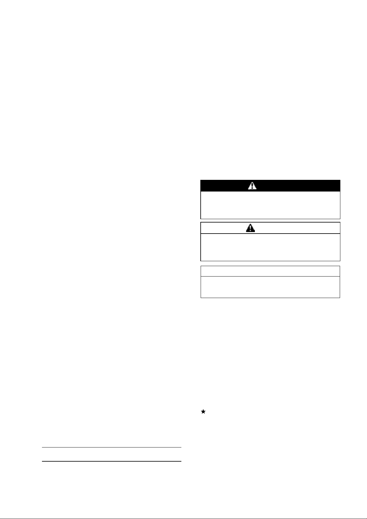
Battery Ground
Before completing any service on the motorcycle, disconnect the battery cables from the battery to prevent the engine from accidentally turning over. Disconnect the ground
cable (–) first and then the positive (+). When completed
with the service, first connect the positive (+) cable to the
positive (+) terminal of the battery then the negative (–) cable to the negative terminal.
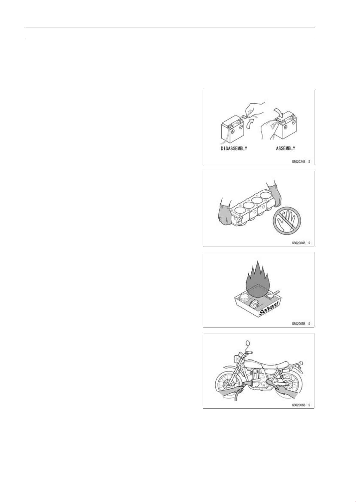
Edges of Parts
Lift large or heavy parts wearing gloves to prevent injury
from possible sharp edges on the parts.
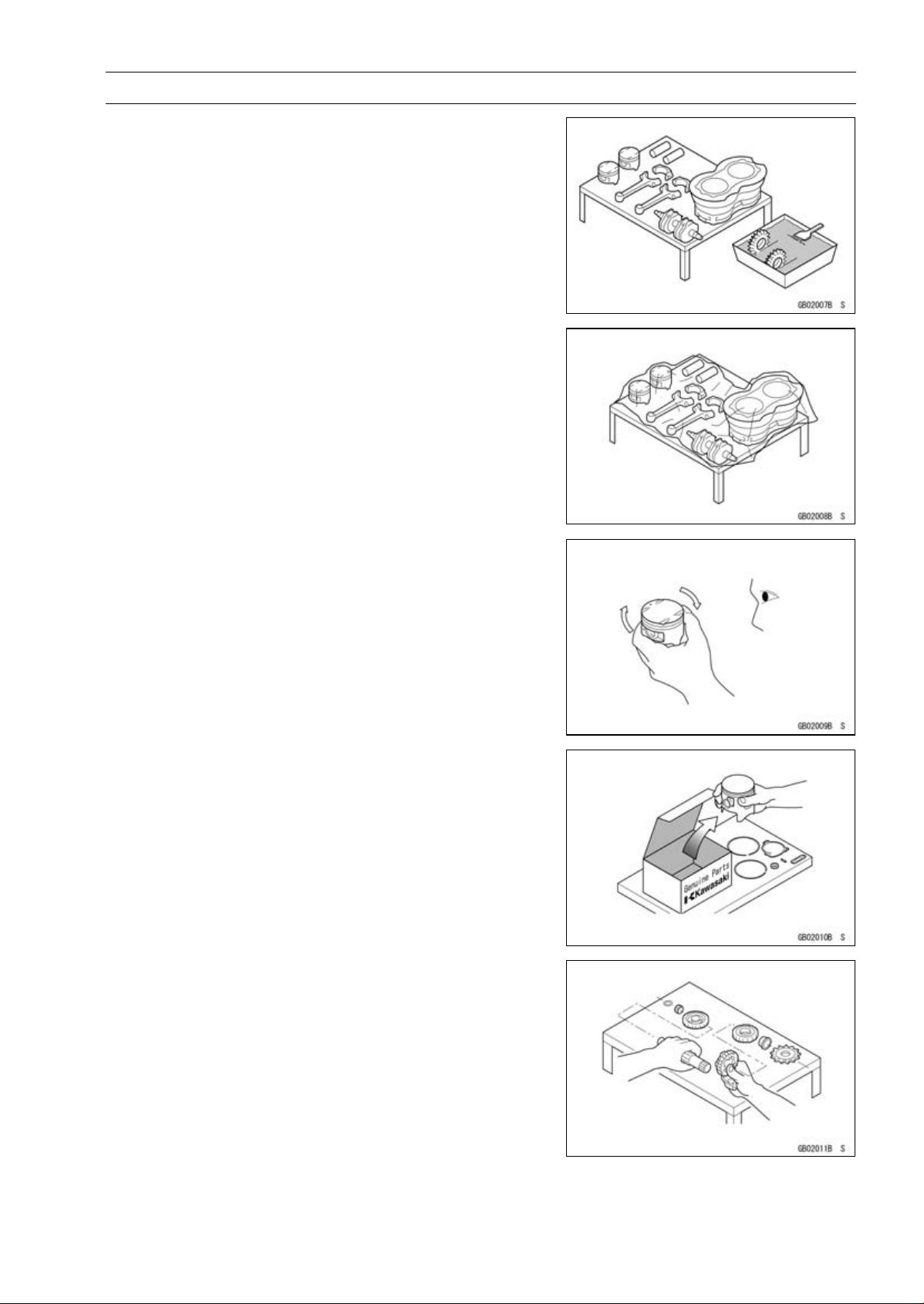
Solvent
Use a high flash-point solvent when cleaning parts. High
flash-point solvent should be used according to directions
of the solvent manufacturer.
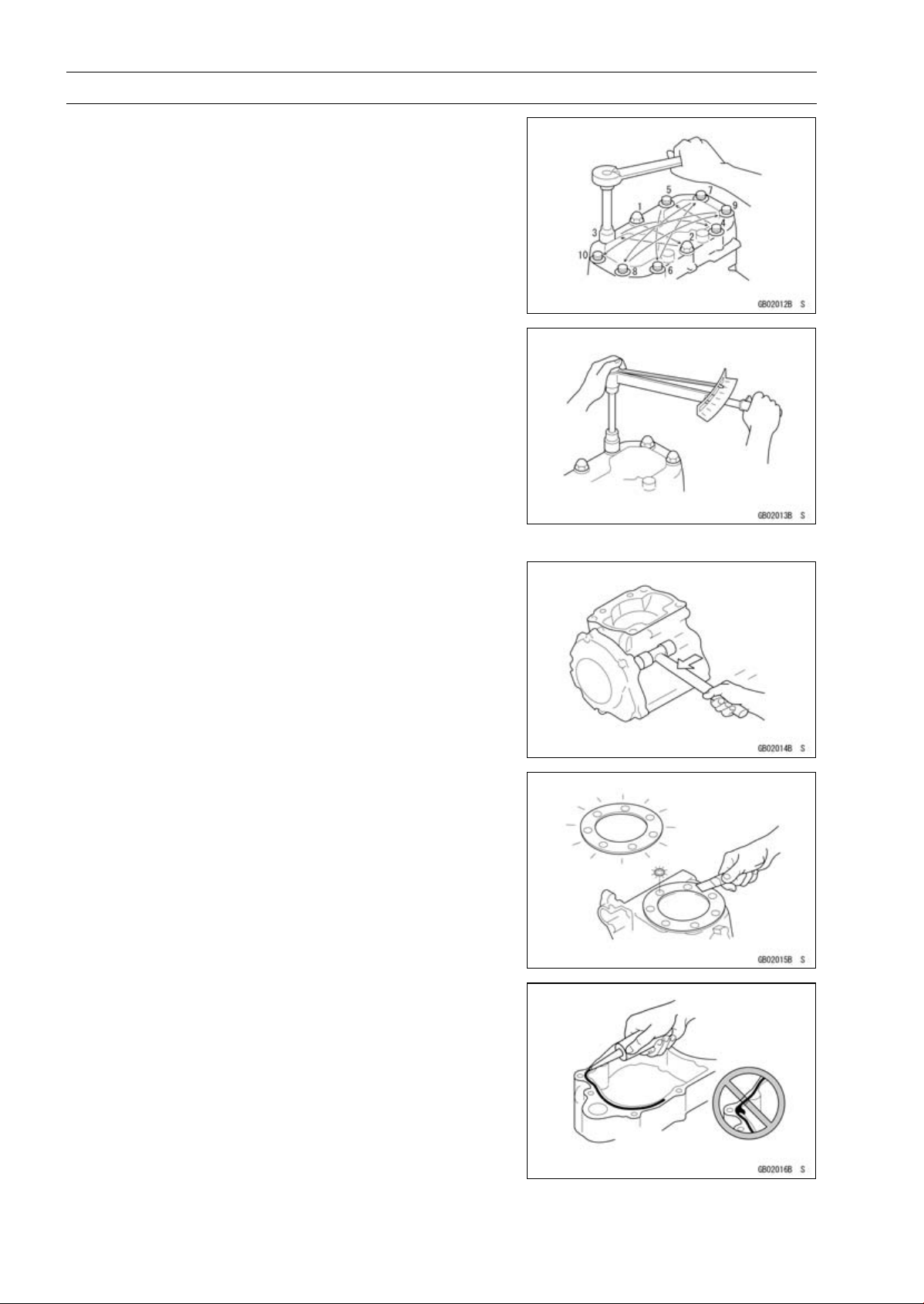
Cleaning Vehicle before Disassembly
Clean the vehicle thoroughly before disassembly. Dirt or
other foreign materials entering into sealed areas during vehicle disassembly can cause excessive wear and decrease
performance of the vehicle.
Before Servicing
Arrangement and Cleaning of Removed Parts
Disassembled parts are easy to confuse. Arrange the
parts according to the order the parts were disassembled
and clean the parts in order prior to assembly.
Storage of Remov ed Parts
After all the parts including subassembly parts have been
cleaned, store the parts in a clean area. Put a clean cloth
or plastic sheet over the parts to protect from any foreign
materials that may collect before re-assembly.
GENERAL INFORMATION 1-3
Inspection
Reuse of worn or damaged parts may lead to serious accident. Visually inspect removed parts for corrosion, discoloration, or other damage. Refer to the appropriate sections
of this manual for service limits on individual parts. Replace
the parts if any damage has been found or if the part is beyond its service limit.
Replacement Parts
Replacement Parts must be KAWASAKI genuine or
recommended by KAWASAKI. Gaskets, O-rings, oil seals,
grease seals, circlips, cotter pins or self-locking nuts must
be replaced with new ones whenever disassembled.
Assembly Order
In most cases assembly order is the reverse of disassembly, however, if assembly order is provided in this Service
Manual, follow the procedures given.
1-4 GENERAL INFORMATION
Before Servicing
Tightening Sequence
Generally, when installing a part with several bolts, nuts,
or screws, start them all in their holes and tighten them to
a snug fit. Then tighten them according to the specified sequence to prevent case warpage or deformation which can
lead to malfunction. Conversely when loosening the bolts,
nuts, or screws, first loosen all of them by about a quarter turn and then remove them. If the specified tightening
sequence is not indicated, tighten the fasteners alternating
diagonally.
Tightening Torque
Incorrect torque applied to a bolt, nut, or screw may
lead to serious damage. Tighten fasteners to the specified
torque using a good quality torque wrench. Often, the
tightening sequence is followed twice-initial tightening and
final tightening with torque wrench.
All of the tightening torque values are for use with dry,
solvent - cleaned threads unless otherwise indicated. If a
fastener which should have dry, clean threads gets contaminated with lubricant, etc., applying even the specified torque
could damage it.
Force
Use common sense during disassembly and assembly,
excessive force can cause expensive or hard to repair damage. When necessary, remove screws that have a non
-permanent locking agent applied using an impact driver.
Use a plastic-faced mallet whenever tapping is necessary.
Gasket, O-ring
Hardening, shrinkage, or damage of both gaskets and
O-rings after disassembly can reduce sealing performance.
Remove old gaskets and clean the sealing surfaces thoroughly so that no gasket material or other material remains.
Install the new gaskets and replace the used O-rings when
re-assembling.
Liquid Gasket, Non-permanent Locking Agent
For applications that require Liquid Gasket or a
Non-permanent Locking Agent, c lean the surfaces so
that no oil residue remains before applying liquid gasket or
non-permanent locking agent. Do not apply them excessively. Excessive application can clog oil passages and
cause serious damage.
Before Servicing
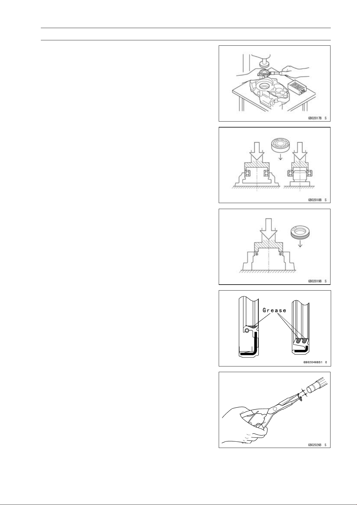
Press
For items such as bearings or oil seals that must be
pressed into place, apply small amount of oil to the contact area. Be sure to maintain proper alignment and use
smooth movements when installing.
Ball Bearing and Needle Bearing
Do not remove pressed ball or needle unless removal is
absolutely necessary. Replace with new ones whenever
removed. Press bearings with the manufacturer and size
marks facing out. Press the bearing into place by putting
pressure on the correct bearing race as shown.
Pressing the incorrect race can cause pressure between
the i nner and outer race and result in bearing damage.
GENERAL INFORMATION 1-5
Oil Seal, Grease Seal
Do not remove pressed oil or grease seals unless removal
is necessary. Replace with new ones whenever removed.
Press new oil seals with manufacture and size marks facing
out. Make sure the seal is aligned properly when installing.
Apply specified grease to the lip of seal before installing
the seal.
Circlips, Cotter Pins
Replace the circlips or cotter pins that were removed with
new ones. Take care not to open the clip excessively when
installing to prevent deformation.
1-6 GENERAL INFORMATION
Before Servicing
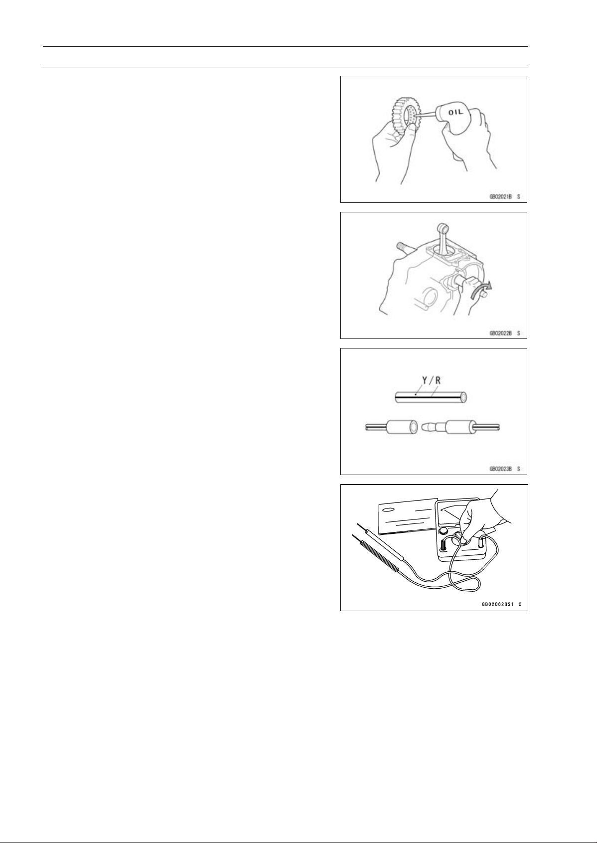
Lubrication
It is important to lubricate rotating or sliding parts during
assembly to minimize wear during initial operation. Lubrication points are called out throughout this manual, apply
the specific oil or grease as specified.
Direction of Engine Rotation
When rotating the crankshaft by hand, the free play
amount of rotating direction will affect the adjustment. Rotate the crankshaft to positive direction (clockwise viewed
from output side).
Electrical Leads
A two-color lead is identified first by the primary color and
then the stripe color. Unless instructed otherwise, electrical
leads must be connected to those of the same color.
Instrument
Use a meter that has enough accuracy for an accurate
measurement. Read the manufacture’s instructions thoroughly before using the meter. Incorrect values may lead
to improper adjustments.
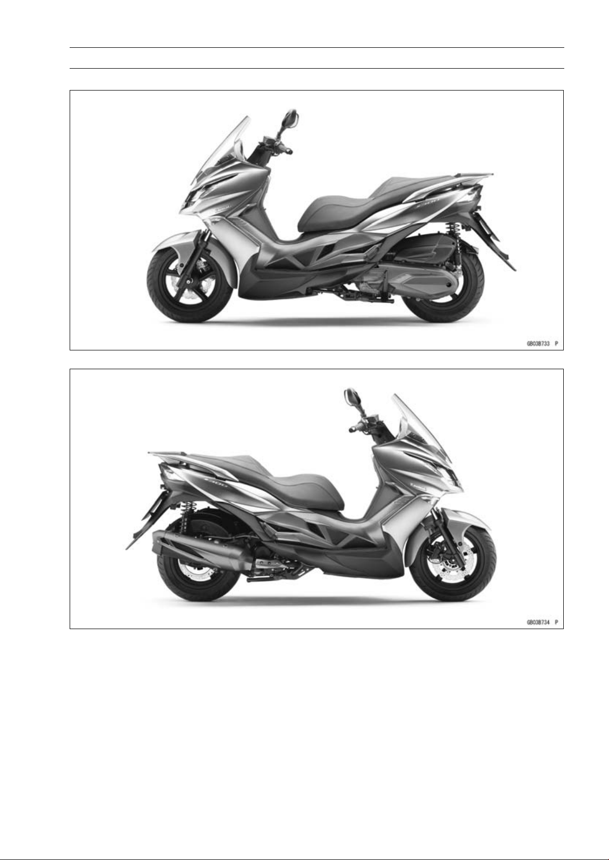
Model Identification
SC300AE Left Side View
GENERAL INFORMATION 1-7
SC300AE Right Side View
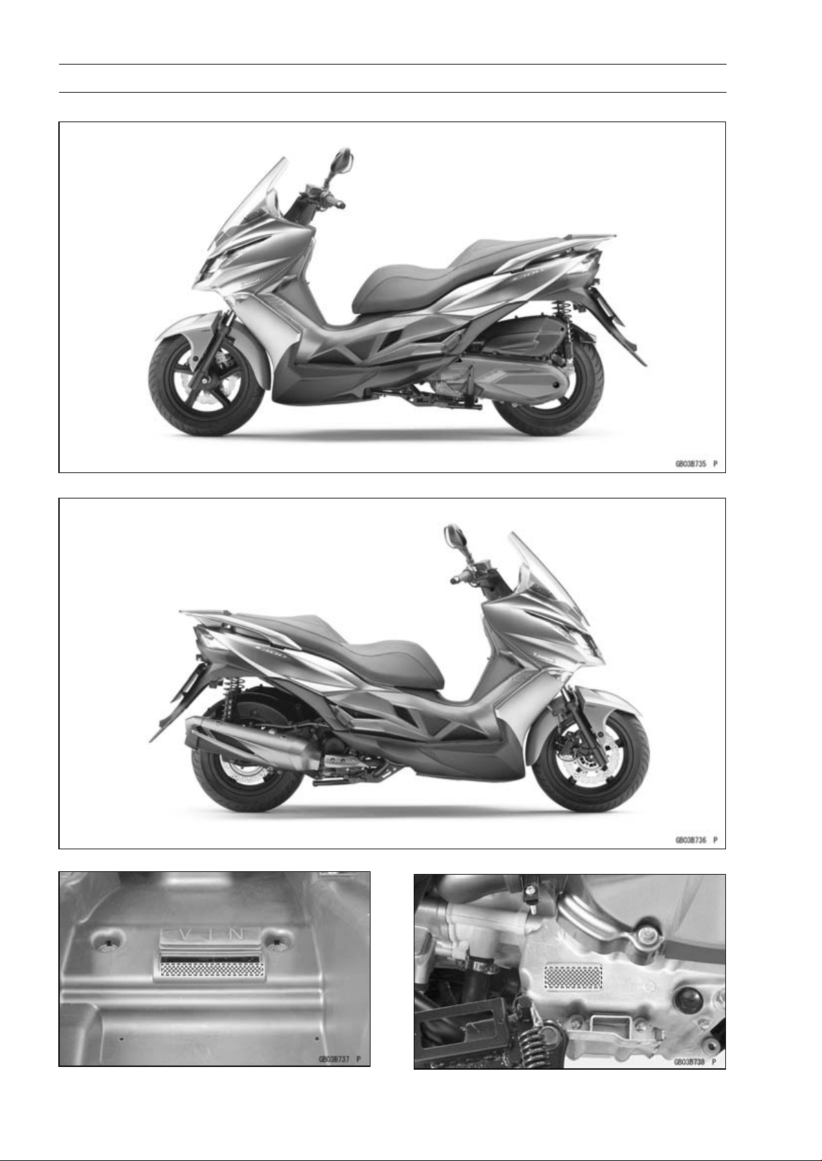
1-8 GENERAL INFORMATION
Model Identification
SC300BE Left S ide View
SC300BE Right Side View
Frame Number Engine Number

GENERAL INFORMATION 1-9
General Specifications
Items SC300AE ∼ AF/BE ∼ BF
Dimensions
Overall Length 2 235 mm (87.99 in.)
Overall Width 775 mm (30.51 in.)
Overall Height 1 260 mm (49.61 in.)
Wheelbase 1 555 mm (61.22 in.)
Road Clearance 145 mm (5.71 in.)
Seat Height 775 mm (30.5 in.)
Curb Mass: 191 kg (421 lb)
Front
Rear 113kg(249lb)
Fuel Tank Capacity 13 L (3.4 US gal)
Performance
Minimum Turning Radius
Engine
Type 4-stroke, SOHC, single cylinder
Cooling System
Bore and Stroke 72.7 × 72.0 mm (2.86 × 2.83 in.)
Displacement 299 cm³ (18.2 cu in.)
Compression Ratio 10.8:1
Maximum Horsepower 20.3 kW (28 PS) @7 750 r/min (rpm)
Maximum Torque 28.7 N·m (2.9 kgf·m, 21 ft·lb) @6 250 r/min (rpm)
Fuel System: FI (Fuel Injection) KEIHIN 34 × 1
Minimum Octane Rating:
Research Octane
Number (RON)
Starting System
Ignition System ECU control (full transistor)
Timing Advance Electronically advanced
Ignition Timing
Spark Plug NGK CR7E
Valve Timing:
Intake:
Open 9° (BTDC)
Close 37° (ABDC)
Duration 226°
Exhaust:
Open 39° (BTDC)
Close 10° (ATDC)
Duration
Lubrication System Forced lubrication (wet sump)
78 kg (172 lb)
2.6 m (8.5 ft)
Liquid-cooled
91
Electric starter
10.0° BTDC @1 600 r/min (rpm) to 30.0° BTDC @7 750 r/min
(rpm)
229°

1-10 GENERAL INFORMATION
General Specifications
Items SC300AE ∼ AF/BE ∼ BF
Engine Oil:
Type
Viscosity SAE 5W-50
Capacity 1.5L(1.6USqt)
Drive Train
Driving System V-Matic continuously variable
Primary Reduction Ratio 2.220 ∼ 0.790
Final Reduction Ratio 7.222
Over Drive Ratio 16.030 ∼ 5.700
Clutch Type Automatic, centrifugal
Frame
Type Tubular diamond
Caster (Rake Angle) 28°
Trail 113 mm (4.45 in.)
Front Tire:
Type MAXXIS, i PRO, Tubeless
Size 120/80-14 M/C 58S
Rear Tire:
Type MAXXIS, PRO, Tubeless
Size 150/70-13 M/C 64S
Rim Size:
Front J14×3.0
Rear J13×4.0
Front Suspension:
Type Telescopic fork
Wheel Travel 110 mm (4.33 in.)
Rear Suspension:
Type
Wheel Travel 100 mm (3.94 in.)
Brake Type:
Front
Rear
Electrical Equipment
Battery
Headlight:
Type Semi-sealed beam
Bulb:
High 12 V 35 W × 2
Low 12 V 35 W × 2
Tail/Brake Light
Alternator:
Type Three-phase AC
Maximum Output 25.0 A/14 V @10 000 r/min (rpm)
API SJ, SL or SM with JASO MA, MA1 or MA2
Swingarm
Single disc
Single disc
12V10Ah(10HR)
LED
Specifications are subject to change without notice, and may not apply to every country.
Unit Conversion Table
GENERAL INFORMATION 1-11
Prefixes for Units:
Prefix Symbol Power
mega M × 1 000 000
kilo k ×1000
centi c ×0.01
milli m × 0.001
micro µ × 0.000001
Units of Mass:
kg ×2.205=lb
g × 0.03527 = oz
Units of Volume:
L × 0.2642 = gal (US)
L × 0.2200 = gal (IMP)
L × 1.057 =
L × 0.8799 =
L × 2.113 = pint (US)
L × 1.816 = pint (IMP)
mL × 0.03381 = oz (US)
mL × 0.02816 = oz (IMP)
mL × 0.06102 = c u in.
qt (US)
qt (IMP)
Units of Length:
km × 0.6214 = mile
m × 3.281 = ft
mm × 0.03937 = in.
Units of Torque:
N·m × 0.1020 = kgf·m
N·m × 0.7376 = ft·lb
N·m × 8.851 = in·lb
kgf·m × 9.807 = N·m
kgf·m × 7.233 = ft·lb
kgf·m × 86.80 = in·lb
Units of Pressure:
kPa × 0.01020 = kgf/cm²
kPa × 0.1450 = psi
kPa × 0.7501 = cmHg
kgf/cm² × 98.07 = kPa
kgf/cm² × 14.22 = psi
cmHg×1.333=kPa
Units of Speed:
km/h
× 0.6214 = mph
Units of Force:
N × 0.1020 = kg
N × 0.2248 = lb
kg ×9.807=N
kg ×2.205=lb
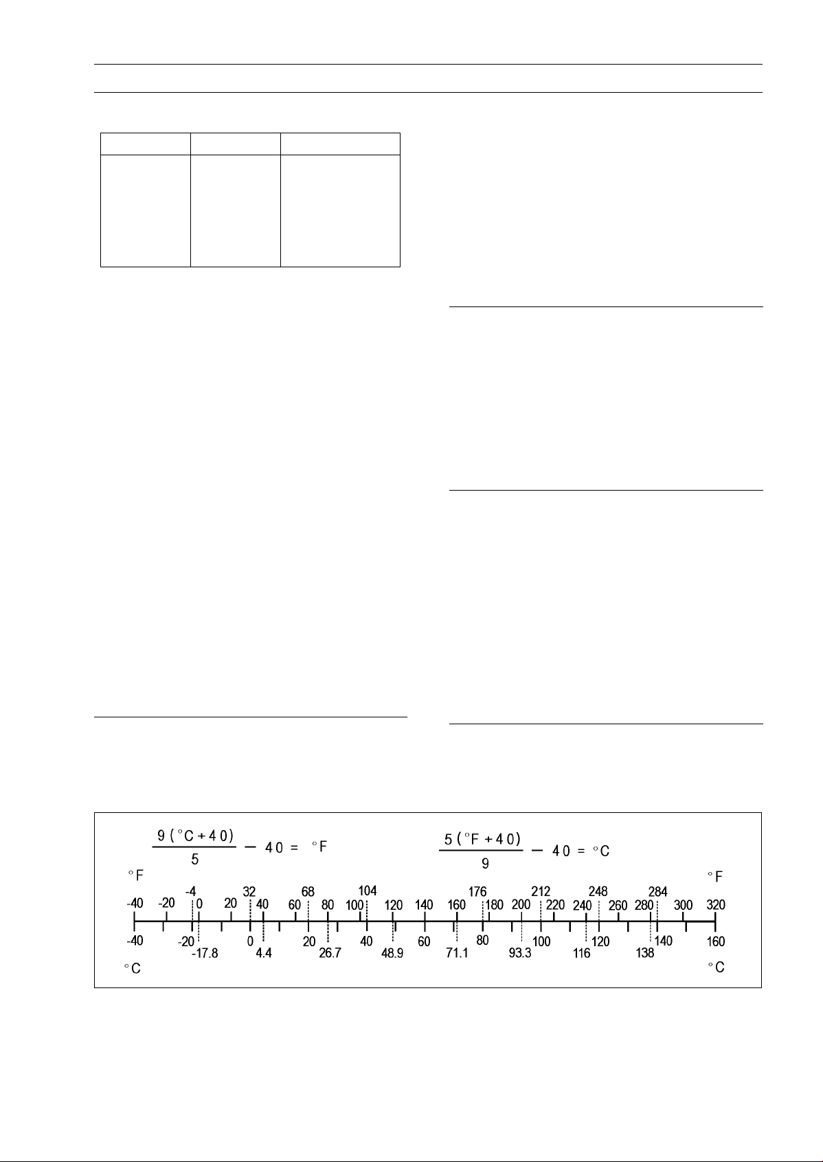
Units of Temperature:
Units of Power:
kW ×1.360=PS
kW ×1.341=HP
PS
PS × 0.9863 = HP
× 0.7355 = kW


PERIODIC MAINTENANCE 2-1
Periodic Maintenance
Table of Contents
Periodic Maintenance Chart .............. 2-2
Torque and Locking Agent................. 2-4
Specifications .................................... 2-8
Special Tools ..................................... 2-10
Periodic Maintenance Procedures..... 2-11
Fuel System (DFI)........................... 2-11
Air Cleaner Element
Replacement............................. 2-11
Idle Speed Inspection .................. 2-12
Idle Speed Adjustment................. 2-12
Throttle Control System
Inspection.................................. 2-12
Fuel System ................................. 2-13
Fuel Hose Replacement .............. 2-14
Cooling System............................... 2-16
Coolant Level Inspection.............. 2-16
Cooling System ............................ 2-16
Coolant Change ........................... 2-16
Engine Top End .............................. 2-19
Valve Clearance Inspection ......... 2-19
Valve Clearance Adjustment........ 2-20
Clutch.............................................. 2-20
Clutch Shoe Wear Inspection ..... 2-20
Engine Lubrication System ............. 2-20
Engine Oil Change....................... 2-20
Oil Service Indicator Light Reset.. 2-22
Oil Filter Replacement ................. 2-22
Oil Screen Inspection................... 2-23
Breather Hose Inspection ............ 2-23
Wheels/Tires................................... 2-23
Air Pressure Inspection................ 2-23
Wheels and Tires ......................... 2-24
Wheel Bearing Damage
Inspection.................................. 2-24
Converter ........................................ 2-25
Drive Belt Wear Inspection .......... 2-25
Drive Belt Replacement ............... 2-25
Final Drive....................................... 2-27
Final Gear Case Oil Change ........ 2-27
Brakes............................................. 2-28
Brake System............................... 2-28
Brake Fluid Level Inspection........ 2-29
Brake Fluid Change ..................... 2-30
Brake Hose Replacement ............ 2-31
Master Cylinder Rubber Parts
Replacement............................. 2-32
Caliper Rubber Parts
Replacement............................. 2-32
Brake Pad Wear Inspection ......... 2-35
Brake Light Switch Operation
Inspection .................................. 2-36
Suspension..................................... 2-36
Suspension System ..................... 2-36
Steering .......................................... 2-37
Steering Play Inspection .............. 2-37
Steering Play Adjustment............. 2-37
Steering Stem Bearing
Lubrication................................. 2-38
Electrical System ............................ 2-39
Lights and Switches Operation
Inspection .................................. 2-39
Headlight Aiming Inspection ........ 2-41
Engine Stop Switch Operation
Inspection .................................. 2-42
Spark Plug Replacement ............. 2-42
Others............................................. 2-43
Chassis Parts Lubrication ........... 2-43
Condition of Bolts, Nuts and
Fasteners Tightness Inspection 2-44
2
2-2 PERIODIC MAINTENANCE
Periodic Maintenance Chart
The scheduled maintenance must be done in accordance with this chart to k eep the motorcycle in
good running condition.
The initial maintenance is vitally important and must not be neglected.
I: Inspection and Clean, Adjust, Lubricate or Replace if necessary
C: Clean
A: Adjust
R: Replace
L: Lubricate
*: Should be serviced by your Kawasaki dealer, unless you have the proper tools, service data
and are technically qualified.
**: In the interest of safety, we recommend these items be serviced only by your Kawasaki dealer.
Kawasaki recommends that your Kawasaki dealer road test your scooter after each periodic
maintenance service is completed.
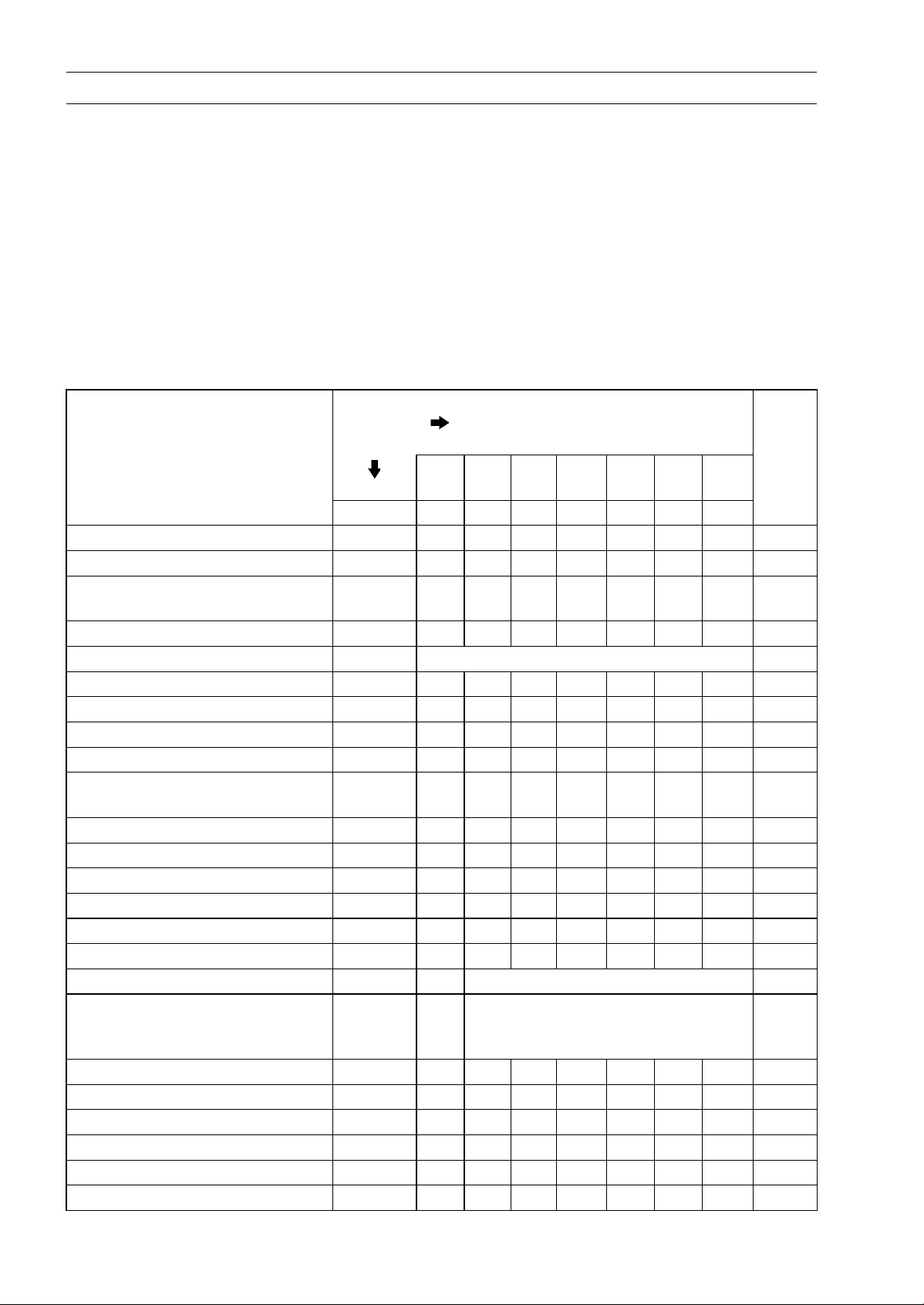
FREQUENCY
ITEM MONTH 1 6 12 18 24 30 36
* Air cleaner element R R R R R R 2-11
* Idle speed I I I 2-12
Throttle control system (play,
*
smooth return, no drag)
* Fuel system I I I 2-13
Fuel hose
**
** Coolant I R I R I R 2-16
* Valve clearance I A I A I A 2-19
** Clutch shoe wear I I I 2-20
Engine oil and oil filter R R R R R R R 2-20
Engine oil screens (both right
*
and left)
Crankcase breather C C C C C C C 2-23
** Wheels/tires I I I I I I 2-23
Drive belt
*
* Transmissi
Brake system I I I I I I 2-28
Brake fluid
Brake hose Replace at every 4 years 2-31
Brake rubber parts
Brake pad wear I I I I I I 2-35
Brake light switch I I I I I I 2-36
Suspension system I I I 2-36
Steering stem bearings I I I I I I 2-38
Electrical system
*
Spark plug I R I R I R 2-42
on oil
Whichever
comes
first
*Odometer Reading
× 1 000 km (× 1 000 mil
1
(0.6)5(3)10(6)15(9)20(12)25(15)30(18)
I I I I I I 2-12
Replace at every 5 years 2-14
C R C R C R 2-23
I I I R I I 2-25
R R R R R R R 2-27
I R I R I R 2-29
Replace at every 48 000 km (30
000 mile) or 4 years (whichever
occurs earlier)
I I I I I I 2-39
e)
Page
See
2-32

Periodic Maintenance Chart
PERIODIC MAINTENANCE 2-3
FREQUENCY
ITEM MONTH 1 6 12 18 24 30 36
Chassis parts L L L 2-43
Condition of bolts, nuts and
*
fasteners
Whichever
comes
first
*Odometer Reading
× 1 000 km (× 1 000 mile)
1
(0.6)5(3)10(6)15(9)20(12)25(15)30(18)
I I I I I I 2-44
See
Page

2-4 PERIODIC MAINTENANCE
Torque and Locking Agent
Tighten all bolts and nuts to the proper torque using an accurate torque wrench. If insufficiently
tightened, a bolt or nut may become damaged, strip an internal thread, or break and then fall out. The
following table lists the tightening torque for the major bolts and nuts, and the parts requiring use of
a non-permanent locking agent or silicone grease etc. All of the values are for use with dry solvent cleaned threads unless otherwise indicated.
When checking the tightening torque of the bolts and nuts, first loosen the bolt or nut by half a turn
and then tighten to specified torque.
Letters used in the “Remarks” column mean:
AL: Tighten the two clamp bolts alternately two times to ensure even tightening torque.
EO: Apply engine oil.
G: Apply grease.
L: Apply a non-permanent locking agent.
Lh: Left-hand Threads
R: Replacement Parts
S: Follow the specified tightening sequence.
Si: Apply silicone grease.
SS: Apply silicone sealant.
Fastener
Fuel System (DFI)
Water Temperature Sensor (ECU) 12 1.2 106 in·lb
Fuel Injector Mounting Bolt 9.8 1.0 87 in·lb
Oxygen Sensor 25 2.5 18
Fuel Pump Mounting Screws 3.4 0.35 30 in·lb
Cooling System
Water Hose Clamp Screws 4.4 0.45 39 in·lb
Thermostat Housing Cover Bolts
Water Pump Cover Bolts 9.8 1.0 87 in·lb
Water Pump Impeller 12 1.2 106 in·lb Lh
Water Temperature Sensor (ECU)
Water Temperature Sensor (Meter) 7.4 0.75 65 in·lb SS
Engine Top End
Upper Camshaft Chain Guide Bolt
Rocker Shaft Stopper Bolt 8.8 0.90 78 in·lb L
Intake Manifold Stud Bolts 8.8 0.90 78 in·lb
Cylinder Head Stud Bolts 8.8 0.90 78 in·lb
Exhaust Pipe Manifold Stud Bolts 8.8 0.90 78 in·lb
Camshaft Sprocket Bolts 12 1.2 106 in·lb L
Cylinder Head Nuts (M10) (First)
Cylinder Head Nuts (M10) (Final) 37 3.8 27 S
Cylinder Head Nuts (M6) 9.8 1.0 87 in·lb S
Cylinder Head Bolts 9.8 1.0 87 in·lb S
Cylinder Bolts 9.8 1.0 87 in·lb S
Camshaft Chain Tensioner Mounting Bolts 12 1.2 106 in·lb
Camshaft Chain Tensioner Cap Bolt
Spark Plug 12 1.2 106 in·lb
Fuel Hose Bracket Bolt 9.8 1.0 87 in·lb
N·m kgf·m ft·lb
7.4 0.75 65 in·lb
12 1.2 106 in·lb
9.8 1.0 87 in·lb
20 2.0 15
4.4 0.45 39 in·lb
Torque
Remarks
S

Torque and Locking Agent
PERIODIC MAINTENANCE 2-5
Fastener
Cylinder Head Cover Bolts
Intake Manifold Mounting Nuts 9.8 1.0 87 in·lb
Valve Adjusting Screw Locknuts 8.8 0.90 78 in·lb
Muffler Body Mounting Bolts 34 3.5 25
Exhaust Pipe Manifold Holder Nuts 20 2.0 15
Converter System
Left Crankcase Cover Bolts
Drive Face Nut 93 9.5 69
Clutch Outer Nut
Clutch Drive Plate Nut
Engine Lubrication System
Oil Screen Plug 9.3 0.95 82 in·lb
Oil Pump Screws 9.8 1.0 87 in·lb
Oil Separator Cover Bolts 9.8 1.0 87 in·lb
Oil Pressure Switch
Engine Oil Drain Bolt
Oil Filter Cap 9.3 0.95 82 in·lb L
Engine Removal/Installation
Engine Hanger Nuts 64 6.5 47 R
Engine Mounting Nut 49 5.0 36 R
Crankcase/Crankshaft
Crankcase Bolts
Engine Stud Bolts 12 1.2 106 in·lb EO
Starter Motor Clutch Bolts 20 2.0 15 L
Wheels/Tires
Front Axle 20 2.0 15
Rear Axle Nut 118 12.0 87.0 R
Sub Frame Bolts
Final Drive
Final Gear Case Cover Bolts
Oil Filler Bolt
Final Gear Case Oil Drain Bolt 9.8 1.0 87 in·lb
Brakes
Front Caliper Mounting Bolts
Front Wheel Rotation Sensor Bolt 12 1.2 106 in·lb
Brake Hose Banjo Bolts 34 3.5 25
Brake Disc Mounting Bolts 34 3.5 25 L
Brake Reservoir Cap Screws 1.6 0.16 14 in·lb
Master Cylinder Clamp Bolts
Brake Lever Pivot Bolt 2.0 0.20 18 in·lb
Brake Lever Pivot Bolt Locknut 9.8 1.0 87 in·lb
Brake Light Switch Screw
Bleed Valves 5.4 0.55 48 in·lb
N·m
9.8 1.0 87 in·lb
9.8 1.0 87 in·lb
54 5.5 40
54 5.5 40
23 2.3 17
25 2.5 18 R
9.8 1.0 87 in·lb
34 3.5 25
20 2.0 15
9.8 1.0 87 in·lb
34 3.5 25 L
12 1.2 106 in·lb
1.0 0.10 8.9 in·lb
Torque
Remarks
kgf·m ft·lb
Si

2-6 PERIODIC MAINTENANCE
Torque and Locking Agent
Fastener
Brake Pad Pin 18 1.8 13 L
Rear Caliper Mounting Bolts 34 3.5 25 L
ABS Hydraulic Unit Mounting Nuts 7.8 0.80 69 in·lb
Suspension
Front Fork Clamp Bolts 26 2.7 19 AL
Front Fork Bottom Allen Bolts 29 3.0 21 L
Upper Rear Shock Absorber Nuts 39 4.0 29 R
Lower Rear Shock Absorber Bolts 39 4.0 29
Sub Frame Bolts
Steering
Steering Stem Nut 20 2.0 15
Steering Stem Lock Nut 62 6.3 46
Handlebar Mounting Nut 44 4.5 32 R
Frame
Grab Rail Mounting Bolts
Electrical System
Ignition Coil Mounting Nuts 12 1.2 106 in·lb
Starter Relay Terminal Nuts 29 3.0 21
Starter Motor Mounting Bolts 9.8 1.0 87 in·lb
Water Temperature Sensor (Meter) 7.4 0.75 65 in·lb SS
Water Temperature Sensor (ECU)
Alternator Rotor Nut 59 6.0 44
Alternator Cover Bolts 9.8 1.0 87 in·lb
Timing Inspection Cap
Alternator Cover Center Cap (SC300AE/BE) 4.4 0.45 39 in·lb
Alternator Cover Center Cap (SC300AF ∼/BF ∼) 9.8 1.0 87 in·lb
Stator Coil Bolts 9.8 1.0 87 in·lb
Crankshaft Sensor Bolts 4.4 0.45 39 in·lb
Starter Motor Clutch Bolts 20 2.0 15 L
Oxygen Sensor
N·m kgf·m ft·lb
34 3.5 25
24 2.4 18
12 1.2 106 in·lb
4.4 0.45 39 in·lb
25 2.5 18
Torque
Remarks

PERIODIC MAINTENANCE 2-7
Torque and Locking Agent
The table below, relating tightening torque to thread diameter, lists the basic torque for the bolts and
nuts. Use this table for only the bolts and nuts which do not require a specific torque value. All of the
values are for use with dry solvent-cleaned threads.
Basic Torque for General Fasteners
Threads Diameter
(mm)
5 3.4 ∼ 4.9 0.35 ∼ 0.50 30 ∼ 43 in·lb
6 5.9 ∼ 7.8 0.60 ∼ 0.80 52 ∼ 69 in·lb
8 14 ∼ 19 1.4 ∼ 1.9 10 ∼ 13.5
10 25 ∼ 34 2.6 ∼ 3.5 19 ∼ 25
12 44 ∼ 61 4.5 ∼ 6.2 33 ∼ 45
14 73 ∼ 98 7.4 ∼ 10.0 54 ∼ 72
16 115 ∼ 155 11.5 ∼ 16.0 83 ∼ 115
18 165 ∼ 225 17.0 ∼ 23.0 125 ∼ 165
20 225 ∼ 325 23.0 ∼ 33.0 165 ∼ 240
N·m kgf·m ft·lb
Torque

2-8 PERIODIC MAINTENANCE
Specifications
Item Standard Service Limit
Fuel System (DFI)
ThrottleGripFreePlay 2 ∼ 6 mm (0.08 ∼ 0.24 in.) –––
Idle Speed 1 600 ±100 r/min (rpm) –––
Air Cleaner Element Wet paper element –––
Cooling System
Coolant:
Type (Recommended) Permanent type of antifreeze
Color Green –––
Mixed Ratio Soft water 50%, coolant 50% –––
Freezing Point –35°C (–31°F) –––
Total Amount 1.5L(1.6USqt) –––
Engine Top End
Valve Clearance:
Exhaust 0.10 mm (0.0039 in.) –––
Intake 0.10 mm (0.0039 in.) –––
Converter
Drive Belt Width 25.2 mm (0.992 in.) 23.7 mm (0.933 in.)
Engine Lubrication System
Engine Oil:
Type API SJ, SL or SM with JASO MA, MA1 or
MA2
Viscosity SAE 5W-50 –––
Capacity 1.3L(1.4USqt) –––
1.5 L (1.6 US qt) (when engine is completely
dry)
Level Between upper and lower level lines (Wait 2
∼ 3 minutes after idling or running)
Wheels/Tires
Tread Depth:
Front ––– 1 mm (0.04 in.)
Rear ––– 1 mm (0.04 in.)
Air Pressure (when Cold):
Front 200 kPa (2.0 kgf/cm², 29 psi) –––
Rear
Final Drive
Final Gear Case Oil:
Viscosity
Capacity 0.23 L (0.24 US qt) at disassembly –––
Brakes
Brake Fluid:
Grade DOT4 –––
Brake Pad Lining Thickness:
Front 5 mm (0.20 in.) 1 mm (0.04 in.)
Rear 5.8 mm (0.23 in.) 1 mm (0.04 in.)
225 kPa (2.25 kgf/cm², 33 psi)
SAE 90
0.21 L (0.22 US qt) at change –––
–––
–––
–––
–––
–––
–––

PERIODIC MAINTENANCE 2-9
Specifications
Item Standard Service Limit
Brake Light Timing:
Front
Rear Pulled ON –––
Electrical System
Spark Plug:
Type NGK CR7E –––
Gap 0.7 ∼ 0.8 mm (0.028 ∼ 0.031 in.)
Pulled ON
–––
–––
2-10 PERIODIC MAINTENANCE
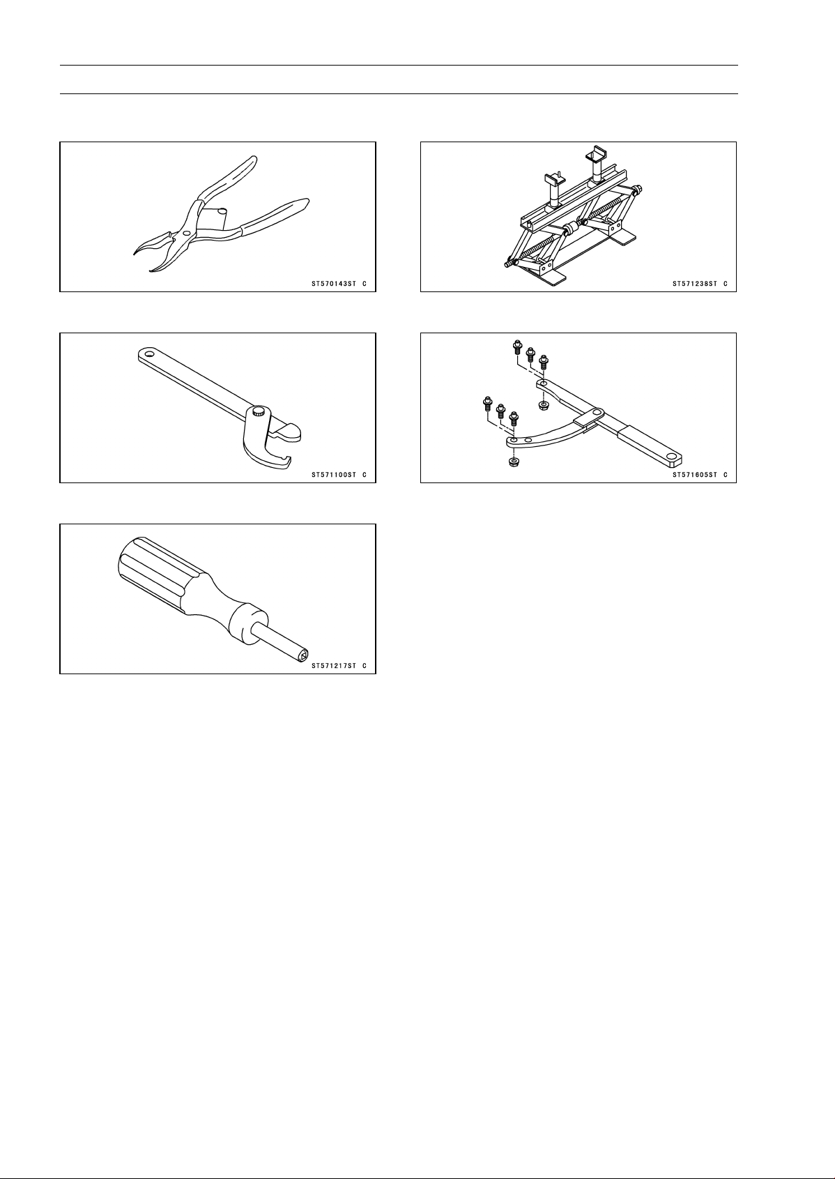
Special Tools
Inside Circlip Pliers:
57001-143
Steering Stem Nut Wrench:
57001-1100
Valve Adjusting Screw Holder:
57001-1217
Jack:
57001-1238
Flywheel & Pulley Holder:
57001-1605
 Loading...