

Page 1
J300
J300 ABS
Page 2

Page 3
Quick Reference Guide
General Information 1 j
Periodic Maintenance 2 j
Fuel System (DFI) 3 j
Cooling System 4 j
Engine Top End 5 j
Converter System 6 j
Engine Lubrication System 7 j
Engine Removal/Installation 8 j
This quick reference guide will assist
you in locating a desired topic or procedure.
•Bend the pages back to match the
black tab of the desired chapter number with the black tab on the edge at
each table of contents page.
•Refer to the sectional table of contents
for the exact pages to locate the specific topic required.
Crankcase/Crankshaft 9 j
Wheels/Tires 10 j
Final Drive 11 j
Brakes 12 j
Suspension 13 j
Steering 14 j
Frame 15 j
Electrical System 16 j
Appendix 17 j
Page 4

Page 5

J300
J300 ABS
Motorcycle
Service Manual
All rights reserved. No parts of this publication may be reproduced, stored in a retrieval system, or
transmitted in any form or by any means, electronic mechanical photocopying, recording or otherwise,
without the prior written permission of Quality Assurance Division/Motorcycle & Engine Company/Kawasaki
Heavy Industries, Ltd., Japan.
No liability can be accepted for any inaccuracies or omissions in this publication, although every possible
care has been taken to make it as complete and accurate as possible.
The right is reserved to make changes at any time without prior notice and without incurring an obligation
to make such changes to products manufactured previously. See your Motorcycle dealer for the latest
information on product improvements incorporated after this publication.
All information contained in this publication is based on the latest product information available at the time
of publication. Illustrations and photographs in this publication are intended for reference use only and may
not depict actual model component parts.
© 2013 Kawasaki Heavy Industries, Ltd. 2nd Edition (1) : Jul. 10, 2014
Page 6

LIST OF ABBREVIATIONS
A ampere(s) kg (mass)
ABDC after bottom dead center kgf (force)
AC alternating current km/h kilometers per hour
Ah ampere hour L liter(s)
ATDC after top dead center lb pound(s)
BBDC before bottom dead center
BDC bottom dead center min minute(s)
BTDC before top dead center N newton(s)
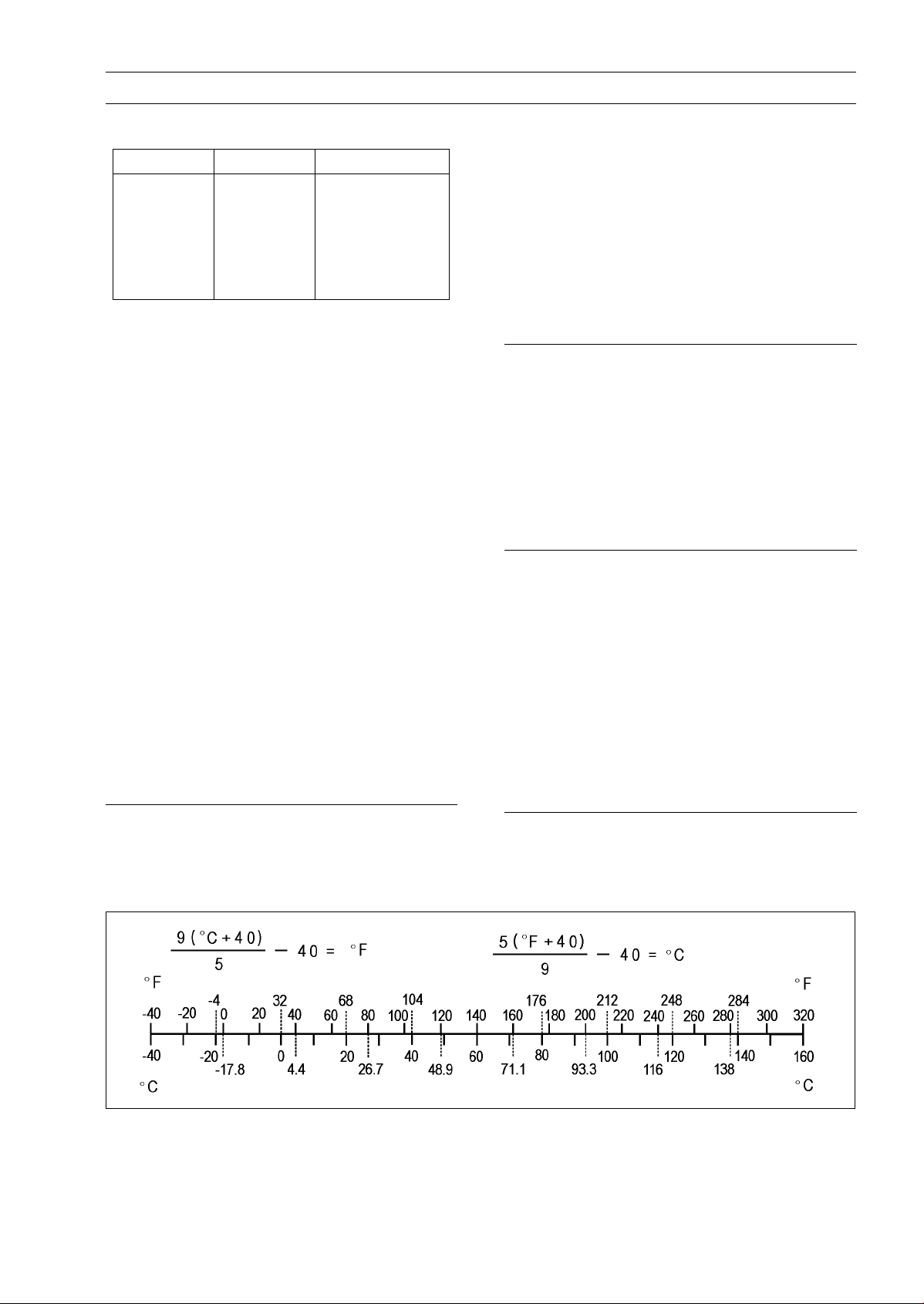
°C degree(s) Celsius oz ounce(s)
CDI capacitive discharge ignition Pa pascal(s)
cmHg centimeters of mercury PS horsepower
cu in.
DC direct current qt quart(s)
EMI Electro-Magnetic Interference r revolution
F farad(s) r/min, rpm revolution(s) per minute
°F degree(s) Fahrenheit s second(s)
ft foot, feet SOHC single overhead camshaft
g
gal gallon(s) TIR total indicator
h hour(s) V volt(s)
HP horsepower(s) W watt(s)
in. inch(es) ohm(s)
ISC Idle Speed Control
cubic inch(es)
gram(s) (mass) TDC
m
psi
meter(s)
pound(s) per square inch
top dead center
reading
Page 7
Foreword
This manual is designed primarily for use by
trained mechanics in a properly equipped shop.
However, it contains enough detail and basic information to make it useful to the owner who desires to perform his own basic maintenance and
repair work. A basic knowledge of mechanics,
the proper use of tools, and workshop procedures must be understood in order to carry out
maintenance and repair satisfactorily. Whenever the owner has insufficient experience or
doubts his ability to do the work, all adjustments, maintenance, and repair should be carried out only by qualified mechanics.
In order to perform the work efficiently and
to avoid costly mistakes, read the text, thoroughly familiarize yourself with the procedures
before starting work, and then do the work carefully in a clean area. Whenever special tools or
equipment are specified, do not use makeshift
tools or equipment. Precision measurements
can only be made if the proper instruments are
used, and the use of substitute tools may adversely affect safe operation.
For the duration of the warranty period,
we recommend that all repairs and scheduled
maintenance be performed in accordance with
this service manual. Any owner maintenance or
repair procedure not performed in accordance
with this manual may void the warranty.
To get the longest life out of your vehicle.
Follow the Periodic Maintenance Chart in the
•
Service Manual.
Be alert for problems and non-scheduled
•
maintenance.
Use proper tools and genuine Kawasaki Mo-
•
torcycle parts. Special tools, gauges, and
testers that are necessary when servicing
Kawasaki motorcycles are introduced by the
Service Manual. Genuine parts provided as
spare parts are listed in the Parts Catalog.
Follow the procedures in this manual care-
•
fully. Don’t take shortcuts.
Remember to keep complete records of main-
•
tenance and repair with dates and any new
parts installed.
How to Use This Manual
In this manual, the product is divided into
its major systems and these systems make up
the manual’s chapters. The Quick Reference
Guide shows you all of the product’s system
and assists in locating their chapters. Each
chapter in turn has its own comprehensive Table of Contents.
For example, if you want ignition coil information, use the Quick Reference Guide to locate
the Electrical System chapter. Then, use the
Table of Contents on the first page of the chapter to find the Ignition Coil section.
Whenever you see symbols, heed their instructions! Always follow safe operating and
maintenance practices.
DANGER
DANGER indicates a hazardous situa-
tion which, if not avoided, will result in
death or serious injury.
WARNING
WARNING indicates a hazardous situa-
tion which, if not avoided, could result
in death or serious injury.
NOTICE
NOTICE is used to address practices not
related to personal injury.
This manual contains four more symbols
which will help you distinguish different types
of information.
NOTE
NOTE indicates information that may help
○
or g uide you in the operation or service of
the vehicle.
Indicates a procedural step or work to be
•
done.
Indicates a procedural sub-step or how to do
the work of the procedural step it follows. It
also precedes the text of a NOTE.
Indicates a conditional step or what action to
take based on the results of the test or inspec-
tion in the procedural step or sub-step it fol-
lows.
In most chapters an exploded view illustration
of the system components follows the Table of
Contents. In these illustrations you will find the
instructions indicating which parts require specified tightening torque, oil, grease or a locking
agent during assembly.
Page 8

Page 9

GENERAL INFORMATION 1-1
General Information
Table of Contents
Before Servicing ..................................................................................................................... 1-2
Model Identification................................................................................................................. 1-7
General Specifications............................................................................................................ 1-9
Unit Conversion Table ............................................................................................................ 1-11
1
Page 10
1-2 GENERAL INFORMATION
Before Servicing
Before starting to perform an inspection service or carry out a disassembly and reassembly operation on a motorcycle, read the precautions given below. To facilitate actual operations, notes, illustrations, photographs, cautions, and detailed descriptions have been included in each chapter wherever
necessary. This section explains the items that require particular attention during the removal and
reinstallation or disassembly and reassembly of general parts.
Especially note the following.
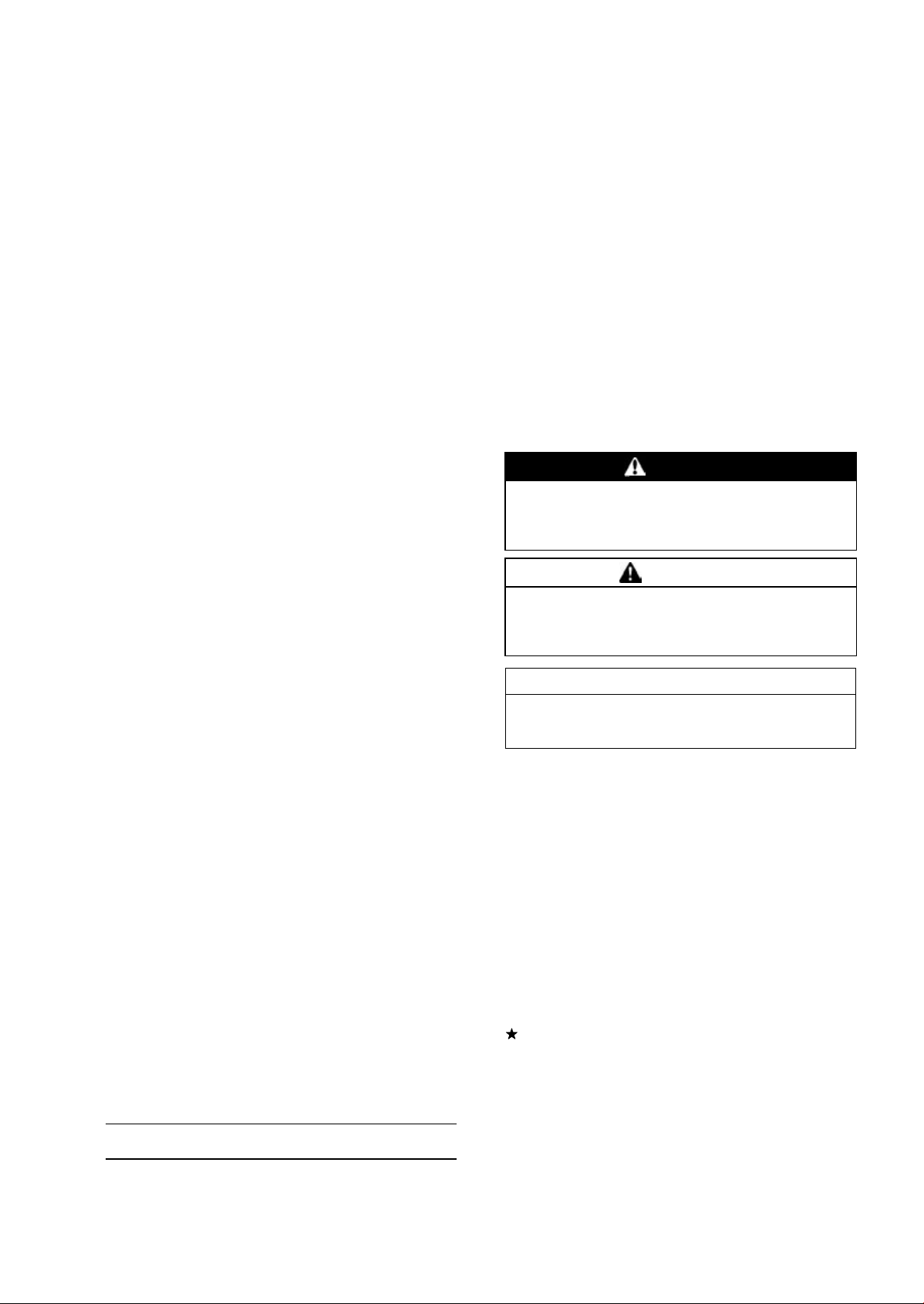
Battery Ground
Before completing any service on the motorcycle, disconnect the battery cables from the battery to prevent the engine from accidentally turning over. Disconnect the ground
cable (–) first and then the positive (+). When completed
with the service, first connect the positive (+) cable to the
positive (+) terminal of the battery then the negative (–) cable to the negative terminal.
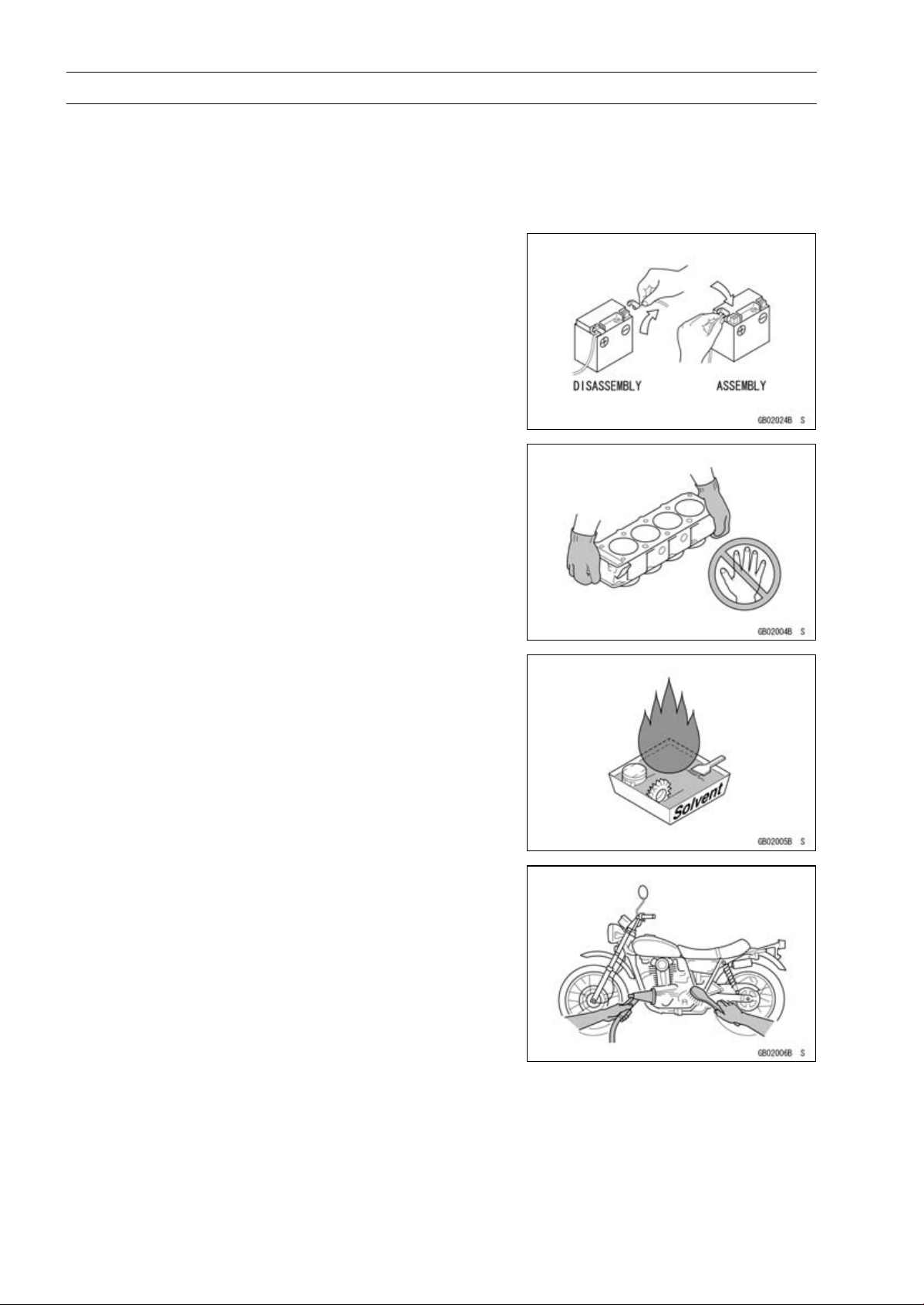
Edges of Parts
Lift large or heavy parts wearing gloves to prevent injury
from possible sharp edges on the parts.
Solvent
Use a high flash-point solvent when cleaning parts. High
flash-point solvent should be used according to directions
of the solvent manufacturer.
Cleaning Vehicle before Disassembly
Clean the vehicle thoroughly before disassembly. Dirt or
other foreign materials entering into sealed areas during vehicle disassembly can cause excessive wear and decrease
performance of the vehicle.
Page 11
Before Servicing
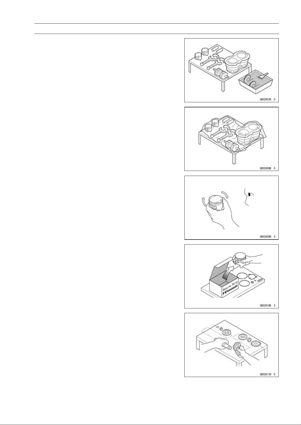
Arrangement and Cleaning of Removed Parts
Disassembled parts are easy to confuse. Arrange the
parts according to the order the parts were disassembled
and clean the parts in order prior to assembly.
Storage of Remov ed Parts
After all the parts including subassembly parts have been
cleaned, store the parts in a clean area. Put a clean cloth
or plastic sheet over the parts to protect from any foreign
materials that may collect before re-assembly.
GENERAL INFORMATION 1-3
Inspection
Reuse of worn or damaged parts may lead to serious accident. Visually inspect removed parts for corrosion, discoloration, or other damage. Refer to the appropriate sections
of this manual for service limits on individual parts. Replace
the parts if any damage has been found or if the part is beyond its service limit.
Replacement Parts
Replacement Parts must be KAWASAKI genuine or
recommended by KAWASAKI. Gaskets, O-rings, oil seals,
grease seals, circlips, cotter pins or self-locking nuts must
be replaced with new ones whenever disassembled.
Assembly Order
In most cases assembly order is the reverse of disassembly, however, if assembly order is provided in this Service
Manual, follow the procedures given.
Page 12
1-4 GENERAL INFORMATION
Before Servicing
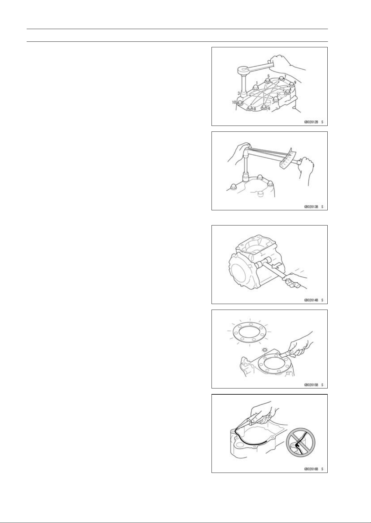
Tightening Sequence
Generally, when installing a part with several bolts, nuts,
or screws, start them all in their holes and tighten them to
a snug fit. Then tighten them according to the specified sequence to prevent case warpage or deformation which can
lead to malfunction. Conversely when loosening the bolts,
nuts, or screws, first loosen all of them by about a quarter turn and then remove them. If the specified tightening
sequence is not indicated, tighten the fasteners alternating
diagonally.
Tightening Torque
Incorrect torque applied to a bolt, nut, or screw may
lead to serious damage. Tighten fasteners to the specified
torque using a good quality torque wrench. Often, the
tightening sequence is followed twice-initial tightening and
final tightening with torque wrench.
All of the tightening torque values are for use with dry,
solvent - cleaned threads unless otherwise indicated. If a
fastener which should have dry, clean threads gets contaminated with lubricant, etc., applying even the specified torque
could damage it.
Force
Use common sense during disassembly and assembly,
excessive force can cause expensive or hard to repair damage. When necessary, remove screws that have a non
-permanent locking agent applied using an impact driver.
Use a plastic-faced mallet whenever tapping is necessary.
Gasket, O-ring
Hardening, shrinkage, or damage of both gaskets and
O-rings after disassembly can reduce sealing performance.
Remove old gaskets and clean the sealing surfaces thoroughly so that no gasket material or other material remains.
Install the new gaskets and replace the used O-rings when
re-assembling.
Liquid Gasket, Non-permanent Locking Agent
For applications that require Liquid Gasket or a
Non-permanent Locking Agent, c lean the surfaces so
that no oil residue remains before applying liquid gasket or
non-permanent locking agent. Do not apply them excessively. Excessive application can clog oil passages and
cause serious damage.
Page 13
Before Servicing
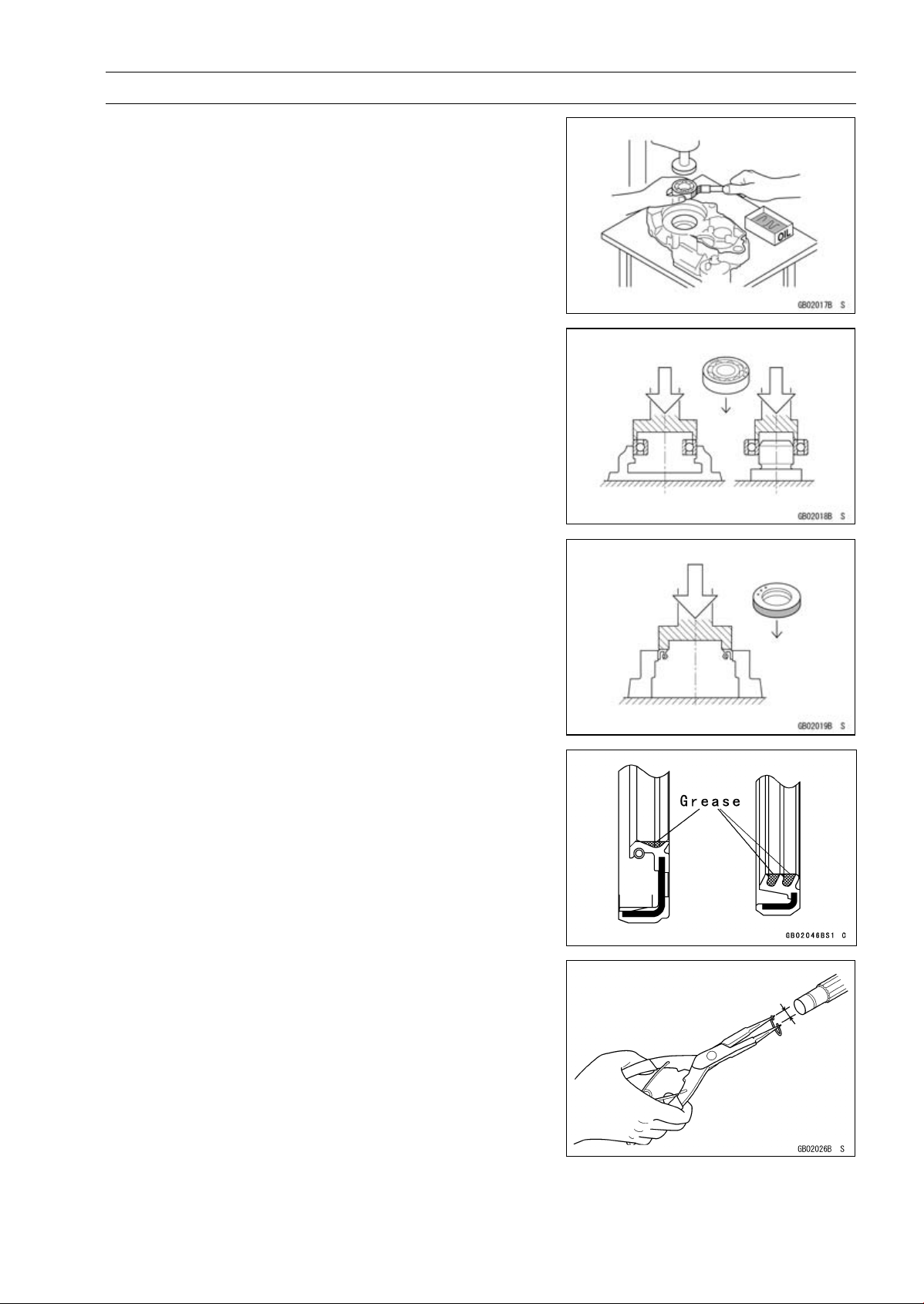
Press
For items such as bearings or oil seals that must be
pressed into place, apply small amount of oil to the contact area. Be sure to maintain proper alignment and use
smooth movements when installing.
Ball Bearing and Needle Bearing
Do not remove pressed ball or needle unless removal is
absolutely necessary. Replace with new ones whenever
removed. Press bearings with the manufacturer and size
marks facing out. Press the bearing into place by putting
pressure on the correct bearing race as shown.
Pressing the incorrect race can cause pressure between
the i nner and outer race and result in bearing damage.
GENERAL INFORMATION 1-5
Oil Seal, Grease Seal
Do not remove pressed oil or grease seals unless removal
is necessary. Replace with new ones whenever removed.
Press new oil seals with manufacture and size marks facing
out. Make sure the seal is aligned properly when installing.
Apply specified grease to the lip of seal before installing
the seal.
Circlips, Cotter Pins
Replace the circlips or cotter pins that were removed with
new ones. Take care not to open the clip excessively when
installing to prevent deformation.
Page 14
1-6 GENERAL INFORMATION
Before Servicing
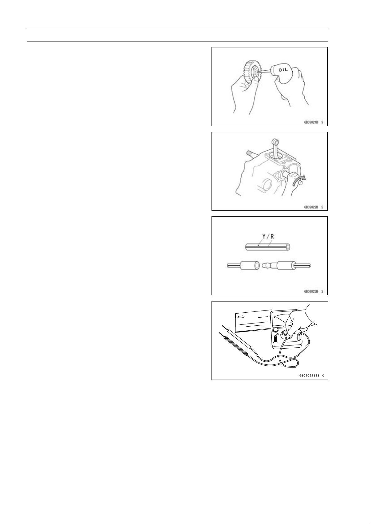
Lubrication
It is important to lubricate rotating or sliding parts during
assembly to minimize wear during initial operation. Lubrication points are called out throughout this manual, apply
the specific oil or grease as specified.
Direction of Engine Rotation
When rotating the crankshaft by hand, the free play
amount of rotating direction will affect the adjustment. Rotate the crankshaft to positive direction (clockwise viewed
from output side).
Electrical Leads
A two-color lead is identified first by the primary color and
then the stripe color. Unless instructed otherwise, electrical
leads must be connected to those of the same color.
Instrument
Use a meter that has enough accuracy for an accurate
measurement. Read the manufacture’s instructions thoroughly before using the meter. Incorrect values may lead
to improper adjustments.
Page 15
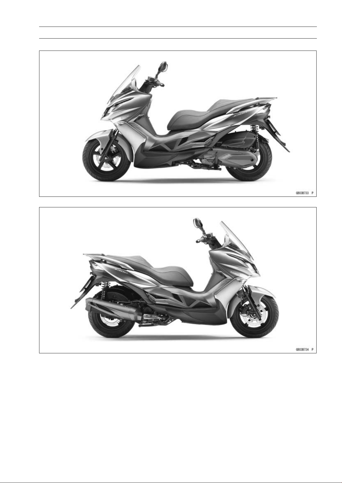
Model Identification
SC300AE Left Side View
GENERAL INFORMATION 1-7
SC300AE Right Side View
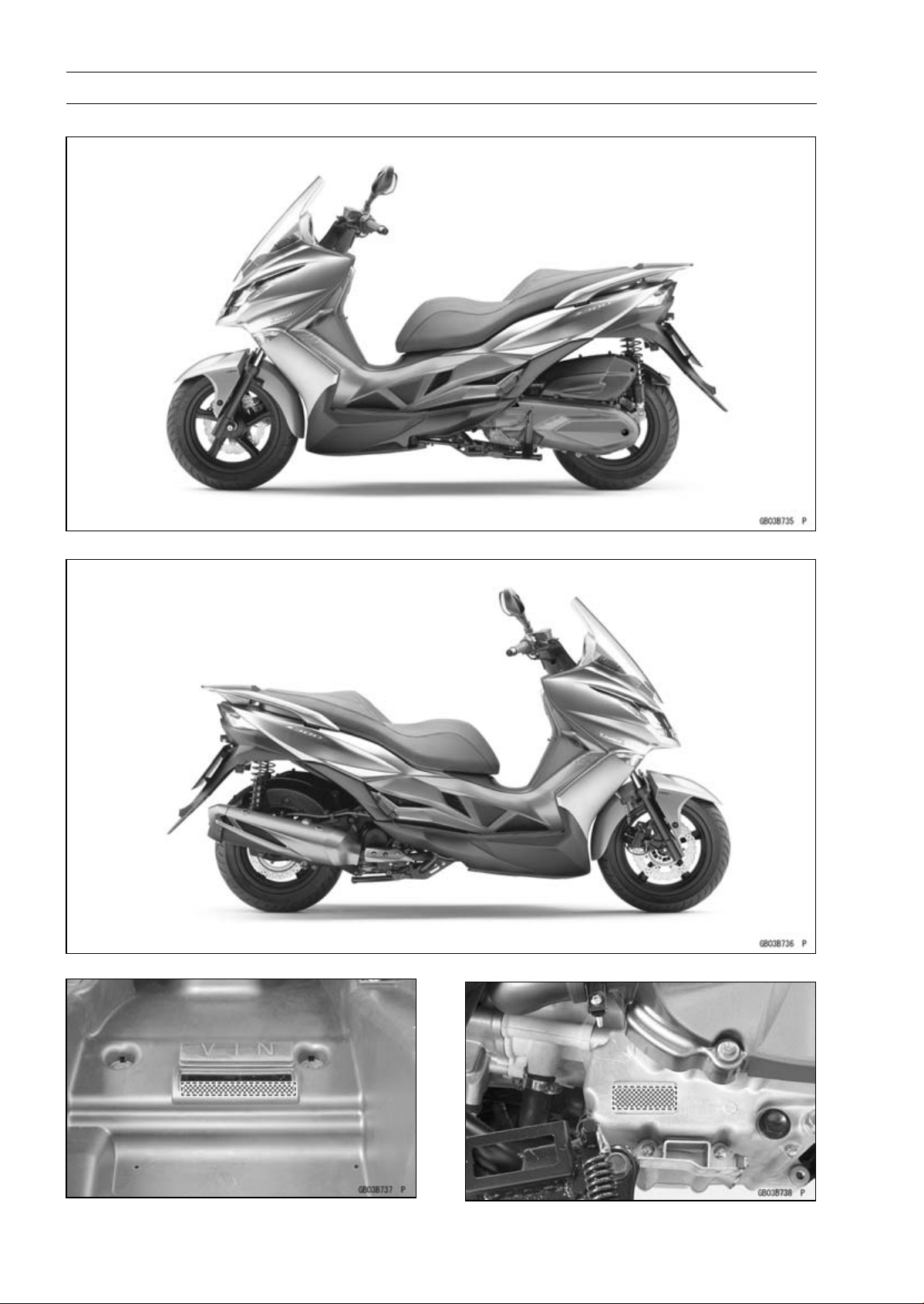
Page 16
1-8 GENERAL INFORMATION
Model Identification
SC300BE Left S ide View
SC300BE Right Side View
Frame Number Engine Number
Page 17
GENERAL INFORMATION 1-9
General Specifications
Items SC300AE ∼ AF/BE ∼ BF
Dimensions
Overall Length 2 235 mm (87.99 in.)
Overall Width 775 mm (30.51 in.)
Overall Height 1 260 mm (49.61 in.)
Wheelbase 1 555 mm (61.22 in.)
Road Clearance 145 mm (5.71 in.)
Seat Height 775 mm (30.5 in.)
Curb Mass: 191 kg (421 lb)
Front
Rear 113kg(249lb)
Fuel Tank Capacity 13 L (3.4 US gal)
Performance
Minimum Turning Radius
Engine
Type 4-stroke, SOHC, single cylinder
Cooling System
Bore and Stroke 72.7 × 72.0 mm (2.86 × 2.83 in.)
Displacement 299 cm³ (18.2 cu in.)
Compression Ratio 10.8:1
Maximum Horsepower 20.3 kW (28 PS) @7 750 r/min (rpm)
Maximum Torque 28.7 N·m (2.9 kgf·m, 21 ft·lb) @6 250 r/min (rpm)
Fuel System: FI (Fuel Injection) KEIHIN 34 × 1
Minimum Octane Rating:
Research Octane
Number (RON)
Starting System
Ignition System ECU control (full transistor)
Timing Advance Electronically advanced
Ignition Timing
Spark Plug NGK CR7E
Valve Timing:
Intake:
Open 9° (BTDC)
Close 37° (ABDC)
Duration 226°
Exhaust:
Open 39° (BTDC)
Close 10° (ATDC)
Duration
Lubrication System Forced lubrication (wet sump)
78 kg (172 lb)
2.6 m (8.5 ft)
Liquid-cooled
91
Electric starter
10.0° BTDC @1 600 r/min (rpm) to 30.0° BTDC @7 750 r/min
(rpm)
229°
Page 18

1-10 GENERAL INFORMATION
General Specifications
Items SC300AE ∼ AF/BE ∼ BF
Engine Oil:
Type
Viscosity SAE 5W-50
Capacity 1.5L(1.6USqt)
Drive Train
Driving System V-Matic continuously variable
Primary Reduction Ratio 2.220 ∼ 0.790
Final Reduction Ratio 7.222
Over Drive Ratio 16.030 ∼ 5.700
Clutch Type Automatic, centrifugal
Frame
Type Tubular diamond
Caster (Rake Angle) 28°
Trail 113 mm (4.45 in.)
Front Tire:
Type MAXXIS, i PRO, Tubeless
Size 120/80-14 M/C 58S
Rear Tire:
Type MAXXIS, PRO, Tubeless
Size 150/70-13 M/C 64S
Rim Size:
Front J14×3.0
Rear J13×4.0
Front Suspension:
Type Telescopic fork
Wheel Travel 110 mm (4.33 in.)
Rear Suspension:
Type
Wheel Travel 100 mm (3.94 in.)
Brake Type:
Front
Rear
Electrical Equipment
Battery
Headlight:
Type Semi-sealed beam
Bulb:
High 12 V 35 W × 2
Low 12 V 35 W × 2
Tail/Brake Light
Alternator:
Type Three-phase AC
Maximum Output 25.0 A/14 V @10 000 r/min (rpm)
API SJ, SL or SM with JASO MA, MA1 or MA2
Swingarm
Single disc
Single disc
12V10Ah(10HR)
LED
Specifications are subject to change without notice, and may not apply to every country.
Page 19
Unit Conversion Table
GENERAL INFORMATION 1-11
Prefixes for Units:
Prefix Symbol Power
mega M × 1 000 000
kilo k ×1000
centi c ×0.01
milli m × 0.001
micro µ × 0.000001
Units of Mass:
kg ×2.205=lb
g × 0.03527 = oz
Units of Volume:
L × 0.2642 = gal (US)
L × 0.2200 = gal (IMP)
L × 1.057 =
L × 0.8799 =
L × 2.113 = pint (US)
L × 1.816 = pint (IMP)
mL × 0.03381 = oz (US)
mL × 0.02816 = oz (IMP)
mL × 0.06102 = c u in.
qt (US)
qt (IMP)
Units of Length:
km × 0.6214 = mile
m × 3.281 = ft
mm × 0.03937 = in.
Units of Torque:
N·m × 0.1020 = kgf·m
N·m × 0.7376 = ft·lb
N·m × 8.851 = in·lb
kgf·m × 9.807 = N·m
kgf·m × 7.233 = ft·lb
kgf·m × 86.80 = in·lb
Units of Pressure:
kPa × 0.01020 = kgf/cm²
kPa × 0.1450 = psi
kPa × 0.7501 = cmHg
kgf/cm² × 98.07 = kPa
kgf/cm² × 14.22 = psi
cmHg×1.333=kPa
Units of Speed:
km/h
× 0.6214 = mph
Units of Force:
N × 0.1020 = kg
N × 0.2248 = lb
kg ×9.807=N
kg ×2.205=lb
Units of Temperature:
Units of Power:
kW ×1.360=PS
kW ×1.341=HP
PS
PS × 0.9863 = HP
× 0.7355 = kW
Page 20

Page 21

PERIODIC MAINTENANCE 2-1
Periodic Maintenance
Table of Contents
Periodic Maintenance Chart .............. 2-2
Torque and Locking Agent................. 2-4
Specifications .................................... 2-8
Special Tools ..................................... 2-10
Periodic Maintenance Procedures..... 2-11
Fuel System (DFI)........................... 2-11
Air Cleaner Element
Replacement............................. 2-11
Idle Speed Inspection .................. 2-12
Idle Speed Adjustment................. 2-12
Throttle Control System
Inspection.................................. 2-12
Fuel System ................................. 2-13
Fuel Hose Replacement .............. 2-14
Cooling System............................... 2-16
Coolant Level Inspection.............. 2-16
Cooling System ............................ 2-16
Coolant Change ........................... 2-16
Engine Top End .............................. 2-19
Valve Clearance Inspection ......... 2-19
Valve Clearance Adjustment........ 2-20
Clutch.............................................. 2-20
Clutch Shoe Wear Inspection ..... 2-20
Engine Lubrication System ............. 2-20
Engine Oil Change....................... 2-20
Oil Service Indicator Light Reset.. 2-22
Oil Filter Replacement ................. 2-22
Oil Screen Inspection................... 2-23
Breather Hose Inspection ............ 2-23
Wheels/Tires................................... 2-23
Air Pressure Inspection................ 2-23
Wheels and Tires ......................... 2-24
Wheel Bearing Damage
Inspection.................................. 2-24
Converter ........................................ 2-25
Drive Belt Wear Inspection .......... 2-25
Drive Belt Replacement ............... 2-25
Final Drive....................................... 2-27
Final Gear Case Oil Change ........ 2-27
Brakes............................................. 2-28
Brake System............................... 2-28
Brake Fluid Level Inspection........ 2-29
Brake Fluid Change ..................... 2-30
Brake Hose Replacement ............ 2-31
Master Cylinder Rubber Parts
Replacement............................. 2-32
Caliper Rubber Parts
Replacement............................. 2-32
Brake Pad Wear Inspection ......... 2-35
Brake Light Switch Operation
Inspection .................................. 2-36
Suspension..................................... 2-36
Suspension System ..................... 2-36
Steering .......................................... 2-37
Steering Play Inspection .............. 2-37
Steering Play Adjustment............. 2-37
Steering Stem Bearing
Lubrication................................. 2-38
Electrical System ............................ 2-39
Lights and Switches Operation
Inspection .................................. 2-39
Headlight Aiming Inspection ........ 2-41
Engine Stop Switch Operation
Inspection .................................. 2-42
Spark Plug Replacement ............. 2-42
Others............................................. 2-43
Chassis Parts Lubrication ........... 2-43
Condition of Bolts, Nuts and
Fasteners Tightness Inspection 2-44
2
Page 22
2-2 PERIODIC MAINTENANCE
Periodic Maintenance Chart
The scheduled maintenance must be done in accordance with this chart to k eep the motorcycle in
good running condition.
The initial maintenance is vitally important and must not be neglected.
I: Inspection and Clean, Adjust, Lubricate or Replace if necessary
C: Clean
A: Adjust
R: Replace
L: Lubricate
*: Should be serviced by your Kawasaki dealer, unless you have the proper tools, service data
and are technically qualified.
**: In the interest of safety, we recommend these items be serviced only by your Kawasaki dealer.
Kawasaki recommends that your Kawasaki dealer road test your scooter after each periodic
maintenance service is completed.
FREQUENCY
ITEM MONTH 1 6 12 18 24 30 36
* Air cleaner element R R R R R R 2-11
* Idle speed I I I 2-12
Throttle control system (play,
*
smooth return, no drag)
* Fuel system I I I 2-13
Fuel hose
**
** Coolant I R I R I R 2-16
* Valve clearance I A I A I A 2-19
** Clutch shoe wear I I I 2-20
Engine oil and oil filter R R R R R R R 2-20
Engine oil screens (both right
*
and left)
Crankcase breather C C C C C C C 2-23
** Wheels/tires I I I I I I 2-23
Drive belt
*
* Transmissi
Brake system I I I I I I 2-28
Brake fluid
Brake hose Replace at every 4 years 2-31
Brake rubber parts
Brake pad wear I I I I I I 2-35
Brake light switch I I I I I I 2-36
Suspension system I I I 2-36
Steering stem bearings I I I I I I 2-38
Electrical system
*
Spark plug I R I R I R 2-42
on oil
Whichever
comes
first
*Odometer Reading
× 1 000 km (× 1 000 mil
1
(0.6)5(3)10(6)15(9)20(12)25(15)30(18)
I I I I I I 2-12
Replace at every 5 years 2-14
C R C R C R 2-23
I I I R I I 2-25
R R R R R R R 2-27
I R I R I R 2-29
Replace at every 48 000 km (30
000 mile) or 4 years (whichever
occurs earlier)
I I I I I I 2-39
e)
Page
See
2-32
Page 23

Periodic Maintenance Chart
PERIODIC MAINTENANCE 2-3
FREQUENCY
ITEM MONTH 1 6 12 18 24 30 36
Chassis parts L L L 2-43
Condition of bolts, nuts and
*
fasteners
Whichever
comes
first
*Odometer Reading
× 1 000 km (× 1 000 mile)
1
(0.6)5(3)10(6)15(9)20(12)25(15)30(18)
I I I I I I 2-44
See
Page
Page 24

2-4 PERIODIC MAINTENANCE
Torque and Locking Agent
Tighten all bolts and nuts to the proper torque using an accurate torque wrench. If insufficiently
tightened, a bolt or nut may become damaged, strip an internal thread, or break and then fall out. The
following table lists the tightening torque for the major bolts and nuts, and the parts requiring use of
a non-permanent locking agent or silicone grease etc. All of the values are for use with dry solvent cleaned threads unless otherwise indicated.
When checking the tightening torque of the bolts and nuts, first loosen the bolt or nut by half a turn
and then tighten to specified torque.
Letters used in the “Remarks” column mean:
AL: Tighten the two clamp bolts alternately two times to ensure even tightening torque.
EO: Apply engine oil.
G: Apply grease.
L: Apply a non-permanent locking agent.
Lh: Left-hand Threads
R: Replacement Parts
S: Follow the specified tightening sequence.
Si: Apply silicone grease.
SS: Apply silicone sealant.
Fastener
Fuel System (DFI)
Water Temperature Sensor (ECU) 12 1.2 106 in·lb
Fuel Injector Mounting Bolt 9.8 1.0 87 in·lb
Oxygen Sensor 25 2.5 18
Fuel Pump Mounting Screws 3.4 0.35 30 in·lb
Cooling System
Water Hose Clamp Screws 4.4 0.45 39 in·lb
Thermostat Housing Cover Bolts
Water Pump Cover Bolts 9.8 1.0 87 in·lb
Water Pump Impeller 12 1.2 106 in·lb Lh
Water Temperature Sensor (ECU)
Water Temperature Sensor (Meter) 7.4 0.75 65 in·lb SS
Engine Top End
Upper Camshaft Chain Guide Bolt
Rocker Shaft Stopper Bolt 8.8 0.90 78 in·lb L
Intake Manifold Stud Bolts 8.8 0.90 78 in·lb
Cylinder Head Stud Bolts 8.8 0.90 78 in·lb
Exhaust Pipe Manifold Stud Bolts 8.8 0.90 78 in·lb
Camshaft Sprocket Bolts 12 1.2 106 in·lb L
Cylinder Head Nuts (M10) (First)
Cylinder Head Nuts (M10) (Final) 37 3.8 27 S
Cylinder Head Nuts (M6) 9.8 1.0 87 in·lb S
Cylinder Head Bolts 9.8 1.0 87 in·lb S
Cylinder Bolts 9.8 1.0 87 in·lb S
Camshaft Chain Tensioner Mounting Bolts 12 1.2 106 in·lb
Camshaft Chain Tensioner Cap Bolt
Spark Plug 12 1.2 106 in·lb
Fuel Hose Bracket Bolt 9.8 1.0 87 in·lb
N·m kgf·m ft·lb
7.4 0.75 65 in·lb
12 1.2 106 in·lb
9.8 1.0 87 in·lb
20 2.0 15
4.4 0.45 39 in·lb
Torque
Remarks
S
Page 25

Torque and Locking Agent
PERIODIC MAINTENANCE 2-5
Fastener
Cylinder Head Cover Bolts
Intake Manifold Mounting Nuts 9.8 1.0 87 in·lb
Valve Adjusting Screw Locknuts 8.8 0.90 78 in·lb
Muffler Body Mounting Bolts 34 3.5 25
Exhaust Pipe Manifold Holder Nuts 20 2.0 15
Converter System
Left Crankcase Cover Bolts
Drive Face Nut 93 9.5 69
Clutch Outer Nut
Clutch Drive Plate Nut
Engine Lubrication System
Oil Screen Plug 9.3 0.95 82 in·lb
Oil Pump Screws 9.8 1.0 87 in·lb
Oil Separator Cover Bolts 9.8 1.0 87 in·lb
Oil Pressure Switch
Engine Oil Drain Bolt
Oil Filter Cap 9.3 0.95 82 in·lb L
Engine Removal/Installation
Engine Hanger Nuts 64 6.5 47 R
Engine Mounting Nut 49 5.0 36 R
Crankcase/Crankshaft
Crankcase Bolts
Engine Stud Bolts 12 1.2 106 in·lb EO
Starter Motor Clutch Bolts 20 2.0 15 L
Wheels/Tires
Front Axle 20 2.0 15
Rear Axle Nut 118 12.0 87.0 R
Sub Frame Bolts
Final Drive
Final Gear Case Cover Bolts
Oil Filler Bolt
Final Gear Case Oil Drain Bolt 9.8 1.0 87 in·lb
Brakes
Front Caliper Mounting Bolts
Front Wheel Rotation Sensor Bolt 12 1.2 106 in·lb
Brake Hose Banjo Bolts 34 3.5 25
Brake Disc Mounting Bolts 34 3.5 25 L
Brake Reservoir Cap Screws 1.6 0.16 14 in·lb
Master Cylinder Clamp Bolts
Brake Lever Pivot Bolt 2.0 0.20 18 in·lb
Brake Lever Pivot Bolt Locknut 9.8 1.0 87 in·lb
Brake Light Switch Screw
Bleed Valves 5.4 0.55 48 in·lb
N·m
9.8 1.0 87 in·lb
9.8 1.0 87 in·lb
54 5.5 40
54 5.5 40
23 2.3 17
25 2.5 18 R
9.8 1.0 87 in·lb
34 3.5 25
20 2.0 15
9.8 1.0 87 in·lb
34 3.5 25 L
12 1.2 106 in·lb
1.0 0.10 8.9 in·lb
Torque
Remarks
kgf·m ft·lb
Si
Page 26

2-6 PERIODIC MAINTENANCE
Torque and Locking Agent
Fastener
Brake Pad Pin 18 1.8 13 L
Rear Caliper Mounting Bolts 34 3.5 25 L
ABS Hydraulic Unit Mounting Nuts 7.8 0.80 69 in·lb
Suspension
Front Fork Clamp Bolts 26 2.7 19 AL
Front Fork Bottom Allen Bolts 29 3.0 21 L
Upper Rear Shock Absorber Nuts 39 4.0 29 R
Lower Rear Shock Absorber Bolts 39 4.0 29
Sub Frame Bolts
Steering
Steering Stem Nut 20 2.0 15
Steering Stem Lock Nut 62 6.3 46
Handlebar Mounting Nut 44 4.5 32 R
Frame
Grab Rail Mounting Bolts
Electrical System
Ignition Coil Mounting Nuts 12 1.2 106 in·lb
Starter Relay Terminal Nuts 29 3.0 21
Starter Motor Mounting Bolts 9.8 1.0 87 in·lb
Water Temperature Sensor (Meter) 7.4 0.75 65 in·lb SS
Water Temperature Sensor (ECU)
Alternator Rotor Nut 59 6.0 44
Alternator Cover Bolts 9.8 1.0 87 in·lb
Timing Inspection Cap
Alternator Cover Center Cap (SC300AE/BE) 4.4 0.45 39 in·lb
Alternator Cover Center Cap (SC300AF ∼/BF ∼) 9.8 1.0 87 in·lb
Stator Coil Bolts 9.8 1.0 87 in·lb
Crankshaft Sensor Bolts 4.4 0.45 39 in·lb
Starter Motor Clutch Bolts 20 2.0 15 L
Oxygen Sensor
N·m kgf·m ft·lb
34 3.5 25
24 2.4 18
12 1.2 106 in·lb
4.4 0.45 39 in·lb
25 2.5 18
Torque
Remarks
Page 27
PERIODIC MAINTENANCE 2-7
Torque and Locking Agent
The table below, relating tightening torque to thread diameter, lists the basic torque for the bolts and
nuts. Use this table for only the bolts and nuts which do not require a specific torque value. All of the
values are for use with dry solvent-cleaned threads.
Basic Torque for General Fasteners
Threads Diameter
(mm)
5 3.4 ∼ 4.9 0.35 ∼ 0.50 30 ∼ 43 in·lb
6 5.9 ∼ 7.8 0.60 ∼ 0.80 52 ∼ 69 in·lb
8 14 ∼ 19 1.4 ∼ 1.9 10 ∼ 13.5
10 25 ∼ 34 2.6 ∼ 3.5 19 ∼ 25
12 44 ∼ 61 4.5 ∼ 6.2 33 ∼ 45
14 73 ∼ 98 7.4 ∼ 10.0 54 ∼ 72
16 115 ∼ 155 11.5 ∼ 16.0 83 ∼ 115
18 165 ∼ 225 17.0 ∼ 23.0 125 ∼ 165
20 225 ∼ 325 23.0 ∼ 33.0 165 ∼ 240
N·m kgf·m ft·lb
Torque
Page 28

2-8 PERIODIC MAINTENANCE
Specifications
Item Standard Service Limit
Fuel System (DFI)
ThrottleGripFreePlay 2 ∼ 6 mm (0.08 ∼ 0.24 in.) –––
Idle Speed 1 600 ±100 r/min (rpm) –––
Air Cleaner Element Wet paper element –––
Cooling System
Coolant:
Type (Recommended) Permanent type of antifreeze
Color Green –––
Mixed Ratio Soft water 50%, coolant 50% –––
Freezing Point –35°C (–31°F) –––
Total Amount 1.5L(1.6USqt) –––
Engine Top End
Valve Clearance:
Exhaust 0.10 mm (0.0039 in.) –––
Intake 0.10 mm (0.0039 in.) –––
Converter
Drive Belt Width 25.2 mm (0.992 in.) 23.7 mm (0.933 in.)
Engine Lubrication System
Engine Oil:
Type API SJ, SL or SM with JASO MA, MA1 or
MA2
Viscosity SAE 5W-50 –––
Capacity 1.3L(1.4USqt) –––
1.5 L (1.6 US qt) (when engine is completely
dry)
Level Between upper and lower level lines (Wait 2
∼ 3 minutes after idling or running)
Wheels/Tires
Tread Depth:
Front ––– 1 mm (0.04 in.)
Rear ––– 1 mm (0.04 in.)
Air Pressure (when Cold):
Front 200 kPa (2.0 kgf/cm², 29 psi) –––
Rear
Final Drive
Final Gear Case Oil:
Viscosity
Capacity 0.23 L (0.24 US qt) at disassembly –––
Brakes
Brake Fluid:
Grade DOT4 –––
Brake Pad Lining Thickness:
Front 5 mm (0.20 in.) 1 mm (0.04 in.)
Rear 5.8 mm (0.23 in.) 1 mm (0.04 in.)
225 kPa (2.25 kgf/cm², 33 psi)
SAE 90
0.21 L (0.22 US qt) at change –––
–––
–––
–––
–––
–––
–––
Page 29

PERIODIC MAINTENANCE 2-9
Specifications
Item Standard Service Limit
Brake Light Timing:
Front
Rear Pulled ON –––
Electrical System
Spark Plug:
Type NGK CR7E –––
Gap 0.7 ∼ 0.8 mm (0.028 ∼ 0.031 in.)
Pulled ON
–––
–––
Page 30
2-10 PERIODIC MAINTENANCE
Special Tools
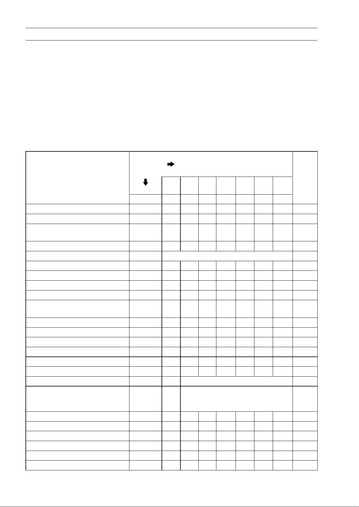
Inside Circlip Pliers:
57001-143
Steering Stem Nut Wrench:
57001-1100
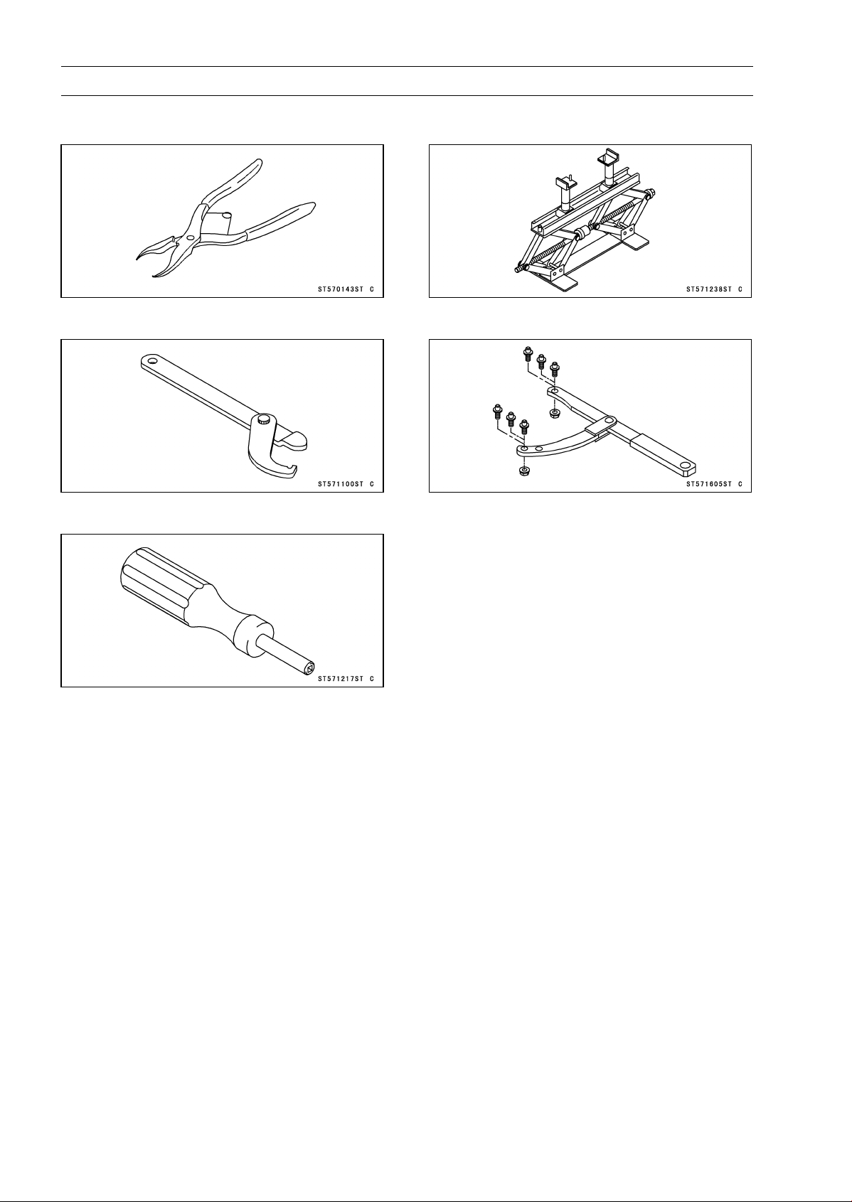
Valve Adjusting Screw Holder:
57001-1217
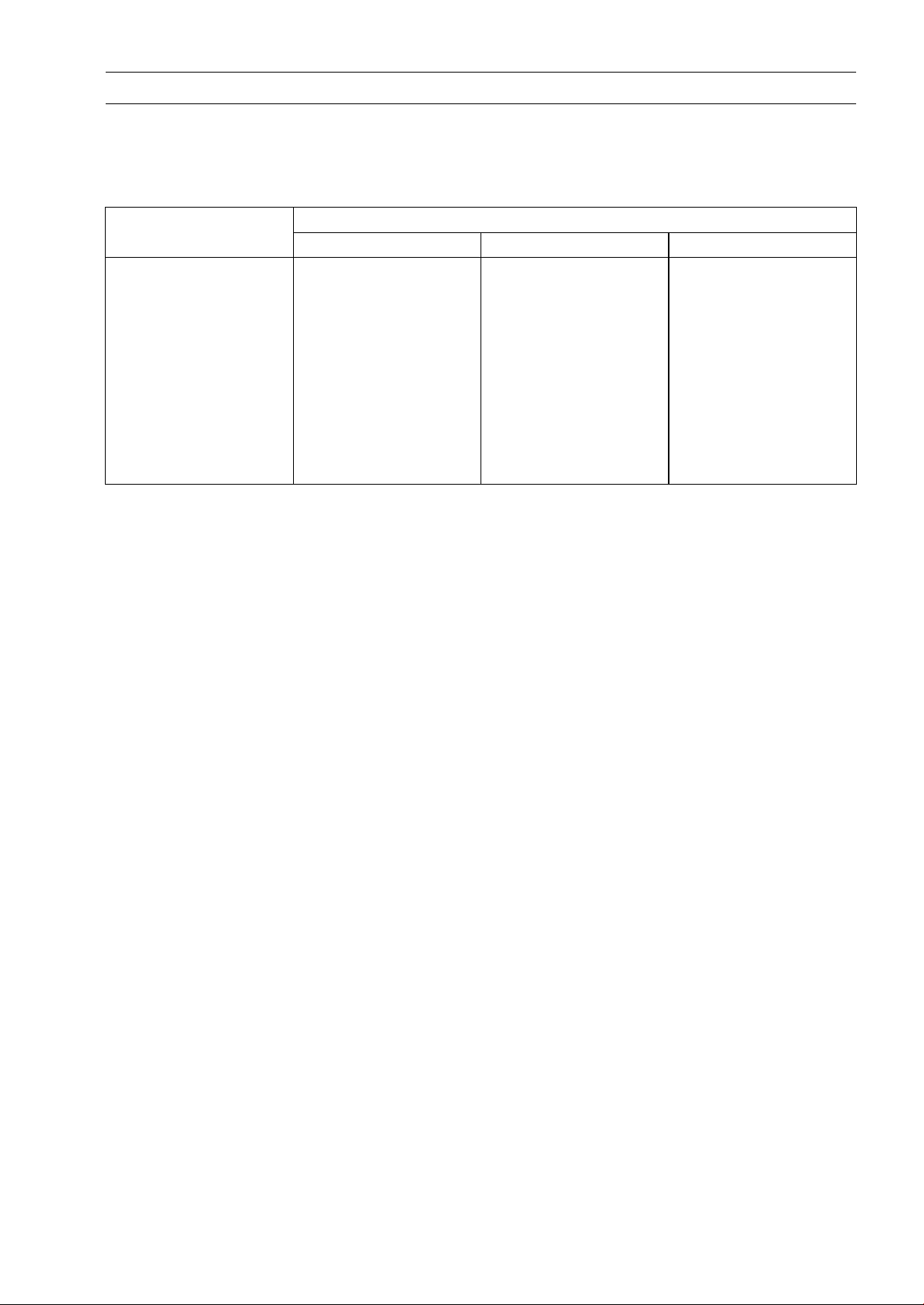
Jack:
57001-1238
Flywheel & Pulley Holder:
57001-1605
Page 31

Periodic Maintenance Procedures
Fuel System (DFI)
Air Cleaner Element Rep lacement
NOTE
In dusty areas, the element should be replaced more
○
frequently than the recommended interval.
WARNING
If dirt or dust is allowed to pass through into the
throttle body assy, the throttle may become stuck,
possibly causing accident. Replace the air cleaner
element according to the maintenance chart.
NOTICE
If dirt gets through into the engine, excessive en-
gine wear and possibly engine damage will occur.
Remove:
•
Screws [A]
Air Cleaner Cover [B]
PERIODIC MAINTENANCE 2-11
Remove:
•
Bolts [A]
Air Cleaner Element [B]
Install a new element and tighten its bolts.
•
NOTICE
Use only the recommended air cleaner element. Us-
ing another air cleaner element will wear the engine
prematurely or lower the engine performance.
Install the air cleaner cover and tighten its screws.
•
Page 32

2-12 PERIODIC MAINTENANCE
Periodic Maintenance Procedures
Idle Speed Inspection
Start the engine and warm it up thoroughly.
•
With the engine idling, turn the handlebars to both sides
•
[A].
If handlebars movement changes the idle speed, the
throttle cables may be improperly adjusted or incorrectly
routed, or damaged. Be sure to correct any of these
conditions before riding ( see Throttle Control System
Inspection and Cable, Wire, and Hose Routing section in
the Appendix chapter).
WARNING
Operation with improperly adjusted, incorrectly
routed or damaged cables could result in an unsafe
riding condition. Follow the service manual to be
make sure to correct any of these conditions.
Check the idle speed.
•
If the idle speed is out of specified range, check the idle
speed control valve actuator (see Idle Speed Control
Valve Actuator Inspection in the Fuel System (DFI) chapter).
Idle Speed
Standard: 1 600 ±100 r/min (rpm)
Idle Speed Adjustment
NOTE
This motorcycle is equipped with the idle speed control
○
valve. The idle speed is adjusted automatically at the
specified value (1 600 r/min (rpm)) by the idle speed
control valve system. Therefore, it is not necessary to
adjust the idle speed normally.
Throttle Control System Inspection
Check the throttle grip free play [A].
•
If the free play is incorrect, adjust the throttle cables.
Throttle G rip Free Play
Standard: 2 ∼ 6 mm (0.08 ∼ 0.24 in.)
Check that the throttle grip [B] moves smoothly from full
•
open to close, and the throttle closes quickly and completely by the return spring in all steering positions.
If the throttle grip does not return properly, check the throttle cables routing, grip free play, and cable damage. Then
lubricate the throttle cable.
Run the engine at the idle speed, and turn the handlebars
•
all the way to the right and left to ensure that the idle speed
does not change.
If the idle speed increases, check the throttle cable free
play and the cable routing.
Page 33

Periodic Maintenance Procedures
If necessary, adjust the throttle cable as follows.
Slide the dust cover [A].
•
Loosen the locknut [A].
•
Turn the adjuster [B] until the proper amount of throttle
•
grip play is obtained.
Tighten the locknut.
•
PERIODIC MAINTENANCE 2-13
If the throttle grip free play cannot be adjusted with the
adjuster of the throttle cable upper end, adjust the free
play with the adjuster of the throttle cable lower end.
Remove the storage box (see Storage Box Removal in
•
the Frame chapter).
Loosen the locknuts [A] and adjust the throttle cable so
•
that the throttle grip free play is until the proper amount.
Tighten the locknuts.
•
If the free play can not be adjusted with the adjuster, re-
place the cable.
Fuel System
Fuel Hose Inspection (fuel leak, damage, installation
condition)
If the motorcycle is not properly handled, the high pres-
sure inside the fuel line can cause fuel to leak [A] or the
hose to burst. Remove the fuel tank (see Fuel Tank Re-
moval i n the Fuel System (DFI) chapter) and check the
fuel hoses.
Replace the fuel hose if any fraying, cracks [B] or bulges
[C] are noticed.
Check that the fuel hose is routed according to Cable,
•
Wire, and Hose Routing section in the Appendix chapter.
Replace the hose if it has been sharply bent or kinked.
Hose Clamps [A]
Fuel Hose [B]
Page 34

2-14 PERIODIC MAINTENANCE
Periodic Maintenance Procedures
Check that the fuel hose clamps are securely installed.
•
Push and pull [A] the fuel hose [B] back and forth, and
make sure it is locked.
WARNING
Leaking fuel can cause a fire or explosion resulting
in serious burns. Make sure the hose clamp is installed correctly.
If it does not locked, reinstall the new hose clamp.
Fuel Hose Replacement
Remove the fuel tank cap cover (see Fuel Tank Cap
•
Cover Removal in the Frame chapter).
NOTE
Ensure the fuel hose without any pressure, and then
○
remove the fuel pump.
STEP 1: Disconnect the fuel pump connector.
STEP 2: Turn the ignition switch on. Starting the engine
until the engine stop working.
Be sure to place a piece of cloth [A] around the fuel hose
•
connection.
Wipe off the dirt of the surface [B] around the connection
•
using a cloth or a soft brush.
Clear the hook [A] of the hose clamp with a suitable tool
•
[B] and flat tip screwdriver [C], and remove the hose
clamp.
Insert the flat tip screwdriver under the hook while clamp-
ing the hose clamp with the suitable tool.
Recommend Tool: OETIKER 1098
WARNING
Fuel is flammable and explosive under certain conditions and can cause severe burns. Be prepared
for fuel spillage; any spilled fuel must be completely
wiped up immediately. When the fuel hose is disconnected, fuel spills out from the hose and the
pipe because of residual pressure. Cover the hose
connection with a piece of clean cloth to prevent
fuel spillage.
Page 35

Periodic Maintenance Procedures
Clean the fuel pipe [A].
•
If the new hose is not installed soon, cover the fuel pipe
•
with the vinyl bag [B] to keep it clean.
Remove the vinyl bag on the pipe.
•
Check that there are no flaws, burrs, and adhesion of
•
foreign materials on the fuel pipe [A].
PERIODIC MAINTENANCE 2-15
Replace the fuel hose and hose clamps with new ones,
•
and install them.
Run the fuel outlet hose correctly (see Cable, Wire, and
•
Hose Routing section in the Appendix chapter).
Pinch the new hose clamp [A] with a suitable tool [B] to
•
install it.
Recommend Tool: OETIKER 1098
Push and pull [A] the fuel hose [B] back and forth, and
•
make sure it is locked and does not come off.
WARNING
Leaking fuel can cause a fire or explosion resulting
in severe burns. Make sure the fuel hose joint is
installed correctly on the delivery pipe and that it
doesn’t leak.
If it comes off, reinstall the hose together with the new
hose clamp.
Start the engine and check the fuel hose for leaks.
•
Page 36

2-16 PERIODIC MAINTENANCE
Periodic Maintenance Procedures
Cooling System
Coolant Level Inspection
NOTE
Check the level when the engine is cold (room or ambi-
○
ent temperature).
Check the coolant level in the reserve tank [A] with
•
the motorcycle held perpendicular (Do not use the side
stand).
If the coolant level is lower than the “LOW” level line [B],
remove the reserve tank cap cover [C] by removing screw,
and then remove the reserve tank cap [D] and add coolant
to the “FULL” level line [E].
NOTICE
For refilling, add the specified mixture of coolant
and soft water. Adding water alone dilutes the
coolant and degrades its anticorrosion properties.
The diluted coolant can attack the aluminum engine parts. In an emergency, soft water alone can
be added. But the diluted coolant must be returned
to the correct mixture ratio within a few days.
If coolant must be added often or the reservoir tank
has run completely dry, there is probably leakage in
the cooling system. Check the system for leaks.
Coolant ruins painted surfaces. Immediately wash
away any coolant that spills on the frame, engine,
wheels or other painted parts.
Cooling System
Water Hose and Pipe Inspection (coolant leak, damage,
installation condition)
The high pressure inside the radiator hose can cause
coolant to leak [A] or the hose to burst if the line is not
properly maintained.
Visually inspect the hoses for signs of deterioration.
•
Squeeze the hoses. A hose should not be hard and
brittle, nor should it be soft or swollen.
Replace the hose if any fraying, cracks [B] or bulges [C]
are noticed.
Check that the hoses are securely connected and clamps
•
are tightened correctly.
Torque - Water Hose Clamp Screws: 4.4 N·m (0.45 kgf·m,
39 in·lb)
Coolant Change
WARNING
Coolant can be extremely hot and cause severe
burns, is toxic and very slippery. Do not remove
the radiator cap or attempt to change the coolant
when the engine is hot; allow it cool completely.
Immediately wipe any spilled coolant from tires,
frame, engine or other painted parts. Do not ingest
coolant.
Page 37

Periodic Maintenance Procedures
Remove:
•
Front Center Cover (see Front Center Cover R emoval in
the Frame chapter)
Storage Box (see Storage Box Removal in the Frame
chapter)
Radiator Cap [A]
Remove the radiator cap in two steps. First turn the cap
counterclockwise to the first stop. Then push and turn it
further in the same direction and remove the cap.
Place a container under the drain bolt [A] of the water
•
pump cover.
Drain the coolant from the radiator by removing the drain
•
bolt.
PERIODIC MAINTENANCE 2-17
Remove the bolt [A] on the thermostat housing cover to
•
drain the coolant completely.
Remove:
•
Front Fairing (see Front Fairing Removal in the Frame
chapter)
Bolts [A]
Cap [B]
Pour the coolant into a container.
•
Install the coolant reserve tank [C] and tighten the bolts.
•
Tighten the drain bolt with new gasket.
•
Page 38

2-18 PERIODIC MAINTENANCE
Periodic Maintenance Procedures
When filling the coolant, choose a suitable mixture ratio
•
by referring to the coolant manufacturer’s directions.
NOTICE
Soft or distilled water must be used with the antifreeze in the cooling system.
If hard water is used in the system, it causes scales
accumulation in the water passages, and considerably reduces the efficiency of the cooling system.
Water and Coolant Mixture Ratio (Recommended)
Soft Water: 50%
Coolant: 50%
Freezing Point:
Tota l A m ount:
Fill the radiator up to the filler neck [A] with coolant.
•
Pour in the coolant slowly so that it can expel the air
○
from the engine and radiator.
–35°C (–31°F)
1.5 L (1.6 US qt)
NOTE
Check the cooling system for leaks.
•
Remove the bolt [A] on the thermostat housing cover to
•
bleed the air.
Tap the radiator hoses to force any air bubbles caught
•
inside.
Tighten the bolt with a new gasket after bleeding the air.
•
Fill the radiator up to the filler neck with coolant.
•
Fill the reserve tank up to the “FULL” level line [A] with
•
coolant and install the cap [B].
Install the radiator cap.
•
Start the engine, warm it up thoroughly until the radiator
•
fan turns on and then stop the engine.
Check the coolant level in the reserve tank after the en-
•
gine cools down.
If the coolant level is lower than the “LOW” level line [C],
add coolant to the “FULL” level line.
NOTICE
Do not add more coolant above the “FULL” level
line.
Page 39

Periodic Maintenance Procedures
Engine Top End
Valve Clearance Inspection
NOTICE
If valve clearance is left unadjusted, the wear will
eventually cause the valves to remain partly open,
which lowers performance, burns the valves and
the valve seats, and may cause serious engine dam-
age.
NOTE
Valve clearance must be checked when the engine is
○
cold (at room temperature).
Remove:
•
Cylinder Head Cover (see Cylinder Head Cover Removal in the Engine Top End chapter)
Timing Inspection Cap [A]
Alternator Cover Center Cap [B]
PERIODIC MAINTENANCE 2-19
Turn the crankshaft clockwise, and align the “T” mark [A]
•
on the alternator rotor with the groove [B] on the alternator
cover.
Check that the projection [A] and lines [B] on the camshaft
sprocket is in position. This shows that the piston TDC is
at the end of the compression stroke.
Page 40

2-20 PERIODIC MAINTENANCE
Periodic Maintenance Procedures
Using a thickness gauge [A], measure the valve clearance
•
between the adjusting screw and valve stem.
Measure the both valves at a time.
Valve Cleara nce
Standard:
Exhaust 0.10 mm (0.0039 in.)
Intake 0.10 mm (0.0039 in.)
If the valve clearance is not within the specified range,
adjust it.
Valve Clearance Adjustment
Loosen the valve adjusting screw locknut [A] and insert
•
the thickness gauge [B] between the valve and adjusting
screw [C], and turn the screw until the adjusting screw
stops.
Tighten the valve adjusting screw locknut.
•
Special Tool - Valve Adjusting Screw Holder [D]:
57001-1217
Torque - Valve Adjusting Screw Locknut: 8.8 N·m (0.90
kgf·m, 79 in·lb)
Install the removed parts (see appropriate chapters).
•
Clutch
Clutch Shoe Wear Inspection
Remove the clutch outer (see Clutch/Driven Pulley Re-
•
moval in the Converter System chapter).
Check the clutch shoes for damage.
•
If there is any damaged part, replace it.
Measure the clutch lining thickness [A].
•
Iftheliningthicknessiswornovertheservicelimit,replace the clutch shoe.
Clutch Lining Thickness
Standard: 4.0 mm (0.16 in.)
Service Limit: 2.0 mm (0.08 in.)
Engine Lubrication System
Engine Oil Change
Warm up the engine thoroughly so that the oil will pick up
•
any sediment and drain easily. Then stop the engine.
Place an oil pan beneath the engine.
•
Remove the oil filler cap/dipstick [A].
•
Page 41

Periodic Maintenance Procedures
Remove the engine oil drain bolt [A] from the bottom of
•
the engine, and let the oil drain completely.
Replace the drain bolt assy with a new one.
•
Install the new drain bolt.
•
Tighten:
•
Torque - Engine Oil Drain Bolt: 25 N·m (2.5 kgf·m, 18 ft·lb)
Pour in the specified type and amount of oil.
•
Recommended Engine Oil
Typ e :
Viscosity:
Capacity: 1.3 L (1.4 US qt)
API SJ, SL or SM with JASO MA, MA1 or
MA2
SAE 5W-50
1.5 L (1.6 US qt) (when engine is completely
dry)
PERIODIC MAINTENANCE 2-21
NOTE
Do not add any chemical additive to the oil. Oils fulfilling
○
the above requirements are fully formulated and provide
adequate lubrication for both the engine and the clutch.
Although 5W-50 engine oil is the recommended oil
○
for most conditions, the oil viscosity may need to be
changed to accommodate atmospheric conditions in
your riding area.
Check the oil level (see Oil Level Inspection in the Engine
•
Lubrication System chapter).
Replace the oil filler cap/dipst
•
Apply grease to the O-ring.
•
Tighten the oil filler cap/dipstick securely.
•
ick O-ring with a new one.
Page 42

2-22 PERIODIC MAINTENANCE
Periodic Maintenance Procedures
Oil Service Indicator Light Reset
NOTE
The yellow oil service indicator light (LED) [A] goes on
○
for changing the engine oil when the distance of the
service mode [B] reaches 5 000 km (3 107 mile). The
yellow oil service indicator light (LED) goes off when the
oil service mode is reset. Reset the oil service mode
after changing the engine oil.
It is not necessary to reset the oil service mode at the
○
1000 km initial maintenance of the oil change.
Push the ADJ button [C] for 2 seconds to display the ser-
•
vice mode.
Push the Reset button [D] and hold it in. After 2 seconds,
•
the y ellow oil service indicator light (LED) goes off and the
service mode display turns to 0.0.
Oil Filter Replacement
Drain the engine oil (see Engine Oil Change).
•
Remove:
•
Oil Filter Cap [A]
Oil Filter
Replace the oil filter with a new one.
•
Apply engine oil to the grommet [A].
•
Install the oil filter so that the grommet faces to the engine
•
side.
Replace the oil filter cap O-ring [A] with a new one.
•
Apply grease to the O-ring and install it.
•
Install the spring [B].
•
Install the oil filler cap and tighten it securely.
•
Torque - Oil Filter Cap: 9.3 N·m (0.95 kgf·m, 82 in·lb)
Pour in the specified type and amount of oil (see Engine
•
Oil Change).
Page 43

Periodic Maintenance Procedures
Oil Screen Inspection
Remove the both right and left oil screens (see Oil Screen
•
Removal in the Engine Lubrication System chapter).
Check the oil screens [A] carefully for any damage, holes,
•
and broken wires.
If the screen is damaged, replace it.
Clean the screen of the oil strainers with a high flash-point
•
solvent and remove any particles stuck to them.
NOTE
While cleaning the screens, check for any metal parti-
○
cles that might indicate internal engine damage.
WARNING
Gasoline and low flash-point solvents can be
flammable and/or explosive and cause severe
burns. Clean the screen in a well-ventilated area,
and take care that there are no sparks or flame
anywhere near the working area; this includes any
appliance with a pilot light. Do not use gasoline or
a low flash-point solvent to clean the screen.
PERIODIC MAINTENANCE 2-23
Breather Hose Inspection
Check the breather hose [A].
•
Replace the breather hose if any fraying, cracks or bulges
are noticed.
Wheels/Tires
Air Pressure Inspection
Remove the air valve cap.
•
Measure the tire air pressure with an air pressure gauge
•
[A] when the tires are cold (that is, when the motorcycle
has not been ridden more than a mile during the past 3
hours).
Install the air valve cap.
•
Adjust the tire air pressure according to the specifications
if necessary.
Air Pressure (when Cold)
Front
Rear
200 kPa (2.0 kgf/cm², 29 psi)
225kPa(2.25kgf/cm²,33psi)
Page 44

2-24 PERIODIC MAINTENANCE
Periodic Maintenance Procedures
Wheels and Tires
Wheel/Tire Damage Inspection
Remove any imbedded stones [A] or other foreign parti-
•
cles [B] from tread.
Visually inspect the tire for cracks and cuts, and replace
•
the tire if necessary. Swelling or high spots indicate internal damage, requiring tire replacement.
Visually inspect the wheel for cracks, cuts and dents dam-
•
age.
If any damage is found, replace the wheel if necessary.
Tire Tread Wear Inspection
As the tire tread wears down, the tire becomes more susceptible to puncture and failure. An accepted estimate is
that 90% of all tire failures occur during the last 10% of tread
life (90% worn). So it is false economy and unsafe to use
the tires until they are bald.
Measure the tread depth at the center of the tread with a
•
depth gauge [A]. Since the tire may wear unevenly, take
measurement at several places.
If any measurement is less than the service limit, replace
the tire (see Tire Removal/Installation in the Wheels/Tires
chapter).
Tread Depth
Service Limit:
Front
Rear
1 mm (0.04 in.)
1 mm (0.04 in.)
WARNING
Some replacement tires may adversely affect han-
dling and cause an accident resulting in serious in-
jury or death. To ensure proper handling and sta-
bility, use only the recommended standard tires for
replacement, inflated to the standard pressure.
NOTE
Most countries may have their own regulations a mini-
○
mum tire tread depth: be sure to follow them.
Check and balance the wheel when a tire is replaced
○
with a new one.
Wheel Bearing Damag e Inspection
Raise the front wheel off the ground with the jack (see
•
Front Wheel Removal in the Wheels/Tires chapter).
Special Tool - Jack: 57001-1238
Turn the handlebars all the way to the right or left.
•
Inspect the roughness of the front wheel bearing by push-
•
ing and pulling [A] the wheel.
Spin [B] the front wheel lightly, and check for smoothly
•
turn, roughness, binding or noise.
If roughness, binding or noise is found, remove the front
wheel and inspect the wheel bearing (see Front Wheel
Removal, Hub Bearing/Sub Frame Bearing Inspection in
the Wheels/Tires chapter).
Page 45

Periodic Maintenance Procedures
Raise the rear wheel off the ground with the center stand.
•
Inspect the roughness of the rear wheel bearing by push-
•
ing and pulling [A] the wheel.
Spin [B] the rear wheel lightly, and check for smoothly
•
turn, roughness, binding or noise.
If roughness, binding or noise is found, remove the rear
wheel and inspect the wheel bearing (see Rear Wheel
Removal, Hub Bearing/Sub Frame Bearing Inspection in
the Wheels/Tires chapter).
Converter
Drive Belt Wear Inspection
Remove the left crankcase cover (see Left Crankcase
•
Cover Removal in the Converter System chapter).
Clean the drive belt [A] and pulley faces.
•
Inspect the drive belt for cracks or wear.
•
If there is any damage, replace the drive belt.
PERIODIC MAINTENANCE 2-25
NOTE
Do not get oil o r grease on drive belt and pulley faces.
○
Measure the drive belt width [A].
•
Drive Belt Width
Standard: 25.2 mm (0.992 in.)
Service L imit: 23.7 mm (0.933 in.)
If the drive belt width is out of service limit, replace the
drive belt.
Drive Belt Replacement
Remove the left crankcase cover (see Left Crankcase
•
Cover Removal in the Converter System chapter).
Hold the drive pulley using the flywheel & pulley holder
•
[A], and remove the drive face nut [B] and washer.
Remove the drive pulley face [C].
•
Special Tool - Flywheel & Pulley Holder: 57001-1605
Page 46

2-26 PERIODIC MAINTENANCE
Periodic Maintenance Procedures
Hold the clutch outer [A] with the flywheel & pulley holder
•
[B], and remove the clutch outer nut [C].
Special Tool - Flywheel & Pulley Holder: 57001-1605
Remove:
•
Collar [D]
Clutch Outer
Remove the clutch/driven pulley assembly [A] and drive
•
belt [B] as a set.
Replace the drive belt with a new one.
•
Lay the new drive belt on the driven pulley and install the
•
clutch/driven pulley onto the drive shaft.
NOTE
Lay the drive belt so that its arrow marks [A] face for-
○
ward.
Do not get oil or grease on drive belt and pulley faces.
○
Install:
•
Clutch Outer [A]
Collar [B]
Hold the clutch outer with the flywheel & pulley holder [C].
•
Special Tool - Flywheel & Pulley Holder: 57001-1605
Tighten the clutch outer nut [D].
•
Torque - Clutch Outer Nut: 54 N·m (5.5 kgf·m, 40 ft·lb)
Install the drive pulley face.
•
Install the washer so that the chamfer side [A] faces to the
•
crankcase side.
Page 47

Periodic Maintenance Procedures
Hold the drive pulley using the flywheel & pulley holder
•
[A].
Special Tool - Flywheel & Pulley Holder: 57001-1605
Tighten the drive face nut [B].
•
To rque - Drive Face Nut: 93 N·m (9.5 kgf·m, 69 ft·lb)
Final Drive
WARNING
Motorcycle operation with insufficient, deteriorated, or contaminated oil causes accelerated wear
of the final and countershaft gears, and may result
in seizure. Seizure can lock the rear wheel and
skid the rear tire, with consequent loss of control.
Change the final gear case oil according to the
periodic maintenance chart.
PERIODIC MAINTENANCE 2-27
Final Gear Case Oil Change
Warm up the oil by running the motorcycle so that the
•
oil will pick up any sediment and drain easily. Stop the
motorcycle and turn the ignition switch off.
Place an oil pan beneath the final gear case, and remove
•
the oil filler bolt [A] and drain bolt [B].
WARNING
Oil on tires can cause loss of traction and an accident resulting in serious injury or death. When
draining or filling the final gear case, do not spill oil
the tire or rim. Clean any oil that may spill with a
high flash-point solvent.
After the oil has completely drained out, install the drain
•
bolt with a new gasket.
Torque - Final Gear Case Oil Drain Bolt: 9.8 N·m (1.0 kgf·m,
87 in·lb)
Fill the final gear case with the specified oil and quantity.
•
Final G ear Case Oil
Viscosity:
Capacity: 0.23 L (0.24 US qt) at disassembly
SAE 90
0.21 L (0.22 US qt) at change
Install the oil filler bolt.
•
Torque - Oil Filler Bolt: 9.8 N·m (1.0 kgf·m, 87 in·lb)
Page 48

2-28 PERIODIC MAINTENANCE
Periodic Maintenance Procedures
Brakes
Brake System
Brake Fluid Leak Inspection
For ABS equipped model, remove the front fairing (see
•
Front Fairing Removal in the Frame chapter).
Apply the brake lever and inspect the brake fluid leak from
•
the brake hoses [A] and fittings [B].
If the brake fluid leaked from any position, inspect or re-
place the problem part.
ABS equipped model [C]
Page 49

Periodic Maintenance Procedures
Brake Hose Installation Condition Inspection
For ABS equipped model, remove the front fairing (see
•
Front Fairing Removal in the Frame chapter).
Inspect the brake hoses and fittings for deterioration,
•
cracks and signs of leakage.
The high pressure inside the brake line can cause fluid to
leak [A] or the hose to burst if the line is not properly maintained. Bend and twist the rubber hose while examining
it.
Replace the hose if any crack [B], bulge [C] or leakage is
noticed.
Tighten any brake hose banjo bolts.
•
Torque - Brake Hose Banjo Bolts: 34 N·m (3.5 kgf·m, 25
ft·lb)
Inspect the brake hose routing.
•
If any brake hose routing is incorrect, run the brake hose
according to Cable, Wire, and Hose Routing section in the
Appendix chapter.
PERIODIC MAINTENANCE 2-29
Brake Operation Inspection
Inspect the operation of the front and rear brake by run-
•
ning the vehicle on the dry road.
If the brake operation is insufficiency, inspect the brake
system.
WARNING
When test riding the vehicle, be aware of surrounding traffic for your safety.
Brake Fluid Level Inspection
Check that the brake fluid level in the brake reservoir [A]
•
is above the lower level line [B].
NOTE
Hold the reservoir horizontal by turning the handlebar
○
when checking the brake fluid level.
If the fluid level is lower than the lower level line, fill the
reservoir to the upper level line [A].
Remove the reservoir cap and diaphragm.
Page 50

2-30 PERIODIC MAINTENANCE
Periodic Maintenance Procedures
WARNING
Mixing brands and types of brake fluid can reduce
the brake system’s effectiveness and cause an ac-
cident resulting in injury or death. Do not mix two
brands of brake fluid. Change the brake fluid in the
brake line completely if the brake fluid must be re-
filled but the type and brand of the brake fluid that
is already in the reservoir are unidentified.
Recommended Disc Brake Fluid
Grade: DOT4
Brake Fluid Change
NOTE
The procedure to change the front brake fluid is as fol-
○
lows. Changing the rear brake fluid is the same as for
the front brake.
Level the brake fluid reservoir.
•
Remove the reservoir cap and diaphragm.
•
Remove the rubber cap [A] from the bleed valve on the
•
caliper.
Attach a clear plastic hose [B] to the bleed valve, and run
•
the other end of the hose into a container.
Fill the reservoir with fresh specified brake fluid.
•
Change the brake fluid.
•
Repeat this operation until fresh brake fluid comes out
from the plastic hose or the color of the fluid changes.
1. Open the bleed valve [A].
2. Apply the brake and hold it [B].
3. Close the bleed valve [C].
4. Release the brake [D].
NOTE
The fluid level must be checked often during the chang-
○
ing operation and replenished with fresh brake fluid. If
the fluid in the reservoir runs out any time during the
changing operation, the brakes will need to be bled
since air will have entered the brake line.
Remove the clear plastic hose.
•
Install the diaphragm and reservoir cap.
•
Torque - Brake Reservoir Cap Screws: 1.6 N·m (0.16 kgf·m,
14 in·lb)
Tighten the bleed valve, and install the rubber cap.
•
Torque - Bleed Valves: 5.4 N·m (0.55 kgf·m, 48 in·lb)
After changing the fluid, check the brake for good braking
•
power, no brake drag, and no fluid leakage.
If necessary, bleed the air from the lines.
Page 51

Periodic Maintenance Procedures
Brake Hose Replacement
NOTICE
Brake fluid quickly ruins painted plastic surfaces;
any spilled fluid should be completely washed away
immediately.
Remove:
•
Upper Handlebar Cover (see Handlebar Cover Removal
in the Frame chapter)
Leg Shield (see Leg Shield Removal in the Frame chapter)
Brake Hose Clamps [A]
Brake Hose Banjo Bolts [B]
Bands (see Cable, Wire, and Hose Routing section in
the Appendix chapter)
When removing the brake hoses [C], note the following.
•
Take care not to spill the brake fluid on the painted or
plastic parts.
Temporarily secure the end of the brake hose to some
high place to keep fluid loss to a minimum.
Immediately wash away any brake fluid that spills.
When installing the brake hoses, note the following.
•
Avoid sharp bending, kinking, flatting or twisting, and run
the hoses according to Cable, Wire, and Hose Routing
section in the Appendix chapter.
There are washers on each side of the brake hose fitting.
Replace them with new ones.
Tighten:
Torque - Brake Hose Banjo Bolts: 34 N·m (3.5 kgf·m, 25
ft·lb)
Fill the brake line after installing the brake hose (see
•
Brake Fluid Change).
ABS equipped model [D]
PERIODIC MAINTENANCE 2-31
Page 52

2-32 PERIODIC MAINTENANCE
Periodic Maintenance Procedures
Master Cylinder Rubber Parts Replacement
Master Cylinder Disassembly
Remove the master cylinder (see Master Cylinder Re-
•
moval in the Brakes chapter).
Unscrew the locknut and pivot bolt, and remove the brake
•
lever.
Remove the piston assembly [A] as follows.
•
Remove the dust cover [B] and circlip [C].
Special Tool - Inside Circlip Pliers: 57001-143
Pull out the piston assembly.
Remove the return spring [D].
Replace:
•
Dust Cover
Circlip
Piston Assembly
Diaphragm [E]
Master Cylinder Assembly
Before assembly, clean all parts including the master
•
cylinder with brake fluid or alcohol.
NOTICE
Except for the disc pads and disc, use only disc
brake fluid, isopropyl alcohol, or ethyl alcohol for
cleaning brake parts. Do not use any other fluid for
cleaning these parts. Gasoline, engine oil, or any
other petroleum distillate will cause deterioration of
the rubber parts. Oil spilled on any part will be diffi-
cult to wash off completely, and will eventually de-
teriorate the rubber used in the disc brake.
Apply brake fluid to the new parts and to the inner wall of
•
the cylinder.
Take care not to scratch the piston or the inner wall of the
•
cylinder.
Apply silicone grease to the brake lever pivot bolt.
•
Tighten the brake lever pivot bolt and the locknut.
•
Torque - Brake Lever Pivot Bolt: 2.0 N·m (0.20 kgf·m, 18
in·lb)
Brake Lever Pivot Bolt Locknut: 9.8 N·m (1.0
kgf·m, 87 in·lb)
Caliper Rubber Parts Replacement
Front Caliper Disassembly
Remove:
•
Front Caliper (see Front Caliper Removal in the Brakes
chapter)
Brake Pads (see Front Brake Pad Removal in the Brakes
chapter)
Pad Spring
Page 53

Periodic Maintenance Procedures
Using compressed air, remove the pistons.
•
Cover the caliper opening with a clean heavy cloth [A].
Blow compressed air [B] into the hole for the banjo bolt to
remove the piston.
WARNING
The piston in the brake caliper can crush hands and
fingers. Never place your hand or fingers in front of
the piston.
Pull out the pistons by hand.
Remove:
•
Caliper Holder
Dust Seals
Fluid Seals
Bleed Valve
Rubber Cap
Front Caliper Assembly
Clean the caliper parts except for the pads.
•
NOTICE
PERIODIC MAINTENANCE 2-33
For cleaning the parts, use only disc brake fluid,
isopropyl alcohol, or ethyl alcohol.
Install the bleed valve and rubber cap.
•
Replace the fluid seals [A] and the dust seals [B] with new
•
ones.
Apply brake fluid to the seals, and install them into the
cylinders by hand.
Apply brake fluid to the outside of the pistons, and push
•
them into each cylinder by hand.
Check the friction boots [A] and replace them with new
•
ones if they are damaged.
Apply silicone grease to the caliper holder shafts [B].
•
Page 54

2-34 PERIODIC MAINTENANCE
Periodic Maintenance Procedures
Install the pad springs [A].
•
Install the pads (see Front Brake Pad Installation in the
•
Brakes chapter).
Wipe up any spilled brake fluid on the caliper with wet
•
cloth.
Rear Caliper Disassembly
Remove:
•
Rear Caliper (see Rear Caliper Removal in the Brakes
chapter)
Brake Pads (see Rear Brake Pad Removal in the Brakes
chapter)
Pad Spring
Using compressed air, remove the piston.
•
Cover the caliper opening with a clean heavy cloth [A].
Blow compressed air [B] into the hole for the banjo bolt to
remove the piston.
WARNING
The piston in the brake caliper can crush hands and
fingers. Never place your hand or fingers in front of
the piston.
Pull out the pistons by hand.
Remove:
•
Caliper Holder
Dust Seals
Fluid Seals
Bleed Valve
Rubber Cap
Rear Caliper Assembly
Clean the caliper parts except for the pads.
•
NOTICE
For cleaning of the parts, use only disc brake fluid,
isopropyl alcohol, or ethyl alcohol.
Install the bleed valve and rubber cap.
•
Page 55

Periodic Maintenance Procedures
Replace the fluid seals [A] and the dust seals [B] with new
•
ones.
Apply brake fluid to the seals, and install them into the
cylinders by hand.
Apply brake fluid to the outside of the pistons, and push
•
them into each cylinder by hand.
Check the friction boots [A] and replace them with new
•
ones if they are damaged.
Apply silicone grease to the caliper holder shafts [B].
•
PERIODIC MAINTENANCE 2-35
Install the pad springs [A].
•
Install the pads (see Rear Brake Pad Installation in the
•
Brakes chapter).
Wipe up any spilled brake fluid on the caliper with wet
•
cloth.
Brake Pad Wear Inspection
Remove the brake pads (see Front/Rear Brake Pad Re-
•
moval in the Brakes chapter).
Check the lining thickness [A] of the pads in each caliper.
•
If the lining thickness of either pad is less than the service
limit [B], replace both pads in the caliper as a set.
Front Brake Pad [C]
Rear Brake Pad [D]
Pad Lining Thickness
Standard:
Front
Rear
Service Limit:
Front
Rear
5 mm (0.20 in.)
5.8 mm (0.23 in.)
1 mm (0.04 in.)
1 mm (0.04 in.)
Page 56

2-36 PERIODIC MAINTENANCE
Periodic Maintenance Procedures
Brake Light Switch Operation Inspection
Turn the ignition switch on.
•
The brake light (LED) [A] should go on when the brake
•
lever is applied.
If it does not go on, inspect or replace the following parts.
Battery (see Charging Condition Inspection in the Electrical System chapter)
Brake Light (LED) (see Tail/Brake Light (LED) Removal
Installation in the Electrical System chapter)
Main Fuse 15 A (see Fuse Inspection in the Electrical
System chapter)
Charging/ECU Fuse 30 A (see Fuse Inspection in the
Electrical System chapter)
Headlight Relay Fuse 15 A (see Fuse Inspection in the
Electrical System chapter)
Front Brake Light Switch [A] (see Switch Inspection in
the Electrical System chapter)
Harness (see Wiring Inspection in the Electrical System
chapter)
Suspension
Suspension System
Front Forks/Rear Shock Absorber Operation Inspection
Pump the forks down and up [A] 4 or 5 times, and inspect
•
the smooth stroke.
If the forks do not move smoothly or noise is found, in-
spect the fork oil level or fork clamps (see Front Fork Oil
Change in the Suspension chapter).
Pump the shock absorbers down and up [A] 4 or 5 times,
•
and inspect the smooth stroke.
If the shock absorbers do not move smoothly or noise is
found, inspect the oil leak (see Rear Shock Absorber Oil
Leak Inspection).
Page 57

Periodic Maintenance Procedures
Front Fork Oil Leak Inspection
Visually inspect the front forks [A] for oil leakage.
•
Replace or repair any defective parts, if necessary.
Rear Shock Absorber Oil Leak Inspection
Visually inspect the shock absorber [A] for oil leakage.
•
If the oil leakage is found on it, replace the shock absorber
with a new one.
PERIODIC MAINTENANCE 2-37
Steering
Steering Play Inspection
Raise the front wheel off the ground with the jack (see
•
Front Wheel Removal in the Wheels/Tires chapter).
Special Tool - Jack: 57001-1238
With the front wheel pointing straight ahead, alternately
•
tap each end of the handlebar. The front wheel should
swing fully left and right from the force of gravity until the
fork hits the stop.
If the wheel binds or catches before the stop, the steering
is too tight.
Feel for steering looseness by pushing and pulling [A] the
•
forks.
If you feel looseness, the steering is too loose.
NOTE
The cables and wiring will have some effect on the mo-
○
tion of the fork which must be taken into account.
Be sure the leads and cables are properly routed.
○
The bearings must be in good condition and properly
○
lubricated in order for any test to be valid.
Steering Play Adjustment
Remove:
•
Handlebars (see Stem, Stem Bearing Removal in the
Steering chapter)
Steering Stem Locknut (see Stem, Stem Bearing Removal in the Steering chapter)
Page 58

2-38 PERIODIC MAINTENANCE
Periodic Maintenance Procedures
Adjust the steering using the steering stem nut wrench
•
[A].
Special Tool - Steering Stem Nut Wrench: 57001-1100
If the steering is too tight, loosen the stem nut [B] a fraction
of a turn.
If the steering is too loose, tighten the stem nut a fraction
of a turn.
NOTE
Turn the stem nut 1/8 turn at time maximum.
○
Install:
•
Steering Stem Locknut (see Stem, Stem Bearing Installation in the Steering chapter)
Handlebars (see Stem, Stem Bearing Installation in the
Steering chapter)
WARNING
If the handlebar does not turn to the steering stop it
may cause an accident resulting in injury or death.
Be sure the cables, harnesses and hoses are routed
properly and do not interfere with handlebar move-
ment (see Cable, Wire, and Hose Routing section in
the Appendix chapter).
Check the steering again.
•
If the steering is still too tight or too loose, repeat the ad-
justment.
Install the removed parts (see appropriate chapters).
•
Steering Stem Bearing Lubrication
Remove the steering stem (see Stem, Stem Bearing Re-
•
moval in the Steering chapter).
Using a high flash-point solvent, wash the upper and
•
lower ball bearings [A] in the cages, and wipe the upper
and lower outer races, which are press-fitted into the
frame head pipe, clean off grease and dirt.
Visually check the outer races and the ball bearings.
•
Replace the bearing assemblies if they show wear or
damage.
Pack the upper and lower ball bearings in the cages with
•
grease, and apply a light coat of grease to the upper and
lower outer races.
Install the steering stem (see Stem, Stem Bearing Instal-
•
lation in the Steering chapter).
Adjust the steering (see Steering Play Adjustment).
•
Page 59

Periodic Maintenance Procedures
Electrical System
Lights and Switches Operation Inspection
First Step
Set the motorcycle with the center stand.
•
Put the side stand up.
•
Turn the ignition switch on.
•
The following lights should go on according to below table.
•
City Lights (LED) [A] Go on
Headlights [B]
Taillight (LED) [C] Goes on
License Plate Light [D]
Meter Panel Illumination Lights (LED) [E] Go on
Meter Panel LCD [F] Goes on
Red Oil Pressure Warning Indicator Light
(LED) [G]
Yellow Fuel Level Warning Indicator Light
(LED) [H]
Yellow Engine Warning Indicator Light
(LED) [I]
Red Battery Voltage Warning Indicator
Light (LED) [J]
Yellow Oil Service Indicator Light (LED) [K]
Yellow ABS Indicator Light (LED) [L] (ABS
Equipped Model)
Go on
Goes on
Goes on
Goes on
(about 3 seconds)
Goes on
(about 2 seconds)
Goes on
(about 3 seconds)
Goes on
(about 3 seconds)
Goes on
PERIODIC MAINTENANCE 2-39
If the light does not go on, inspect or replace the following
parts.
Battery (see Charging Condition Inspection in the Electrical System chapter)
Indicator Lights (LED) (see Meter Unit Inspection in the
Electrical System chapter)
Meter Panel Illumination Light (LED) (see Meter Unit Inspection in the Electrical System chapter)
Headlight Bulbs (see Headlight Bulb Replacement in the
Electrical System chapter)
Low Beam Headlight Relay (see Relay Inspection in the
Electrical System chapter)
License Plate Light Bulb (see License Plate Light Bulb
Replacement in the Electrical System chapter)
ECU (see ECU Power Supply Inspection in the Fuel System (DFI) chapter)
OilPressureSwitch(seeSwitchInspectionintheElectrical System chapter)
Main Fuse 15 A, Headlight Relay Fuse 15 A (see Fuse
Inspection in the Electrical System chapter)
Charging/ECU Fuse 30 A (see Fuse Inspection in the
Electrical System chapter)
Headlight Relay Fuse 15 A (see Fuse Inspection in the
Electrical System chapter)
Ignition Switch (see Switch Inspection in the Electrical
System chapter)
Harness (see Wiring Inspection in the Electrical System
chapter)
Page 60

2-40 PERIODIC MAINTENANCE
Periodic Maintenance Procedures
Turn the ignition switch off.
•
The all lights should go off.
•
If the light does not go off, replace the ignition switch.
Second Step
Turn the ignition switch on.
•
Turn on the turn signal switch [A] (left or right position).
•
The left or right turn signal lights [B] (front and rear) ac-
•
cording to the switch position should blink.
The green turn signal indicator lights (LED) [C] in the me-
•
ter unit should blink.
If the each light does not blink, inspect or replace the fol-
lowing parts.
Turn Signal Light Bulbs (see Turn Signal Light Bulb Replacement in the Electrical System chapter)
Green Turn Signal Indicator Light (LED) (see Meter Unit
Inspection in the Electrical System chapter)
Main Fuse 15 A (see Fuse Inspection in the Electrical
System chapter)
Charging/ECU Fuse 30 A (see Fuse Inspection in the
Electrical System chapter)
Headlight Relay Fuse 15 A (see Fuse Inspection in the
Electrical System chapter)
Turn Signal Switch (see Switch Inspection in the Electrical System chapter)
Turn Signal Relay (see Turn Signal Relay Inspection in
the Electrical System chapter)
Harness (see Wiring Inspection in the Electrical System
chapter)
Push the turn signal switch.
•
The turn signal lights and green turn signal indicator light
•
(LED)shouldgooff.
If the light does not go off, inspect or replace the following
parts.
Turn Signal Switch (see Switch Inspection in the Electrical System chapter)
Turn Signal Relay (see Turn Signal Relay Inspection in
the Electrical System chapter)
Page 61

Periodic Maintenance Procedures
Third Step
Set the dimmer switch [A] to high beam position.
•
The high beam headlights [B] should go on.
•
The blue high beam indicator light (LED) [C] should go on.
•
If the high beam headlight and/or blue high beam indicator
light (LED) does not go on, inspect or replace the following
parts.
Headlight Bulbs (see Headlight Bulb Replacement in the
Electrical System chapter)
High Beam Headlight Relay (see Relay Inspection in the
Electrical System chapter)
Dimmer Switch (see Switch Inspection in the Electrical
System chapter)
Turn the ignition switch off.
•
The headlights and blue high beam indicator light (LED)
•
should go off.
PERIODIC MAINTENANCE 2-41
Headlight Aiming Inspection
The headlight beam is adjustable vertically.
Inspect the headlight beam for aiming.
•
If necessary, adjust the headlight beam.
Remove the front center cover (see Front Center Cover
•
Removal in the Frame chapter).
Adjust the headlight up or down by turning the adjuster.
•
Right Headlight Adjuster [A]
Left Headlight Adjuster [B]
NOTE
On high beam, the brightest point [A] should be slightly
○
below horizontal with the motorcycle on its wheels and
the rider seated. Adjust the headlight to the proper angle according to local regulations.
Page 62

2-42 PERIODIC MAINTENANCE
Periodic Maintenance Procedures
Engine Stop Switch Operation Inspection
First Step
Turn the ignition switch on.
•
Set the motorcycle with the center stand.
•
Put the side stand up.
•
Turn the engine stop switch to stop position [A].
•
Push the starter button.
•
The engine does not start.
•
If the engine starts, inspect or replace the engine stop
switch (see Switch Inspection in the Electrical System
chapter).
Second Step
Turn the ignition switch on.
•
Set the motorcycle with the center stand.
•
Put the side stand up.
•
Turn the engine stop switch to run position [A].
•
Push the s tarter button and start the engine.
•
Turn the engine stop switch to stop position.
•
Immediately the engine should be stop.
•
If the engine does not stop, inspect or replace the engine
stop switch (see Switch Inspection in the Electrical Sys-
tem chapter).
If the engine stop switch is good condition, replace the
ECU (see ECU Removal/Installation in the Fuel System
(DFI) chapter).
Spark Plug Replacement
Disconnect the spark plug cap.
•
Remove the spark plugs using the 16 mm (0.63 in.) plug
•
wrench [A] vertically.
Replace the spark plugs with new ones.
•
Standard Spark Plug
Typ e :
Insert the spark plug vertically into the spark plug hole
•
with the spark plug installed in the plug wrench [A], and
finger-tighten it first.
If tightening the spark plug with the wrench in-
clined, the insulator of the spark plug may break.
Tighten:
•
To rque - Spark Plug: 12 N·m (1.2 kgf·m, 106 in·lb)
Install the spark plug cap.
•
After installation, be sure the spark plug cap is installed
•
securely by pulling up it lightly.
NGK CR7E
NOTICE
Page 63

Periodic Maintenance Procedures
Others
Chassis Parts Lubrication
Before lubricating each part, clean off any rusty spots with
•
rust remover and wipe off any grease, oil, dirt, or grime.
Lubricate the points listed below with indicated lubricant.
•
NOTE
Whenever the vehicle has been operated under
○
wet or rainy conditions, or especially after using a
high-pressure water spray, perform the general lubrication.
Pivots: Lubricate with Grease.
Brake Levers
Rear Footpegs
Side Stand
Center Stand
Points: Lubricate with Grease.
Throttle Inner Cable Upper and Lower Ends [A]
PERIODIC MAINTENANCE 2-43
Cables: Lubricate with Rust Inhibitor.
Throttle Cables
Lubricate the cables by seeping the oil between the cable
•
and housing.
The cable may be lubricated by using a commercially
available pressure cable lubricator with an aerosol cable
lubricant.
With the cable disconnected at both ends, the inner cable
•
should move freely [A] within the cable housing.
If cable movement is not free after lubricating, if the cable
is frayed [B], or if the cable housing is kinked [C], replace
the cable.
Page 64

2-44 PERIODIC MAINTENANCE
Periodic Maintenance Procedures
Condition of Bolts, Nuts and Fasteners Tightness Inspection
Check the tightness of the bolts and nuts listed here. Also,
•
check to see that each cotter pin is in place and in good
condition.
NOTE
For the engine fasteners, check the tightness of them
○
when the engine is cold (at room temperature).
If there are loose fasteners, retighten them to the spec-
ified torque following the specified tightening sequence.
Refer to the appropriate chapter for torque specifications.
If torque specifications are not in the appropriate chapter,
see the Standard Torque Table. For each fastener, first
loosen it by 1/2 turn, then tighten it.
If cotter pins are damaged, replace them with new ones.
Bolt, Nut and Fastener to be checked
Engine:
Engine Holder Nuts
Engine Mounting Nut
Exhaust Pipe Holder Nuts
Muffler Body Clamp Bolt
Muffler Body Mounting Bolts
Radiator Bolts
Wheels:
Front Axle Clamp Bolt
Front Axle
Rear Axle Nut
Brakes:
Brake Lever Pivot Bolt Locknut
Caliper Mounting Bolts
Master Cylinder Clamp Bolts
Suspension:
Front Fork Clamp Bolts
Rear Shock Absorber Bolts and Nuts
Steering:
Handlebar Mounting Nut
Steering Stem Lock Nut
Others:
Front Fender Mounting Bolts
Sub Frame Bolts
Side Stand Bolt
Center Stand Bolts and Nuts
Page 65

FUEL SYSTEM (DFI) 3-1
Fuel System (DFI)
Table of Contents
Exploded View........................................................................................................................ 3-4
DFI System ............................................................................................................................. 3-6
DFI Parts Location.................................................................................................................. 3-11
Specifications ......................................................................................................................... 3-13
Special Tools and Sealant ...................................................................................................... 3-14
DFI Servicing Precautions ...................................................................................................... 3-15
DFI Servicing Precautions ................................................................................................ 3-15
Troubleshooting the DFI System ............................................................................................ 3-17
Outline ................................................................................................................................. 3-17
Inquiries to Rider.................................................................................................................. 3-20
DFI System Troubleshooting Guide ....................................................................................... 3-23
Self-Diagnosis ........................................................................................................................ 3-27
Self-Diagnosis Outline ...................................................................................................... 3-27
Self-Diagnosis Procedures ............................................................................................... 3-27
Self-Diagnosis Flow Chart ................................................................................................ 3-29
How to Read Service Codes............................................................................................. 3-30
How to Erase Service Code .............................................................................................. 3-31
Symptoms......................................................................................................................... 3-33
Throttle Sensor Position and Idle Speed Control Valve Actuator Position Reset ................... 3-34
How to Reset Throttle Sensor Position and Idle Speed Control Valve Actuator Position . 3-34
Throttle Sensor (Service Code 06)......................................................................................... 3-35
Throttle Sensor Removal/Adjustment ............................................................................... 3-35
Throttle Sensor Input Voltage Inspection .......................................................................... 3-35
Throttle Sensor Resistance Inspection ............................................................................. 3-36
Throttle Sensor Output Voltage Inspection ....................................................................... 3-36
Intake Air Pressure Sensor (Service Code 09)....................................................................... 3-39
Intake Air Pressure Sensor Removal................................................................................ 3-39
Intake Air Pressure Sensor Installation............................................................................. 3-39
Intake Air Pressure Sensor Input Voltage Inspection........................................................ 3-40
Intake Air Pressure Sensor Output Voltage Inspection..................................................... 3-41
Water Temperature Sensor (Service Code 12) ...................................................................... 3-43
Water Temperature Sensor (ECU) Removal/Installation .................................................. 3-43
Water Temperature Sensor Resistance Inspection........................................................... 3-43
Vehicle-down Sensor (Service Code 15)................................................................................ 3-44
Vehicle-down Sensor Removal......................................................................................... 3-44
Vehicle-down Sensor Installation...................................................................................... 3-44
Vehicle-down Sensor Input Voltage Inspection................................................................. 3-45
Vehicle-down Sensor Output Voltage Inspection .............................................................. 3-46
Oxygen Sensor - not activated (Service Code 17, Equipped Models) ................................... 3-48
Oxygen Sensor Removal/Installation................................................................................ 3-48
Oxygen Sensor Inspection................................................................................................ 3-48
Fuel Injector (Service Code 33) .............................................................................................. 3-51
Fuel Injector Removal ....................................................................................................... 3-51
Fuel Injector Installation .................................................................................................... 3-52
Fuel Injector Audible Inspection........................................................................................ 3-52
Fuel Injector Resistance Inspection .................................................................................. 3-52
Fuel Injector Power Supply Voltage Inspection................................................................. 3-53
Fuel Injector Output Voltage Inspection ............................................................................ 3-54
Ignition Coil (Service Code 37) ............................................................................................... 3-56
Ignition Coil Removal/Installation...................................................................................... 3-56
3
Page 66

3-2 FUEL SYSTEM (DFI)
Ignition Coil Input Voltage Inspection................................................................................ 3-56
Fuel Pump Relay (Service Code 41) ...................................................................................... 3-58
Fuel Pump Relay Removal ............................................................................................... 3-58
Fuel Pump Relay Inspection............................................................................................. 3-58
Radiator Fan Relay (Service Code 43)................................................................................... 3-60
Radiator Fan Relay Removal............................................................................................ 3-60
Radiator Fan Relay Inspection.......................................................................................... 3-60
Oxygen Sensor Heater (Service Code 45) ............................................................................. 3-61
Oxygen Sensor Heater Removal/Installation .................................................................... 3-61
Oxygen Sensor Heater Resistance Inspection ................................................................. 3-61
Oxygen Sensor Heater Power Source Voltage Inspection ............................................... 3-62
Idle Speed Control Valve Actuator (Service Code 49)............................................................ 3-64
Idle Speed Control Valve Actuator Removal..................................................................... 3-64
Idle Speed Control Valve Actuator Installation.................................................................. 3-64
Idle Speed Control Valve Actuator Resistance Inspection ................................................ 3-64
Idle Speed Control Valve Actuator Input Voltage Inspection............................................. 3-65
Crankshaft Sensor (Service Code 66).................................................................................... 3-67
Crankshaft Sensor Removal/Installation........................................................................... 3-67
Crankshaft Sensor Resistance Inspection........................................................................ 3-67
Crankshaft Sensor Peak Voltage Inspection..................................................................... 3-67
Yellow Engine Warning Indicator Light (LED)......................................................................... 3-68
Yellow Engine Warning Indicator Light (LED) Inspection.................................................. 3-68
ECU........................................................................................................................................ 3-69
ECU Removal ................................................................................................................... 3-69
ECU Installation ................................................................................................................ 3-69
ECU Power Supply Inspection .......................................................................................... 3-69
DFI Power Source ..................................................................................................................3-72
ECU Fuse Removal .......................................................................................................... 3-72
ECU Fuse Installation ....................................................................................................... 3-72
ECU Fuse Inspection ........................................................................................................ 3-72
ECU Relay Removal/Installation....................................................................................... 3-72
ECU Relay Inspection....................................................................................................... 3-72
Fuel Line................................................................................................................................. 3-73
Fuel Pressure Inspection .................................................................................................. 3-73
Fuel Flow Rate Inspection ................................................................................................ 3-74
Fuel Pump .............................................................................................................................. 3-76
Fuel Pump Removal ......................................................................................................... 3-76
Fuel Pump Installation ...................................................................................................... 3-76
Fuel Pump Operation Inspection ...................................................................................... 3-76
Fuel Pump Operating Voltage Inspection ......................................................................... 3-77
Pressure Regulator Removal............................................................................................ 3-78
Fuel Filter Cleaning........................................................................................................... 3-78
Throttle Grip and Cables ........................................................................................................ 3-80
Throttle Grip Free Play Inspection .................................................................................... 3-80
Throttle Grip Free Play A djustment................................................................................... 3-80
Throttle Cable Removal .................................................................................................... 3-80
Throttle Cable Installation ................................................................................................. 3-80
Cable Lubrication.............................................................................................................. 3-81
Throttle Body Assy ................................................................................................................. 3-82
Idle Speed Inspection ....................................................................................................... 3-82
Throttle Bore Cleaning ...................................................................................................... 3-82
Throttle Body Assy Removal............................................................................................. 3-82
Throttle Body Assy Installation.......................................................................................... 3-83
Throttle Body Assy Disassembly ...................................................................................... 3-83
Air Cleaner.............................................................................................................................. 3-84
Air Cleaner Element Removal........................................................................................... 3-84
Air Cleaner Element Installation........................................................................................ 3-84
Page 67

FUEL SYSTEM (DFI) 3-3
Air Cleaner Element Inspection ........................................................................................ 3-84
Engine Breather Box Oil Draining ..................................................................................... 3-84
Air Cleaner Box Removal.................................................................................................. 3-84
Air Cleaner Box Installation............................................................................................... 3-85
Fuel Tank................................................................................................................................ 3-86
Fuel Tank Removal ........................................................................................................... 3-86
Fuel Tank Installation ........................................................................................................ 3-87
Fuel Tank Cleaning ........................................................................................................... 3-87
Page 68

3-4 FUEL SYSTEM (DFI)
Exploded View
Page 69

Exploded View
FUEL SYSTEM (DFI) 3-5
No. Fastener
1
Oxygen Sensor
2 Fuel Injector Mounting Bolt 9.8 1.0 87 in·lb
3
Water Temperature Sensor (ECU)
4
Fuel Pump Mounting Screws
5. ECU
6. ECU Relay
7. Vehicle-down Sensor
8. Crankshaft Sensor
9. Ignition Coil
CL: Apply c able lubricant.
EO: Apply engine oil.
G: Apply grease.
R: Replacement Parts
N·m
25 2.5 18
12 1.2 106 in·lb
3.4 0.35 30 in·lb
Torque
kgf·m ft·lb
Remarks
Page 70

3-6 FUEL SYSTEM (DFI)
DFI System
DFI System
Page 71

DFI System
1. ECU
2. Vehicle-down Sensor
3. Ignition Coil
4. Fuel Pump Relay
5. Fuel Pump
6. Idle Speed Control Valve Actuator
7. Intake Air Pressure Sensor
8. Fuel Injector
9. Throttle Senor
10. Water Temperature Sensor (ECU)
11. Crankshaft Sensor
12. Oxygen Sensor
13. Fresh Air
14. Exhaust Gas
FUEL SYSTEM (DFI) 3-7
Page 72

3-8 FUEL SYSTEM (DFI)
DFI System
DFI System Wiring Diagram
Page 73

DFI System
Part Names
1. ECU
2. Crankshaft Sensor
3. Ignition Coil
4. Spark Plug
5. Water Temperature Sensor (ECU)
6. Fuel Pump
7. Meter Unit
8. Yellow Engine Warning Indicator Light (LED)
9. Vehicle-down Sensor
10. Engine Stop Switch
11. Fuse Box
12. Ignition Fuse 10 A
13. Charging/ECU Fuse 30 A
14. Ignition Switch
15. Side Stand Switch
16. Intake Air Pressure Sensor
17. Idle Speed Control Valve Actuator
18. Throttle Sensor
19. Fuel Pump Relay
20. Battery
21. Engine Ground
22. Frame Ground 1
23. ECU Relay
24. Oxygen Sensor
25. Fuel Injector
26. Self-Diagnostic System Connector
FUEL SYSTEM (DFI) 3-9
Color Codes:
BK: Black
BL: Blue
BR: Brown
CH: Chocolate
DG: Dark Green
G: Green
GY: Gray
LB: Light Blue
LG: Light Green
O: Orange
P: Pink
PU: Purple
R: Red
V: Violet
W: White
Y: Yellow
Page 74

3-10 FUEL SYSTEM (DFI)
DFI System
Terminal Numbers of ECU Connectors
Terminal Names
1. Ignition Power: BK
2. Ground: G/P
3. Oxygen Sensor: GY/W
4. Ground for Sensors: G/P
5. Throttle Sensor: V/BK
6. Power Supply to Sensors: V/R
7. Battery: R/W
8. Radiator Fan Relay: G/BK
9. Ground: G/P
10. Ground: G/P
11. Ignition Coil: G/BR
12. Crankshaft Sensor (+): BL/Y
13. Unused
14. Unused
15. Unused
16. Fuel Injector: W/R
17. Unused
18. Yellow Engine Warning Indicator Light (LED): BL/R
19. Fuel Pump Relay: BL/BK
20. Idle Speed Control Valve B (–): G/BK
21. Idle Speed Control Valve A (–): G/O
22. Oxygen Sensor Heater: GY/BK
23. Crankshaft Sensor (–): G/W
24. Water Temperature Sensor: G/BL
25. Unused
26. Vehicle-down Sensor: BK/BL
27. Intake A ir Pressure Sensor: BK/Y
28. Unused
29. Unused
30. Self-Diagnostic System: BL/O
31. Idle Speed Control Valve B (+): GY/BL
32. Idle Speed Control Valve A (+): BR/W
33. Meter: BK/Y
Page 75

DFI Parts Location
Throttle Sensor [A]
Idle Speed Control Valve Actuator [B]
Intake Air Pressure Sensor [C]
Water Temperature Sensor (ECU) [D]
Fuel Injector [E]
ECU Relay [A]
Vehicle-down Sensor [B]
ECU [C]
FUEL SYSTEM (DFI) 3-11
Crankshaft Sensor [A]
Oxygen Sensor [A]
Fuel Pump [A]
Page 76

3-12 FUEL SYSTEM (DFI)
DFI Parts Location
Speed Sensor (Front Wheel Rotation Sensor) [A]
Battery [A]
Fuse Box (Charging/ECU Fuse 30 A) [B]
Ignition Coil [A]
Page 77

Specifications
FUEL SYSTEM (DFI) 3-13
Item
Digital Fuel Injection System
Idle Speed 1 600 ±100 r/min (rpm)
Throttle Body Assy:
Throttle Valve Single throttle valve
Bore 34 mm (1.34 in.)
ECU:
Make KEIHIN
Type Digital memory type, with built in IC igniter, sealed with
resin
Fuel Pressure (High Pressure Line) 294 ±6 kPa (3.0 ±0.06 kgf/cm², 43 ±0.87 psi) with engine
idling
Fuel Pump:
Discharge
Fuel Injectors:
Type 30NA-FN40-0100
Nozzle Type Fine atomizing type with 10 holes
Resistance
Throttle Sensor:
Input Voltage DC 5 V
Output Voltage DC 0.5 ∼ 0.7 V at idle throttle opening
Resistance 3.5 ∼ 6.5 k @20°C (68°F)
Intake Air P ressure Sensor
Input Voltage DC 5 V
Output Voltage DC 1.0 ∼ 4.2 V (13.3 kPa (9.98 cmHg) ∼ 120 kPa (90.0
Vehicle-down Sensor:
Input Voltage
Output Voltage With sensor tilted 65° or more right or left: 3.7 ∼ 4.4 V
Oxygen Sensor:
Output Voltage (Rich) DC 0.7 V or more
Output Voltage (Lean) DC 0.18 V or less
Heater Resistance 6.7 ∼ 9.5 @20°C (68°F)
ISC Actuator:
Input Voltage About DC 8 V ∼14.2 V and then 0.2 V or About DC 8 ∼
Resistance About 80
Throttle Grip and Cables
ThrottleGripFreePlay 2 ∼ 6 mm (0.08 ∼ 0.24 in.)
Air Cleaner
Air Cleaner Element
50 mL (1.7 US oz.) or more for 3 seconds
10.5 ±0.53 @20°C (68°F)
DC 3.5 ∼ 3.8 V at full throttle opening (for reference)
cmHg))
DC 5 V
With sensor arrow mark pointed up: 0.4 ∼ 1.4 V
14.2 V
Wet Paper Element
Standard
Page 78

3-14 FUEL SYSTEM (DFI)
Special Tools and Sealant
Oil Pressure Gauge, 5 kgf/cm²:
57001-125
Peak Voltage Adapter:
57001-1415
Needle Adapter Set:
57001-1457
Fuel Pressure Gauge Adapter:
57001-1593
Fuel Hose:
57001-1607
Measuring Adapter:
57001-1700
Throttle Sensor Setting Adapter:
57001-1538
Liquid Gasket, TB1211:
56019-120
Page 79

DFI Servicing Precautions
DFI Servicing Precautions
There are a number of important precautions that should
be followed servicing the DFI system.
This DFI system is designed to be used with a 12 V sealed
battery as its power source. Do not use any other battery
except for a 12 V sealed battery as a power source.
Do not reverse the battery cable connections. This will
damage the ECU.
To prevent damage to the DFI parts, do not disconnect the
battery cables or any other electrical connections when
the ignition switch is on, or while the engine is running.
Take care not to short the leads that are directly con-
nected to the battery positive (+) terminal to the chassis
ground.
When charging, remove the battery from the motorcycle.
This is to prevent ECU damage by excessive voltage.
Whenever the DFI electrical connections are to be dis-
connected, first turn off the ignition switch, and disconnect
the battery (–) terminal. Do not pull the lead, only the connector. Conversely, make sure that all the DFI electrical
connections are firmly reconnected before starting the engine.
Connect these connectors until they click [A].
FUEL SYSTEM (DFI) 3-15
Do not turn the ignition switch on while any of the DFI
electrical connectors are disconnected. The ECU memorizes service codes.
Do not spray water on the electrical parts, DFI parts, con-
nectors, leads and wiring.
If a transceiver is installed on the motorcycle, make sure
that the operation of the DFI system is not influenced by
electric wave radiated from the antenna. Check operation
of the system with the engine at idle. Locate the antenna
as far as possible away from the ECU.
When any fuel hose is disconnected, do not turn on the
ignition switch. Otherwise, the fuel pump will operate and
fuel will spout from the fuel hose.
Do not operate the fuel pump if the pump is completely
dry. This is to prevent pump seizure.
Before removing the fuel system parts, blow the outer sur-
faces of these parts clean with compressed air.
When any fuel hose is disconnected, fuel may spout out
by residual pressure in the fuel line. Cover the hose joint
with a piece of clean cloth to prevent fuel spillage.
When installing the fuel hoses, avoid sharp bending, kink-
ing, flattening or twisting, and run the fuel hoses with a
minimum of bending so that the fuel flow will not be obstructed.
Run the hoses according to Cable, Wire, and Hose Rout-
ing section in the Appendix chapter.
To prevent corrosion and deposits in the fuel system, do
not add t o fuel any fuel antifreeze chemicals.
Page 80

3-16 FUEL SYSTEM (DFI)
DFI Servicing Precautions
If the motorcycle is not properly handled, the high pres-
sure inside the fuel line can cause fuel to leak or the hose
to burst. Check the fuel hose [A] (see Fuel Hose Inspection (fuel leak, damage, installation condition) in the Periodic Maintenance chapter).
Replace the fuel hose if any fraying, cracks or bulges are
noticed.
To maintain the correct fuel/air mixture (F/A), there must
be no intake air leaks in the DFI system. Be sure to install
the oil filler cap/dipstick [A] after filling the engine oil.
Page 81

Tr oubleshooting the DFI System
Outline
When a problem occurs with DFI system, the yellow engine warning indicator light (LED) [A] blinks on to alert the
rider.
And the engine warning symbol [A] and the service code
(error code) [B] are displayed on the LCD by the number of
two digits.
FUEL SYSTEM (DFI) 3-17
When the service code is displayed, for first ask the rider
about the conditions [A] of trouble, and then start to determine the cause [B] of problem.
As a pre-diagnosis inspection, check the ECU for ground
and power supply, the fuel line for no fuel leaks, and for
correct pressure. The pre-diagnosis items are not indicated
by the yellow engine warning indicator light (LED).
Don’t rely solely on the DFI self-diagnosis function, use
common sense.
Even if the repair has been done, the service codes stored
in memory of the ECU are not erased to preserve the problem history. But, the service code can be erased with the
specified procedures.
When the motorcycle is down, the vehicle-down sensor
operates and the ECU shuts off the fuel pump relay, fuel
injectors and ignition system. The ignition switch is left on.
If the starter button is pushed, the electric starter turns but
the engine does not start. To start the engine again, raise
the motorcycle, turn the ignition switch off, and then on.
Much of the DFI system troubleshooting work consists
of confirming continuity of the wiring. The DFI parts are
assembled and adjusted with precision, and it is impossible
to disassemble or repair them.
Page 82

3-18 FUEL SYSTEM (DFI)
Tr oubleshooting the DFI System
When checking the DFI parts, use a tester which can be
•
read two decimal place voltage or resistance.
The DFI part connectors [A] have seals [B], including the
ECU. When measuring the input or output voltage with the
connector joined, use the needle adapter set [C]. Insert
the needle adapter inside the seal until the needle adapter
reaches the terminal.
Special Tool - Needle Adapter Set: 57001-1457
NOTICE
Insert the needle adapter straight along the terminal
in the connector to prevent short-circuit between
terminals.
Make sure that measuring points are correct in the con-
•
nector, noting the position of the lock [D] and the lead
color before measurement. Do not reverse connections
of a tester.
Be careful not to short-circuit the leads of the DFI or elec-
•
trical system parts by contact between adapters.
Turn the ignition switch on and measure the voltage with
•
the connector joined.
NOTICE
Incorrect, reverse connection or short circuit by
needle adapters could damage the DFI or electrical
system parts.
After measurement, remove the needle adapters and ap-
ply silicone sealant to the seals [A] of the connector [B]
for waterproofing.
Sealant - Liquid Gasket, TB1211: 56019-120
Always check battery condition before replacing the DFI
•
parts. A fully charged battery is a must for conducting
accurate tests of the DFI system.
Trouble may involve one or in some cases all items.
•
Never replace a defective part without determining what
CAUSED the problem. If the problem was caused by
some other item or items, they too must be repaired or
replaced, or the new replacement part will soon fail again.
Measure the coil winding resistance when the DFI part is
•
cold (at room temperature).
Make sure all connectors in the circuit are clean and tight,
•
and examine wires for signs of burning, fraying, short,
etc. Deteriorated wires and bad connections can cause
reappearance of problems and unstable operation of the
DFI system.
If any wiring is deteriorated, replace the wiring.
Page 83

Tr oubleshooting the DFI System
Pull each connector apart and inspect it for corrosion, dirt,
•
and damage.
If the connector is corroded or dirty, clean it carefully. If it
is damaged, replace it. Connect the connectors securely.
Check the wiring for continuity.
•
Use the wiring diagram to find the ends of the lead which
is suspected of being a problem.
Connect a tester between the ends of the leads.
If the tester does not read about 0 , the lead is defective.
Replace the lead or the main harness.
If both ends of a harness [A] are far apart, ground [B] the
one end [C], using a jumper lead [D] and check the con-
tinuity between the end [E] and the ground [F]. This en-
ables to check a long harness for continuity. If the harness
is open, repair or replace the harness.
FUEL SYSTEM (DFI) 3-19
When checking a harness [A] for short circuit, open one
end [B] and check the continuity between the other end
[C] and ground [D]. If there is continuity, the harness has
a short circuit to ground, and it must be repaired or re-
placed.
Narrow down suspicious locations by repeating the con-
•
tinuity tests from the ECU connectors.
If no abnormality is found in the wiring or connectors, the
DFI parts are the next likely suspects. Check the part,
starting with input and output voltages. However, there is
no way to check the ECU itself.
If an abnormality is found, replace the affected DFI part.
If no abnormality is found in the wiring, connectors, and
DFI parts, replace the ECU.
Page 84

3-20 FUEL SYSTEM (DFI)
Tr oubleshooting the DFI System
DFI Diagnosis Flow Chart
Inquiries to Rider
Each rider reacts to problems in different ways, so it is important to confirm what kind of symptoms
the rider has encountered.
Try to find out exactly what problem occurred under exactly what conditions by asking the rider;
knowing this information may help you reproduce the problem.
The following sample diagnosis sheet will help prevent you from overlooking any areas, and will
help you decide if it is a DFI system problem, or a general engine problem.
Page 85

FUEL SYSTEM (DFI) 3-21
Tr oubleshooting the DFI System
Sample Diagnosis Sheet
Rider name:
Model: Engine No.: Frame No.:
Date problem occurred: Mileage:
Weather fine, cloudy, rain, snow, always, other:
Temperature hot, warm, cold, very cold, always, other:
Problem
frequency
Road street, highway, mountain road ( uphill, downhill), bumpy, pebble
Altitude normal, high (about 1 000 m or more)
Yellow engine
warning
indicator light
(LED)
Starting
difficulty
Registration No. (license plate No.): Year of initial registration:
Environment when problem occurred.
chronic, often, once
Motorcycle conditions when problem occurred.
goes on immediately after turning the ignition switch on, and goes off after about
a few seconds (normal).
goes on immediately after turning the ignition switch on, and then it blinks (DFI
problem).
does not go on after turning the ignition switch on [light (LED), meter unit fault].
starter motor not rotating.
starter motor rotating but engine doesn’t turn over.
starter motor and engine don’t turn over.
no fuel flow ( no fuel in tank, no fuel pump sound).
engine flooded (do not crank engine with throttle opened, which promotes engine
flooding).
no spark.
other:
Engine stalls right after starting.
when opening throttle grip.
when closing throttle grip.
when moving off.
when stopping the motorcycle.
when cruising.
other:
Page 86

3-22 FUEL SYSTEM (DFI)
Tr oubleshooting the DFI System
very low idle speed, very high idle speed, rough idle speed.Poor running at low
speed
battery voltage is low (charge the battery).
spark plug loose (tighten it).
spark plug dirty, broken, or gap maladjusted (remedy it).
backfiring.
afterfiring.
hesitation when acceleration.
engine oil viscosity too high.
brake dragging.
engine overheating.
clutch (driven pulley) slipping.
other:
spark plug loose (tighten it).Poor running or no
power at high speed
spark plug dirty, broken, or gap maladjusted (remedy it).
spark plug incorrect (replace it).
knocking (fuel poor quality or incorrect use high-octane gasoline).
brake dragging.
clutch (driven pulley) slipping.
engine overheating.
engine oil level too high.
engine oil viscosity too high.
other:
Page 87

FUEL SYSTEM (DFI) 3-23
DFI System Troubleshooting Guide
NOTE
This i s not an exhaustive list, giving every possible cause for each problem listed. It is meant
○
simply as a rough guide to assist the troubleshooting for some of the more common difficulties in
DFI system.
The ECU may be involved in the DFI electrical and ignition system troubles. If these parts and
○
circuits are checked out good, be sure to check the ECU for ground and power supply. If the
ground and power supply are checked good, replace the ECU.
Engine Won’t Turn Over
Symptoms or possible Causes Actions (chapter)
Side stand switch trouble Inspect each switch (see chapter 16).
Vehicle-down sensor operated Turn ignition switch off (see chapter 3).
Vehicle-down sensor trouble
Crankshaft sensor trouble Inspect (see chapter 16).
Ignition coil shorted or not in good contact Inspect or Reinstall (see chapter 16).
Ignition coil trouble Inspect (see chapter 16).
Spark plug dirty, broken or gap maladjusted Inspect and replace (see chapter 16).
Spark plug incorrect Replace it with the correct plug (see chapter 2).
ECU ground and power supply trouble Inspect (see chapter 3).
ECU trouble Inspect (see chapter 3).
No or little fuel in tank Supply fuel (see Owner’s Manual).
Fuel injector trouble Inspect and replace (see chapter 3).
Fuel pump not operating Inspect (see chapter 3).
Fuel pump relay trouble Inspect and replace (see chapter 16).
Fuel filter clogged Inspect and replace fuel filter (see chapter 3).
Fuel pressure regulator trouble
Fuel line clogged
Idle speed control valve trouble
Throttle sensor position and idle speed control
valve actuator position are not reset
Inspect (see chapter 3).
Inspect fuel pressure and replace fuel pump (see
chapter 3).
Inspect and repair (see chapter 3).
Inspect (see chapter 3).
Reset throttle sensor position and idle speed
control valve actuator position (see chapter 3)
Poor Running at Low Speed
Symptoms or Possible Causes Actions (chapter)
Spark weak:
Ignition coil shorted or not in good contact Inspect or reinstall (see chapter 16).
Ignition coil trouble Inspect (see chapter 16).
Spark plug dirty, broken or gap maladjusted Inspect and replace (see chapter 16).
Spark plug incorrect Replace it with the correct plug (see chapter 2).
ECU trouble Inspect (see chapter 3).
Fuel/air mixture incorrect:
Little fuel in tank Supply fuel (see Owner’s Manual).
Air c leaner clogged, poorly sealed, or missing Clean element or inspect sealing (see chapter 2).
Air duct loose Reinstall (see chapter 3).
Intake manifold loose Reinstall (see chapter 3).
Fuel injector dust seal damage Replace (see chapter 3).
Fuel injector O-ring damage Replace (see chapter 3).
Fuel filter clogged Inspect and replace fuel filter (see chapter 3).
Page 88

3-24 FUEL SYSTEM (DFI)
DFI System Troubleshooting Guide
Symptoms or Possible Causes Actions (chapter)
Fuel pressure regulator trouble
Fuel line clogged Inspect and repair (see chapter 3).
Intake air pressure sensor trouble
Water temperature sen
Throttle sensor trouble Inspect (see chapter 3).
Unstable (rough) idling:
Fuel pressure too low or too high Inspect (see chapter 3).
Fuel injector trouble Inspect (see chapter 3).
Throttle sensor trouble
Intake air pressur
Water temperature sensor trouble Inspect (see chapter 3).
Idle speed control valve trouble Inspect (see chapter 3).
Throttle sensor position and idle speed control
valve actuator position are not reset
Engine stalls easily:
Spark plug dirty, broken or gap maladjusted Inspect and replace (see chapter 16).
Ignition coil trouble Inspect (see chapter 16).
Throttle sensor trouble
Intake air pres
Water temperature sensor trouble Inspect (see chapter 3).
Fuel pump trouble Inspect (see chapter 3).
Fuel injector trouble Inspect (see chapter 3).
Fuel pressure too low or too high Inspect (see chapter 3).
Fuel pressure regulator trouble
Fuel line clogged Inspect and repair (see chapter 3).
Idle speed control valve trouble
Throttle sensor position and idle speed control
valve actuator position are not reset
Poor acceleration:
Fuel pressu
Water or foreign matter in fuel Change fuel. Inspect and clean fuel system (see
Fuel filter clogged Inspect and replace fuel filter (see chapter 3).
Fuel pump trouble Inspect (see chapter 3).
Fuel injector trouble Inspect (see chapter 3).
Throttle sensor trouble Inspect (see chapter 3).
Intake air pressure sensor trouble Inspect (see chapter 3).
Water temperature sensor trouble
Spark plug dirty, broken or gap maladjusted Inspect and replace (see chapter 16).
Ignition coil trouble Inspect (see chapter 16).
Stumble:
Fuel pressure too low Inspect (see chapter 3).
Fuel Injector trouble Inspect (see chapter 3).
sure sensor trouble
re too low
sor trouble
e sensor trouble
Inspect fuel pressure and replace fuel pump (see
chapter 3).
Inspect (see chapter 3).
Inspect (see chapter 3).
Inspect (see chapter 3).
Inspect (see chapter 3).
Reset throttle sensor position and idle speed
control valve actuator position (see chapter 3)
Inspect (see chapter 3).
Inspect (see chapter 3).
Inspect fuel pressure and replace fuel pump (see
chapter 3).
Inspect (see chapter 3).
Reset throttle sensor position and idle speed
control valve actuator position (see chapter 3)
Inspect (see chapter 3).
chapter 3).
Inspect (see chapter 3).
Page 89

FUEL SYSTEM (DFI) 3-25
DFI System Troubleshooting Guide
Symptoms or Possible Causes Actions (chapter)
Throttle sensor trouble Inspect (see chapter 3).
Intake air pressure sensor trouble Inspect (see chapter 3).
Water temperature sensor trouble Inspect (see chapter 3).
Surge:
Unstable fuel pressure Fuel pressure regulator trouble (Inspect and
replace fuel pump) or kinked fuel line (Inspect
and replace fuel pump) (see chapter 3).
Fuel injector trouble Inspect (see chapter 3).
Water temperature sensor trouble Inspect (see chapter 17).
Backfiring when deceleration:
Spark plug dirty, broken or gap maladjusted Inspect and replace (see chapter 16).
Fuel pressure too low Inspect (see chapter 3).
Fuel pump trouble Inspect (see chapter 3).
Throttle sensor trouble Inspect (see chapter 3).
Intake air pressure sensor trouble Inspect (see chapter 3).
Water temperature sensor trouble
After fire:
Spark plug burned or gap maladjusted Replace (see chapter 2).
Fuel injector trouble Inspect (see chapter 3).
Intake air pressure sensor trouble Inspect (see chapter 3).
Water temperature sensor trouble Inspect (see chapter 3).
Other:
Intermittent any DFI fault and its recovery Check that DFI connectors are clean and tight,
Inspect (see chapter 3).
and examine leads for signs of burning or fraying
(see chapter 3).
Poor Running or No Power at High Speed:
Symptoms or Possible Causes Actions (chapter)
Firing inc
Ignition coil shorted or not in good contact
Ignition coil trouble Inspect (see chapter 16).
Spark plug dirty, broken or gap maladjusted Inspect and replace (see chapter 16).
Spark plug incorrect Replace it with the correct plug (see chapter 2).
ECU trouble Inspect (see chapter 3).
Fuel/air mixture incorrect:
Air c leaner clogged, poorly sealed, or missing
Air duct loose Reinstall (see chapter 3).
Intake manifold loose Reinstall (see chapter 3).
Fuel Injector dust seal damage Replace (see chapter 3).
Water or foreign matter in fuel Change fuel. Inspect and clean fuel system (see
Fuel injector O-ring damage Visually inspect and replace (see chapter 3).
Fuel injector clogged Repair (see chapter 3).
Fuel line clogged Inspect and repair (see chapter 3).
Fuel pump operates intermittently.
orrect:
Inspect or reinstall (see chapter 16).
Clean element or inspect sealing (see chapter 2).
chapter 3).
Fuel pump bearings may wear. Replace the fuel
pump (see chapter 3).
Page 90

3-26 FUEL SYSTEM (DFI)
DFI System Troubleshooting Guide
Symptoms or Possible Causes Actions (chapter)
Fuel pump trouble
Intake air pressure sen
Cracked or obstructed intake air pressure sensor
vacuum hose
Water temperature sen
Throttle sensor trouble Inspect (see chapter 3).
Knocking:
Fuel poor quality or incorrect
Spark plug incorrect Replace it with the correct plug (see chapter 2).
Ignition coil troub
ECU trouble Inspect (see chapter 3).
Intake air pressure sensor trouble Inspect (see chapter 3).
Water temperature sensor trouble Inspect (see chapter 3).
Miscellaneous:
Throttle valves will not fully open Inspect throttle cables and lever linkage (see
Engine overheating - Water temperature sensor
or crankshaft sensor trouble
Exhaust Smokes Excessively:
(Black smokes)
Air cleaner clogged Clean element (see chapter 3).
Fuel pressure too high Inspect (see chapter 3).
Fuel injector trouble Inspect (see chapter 3).
Water temperature sensor trouble
(Brown smoke)
Air duct loose Reinstall (see chapter 3).
Fuel pressure too low Inspect (see chapter 3).
Water temperature sensor trouble Inspect (see chapter 3).
sor trouble
sor trouble
le
Inspect (see chapter 3).
Inspect (see chapter 3).
Inspect and repair or replace (see chapter 3).
Inspect (see chapter 3).
Fuel change (Use the gasoline recommended in
the Owner’s Manual).
Inspect (see chapter 16).
chapter 3).
(see Overheating of Troubleshooting Guide in
chapter 17).
Inspect (see chapter 3).
Page 91

Self-Diagnosis
Self-Diagnosis Outline
The self-diagnosis system is monitoring the DFI system
and ignition system.
The ECU notifies the rider of troubles in DFI system and
ignition system by blinking the yellow engine warning indicator light (LED) [A] when DFI and ignition system parts
are faulty, and initiates fail-safe function. In case of serious
troubles, ECU stops the i njection and ignition operations.
The LCD (Liquid Crystal Display) displays the engine
warning symbol [A] and service code(s) [B] to show the
problem(s) which the above system has at the moment of
diagnosis.
FUEL SYSTEM (DFI) 3-27
Self-Diagnosis Procedures
NOTE
Use a fully charged battery when conducting
○
self-diagnosis. Otherwise, the light (LED) and symbol
do not blink or light.
Place the motorcycle on its center stand.
•
Put the side stand [A] up.
•
Turn the engine stop switch to run position [A].
•
Page 92

3-28 FUEL SYSTEM (DFI)
Self-Diagnosis
Turn the ignition switch on.
•
When a problem occurs with DFI system and ignition sys-
tem, the yellow engine warning indicator light (LED) [A]
blinks to alert the rider.
And the engine warning symbol [A] and service code [B]
are displayed at the end of the blinking of the yellow engine warning indicator light (LED).
Page 93

Self-Diagnosis
Self-Diagnosis Flow Chart
FUEL SYSTEM (DFI) 3-29
Page 94

3-30 FUEL SYSTEM (DFI)
Self-Diagnosis
How to Read Service Codes
Service codes are shown by a series of long and short blinks of the yellow engine warning indicator
light (LED), and the number of two digits on the display, as shown below.
When there are a number of problems, all the service codes can be stored and the display will
begin starting from the lowest number service code in the numerical order. Then after completing
all codes, the display is repeated until ignition switch is turned off.
The warning symbol and the number of two digits are displayed at the end of the blinking of the
yellow engine warning indicator light (LED).
For example, if two problems occurred in the order of 12, 06, the service codes are displayed from
the lowest number in the order listed.
(06 12) (06 12) ···(repeated)
Page 95

FUEL SYSTEM (DFI) 3-31
Self-Diagnosis
How to Erase Service Code
The service code stored in memory of the ECU continues to be display on the meter unit until it is
erased. Erase the service code after the repair has done.
Service Code Erasing Procedure
1. Place the motorcycle on its center stand.
2. Put the side stand up, and turn the engine stop switch
to run position.
3. Turn the ignition switch on and wait for ten seconds.
4. Fully open the throttle grip and wait for ten seconds.
5. Release the throttle grip.
6. The yellow engine warning indicator light (LED) will blink
twice (0.5 second) after five seconds.
7. The service code data is erased after the yellow engine
warning indicator light (LED) goes off.
Page 96

3-32 FUEL SYSTEM (DFI)
Self-Diagnosis
Service Code Table
Service
Code
06 Throttle sensor malfunction, wiring open or short
09
12
15
17 Oxygen sensor inactivation, wiring open or short
33
37 Ignition coil malfunction, wiring open or short
Yellow Engine Warning
Indicator Light (LED)
Problems
Intake air pressure sensor malfunction, wiring open
or short
Water temperature sensor malfunction, wiring open
or short
Vehicle-down sensor malfunction, wiring open or
short
Fuel injector malfunction, wiring open or short
41 Fuel pump relay malfunction, cling
43 Radiator fan relay malfunction, wiring open or short
45
49
66
Notes:
The ECU may be involved in these problems. If all the parts and circuits checked out good, be sure
to check the ECU for ground and power supply. If the ground and power supply are checked good,
replace the ECU.
When no service code is displayed, the electrical parts of the DFI system has no fault, and the
mechanical parts of the DFI system and the engine are suspect.
Oxygen sensor heater malfunction, wiring open or
short
Idle Speed Control Valve Actuator malfunction, wiring
open or short
Crankshaft sensor malfunction, wiring open or short
Page 97

Self-Diagnosis
Symptoms
FUEL SYSTEM (DFI) 3-33
Service
Codes
06
09
12
15
17
33 Fuel Injector
37 Ignition Coil
41 Fuel Pump Relay
43 Radiator Fan Relay
45
49
66
Parts or Function
Throttle Sensor
Intake Air Pressure
Sensor
Water Temperature
Sensor
Vehicle-down
Sensor
Oxygen Sensor
Oxygen Sensor
Heater
Idle Speed Control
Valve Actuator
Crankshaft Sensor
Output Signal Usable Range
or Criteria
Output Voltage
0.3 ∼ 4.5 V
Output Voltage
1.0 ∼ 4.2 V
–20°C: 18.8 k
40°C: 1.136 k
100°C: 0.1553 k
Output Voltage
0.4 ∼ 4.4 V
A/F below 14.7: 0.7 V or more
A/F over 14.7: 0.18 V or less
Resistance
9.97 ∼ 11.03
The ignition coil primary winding
must send signals (output voltage)
continuously to the ECU.
When relay power supply is off,
fuel pump relay is off.
When the relay OFF condition, the
fan relay is open.
Resistance
6.7 ∼ 9.5
The actuator operates open and
close of the bypass passage by the
pulse signal from the ECU.
Crankshaft sensor must send
17 signals to the ECU at the 1
cranking.
Symptoms
Engine operates normally
Engine operates normally
Engine operates normally
Engine operates normally
Engine operates normally
Engine fail to be operated
Engine fail to be operated
Engine fail to be operated
Engine operates normally
Engine starts normally but not
smooth
Engine operates normally
Engine starts normally but not
smooth
Page 98

3-34 FUEL SYSTEM (DFI)
Throttle Sensor Position and Idle Speed Control Valve Actuator Position Reset
How to Reset Throttle Sensor Position and Idle Speed Control Valve Actuator Position
The ECU records the throttle sensor position and idle
speed control valve actuator position. Therefore, the throttle sensor position and idle speed control valve actuator position have to be reset when throttle body, intake air pressure sensor, idle speed control valve actuator or ECU has
been reinstalled.
NOTE
If close or open the throttle grip randomly, the ECU may
○
record the incorrect the throttle sensor position when
the ECU or the throttle body has been reinstalled. It
can cause hard to start the engine or idling speed is not
smooth when engine installation.
The idle speed control valve actuator has a motor in-
○
side, which controls idle speed control valve actuator to
obtain smooth idling speed. The ECU may record the
incorrect idle speed control valve actuator position during the engine speed is not working when the ECU or
the throttle body has been reinstalled. It can cause engine stop, hard to start the engine or rough idling speed.
Throttle Sensor Position and Idle Speed Control Valve
Actuator Position Reset Procedure
1. Place the motorcycle on its center stand.
2. Put the side stand up, and turn the engine stop switch
to run position.
3. Turn the ignition switch off.
4. Fully open the throttle grip.
5. Turn the ignition switch on.
6. Release the throttle grip after waiting for eight seconds.
7. Turn the ignition switch off.
8. Turn the ignition switch on.
9. The throttle sensor position and idle speed control v alve
actuator position have been reset successfully.
If the trouble occurs after resetting, repeat the steps from
1 to 8 again.
Page 99

Throttle Sensor (Service Code 06)
The throttle sensor is a rotating variable resistor that
change output voltage according to throttle operating.
The ECU senses this voltage change and determines fuel
injection quantity, and ignition timing according to engine
rpm, and throttle opening.
Input Terminal [A]: V/R
Output Terminal [B]: V/BK
Ground Terminal [C]: G/P
Throttle Sensor Removal/Adjustment
NOTICE
Do not remove or adjust the throttle sensor [A]
since it has been adjusted and set with precision
at the factory.
Never drop the throttle body assy especially on a
hard surface. Such a shock to the main throttle sen-
sor can damage it.
FUEL SYSTEM (DFI) 3-35
Throttle Sensor Input Voltage Inspection
NOTE
Be sure the battery is fully charged.
○
Turn the ignition switch off.
•
Remove the storage box (see Storage Box Removal in
•
the Frame chapter).
Disconnect the throttle sensor connector [A].
•
Connect the setting adapter [A] between the harness con-
•
nector and throttle sensor connector.
Special Tool - Throttle Sensor S etting Adapter: 57001
-1538
Connect a digital meter to the setting adapter leads.
•
Main Throttle Sensor Input Voltage
Connections to Adapter:
Digital Meter (+) BK (sensor V/R) lead
Digital Meter (–) W (sensor G/P) lead
Measure the input voltage with the engine stopped and
•
with the connector joined.
Turn the ignition switch on.
•
Input Voltage
Standard: DC 5 V
Turn the ignition switch off.
•
If the reading is within the standard, check the throttle
sensor resistance (see Main Throttle Sensor Resistance
Inspection).
Page 100

3-36 FUEL SYSTEM (DFI)
Throttle Sensor (Service Code 06)
If the reading is out of the standard, remove the ECU and
check the wiring for continuity between harness connectors.
Disconnect the ECU and sensor connectors.
Wiring Continuity Inspection
ECU Connector [A]
Main Throttle Sensor Connector [B]
V/Rlead(ECUterminal6)[C]
G/P lead (ECU terminal 4) [D]
If the wiring is good, check the ECU for its ground and
power supply (see ECU Power Supply Inspection).
If the ground and power supply are good, replace the ECU
(see ECU Removal/Installation).
Reset the throttle sensor position (see How to Reset
•
Throttle Sensor Position and Idle Speed Control Valve
Actuator Position).
Throttle Sensor Resistance Inspection
Turn the ignition switch off.
•
Measure the throttle sensor resistance in the same way
•
as input voltage inspection, note the following.
Disconnect the throttle sensor setting adapter [A] from the
connector of the main harness side.
Special Tool - Throttle Sensor Setting Adapter: 57001
-1538
Connect the setting adapter to the sensor connector only.
Connect a digital meter [A] to the setting adapter [B].
Main Throttle Sensor [C]
Main Throttle Sensor Resistance
Connections to Adapter:
BK (sensor V/R) lead
Standard: 3.5 ∼ 6.5 k @20°C (68°F)
If the reading is out of the standard, replace the throttle
body assy.
If the reading is within the standard, check the output voltage (see Throttle Sensor Output Voltage Inspection).
W (sensor G/P) lead
Throttle Sensor Output Voltage Inspection
Measure the output voltage at the throttle sensor in the
•
same way as input voltage inspection, note the following.
Disconnect the throttle sensor connector and connect the
setting adapter [A] between these connectors.
Special Tool - Throttle Sensor Setting Adapter: 57001
-1538
Throttle Sensor Output Voltage
Connections to Adapter:
Digital Meter (+) R (sensor V/BK) lead
Digital Meter (–) W (sensor G/P) lead
 Loading...