

Page 1

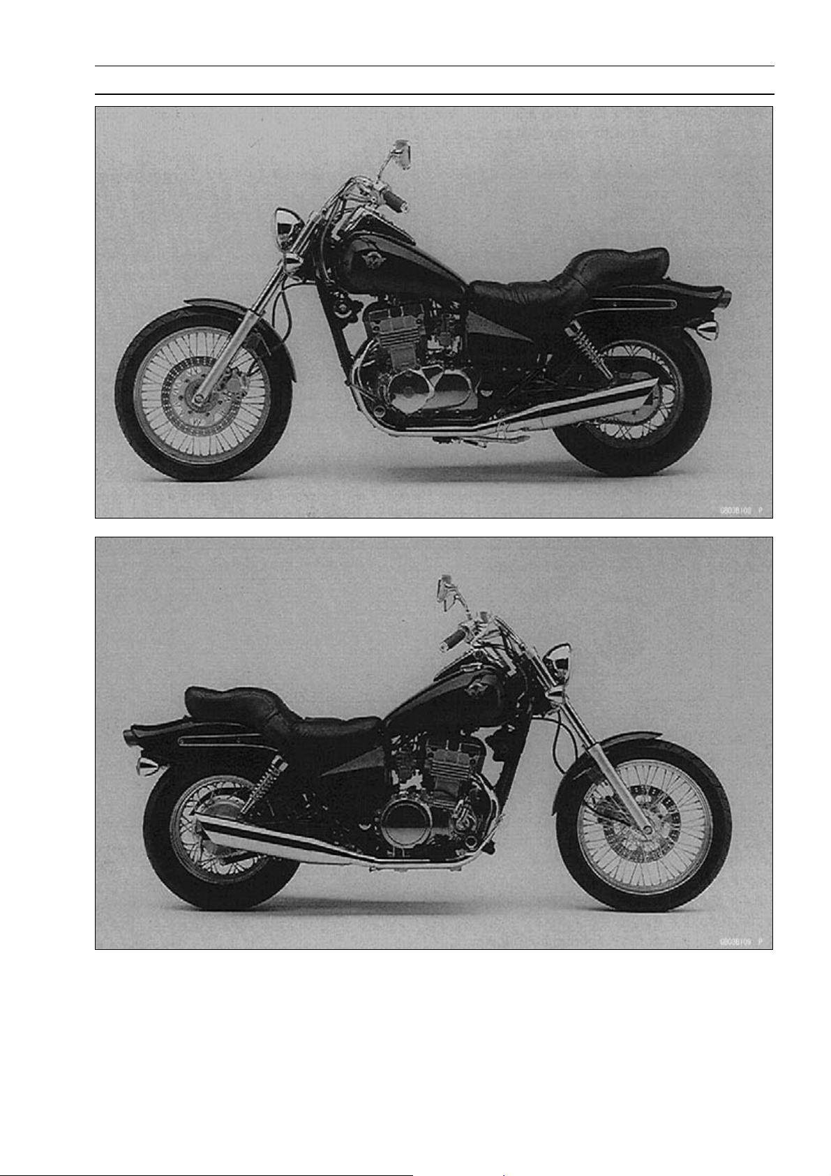
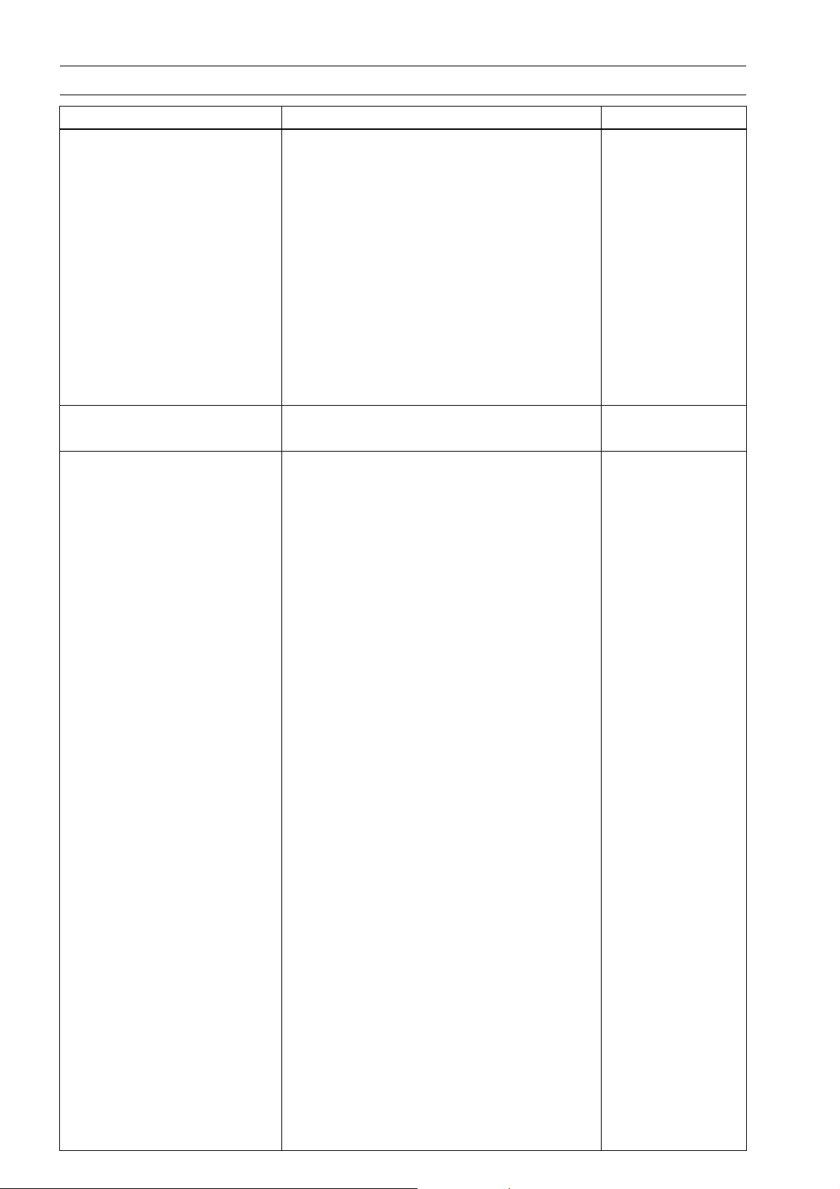
EN500
VULCAN 500 LTD
Motorcycle
Service Manual
Page 2

Page 3
Quick Reference Guide
j
j
j
j
j
j
j
j
j
j
j
j
j
j
j
j
General Information 1
Fuel System 2
Cooling System 3
Engine Top End 4
Clutch 5
Engine Lubrication System 6
Engine Removal/Installation 7
Crankshaft/Transmission 8
This quick reference guide will assist
you in locating a desired topic or procedure.
•Bend the pages back to match the
black tab of the desired chapter number with the black tab on the edge at
each table of contents page.
•Refer to the sectional table of contents
for the exact pages to locate the specific topic required.
Wheels/Tires 9
Final Drive 10
Brakes 11
Suspension 12
Steering 13
Frame 14
Electrical System 15
Appendix 16
Page 4
LIST OF ABBREVIATIONS
A ampere(s) lb pound(s)
ABDC after bottom dead center m meter(s)
AC alternating current min minute(s)
ATDC after top dead center N newton(s)
BBDC before bottom dead center Pa pascal(s)
BDC bottom dead center PS horsepower
BTDC before top dead center psi pound(s) per square inch
°C degree(s) Celsius r revolution
DC direct current rpm revolution(s) per minute
F farad(s) TDC top dead center
°F degree(s) Fahrenheit TIR total indicator reading
ft foot, feet V volt(s)
g gram(s) W watt(s)
h hour(s) Ω ohm(s)
L liter(s)
Read OWNER’S MANUAL before operating.
Page 5

EMISSION CONTROL INFORMATION
To protect the environment in which we all live, Kawasaki has incorporated crankcase emission (1) and exhaust emission (2) control systems in compliance with applicable regulations of
the United States Environmental Protection Agency and California Air Resources Board. Additionally, Kawasaki has incorporated an evaporative emission control system (3) in compliance
with applicable regulations of the California Air Resources Board on vehicles sold in California
only.
1. Crankcase Emission Control System
This system eliminates the release of crankcase vapors into the atmosphere. Instead, the vapors
are routed through an oil separator to the intake side of the engine. While the engine is operating,
the vapors are drawn into combustion chamber, where they are burned along with the fuel and air
supplied by the carburetion system.
2. Exhaust Emission Control System
This system reduces the amount of pollutants discharged into the atmosphere by the exhaust
of this motorcycle. The fuel and ignition systems of t his motorcycle have been carefully des
and constructed to ensure an efficient engine with low exhaust pollutant levels.
3. Evaporative Emission Control System
Vapors caused by fuel evaporation in the fuel system are not vented into the atmosphere. In
stead, fuel vapors are routed into the r unning engine to be burned, or stored in a canister when
the engine is stopped. Liquid fuel is caught by a vapor separator and returned to the fuel tank.
The Clean Air Act, which is the Federal law covering motor vehicle p
commonly referred to as the Act’s “tampering provisions.”
“Sec. 203(a) The following acts and the causing thereof are prohibited...
(3)(A) for any person to remove or r ender inoperative any device or e
on or in a motor vehicle or motor vehicle engine in compliance with regulations under this
title prior to its sale and delivery to the ultimate purchaser, or for any manufacturer or dealer
knowingly to remove or render inoperative any such device or el
sale and delivery to the ultimate purchaser.
(3)(B) for any person engaged in the business of repairing, servicing, selling, leasing, or trading
motor vehicles or motor vehicle engines, or who operates a fle
ingly to remove or render inoperative any device or element of design installed on or in a
motor vehicle or motor vehicle engine in compliance with regulations under this title following its sale and delivery to the ultimate purch
aser...”
ollution, contains what is
lement of design installed
ement of design after such
et of motor vehicles know-
igned
-
NOTE
The phrase “remove or render inoperative any device or element of design” has been generally
○
interpreted as follows:
1. Tampering does not include the temporary removal or rendering inoperative of devices or elements of design in order to perform maintenance.
2. Tampering could include:
a.Maladjustment of vehicle components such that the emission standards are ex-
ceeded.
b.Use of replacement parts or accessories which adversely affect the performance
or dura bility of the motorcycle.
c.Addition of components or accessories that result in the vehicle exceeding the stan-
dards.
d.Permanently removing, disconnecting, or rendering inoperative any component or
element of design of the emission control systems.
WE RECOMMEND THAT ALL DEALERS OBSERVE THESE PROVISIONS OF FEDERAL LAW,
THE VIOLATION OF WHICH IS PUN ISHA BLE BY CIVIL PENALTIES NOT EXCEEDING
$10,000 PER VIOLATION.
Page 6

TAMPERING WITH NOISE CONTROL SYSTEM PROHIBITED
Federal law prohibits the following acts or the causing thereof: (1) The removal or rendering
inoperative by any person other than for purposes of maintenance, repair, or replacement, of any
device or element of design incorporated into any new vehicle for the purpose of noise control
prior to i ts sale or delivery to the ultimate purchaser or while it is in use, or (2) the use of the
vehicle after such device or element of design has been removed or rendered inoperative by
any person.
Among those acts presumed to constitute tampering are the acts listed below:
Replacement of the original exhaust system or muffler with a component not in compliance
•
with Federal regulations.
Removal of the muffler(s) or any internal portion of the muffler(s).
•
Removal of the air box or air box cover.
•
Modifications to the muffler(s) or air intake system by cutting, drilling, or other means if such
•
modifications result in increased noise levels.
Page 7
Foreword
This manual is designed primarily for use by
trained mechanics in a properly equipped shop.
However, it contains enough detail and basic information to make it useful to the owner who desires to perform his own basic maintenance and
repair work. A basic knowledge of mechanics,
the proper use of tools, and workshop procedures must be understood in order to carry out
maintenance and repair satisfactorily. Whenever the owner has insufficient experience or
doubts his ability to do the work, all adjustments, maintenance, and repair should be carried out only by qualified mechanics.
In order to perform the work efficiently and
to avoid costly mistakes, read the text, thoroughly familiarize yourself with the procedures
before starting work, and then do the work ca
fully in a clean area. Whenever special tools or
equipment are specified, do not use makeshift
tools or equipment. Precision measurem
can only be made if the proper instruments are
used, and the use of substitute tools may adversely affect safe operation.
For the duration of the warranty period,
we recommend that all repairs and scheduled
maintenance be performed in
this service manual. Any owner maintenance or
repair procedure not performed in accordance
with this manual may void
To get the longest life out of your vehicle:
Follow the Periodic Maintenance Chart in the
•
Service Manual.
Be alert for problems and non-scheduled
•
maintenance.
Use proper tools and
•
torcycle parts. Special tools, gauges, and
testers that are necessary when servicing
Kawasaki moto
Service Manual. Genuine parts provided as
spare parts are listed in the Parts Catalog.
Follow the p
•
fully. Don’t take shortcuts.
Remember to keep complete records of main-
•
tenance a
parts installed.
rcycles are introduced by the
rocedures in this manual care-
nd repair with dates and any new
genuine Kawasaki Mo-
accordance with
the warranty.
re-
ents
How to Use This Manual
In this manual, the product is divided into its
major systems and these systems make up the
manual’s chapters.
The Quick Reference Guide shows you all
of the product’s system and assists in locating
their chapters. Each chapter in turn has its own
comprehensive Table of Contents.
For example, if you want ignition coil information, use the Quick Reference Guide to locate
the Electrical System chapter. Then, use the
Table of Contents on the first page of the chapter to find the ignition coil section.
Whenever you see these WARNING and
CAUTION symbols, heed their instructions!
Always follow safe operating and maintenance
practices.
WARNING
This warning symbol identifies special
instructions or procedures which, if not
correctly followed, could result in per-
sonal injury, or loss of life.
CAUTION
This caution symbol identifies special
instructions or procedures which, if not
strictly observed, could result in dam-
age to or destruction of equipment.
This manual contains four more symbols (in
addition to WARNING and CAUTION) whi
help you distinguish different types of information.
NOTE
This note symbol indicates points of par-
○
ticular interest for more efficient and con-
venient operation.
Indicates a procedural step or work to be
•
done.
Indicates a procedural sub-step or how to do
○
the work of the procedural step it follows. It
also precedes the te
Indicates a conditional step or w hat action to
take based on the results of the test or inspec-
tion in the proced
lows.
In most chapters an exploded view illustration
of the system com
Contents. In these illustrations you will find the
instructions indicating which parts require specified tighten
agent during assembly.
ing torque, oil, grease or a locking
xt of a NOTE.
ural step or sub-step it fol-
ponents follows the Table of
ch will
Page 8

Page 9

GENERAL INFORMATION 1-1
General I nformation
Table of Con tents
Before Servicing ..................................................................................................................... 1-2
Model Identification................................................................................................................. 1-5
General Specifications (EN500-C1 ∼ C6F Models) ................................................................ 1-6
General Specifications (EN500C7F Model ∼)......................................................................... 1-9
Periodic Maintenance Chart ................................................................................................... 1-12
Torque and Locking Agent...................................................................................................... 1-16
Unit Conversion Table ............................................................................................................ 1-21
1
Page 10

1-2 GENERAL INFORMATION
Before Servicing
Before starting to perform an inspection service or carry out a disassembly and reassembly operation on a motorcycle, read the precautions given below. To facilitate actual operations, notes, illustrations, photographs, cautions, and detailed descriptions have been included in each chapter wherever
necessary. This section explains the items that require particular attention during the removal and
reinstallation or disassembly and reassembly of general parts.
Especially note the following
(1) Dirt
Before removal and disassembly, clean the motorcycle. Any dirt entering the engine will shorten
the life of the motorcycle. For the same reason, before installing a new part, clean off any dust or
metal filings.
(2) Battery Ground
Disconnect the ground (–) cable from the battery before performing any disassembly operations
on the motorcycle. This prevents the engine from accidentally turning over while work is being
carried out, sparks from being generated while disconnecting the cables from electrical parts, as
well as damage to the electrical parts themselves. For reinstallation, first connect the positive
cable to the positive (+) terminal of the battery
(3) Installation, Assembly
Generally, installation or assembly is the reverse of removal or disassembly. However, if installation or assembly sequence is given in this Service Manual, follow it. Note parts locations and
cable, wire, and hose routing during removal or disassembly so they can be installed or assembled in the same way. It is preferable to mark and record the locations and routing whenever
possible.
(4) Tightening Sequence
When installing bolts, nuts, or screws for which a tightening sequence is given in this Service
Manual, make sure to follow the sequence. When installing a part with several bolts, nuts, or
screws, start them all in their holes and tighten them to a snug fit, thus ensuring that the part has
been installed in its proper location. Then, tighten them to the specified torque in the tightening
sequence and method indicated. If tightening sequence instructions are not given, tighten them
evenly in a cross pattern. Conversely, to remove a part, first loosen all the bolts, nuts, or screws
that are retaining the part a 1/4-turn before removing them.
(5) Torque
When torque values are given in this Service Manual, use them. Either too little or too much
torque may lead to serious damage. Use a good quality, reliable torque wrench.
(6) Force
Common sense should dictate how much force is necessary in assembly and disassembly. If
a part seems especially difficult to remove or install, stop and examine what may be causing the
problem. Whenever tapping is necessary, tap lightly using a wooden or plastic-faced mallet. Use
an impact driver for screws (particularly for the removing screws held by non-permanent locking
agent) in order to avoid damaging the screw heads.
(7) Edges
Watch for sharp edges, as they could cause injury through careless handling, especially during
major engine disassembly and assembly. Use a clean piece of thick cloth w hen lifting the engine
or turning it over.
(8) High-Flash Point Solvent
A high-flash point solvent is recommended to reduce fire danger. A commercial solvent commonly available in North America is standard solvent (generic name). Always follow manufacturer
and container directions regarding the use of any solvent.
(9) Gasket, O-ring
Replace a gasket or an O-ring with a new part when disassembling. Remove any foreign matter
from the mating surface of the gasket or O-ring to ensure a perfectly smooth surface to prevent
oil or compression leaks.
Page 11

GENERAL INFORMATION 1-3
Before Servicing
(10)Liquid Gasket, Locking Agent
Clean and prepare surfaces where liquid gasket or non-permanent locking agent will be used.
Apply them sparingly. Excessive amount may block engine oil passages and cause serious damage.
(11)Press
When using a press or driver to install a part such as a wheel bearing, apply a small amount of
oil to the area where the two parts come in contact to ensure a smooth fit.
(12)Ball Bearing and Needle Bearing
Do not remove a ball bearing or a needle bearing unless it is absolutely necessary. Replace any
ball or needle bearings that were removed with new ones. Install bearings with the m anufacturer
and size marks facing out, applying pressure evenly with a suitable driver. Apply force only to the
end of the race that contacts the press fit portion, and press it evenly over the base component.
(13)Oil Seal and Grease Seal
Replace any oil or grease seals that were removed with new ones, as removal generally damages seals. Oil or grease seals should be pressed into place using a suitable driver, applying a
force uniformly to the end of seal until the face of the seal is even with the end of the hole, unless
instructed otherwise. When pressing in an oil or grease seal which has manufacturer’s m arks,
press it in with the marks facing out.
(14)Circlip, Retaining Ring, and Cotter Pin
When installing circlips and retaining rings, take care to compress or expand them only enough
to install them and no more. Install the circlip with its chamfered side facing load side as well.
Replace any circlips, retaining rings, and cotter pins that were removed with new ones, as removal weakens and deforms them. If old ones are reused, they could become detached while
the motorcycle is driven, leading to a major problem.
(15)Lubrication
Engine wear is generally at its maximum while the engine is warming up and before all the sliding
surfaces have an adequate lubricative film. During assembly, make sure to apply oil to any sliding
surface or bearing that has been cleaned. Old grease or dirty oil could have lost its lubricative
quality and may contain foreign particles that act as abrasives; therefore, make sure to wipe it off
and apply fresh grease or oil. Some oils and greases in particular should be used only in certain
applications and may be harmful if used in an application for which they are not intended.
(16)Direction of Engine Rotation
To rotate the crankshaft manually, make sure to do so in the direction of positive rotation. Positive rotation is counterclockwise as viewed from the left side of the engine. To carry out proper
adjustment, it is furthermore necessary to rotate the engine in the direction of positive rotation as
well.
(17)Replacement Parts
When there is a replacement instruction, replace these parts with new ones every time they are
removed.
Replacement parts will be damaged or lose their original function once they are removed. Therefore, always replace these parts with new ones every time they are removed. Although the previously mentioned gasket, O-ring, ball bearing, needle bearing, grease seal, oil seal, circlip, and
cotter pin have not been so designated in their respective text, they are replacement parts.
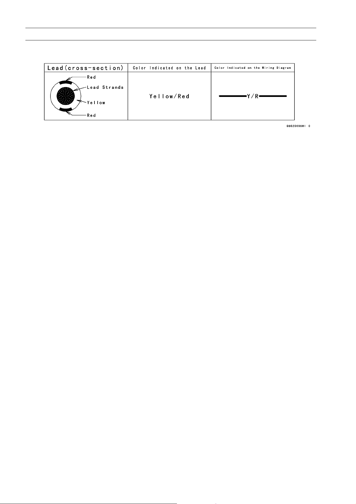
(18)Electrical Leads
All the electrical leads are either one-color or two-color. A two-color lead is identified first by
the primary color and then the stripe color. For example, a yellow lead with thin red stripes is
referred to as a “yellow/red” lead; it would be a “red/yellow” lead if the colors were reversed.
Unless instructed otherwise, electrical leads must be connected to leads of the s ame color.
Page 12
1-4 GENERAL INFORMATION
Before Servicing
Two-Color Electrical
(19)Inspection
When parts have been disassembled, visually inspect these parts for the following conditions
or other damage. If there is any doubt as to the condition of them, replace them with new ones.
Abrasion Crack Hardening Warp
Bent Dent Scratch Wear
Color change Deterioration Seizure
(20)Specifications
Specification terms are defined as follows:
“Standards” show dimensions or performances which brand-new parts or systems have.
“Service Limits” indicate the usable limits. If the measurement shows excessive wear or deteri-
orated performance, replace the dam aged parts.
Page 13
Model Identification
GENERAL INFORMATION 1-5
Page 14
1-6 GENERAL INFORMATION
General Specifications (EN500-C1 ∼ C6F Models)
Items EN500-C1 ∼ C5 EN500-C6 ∼ C6F
Dimensions
Overall Length 2 320 mm (91.3 in.) ←
Overall Width 830 mm (32.7 in.) ←
Overall Height 1 125 mm (44.3 in.) ←
Wheelbase 1 595 mm (62.8 in.) ←
Road Clearance 120 mm (4.92 in.) ←
Seat Height 715 mm (31.5 in.) ←
Dry Weight 199 kg (438 lb) (CAL) 199.5 kg (440 lb) ←
Curb Weight:
Front 95 kg (209 lb) ←
Rear 119 kg (262 lb) (CAL) 119.5 (263 lb) ←
Fuel Tank C apacity 15.0 L (3.9 US gal) ←
Performance
Minimum Turning Radius 2.8 m (9.2 ft) ←
Engine
Type
Cooling System
Bore And Stroke 74.0 × 58.0 mm (2.9 × 2.3 in.)
Displacement 498 cm³ (30.4 cu in.) ←
Compression Ratio 10.2 ←
Maximum Horsepower 34 kW (46 PS) @8 000 r/min (rpm),
Maximum Torque 45 N·m (4.6 kgf·m, 33 ft·lb)
Carburetion System Carburetors, Keihin CVK32 × 2 ←
Starting System Electric starter ←
Ignition System Battery and coil (transistorized) ←
Timing Advance Electronically advanced ←
Ignition Timing
Spark Plugs NGK DR9EA or ND X27ESR-U
Cylinder Numbering M ethod Left to right, 1-2 ←
Firing Order 1-2 ←
Valve Timing:
Inlet:
Open 27° BTDC ←
Close 47° ABDC ←
Duration 254° ←
Exhaust:
Open 52° BBDC ←
Close 22° ATDC ←
4-stroke, DOHC, 2-cylinder
Liquid-cooled ←
(CH, DE) 25 kw (34 PS) @7 000 r/min (rpm),
(FR) 33 kw (45 PS) @8 000 r/min (rpm)
(US) –
@6 000 r/min (rpm),
(CH, DE) 39 N·m (4.0 kgf·m, 29 ft·lb)
@4 200 r/min (rpm), (US) –
From 10° BTDC @1 300 r/min (rpm) to
35° B TDC @8 000 r/min (rpm)
or NGK DR8EA or ND X24ESR-U
←
←
←
←
←
←
Page 15

GENERAL INFORMATION 1-7
General Specifications (EN500-C1 ∼ C6F Models)
Items EN500-C1 ∼ C5 EN500-C6 ∼ C6F
Duration 254° ←
Lubrication System Forced lubrication (wet sump) ←
Engine Oil:
Grade SE, SF or SG class API SE, SF or SG
API SH or SJ with
JASO MA
Viscosity SAE10W-40, 10W-50, 20W-40, or 20W-50 SAE10W-40
Capacity 3.4 L (3.59 US qt) ←
Drive Train
Primary Reduction System:
Type Chain ←
Reduction Ratio 2.652 (61/23) ←
Clutch Type Wet multi disc ←
Transmission
Type
Gear Ratios:
1st 2.571 (36/14) ←
2nd 1.722 (31/18) ←
3rd 1.333 (28/21) ←
4th 1.125 (27/24) ←
5th 0.961 (25/26) ←
6th 0.851 (23/27) ←
Final drive system
Type Chain drive ←
Reduction Ratio 2.625 (42/16) ←
Overall Drive Ratio 5.930 @ Top gear ←
Frame
Type Tubular, double cradle ←
Caster (Rake Angle) 33° ←
Trail 151 mm (5.9 in.) ←
Rim Size:
Front 19 MC × MT 2.15 ←
Rear 15 MC × MT 3.00 ←
Front Tire:
Type Tube ←
Size 100/90-19 57S ← (C6 ∼ C7)
Rear Tire:
Type Tube ←
Size 140/90-15 M /C 70S ←
Front Suspension:
Type Telescopic fork ←
Wheel Travel 150 mm (5.9 in.) ←
6-speed constant mesh, return shift
100/90-19 M/C
57S (C8 ∼)
←
Page 16

1-8 GENERAL INFORMATION
General Specifications (EN500-C1 ∼ C6F Models)
Items EN500-C1 ∼ C5 EN500-C6 ∼ C6F
Rear Suspension:
Type Swing arm ←
Wheel Travel 100 mm (3.9 in.) ←
Brake Type:
Front Single disc ←
Rear Drum ←
Electrical Equipment
Battery 12 V 12 Ah ←
Headlight:
Type Semi-sealed beam ←
Bulb 12 V 60/55 W (quartz-halogen) ←
Tail/brake Light 12 V 8/27 W
(AT, CH, EUR, DE, FR, GR, IT, KR, NL, NO,
ES, SE, GB)
12 V 5/21 W
Alternator:
Type Three-phase AC ←
Rated Output 17 A @6 000 r/min (rpm), 14 V ←
12 V 5/21 W
Specifications subject to change without notice, and may not apply to every country.
AT: Austria Model
CA: Canada Model
CAL: California Model
CH: Switzerland Model
DE: Germany Model
ES: Spain Model
EUR: E u rope Model
FR: France Model
GB: United Kingdom Model
GR: Greece Model
IT: Italy Model
KR: Korea Model
NL: Netherlands Model
NO: Norway Model
SE: Sweden Model
US: United States Model
Page 17
GENERAL INFORMATION 1-9
General Specifications (EN500C7F Model ∼)
Items EN500C7F ∼
Dimensions
Overall Length 2 320 mm (91.3 in.)
Overall Width 830 mm (32.7 in.)
Overall Height 1 125 mm (44.3 in.)
Wheelbase 1 595 m m (62.8 in.)
Road Clearance 120 mm (4.92 in.)
Seat Height 715 mm (31.5 in.)
Dry Weight 199 kg (438 lb) (CAL) 199.5 kg (440 lb)
Curb Weight:
Front 95 kg (209 lb)
Rear 119 kg (262 lb) (CAL) 119.5 (263 lb)
Fuel Tank Capacity 15.0 L (3.9 US gal)
Performance
Minimum Turning Radius 2.8 m (9.2 ft)
Engine
Type 4-stroke, DOHC, 2-cylinder
Cooling System Liquid-cooled
Bore And Stroke 74.0 × 58.0 mm (2.9 × 2.3 in.)
Displacement 498 cm³ (30.4 cu in.)
Compression Ratio
Maximum Horsepower
Maximum Torque 45 N·m (4.6 kgf·m, 33 ft·lb)
Carburetion System Carburetors, Keihin CVK 32 × 2
Starting System Electric starter
Ignition System Battery and coil (transistorized)
Timing Advance Electronically advanced
Ignition Timing
Spark Plugs NGK DR9EA or ND X27ESR-U
Cylinder Numbering Method Left to right, 1-2
Firing Order 1-2
V alve Timing:
Inlet:
Open 27° BTDC
Close 47° ABDC
Duration
Exhaust:
Open 52° BBDC
Close 22° ATDC
Duration 254°
10.2
34 kW (46 PS) @8 000 r/min (rpm),
(US) –
@6 000 r/min (rpm),
From 10° BTDC @1 300 r/min (rpm) to
35° BTDC @8 000 r/min (rpm)
or NGK DR8EA or ND X24ESR-U
254°
Page 18

1-10 GENERAL INFORMATION
General Specifications (EN500C7F Model ∼)
Items EN500C7F ∼
Lubrication System Forced lubrication (wet sump)
Engine Oil:
Grade API SE, SF or SG class
API SH, SJ or SL with JASO MA
Viscosity
Capacity 3.4L(3.59USqt)
Drive Train
Primary Reduction System:
Type Chain
Reduction Ratio 2.652 (61/23)
Clutch Type Wet multi disc
Transmission
Type 6-speed constant mesh, return shift
Gear Ratios:
1st 2.571 (36/14)
2nd
3rd
4th
5th 0.961 (25/26)
6th 0.851 (23/27)
Final drive system
Type Chain drive
Reduction Ratio 2.625 (42/16)
Overall Drive Ratio 5.930 @ Top gear
Frame
Type Tubular, double cradle
Caster (Rake Angle) 33°
Trail 151 mm (5.9 in.)
Rim Size:
Front 19 MC × MT 2.15
Rear 15 MC × MT 3.00
Front Tire:
Type Tube
Size 100/90-19 M/C 57S
Rear Tire:
Type Tube
Size 140/90-15 M/C 70S
Front Suspension:
Type Telescopic fork
Wheel Travel 150 mm (5.9 in.)
Rear Suspension:
Type Swing arm
Wheel Travel 100 mm (3.9 in.)
SAE10W-40
1.722 (31/18)
1.333 (28/21)
1.125 (27/24)
Page 19
GENERAL INFORMATION 1-11
General Specifications (EN500C7F Model ∼)
Items EN500C7F ∼
Brake Type:
Front
Rear Drum
Electrical Equipment
Battery 12 V 12 Ah
Headlight:
Type Semi-sealed beam
Bulb 12 V 60/55 W (quartz-halogen)
Tail/brake Light 12 V 5/21 W
Alternator:
Type Three-phase AC
Rated Output 17 A @6 000 r/min (rpm), 14 V
Specifications subject to change without notice, and may not apply to every country.
CA: Canada Model
CAL: California Model
US: United States Model
Single disc
Page 20

1-12 GENERAL INFORMATION
Periodic Maintenance Chart
The scheduled maintenance m ust be done in accordance with this chart to keep the motorcycle in
good running condition. The initial maintenance is vitally important and must not be neglected.
( Other than United States and Canada Models)
FREQUENCY Whichever
comes
first
OPERATION
Carburetor synchronization - inspect †
Idle speed - adjust †
Throttle grip play - inspect †
Spark plug - clean and gap †
Valve clearance - inspect †
Air suction valve - inspect †
Air cleaner element - clean † #
Fuel hose, connections - inspect †
Battery electrolyte level - inspect † 6 month
Brake play - inspect †
Brake light switch - inspect †
Brake lining or pad wear - inspect †#
Brake fluid level - inspect † month
Brake fluid - change † 2 years
Brake hose, connections - inspect †
Brake master cylinder cup and dust
seal - replace
Caliper fluid seal and dust seal - replace 4 years
Every
4 years
*ODOMETER
READING
× 1 000 km
(× 1 000 mile)
1 6 12 18 24 30 36
(0.6) (4.0) (7.5) (12) (15) (20) (24)
• • •
• • • •
• • • •
• • • • • •
•
• • • • • •
• • •
• • • • • •
• • • • • •
• • • • • • •
• • • • • • •
• • • • • •
• • • • • • •
•
• • • • • •
Brake cable - replace 2 years
Clutch - adjust
Steering - inspect †
Drive chain wear - inspect †#
Drive chain - lubricate # 600 km
Drive chain slack - i nspect †# 1000 km
Spoke tightness and rim runout inspect †
Nut, bolts, and fasteners tightness inspect †
Tire wear - inspect †
Engine oil - change # 6 month
Oil filter - replace
General lubrication - perform #
Front fork oil - change 2 years
Front fork oil leak - inspect †
•
• • • • • • •
• • • • • • •
• • • • • •
• • • • • •
• • • • • • •
• • • • • • •
• • • •
• • • • • •
• • • • • • •
• • • •
• • •
•
• • •
Page 21
Periodic Maintenance Chart
GENERAL INFORMATION 1-13
FREQUENCY Whichever
comes
first
1 6 12 18 24 30 36
OPERATION Every (0.6) (4.0) (7.5) (12) (15) (20) (24)
Swingarm pivot - lubricate
Radiator hoses, connections - inspect †
Coolant - change 2 years
Coolant filter - clean year
Steering stem bearing - lubricate 2 years
Rear shock absorber oil leak - inspect †
#: Service more frequently when operating in severe conditions dusty, wet, muddy, high speed, or
frequent starting/stopping.
†: Replace, add, adjust, clean, or torque if necessary.
*: For higher odometer readings, repeat at the frequency interval established here.
•
• • •
• • •
• • •
*ODOMETER
READING
× 1 000 km
(× 1 000 mile)
•
•
Page 22

1-14 GENERAL INFORMATION
Periodic Maintenance Chart
(United States and Canada Models)
FREQUENCY
OPERATION Every (0.5) (3.1) (6.2) (9.3) (12) (16) (20)
Carburetor synchronization - inspect †
Idle speed - adjust †
Throttle grip play - inspect †
Spark plug - clean and gap †
Valve clearance - inspect †
Air suction valve - inspect †
Air cleaner element - clean
Air c leaner element - replace 5 cleaning
Fuel system - inspect
Fuel hose, connections - inspect †
Evaporative emission control system (CAL) inspect
Whichever
comes
first
0.8 5 10 15 20 25 30
• • • • • • •
• • • • • • •
• • • •
• • • • • •
• • • •
• • • • • •
• • • •
• • •
• • • • • •
• • • • • • •
*ODOMETER
READING
× 1 000 km
(× 1 000 mile)
•
Radiator Hoses, connections - inspect † year
Drive chain - lubricate # 600 km
Drive chain slack - inspect †# 1 000 km
Spoke tightness and rim runout - inspect †
Rim runout - inspect †
Fuel hose-replace 4 years
Brake hose-replace 4 years
Battery electrolyte level - inspect † m onth
Brake play - inspect †
Brake light switch - inspect †
Brake lining or pad wear - inspect †
Brake fluid level - inspect † month
Brake fluid - change † 2 years
Brake hose, connections - inspect †
Brake master cylinder cup and dust seal replace
Caliper fluid seal and dust seal - replace 2 years
Brake cable - replace 2 years
2 years
• • • •
• • • • • • •
• • • • • • •
• • • • • • •
• • • • • • •
• • • • • • •
• • • • • •
• • • • • • •
•
• • • • • •
Brake camshaft - lubricate 2 years
Clutch - adjust
Steering - inspect †
Drive chain wear - inspect †#
Nut, bolts, and fasteners tightness - inspect †
Tire wear - inspect †
•
• • • • • • •
• • • • • • •
• • • • • •
• • • •
• • • • • •
Page 23
Periodic Maintenance Chart
GENERAL INFORMATION 1-15
FREQUENCY
OPERATION Every (0.5) (3.1) (6.2) (9.3) (12) (16) (20)
Engine oil - change year
Oil filter - replace
General lubrication - perform #
Front fork oil - change
Swingarm pivot - lubricate
Coolant - change 2years
Coolant filter - clean year
Steering stem bearing - lubricate 2years
#: Service more frequently when operating in severe conditions dusty, wet, muddy, high speed, or
frequent starting/stopping.
†: Replace, add, adjust, clean, or torque if necessary.
*: For higher odometer readings, repeat at the frequency interval established here.
CAL: California Model
Whichever
comes
first
0.8 5 10 15 20 25 30
• • • •
• • • •
• • • • • •
• • •
• • •
*ODOMETER
READING
× 1 000 km
(× 1 000 mile)
•
•
•
Page 24
1-16 GENERAL INFORMATION
Torque and Locking Agent
Tighten all bolts and nuts to the proper torque using an accurate torque wrench. An insufficiently
tightened bolt or nut may become damaged or fall off, possibly resulting in damage to the motorcycle
and injury to the rider. A bolt or nut which is overtightened may become damaged, strip an internal
thread, or break and then fall out. The following table lists the tightening torque for the major bolts
and nuts, and the parts requiring use of a non-permanent locking agent or liquid gasket.
When checking the tightening torque of the bolts and nuts, first loosen the bolt or nut by half a turn
and then tighten it to the specified torque.
Letters used in the “Remarks” column mean:
L: Apply a non-permanent locking agent to the threads.
Lh: Left-hand threads.
LG: Apply liquid gasket to the threads.
S: Tighten the fasteners following the specified sequence.
SS: Apply silicone sealant to the threads.
Fastener
Fuel System
Fuel Tap Mounting Bolts
Cooling System
Radiator Hose Clamp Screws
Radiator Fan Switch
Thermostat Housing Bolts 11 1.1 95 in·lb
Water Temperature Switch 7.8 0.8 69 in·lb SS
Water Pump Cover Bolts 11 1.1 95 in·lb
Water Pump Shaft 25 2.5 18 Lh
Water Pump Impeller 9.8 1.0 87 in·lb Lh
Water Pipe Screws 4.9 0.5 43 in·lb
Coolant Passage Blank Caps 9.8 1.0 87 in·lb L
Coolant Drain Plug 11 1.1 95 in·lb
Engine Top End
Air Suction Valve Cap Bolts 11 1.1 95 in·lb
Cylinder Head Cover Bolts 9.8 1.0 87 in·lb
Camshaft Cap Bolts 12 1.2 104 in·lb S
Rocker Shafts 39 4.0 29
Valve Adjuster Locknuts 25 2.5 18
Camshaft Sprocket Bolts 15 1.5 11 L
Cylinder Head Bolts (M10) 51 5.2 38 S
Cylinder Head Bolts (M6) 9.8 1.0 87 in·lb S
Cam Chain Tensioner Mounting Bolts 11 1.1 95 in·lb
Cam C hain Tensioner Cap Bolt 4.9 0.5 43 in·lb
Main Oil Pipe Upper Banjo Bolts M8 12 1.2 104 in·lb
Main Oil Pipe Lower Banjo Bolt M10 20 2.0 14.5
Oil Pipe Bolts (in the cylinder head) 11 1.1 95 in·lb
Oil Pipe Mounting Bolt
N·m kgf·m ft·lb
4.9 0.5 43 in·lb with black
2.5 0.25 22 in·lb with white
2.5 0.25 22 in·lb
18 1.8 13
11 1.1 95 in·lb
Torque
Remarks
washer
washer
Page 25
Torque and Locking Agent
GENERAL INFORMATION 1-17
Fastener
Clutch
Oil Filler Plug
Clutch Hub Nut
Clutch Spring Bolts 9.3 0.95 82 in·lb
Clutch Cable Holder Bolt 11 1.1 95 in·lb
Clutch Cover Bolts 11 1.1 95 in·lb
Clutch Cover Damper Plate Bolts 9.8 1.0 87 in·lb L
Engine Lubrication System
Oil Passage Plug 18 1.8 13
Oil Filter Mounting Stud 25 2.5 18 L
Oil Filter (Cartridge Type) 17 1.75 12.5
Oil Pipe for Balancer Shaft Banjo B olt 20 2.0 14.5
Oil Pipe for Drive Shaft Upper Banjo Bolt M6 7.8 0.80 69 in·lb
Oil Pipe for Drive Shaft Lower Banjo Bolt M8 12 1.2 104 in·lb
Oil Pipe for Output Shaft Upper Banjo Bolt M6 7.8 0.80 69 in·lb
Oil Pipe for Output Shaft Lower Banjo Bolt M8 12 1.2 104 in·lb
Oil Pipe for O utput Shaft Mounting Bolt 11 1.1 95 in·lb L
Oil Pump Outer Oil Pipe Bolt 11 1.1 95 in·lb L
Oil Pum p Mounting Bolts 11 1.1 95 in·lb L
Relief Valve 15 1.5 11 L
Oil Pressure Switch 15 1.5 11 SS
Engine Oil D rain Plug 29 3.0 22
Oil Pan Mounting Bolts 11 1.1 95 in·lb
Breather Body Bolt 5.9 0.6 52 in·lb
Engine Removal/Installation
Engine Mounting Nuts 44 4.5 33
Engine Mounting Bracket Nuts 25 2.5 18
Engine Mounting Bracket Bolts 25 2.5 18
Crankshaft/Transmission
Crankcase Bolts (M8) 27 2.8 20 S
Crankcase Bolts (M6) 12 1.2 104 in·lb S
Upper Primary Chain Guide Mounting Nut 11 1.1 95 in·lb L
Lower Primary Chain Guide Mounting Bolt 11 1.1 95 in·lb L
Connecting Rod Big End Cap Nuts 36 3.7 27
Return Spring Pin 20 2.0 14.5 L
Gear Positioning Lever Pivot Stud – – – L
Gear Positioning Lever Nut 11 1.1 95 in·lb
Shift Lever Clamp Bolts 11 1.1 95 in·lb
Shift Linkage Rod Lock Nuts 11 1.1 95 in·lb Lh (1)
Shift Pedal Mounting Bolt 8.8 0.9 78 in·lb
Shift Drum Bearing Holder Bolts 11 1.1 95 in·lb L
N·m kgf·m ft·lb
1.5 0.15 13 in·lb
132 13.5 98
Torque
Remarks
(planted side)
(planted side)
Page 26

1-18 GENERAL INFORMATION
Torque and Locking Agent
Fastener
Shift Drum Cam Pin Plate Screw – – – L
Shift R od Stopper Bolt 11 1.1 95 in·lb
External Shift Mechanism Cover Bolts 11 1.1 95 in·lb
Neutral Switch 15 1.5 11
Wheels/Tires
Front Axle Nut 88 9.0 65
Front Axle Clamp Allen Bolt 34 3.5 25
Rear Axle Nut 88 9.0 65
Spoke Nipples
Torque Link Nuts 34 3.5 25
Final Drive
Engine Sprocket Nut 127 13 94
Rear Sprocket Nuts 74 7.5 54
Rear Coupling Studs – – –
Drive Chain Guide Bolts 11 1.1 95 in·lb
Brakes
Brake Hose Banjo Bolts 25 2.5 18
Reservoir Cap Screws 1.5 0.15 13 in·lb
Brake Lever Pivot Bolt 1.0 0.1 9in·lb
Brake Lever Pivot Locknut 5.9 0.6 52 in·lb
Master Cylinder Clamp Bolts 11 1.1 95 in·lb S
Front Brake Light Switch Mounting Screw
Caliper M ounting Bolts
Caliper Bleed Valves
Brake Disc Mounting Bolts 27 2.8 20 L
Brake Pedal Mounting Bolt 25 2.5 18
Torque Link Nuts 34 3.5 25
Brake Cam Lever Bolt
Suspension
Front Fork Top Plug 23 2.3 16.5
Front Fork Upper Clamp Allen Bolts 20 2.0 14.5
Front Fork Lower Clamp Allen Bolts 29 3.0 22
Front Fork Bottom Allen Bolt 29 3.0 22 L
Rear Shock Absorber Upper Mounting Bolt 25 2.5 18
Rear Shock Absorber Lower Mounting Bolt 34 3.5 25
Swingarm Pivot Nut 88 9.0 65
Steering
Handlebar Mounting Nuts 34 3.5 25
Steering Stem Head Bolt 44 4.5 33
N·m kgf·m ft·lb
5.2 0.53 46 in·lb
59 6.0 43 (Self Locknut)
1.2 0.12 10 in·lb
34 3.5 25
7.8 0.8 69 in·lb
19 1.9 14
Torque
(planted side)
Remarks
L
Page 27
Torque and Locking Agent
GENERAL INFORMATION 1-19
Fastener
Steering S tem Nut
Frame
Side Stand Mounting Bolt 44 4.5 33
Footpeg Holder Bolts (M10) 34 3.5 25
Footpeg Holder Bolts (M12) 54 5.5 39
Muffler Bracket Bolts (M8) 25 2.5 18
Muffler Bracket Bolts (M10) 34 3.5 25
Electrical System
Front Brake Light Switch Mounting Screw 1.2 0.12 10 in·lb
Crankshaft Sensor Mounting Allen Bolts 8.3 0.85 74 in·lb L
Timing Inspection Plug 2.5 0.25 22 in·lb
Alternator Rotor Bolt Plug 1.5 0.15 13 in·lb
Alternator Cover Bolts 11 1.1 95 in·lb
Alternator Cover Allen Bolt 13 1.3 113 in·lb
Alternator Lead Clamp Screws 2.9 0.30 26 in·lb
Spark Plug 14 1.4 10
Alternator Stator Allen Bolts 12 1.2 104 in·lb
Alternator Rotor Bolt 69 7.0 51
Starter Motor Mounting Bolts
Starter Chain Guide Screws
Starter Motor Through Bolts
Starter Motor Terminal Nut 6.9 0.7 65 in·lb
Starter Motor Cable Clamp Nut 4.9 0.5 43 in·lb
Starter Clutch Allen Bolts 34 3.5 25 L
Side Stand Switch Mounting Screw 3.9 0.4 35 in·lb L
Oil Pressure Switch 15 1.5 11
Neutral Switch 15 1.5 11
Tail Light Mounting Nuts 5.9 0.6 52 in·lb
N·m kgf·m ft·lb
Hand
-Tighten
(about
4.9)
11 1.1 95 in·lb
4.9 0.5 43 in·lb L
6.9 0.7 65 in·lb
Torque
Hand
-Tighten
(about
0.5)
Hand
-Tighten
(about 43
in·lb)
Remarks
Page 28
1-20 GENERAL INFORMATION
Torque and Locking Agent
The table relating tightening torque to thread diam eter, lists the basic torque for the bolts and nuts.
Use this table for only the bolts and nuts which do not require a specific torque value. All of the values
are for use with dry solvent-cleaned threads.
General Fasteners
Threads Torque
Diameter (mm) N·m kgf·m ft·lb
5 3.4 ∼ 4.9 0.35 ∼ 0.50 30 ∼ 43 in·lb
6 5.9 ∼ 7.8 0.60 ∼ 0.80 52 ∼ 69 in·lb
8 14 ∼ 19 1.4 ∼ 1.9 10.0 ∼ 13.5
10 25 ∼ 34 2.6 ∼ 3.5 19.0 ∼ 25
12 44 ∼ 61 4.5 ∼ 6.2 33 ∼ 45
14 73 ∼ 98 7.4 ∼ 10.0 54 ∼ 72
16 115 ∼ 155 11.5 ∼ 16.0 83 ∼ 115
18 165 ∼ 225 17.0 ∼ 23.0 125 ∼ 165
20 225 ∼ 325 23 ∼ 33 165 ∼ 240
Page 29
Unit Conversion Table
GENERAL INFORMATION 1-21
Prefixes for Units
Prefix Symbol Power
mega M × 1 000 000
kilo k × 1 000
centi c ×0.01
milli m ×0.001
micro μ × 0.000001
Units of Mass
kg ×2.205=lb
g × 0.03527 = oz
Units of Volume
L × 0.2642 =
L × 0.2200 = gal (imp)
L × 1.057 = qt (US)
L × 0.8799 = qt (imp)
L × 2.113 = pint (US)
L × 1.816 = pint (imp)
mL × 0.03381 = oz (US)
mL × 0.02816 = oz (imp)
mL × 0.06102 = cu in
gal (US)
Units of Length
km × 0.6214 = mile
m × 3.281 =
mm × 0.03937 = in
ft
Units of Torqu e
N·m × 0.1020 = kg·m
N·m × 0.7376 = ft·lb
N·m × 8.851 = in·lb
kgf·m × 9.807 = N·m
kgf·m × 7.233 = ft·lb
kgf·m × 86.80 = in·lb
Units of Pressure
kPa × 0.01020 = kg/cm²
kPa × 0.1450 = psi
kPa × 0.7501 = cmHg
kg/cm² × 98.07 = kPa
kg/cm² × 14.22 = psi
cmHg×1.333=kPa
Units of Speed
km/h × 0.6214 = mph
Units of Force
N × 0.1020 = kg
N × 0.2248 = lb
kg ×9.807=N
kg ×2.205=lb
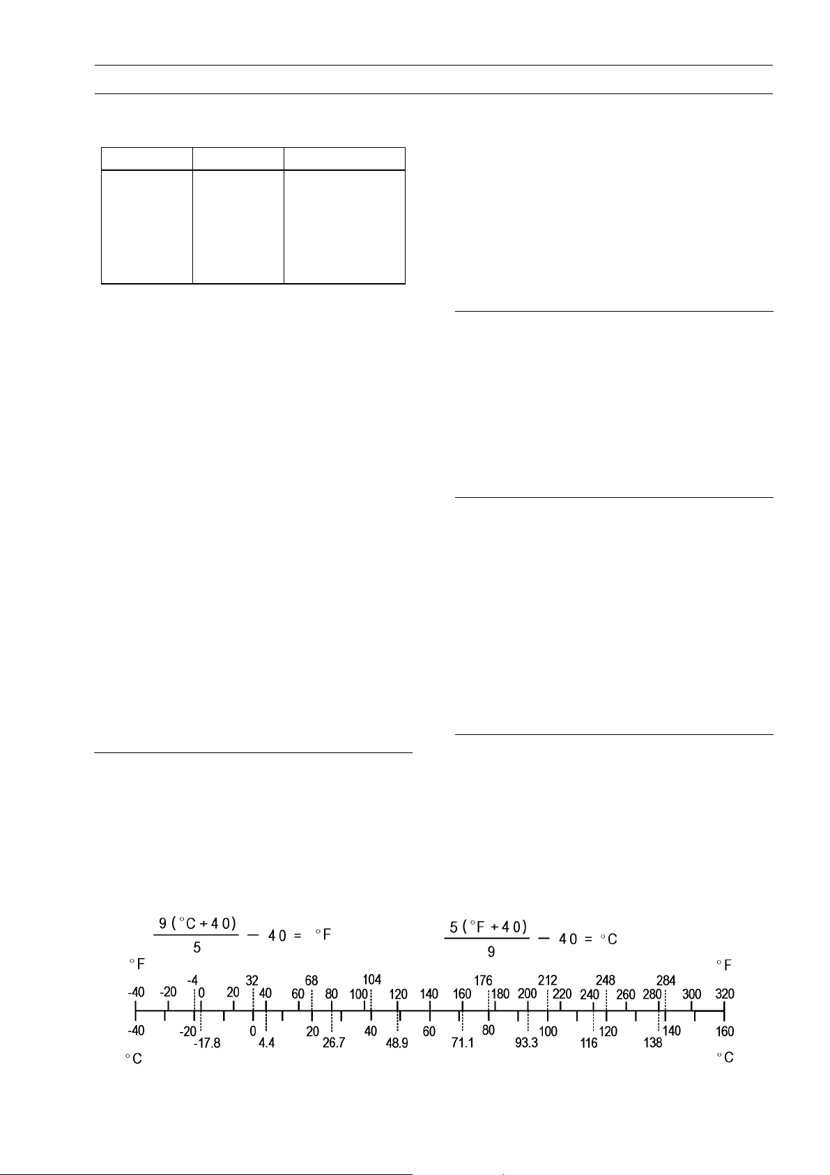
Units of Temperature
Units of Power
kW ×1.360=PS
kW ×1.341=HP
PS × 0.7355 = kW
PS × 0.9863 = HP
Page 30

Page 31

Fuel System
Table of Contents
FUEL SYSTEM 2-1
2
Exploded View................................... 2-2
Specifications .................................... 2-4
Special Tools ..................................... 2-5
Throttle Grip and Cable ..................... 2-6
Throttle Grip Free Play Inspection 2-6
Throttle Cable Adjustment ........... 2-6
Throttle Cable Inspection ............. 2-7
Throttle Cable Lubrication............ 2-7
Carburetors........................................ 2-8
Idle Speed Inspection .................. 2-8
Idle Speed Adjustment................. 2-8
High Altitude Performance
Adjustment (United States
Model) ....................................... 2-8
Vacuum Synchronization
Inspection .................................. 2-8
Synchronization Adjustment ........ 2-9
Service Fuel Level Inspection ...... 2-9
Service Fuel Level Adjustment .... 2-10
Fuel System Cleanliness
Inspection .................................. 2-11
Carburetor Removal..................... 2-11
Carburetor installation.................. 2-12
Carburetor Disassembly/Assem-
bly.............................................. 2-12
Carburetor Separation/Assembly. 2-14
Carburetor Cleaning..................... 2-14
Carburetor Inspection .................. 2-15
Coolant Filter Cleaning (AT,
DE, FR, IT, NL, CH, GB, KR,
Models) ..................................... 2-16
Air Cleaner......................................... 2-17
Air Cleaner Housing Removal...... 2-17
Air Cleaner Housing Installation... 2-17
Air C leaner Element
Removal/Installation .................. 2-17
Air Cleaner Element Cleaning and
Inspection .................................. 2-18
Oil Draining .................................. 2-18
Fuel Tank ........................................... 2-19
Fuel Tank Removal ...................... 2-19
Fuel Tank Installation ................... 2-20
Fuel Tap Removal........................ 2-20
Fuel Tap Installation ..................... 2-20
Fuel Tank and Tap Cleaning ........ 2-20
Fuel Tap Inspection...................... 2-21
Fuel Tank and Cap Inspection ..... 2-21
Evaporative Emission Control System
(California Model only).................... 2-22
Parts Removal/Installation ........... 2-22
Hose Inspection ........................... 2-22
Separator Inspection.................... 2-22
Separator Operation Test............. 2-23
Canister Inspection ...................... 2-23
Page 32

2-2 FUEL SYSTEM
Exploded View
A: Austria, Germany, France, Italy, Korea, Netherlands, Switzerland and United Kingdom Models
Europe Models (EN500-C6 ∼)
B: California Model
CL: Apply cable lubricant.
G: Apply grease.
Page 33

Exploded View
FUEL SYSTEM 2-3
1. Jet Needle
2. Pilot Screw
3. Plug (United St
land Models)
4. Pilot Jet
5. Needle Jet
6. Needle Jet Holder
7. Main Jet
T1: 2.5 N·m (0.
washer)
25 kgf·m, 22 i n·lb) (with white
ates, Canada and Switzer-
4.9 N·m (0.5 kgf·m, 43 in·lb) (with black
washer)
A: United States,
rea and California Models
Canada and Germany Models (EN500
-C2 ∼)
Europe and France Models (EN500-C6 ∼)
B: California Model
C: EN500-C1 ∼ EN5
Switzerland, Austria, Ko-
00C7F Models
Page 34

2-4 FUEL SYSTEM
Specifications
Item
EN500-C1 ∼ C4 EN500-C5 ∼
Throttle Grip and Cables
Throttle Grip Free Play 2 ∼ 3 mm (0.08 ∼ 0.12 in.) ←
Carburetor specifications
Make/Type Keihin/CVK32 ←
Main Jet #102 ←
Main Air Jet #100 ←
Jet Needle N2WE, C1: (AT, CH, US, CAL)
C2 ∼ C4: (AT, CH, US, CAL, CA, DE)
N2WD, C1: (FR, GB, IT, NL, DE, EUR, GR ,
SE, NO, ES, CA)
C2 ∼ C4: (FR, GB, IT, NL, EUR, GR,
SE, NO, ES, KR, ML)
Pilot Jet #35 ←
Pilot Air Jet #150 ←
Pilot Screw 2 1/8 (turns out) ←
Starter Jet #48 ←
Service Fuel Level 0.5 ±1 mm (0.02 ±0.04 in.) ←
(above the bottom edge of carburetor body) ←
Float Height 17.0 ±2.0 mm (0.67 ±0.08 in.) ←
Idle Speed 1 300 ±50 r/min (rpm)
Air Cleaner Element Oil
Grade SE, SF, or SG class ←
Viscosity SAE30 ←
Standard
N2WE (US, CAL,
CA,DE,FR,EUR)
←
AT: Austria Model
CA: Canada Model
CAL: California Model
CH: Switzerland Model
DE: Germany Model
ES: Spain Model
EUR: E u rope Model
FR: France Model
GB: United Kingdom Model
GR: Greece Model
IT: Italy Model
KR: Korea Model
NL: Netherlands Model
NO: Norway Model
SE: Sweden Model
US: United States Model
ML: Malaysia Model
Page 35

Special Tools
FUEL SYSTEM 2-5
Fuel Level Gauge:
57001-1017
Pilot Screw Adjuster, C:
57001-1292
Vacuum Gauge:
57001-1369
Page 36

2-6 FUEL SYSTEM
Throttle Grip and Cable
ThrottleGripFreePlayInspection
Check the throttle grip free play [A].
•
If the free play is incorrect, adjust the throttle cable.
Throttle Grip Free Play
Standard: 2 ∼ 3mm(0.08∼ 0.12 in.)
Check that the throttle grip moves smoothly from full open
•
to close, and the throttle closes quickly and completely in
all steering positions by the return spring.
If the throttle grip does not return properly, check the throttle cable routing, grip free play, and cable damage. Then
lubricate the throttle cable.
Run the engine at the idle speed, and turn the handlebar
•
all the way to the right and left to ensure that the idle speed
does not change.
If the idle speed increase, check the throttle cable free
play and the cable routing.
Throttle Cable Ad justment
Loosen the locknuts [A], and screw both throttle cable ad-
•
justers [B] in fully at the upper end of the throttle cables
so as to give the throttle grip plenty of play.
Turn out the decelerator cable [C] adjuster until there is
•
no clearance between the cable bracket and the stopper
when the throttle grip is completely closed. Tighten the
locknut.
Turn the accelerator cable [D] adjuster until the proper
•
amount of throttle grip free play is obtained. Tighten the
locknut.
If the throttle cables can not be adjusted by using the cable adjusters at the upper end of the throttle cables, use
the cable adjusters at the lower ends of the throttle cables.
First give the throttle grip plenty of play by turning the
•
adjusters at the grip in fully. Tighten the locknuts.
Turn out both upper nuts [A] and turn in both lower nuts [B]
•
as far as they will go so as to give the throttle grip plenty
of play.
With the throttle grip completely closed, turn out the lower
•
nut and turn in the upper nut of the decelerator cable until
the inner cable just becomes tight.
Turn out the lower nut and turn in the upper nut of the
•
accelerator cable until the correct free play is obtained.
Check that the throttle linkage lever stops against the idle
•
adjusting screw with the throttle grip closed.
Start the engine.
•
Turn the handlebar from side to side while idling the en-
•
gine.
If idle speed varies, the throttle cable may be poorly
routed or it m ay be dam aged.
Correct any problem before operating the motorcycle.
•
WARNING
Operation w ith an incorrectly routed or improperly
adjusted cables could result in an unsafe riding
condition.
Page 37

Throttle Grip and Cable
Throttle Cable Inspection
Remove both ends of the throttle cables.
•
With the cable disconnected at both ends, the cable
•
should move freely [A] within the cable housing.
If cable movement is not free after lubricating, if the cable
is frayed [B], or if the cable housing is kinked [C], replace
the cable.
FUEL SYSTEM 2-7
Throttle Cable Lubrication
Whenever the throttle cables are removed, lubricate the
throttle cables as follows:
Apply a thin coating of grease to the throttle cable lower
•
ends [A].
Lubricate the throttle cable with a penetrating rust inhib-
•
iter.
Page 38

2-8 FUEL SYSTEM
Carburetors
Idle Speed Inspection
Start the engine and warm it up thoroughly.
•
With the engine idling, turn the handlebar to both sides.
•
If handlebar movement changes the idle speed, the throttle cable may be improperly adjusted or incorrectly routed,
or it may be damaged. Be sure to correct any of these
conditions before riding.
WARNING
Operation with improperly adjusted, incorrectly
routed, or damaged cables could result in an unsafe riding condition.
Check idle speed.
•
If the idle speed is out of the specified range, adjust it.
Idle Speed
1300±50r/min(rpm)
Idle Speed Adjustment
tart the engine and warm it up thoroughly.
S
•
Turn the adjusting screw [A] until idle speed is correct.
•
Open and close the throttle a few times to make sure that
○
the idle speed is within the specified range. Readjust if
necessary.
High Altitude Performance Adjustment (United States Model)
To i mprove the EMISSION CONTROL PERFORMANCE
○
of vehicle operated above 4 000 feet, Kawasaki recommends the following E nvironmental Protection Agency
(EPA) approved modification.
Change the main jet and pilot jet for high altitude use.
•
High Altitude Carburetor Specifications
Main Jet: #100
Pilot Jet: #32
Vacuum Synchronization Inspection
Situate t he motorcycle so that it is perpendicular to the
•
ground.
Warm up the engine.
•
Check idle speed and adjust if necessary.
•
Pull the vacuum hoses off, and attach vacuum gauge [A]
•
to the vacuum hose fittings [B] on the carburetors.
Special Tool - Vacuum Gauge: 57001-1369
Page 39

Carburetors
Start the engine and let it idle to m easure the carburetor
•
intake vacuum.
If the intake vacuum difference between the two cylinders
exceeds the limit, adjust the synchronization.
Engine Vacuum Synchronization
Less than 2.7 kPa (2 cmHg) difference between both
cylinders
Synchronization Adjustment
Turn the adjusting screw [A] to synchronize the carbure-
•
tor.
If the carburetor synchronization cannot be obtained by
using the adjusting screw, check for dirt or blockage, and
then check the pilot screw settings.
Special Tool - Pilot Screw Adjuster, C: 57001-1292
NOTE
Do not turn the pilot screws carelessly during carburetor
○
synchronization. You may cause poor running at low
engine speed.
FUEL SYSTEM 2-9
Check idle speed and adjust if necessary.
•
Service Fuel Level Inspection
WARNING
Gasoline is extremely flammable and can be explosive under certain conditions. Turn the ignition
switch OFF. Do not sm oke. Make sure the area is
well-ventilated and free from any source of flame
or sparks; this includes any appliance with a pilot
light
Situate the motorcycle so that it is perpendicular to the
•
ground.
Connect a suitable r ubber hose (5 mm inside diameter
•
and about 300 m m long) to the fitting at the bottom of
each carburetor float bow l.
Connect fuel level gauge [A] to the rubber hose.
•
Special Tool - Fuel Level Gauge: 57001-1017
Hold the gauge vertically against the side of the carburetor
•
body so that the “middle” line [B] is several millimeters
higher than the bottom edge [D] of the carburetor body.
Turn the fuel tap to the PRI position to feed fuel to the
•
carburetor, then turn out the carburetor drain plug [C] a
few turns.
Wait until the fuel level [E] in the gauge settles.
•
Page 40

2-10 FUEL SYSTEM
Carburetors
Keeping the gauge vertical, slowly lower the gauge until
•
the “middle” line is even with the bottom edge of the carburetor body.
NOTE
Do not lower the “middle” line below the bottom edge of
○
the carburetor body. If the gauge is lowered and then
raised again, the fuel level measured shows somewhat
higher than the actual fuel level. If the gauge is lowered
too far, dump the fuel out of it into a suitable container
and start the procedure over again.
Read the fuel level in the gauge and compare it to the
•
specification.
Screw in the carburetor drain plug.
•
Service Fuel Level
0.5 ±1 mm (0.02 ±0.04 in.) above the bottom edge of
carburetor body
Turn the fuel tap to the ON position and remove the fuel
•
level gauge.
Inspect the fuel level in another carburetor in the same
•
manner.
If the fuel level is incorrect, adjust it (see Service Fuel
Level Adjustment).
Service Fuel Level Adjustment
WARNING
Gasoline is extremely flammable and can be explosive un der certain conditions. Turn the ignition
switch OFF. Do not smoke. Make sure the area is
well-ventilated and free from any source of flame
or sparks; this includes any appliance with a pilot
light.
Remove the carburetor, and drain the fuel into a suitable
•
container.
Remove the float bowl by taking out the screws with lock-
•
washers.
Slide out the pivot pin [A] and remove the float [B].
•
Bend the tang [A] on the float arm very slightly to change
•
the float height. Increasing the float height lowers the fuel
level and decreasing the float height raises the fuel level.
Float Height
17.0±2.0mm(0.67±0.08in.)
Page 41

Carburetors
NOTE
Do not push the needle rod [A] in during the float height
○
measurement [B].
Assemble the carburetor, and recheck the fuel level.
•
If the fuel level cannot be adjusted by this method, the
float or the float valve [C] is damaged.
Fuel Sys tem Cleanliness Inspection
WARNING
Gasoline is extremely flammable and can be explosive under certain conditions. Turn the ignition
switch OFF. Do not sm oke. Make sure the area is
well-ventilated and free from any source of flame
or sparks; this includes any appliance with a pilot
light.
FUEL SYSTEM 2-11
Connect a suitable hose [A] to the fitting at the bottom of
•
each carburetor float bow l.
Run the lower ends of the hoses into a suitable container.
•
Turn the fuel tap to the PRI position.
•
Turn out each drain plug [B] a few turns and drain the float
•
bowls.
Check to see if water or dirt comes out.
•
If any water or dirt appears during the above inspection,
clean the fuel system (see Carburetor Cleaning and Fuel
Tank Cleaning).
Tighten the drain plugs and turn the f uel tap to the ON
•
position.
Carburetor Removal
WARNING
Gasoline is extremely flammable and can be explosive under certain conditions. Turn the ignition
switch OFF. Do not sm oke. Make sure the area is
well-ventilated and tee from any source of flame
or sparks; this includes any appliance with a pilot
light.
Remove:
•
Side Covers (see Right and Left Side Cover Removal in
the Frame chapter)
Seat (see Seat Removal/Installation in the Frame chapter)
Fuel Tank (see Fuel Tank Removal)
Page 42

2-12 FUEL SYSTEM
Carburetors
Loosen the carburetor clamps [A] and slide back the
•
spring bands [B].
Remove the carburetor from the end of the air cleaner
•
duct, and then pull it out of the carburetor holder.
Remove the carburetor to the left side.
•
Slip the throttle cable lower ends out of the cable bracket.
•
After removing the carburetors, stuff pieces of lint-free,
•
clean cloths into the carburetor holders and the intake
ducts to keep dirt out of the engine and air cleaner.
WARNING
If dirt or dust is allowed to pass through into the
carburetors, the throttle may become stuck, possibly causing an accident.
CAUTION
If dirt gets through into the engine, excessive engine wear and possible engine damage will occur.
Carburetor installation
Installation is the reverse of removal.
•
Check fuel leakage from the carburetors.
•
WARNING
Fuel spilled from the carburetors is hazardous.
Adjust the following items if necessary.
•
Idle Speed
Vacuum Synchronization
Throttle Cables
Carburetor Disassembly/Assembly
Read the WARNINGS in the Carburetor Removal.
•
For the United States and Switzerland models, remove
•
the pilot screw plug as follows:
Punch a hole in the plug and pry it out with an awl or other
○
suitable tool.
Turn in the pilot screw and count the number of turns until
•
it seats fully but not tightly, and then remove the screw.
This is to set the screw to its original position when assembling.
After installing the upper chamber cover, check that the
•
vacuum piston slides up and down smoothly without binding in the carburetor bore.
CAUTION
During carburetor disassembly, be careful not to
damage the diaphragm. Never use a sharp edge to
remove the diaphragm.
Page 43

Carburetors
Turn in the pilot screw [A] fully but not tightly, and then
•
back it out the same number of turns counted during disassembly.
For the United States and Switzerland models, install the
•
pilot screw plug as follows:
Install a new plug [B] in the pilot screw hole [C], and apply
○
a small amount of a bonding agent [D] to the circumference of the plug to fix the plug.
CAUTION
Do not apply too much bond on the plug to keep the
pilot screw itself from being fixed.
Turn the carburetor body upside-down, and drop the nee-
•
dle jet [A] into place so that the smaller diameter end [B]
of the jet goes in first.
FUEL SYSTEM 2-13
Carefully screw in the needle jet holder. It will seat against
•
the needle jet, pushing the end of the jet into the carburetor bore.
CAUTION
Do not force the needle jet holder [A] and main jet
[B] or overtighten them. The needle jet or the carburetor body could be damaged requiring replacement.
Slip the jet needle through the hole in the center of the
•
vacuum piston, and put the spring seat [A] on the top of
the needle. Turn the seat so that it does not block the hole
[B] at the bottom of the vacuum piston.
Page 44

2-14 FUEL SYSTEM
Carburetors
Carburetor Separation/Assembly
Read the WARNINGS in the Carburetor Removal.
•
The center lines of the carburetor bores must be parallel
•
both horizontally and vertically. If they are not, l oosen
the mounting screws and align the carburetors on a flat
surface. Retighten the mounting screws.
After assembling the choke mechanism, check to see that
•
the choke plunger lever slides from side to side smoothly
without abnorm al f riction.
CAUTION
Fuel mixture trouble could result if the choke
plunger does not seat properly in its rest position
after the choke lever is returned.
Visually synchronize the throttle (butterfly) valves.
•
Check to see that the throttle valves open and close
○
smoothly without binding when turning the pulley.
Visually check the clearance [A] between the throttle
○
valve and the carburetor bore in each carburetor.
If there is a difference between the throttle valves, turn the
balance adjusting screw [ B] to obtain the same clearance.
Carburetor Cleaning
WARNING
Clean the carburetors in a well-ventilated area, and
take care that there is no spar
near the working area; this includes any appliance
with a pilot light. Because of the danger of highly
flammable liquids, do not
-point solvents to clean the carburetors.
k or flame anywhere
use gasoline or low flash
Page 45

Carburetors
CAUTION
Do not use compressed air on an assembled carburetor, or the floats may be crushed by the pressure,
and the vacuum piston diaphragms m ay be damaged.
Remove as many rubber or plastic parts from the
carburetor as possible before cleaning the carburetor with a cleaning solution. This will prevent damage to or deterioration of the parts.
The carburetor body has plastic parts that cannot be removed. Do not use a strong carburetor
cleaning solution which could attack these parts;
instead, use a mild, high-flash point cleaning solution safe for plastic parts.
Do not use wire or any other hard instrument t o
clean carburetor parts, especially jets, as they may
be damaged.
Disassemble the carburetors.
•
Immerse all the metal parts in a carburetor cleaning solu-
•
tion.
Rinse the parts in water.
•
When the parts are clean, dry them with compressed air.
•
Blow through the air and fuel passages with compressed
•
air.
Assemble the carburetors.
•
FUEL SYSTEM 2-15
Carburetor Inspection
WARNING
Gasoline is extremely flammable and can be explosive under certain conditions. Turn the ignition
switch OFF. Do not sm oke. Make sure the area is
well-ventilated and free from any source of flame
or sparks; this includes any appliance with a pilot
light.
Remove the carburetors.
•
Before disassembling the carburetors, check the fuel level
•
(see Fuel Level Inspection).
If the fuel level is incorrect, inspect the rest of the carburetor before correcting it.
Move the choke plunger lever from side t o side to check
•
that the choke plungers move smoothly without abnormal
friction.
If the choke plungers do not work properly, replace the
carburetors.
Turn the throttle cable bracket to check that the throttle
•
butterfly valves [A] move smoothly and return with spring
tension.
If the throttle valves do not move smoothly, replace the
carburetors.
Page 46

2-16 FUEL SYSTEM
Carburetors
Disassemble the carburetors.
•
Clean the carburetors.
•
Check that the O-rings on the float bowl and drain plug
•
and the diaphragm on the vacuum piston are in good condition.
If any of the O-rings or diaphragms are not in good condition, replace them.
Check the plastic tip [A] of t he float valve needle [B]. It
•
should be smooth, without any grooves, scratches, or
tears.
If the plastic tip is damaged [C], replace the needle.
Push in the rod [D] in the other end of the float valve nee-
•
dle, and then release it [E].
If it does not spring out, replace the needle.
Check the tapered portion [A] of the pilot screw [B] for
•
wear or damage.
If the pilot screw is worn or damaged on the tapered portion, it will prevent the engine from idling smoothly. Replace it.
Check that the vacuum piston [A] moves smoothly in the
•
carburetor body. The surface of the piston must not be
excessively worn.
If the vacuum piston does not move smoothly, or if it is
very loose in the carburetor body, replace the carburetor.
Coolant Filter Cleaning (AT, DE, FR, IT, NL, CH, GB, KR, Models)
Before winter season starts, clean the filter of carburetor
system.
Remove the fuel tank (see Fuel Tank Removal).
•
Drain the coolant (see Coolant Draining in the Cooling
•
System chapter).
Remove the filter [A] from the cooling hoses [B] of carbu-
•
retor system.
Blow off dirt and sediment on the filter with compressed
•
air.
AT: Austria Model NL: Netherlands Model
DE: Germany Model CH: Switzerland Model
FR: France Model GB: United Kingdom Model
IT: Italy Model KR: Korea Model
Page 47

Air Cleaner
Air Cleaner Housing Removal
Remove:
•
Side Covers (see Right and Left Side Cover Removal in
the Frame chapter)
Seat (see Seat Removal in the Frame chapter)
Fuel Tank (see Fuel Tank Removal)
Air Suction Valve Vacuum Hose (AT, KR, CH and US
Models),
(EN500-C2 ∼ CA, DE Models)
Carburetor
Tool Cover
Housing Mounting Screws [A]
Pull the housing forward.
•
Unscrew the surge tank bolts [A] and separate the surge
•
tank [B] from the housing [C].
Remove the housing.
•
FUEL SYSTEM 2-17
Air Cle aner Housing Inst allation
Installation is the reverse of removal.
•
Be sure to fit the following hoses.
•
Engine Breather Hose
Air Cleaner Drain Hose
Air Suction Valve Vacuum Hose (AT, KR, CH and US
Models)
(EN500-C2 ∼ CA, DE Models)
Canister Return Hose
Air Cleaner Element Removal/Installation
Remove the left side cover (see Left Side Cover Removal
•
in the Frame chapter).
Disconnect the alternator connector [A ] and remove the
•
starter relay [B].
Pull out the air cleaner element holder [C] and remove the
•
element.
Push a clean, lint-free towel into the air cleaner housing
•
to keep dirt or other foreign material from entering.
WARNING
If dirt or dust is allowed to pass through into the carburetors, the butterfly valves may become stuck,
possibly causing an accident.
CAUTION
If dirt gets through into the engine, excessive engine wear and possible engine damage will occur.
Page 48

2-18 FUEL SYSTEM
Air Cleaner
Air C leaner Element Cleaning and Inspection
NOTE
In dusty areas, the element should be cleaned more
○
frequently than the recommended interval.
After riding through rain or on muddy roads, the element
○
should be cleaned immediately.
WARNING
Clean the element in a well-ventilated area, and take
care that there are no sparks or fame anywhere near
the working area.; this includes any appliance with
a pilot light.
Because of the danger of highly flammable liquids,
do not use gasoline or a low flash-point solvent to
clean the element.
Remove the air cleaner element (see Air Cleaner Element
•
Removal).
Clean the element [A] in a bath of a high-flash point sol-
•
vent.
Squeeze it dry in a clean towel.
•
After cleaning, saturate the element with SE, SF, or SG,
•
class SAE30 oil, squeeze out the excess, then wrap it in
a clean rag and squeeze it as dry as possible. Be careful
not to tear the element.
Visually check the element for tears or breaks. Also check
•
the sponge gasket [A], the plastic holders [B] and wire
screen [C].
If the element or gasket has any tears or breaks, replace
the element.
If the holders and screen are distorted, replace them.
If the sponge gasket comes loose, stick it back on with an
adhesive sealant.
Oil Draining
A drain hose is connected to the bottom of the air cleaner
housing to drain water or oil accumulated in the housing.
Visually check the catch tank [A] of t he drain hose if the
•
water or oil accumulates in the tank.
If any water or oil accumulates in the tank, drain it by
taking off the drain plug [ B] at the lower end of the drain
hose.
WARNING
Be sure to reinstall the plug in the drain hose after
draining. Oil on tires will make them slippery and
can cause an accident and injury.
Page 49

Fuel Tank
Fuel Tank Removal
WARNING
Gasoline is extremely flammable and can be explosive under certain conditions. Turn the ignition
switch OFF. Do not sm oke. Make sure the area is
well-ventilated and free from any source of flame
or sparks; this includes any appliance with a pilot
light.
CAUTION
For California model, if gasoline, solvent, water or
any other liquid enters the canister, the canister’s
vapor absorbing capacity is greatly reduced. If the
canister does become contaminated, replace it with
a new one.
Remove the seat.
•
Turn the fuel tap [A] to the ON or RES position.
•
Pull the hoses [B] off the tap.
•
For California vehicles, the breather and fuel return hoses
○
must be disconnected from the tank fittings before tank removal. Plug the fuel return fitting. This prevents gasoline
from flowing into the canister.
FUEL SYSTEM 2-19
Unscrew the mounting bolt [A] and remove the meter
•
instruments [B] (see Meter Instruments Removal in the
Electrical System chapter).
Remove the fuel tank mounting bolts [A].
•
Remove the fuel tank.
•
Drain the fuel tank.
•
Put a suitable container under the fuel tank.
○
Turn the fuel tap to the PRI position to drain the fuel into
○
the container.
Page 50

2-20 FUEL SYSTEM
Fuel Tank
Fuel Tank Installation
Read the WARNING in the Fuel Tank Removal section.
•
Check the rubber dampers [A] on the frame top-tube.
•
If the dampers are damaged or deteriorated, replace
them.
Route the hoses and leads correctly ( see Cable, Wire and
•
Hose Routing in the Appendix c hapter).
Be sure the hoses are clamped to the fuel tap and fuel
•
tank to prevent leaks.
Fuel Tap Removal
Remove the fuel tank and drain it.
•
Remove the bolts [A] with nylon flat washers and take out
•
thefueltap[B].
Fuel Tap Installation
Fuel tap installation is the re
•
following.
Be sure the O-ring is in good condition to prevent leaks.
•
Be sure to clamp the fuel hos
•
Be sure the nylon washers are in good condition to pre-
•
vent leaks.
Torque - Fuel Tap Mounting Bolts:
2.5 N·m ( 0.25 kgf·m, 22 in·lb)
(with white washer)
4.9 N·m ( 0.5 kgf·m, 43 in·lb)
(with black washer)
Do not use steel washers in place of the nylon washers,
○
because they will not seal the bolts properly and fuel will
leak.
Fuel Tank and Tap Cleaning
Remove the fuel tank and drain it.
•
our some high-flash point solvent into the fuel tank and
P
•
shake the tank to remove dirt and fuel deposits.
WARNING
Clean the tank in a well-ventilated area, and take
care that there are no sparks or flame anywhere
near the working area; this includes any appliance
with a pilot light. Because of the danger of highly
flammable liquids, do not use gasoline or low flash
-point solvents to clean the tank.
verse of removal. Note the
etothetaptopreventleaks.
Pour the solvent out of the tank.
•
Remove the fuel tap from the tank by taking out the bolts
•
with nylon washers.
Clean the fuel tap filter screens in a high-flash point sol-
•
vent.
Page 51

Fuel Tank
Pour high-flash point solvent through the tap in all lever
•
position.
Dry the tank and tap w ith compressed air.
•
Install the tap i n the tank.
•
Install the fuel tank.
•
Fuel Tap Inspection
Remove the fuel tap.
•
Check the fuel tap filter screens [A] for any breaks or de-
•
terioration.
If the f uel tap screens have any breaks or are deteriorated, they m ay allow dirt to reach the carburetor, causing
poor running. Replace the fuel tap.
If the fuel tap leaks, or allows fuel to flow when it is at
ON or RES without engine running, replace the damaged
gasket [B] or O-ring [C].
Fuel Tank and Cap Inspection
Open the tank cap.
•
Visually inspect the gaskets [A] on the tank cap for any
•
damage.
Replace the gaskets if they are damaged.
Remove the breather and fuel return pipe and check to
•
see if the pipes in the tank do not clogged up. Check the
tank cap breather also.
If they are clogged, remove the tank and drain it, and then
blow the breather free with compressed air (California vehicle only).
FUEL SYSTEM 2-21
CAUTION
Do not apply compressed air to the air vent holes
[B] in the tank cap. This could cause damage and
clogging of the labyrinth in the cap.
Page 52

2-22 FUEL SYSTEM
Evaporative Emission Control System (California Model only)
The Evaporative Emission Control System routes fuel vapors from the fuel system into the running engine or stores
the vapors in a canister when the engine is stopped. Although no adjustments are required, a thorough visual inspection must be made at the intervals specified by the Periodic M aintenance Chart.
Parts Removal/Installation
WARNING
Gasoline is extremely flammable and can be ex-
plosive under certain condition. Turn the ignition
switch OFF. Do not smoke. Make sure the area is
well-ventilated and free from any source of flame
or sparks; this includes any appliance with a pilot
light.
CAUTION
If gasoline, solvent, water or any other liquid enters
the canister, the canister’s vapor absorbing capac-
ity i s greatly reduced. If the canister does become
contaminated, replace it with a new one.
To prevent the gasoline from flowing into the canister or
•
out of the canister, hold the separator perpendicular to the
ground.
Connect the hoses according to the diagram of the sys-
•
tem. Make sure they do not get pinched or kinked.
1. Fuel Tank 6. Vacuum Switch Valve
2. Carburetor 7. Red Color Hose
3. Air Cleaner 8. Blue Color Hose
4. Canister 9. Green Color Hose
5. Separator 10. White Color Hose
Hose Inspection
Check that the hoses are securely connected.
•
Replace any kinked, deteriorated or damaged hoses.
•
Separator Inspection
Disconnect the hoses from the liquid/vapor separator, and
•
remove the separator from the motorcycle.
Visually inspect the separator for cracks and other dam-
•
age.
If the separator has any cracks or is badly damaged, re-
place it with a new one.
Page 53

FUEL SYSTEM 2-23
Evaporative Emission Control System (California Model only)
Separator O peration Test
WARNING
Gasoline is extremely flammable and can be explosive under certain conditions. Turn the ignition
switch OFF. Do not sm oke. Make sure the area is
well-ventilated and free from any source of flame
or sparks; this includes any appliance with a pilot
light.
Connect the hoses to the separator, and install the sepa-
•
rator on the motorcycle.
Disconnect the breather hose from the separator, and in-
•
ject about 20 mL of gasoline [A] into the separator [B]
through the hose fitting.
Disconnect the fuel return hose [C] from the fuel tank [D].
•
Run the open end of the return hose into the container,
•
and hold it level with the tank top [E].
Start t he engine, and let i t idle.
•
If the gasoline in the separator comes out of the hose, the
separator works well. If it does not, replace the separator
with a new one.
Canister Inspection
Remove the canister and disconnect the hoses from the
•
canister.
Visually inspect the canister for cracks and other damage.
•
If the canister has any cracks or bad damage, replace it
with a new one.
NOTE
The canister is designed to work well through the motor-
○
cycle’s life without any maintenance if it is used under
normal conditions.
Page 54

Page 55

COOLING SYSTEM 3-1
Cooling System
Table of Contents
Exploded View........................................................................................................................ 3-2
Specifications ......................................................................................................................... 3-3
Cooling System ................................................................................................................. 3-3
Special Tool and Sealant ........................................................................................................ 3-4
Coolant ................................................................................................................................... 3-5
Coolant Deterioration ........................................................................................................ 3-5
Coolant Level Inspection................................................................................................... 3-5
Coolant Draining ............................................................................................................... 3-5
Coolant Filling ................................................................................................................... 3-7
Visual Leak Inspection .................... .................................................................................. 3-7
Cooling System Pressure Testing ..................................................................................... 3-8
Flushing ............................................................................................................................ 3-8
Coolant Filter Cleaning .............................................. ..................................... .................. 3-8
Water Pump............................................................................................................................ 3-9
Water Pump Removal ....................................................................................................... 3-9
Water Pump Installation .................................................................................................... 3-9
Water Pump Housing Disassembly .................................................................................. 3-10
Water Pump Housing Assembly ....................................................................................... 3-10
Impeller Assembly............................................................................................................. 3-10
Pump Impeller Inspection ................................................................................................. 3-11
Mechanical Seal Inspection ............................................... ............................................... 3-11
Radiator, Radiator Fan ........................................................................................................... 3-12
Radiator Fan Removal ...................................................................................................... 3-12
Radiator Fan Installation ................................................................................................... 3-12
Radiator Removal ............................................................................................................. 3-12
Radiator Installation .......................................................................................................... 3-13
Radiator Inspection ........................................................................................................... 3-13
Filler Neck Inspection........................................................................................................ 3-14
Radiator Cap Inspection ................................................................................................... 3-14
Radiator Hose, Reserve Tank Hose Inspection ................................................................ 3-14
Radiator Hose, Pipe, Air Vent Hose, Reserve Tank Hose Installation .............................. 3-14
Thermostat ............................................................................................................................. 3-15
Thermostat Removal......................................................................................................... 3-15
Thermostat Installation...................................................................................................... 3-15
Thermostat Inspection ...................................................................................................... 3-15
Radiator Fan Switch, Water Temperature Switch ................................................................... 3-17
Radiator Fan Switch Removal .......................................................................................... 3-17
Water T emperature Switch Removal ................................................................................ 3-17
Radiator Fan Switch, Water Temperature Switch Installation ........................................... 3-17
Radiator Fan Switch, Water Temperature Switch Inspection ............................................ 3-17
3
Page 56

3-2 COOLING SYSTEM
Exploded View
1. Fan Switch
2. Water Temperature Switch
3. Thermostat
4. Coolant Filter Body
5. Coolant Filter
6. Temperature
7. Coolant Drain Plug
T1: 2.5 N·m (0.25 kgf·m, 22 in·lb)
T2: 4.9 N·m (0.
T3: 7.8 N·m (0.8 kgf·m, 69 in·lb)
T4: 11 N·m (1.1 kgf·m, 95 in·lb)
Control Valve
5kgf·m,43in·lb)
T5: 9.8 N·m (1.0 kgf·m, 87 in·lb)
T6: 18 N·m (1.8 kgf·m, 13 ft·lb)
T7: 25 N·m (2.5 kgf·
A: Austria, Germany, France, Italy, Korea,
Netherlands, Switzerland and U.K. Models Europe Mo
G: Apply high temperature grease.
L: Apply a non-permanent locking agent.
Lh: Left-hand
S: Follow the specific tightening sequence.
SS: Apply silicone sealant.
m, 18 ft·lb)
del (EN500-C6 ∼)
threads.
Page 57

COOLING SYSTEM 3-3
Specifications
Item Standard
Coolant Provided When Shipping
Type Permanent type antifreeze (soft water and ethylene
glycol plus corrosion and rust inhibitor chemicals for
aluminum engine and radiator)
Color Green
Mixed Ratio Soft water 50%, c oolant 50%
Freezing Point –35°C (–31°F)
Total Amount 1.3 L (1.37 US qt) (up to “FULL” mark)
Radiator cap
Relief Pressure 93 ∼ 123 kPa (0.95 ∼ 1.25 kg/cm², 14 ∼ 18 psi)
Thermostat
Valve Opening Temperature 69.5 ∼ 72.5°C (157.1 ∼ 162.5°F)
Valve Full Opening Lift not less than 8 mm (0.31 in.) @85°C (185°F)
Cooling System
The water cooling system is a pressurized forced circulation type. When the engine load varies, this system controls the engine temperature within narrow
engine operates most efficiently. In this way the engine
performs stably in various riding conditions, and possesses
high durability.
1. Water pump: driven by balancer shaft
2. Cylinder jacket
3. Cylind
4. Water temperature sensor
5. Bypass hole (Air bleeder hole)
6. Thermostat
When the engine is cold, the thermostat is closed so
that the coolant flow is restricted through the bypass
hole, causing t he engine to warm up more quickly.
7. To reserve tank
8. Radiator cap
9. Radiator
10. Fan
11. Radiator fan switch
If the coolant or engine oil temperature goes up beyond the predetermined level, the radiator fan switch
conducts to operate the fan relay. The fan relay
closes its contacts, completes the f an m otor circuit,
and the cooling fan turns to speed up the cooling
action of the radiator. When the coolant or oil cools
down, the fan switch cuts the relay current, and the
fan stops. This electric cooling fan system saves
engine power.
er head
limits where the
Page 58

3-4 COOLING SYSTEM
Special Tool and Sealant
Bearing Driver Set:
57001-1129
Kawasaki Bond (Silicone Sealant):
56019-120
Page 59

Coolant
Coolant Deterioration
Visually inspect the coolant in the reserve tank.
•
If whitish cotton-like wafts are observed, aluminum parts
○
in the cooling system are corroded. If the coolant is
brown, iron or steel parts are rusting. In either case flush
the cooling system.
If the coolant gives off an abnormal smell, check for a
○
cooling system leak. It may be caused by exhaust gas
leaking into the cooling system.
Coolant Level Inspection
Situate the motorcycle so that it is perpendicular to the
•
ground.
Check the level through the coolant level gauge on the
•
reserve tank. The coolant level should be between the
“F” (Full) [A] and the “L” (Low) [B] level lines.
NOTE
Check the level when the engine is cold (room or ambi-
○
ent temperature).
COOLING SYSTEM 3-5
If the coolant level is lower than the “L” (Low) l evel line,
add coolant to the “F” (Full) level line.
CAUTION
For refilling, add the specified mixture of coolant
and soft water. Adding water alone dilutes the
coolant and degrades its anticorrosion properties.
The diluted coolant can attack the aluminum engine parts. In an emergency, soft water alone can
be added. But the diluted coolant must be returned
to the correct mixture ratio within a few days. If
coolant must be added often, or the reserve tank
has run completely dry, there is probably leakage
in the cooling system. Check the system for leaks
(see Visual Leak Inspection, and Cooling System
Pressure Testing).
Coolant Drainin
The coolant should be changed periodically to ensure
long engine life.
Use coolant containing corrosion inhibitors made
specificall
accordance with the instructions of the manufacturers (see Coolant Filling).
g
CAUTION
y for aluminum engines and radiators in
Page 60

3-6 COOLING SYSTEM
Coolant
WARNING
To avoid burns do not remove the radiator cap or try
to change the coolant when the engine is still hot.
Wait until it cools down.
Coolant on tires will make them slippery and can
cause an accident and injury. Immediately wipe up
or wash away any coolant that spills on the frame,
engine, or other painted parts.
Since coolant is harmful to the human body, do not
use for drinking.
Situate t he motorcycle so that it is perpendicular to the
•
ground.
Place a container under the water pump [A].
•
Remove the drain plug [B].
•
Remove the meter instruments (see Meter Instruments
•
Removal in the Electrical System chapter).
Remove the radiator cap [A] in two steps. First turn the
•
cap counterclockwise to the first stop and wait there for a
few seconds. Then push down and turn it further in the
same direction and remove the cap.
The coolant will drain from the radiator and engine.
○
Remove the fuel tank (see Fuel Tank Removal in the Fuel
•
System chapter).
Pull off the air vent hose [A], unscrew the bolts [B] and
•
remove the reserve tank [C] with the lower hose attached.
Unscrew the cap [D] and pour the coolant into a container.
•
Inspect the old coolant for color and smell (mentioned
•
above).
Page 61

Coolant
Coolant Filling
Install the drain plug. Always replace the gasket with a
•
new one, if it is damaged.
Tighten the drain plug.
•
Torque - Coolant Drain Plug: 11 N·m (1.1 kgf·m, 95 in·lb)
Fill [A] the radiator up to the bottom of the radiator filler
•
neck [B] with coolant [C], and install the cap turning it
clockwise about 1/4 turn.
NOTE
Pour in the coolant slowly so that it can expel the air
○
from the engine and radiator.
The radiator cap must be installed in two steps. First
○
turn the cap clockwise to the first stop. Then push down
on it and turn it the rest of the way.
Fill the reserve tank up to the “F” level line with coolant,
•
and install the cap.
Check the cooling system for leaks.
•
Start the engine, warm it up thoroughly, and then stop it.
•
Check the coolant level in the reserve tank after the en-
•
gine cools down.
If the coolant level is low, add coolant up to the “F” level
line.
COOLING SYSTEM 3-7
CAUTION
Soft or distilled water must be used with the antifreeze (see below for antifreeze) in the cooling system.
If hard water is used in the system, it causes scales
accumulation in the water passages, and considerably reduces the efficiency of the cooling system.
NOTE
Choose a suitable mixture ratio by referring to the
○
coolant manufacturer’s directions.
Water and Coolant Mixture Ratio (Recommended)
Soft Water
Coolant
Freezing Point
Total Amount
Visual Leak Inspection
Any time the system slowly loses water, inspect for leaks.
Check the water pump body drainage outlet passage [A]
•
for coolant leaks.
If the mechanical seal is damaged, the coolant leaks
through the seal and drains through the passage. R eplace the mechanical seal.
If there are no apparent leaks, pressure test the system.
:
50%
:
50%
:
–35°C (–31°F)
:
1.3 L (1.37 US at) (up to “Full” mark)
Page 62

3-8 COOLING SYSTEM
Coolant
Cooling System Pressure Testing
CAUTION
During pressure testing, do not exceed the pressure for which the system is designed. The maximum pressure is 123 kPa (1.25 kgf/cm², 18 psi).
Remove the meter instruments (see Meter Instruments
•
Removal in the Electrical System chapter).
Remove the radiator cap, and install a cooling system
•
pressure tester [A] on the radiator filler neck.
NOTE
Wet the cap sealing surfaces with water or coolant to
○
prevent pressure leaks.
Build up pressure in the system carefully until the pres-
•
sure reaches 123 kPa (1.25 kgf/cm², 18 psi).
Watch the gauge for at least 6 seconds. If the pressure
•
holds steady, the system is all right.
If the pressure drops and no external source is found,
check for internal leaks. Droplets in the engine oil indicate
internal leakage. Check the cylinder head gasket and the
cylinder liner O -rings.
Remove the pressure tester, replenish the coolant, and
•
install the radiator cap.
Flushing
Over a period of time, the cooling system accumul
rust, scale, and lime in the water jacket and radiator. When
this accumulation is suspected or observed, flush the cooling system. If this accumulation is not remov
up the water passages and considerably reduce the efficiency of the cooling system.
Drain the cooling system.
•
Fill the cooling system with fresh water mixed with a flush-
•
ing compound.
CAUTION
Avoid the use of a flushing compound which is
harmful to the aluminum engine and radiator.
Carefully follow the instructions supplied by the
manufacturer of the cleaning product.
Warm up the engine, and run it at normal operating tem-
•
perature for about ten minutes.
Stop the engine, and drain the cooling system.
•
Fillthesystemwithfreshwater.
•
Warm up the engine and drain the system.
•
Repeat the previous two steps once more.
•
Fill the system with a permanent type coolant and bleed
•
the air from the system (see Coolant Filling).
ed, it will clog
ates
Coolant Filter Cleaning
fer to the section of carburetor in Fuel System for the
Re
•
cleaning procedures.
Page 63

Water Pump
Water Pump Removal
Remove the right footpeg assembly mounting bolts [A]
•
and let the assembly hang down.
Drain the coolant.
•
Loosen the clamp and remove the radiator hose [ B] from
•
the water pump cover [C].
Remove the four cover bolts [D].
•
With the water pipe [E] attached, remove the water pump
•
cover.
Install the right footpeg assembly.
•
NOTE
The impeller and water pump shaft have a left-handed
○
thread, therefore they must be turned clockwise [A] to
remove.
Shift the transmission into 1st gear.
•
While applying the rear brake, remove the impeller [B].
•
COOLING SYSTEM 3-9
Pull the water pump housing [A] and gasket out of the
•
right crankcase.
Turn the water pump shaft [B] clockwise, and remove it.
•
Water Pum
When installing the water pump shaft or impeller, shift the
•
transmission into 1st gear and apply the rear brake.
pply silicone sealant to the area [A] where the mating
A
•
surface of the crankcase contacts the water pump housing gasket.
Sealant - Kawasaki Bond (Silicone Sealant): 56019-120
Apply high temperature grease to the lips of the water
•
pump housing oil seal.
Turn the water pump shaft or impeller counterclockwise,
•
and tighten them.
Torque - Water Pump Shaft: 25 N·m (2.5 kgf·m, 18 ft·lb)
pInstallation
Water Pump Impeller: 9.8 N·m (1.0 kgf·m, 87 in·lb)
Page 64

3-10 COOLING SYSTEM
Water Pump
Be sure to install the water pipe O-rings [A], and apply
•
high temperature grease to them.
Install the water pump cover with the water pipe, being
•
careful of the two knock pins [B].
Torque - Water Pump Cover Bolts: 11 N·m (1.1 kgf·m, 95
in·lb)
Water Pump Housing Disassembly
CAUTION
Be careful not to damage the sealing surface of the
mechanical seal.
Take the oil seal [A] out of the housing [B] with a hook [C].
•
Press the mechanical seal [A] out of the housing with a
•
bearing driver [B].
Special Tool - Bearing Driver Set: 57001-1129
Water Pump Housing Assembly
Apply a high temperature grease [A] to the oil seal [B].
•
Press the oil seal into the housing with a bearing driver
•
until it stops at the bottom surface of the housing [C].
Press the mechanical seal into the housing with a bearing
•
driver [D] until its flange [E] touches the surface [F] of the
housing.
Special Tool - Bearing Driver Set: 57001-1129
Impeller Assembly
Clean the sliding surface of the mechanical seal with a
•
high-flash point solvent, and apply a little coolant to the
sliding surface to give the mechanical seal initial lubrica-
tion.
Apply coolant to the surfaces [A] of the rubber seal [B] and
•
sealing seat [C], and install the rubber seal and sealing
seat into the impeller by pressing them by hand until the
seat stops at the bottom of the hole.
Page 65

Water Pump
Pump Impeller Inspection
Visually check the impeller [A].
•
If the surface is corroded, or if the blades are damaged,
replace the impeller.
Mechanical Seal Inspection
Visually inspect the m echanical seal.
•
If any one of the parts is damaged, replace the mechanical seal as a unit.
The sealing seat and rubber seal may be removed easily
○
by hand.
[A] Impeller Sealing Seat Surface
[B] Rubber Seal
[C] Mechanical Seal Diaphragm
COOLING SYSTEM 3-11
Page 66

3-12 COOLING SYSTEM
Radiator, Radiator Fan
Radiator Fan Removal
WARNING
The radiator fan and fan switch are connected di-
rectly to the battery.
The radiator fan may start even if the ignition switch
is off. Never touch the radiator fan until the radiator
fan connector is disconnected. Touching the fan
before the connector is disconnected could cause
injury from the fan blades.
Take off the bolts [A] and let the ignition switch hang.
•
Disconnect the fan connector [B].
•
Unscrew the fan mounting bolts [C] and remove the radi-
•
ator fan [D].
Radiator F an Installation
Radiator fan installation is the reverse of removal.
•
Radiator Removal
Read the WARNING in the fan removal section.
•
Drain the coolant.
•
Remove:
•
Ignition Switch [A]
Radiator Fan Connector [B]
Radiator Hose [C]
Radiator Hose [A]
Horn [A]
Fan Switch Leads [B]
Page 67

Radiator, Radiator Fan
Unscrew the radiator mounting bolts [A].
•
Remove the radiator [A] with the core guard and fan [B]
•
taking care not to damage the radiator core.
Separate the radiator fan from the radiator.
•
COOLING SYSTEM 3-13
Radiator Installation
Radiator installation is the reverse of removal.
•
Radiator Inspection
Check the radiator core.
•
If there are obstructions to air flow, remove them.
If the corrugated fins [A] are deformed, carefully
straighten then w
Do not tear the radiator
the fins.
If the air passages
than 20% by unremovable obstructions or irreparable deformed fins, replace the radiator with a new one.
When cleaning the radiator with steam cleaner, be
careful of t
1) Keep the steam gun [A] away more than 0.5 m (20
in.) [B] from the radiator core.
2) Hold th
face.
3) Run the steam gun horizontally following the core fin
irection. Running it vertically may damage the fin.
d
e steam gun perpendicular to the core sur-
ith the blade of a t hin screw driver.
CAUTION
tubes while straightening
of the radiator core are blocked more
CAUTION
he following to prevent radiator damage.
Page 68

3-14 COOLING SYSTEM
Radiator, Radiator Fan
Filler Neck Inspection
Check the radiator filler neck for signs of damage.
•
Check the condition of the top [A] and bottom sealing
•
seats [B] in the filler neck. They m ust be smooth and
clean for the radiator cap to function properly.
Radiator C ap Inspection
Check the condition of the valve spring [C], and the top
•
[A] and bottom [B] valve seals of the radiator cap.
If any one of them shows visible damage, replace the cap
with a new one.
Install the cap [A] on a cooling system pressure tester [B].
•
NOTE
Wet the cap sealing surfaces with water or coolant to
○
prevent pressure leaks.
Watching the pressure gauge, slowly pump the pressure
•
tester to build up the pressure. The relief valve must open
within the relief pressure range as shown below. The
gauge hand must remain at least 6 seconds between the
lowest relief pressure and the valve opened pressure.
Radiator Cap Relief Pressure
Standard: 93 ∼ 123 kPa (0.95 ∼ 1.25 kgf/cm², 14 ∼ 18
psi)
If the cap cannot hold the specified pressure, or if it holds
too much pressure, replace it with a new one.
Radiator Hose, Reserve Tank Hose Inspection
In accordance with the Periodic Maintenance Chart, visu-
•
ally inspect the hoses for signs of deterioration. Squeeze
the hose. A hose should not be hard and brittle, nor
should it be soft or swollen.
Replace any damaged hose.
•
Radiator Hose, Pipe, Air Vent Hose, Reserve Tank Hose Installation
Install the radiator hoses. Avoid sharp bending, kinking,
•
flattening, or twisting.
Tighten the hose clamps securely.
•
Tor que - Radiator Hose Clamp Screws: 2.5 N·m (0.25 kgf·m,
22 in·lb)
Route the air vent hose, radiator hoses, pipes and reserve
•
tank hose (see Cable, Wire and Hose Routing in the Appendix chapter).
Page 69

Thermostat
Thermostat Removal
Remove:
•
Coolant (Draining)
Seat (see Seat Removal in the Frame chapter)
Fuel Tank (see Fuel Tank Removal in the Fuel System
chapter)
Unscrew the thermostat housing bolts [A].
•
Separate the housing [B] from the housing cover [C].
•
Pull out the thermostat [A].
•
COOLING SYSTEM 3-15
Thermostat Installation
Be sure to install the O-ring on the thermostat housing
•
cover.
Fill the r adiator with coolant.
•
Thermostat Inspection
Remove the thermostat, and inspect the thermostat valve
•
[A] at room temper
If the valve is open, replace the valve with a new one.
ature.
Page 70

3-16 COOLING SYSTEM
Thermostat
To check valve opening temperature, suspend the ther-
•
mostat [A] in a container of water and raise the temperature of the water.
The thermostat must be completely submerged and must
○
not touch the container sides or bottom. Suspend an accurate thermometer [B] in the water so that the heat sensitive portions [C] are located in almost the same depth.
It must not touch the container, either.
If the measurement is out of the specified range, replace
the therm ostat with a new one.
Thermostat Valve Opening Temperature
69.5 ∼ 72.5°C (157.1 ∼ 162.5°F)
Page 71

Radiator Fan Switch, Water Temperature Switch
Radiator Fan Switch Removal
Disconnect the fan switch leads [A].
•
Pull out the cover [B].
•
Remove the radiator fan switch [C].
•
CAUTION
The fan switch or the water temperature switch
should never be allowed to fall on a hard surface.
Such a shock to these parts can damage them.
Water Temperature Switch Removal
Drain the coolant (see Coolant Draining).
•
Remove the fuel tank (see Fuel Tank Removal in the Fuel
•
System chapter).
Unscrew the thermostat housing mounting bolts [A] and
•
flange bolts [B].
COOLING SYSTEM 3-17
Pull the thermostat housing toward the rear.
•
Disconnect the switch lead connector [A].
•
Remove the switch [B].
•
Radiator
Installation
Apply silicone sealant to the threads before mounting the
•
ater temperature s witch.
w
Sealant - Kawasaki Bond (Silicone Sealant): 56019-120
Do not apply silicone sealant to the radiator fan switch on
○
the radiator.
Tighten the water temperature s witch and the fan switch.
•
Torque - Water Temperature Switch: 7.8 N·m (0.80 kgf·m,
Fan Switch, Water Temperature Switch
69 in·lb)
Radiator Fan Switch: 18 N·m (1.8 kgf·m, 13 ft·lb)
Radiator Fan Swi tch, Water Temperature Switch Inspection
Refer to Radiator Fan Switch, Water Temperature Switch
•
Inspection in the Electrical System chapter for these inspections.
Page 72

Page 73

ENGINE TOP END 4-1
Engine Top End
Table of Contents
Exploded View................................... 4-2
Specifications .................................... 4-4
Special Tools and Sealant ................. 4-7
Clean Air System (US, CH, AT, KR,
C2 ∼ CA, DE & C6 ∼ EUR, FR) ....... 4-9
Air Suction Valve Installation........ 4-9
Vacuum Switch Valve Installation 4-9
Air Suction Valve Inspection ........ 4-9
Clean Air System Hose
Inspection .................................. 4-9
Va cuum Switch Valve Test ........... 4-10
Clean Air System Hose
Inspection .................................. 4-10
Cylinder Head Cover ......................... 4-11
Cylinder Head Cover Removal .... 4-11
Cylinder Head Cover Installation . 4-11
Camshaft Chain Tensioner ................ 4-12
Camshaft Chain Tensioner
Removal.................................... 4-12
Camshaft Chain Tensioner
Installation................................. 4-12
Camshaft, Camshaft Chain ............... 4-13
Camshaft Removal ...................... 4-13
Camshaft Installation ................... 4-13
Camshaft and Sprocket
Assembly................................... 4-14
Camshaft, Camshaft Cap Wear
Inspection .................................. 4-15
Camshaft Chain Guide Wear
Inspection .................................. 4-15
Rocker Shaft, Rocker Arm................. 4-16
Rocker Shaft, Rocker Arm
Removal.................................... 4-16
Rocker Shaft, Rocker Arm
Installation................................. 4-16
Oil Pipe .............................................. 4-17
Cylinder Head Oil Pipe Removal . 4-17
Cylinder Head Oil Pipe
Installation................................. 4-17
Main Oil Pipe Removal ................ 4-17
Main Oil Pipe Installation ............. 4-17
Cylinder Head.................................... 4-18
Compression Measurement......... 4-18
Cylinder Head Removal ............... 4-19
Cylinder Head Installation ............ 4-19
Cylinder Head Warp Inspection ... 4-20
Cylinder Head Cleaning............... 4-20
Valves................................................ 4-22
Valve Clearance Inspection ......... 4-22
Valve Clearance Adjustment........ 4-23
Valve Removal ............................. 4-23
Valve Installation.......................... 4-23
Valve Guide Removal .................. 4-24
Valve Guide Installation ............... 4-24
Valve Seat Inspection .................. 4-24
Measuring Valve-to-Guide
Clearance (Wobble method)
Inspection .................................. 4-25
Valve Seat Repair ........................ 4-25
Cylinder, Piston.................................. 4-30
Cylinder Removal......................... 4-30
Cylinder Installation...................... 4-30
Piston Removal............................ 4-30
Piston Installation......................... 4-31
Piston Ring, Piston Ring Groove
Wear Inspection ........................ 4-32
Piston Ring End Gap Inspection .. 4-32
Cylinder Inside Diameter
Measurement ............................ 4-32
Piston Diameter Measurement .... 4-33
Boring, Honing ............................. 4-33
Carburetor Holder.............................. 4-34
Carburetor Holder Installation ...... 4-34
Exhaust Pipe, Muffler . ....................... 4-35
Exhaust Pipe, Muffler Removal.... 4-35
Exhaust Pipe, Muffler Installation. 4-36
4
Page 74

4-2 ENGINE TOP END
Exploded View
T1: 4.9 N·m (0.5 kgf·m, 43 in·lb)
T2: 9.8 N·m (1.0 kgf·m, 87 in·lb)
T3: 11 N·m (1.1 kgf·
T4: 12 N·m (1.2 kgf·m, 104 in·lb))
T5: 51 N·m (5.2 kgf·m, 38 ft·lb)
T6: 20 N·m (2.0 kg
A: United States, Switzerland, Austria, Ko-
rea and California Models Canada and
Germany M o
m, 95 in·lb)
f·m, 14.5 ft·lb)
dels (EN500-C2 ∼)
Europe and France Models (EN500-C6 ∼)
O: Apply engine oil.
S: Follow the spec
SS: Apply silicone sealant.
ific tightening sequence.
Page 75

Exploded View
ENGINE TOP END 4-3
1. Closed coil end is downwards.
2. Arrow m ark must point toward the front
(EN500-C1 ∼ C9 M
Circle mark must point toward the front
(EN500-C10 ∼).
T1: 15 N·m (1.5 kgf
T2: 25 N·m (2.5 kgf·m, 18 ft·lb)
T3: 39 N·m (4.0 kgf·m, 29 ft·lb)
odel).
·m, 11 ft·lb)
A: United States, Switzerland, Austria, Ko-
rea and California Models Canada and
Germany Models
Europe and France Models (EN500-C6 ∼)
L: Apply a non-permanent locking agent.
M: Apply a thin co
fide grease.
O: Apply engine oil.
(EN500-C2 ∼)
at of a molybdenum disul-
Page 76

4-4 ENGINE TOP END
Specifications
Item Standard Service Limit
Clean Air System
(AT, CH, KR, US and EN500-C2 ∼ CA, DE)
Vacuum Switch Valve Closing Pressure: 57 ∼ 65 kPa
Open → Close (430 ∼ 490 mmHg) –––
Cylinder Head
(usable range)
Cylinder Com pression 961 ∼ 1471kPa@410r/min(rpm)
(9.8 ∼ 15.0 kgf/cm², 139 ∼ 213 psi)
Cylinder H ead Warp – – – 0.05 mm
(0.002 in.)
Camshaft
Cam Height:
Inlet 35.419 ∼ 35.527 mm
(1.39 ∼ 1.40 in.)
Exhaust 35.419 ∼ 35.527 mm
(1.39 ∼ 1.40 in.)
Camshaft Journal, Camshaft Cap Clearance 0.030 ∼ 0.071 mm
(0.0012 ∼ 0.0028 in.)
Camshaft Journal Diameter
Camshaft Bearing Inside Diameter 25.000 ∼ 25.021 mm
Camshaft Runout not more than
Rocker Arm Inside Diameter 12.500 ∼ 12.518 m m
Rocker S haft Diameter
Valves
Valve Clearance (When Cold):
Inlet 0.13 ∼ 0.18 mm
Exhaust 0.18 ∼ 0.23 mm
Valve Head Thickness:
Inlet 0.5 mm (0.02 in.) 0.25 mm (0.01 in.)
Exhaust 1 mm (0.04 in.) 0.7 mm (0.028 in.)
Valve Stem Bend Less than 0.01 mm
Valve Stem D iamet e r:
Inlet 5.475 ∼ 5.490 mm
Exhaust 5.455 ∼ 5.470 m m
24.950 ∼ 24.970 mm
(0.982 ∼ 0.983 in.)
(0.984 ∼ 0.985 in.)
0.03 mm (0.0012 in.)
TIR
(0.492 ∼ 0.493 in.)
12.466 ∼ 12.484 mm
(0.4908 ∼ 0.4915 in.)
(0.0051 ∼ 0.0070 in.)
(0.0070 ∼ 0.0091 in.)
(0.0004 in.) TIR
(0.2156 ∼ 0.2161 in.)
(0.2148 ∼ 0.2154 in.)
35.32 mm (1.39 in.)
35.32 mm (1.39 in.)
0.16 mm (0.006 in.)
24.92 mm (0.98 in.)
25.08 mm (0.99 in.)
0.1 mm (0.04 in.) TIR
12.55 mm (0.494 in.)
12.44 mm (0.489 in.)
–––
–––
0.05 mm
(0.002 in.) TIR
5.46 mm (0.215 in.)
5.44 mm (0.214 in.)
Page 77

ENGINE TOP END 4-5
Specifications
Item Standard Service Limit
Valve Guide Inside Diameter:
Inlet 5.500 ∼ 5.512 mm
(0.2165 ∼ 0.2170 in.)
Exhaust 5.500 ∼ 5.512 mm
(0.2165 ∼ 0.2170 in.)
Valve/Valve Guide Clearance (Wobble Method):
Inlet 0.02 ∼ 0.08 mm
(0.0008 ∼ 0.0032 in.)
Exhaust
Valve Seating Surface:
Outside Diameter:
Inlet 28.3 ∼ 28.5 mm
Exhaust 24.0 ∼ 24.2 mm
Width:
Inlet 0.5 ∼ 1.0 mm
Exhaust 0.5 ∼ 1.0 mm
Valve Spring Free Length:
Inner
Outer 40.4 mm (1.59 in.) 39 mm (1.54 in.)
Valve Seat Cutting Angle:
Inlet, Exhaust 32°, 45°, 60° –––
Cylinder Piston
Cylinder Inside Diameter 74.000 ∼ 74.012 mm
Piston Diameter 73.942 ∼ 73.957 mm
Piston/Cylinder Clearance 0.043 ∼ 0.070 mm
Oversize Piston And Rings +0.5 mm (0.020 in.)
Piston Ring/Groove Clearance:
Top 0.03 ∼ 0.07 mm
Second 0.02 ∼ 0.06 mm
Piston Ring Groove Width:
Top
Second
Oil
0.07 ∼ 0.14 mm
(0.0028 ∼ 0.0056 in.)
(1.114 ∼ 1.122 in.)
(0.945 ∼ 0.953 in.)
(0.020 ∼ 0.039 in.)
(0.020 ∼ 0.039 in.)
36.3 mm (1.43 in.) 35 mm (1.38 in.)
(2.913 ∼ 2.914 in.)
(2.911 ∼ 2.912 in.)
(0.0017 ∼ 0.0028 in.)
(0.0012 ∼ 0.0028 in.)
(0.0008 ∼ 0.0024 in.)
0.82 ∼ 0.84 mm
(0.0324 ∼0.0331 in.)
1.01 ∼ 1.03 mm
(0.0398 ∼ 0.0406 in.)
2.01 ∼ 2.03 mm
(0.0791 ∼ 0.0749 in.)
5.58 mm
5.58 mm
0.22 mm (0.009 in.)
0.27 mm (0.011 in.)
–––
–––
–––
–––
74.11 mm (2.918 in.)
73.79 m m (2.91 in.)
–––
–––
0.17 mm (0.0067 in.)
0.16 mm (0.0064 in.)
0.92 mm (0.036 in.)
1.11 mm (0.044 in.)
2.11 mm (0.083 in.)
Page 78

4-6 ENGINE TOP END
Specifications
Item Standard Service Limit
Piston Ring Thickness:
Top 0.77 ∼ 0.79 mm
(0.0303 ∼ 0.0311 in.)
Second 0.97 ∼ 0.99 mm
(0.0382 ∼ 0.0390 in.)
Piston Ring End Gap:
Top 0.2 ∼ 0.35 mm
(0.0079 ∼ 0.0138 in.)
Second 0.2 ∼ 0.35 mm
(0.0079 ∼ 0.0138 in.)
Oil 0.2 ∼ 0.7 mm
(0.0079 ∼ 0.0275 in.)
AT: Austria Model
CA: Canada Model
CH: Switzerland Model
DE: Germany Model
KR: Korea Model
US: United States Model
0.7 mm (0.028 in.)
0.9 mm (0.035 in.)
0.7 mm (0.028 in.)
0.7 mm (0.028 in.)
1.0 mm (0.039 in.)
Page 79

Special Tools and Sealant
ENGINE TOP END 4-7
Piston Ring Pliers:
57001-115
Compression Gauge, 20 kgf/cm²:
57001-221
Valve Spring Compressor Assembly:
57001-241
Valve Guide Arbor, 5.5:
57001-1021
Valve Seat Cutter, 45° - 24.5:
57001-1113
Valve Seat Cutter, 32° - 25:
57001-1118
Piston Pin Puller Assembly:
57001-910
Valve Guide Reamer, 5.5:
57001-1020
Valve Seat Cutter, 32° - 30:
57001-1120
Valve Seat Cutter, 60° - 30:
57001-1123
Page 80

4-8 ENGINE TOP END
Special Tools and Sealant
Valve Seat Cutter Holder, 5.5:
57001-1125
Valve Seat Cutter Holder Bar:
57001-1128
Compression Gauge Adapter, M12 × 1.25:
57001-1183
Fork Oil Level Gauge:
57001-1290
Valve Seat Cutter, 60° - 25:
57001-1328
Vacuum Gauge:
57001-1369
Valve Seat Cutter, 45° - 30:
57001-1187
Valve Spring Compressor Adapter, 22:
57001-1202
Filler Cap Driver:
57001-1454
Kawasaki Bond (Silicone Sealant):
56019-120
Page 81

ENGINE TOP END 4-9
Clean Air System (US, CH, AT, KR, C2 ∼ CA, DE & C6 ∼ EUR, FR)
Air Suction Valve Installation
Install the valve assembly [A] between the cylinder head
•
cover and the cap.
Tighten the cap bolts.
•
Torque - Air Suction Valve Cover Bolts: 11 N·m (1.1 kgf·m,
95 in·lb)
Vacuum Switch Valve Installation
Install the switch valve so t hat the air hole [A] faces down-
•
wards.
Air Suction Valve Inspection
The air suction valve is essentially a check valve which
allows fresh air to flow from the air cleaner into the exhaust
port. Any air that has passed the air suction valve is prevented from returning to the air cleaner.
Remove the air suction valves.
•
Visually inspect the reeds [A] for cracks, folds, warps,
•
heat damage, or other damage.
If there is any doubt as to the condition of the reed, replace
the air suction valve as an assembly.
Check the reed contact areas [B] of the valve holder for
•
grooves, scratches, any signs of separation from the
holder, or heat damage.
If there is any doubt as to the condition of the r eed contact
areas, replace the air suction valve as an assembly.
If any carbon or other foreign particles have accumulated
•
between the reed and the reed contact area, wash the
valve assembly clean with a high-flash point solvent.
CAUTION
Do not scrape off the deposits with a scraper as this
could damage the rubber, requiring replacement of
the suction valve assemb ly.
Clean Air System Hose Inspection
Be certain that all the hoses are routed without being flat-
•
tened or kinked, and are connected correctly to the air
cleaner housing, silencer, vacuum switch valve, carbure-
tors, and air suction valve covers.
If they are not, correct them. Replace them if they are
damaged.
Page 82

4-10 ENGINE TOP END
Clean Air System (US, CH, AT, KR, C2 ∼ CA, DE & C6 ∼ EUR, FR)
Vacuum Switch Valve Test
Using the vacuum gauge and a syringe, inspect the vac-
uum switch operation as follows.
Remove the vacuum switch valve.
•
Connect the vacuum gauge [A] and syringe [B] or fork oil
•
level gauge to the vacuum hoses as shown.
Air Flow [C]
Special Tools - Vacuum Gauge: 57001-1369
Fork Oil Level Gauge: 57001-1290
Gradually raise the vacuum (lower the pressure) applied
•
to the vacuum switch valve, and check the valve operation. When the vacuum is low, the vacuum switch valve
should permit air to flow. When the vacuum raises to
valve closing pressure, it should stop air flow.
Spring [A]
Diaphragm [B]
Val ve [C]
Low Vacuum [D]
Secondary Air Flow [E]
If the vacuum switch valve does not operat
replace it with a new one.
NOTE
To check air flow through the vacuum switch valve, just
○
blow through the air cleaner hose.
Vacuum Switch Valve Closing Pressure (open → close)
Standard: 57 ∼ 65 kPa (0.58 ∼ 0.66 kgf/cm², 8.3 ∼ 9.4
psi)
High Vacuum [A]
Secondary air cannot flow [B]
Clean Air System Hose Inspection
Be certain that all the hoses are routed without being flat-
•
tened or kinked, and are connected correctly to the air
cleaner housing, vacuum switch valve, and air suction
valve covers.
If they are not, correct them. Replace them if they are
damaged.
e as described,
Page 83

Cylinder Head Cover
Cylinder Head Cover Removal
Drain the coolant (see Coolant Draining in the Cooling
•
System chapter).
Remove:
•
Seat (see Seat Removal in the Frame chapter)
Fuel Tank (see Fuel Tank Removal in the Fuel System
chapter)
Ignition Switch [A]
Radiator Fan [B]
Ignition Coils [C] with Spark Plug Caps
Air Suction Valves with Hoses (AT, KR, CH, US and
EN500-C2 ∼ CA, DE Models)
Water Pipes [A] with Hoses [B]
Unscrew the cylinder head cover bolts [C] and remove the
•
cylinder head cover.
ENGINE TOP END 4-11
Cylinder Head Cover Installation
Replace the head cover gasket [A] with a new one, if it is
•
damaged.
Stick the gasket to the cover with a liquid gasket [B] for
•
installation convenience.
Be sure to install the knock pins [C].
•
Apply silicone sealant [D] as shown.
•
Sealant - Kawasaki Bond (Silicone Sealant): 56019-120
Tighten the cover bolts [E].
•
Torque - Cylinder Head Cover Bolts: 9.8 N·m (1.0 kgf·m, 87
in·lb)
Install the removed parts in reverse of removal.
•
Page 84

4-12 ENGINE TOP END
Camshaft Chain Tensioner
Camshaft Chain Tensioner Removal
CAUTION
This is a non-return type cam chain tensioner. The
push rod does not return to its original position
once it moves out to take up cam chain slack. Observe all the rules listed below:
When removing the tensioner, do not take out the
mounting bolts only halfway. R etightening the
mounting bolts from this position could damage
the tensioner and the camshaft chain. Once the
bolts are loosened, the tensioner must be removed
and reset as described in “Chain Tensioner Installation”.
Do not turn over the crankshaft while the tensioner
is removed. This could upset the cam chain timing,
and damage the valves.
Loosen the cap bolt [A] before tensioner removal for later
•
disassembly c onvenience.
Unscrew the mounting bolts [B] and remove the camshaft
•
chain tensioner [C].
Camshaft Chain Tensioner Installatio
Release the stopper [A] and push the rod [B] into the ten-
•
sioner body [C].
Tighten the mounting bolts.
•
Torque - Camshaft Chain Tensioner Mounting Bolts: 11
N·m (1.1 kgf·m, 95 in·lb)
Install the spring [A], washer [B], and tighten the cap bolt
•
[C].
Torque - Camshaft Chain Tensioner Cap Bolt: 4.9 N·m (0.5
kgf·m, 43 in·lb)
n
Page 85

Camshaft, Camshaft Chain
Camshaft Removal
Remove the cylinder head cover.
•
Position the crankshaft at #2 piston TDC.
•
Using a wrench on the crankshaft rotation bolt turn the
○
crankshaft clockwise until the “C” mark line [A] on the rotor
is aligned with the notch [B] in the edge of the upper hole
in the alternator cover.
Special Tool - Filler Cap Driver: 57001-1454
Remove:
•
Cam Chain Tensioner (see Cam Chain Tensioner Removal).
Cylinder H ead Oil Pipes [A]
Top Chain Guide [B]
Camshaft Caps [C]
Camshafts [D]
Stuff a clean cloth into the chain tunnel to keep any parts
•
from dropping into the crankcase.
ENGINE TOP END 4-13
CAUTION
The crankshaft may be turned while the camshafts
are removed. Always pull the chain t aut while turn-
ing the crankshaft. This avoids kinking the chain
on the lower (crankshaft) sprocket. A kinked chain
could damage both the chain and the sprocket.
Camshaft Installation
Apply engine oil to all cam parts and journals.
•
If the camshaft(s) and/or cylinder head are replaced with
•
new ones, apply a thin coat of a molybdenum disulfide
grease on the new cam part surfaces.
NOTE
The Exhaust camshaft has an EX mark [A] and the inlet
○
camshaft has an IN mark [B]. Be careful not to mix up
these shafts.
Be sure to operate from the engine left side.
○
Position the crankshaft at #2 piston TDC (see Camshaft
•
Removal).
CAUTION
The crankshaft may be turned while the camshafts
are removed. Always pull the chain t aut while turn-
ing the crankshaft. This avoids kinking the chain
on the lower (crankshaft) sprocket. A kinked chain
could damage both the chain and the sprocket.
Page 86

4-14 ENGINE TOP END
Camshaft, Camshaft Chain
Engage the camshaft chain with the camshaft sprockets.
•
Pull the tension side [A] (inlet side) of the chain taut to
○
install the chain.
The timing marks [B] on the inlet sprocket [C] must be
○
aligned with the cylinder head upper surface [D].
Pull the chain taut and fit it onto the camshaft sprocket.
•
Starting with the punch mark [E] on the top of the inlet
•
sprocket, count to the 24th pin. Feed the inlet camshaft
through the chain and align the 24th pin with the punch
mark [F] on the exhaust camshaft sprocket [G].
Be sure to install the knock pins.
•
Install the camshaft caps and top chain guide in the cor-
•
rect locations as shown. Location alphabets are marked
on the cylinder head and each cap.
CAUTION
The camshaft caps are machined with the cylinder
head. So, if a cap is installed in a wrong location,
the camshaft may seize because of improper oil
clearance in the bearings.
First tighten down the two camshaft cap bolts (#1 and #2
•
bolts in the figure) evenly to seat the camshafts in place,
then tighten all bolts following the specified tightening sequence.
Torque - Camshaft Cap Bolts: 12 N·m (1.2 kgf·m, 104 in·lb)
Install the head oil pipes.
•
Torque - Oil Pipe Bolts: 11 N·m (1.1 kgf·m, 95 in·lb)
Install the cam chain tensioner (see Cam Tensioner In-
•
stallation).
Check the chain timing.
•
Camshaft and Sprocket Assembly
The inlet and exhaust sprockets are identical.
○
Install the sprockets so that the marked [A] (“IN” and “EX”)
•
side faces to the left side.
CAUTION
Inlet sprocket must use “l” marked bolt holes.
Exhaust sprocket must use “E” marked bolt holes.
Apply a non-permanent locking agent to the camshaft
•
sprocket bolts and tighten them.
Torque - Camshaft Sprocket Bolts: 15 N·m (1.5 kgf·m, 11
ft·lb)
If a ne
molybdenum disulfide grease to the cam surfaces.
w camshaft is to be used, apply a thin coat of a
Page 87

Camshaft, Camshaft Chain
Camshaft, Camshaft Cap Wear Inspection
The journal wear is measured using plastigage (press
gauge), which is inserted into the clearance to be measured. The plastigage indicates the clearance by the
amount it is compressed and widened when the parts are
assembled.
Cut strips of plastigage to j ournal width. Place a strip on
•
each journal parallel to the camshaft with the camshaft i n-
stalled in the correct position and so that the plastigage
will be compressed between the journal and camshaft
cap.
[A] Plastigage Strip
Install the camshaft caps, tightening the bolts in the cor-
•
rect sequence.
Torque - Camshaft Cap Bolts: 12 N·m (1.2 kgf·m, 104 in·lb)
NOTE
Do not turn the camshaft when the plastigage is be-
○
tween the journal and camshaft cap.
ENGINE TOP END 4-15
Remove the camshaft caps again, and measure the plas-
•
tigage width [A] to determine the clearance between each
journal and camshaft cap. Measure the widest portion of
the plastigage.
If any clearance exceeds the service limit, measure the
camshaft journal diameter and the camshaft bearing in-
side diameter.
If any of the measurements is beyond the service limit,
replace the worn part and check the clearance again.
Camshaft Journal, Camshaft Cap Clearance
Standard: 0.030 ∼ 0.071 mm (0.0012 ∼ 0.0028 in.)
Service Limit: 0.16 mm (0.006 in.)
Camshaft Chain Guide Wear Inspection
Visually inspect the rubber [A] on the guides.
•
If the rubber is damaged or cut, replace the guides.
Page 88

4-16 ENGINE TOP END
Rocker Shaft, Rocker Arm
Rocker Shaft, Rocker Arm Removal
Remove the camshafts (see Camshaft Removal).
•
Unscrew the rocker shafts [A] and remove the rocker arms
•
[B] and springs [C].
Mark and record the rocker arm locations so that the
○
rocker arm can be reinstalled in their original positions.
Rocker Shaft, Rocker Arm Installation
Blow the rocker arm oil passage [A] clean with com-
•
pressed air.
Apply engine oil to all the r ocker arms and the rocker
•
shafts.
Install the retainer spring [A] on each rocker arm so that
•
thespringisplacedtothecams
Check that the O-rings are in good condition and install
•
the O-rings onto the rocker shafts.
Insert the shaft running it
•
rocker arms and springs.
Tighten the rocker shafts.
•
Torque - Rocker Shafts: 39 N·m (4.0 kgf·m, 29 ft·lb)
Install the camshaft (see Camshaft Installation).
Check the chain timing.
•
haft chain side.
through the cylinder head,
Page 89

Oil Pipe
Cylinder Head Oil Pipe Removal
Remove the oil pipe mounting bolts [A] and pull the oil
•
pipes [B] and O-rings out of the cylinder head.
Cylinder Head Oil Pipe Installation
Flush out the oil pipes with a high-flash point solvent.
•
Check that the O-rings are in good condition.
•
If they are damaged, replace them with new ones.
Apply a small amount of oil to the O-rings.
•
Fix the oil pipes properly into the cylinder head oil pas-
•
sage holes by pushing both ends at the same time.
Install the oil pipe mounting bolts.
•
ENGINE TOP END 4-17
Main Oil Pipe Removal
Remove:
•
Carburetor (see Carburetor Removal in the Fuel S ystem
chapter)
Starter Motor (see Starter Motor Removal in the Electrical System chapter)
Unscrew the banjo bolts [A] and mounting bolt [B].
•
Remove the oil pipe [C].
•
Main Oil Pipe Installation
Flush out
•
Discard the used gaskets and install new gaskets on each
•
side of the pipe fittings.
ghten the banjo bolts and mounting bolt to a snug fit,
Ti
•
and then tighten them to the specified torque.
Torque - Main Oil Pipe Upper Banjo Bolts: 12 N·m (1.2
the oil pipes with a high-flash point solvent.
kgf·m, 104 in·lb)
Main Oil Pipe Lower Banjo Bolt: 20 N·m (2.0 kgf·m,
14.5 ft·lb)
Main Oil Pipe M ounting Bolt: 11 N·m (1.1 kgf·m, 95
in·lb)
Page 90

4-18 ENGINE TOP END
Cylinder Head
Compression Measurement
Remove the seat (see Seat Removal in the Frame chap-
•
ter).
Thoroughly warm up the engine so that the engine oil be-
•
tween the piston and cylinder wall will help seal compression as it does during normal r unning.
Stop the engine, remove the fuel tank, ignition coil and
•
spark plugs, and attach the compression gauge firmly into
the spark plug hole.
Special Tools - Compression Gauge, 20 kgf/cm² [A]: 57001
-221
Compression Gauge Adapter, M12 × 1.25
[B]: 57001-1183
Measure the cylinder compression.
•
Using the starter motor, turn the engine over with the throt-
•
tle fully open until the compression gauge stops rising; the
compression is the highest reading obtainable.
NOTE
Be sure the battery is fully charged.
○
Be sure no air leaks out of the cylinder head gaske
○
t.
Cylinder Compression (Usable Range)
961 ∼ 1471kPa(9.8∼ 15.0 kgf/cm², 139 ∼ 213 psi) @410
r/min (rpm)
Repeat the measurement for the other cylinder.
•
If cylinder compression is higher than the usable range,
check the following:
1. Carbon build-up on the piston head and cylinder head.
- clean off any carbon on the piston head and cylinder
head.
2. Cylinder head gasket, cylinder base gasket - use only
the proper gaskets for the cylinder head and base. The
use of gaskets of the incorrect thickness will change the
compression.
3. Valve stem oil seals and piston rings - rapid carbon accumulation in the combustion chambers may be caused
by damaged valve stem oil seals and/or damaged piston
oil rings. This may be indicated by white exhaust smoke.
If cylinder compression is lower than the usable range,
check the following:
1. Gas leakage around the cylinder head - replace the
damaged gasket and check the cylinder head for warping.
2. Condition of the valve seating.
3. Valve clearance - if a valve requires an unusually large
adjustment to obtain proper clearance, the valve may be
bent, and not seating completely.
4. Piston/cylinder clearance, piston seizure.
5. Piston ring, piston ring groove.
Page 91

Cylinder Head
Cylinder Head Removal
Remove:
•
Cylinder Head Cover (see Cylinder Head Cover Removal)
Exhaust Pipes and Mufflers (see E xhaust Pipe, Muffler
Removal)
Cam Chain Tensioner (see Chain Tensioner Removal)
Camshafts (see Camshaft Removal)
Carburetors (see Carburetor Removal in the Fuel System chapter)
Remove the main oil pipe banjo bolts [A].
•
Loosen the main oil pipe mounting bolt [B].
•
Remove the rear 6 mm cylinder head bolt [C].
•
Remove the front 6 mm cylinder head bolt [A] first, then
•
remove the 10 mm cylinder head bolts [B]. This prevents
excessive stress on the small bolts.
ENGINE TOP END 4-19
Tap in the places shown with a mallet [A] to remove the
•
cylinder head.
Cylinder Head Installation
Install the rear chain guide [A], knock pins [B] and gasket
•
[C].
Page 92

4-20 ENGINE TOP END
Cylinder Head
Install a new cylinder head gasket with “UP” [A] marked
•
side positioning to the right.
NOTE
The camshaft caps are machined with the cylinder head
○
so if a new cylinder head is installed, use the caps that
are supplied with the new head.
Tighten the 10 mm cylinder head bolts following the tight-
•
ening sequence. Tighten them first to about one half of
the specified torque.
Torque - Cylinder Head Bolts 10 mm: 51 N·m (5.2 kgf·m, 38
ft·lb)
Cylinder Head Bolts 6 mm: 9.8 N·m (1.0 kgf·m, 87
in·lb)
Tighten the 6 mm cylinder bolts.
•
Install the camshafts, camshaft caps and top chain guide.
•
Install the head oil pipes.
•
Cylinder Head Warp Inspection
Clean the cylinder head (see Cylinder Head Cleaning).
•
Lay a straightedge [A] across the lower surface of the
•
head at several different points, and m easure warp by
inserting a thickness gauge [B] between the straightedge
and the head.
If warp exceeds the service limit, repair the mating surface. Replace the cylinder head if the mating surface is
badly damaged.
Cylinder Head Warp
Service Limit: 0.05 mm (0.002 in.)
Cylinder Head Cleaning
Remove the cylinder head (see Cylinder Head Removal).
•
Remove the valves (see Valve Removal).
•
Wash the head with a high-flash point solvent.
•
Scrape [A] the carbon out of the combustion chamber and
•
exhaust port with a suitable tool.
Page 93

Cylinder Head
Using compressed air, blow out any particles which may
•
obstruct the oil passage [A] in the cylinder head.
Install the valves (see Valve Installation).
•
ENGINE TOP END 4-21
Page 94

4-22 ENGINE TOP END
Valves
Valve Clearance Inspection
NOTE
Valve clearance must be checked and adjusted when
○
the engine is cold (room temperature).
Remove the cylinder head cover (see Cylinder Head
•
Cover Removal).
Remove the cylinder head oil pipes (see Cylinder Head
•
Oil Pipe Removal).
Unscrew the upper [A] and lower [B] caps on the alterna-
•
tor cover.
Special Tool - Filler Cap Driver: 57001-1454
Check the valve clearance when the pistons are at TDC.
•
The pistons are numbered beginning with the engine left
○
side.
Using a wrench on the crankshaft rotation bolt [A], turn
•
the crankshaft clockwise [B] until the “C” mark [C ] on the
rotor is aligned with the notch [D] in the edge of the upper
hole in the alternator cover for #2 piston and “T” mark for
#1 piston.
Measure the valve clearance of the valves for which the
○
cam lobe is pointing away from the rocker arm.
Each piston has two inlet and two exhaust valves. Mea-
•
sure these two inlet or exhaust valves at the same crankshaft position.
Valve Clearance Measuring P
#2 Piston TDC at End of C
Inlet valve clearanc
Exhaust valve cleara
Check the valve clearance using this method only.
○
Checking the clearance at any other cam position may
result in improper valve clearance.
#1 Piston TDC at End of Compression Stroke →
Inlet valve clearances of #1 piston, and
Exhaust valve clearances of #1 piston
osition
ompression Stroke →
es of #2 piston, and
nces of #2 piston
NOTE
Page 95

Valves
Measure the clearance of each valve by inserting a thick-
•
ness gauge [A] between the adjusting screw [B] and the
valve stem.
Valve Clearance (when cold)
Inlet: 0.13 ∼ 0.18 mm (0.0051 ∼ 0.0070 in.)
Exhaust: 0.18 ∼ 0.23 mm (0.0070 ∼ 0.0091 in.)
Valve Clearance Adjustment
If the valve clearance is incorrect, loosen the locknut [A]
and turn the adjusting screw [B] until the correct clearance
is obtained.
Tighten the locknut.
•
Torque - Valve Adjuster Locknuts: 25 N·m (2.5 kgf·m, 18
ft·lb)
Install the two caps on the alternator cover.
•
ENGINE TOP END 4-23
Valve Removal
Remove the cylinder head (see C ylinder Head Removal).
•
Use a valve spring compressor assembly to press down
•
the valve spring retainer, and remove the split keepers.
Special Tools - Valve Spring Compressor Assembly [A]:
57001-241
Valve Spring Compressor Adapter,
57001-1202
Valve
•
•
•
•
•
○
•
•
Installation
Check to see that the valve [A] moves smoothly up and
down in the guide.
Check to see that the valve seats properly in the valve
seat. If it does not, repair the valve seat.
Replace the oil seal [B] with a new one.
Apply a thin coat of molybdenum disulfide grease to the
valve stem before valve installation.
Be sure to install the inner [C] and outer [D] spring seats
under the inner [E] and outer [F] springs.
Install the springs so that the closed coil [G] end is facing
toward the valve seat (downwards).
Install the spring retainer [H], press it down with the valve
spring compressor assembly, and fit the split keeper [I]
into place.
Special Tools - Valve Spring Compressor Assembly: 57001
-241
Valve S pring Compressor Adapter,
57001-1202
Install the other removed parts.
22 [B]:
22:
Page 96

4-24 ENGINE TOP END
Valves
Valve Guide Removal
Remove:
•
Valve (see Valve Removal)
Oil Seal
Spring Seats
Heat the area around the valve guide to about 120 ∼
•
150°C (248 ∼ 302°F), and hammer lightly on the valve
guide arbor [A] to remove the guide from the top of the
head.
Special Tool - Valve Guide Arbor, 5.5: 57001-1021
Valve Guide Installation
Apply oil to the valve guide outer surface before installa-
•
tion.
Heat the area around the valve guide hole to about 120 ∼
•
150°C (248 ∼ 302°F).
Drive the valve guide in from the top of the head using the
•
valve guide arbor. The flange stops the guide from going
in too far.
Special Tool - Valve Guide Arbor, 5.5: 57001-1021
Ream the valve guide with a valve guide reamer [A] even if
the oil guide is reused.
Special Tool - Valve Guide Reamer, 5.5: 57001-1020
Valve Seat Inspection
Remove the valve (see Valve Removal).
•
Check the valve seating surface [A] between the valve [B]
•
and valve seat [C].
Coat the valve seat with machinist’s dye.
○
Push the valve into the guide.
○
Rotate the valve against t
○
Pull the valve out, and check the seating pattern on the
○
valve head. It must be the correct width and even all the
way around.
Measure the outside diameter [D] of the seating pattern
•
on the valve seat.
If the outside diame
large or too small, repair the seat (see Valve Seat Repair).
Valve Seating Surface Outside Diameter
Inlet:
Exhaust:
The valve stem and guide must be in good condition, or
○
this check w ill not be valid.
If the valve seating pattern is not correct, repair the seat
(see Valve Seat Repair).
Measure the seat width [E] of the portion where there is
•
no build-up carbon (white portion) of the valve seat with a
vernier caliper.
Good [F]
28.3 ∼ 28.5 mm (1.114 ∼ 1.122 in.)
24.0 ∼ 24.2 mm (0.945 ∼ 0.953 in.)
he seat with a lapping tool.
ter of the valve seating pattern is too
NOTE
Page 97

Valves
If the width is too wide [G], too narrow [H] or uneven [J],
repair the seat (see Valve Seat Repair).
Valve Seating Surface Width
Inlet: 0.5 ∼ 1.0 mm (0.0020 ∼ 0.039 in.)
Exhaust: 0.5 ∼ 1.0 mm (0.0020 ∼ 0.039 in.)
Measuring Valve-to-Guide Clearance (Wobble method) Inspection
If a small bore gauge is not available, inspect the valve
guide wear by measuring the valve to valve guide clearance
with the wobble method, as indicated below.
Insert a new valve [A] into the guide [B] and set a dial
•
gauge against the stem perpendicular to it as close as
possible to the cylinder head mating surface.
Move the stem back and forth [C] to measure valve/valve
•
guide clearance.
Repeat the measurement in a direction at a right angle to
•
the first.
If the reading exceeds the service limit, replace the guide.
ENGINE TOP END 4-25
NOTE
The reading is not actual valve/valve guide clearance
○
because the measuring point is above the guide.
Valve/Valve Guide Clearance (Wobble Method)
Standard:
Inlet 0.02 ∼ 0.08 mm (0.0008 ∼ 0.0032 in.)
Exhaust 0.07 ∼ 0.14 mm (0.0028 ∼ 0.0056 in.)
Service Limit:
Inlet 0.22 mm (0.009 in.)
Exhaust 0.27 mm (0.011 in.)
Valve Seat Repair
Repair the valve seat with the valve seat cutters.
•
Special Tools -
Inlet Valve
Seat Cutter 45°-
Seat Cutter 32°-
Seat Cutter 60°-
Exhaust Valve
Seat Cutter 45°-
Seat Cutter 32°-
Seat Cutter 60°-
Valve Seat Cutter Holder -
Valve Seat Cutter Holders Bar
30.0
30.0
30.0
24.5
25.0
25.0
5.5
57001-1187
57001-1120
57001-1123
57001-1113
57001-1118
57001-1328
57001-1125
57001-1128
If the manufacturer’s instructions are not available, use
the following procedure.
Page 98

4-26 ENGINE TOP END
Valves
Seat Cutter Operating Cares
1. This valve seat cutter is developed to grind the valve
for repair. Therefore the cutter must not be used for other
purposes than seat repair.
2. Do not drop or shock the valve seat cutter, or the diamond particles may fall off.
3. D o not fail to apply engine oil to the valve seat cutter
before grinding the seat surface. Also wash off ground particles sticking to the cutter with washing oil.
NOTE
Do not use a wire brush to remove the metal particles
○
from the cutter. It w ill take off the diamond particles.
4. Setting the valve seat cutter holder [A] in position, operate the cutter [B] in one hand [C]. Do not apply too much
force to the diamond portion.
NOTE
Prior to grinding, apply engine oil to the cutter and dur-
○
ing the operation, wash off any ground particles sticking
to the cutter with washing oil.
5. After use, wash the cutter with washing oil and apply a
thin layer of engine oil before storing.
Marks Stamped on the Cutter
The marks stamped on the back of the cutter [A] r epresent
•
the following.
60° ........................... Cutter angle [B]
30
.......................... Outer diameter of cutter [C]
Operating Procedures
Clean the seat area carefully.
•
Coat the seat with machinist’s dye.
•
Fit a 45° cutter to the holder and slide it into the valve
•
guide.
Press down lightly on the handle and turn it right or left.
•
Grind the seating surface only until it is smooth.
CAUTION
Do not grind the seat too much. Overgrinding will
reduce valve clearance by sinking the valve into the
head. If the valve sinks too far into the head, it will
be impossible to adjust the clearance, and the cylin-
der head must be replaced.
Widened Width [A] of engagement by machining with
45° cutter
Ground Volume [B] by 32° Cutter
32° [C]
Correct Width [D]
Ground Volume [E] by 60° Cutter
60° [F]
Page 99

Valves
Measure the outside diameter (O.D.) of the seating sur-
•
face with a vernier caliper.
If the outside diameter of the seating surface is too small,
repeat the 45° grind [A] until the diameter is within the
specified range.
Original Seating Surface [B]
NOTE
Remove all pittings of flaws from 45° ground surface.
○
After grinding with 45° cutter, apply thin coat of machin-
○
ist’s dye to seating surface. This makes seating surface
distinct and 32° and 60° grinding operation easier.
When the valve guide is replaced, be sure to grind with
○
45° cutter for centering and good contact.
If the outside diameter of the seating surface is too large,
•
make the 32° grind described below.
If the outside diameter [A] of the seating s urface is within
•
the specified range, measure the seat width as described
below.
Grind the seat at a 32° angle [B] until the seat O.D. is
•
within the specified range.
To make the 32° grind, fit a 32° cutter to the holder, and
○
slide it into the valve guide.
Turn the holder one turn at a time while pressing down
○
very lightly. Check the seat after each turn.
ENGINE TOP END 4-27
CAUTION
The 32° cutter removes material very quickly.
Check the seat outside diameter frequently to prevent overgrinding.
After making the 32° grind, return to the seat O .D. mea-
○
surement step above.
To measure the seat width, use a vernier caliper to mea-
•
sure the width of the 45° angle portion of the seat at several places around the seat.
If the seat width is too narrow, repeat the 45° grind until
the seat is slightly too wide, and then return to the seat
O.D. measurement step above.
If the seat width is too wide, make the 60° [A] grind described below.
If the seat width is within the specified range, lap the valve
to the seat as described below.
Grind the seat at a 60° angle until the seat width is within
•
the specified range.
To make the 60° grind, fit a 60° cutter to the holder, and
○
slide it into the valve guide.
Turn the holder, while pressing down lightly.
○
After making the 60° grind, return to the seat width mea-
○
surement step above.
Correct Width [B]
Page 100

4-28 ENGINE TOP END
Valves
Lap the valve to the s eat, once the seat width and O.D.
•
are within the ranges specified above.
Put a little coarse grinding compound on the face of the
○
valve in a number of places around the valve head.
Spin the valve against the seat until the grinding com-
○
pound produces a smooth, matched surface on both the
seat and the valve.
Repeat the process with a f ine grinding compound.
○
[A] Lapper
[B] Valve Seat
[C] Valve
The seating area should be marked about in the middle
•
of the valve face.
If the seat area is not in the right place on the valve, check
to be sure the valve is the correct part. If it is, it may have
been refaced too much; replace it.
Be sure to remove all grinding compound before assem-
•
bly.
When the engine is assembled, be sure to adjust the valve
•
clearance (see Valve Clearance Adjustment).
 Loading...